

Page 1
W W W . A T T A C K . S K
GAS CONDENSING BOILER
ATTACK
KZT, KST, KT, KT Small, KZT Solar Plus
INSTRUCTIONS FOR USE
Page 2

2
1 Installation...........................................................................................................................
Introduction..............................................................................................................................
Control panel KST Plus, KT Plus, KT small Plus.....................................................................
Start and stop and indication during operation KST Plus, KT Plus, KT small Plus.....................
Regulation of boilers KST Plus, KT Plus, KT small Plus..........................................................
Control panel KZT Plus...........................................................................................................
Start and stop and indication during operation KZT Plus...........................................................
Regulation of boiler KZT Plus..................................................................................................
Equithermic regulation of boilers.............................................................................................
Compensation curve and transfer of curves...............................................................................
Regulation of hydraulic pressure, connection of external tank..................................................
2 Installation...........................................................................................................................
General instructions.................................................................................................................
Place of installation..................................................................................................................
Hydraulic connections..............................................................................................................
Gas connection, anti-freeze system...........................................................................................
Electrical coonections and external sensor................................................................................
Placing of external probe and access to el. terminal...................................................................
Flue gas outlets.........................................................................................................................
Accessories, Connection to outlet of condensed water..............................................................
3 Operation and maintenance................................................................................................
Regulations..............................................................................................................................
Combustion analysis and setting of CO2...................................................................................
Start-up....................................................................................................................................
Maintenance.............................................................................................................................
Table - list of errors...................................................................................................................
4 Characteristics and technical data......................................................................................
Dimensions and connections....................................................................................................
Main boiler parts.......................................................................................................................
Hydraulic circuit of boilers.......................................................................................................
Table with technical data...........................................................................................................
Electrical schemes and diagram of pressure losses....................................................................
Accessories of flue gas outlet and table of resistance.................................................................
Manual content:
3
3
3
4
5
6
7
8
8
9
10
11
11
11
11
12
12
13
14-15
16
17
17
18
19
20
21
22
22-23
24-26
27-29
30
31-32
33
Page 3
3
1. Installation
Introduction
Dear customer,
thank you for choosing the ATTACK trademark, the wall hung condensing boilers ATTACK with
modern design, equipped with modern technology, with increased reliability and construction quality.
Read this user manual properly, whereas it contents important information concerning safety at
installation, usage and maintenance of the appliance.
The ATTACK Plus boilers are intended for central heating and D.H.W. warming (with built-in 25-litres
stainless tank, instantaneous heating or external additional tank) with mixing and condensation at high
output level at operation and very low emissions. They use natural gas or propane, equipped and
controlled with modern micoprocessor control system.
Boiler body consists from multi-plate exchanger and mixing ceramic burner, equipped with electronic
ignition and ionisation flame control, venilator with modulation of rotations and modulation gas valve.
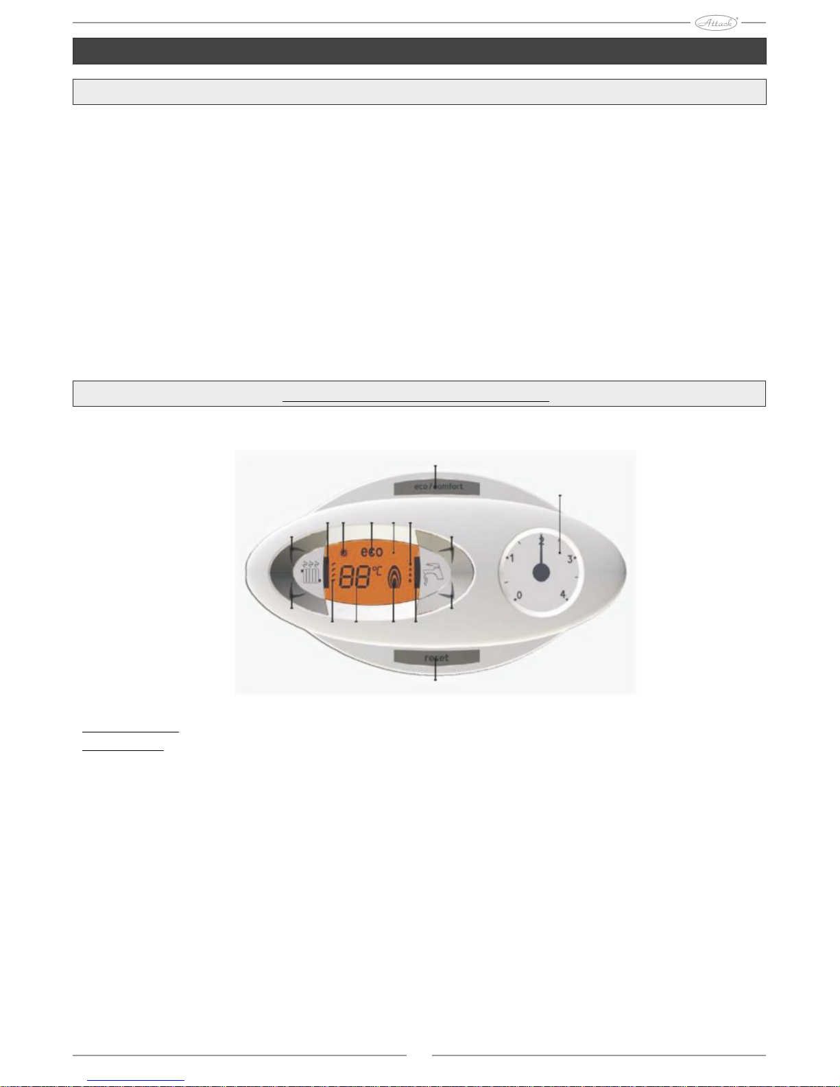
Control panel of boilers KT Plus, KT small Plus, KST Plus
Pic.1
Control panel
Description
1 = Button to decrease set temperature of D.H.W.
2 = Button to increase set temperature of D.H.W.
3 = Button to decrease set temperature of water in central heating system
4 = Button to increase set temperature of water in central heating system
5 = Display
6 = Button to recover original setting - regime option Summer/Winter
7 = Button to switch regime Economy/Comfort - Start/Stop of appliance
8 = Symbol of D.H.W.
9 = Indication of D.H.W. production
10 = Indication of regime Summer
11 = Multifunctional indication (flickers during protection function of exchanger)
12 = Indication of regime Eco (Economy)
13 = Indication of heating function
14 = Symbol of heating in heating appliance
15 = Indication of operating burner and actual output
( flickers during function of Flame protection)
7
16
14 10
4
12 5 9
2
3
13 11 15 8
1
6
Page 4

4
Indication during operation of KT Plus, KT small Plus, KST Plus
Heating
Requirement for heating (generated from room thermostat or Open therm regulator) is indicated by
flickering of LED diodes at radiator symbol (see page 13 - pic.1). Display (see page 11 - pic.1)
projects actual temperature at the inlet into heating appliance and during waiting time for heating, the
„d2“ text is displayed.
Domestic hot water
Requirement for D.H.W. (activated by taking of D.H.W. ) is signalized by flickering of LED diodes by
symbol of water tap (see page 8 - pic.1).
Display projects actual temperature at the D.H.W. outlet and during the waiting time for D.H.W., there
is a text „d1“.
Disconnection of water heater KT small Plus, KT Plus (economy)
Water warming - i.e. temperature keeping in the water heater can be turned off. In case that you turn
this function off, no D.H.W. will be produced.
User can turn the heater off (ECO regime) by pressing ECO/Comfort button (see page 7 - pic.1). In
the ECO regime, appropriate yellow control light is turned on (see page 12 - pic.1) To reactivate the
COMFORT regime, press the button ECO/COMFORT (poz. 7- obr.1 ) again.
Comfort of water heating KST Plus
Requirement for Comfort regime (comeback to original internal boiler temperature) is signalized by
flickering of LED diodes by symbol of water tap (see page 9-pic.1). Water in exchanger is
permanently warmed to temperature of 45°C. Display (see page 11-pic.1) shows actual temperature of
water in the boiler.
Start and stop of boilers KT Plus, KT small Plus, KST Plus
Boiler start
Connect appliance into electricity mains. The „FH“ is displayed within next 120 seconds, which
signalizes deareation cycle of the heating appliance. Also the version of the card software is displayed
within first 5 seconds. Open the gas valve installed on connection in front of the boiler. After
expiration of the FH text is boiler prepared for automatic operation after every usage of the DHW or
in case of requirement of the room thermostat.
Boiler stop
Hold button (see 7 - Pic.1 ) for 5 seconds.
The control electronics remains connected to the electricity mains after the boiler is shut down.
Operation of DHW warming and heating is turned off. To turn the boiler on again, hold the button for
5 seconds (see 7 - Pic.1). Boiler will be immediately ready for operation by every DHW usage or by
activation per the room thermostat. After interruption of the electrical or gas connection of device is
the antifreeze system inactive. During long-time interruption of operation, to avoid of damages caused
by frost, it is recommended to release all water from the boiler, DHW and water from supply system,
or to release only DHW and fill the supply system with antifreeze mixture that conforms to conditions
given in this manual.
Page 5

5
Regulation of the boilers KT Plus, KT small Plus, KST Plus
Switching to Summer/Winter
Hold the button for 2 seconds (see 6 - Pic.1).
The Summer sign appears on display (see 10 - Pic.1). Boiler will make only the DHW The antifreeze
system remains active. To cancel the Summer mode, hold the button for 2 seconds again (see 6 Pic.1).
Regulation of the heating water temperature
It is possible to set the temperature from the minimum of 20°C up to the maximum of 90°C by the
buttons of heating (see 3 and 4 - Pic.1).
Regulation of the DHW temperature
It is possible to set the temperature from the minimum of 10°C up to the maximum of 65°C by the
buttons of DHW (see 1 and 2 - Pic.1).
Setting of the environment temperature (with additional room thermostat)
Set the required temperature in premises by the room thermostat. If the room thermostat is not
connected, boiler will keep temperature in supply system at value that was set at the inlet into the
supply system.
Setting of the environment temperature ( additional OpenTherm regulator)
Set the required temperature in premises by the regulator. Boiler will treat water in OpenTherm
device adequately to the required temperature of environment. Farther in this manual you will find
instructions for operation with remote control.
Page 6

6
Control panel of the KZT Plus boilers
Pic.2
Control panel
Description
1 = Button to decrease adjusted DHW
2 = Button to increase adjusted DHW
3 = Button to decrease adjusted temperature of water in the central heating system
4 = Button to increase adjusted temperature of water in the central heating system
5 = Display
6 = Button for switching to Summer/Winter
7 = Button for switching to Economy/Comfort
8 = Button of reset / fill-in of device
9 = On / Off button of device
10 = Button of the „Controlled temperature“ menu
11 = Indication of achieving the required DHW temperature
12 = Sign of DHW
13 = Indication of DHW production
14 = Setting/ temperature at the DHW outlet (flickers during the „Heat exchanger protection“ operation )
15 = Indication of Eco (Economy) mode or Comfort mode
16 = Temperature of the external sensor (with additional external probe)
17 = Appears, when the external probe or the remote control is connected (optional)
18 = Temperature of environment (per additional remote control)
19 = Indication of burner operation and actual output (flickers during function „Flame protection“)
20 = Indication of operation against frost
21 = Indication of pressure in the heating device
22 = Error indication
23 = Setting / temperature at the heating device inlet (flickers during operation „Exchanger protection“)
24 = Sign of heating
25 = Indication of heating operation
26 = Indication of achieving temperature at the heating device inlet
27 = Indication of the Summer mode
Page 7

7
Start and stop of the KZT Plus
Boiler without electrical connection
Boiler is not connected to the electricity mains
When the electrical or gas connection is interrupted, the antifreeze system does not work. During
long-time interruption of operation, to avoid of damages caused by frost, it is recommended to release
all water from the boiler, DHW and water from supply system, or to release only DHW and fill the
supply system with antifreeze mixture.
Boiler start
Connect boiler to electricity mains.
The „FH“ letters will be displayed within the following 120 seconds, which means, that the air is
being released form the heating device. During the first 5 seconds is displayed also the card software
version. Open the gas valve installed on the connection with boiler.
The „FH“ text expires, the boiler is prepared for automatic operation everytime by DHW consumption
or by requirement from the room thermostat.
Boiler stop
Hold the button for 1 second (see 9 - Pic.2). When the boiler is shut down, the control electronics
remains connected to electricity. Operation of water warming and heating is turned off. The antifreeze
system remains active. To start the boiler again, hold the button for 1 second again (see 9 - Pic.2).
Boiler will be immediately ready for operation by every DHW consumption or by activation through
the room thermostat.
Indication during heating operation of the KZT Plus
Requirement for heating (activated by room thermostat or remote control) is indicated by flickering of
the warm air over space heater sign (see 24 and 25 - Pic.2).
Display (See 23 - Pic.2) shows actual temperature at the heating device inlet and the „d2“ text during
the period of waiting for heating.
Grades of heating (see 26 - Pic.2) light on sequentially, according to achieving of the value set by
thermal probe.
Domestic hot water
Requirement for water heating in the boiler is indicated by flickering of the warm water sign - marked
as water tap (see 12 and 13 - Pic.2). Display (see 14 - Pic.2) shows actual temperature at the DHW
outlet and the „d1“ during waiting for DHW. Grades of the DHW (see 11 - Pic.2) light on
sequentially, according to achieving of the temperature set by the heating device sensor.
Shutdown of the water heater (economy)
Water heating, i.e. keeping water temperature in the storage tank can be shut down. When this
function is turned off, no DHW is produced. When the DHW warming is turned on (original setting),
text „COMFORT“ is diplayed (see15-Pic.2). When it is turned off, text ECO is displayed (“See7Pic.2"). For activation of the COMFORT mode, press the button again (See 7 -Pic.2).
Page 8

8
Regulation of the KZT Plus boiler
Switching Summer/Winter
Hold the button for 1 second (see 6 - Pic.2).
The Summer sign appears on display (see 10 - Pic.1). Boiler will make only DHW. The antifreeze
system remains active. To cancel the Summer mode, hold the button for 1 second again (see 6 - Pic.2).
Regulation of the heating water temperature
It is possible to set the temperature from the minimum of 20°C up to the maximum of 90°C by the
buttons of heating (see 3 and 4 - Pic.2).
Regulation of the DHW temperature
It is possible to set the temperature from the minimum of 10°C up to the maximum of 65°C by the
buttons of DHW (see 1 and 2 - Pic.2).
Setting of the environment temperature (with additional room thermostat)
Set the required temperature in premises by the room thermostat. If the room thermostat is not
connected, boiler will keep temperature in supply system at value that was set at the inlet into the
supply system.
Environment temperature setting ( additional time remote control)
Set the required temperature in premises by the . Boiler will treat water in device time remote control
adequately to the required temperature of environment. Farther in this manual you will find instructions
for operation with time remote control.
Equithermic regulation of the KZT Plus, KST Plus, KT Plus, KT small Plus boilers
After installation of external probe (additional), the external temperature measured by the external
probe is displayed on the screen of the control panel (See 5 - Pics.1 and 2).
Boiler regulation system works with the „Controlled temperature“. In this mode is temperature of the
heating device regulated according to the external climatic conditions to ensure higher comfort and
energy savings during the whole year. Moreover, after increasing of the external temperature is the
temperature at the boiler outlet decreased according to the concrete „ compensation curve“. By
regulation of the equithermic regulation of temperature, the temperature set by the buttons of heating
(See 3 and 4 - Pics.1 and 2) represents maximum temperature at the inlet into the heating device.
It is recommended to set maximum temperature to enable system operation within the full interval.
Boiler must be set by specialist during the installation. Necessary adjustment for higher comfort can be
done by user.
Compensation curve and shift of curves of the condensing boilers Plus
Press button once to display actual compensation curve (See 6 - Pic.1 KST, KT and See 10 - Pic2 KZT).
It is possible to change it per DHW buttons (See 1 and 2 - Pic.1 and 2). Adjust the required curve from 1
to 10, adequately to the characteristics. By adjusting curve to 0 is the regulation of the controlled
temperature cancelled.
Compensation curve of the Plus condensing boilers
Access to the paralel curves shifting is enabled through heating buttons (See 3 and 4 - Pics. 1 and 2).
Flickering text (OF) is displayed. It is possible to change it through DHW buttons. (See 1 and 2 - Pics. 1
and 2).
Parallel shift of the curves of the condensing boilers Plus
Repeated pressing of the button (See 6 - Pic.1 KST, KT ) and (See 10- Pic.2 KZT ) enables to exit
mode of the parallel curve regulation. If the environment temperature is lower than required
temperature, it recommended to set more abrupt curve and vice-versa. Decrease or increase for 1 unit
and check the result in the room.
Page 9
9
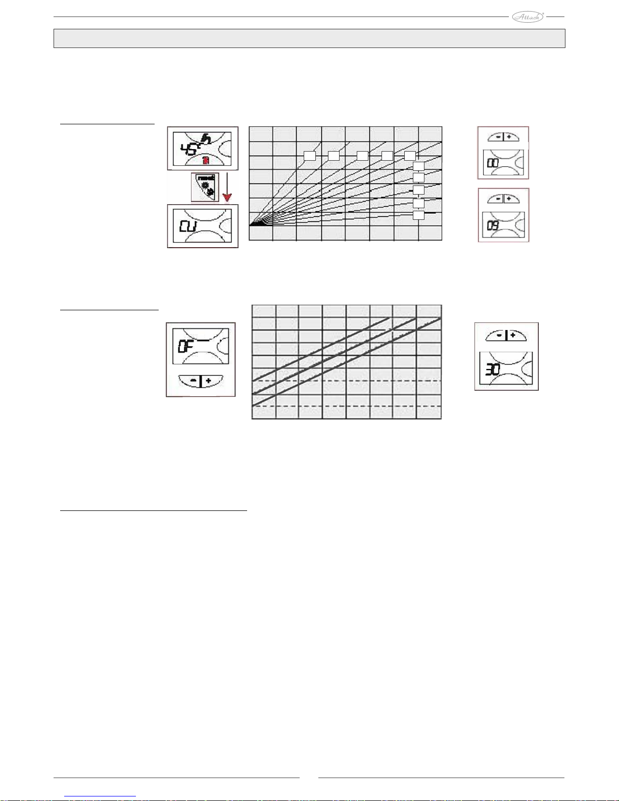
Compensation curve and curve shifting
By holding the ,,reset" button (See6 - Pic.1 KST, KT) or the ,,mode" button(See 10 - Pic.2 KZT ) for 5
seconds opens the menu of the „Controlled temperature“, the flickering „CU“ is dipslayed. Adjust the
required curve by the DHW buttons (marked as 1 and 2, pics. 1 and 2) from 1 to 10, adequately to the
characteristics. Regulation of the controlled temperature is cancelled by adjusting curve to 0.
Compensation curve
Option of the parallel curve shift, the flickering „Of“is displayed by pressing the heating buttons (See 3
and 4 - Pics.1 and 2). Set the parallel curve shift adequately to the characteristic by the DHW buttons
(See 1 and 2 - Pics. 1 and 2).
Compensation curves
Parallel curve shift
Repeated pressing of the button „Reset“ (See 6 - Pic.1 KST, KT ) and „Mode“(See 10- Pic.2 KZT ) for
5 seconds enables to exit mode of the parallel curve regulation. If the environment temperature is lower
than required temperature, it recommended to set more abrupt curve and vice-versa. Decrease or increase
for 1 unit and check the result in the room.
Regulation with time remote control
If the time remote control (additional equipment) is connected to the boiler, the above mentioned
operations are controlled per boiler display and the „FH“ text appears.
Regulation of the heating temperature
Regulation can be performed via menu of the time remote control, as well as via the boiler´s control
panel.
Regulation of the DHW temperature (with external DHW tank installed)
Regulation can be performed via menu of the time remote control, as well as via the boiler´s control
panel.
Switching Summer/Winter
The Summer mode has priority over the eventual requirement for heating from the remote control.
Selection Eco/Comfort
If the DHW warming is turned off by the remote control, boiler is switched into the Economy mode.
Therefore is the button (See 7 - Pics.1 and 2) on the boiler control panel out of order. If the DHW
warming is turned on by the remote control, the boiler is switched to the Comfort mode. Therefore it is
possible to set one of the two modes through the button (See 7 - Pics. 1 and 2).
Controlled temperature ( OPENTHERM )
The OPENTHERM communication is built into the electronic control board of the boiler. All the boiler
functions are controlled through programmable Opentherm regulator (Ordering code: OT36A).
Programmable regulator and the room thermostat are not included to the boiler accessories.
10 9 8 7 6
5
4
3
2
1
100
90
80
70
60
50
40
30
20
-20-15-10-505101520
100
90
80
70
60
50
40
30
20
-20-15-10-505101520
Page 10

10
Regulation of the hydraulic pressure of the supply device
Pressure indicated on the water-gauge, when the heating system is filled being cold, has to be 1,0 bar.
If pressure of device decreases to minumum values, boiler display shows error F 37. Increase pressure
in device to value higher than 1,0 bar by using the filling tap (See 1). Manometer indicating pressure
without electrical connection is placed in the bottom part of the boiler.When the hydraulic pressure is
recovered, boiler activates 120 seconds long ventilation cycle displayed as „FH“. Afterwards it is
always necessary to close the filling tap (See 1).
Connection to the DHW tank of the KT Plus, KT small Plus boilers
Control electronics of the boiler serves to control the external DHW tank. Make hydraulic
connections following the scheme. Make electrical connections following the instructions in the
electrical scheme (Page 13). It is always necessary to instal thermal probe for the tank. Boiler control
system detects presence of the thermal probe and automatically configures itself, activates display and
appropriate control of DHW warming.
Scheme of connection to external tank:
8 DHW outlet
9 DHW inlet
10 Inlet into the heating system (CH flow connection)
11 Return flow from the heating system (CH return
connection)
209 Inlet into the exchanger of DHW warming
210 Return flow from the exchanger of DHW warming
Page 11

11
2. Installation
General instructions
BOILER HAS TO BE INSTALLED EXCLUSIVELY BY SPECIALIZED AND TRAINED WORKERS AND ALL THE
INSTRUCTIONS GIVEN IN THIS TECHNICAL MANUAL HAVE TO BE KEPT, AS WELL AS ALL THE VALID
PRESCRIPTIONS, ALL REGULATIONS FROM THE EN NORMS, ALL STN NORMS, ALL SAFETY
PRESCRIPTIONS AND ALL WARNING SIGNS.
Place of the installation
Sphere of combustion of device is totally hermetic to the surrounding environment, and thereby it is possible to install
device in any kind of room. It is necessary to have sufficient ventilation in the room, where the boiler is going to be installed
to avoid from danger of the gas release (even if small). This safety norm is given by the Ordinance EHS Nr.90/936 for all the
gas using devices and also for devices with so called hermetic chamber. The boiler has to be installed in the dustless room,
where are no flammable materials or corrosive fumes.Room must be dry and the inside tempreture must not decrease under
0°C. Boiler has to be hung on the wall and therefore it is equipped with the console. Boiler has to be clamped in the way
ensuring its stable and efficient position. It is necessary to leave sufficient space for maintenance, in case that the boiler is
placed in the corner or if there is a furniture around. By installation , keep safe distance of the boiler surface from flammable
materials in dependence on combustibility grade:
- from materials of the combustibility grade B, C1, C2 100mm
- from materilas of the combustibility grade C3 200mm
- from materials of the combustibility grade not tested under STN 73 0853 200mm
Examples of the building materials sorting by combustible grade:
- combustible grade A - non-combustible (brick, adapting pieces, ceramic tiles, parget, mortar )
- combustible grade B -very hard combustible (heraklith, lignos, boards from basalt felt)
- combustible grade C1 - hard combustible (beech, oak, plywood, werzalit, hard paper )
- combustible grade C2 - medium combustible (pine wood, spruce chipboard, solodur)
- combustible grade C3 - easy combustible (wood-fibre-boards, polyurethane, PVC, molitane, polystyrene)
Solid materials of the combustible grade A can be used as non-combustible and isolation matters. Items made from
combustible materials must not be placed on the boiler and in the distance of 500mm from boiler.
Hydraulical connections
The ATTACK boilers are intended for heating systems with forced heating water circulation. Intensity of the water flow can
be set by switch on the pump. Before is the heating system filled with water, it is necessary to clean the system properly. It is
necessary to flush heating bodies and distribution pipes several times.To flush and clean the system properly it is
recommended to use cleansing articles. Filter must be mounted at the inlet into the heating system. It is recommended to use
copper filter with side cleaning and it has to be cleaned in regular intervals, depending on system clogging. Due to the
maintenance and servicing it is recommended to mount closing valves at the inlet and outlet of central heating and D.H.W.
Filter and valves are not delivered as accessories of the boiler. Heating system has to be also equipped with inlet valve
(installation with ATTACK KT boiler) with reverse flap, connected to water supply system to fill and pressure the heating
system. Boilers ATTACK KST and KZT Plus are equippped with filling valve with reverse flap.
Warranty is not valid for cases of clogging or stucking of exchanger or pump caused by dirts from the system!
Water callosity in the heating system cannot excess 3 mmval/l . In case of exchanger damage caused by boiler operation
with water of callosity higher than 3 mmval/l is warranty for exchanger also not valid. Expanse vessel of 7 or 8l installed in
the boiler enables connection to the closed heating system. If it is neccessary due to the size of the heating system, it is
possible to install additional expanse vessel. There should be difference of 15-20°C between outlet and inlet boiler heating
water. In case of reconstruction of the heating system or new system, it is recommended to use low-voluminous heating
appliances and distribution pipes in as small dimmensions as possible for quick system temperature reaction and
considerable flexibility of the system.
Process of filling with water: boiler has to be disconnected from electricity mains. Open deareation valves on boiler and
heating system. System has to be pressurized for at least 1 bar and deareated again. If the pressure decreases, it is neccesary
to pressurize it again.
Heating system must conform to valid norms and prescriptions:
STN 06 0310 - projection and installation of the central heating system,
STN 06 0830 - Assurance of appliance for central heating system
STN 06 0830 - Expanse vessel size
STN 07 7401 - Water in heating system
If the expanse vessel volume exceeds 7 or 8 litres it is necessary to add next expanse vessel with volume adequate to the
difference. To use maximum condensation effect it is necessary to dimensionize heating system to gradient 50/30°C. Fall
from the safety 3-bar valve has to be connected to the waste pipe. Heating system has to be equipped with suitable filter. For
maximum output of the heat exchanger, its correct function and long lifetime it is necessary to ensure minimum
overpressure of the heating system of 0,8bar. Built-in expanse vessel enables boiler connection to closed heating system.
Boiler has to be placed to ensure necessary operation conditions, adequately to design of the combustion air inlet and flue
gas exhaust.
V =V . v . 1,3
C
V - volume of expanse vessel
C
V - volume of water in heating system
v - appropriate volume increase by warming to t
m
t =80°C is v =0,029
m
Page 12

12
Antifrost system, frost-free liquids, additional mixtures or inhibitors
Boiler is equipped with antifrost system that activates boiler for heating, when the temperature of water at
the inlet into the heating system decreases under 6°C. Mechanism is not active, if appliance is
disconnected from electricity or gas. If it is necessary, it is possible to use frost-free liquids, additional
mixtures or inhibitors, but exclusively in case, that producer of the liquids or additional mixtures
guarantees, that his products are suitable for use and do not cause damage of the boiler exchanger or other
boiler parts and heating system. It is forbidden to use routine frost-free substances, additional mixtures or
inhibitors which are not exclusively intended for use in appliances producing heat and which are not
suitable for materials of boiler and distribution system.
Gas connection
Before boiler connecting, the gas connection has to be tested and revised. After boiler connection, all the
gas connections have to be tested for tightness, including pipes and armatures in boiler. Gas distribution
pipes in hte building must be done in conformity with valid norms STN EN 1775. Dismantable
connections of the gas pipes and D.H.W. pipes must not be strained by any other additional powers.
Connection to electricity mains
Boiler is intended for connection to electrical socket of 230V/50Hz placed near boiler by movable inlet
cable. Connection to electricity has to be in conformity with norm STN 33 2000-4-46, where the socket
has to be equipped with middle safety bar connected to the PE conductor.It is not allowed to use different
distributors and extension cords. Electrical voltage has to be 230V/50Hz. Plug installation, room
thermostat connection and service of electrical parts must be performed by person with special
electrotechnical qualification under the ordinance 50/1978 Zb.
Boiler is equipped with inlet electrical cable without plug. Connection to mains must be done tightly and
they must be equipped with bipolar switch with minimum contact distance of 3mm, with integrated fuse of
3A max between boiler and mais. By electrical connections it is necessary to keep polarity (PHASE:
brown conductor / ZERO: blue conductor / PROTECTION: yellow-green conductor).
Boiler is equipped with inlet electrical cable without plug. Connection to mains must be done stationary,
accessorized with bipole switch, with minimum 3mm distance of contacts, max 3A fuse engaged between
boiler and mains. It is important to keep polarity by electrical connections (PHASE:brown conductor /
ZERO: blue conductor / PROTECTION:yellow-green conductor). By installation or exchange of
electrical cable it is necessary to let grounding wire longer for 2cm than other wires. Inlet electrical cable
of device must not be exchanged by user. In case of cable damage, turn device off and call qualified
workers of authorized service. For the case of exchange of electrical inlet cable, use only the “HAR H05
VV-F” 3x0,75 mm2 cable with maximum external diameter of 8mm.
Room htermostat a Opentherm (boiler accessory)
ATTENTION: RO OM THER MOS TAT MUST H AVE CLEAN C ONTACTS . BY 230V
CONNECTION 230 V TO THERMOSTAT TERMINAL IS ELECTRONICS IRREVERSIBLY
DAMAGED.
It is necessary to connect room thermostat by copper conductor of 1-1,5mm2 diameter. For the
Opentherm´s contacts it is possible to use copper conductor with diameter of 1-1,5 mm2.
Conductors of external temperature sensor must not be lead parallely with conductors of the room
thermostat and mains connection.
External sensor (boiler accessory)
Connect sensor to appropriate terminals.Use casual 2-wire cable. It is necessary to connect room temperature sensor by
copper conductor of diameter.Maximum ohm resistance of conduction is 0,75 mm2 10kΩ, complete length is 30cm.
External probe should be rather installed on northern, north-western side or on side, where the living room is generally
placed. Probe must never be exposed to morning sun. Generally, it must not be exposed to direct sun radiance. If it is
necessary, protect it by cover. Probe must not be installed near windows, door, ventilation openings, chimneys, nor heat
sources, which could influence measured values.
Page 13

13
Wrong placing of external probe
Access to electrical terminal of the KZT Plus boiler
To access to boiler terminal, it is necessary to remove rear cover and then to make necessary electrical
connections, as it is given on scheme on the picture.
Access to electrical terminal of the KST Plus, KT Plus, KT small Plus boilers
To access to boiler terminal, it is necessary to remove rear cover and then to make necessary electrical
connections, as it is given on scheme on the picture. After connection of external tank through
temperature sensor it is necessary disconnect both resistances on terminal. If tank is connected through
tank thermostat, it is only necessary to disconnect resistance1,8k .
Page 14
14
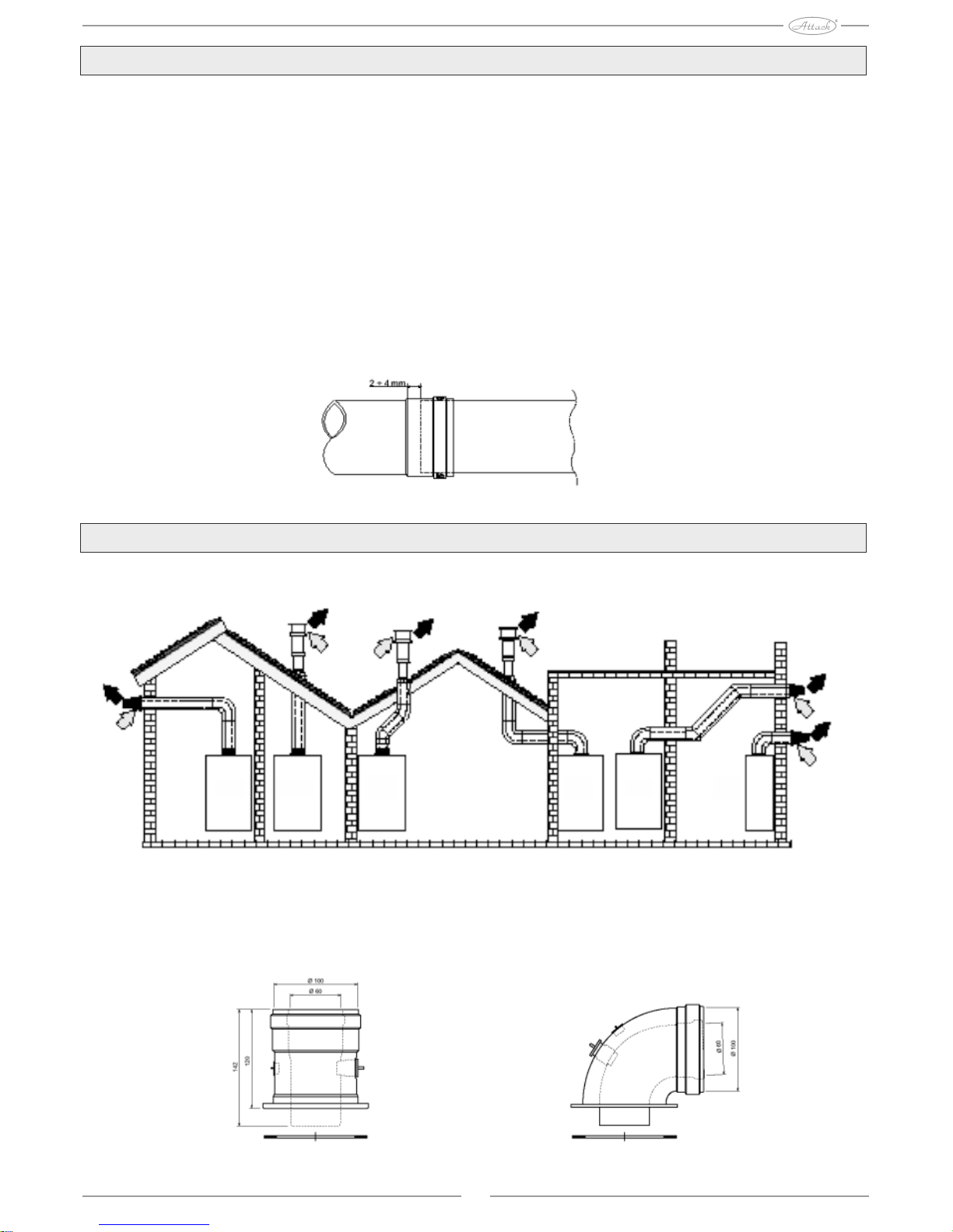
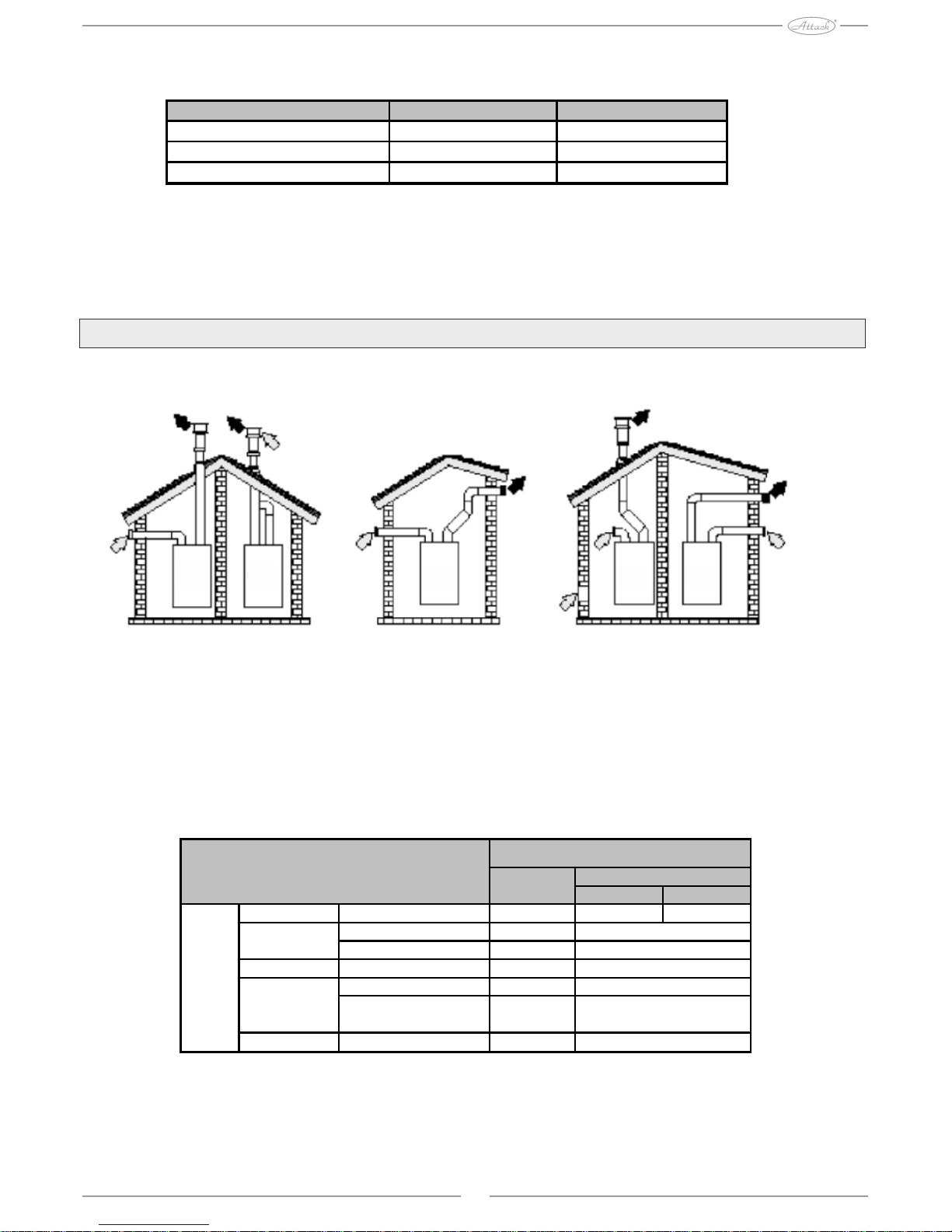
Flue gas exhausts
This appliance is a C type, with hermetic chamber and forced exhaust, air inlet and flue gas outlet have
to be connected to one of the systems of outlet / suction mentioned further. Appliance is homologized for
operation with all chimneys Cxy, that are listed on label with technical data (some configurations are
given only as example in this chapter). Despite of that there is a possibility, that some configurations will
be literally limiting or they will not conform to prescriptions, norms or national regulations. Check and
strictly keep all instructions before installation. Except of that, keep instructions concerning placement
of endings on wall ot roof and minimum distances from windows, walls, ventilation openings, etc.
This appliance of C type has to be installed by usage of suction pipes and exhaust outlets supplied by
producer, in conformity with UNI-CIG 7129/92. In case, that these are not used, any warranty and
producer´s reliability expires. By installation of flue gas exhausts longer than 1m it is necessary to
consider natural material extension of materials by operation. To prevent deformations, let dilatation
space of 2 ÷ 4 mm approximately, per 1m of length.
Extension
Connection by coaxial pipes
Examples of connection by coaxial pipes
By coaxial connection, mount one of the following accessory pieces to appliance. It is necessary to keep
slight downgrade of horizontal parts of flue gas exhaust to boiler, in order to prevent eventual condensed
water leaks out and drops.
Accessories by coaxial connection
C
13
C
33
C
33
C
33
C
13
C
13
Page 15
15
C
53
C
33
C
53
C
23
C
13
Air suction
Vertically Horizontally
Pipe 1m O/M 1 1,6 2
45° O/M 1,2
90° O/M 1,5
Distribution with control opening 0,3
air to wall 2
Chimney Air/flue gas 80/80
2
0,3
Losses in m/eq
Flue gas outlet
1,8
Elbow
Ø 80
Endpiece
12
5flue gas to wall
Maximum length of coaxial outlets
Before installing it is necessary to check, if the maximum permitted length has not been exceeded.
Every coaxial arc means length reduction, as it is given in the table. For example, connection 60/100
with elbow of 90° + 1m of horizontal outlet means equivalent length of 2m. Before installation it is
necessary to check, if the max.permitted length was not exceeded (concern, that every coaxial bow
causes length reduction as it is given in the table).
Connection by separate tubes
Examples of connection with separate tubes
Before installing, check by simple calculation, if total length does not exceed maximum length:
1. Make final calculation of scheme of double chimneys, including accessories and endings.
2. Check table 4 - losses in meq (equivalent meters) for every item, in dependence from its position in
installation.
3. Check, if total amount of losses is lower or equal to the maximum permitted length given in the table.
Maximum length of separate tubes
Separate tubes
Maximum permitted length 75 meq
Coaxial 60/100 Coaxial 80/125
Max. permitted length
5m 10m
Factor of elbow reduction
90° 1m 0,5m
Factor of elbow reduction 45° 0,5m 0,25m
Page 16

Accessories
Connection to mutual chimneys
Examples of connection to chimneys
If you decide to connect boilers ATTACK Plus to mutual or separate chimney with natural exhaust,
mutual or separate chimney has to be projected exclusively by specialized worker in conformity with
valid norms for appliances with hermetic chamber, equipped with fan.
Moreover, it is necessary to keep following characteristics of mutual / separate chimneys:
- dimensionised by calculation method given in valid norms
- proof against flue gas, resistant against smoke and heat, proof against condensed water
- circular or quadrilateral diameter, vertical , without reductions
- with pipe, that takes hot flue gas out, they are adequately remote or isolated from flammable materials
- with connection to single appliance on 1 floor
- with connection to same appliances (or different, but all appliances only with forced flue gas outlet or
only with natural flue gas exhaust)
- without mechanical means for suction in main pipes
- with underpressure in all their length, in conditions of stationary operation.
- in their platform they have collection tank for solid material or eventual condense water, equipped with
metal door with airtight closing.
Connection to condense water outlet
Boiler is equipped with internal syphon for condence water outlet. By first installation, mount inspection
connection (A). Mount flexible pipe of condense outlet (B) to outlet of boiler´s syphone by extending it
for 3cm approximately and fit it by fixing bolt. Fill syphone for 0,5l of water (2) approximately and
connect flexible pipe to outlet device (3).
Outlet of condense water
16
C
83
C
43
C
43
Page 17

3. Operation and maintenance
All operations for regulation and adjustment according to type of gas must be done by qualified and
trained workers (professional technicians, that respect valid technical norms) - the authorized
servicemen. ATTACK takes no responsibility for damages on properties, nor injuries of persons that are
caused by incorrect manipulation with appliance by unqualified or unauthorized persons.
Regulation
Adjustment according to type of gas
Appliance works on natural gas (G20) or propane (G31). Adjustment of appliance for concrete gas type is
performed by producer, as it is given on the serial label. In case that it is necessary to use appliance with
another type of gas, than it is intended, it is necessary to ensure appropriate set for transformation. Then it
is necessary to make the following steps:
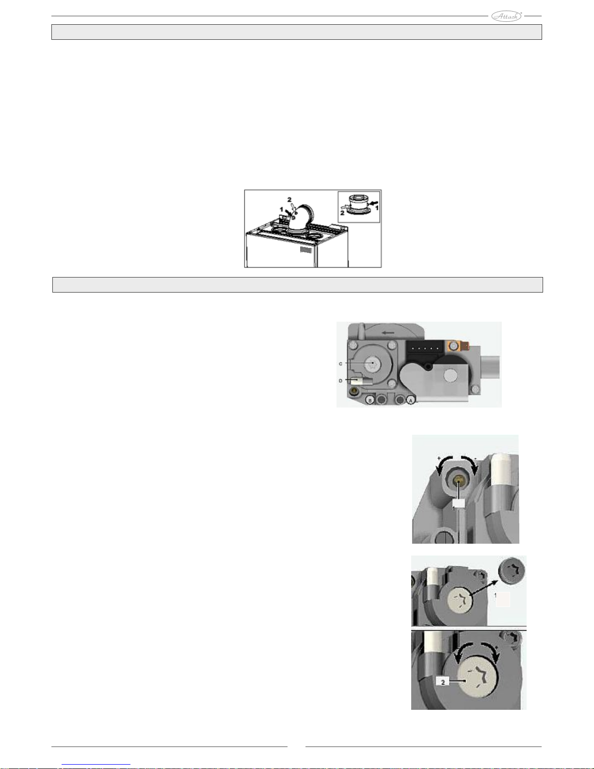
1. Remove covering
2. Open hermetic chamber
3.Hang down fixing clip C and pick gas pipe A out of the fan unit - Venturi.
4. Exchange nozzle B laid inside the gas pipe for nozzle from boiler transformation set.
5. Fix the gas pipe A back by clip and check, if the sealing is tight
6. Mount hermetic chamber and covering again.
7.Modify parameter related to the gas type:
switch boiler into the stand-by mode, hold DHW buttons pressed (pos. 1 and 2 - pic. 1 and 2) for 10
seconds: flickering „PI01“ is displayed
by pressing DHW button (pos. 1 - pic.1 and 2), set parameter 00 (by operation for natural gas) or 01 (by
operation for propane). Hold DHW button pressed (poz.1 - pic. 1 and 2) for 10 seconds. Boiler gets back
to stand-by mode.
8. Check inlet operation pressureat the gas valve inlet.
9. Use combustion analyser, connected to the exhaust outlet from boiler to check, if the CO2 content in
flue gas, by max. and min. boiler output, is adequate to the supposed content given in the table with
technical data for appropriate gas type.
Gas nozzle exchange
17
Page 18
Analysis of combustion
Combustion is analysed in air (2) and flue gas (1) exemption areas as it is given on the picture. For
measuring it is necessary to:
1.Open exemption areas of air and flue gas
2.Put probes in
3.Press buttons "+" and "-" by heating sign for 5 seconds to activate the TEST mode
4.Wait 10 minutes until boiler gets into stable operation
5.Measure
Value of CO2 has to be in interval of 8,7 - 9% by natural gas (G20). By propane (G31) it is 9,5-10%.
In case, that analysis is done, while boiler is not in stable operation, errors in measuring may occur.
Combustion analysis
Setting of CO2 value by combustion
Setting and check of the CO2 on gas valve can be only by qualified service technician!
Description of gas valve:
A - Inlet pressure
B - Outlet pressure
C - Regulation screw - min. output setting
D - Regulation screw - max. output setting
By max.output is CO2 set by regulation screw D, by max.output is CO2 set by regulation screw C
Co2 test by max. output:
1- Put device for combustion analysis into flue gas outlet pipe.
2- Start boiler and test mode by pressing "+" and "-" buttons by heating
sign for 5 seconds.
3- Use "+" button to set heating to max output (100%)
4- Check, eventually set CO2 values by screw (1) for the range of
8,7 - 9,2 % for natural gas (G20) and 10 - 10,5 % for propane (G31)
5- Exit test mode after correct setting.
CO2 test by min output:
1- Put device for combustion analysis into flue gas outlet pipe.
2- Start boiler and test mode by pressing "+" and "-" buttons by heating
sign for 5 seconds.
3- Use "-" button to set heating to min. output (0%)
4- Check, eventually set CO2 values by screw (1) for the range of
8,7 - 9,2 % for natural gas (G20) and 10 - 10,5 % for propane (G31)
5- Set back to 100% and exit test mode after correct setting.
18
Page 19

Activation of the TEST mode
Press heating buttons together for 5 seconds to activate the TEST mode (see 3 and 4 - pics.1 and 2). Boiler
is started by maximum output of the set heating and actual value, as it is given in the text below.
Signs of heating and DHW flicker on display and temperature of heating. Values of actual heating output
and actual value of flame flow (uA x 10) are also displayed.
To exit TEST mode, repeat same process as by activation. TEST mode is everytime automatically
stopped after 15 minutes.
Regulation of heating output
To make regulation of heating output, set boiler into the TEST mode. Press buttons of heating (see 3 and
4, pics. 1 and 2) to increase or to decrease output (Minimum = 00 - Maximum = 100). If the RESET button
is pressed for 5 seconds, maximum output stays at the level that was actually set.Exit TEST mode.
Operation start-up
Before start and after all installation actions that required disconnection from distribution network or
works on safety mechanisms or boiler parts, it is necessary to check the following:
Before boiler start
- open eventual control valves installed between boiler and distribution network.
- check tightness of connections, if there is no gas leakage; be carefull and use soap water solution
- check pressure of expanse vessel overfill
- fill hydraulic devices and ensure absolute deareation of boiler and heating system - open deareation
valve on boiler, eventually deareation valves of distribution system
- check pressure in heating system, cca 1bar. in cold state
- fill outlet syphone and check correct connection to outlet device for condense water
- check, if there is no water leakage in the heating system, DHW circuit, connections or in the boiler
- check accuracy of connection of electrical device and functionality of grounding
- check if pressure value and gas overflow for heating are adequate to requirements
- check, if there are no flammable liquids or other materials in near surrounding of boiler
Checking during operation
- Turn device on
- Check tightness of gas circuit and heating system
- Check tightness of chimney and air-flue gas exhausts during boiler operation
- Check correct tightness and functionality of syphone and device of outlet of condensed water
- Check correct water circulation between boiler and heating system
- Check correct modulation of gas valve by heating and also by DHW preparation
- Check correct boiler start by several tests of start and stop by room thermostat or by remote time
controller
Use combustion analyser, connected to the flue gas outlet from the boiler to check, if the CO2 content in
flue gas - by max. and min. boiler output - is adequate to the supposed content given in the table with
technical data for appropriate gas sort, eventually adjust it , as it is given in the instructions in chapter
about CO2 adjustment on page 18.
-Check, if fuel consumtion, displayed on counter, is appropriate to consumption given in the table with
technical data.
- Check correct parameter programming and make eventual adjustments according to your needs
(compensation curve, output, temperatures, etc.)
19
Page 20
Maintenance
Regular check
To keep long-time functionality and effectivity of device, qualified worker must regularly perfom the
following tests:
- Control and safety elements (gas valve, flow sensor, thermostats, etc.) must work correctly
- Circuit of flue gas exhaust must be perfectly tight
- Closed chamber has to be tight
- Pipes and ending air-flue gas must have no barriers, nor leakage
- System for condense water outlet must be functional, without barriers and it cannot leak
- Burner and exchanger must be clean and without sediments. By eventuall cleaning, do not use
chemical means, nor steel brushes.
- Electrode must be placed correctly, with no sediments
- Gas and water supply connections must be ensured against leakage
- Pressure of water in distribution device in cold state must be approximately 1 bar. If pressure is
different, adjust this value.
- Circulation pump must not be blocked
- Expanse vessel must be filled
- Flow and gas pressure must correspond to data given in appropriate tables
Cover, control panel and external parts of boiler can be cleaned by soft wet cloth, eventually soak in water
with cleaner. Do not use abrasive cleaners nor dissolvents.
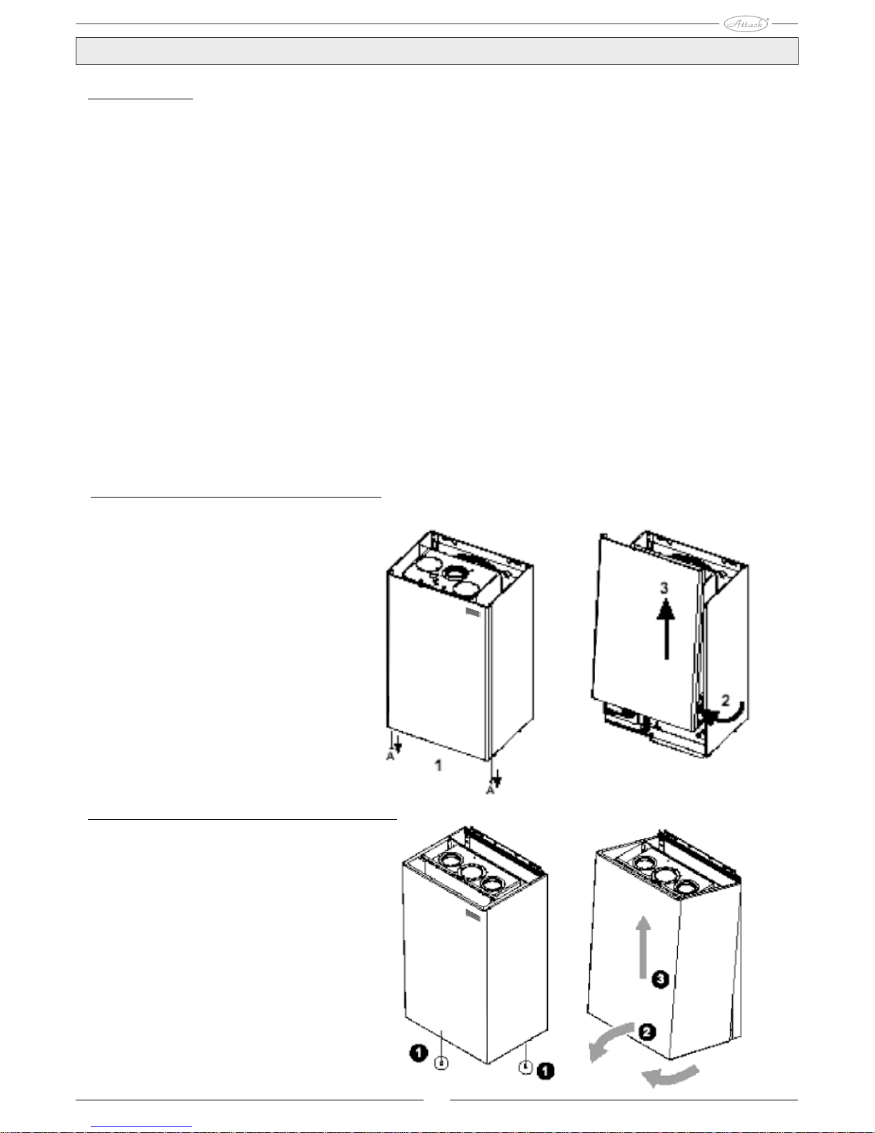
How to open cover of the KZT Plus boiler
To open cover of boiler:
1. Dismantle screws A (1)
2. Pull cover to open (2)
3. Lift up and remove cover (3)
How to open cover of the KST Plus, KT Plus, KT small Plus boilers
To open cover of boiler:
1. Dismantle screws (1)
2. Pull cover to open (2)
3. Lift up and remove cover (3)
20
Page 21

Table of error messages
Diagnostics
Boiler is equipped with modern system for autodiagnostics. In case of boiler error, display flickers
together with the sign of error and number indicating error code.
There are errors, that cause permanent blockage (marked by „A“ letter): to get boiler back to normal
operation, press RESET button for 1 second or use RESET on remote time controller (additional), if
it is installed; if boiler does not come to operation, it is necessary to remove the fault. Errors (marked
by „F“ letter) cause often blockages, that are automatically removed, immediately after the value gets
back into the interval of normal boiler operation.
21
Code Error Possible cause Solution
Check, if gas inlet into boiler is balanced and if pipes are deareated
Error of ignition and ionisation electrode
Check cable connection of electrodes, their correct placing and
if there are no sediments on them
Damaged gas valve Check and change gas valve
Insufficient gas pressure in network Check gas pressure in distribution network
Blocked syphon Check and clean syphon, if necessary
Signal of flame presence
by extinguished burner
Error of electrode Check cable connection of ionisation electrode
Damaged sensor of heating Check correct placing and operation of central heating sensor
Water in device does not circulate Check circuiting pump
Areated heating system Deareate heating system
Intervention of fuse of flue
gas and smoke exhaust
Error F07, that occured 3-times
in last 24 hours
Action of ventilator fuse
protection
Error F15 that remained for 1 hour
period
Error of ionisation electrode Check position of ionisation electrode or exchange it
No flame in start-up phase Unstable pressure Check burner
(6-times within 4 min.) Error Check setting of gas valve by min. output
Flue gas outlet clogged Remove barries from piping of flue gas outlet
Syphon clogged Check and eventually clean the syphon
Damaged sensor
Sensor failure at the entry
Cabling under shortage
into distribution device 1
Aborted cables
Damaged sensor
Failure of sensor of return flow
Cabling under shortage
Aborted cables
Damaged sensor
Sensor failure at the entry
Cabling under shortage
into distribution device 2
Aborted cables
Supply voltage lower than
170V
Incorrect frequency in
electrical mains
Incorrect water pressure in Too low pressure Refill system with water
device Damaged sensor/ switch of pressure Change the RZT sensor or RT,RST pressure sensor
F39 External probe error Damaged sensor or shortage Change sensor or check connection of cables
Incorrect water pressure in Check safety valve
device Check pressure in expanse vessel
A41 Placing of sensors Sensor disconnected from pipe Check correct placing of sensor
F42 Error of heating sensor Damaged sensor Change sensor
Water in device does not circulate Check circuit pump
F43 Safety action of exchanger Areated distribution device
F47 Error of pressure sensor Aborted cables Check connection of cables
F50 Error of modulation reel Aborted cables Check connection of cables
Check connection of cables or change sensor
F14
Check connection of cables or change sensor
Problems with electricity mains Check electricity mains
F34
F11
See error F15
A05
A06
F10
Check connection of cables or change sensor
Boiler overheating
A03
A04
See error F07
No gas is supplied
Burner did not ignit
A01
Check electronicsError of control electronics
A02
Deareate heating system
F40
Too high water pressure
Problems with electricity mains Check electricity mains
F35
F37
Page 22

400330
700
4. Characteristics and technical data
Dimensions and connections of the KZT Plus
boiler
Dimensions and connections
1 = Inlet into heating system (c.h. flow connection)
2 = Outlet of supply water
3 = Gas inlet
4 = Inlet of supply water
5 = Return flow from heating system (c.h.return flow)
Dimensions and connections of the KT Plus
boiler
Dimensions and connections
1 = Inlet into heating system (c.h. flow connection)
3 = Gas inlet
5 = Return flow from heating system (c.h.return flow)
6 = Safety valve release
22
80 120 120 130
1 2 3 4 5
460
302
362
97 94,5 51 54 80 73,5
80 120 120 80
82 74 56 48 84 56
229
180
118
180
232
1 3 6 5
195
362
841
809
10,5
32
198
120
360
45
200 200
450
450
460
45
70 52 52 116 63,5 106,5
44
318
Page 23

Dimensions and connections of the KST Plus
boiler
Dimensions and connections
1 = Inlet into heating system (c.h. flow connection)
2 = Supply water outlet
3 = Gas inlet
4 = Supply water inlet
5 = Return flow from heating system (c.h.return flow)
6 = Safety valve release
Dimensions and connections of the KT small
Plus boiler
Dimensions and connections
1 = Inlet into heating system (c.h. flow connection)
3 = Gas inlet
5 = Return flow from heating system (c.h.return flow)
6 = Safety valve release
1 2 3 4 5 6
82,5 76 54 51 80,5 56
231
179
80 120 120 80
195
700
400
330
1 3 6 5
32,5 50 78,8 79,5 53,7
300
320
700
23
165
68 120 132
25,5
Page 24

Main parts of the KZT Plus boiler
5 Hermetic chamber
7 Gas inlet
8 Supply water outlet
9 Supply water inlet
10 Inlet into heating system (c.h.flow connection)
11 Return flow from heating system (c.h.return connection)
14 Safety valve
16 Ventilator
19 Combustion chamber
22 Ceramic burner
29 Collector on flue gas outlet
32 Circuit pump of heating
36 Automatic deareation valve
37 Filter on cold water inlet
40 Expanse vessel of supply water
44 Gas valve
56 Expanse vessel
74 Tap to fill distribution device
82 Ionisation electrode
95 Three-way valve
130 Pump of supply water
145 Manometer
161 Heat exchanger
186 Sensor of heating water return connection
188 Ignition electrode
191 Sensor of flue gas temperature
193 Syphon
194 Exchanger of supply water
195 Stainless steel tank for supply water 25lit.
196 Condensate collector
243 Sensor of supply water temperature
246 Pressure sensor
250 Filter on inlet into heating system
278 Double sensor (Safety + Heating)
24
Page 25

Main parts of the KST Plus boiler
5 Hermetic chamber
7 Gas inlet
8 Supply water outlet
9 Supply water inlet
10 Inlet into heating system (c.h. flow connection)
11 Return flow from heating system (c.h. return
connection)
14 Safety valve
16 Ventilator
19 Combustion chamber
22 Cearmic burner
29 Collector at flu gas outlet
32 Circuit pump of heating
36 Automatic deareation valve
37 Filter at cold water inlet
39 Regulator of supply water flow
42 Temperature sensor of supply water
44 Gas valve
56 Expanse vessel
74 Tap to fill distribution device
82 Ionisation electrode
95 Three-way valve
114 Sensor of water sensor
136 Flow sensor
161 Heat exchanger
186 Sensor of heating water return connection
188 Ignition electrode
191 Sensor of flue gas temperature
193 Syphon
194 Heat exchanger of supply water
196 Collector of condensate
201 Mixing Venturi pipe
250 Filter at inlet into heating system
278 Double sensor (Safety + Heating)
25
Page 26

5 Hermetic chamber
7 Gas inlet
10 Inlet into heating system (c.h.flow connection)
11 Return flow from heating system (c.h.return
connection)
14 Safety valve
16 Ventilator
19 Combustion chamber
22 Main burner
29 Collector at flue gas outlet
32 Circuit pump of heating
36 Automatic deareation valve
44 Gas valve
56 Expanse vessel
74 Tap to fill distribution device
82 Ionisation electrode
95 Three-way valve
114 Sensor of water pressure
161 Heat exchanger
186 Sensor of return connection of heating water
188 Ignition electrode
191 Sensor of flue gas temperature
193 Syphon
196 Collector of condensate
201 Mixing venturi pipe
209 Outlet into water tank
210 Return flow from water tank
250 Filterat inlet into heating system
278 Double sensor (Safety + Heating)
26
Main parts of KT Plus, KT small Plus boilers
Page 27

Hydraulic circuit of the KZT Plus boiler
7 Gas inlet
8 Outlet of domestic hot water
9 Inlet of domestic hot water
10 Inlet into heating system (c.h.flow connection)
11 Return flow from heating system (c.h. return
connection)
14 Safety valve
16 Ventilator
32 Circuit pump of heating
36 Automatic deareator
40 Expanse vessel of supply water
44 Gas valve
56 Expanse vessel
74 Tap to fill distribution device
95 Three-way valve
97 Magnesium anode
130 Pump of supply water
154 Pipe for condensed water outlet
161 Heat exchanger
186 Sensor of heating water return connection
191 Sensor of flue gas temperature
193 Syphon
194 Exchanger of supply water
195 Stainless tank of supply water 25lit.
196 Collector of condensate
241 Automatic by-pass
243 Sensor of supply water temperature
246 Pressure sensor
250 Filter at inlet into heating system
278 Double sensor (Safety + Heating)
27
Page 28

Hydraulic circuit of the KST Plus boiler
7 Gas inlet
8 Domestic hot water outlet
9 Domestic hot water inlet
10 Inlet into heating system (c.h.flow connection)
11 Return flow from heating system (c.h. return
connection)
14 Safety valve
16 Ventilator
32 Circuit pump of heating
36 Automatic deareator
37 Filter at cold water inlet
42 Temperature sensor of supply water
44 Gas valve
56 Expanse vessel
74 Tap to fill distribution device
95 Three-way valve
114 Water pressure sensor
136 Sensor of supply water flow
154 Outlet pipe of condensed water
161 Heat exchanger
186 Sensor of heating water return connection
193 Syphon
194 Heat exchanger of supply water
196 Condensate collector
241 Automatic by-pass
250 Filter at inlet into heating system
278 Double sensor (Safety + Heating)
28
Page 29

Hydraulic circuit of the KT Plus, KT small Plus boilers
7 Gas inlet
10 Inlet into heating system (c.h.flow connection)
11 Return flow from heating system (c.h. return
connection)
14 Safety valve
16 Ventilator
32 Circuit pump of heating
36 Automatic deareator
44 Gas valve
56 Expanse vessel
74 Tap to fill distribution device
95 Three-way valve
114 Water pressure sensor
154 Condensed water outlet
161 Heat exchanger
186 Sensor of heating water return connection
193 Syphon
196 Collector of condensate
209 Inlet into water tank
210 Return flow from water tank
241 Automatic by-pass
250 Filter at inlet into heating system
278 Double sensor (Safety + Heating)
29
Page 30

Technical data KZT Plus, KST Plus, KT Plus, KT small Plus
30
Data Unit
KZT Plus KST Plus KT Plus KTsmall Plus
Max. thermal power of central heating
kW 25,2 25,2 25,2 18
Min. thermal power of central heating kW 5,3 5,3 5,3 3
Max. thermal output of central heating (80/60°C) kW 24,6 24,6 24,6 17,7
Min. (80/60°C)thermal output of central heating kW 5,2 5,2 5,2 2,9
Max. (50/30°C)thermal output of central heating kW 26,6 26,6 26,6 19
Min. (50/30°C)thermal output of central heating kW 5,7 5,7 5,7 3,2
Max. thermal power of DHW kW 27 27
Min. thermal power of DHW kW 5,3 5,3
Max. thermal output of DHW kW 26,5 26,5
Min. thermal output of DHW kW 5,2 5,2
Pressure of gas connection G20 mbar
Max. gas flow G20 m3/h 2,86 2,86 2,86 1,9
Min. gas flow G20 m3/h 0,56 0,56 0,56 0,32
Pressure of gas connection G31 mbar
Max. gas flow G31 kg/h 2,11 2,11 2,11 1,41
Min. gas flow G31 kg/h 0,41 0,41 0,41 0,23
Max. substantive flue gas overflow
kg/h 30,3
Min. substantive flue gas overflow kg/h 5,3
Max. flue gas temperature °C 63
Min. flue gas temperature °C
Class of efficiency by directive 92/42EHS
Emissions class Nox
Max. operation pressure by heating bar
Min. operation pressure by heating bar
Max. temperature into heating °C
Water volume in boiler in central heating litre 1,5 1,5 1,5 1
Volume of expanse vessel of central heating
litre 8 8 8 7
Pressure of central heating expanse vessel overflow
bar
Max. pressure of central heating bar 9 9
Min. pressure of central heating bar 0,25 0,25
Water volume in boiler in DHW litre 25 0,3
DHW flow t 25°C l/min 15,2
DHW flow t 30°C l/min 12,7
DHW flow t 30°C l/10min 160
DHW flow t 30°C l/hod 790
Volume of DHW expanse vessel litre 2
Pressure of DHW expanse vessel overflow bar 1
Protection of electrical parts IP
Voltage of electrical mains V/Hz
Electrical input W 180 120 120 115
Electrical input by DHW production W 180 120
Weight of empty boiler kg 53 37 36 31
Sort of appliance
Value
5
C13-C23-C33-C43-C53-C63-C83-B22
230/50Hz
X5D
95
0,8
3
20
1
37
60
41,2
9,4
62
Page 31

31
Electrical scheme of the KZT Plus boiler
16 Ventilator
32 Circuit pump of heating
42 Sensor of supply water temperature
44 Gas valve
72 Room thermostat
82 Ionisation electrode
95 Three-way valve
130 Circuit pump of water tank
138 External sensor
139 Remote time controller
186 Sensor of return flow of heating water
188 Ignition electrode
191 Sensor of flue gas temperature
246 Pressure sensor
256 Signal of pump of modulation heating
278 Double sensor (Heating + Safety)
A Contact EKO/KOMFORT
OPENED = mode eco/comfort enabled by
control panel or remote controller
CLOSED = mode eco/comfort disabled;
comfort mode remains active
Electrical scheme of the KST Plus boiler
16 Ventilator
32 Circuit pump of heating
42 Sensor of supply water temperature
44 Gas valve
72 Room thermostat
82 Ionisation electrode
95 Three-way valve
114 Switch of water pressure
136 Flow sensor
138 External sensor
139 Remote time control
186 Sensor of return flow of heating water
188 Ignition electrode
191 Sensor of flue gas temperature
278 Double sensor (Heating + Safety)
A Contact ON/OFF of flow sensor
Page 32

Electrical scheme of the KT Plus, KTsmall Plus boilers
6 Ventilator
32 Circuit pump of heating
42 Sensor of supply water temperature
44 Gas valve
72 Room thermostat
82 Ionisation electrode
95 Three-way valve
114 Switch of water pressure
138 External sensor
139 Remote time controller
186 Sensor of return flow of heating water
188 Ignition electrode
191 Flue gas temperature sensor
278 Double sensor
(Heating + Safety)
Diagram of pressure losses by filling and height differences of pumps of boilers KZT
Plus, KST Plus, KT Plus, KTsmall Plus
A Losses of boiler infill
1-2-3 Speed of circuit pump
32
Page 33

33
Accessories of flue gas exhaust
Accessories of coaxial flue gas exhaust with diameter of 60/100mmÆ
Code Name
PR37 extension 1m D60/100 paint
Pr38 0,5m D60/100 paintextension
PR39 chimney 60/100 paint
PR40 elbow 90° D60/100 paint
PR41 elbow 45° D60/100 paint
PR42 elbow with flange + service opening D60/100
PR43 vertical flange + service opening D60/100
PR44 endpipe D60/100 paint
Accessories of double flue gas exhaust and air suction with diameter of 80 mmÆ
Code Name
PR45 pipe of exhaust and suction 1m D80
Pr46 1 m D80extension
Pr47 0,5 m D80extension
PR48 elbow 90 D80 O/M °
PR49 elbow 45° D80 O/M
Pr50 chimney D80
PR51 vertical distributor D60/100 - D80/80
Temperature sensors of heating, hot water heating and flue gas
Table of temperature dependence of resistivity
Temperature ( °C ) 100 90 80 70 60 50 40 30 25 15 5
Resistivity ( K Ohm ) 0,68 0,92 1,25 1,7 2,5 3,6 5,3 8 10 15,6 25,3
Sensor of central heating inlet Flue gas sensor Double sensor
Page 34

34
Page 35

Stamp, signature of service organization : ......................................................
Obligatory service examination after the 1st year of operation
Date : ........................................
Stamp, signature of service organization : ......................................................
Obligatory service examination after the 2nd year of operation
Date : ........................................
Stamp, signature of service organization : ......................................................
Obligatory service examination after the 3 rd year of operation
Date : ........................................
This page serves for confirming service examinations and is kept by a customer ! ! !
RECORD ON PUTTING THE BOILER TO OPERATION
Data on the customer (llegible)
Production number.............................. Name and surname:
Date of putting to operation................ .........................................
Service organization: Street: .............................
............................ Post code, town:.
.Stamp, signature ........................................
........................................................ Tel. No. ..........................
Page 36

ATTACK, s.r.o.
Dielenská Kružná 5020
038 61 Vrútky
Slovakia
Tel: +421 43 4003 103
Fax: +421 43 4003 116
E-mail: export@attack.sk
Web: www.attack.sk
Výrobca ATTACK, s.r.o. si vyhradzuje právo technických zmien výrobkov bez predchádzajúceho upozornenia. • ATTACK, s.r.o. producer reserves the right to change
technical parameters and dimensions of boilers without previous warning. • Der
Hersteller ATTACK, s.r.o. behält sich das Recht der technischen Veräderungen an
Produkten ohne eine vorige Warnung. • Изготовитель АТТАCK, s.r.o. оставляет
за собой право изменения технических параметров и размеров котла без
предыдующего предупреждения. • Le producteur ATTACK, s.r.o. réserve le
droit des modifications techniques sans l‘avertissement précédent. • Produc tor
ATTACK, s.r.o. reserva el derecho de cambios técnicos sin advertencia anterior.
ATTACK, s.r.o. – 12/2013
 Loading...