

Page 1

THE ACCUMULATION TANKS
ATTACK®
AK/AS, HR/HRS, TUV/TUVS, S/SS
INSTRUCTION MANUAL
W W W . A T T A C K . S K
Page 2

2
CONTENTS
1. General information . . . . . . . . . . . . . . . . . . . . . . . . . . . . . . . . . . . . . . . . . . . . . . . . . 2
2. Description of device . . . . . . . . . . . . . . . . . . . . . . . . . . . . . . . . . . . . . . . . . . . . . . . . 2
2.1. Type . . . . . . . . . . . . . . . . . . . . . . . . . . . . . . . . . . . . . . . . . . . . . . . . . . . . . . . . . . 3
2.2. Thermal insulation . . . . . . . . . . . . . . . . . . . . . . . . . . . . . . . . . . . . . . . . . . . . . . . . 3
2.3. Specification . . . . . . . . . . . . . . . . . . . . . . . . . . . . . . . . . . . . . . . . . . . . . . . . . . . . 3
3. Technical data and dimensions . . . . . . . . . . . . . . . . . . . . . . . . . . . . . . . . . . . . . . . 3 – 11
4. Operation . . . . . . . . . . . . . . . . . . . . . . . . . . . . . . . . . . . . . . . . . . . . . . . . . . . . . . 12
5. Installation . . . . . . . . . . . . . . . . . . . . . . . . . . . . . . . . . . . . . . . . . . . . . . . . . . . . . . 12
5.1. Connection to the heat source . . . . . . . . . . . . . . . . . . . . . . . . . . . . . . . . . . . . . . . . 12
5.2. Connection of the electrical heating bodies . . . . . . . . . . . . . . . . . . . . . . . . . . . . . . . 12
6. Putting into the operation . . . . . . . . . . . . . . . . . . . . . . . . . . . . . . . . . . . . . . . . . . . . 12
7. Maintenance . . . . . . . . . . . . . . . . . . . . . . . . . . . . . . . . . . . . . . . . . . . . . . . . . . . . . 13
8. Disposal . . . . . . . . . . . . . . . . . . . . . . . . . . . . . . . . . . . . . . . . . . . . . . . . . . . . . . . 13
THE ATTACK ACCUMULATION TANKS
The ATTACK, s.r.o. company is the largest manufacturer of the accumulation tanks in Slovakia
with the widest offer of these items.
1. GENERAL INFORMATION
This instruction manual is an inseparable and important part of the product. Read the instructions given in this manual carefully, as they contain important information about safety, installation, usage and maintenance. Keep this manual to be eventually used in future. This appliance is
constructed for accumulation and subsequent distribution of the heat energy from the heat sources as well as for preparation of the D.H.W.
It is forbidden to use this appliance for other purposes than given above (e.g. as a D.H.W.
tank), except of the tanks with a built-in D.H.W. tank. Producer takes no responsibility for
damages caused by unsuitable or incorrect usage.
Before starting the work on device or its maintenance, disconnect the electrical power inlet. If
there are any marks of fault on the appliance, stop the operation and call a service technician.
2. DESCRIPTION OF DEVICE
The tanks serve for accumulation and subsequent distribution of the heat energy from solid fuel boilers, heat pumps, electric boilers, etc. The accumulation tanks ATTACK AS, HRS, TUVS and SS are accessorized with an extra exchanger for a heat source with separated circuit (e.g. for solar system). The accumulation tanks ATTACK HR, HRS, TUV, TUVS are equipped with a built-in system for D.H.W. preparation.
Page 3

3
ACCUMULATION TANKS
2.1. TYPES
The AK and AS line of the accumulation tanks with the volume up to 5.000 l and option to install
the electrical heating body.
The HR and HRS line of the accumulation tanks with the volume up to 2.000 l and a built-in
D.H.W. tank and option to install the electrical heating body.
The TUV and TUVS line of the accumulation tanks with the volume up to 2.000 l, a built-in instanta-
neous D.H.W. warming through a copper exchanger and option to install the electrical heating body.
The S and SS is a line of a stratified storage tanks with the volume up to 2.000 l and option to
install the electrical heating body.
2.2. THERMAL INSULATION
The accumulation tanks are supplied with 100 mm wide soft insulation made of polyester fibers
with leatherette cover.
2.3. SPECIFICATION
Max. operating pressure in the accumulation tank: 3 bar
Max. operating temperature in the accumulation tank: 95 °C
Operating pressure in a solar exchanger: 9 bar
Max. operating pressure in the D.H.W. tank: 6 bar
3. TECHNICAL DATA AND DIMENSIONS
Accumulation tanks ATTACK AK, AS . . . . . . . . . . . . . . . . . . . . . . . . . . . . . . . . page 4 – 5
A
ccumulation tanks
ATTACK HR, HRS . . . . . . . . . . . . . . . . . . . . . . . . . . . . . . . page
6 – 7
Accumulation tanks ATTACK TUV, TUVS . . . . . . . . . . . . . . . . . . . . . . . . . . . . . page 8 – 9
Stratified accumulation tanks ATTACK S, SS . . . . . . . . . . . . . . . . . . . . . . . . . page 10 – 11
Page 4
D2
1 ½"
AS
RS
1 ½" 1 ½"
90°
45° 45°
4
ATTACK AK ATTACK AS
ACCUMULATION TANKS ATTACK AK, AS
Page 5
5
ACCUMULATION TANKS
DESCRIPTION
The accumulation tanks ATTACK AK, AS made from the quality steel serve for ac-
cumulation and subsequent distribution of the heat energy from the biomass boiler
(e.g. SLX, DPX, DP, PELLET 30 AUTOMATIC Plus, WOOD&PELLET). The ATTACK AS
model is accessorized with an extra exchanger to be connected to the solar system.
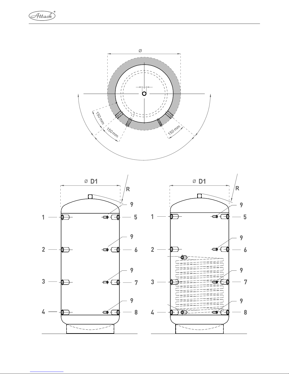
ATTACK AK: 9× socket G 1 ½", 4× socket G ½"
ATTACK AS: 9× socket G 1 ½", 4× socket G ½", 2× socket G 1" – solar circuit
KEY FOR THE ACCUMULATION TANKS
1 – Flow connection – boiler . . . . . . . . . . . . . 1 ½"
2 – Freely disposable . . . . . . . . . . . . . . . . . . 1 ½"
3 – Freely disposable . . . . . . . . . . . . . . . . . . 1 ½"
4 – Return connection – heating circuit . . . . . . 1 ½"
5 – Flow connection – heating circuit (radiators) . 1 ½"
6 – Flow connection – heating circuit (floor) . . . 1 ½"
7 – Return connection – gas, oil and pellet boiler . . 1 ½"
8 – Return connection – wood boiler . . . . . . . 1 ½"
9 – Sensor of solar system or heating . . . . . . . . ½"
AS – Flow connection of solar system . . . . . . . . 1"
RS – Return connection of solar system . . . . . . . 1"
D1 – Diameter without insulation
D2 – Diameter with insulation
TECHNICAL PARAMETERS
Tank
Solar
excha nger
Tank
Type
Energy efficiency c lass
Position 1–5
Position 2–6
Position 3–7
Position 4–8
Position RS
Position AS
L – max. length of the ele ctric
heating body
∅ D1 – Diameter without
insulation
∅ D2 – Diameter with insula -
tion of 100 mm
Height
Height with insulation of
100 mm
R – Slope dimension wit hout
insulation
Max. operating pressure (bar)
Static loss (W )
Max. operating temperature (°C)
Area of exchanger (m²)
Volume of e xchanger (l)
Max. operating pressure (bar)
Volume (l)
Weight (kg)
AK200K C 925 705 455 205 - - 550 500 700 1 140 1 190 1 157 3 65 95 - - - 204 46
AK300K C 1 110 790 4 60 210 - - 600 550 750 1 350 1 400 1 368 3 78 95 - - - 289 60
AK400K C 1 120 815 515 210 - - 700 650 850 1 380 1 430 1 402 3 87 95 - - - 405 73
AK500K C 1 4 05 1 013 621 230 - - 700 650 850 1 660 1 710 1 678 3 94 95 - - - 488 81
AK800K - 1 545 1 135 725 315 - - 84 0 79 0 990 1 8 40 1 890 1 864 3 108 95 - - - 732 109
AK1000K - 1 735 1 255 775 295 - - 840 790 990 2 030 2 080 2 052 3 127 95 - - - 915 118
AK1500K - 1 755 1 345 820 375 - - 1 050 1 000 1 200 2 095 2 145 2 142 3 162 95 - - - 1 449 201
AK2000K - 1 955 1 4 09 862 315 - - 1 150 1 100 1 30 0 2 310 2 360 2 353 3 189 95 - - - 1 980 235
AK2500K - 2 005 1 4 65 915 375 - - 1 250 1 200 1 400 2 387 2 437 2 438 3 - 95 - - - 2 435 271
AK3000K - 2 205 1 600 985 375 - - 1 300 1 250 1 450 2 596 2 646 2 643 3 - 95 - - - 2 915 363
AK4000K - 2 385 1 730 1 065 405 - - 1 450 1 400 1 6 00 2 819 2 869 2 872 3 - 95 - - - 3 819 475
AK5000K - 2 285 1 6 80 1 065 455 - - 1 650 1 600 1 800 2 770 2 820 2 845 3 - 95 - - - 4 940 578
AS200K C 925 705 455 205 205 545 550 500 700 1 140 1 190 1 157 3 6 4 95 0,9 6 10 198 63
AS300K C 1 110 790 460 210 210 610 60 0 550 750 1 350 1 400 1 368 3 77 95 1,2 7,9 10 283 83
AS400K C 1 120 815 515 210 210 610 700 650 850 1 380 1 430 1 402 3 84 95 1,5 10 10 388 103
AS500K C 1 405 1 013 621 230 230 710 700 650 850 1 660 1 710 1 678 3 92 95 1,8 11,9 10 474 118
AS800K - 1 545 1 135 725 315 315 725 840 790 9 90 1 84 0 1 890
1 864 3 105 95 2,4 15,9 10 713 157
AS1000K - 1 735 1 255 775 295 295 860 840 790 990 2 030 2 080 2 052 3 121 95 3 19,8 10 891 172
AS1500K - 1 755 1 345 820 375 375 895 1 050 1 000 1 200 2 095 2 145 2 142 3 161 95 3,6 23,7 10 1 420 265
AS2000K - 1 955 1 409 862 315 315 843 1 150 1 100 1 300 2 310 2 360 2 353 3 188 95 4,2 23,7 10 1 960 296
AS2500K - 2 005 1 465 915 375 375 1 095 1 250 1 200 1 40 0 2 387 2 437 2 438 3 - 95 4,2 27,7 10 2 410 345
AS3000K - 2 205 1 600 985 375 375 1 095 1 300 1 250 1 450 2 596 2 646 2 643 3 - 95 4,2 27,7 10 2 890 446
AS4000K - 2 385 1 730 1 065 405 405 1 125 1 450 1 400 1 600 2 819 2 869 2 872 3 - 95 5 33 10 3 779 568
AS5000K - 2 285 1 680 1 065 455 455 1 175 1 650 1 600 1 800 2 770 2 820 2 845 3 - 95 6 39,6 10 4 880 687
Page 6

1
2
3
EL EL
4
5
6
7
8
9
6
7
8
9
10
10
10
RS
AS
10
10
10
10
10
1
2
3
4
5
AF
AC
MA
CN
14°
D2
∅
D1
∅
D1
∅
R
R
100
28°
17°
17°
EL
28°
6
ACCUMULATION TANKS ATTACK HR, HRS
ATTACK HRSATTACK HR
Page 7

7
ACCUMULATION TANKS
DESCRIPTION
The accumulation tanks ATTACK HR, HRS are made from the quality steel
and serve for accumulation of the heating water as well as for preparation of
the D.H.W. by an internal enameled exchanger. The ATTACK HRS model is
accessorized with an extra exchanger to be connected to the solar system.
Tanks of this type have a built-in magnesium anode in the D.H.W. tank
to increase resistance against corrosion. The manual deaeration valve is installed in the upper part.
ATTACK HR: 9× socket G 1 ½", 6× socket G ½"
ATTACK HRS: 9× socket G 1 ½", 6× socket G ½", 2× socket G 1" – solar circuit
KEY FOR THE ACCUMULATION TANKS
1 – Flow connection – boiler . . . . . . . . . . . . . 1 ½"
2 – Freely disposable . . . . . . . . . . . . . . . . . . 1 ½"
3 – Electrical heating coil (EL) . . . . . . . . . . . . 1 ½"
4 – Freely disposable . . . . . . . . . . . . . . . . . . 1 ½"
5 – Return connection – heating circuit . . . . . . 1 ½"
6 – Flow connection – heating circuit (radiators) 1 ½"
7 – Flow connection – heating circuit (floor) . . . 1 ½"
8 – Return connection – gas, oil and pellet boiler 1 ½"
9 – Return connection – wood boiler . . . . . . . 1 ½"
10 – Sensor of solar system or heating . . . . . . . ½"
AS – Flow connection of solar system . . . . . . . . 1"
RS – Return connection of solar system . . . . . . . 1"
D1 – Diameter without insulation
D2 – Diameter with insulation
CN – Pump of the circulation tank . . . . . . . . . . ¾"
AF – Cold drinking water . . . . . . . . . . . . . . . . ¾"
AC – Hot drinking water . . . . . . . . . . . . . . . . . ¾"
MA – Magnesium anode . . . . . . . . . . . . . . . . . –
TECHNICAL PARAMETERS
Tank
Solar
excha nger
Internal
tank
Tank
Type
Position 1–6
Position 2–7
Position 3
L-max. length of th e el. heating
body
Position 4–8
Position 5–9
Position RS
Position AS
∅ D1 – Diameter without
insulation
∅ D2 – Diameter with insula -
tion of 100 mm
Height
Height with insulation of
100 mm
R – Slope dimension wit hout
insulation
Max. operating temperature (°C)
Static loss (W )
Max. operating pressure (bar)
Area of exchanger (m²)
Volume of e xchanger (l)
Max. operating pressure (bar)
Volume (l)
Max. operating temperature (°C)
Max. operating pressure (bar)
Volume (l)
Weight (kg)
HR600K
1 515 1 123 794 650 684 245 - - 70 0 900 1 754 1 854 1 841 95 99 3 - - - 160 95 6 445 157
HR800K
1 545 1 135 8 46 735 725 315 - - 790 9 90 1 806 1 906 1 898 95 105 3 - - - 160 95 6 553 157
HR1000K
1 735 1 255 1 036 735 775 295 - - 790 9 90 1 996 2 096 2 081 95 121 3 - - - 160 95 6 731 172
HR1250K
1 655 1 175 988 880 695 285 - - 950 1 150 1 948 2 048 2 064 95 142 3 - - - 160 95 6 1 079 172
HR1500K
1 755 1 345 1 072 920 820 375 - - 1 00 0 1 200 2 032 2 132 2 160 95 161 3 - - - 160 95 6 1 260 265
HR2000K
1 955 1 408 1 314 1 000 862 315 - - 1 100 1 300 2 274 2 374 2 390 95 188 3 - - - 160 95 6 1 800 296
HRS600K
1 515 1 123 794 650 684 245 245 725 700 900 1 754 1 854 1 841 95 99 3 1,8 11,9 10 160 95 6 445 157
HRS80 0K
1 545 1 135 8 46 735 725 315 315 725 790 9 90 1 806 1 906 1 898 95 105 3 2,4 15,9 10 160 95 6 553 157
HRS1000K
1 735 1 255 1 036 735 775 295 295 860 790 9 90 1 996 2 096 2 081 95 121 3 3 19,8 10 160 95 6 731 172
HRS1250K
1 655 1 175 988 880 695 285 285 850 950 1 150 1 948 2 048 2 064 95 142 3 3 19,8 10 160 95 6 1 079 172
HRS1500K
1 755 1 345 1 072 920 820 375 375 895 1 0 00 1 200 2 032 2 132 2 160 95 161 3 3,6 19,8 10 160 95 6 1 260 265
HRS200 0K
1 955 1 408 1 314 1 000 862 315 315 843 1 100 1 300 2 274 2 374 2 390 95 188 3 4,2 23,7 10 160 95 6 1 800 296
Page 8

R
AS
RS
R
90°
12°
12°
AC
AF
½"
D2
8
ACCUMULATION TANKS ATTACK TUV, TUVS
TECHNICAL PARAMETERS OF THE D.H.W. EXCHANGER
Material Stainless steel
Heated area 3,9 m
2
Volume 13 l
Connec tion 3/4"
Max. operating pressure 10 bar
ATTACK TUV ATTACK TUVS
Page 9

9
ACCUMULATION TANKS
DESCRIPTION
The accumulation tanks ATTACK TUV, TUVS are made from a quality steel
and they serve for accumulation of the heating water as well as for the D.H.W.
preparation in a water coil. The ATTACK TUVS model is accessorized with an
extra exchanger for connection to the solar system.
ATTACK TUV: 9× socket G 1 ½", 5× socket G ½", 2× socket G 1" – D.H.W.
ATTACK TUVS: 9× socket G 1 ½", 5× socket G ½", 2× socket G 1" – solar circuit,
2× socket G 1" – D.H.W.
KEY FOR THE ACCUMULATION TANKS
1 – Flow connection - boiler . . . . . . . . . . . . . 1 ½"
2 – Freely disposable . . . . . . . . . . . . . . . . . . 1 ½"
3 – Electrical heating coil (EL) . . . . . . . . . . . . 1 ½"
4 – Freely disposable . . . . . . . . . . . . . . . . . . 1 ½"
5 – Return connection – heating circuit . . . . . . 1 ½"
6 – Flow connection – heating circuit (radiators) . 1 ½"
7 – Flow connection – heating circuit (floor) . . . 1 ½"
8 – Return connection – gas, oil or pellet boiler . 1 ½"
9 – Return connection – wood boiler . . . . . . . 1 ½"
10 – Sensor of solar system or heating . . . . . . . ½"
AS – Flow connection of solar system . . . . . . . . 1"
RS – Return connection of solar system . . . . . . . 1"
D1 – Diameter without insulation
D2 – Diameter with insulation
AF – Cold drinking water . . . . . . . . . . . . . . . . 1"
AC – Domestic hot water . . . . . . . . . . . . . . . . 1"
TECHNICAL PARAMETERS
Tank
Solar
excha nger
Tank
Type
Energy efficiency c lass
Position 1–6
Position 2–7
Position 3 (EL)
L – max. length of the
elec tric heating body
Position 4–8
Position 5–9
Position RS
Position AS
∅ D1 – Diameter without
insulation
∅ D2 – Diameter with
insulation
Height
R – Slope dimension
without insulatio n
Mini. in stallation height
Max. operating tempera-
ture (°C)
Static loss (W )
Max. operating pressure
(bar)
Area of exchanger (m²)
Volume of e xchanger (l)
Max. operating pressure
(bar)
Max. operatind tempera-
ture (°C)
Area of D.H.W. exchanger
(m²)
Volume (l)
Weight (kg)
TUV500K C
1 405 1 013 771 600 621 230 - - 650 850 1 631 1 717 1 831 95
-
3 - - - - 4,54 474 157
TUV600K -
1 515 1 123 794 650 684 245 - - 700 900 1 754 1 841 1 954 95
99
3 - - - - 4,54 605 157
TUV800K -
1 545 1 135 846 735 725 315 - - 790 990 1 8 06 1 898 2 006 95
105
3 - - - - 4,54 713 157
TUV1000K -
1 735 1 255 1 036 735 775 295 - - 790 990 1 9 96 2 081 2 196 95
121
3 - - - - 4,54 891 172
TUV1250K -
1 655 1 175 988 880 695 285 - - 950 1 150 1 94 8 2 064 2 148 95
142
3 - - - - 4,54 1 239 172
TUV1500K -
1 755 1 345 1 072 920 820 375 - - 1 000 1 20 0 2 032 2 160 2 232 95
161
3 - - - - 4,54 1 420 265
TUV200 0K -
1 955 1 408 1 314 1 000 862 315 - - 1 100 1 30 0 2 274 2 390 2 474 95
188
3 - - - - 4,54 1 960 296
TUVS500K C
1 405 1 013 771 600 621 230 230 710 650 850 1 631 1 717 1 831 95
-
3 1,8 11,9 10 110 4,54 474 157
TUVS600K -
1 515 1 123 794 650 684 245 245 72 5 70 0 900 1 754 1 841 1 954 95
99
3 1,8 11,9 10 110 4,54 605 157
TUVS800K -
1 545 1 135 846 735 725 315 315 725 790 990 1 806 1 898 2 006 95
105
3 2,4 15,9 10 110 4,54 713 157
TUVS1000K -
1 735 1 255 1 036 735 775 295 295 860 790 990 1 996 2 081 2 196 95
121
3 3 19,8 10 110 4,54 891 172
TUVS1250K -
1 655 1 175 988 880 695 285 285 850 950 1 150 1 948 2 064 2 148 95
142
3 3 19,8 10 110 4,54 1 239 172
TUVS1500K -
1 755 1 345 1 072 920 820 375 375 895 1 000 1 20 0 2 032 2 160 2 2 32 95
161
3 3,6 19,8 10 110 4,54 1 420 265
TUVS2000K -
1 955 1 408 1 314 1 000 862 315 315 843 1 100 1 300 2 274 2 390 2 474 95
188
3 4, 2 23,7 10 110 4,54 1 960 296
Page 10

D2
1 ½"
1 ½" 1 ½"
90°
10°
10°
45°
45°
10
ATTACK S ATTACK SS
STRATIFIED STORAGE TANKS ATTACK S, SS
Page 11

11
ACCUMULATION TANKS
DESCRIPTION
ATTACK S – is based on the ATTACK AK type. Disk and stratified pipe
installed in the exchanger enable creation of water layers according to
the temperature. This construction ensures different temperature layers
at the inlets and outlets.
ATTACK SS – is based on the ATTACK AS and the ATTACK S types. It is
accessorized with an extra exchanger for connection to the solar circuit.
ATTACK S: 10× socket G 1 ½", 5× socket G ½"
ATTACK SS: 10× socket G 1 ½", 5× socket G ½", 2× socket G 1" – solar circuit
KEY FOR THE ACCUMULATION TANKS
1 – Flow connection – boiler . . . . . . . . . . . 1 ½"
2 – Freely disposable . . . . . . . . . . . . . . . . 1 ½"
3 – Electrical heating coil (EL) . . . . . . . . . . 1 ½"
4 – Freely disposable . . . . . . . . . . . . . . . . 1 ½"
5 – Return connection – heating circuit . . . . 1 ½"
6 – Flow connection – heating circuit (radiators) 1 ½"
7 – Flow connection – heating circuit (floor) . 1 ½"
8 – Return connection, gas, oil or pellet boiler 1 ½"
9 – Return connection – wood boiler . . . . . 1 ½"
10 – Sensor of solar system or heating . . . . . . ½"
AS – Flow connection of solar system . . . . . . . 1"
RS – Return connection of solar system . . . . . . 1"
SF – Upper solar sensor . . . . . . . . . . . . . . . . ½"
SU – Bottom solar sensor . . . . . . . . . . . . . . . ½"
D1 – Diameter without insulation
D2 – Diameter with insulation
TECHNICAL PARAMETERS
Tank
Solar
excha nger
Tank
Typ
Energy efficiency c lass
Position 1–6
Position 2–7
Position 3
L – max. length of the ele ctric
heating body
Position 4–8
Position 5–9
Position SU
Position SF
Position RS
Position AS
∅ D1 – Diameter without
insulation
∅ D2 – Diameter with insulation
of 100 mm
Height
Height with insulation of 100 mm
R – Slope dimension wit hout
insulation
Max. operating temperat ure (°C)
Static loss (W )
Max. operating pressure (bar)
Area of exchanger (m²)
Volume of e xchanger (l)
Max. operating pressure (bar)
Volume (l)
Weight (kg)
S500K C 1 405 1 013 871 700 621 230 461 1 209 - - 650 850 1 680 1 730 1 698 95 - 3 - - - 488 81
S800K - 1 545 1 135 946 84 0 725 315 491 1 340 - - 790 990 1 842 1 892 1 898 95 105 3 - - - 713 157
S1000K - 1 735 1 255 1 036 840 775 295 577 1 495 - - 790 990 2 031 2 082 2 0 81 95 121 3 - - - 891 172
S1250K - 1 655 1 175 988 1 000 695 285 565 1 415 - - 950 1 150 1 975 2 025 2 064 95 142 3 - - - 1 239 172
S1500K - 1 755 1 345 1 072 1 050 820 375 653 1 545 - - 1 00 0 1 200 2 100 2 150 2 160 95 161 3 - - - 1 420 265
S2000K - 1 955 1 408 1 314 1 150 862 315 685 1 682 - - 1 100 1 300 2 309 2 356 2 390 95 188 3 - - - 1 960 296
SS500K C 1 4 05 1 013 871 700 621 230 4 61 1 209 230 710 650 850 1 680 1 730 1 698 95 - 3 1,8 11,9 10 4 88 81
SS800K - 1 545 1 135 946 8 40 725 315 491 1 340 315 725 790 9 90 1 842 1 892 1 898 95 105 3 2,4 15,9 10 713 157
SS1000K - 1 735 1 255 1 036 84 0 775 295 577 1 495 295 860 790 990 2 031 2 082 2 081 95 121 3 3 19,8 10 891 172
SS1250K - 1 655 1 175 988 1 000 695 285 565 1 415 285 850 950 1 150 1 975 2 025 2 064 95 142 3 3 19,8 10 1 239 172
SS1500K - 1 755 1 345 1 072 1 050 820 375 653 1 545 375 895 1 000 1 200 2 100 2 150 2 160 95 161 3 3,6 23,7 10 1 420 265
SS2000K - 1 955 1 4 08 1 314 1 150 862 315 685 1 682 315 6 65 1 100 1 300 2 309 2 356 2 39 0 95 188 3 4,2 27,7 10 1 960 296
Page 12

12
4. OPERATION
Tanks accumulate heat from the heating systems for domestic or industrial use. Different types of
boilers and heating systems, renewable energy sources (heat pumps, sun collectors) or electricity
can be used to heat the water in the accumulation tank.
Heat in the tank is accumulated either by flow of the heating liquid from the heat source or by
flow of the heating liquid and the heat transfer (e.g. from solar system) through the tubular exchanger, or by warming by the electrical bodies installed inside the tank.
In the built-in D.H.W. tank or built-in instantaneous D.H.W. warming is the warmth accumulated
from the water in the accumulation tank.
5. INSTALLATION
The installation must be in conformity with the valid regulation and it can be done only by
a qualified specialist.
Faults caused by the incorrect installation, usage and operation cannot be considered as a warranty case.
5.1 CONNECTION TO THE HEAT SOURCE
Place the accumulation tank on the ground, as close as possible to the heat source. Install the insulation. Connect the heating circuits to all inlets and outlets as it is given in the table in the chapter 3.
Mount the deaeration valve at the highest place of the system and insulate all the connection
distributions.
5.2 CONNECTION OF THE ELECTRICAL HEATING BODIES
The accumulation tank can be accessorized with the electrical heating bodies. The electrical
heating bodies can be connected to the electricity mains directly (body with an own thermostat)
or through the regulator of the whole heating system.
6. PUTTING INTO THE OPERATION
Fill the heating circuits with the appropriate liquids and deaerate the whole system. Check the
tightness of all the joints and the pressure in the system.
CAUTION: Accumulation tanks HR/HRS are filling as follow. The first, will be filled inside
tank and then remainder of accumulation tank. In case of nonobservance of process the
inside tank can be damaged.
Set the parameters of the regulation of the heating system as it is given in the documentation and recommended by the producer. Check the correct function of all control and regulation elements regularly.
Quality of the heating water significantly influences the lifetime of the heating systems. Unsuitable
quality of water may cause problems like the corrosion of device and creation of the limescale, especially
Page 13

13
ACCUMULATION TANKS
on the heat-exchange surfaces of device. Quality of the heating water depends on the quality of the
water filled into the system by starting the operation and quality and amount of the water additionally
filled into the system. Quality of the water additionally filled into the system is defined in the STN 07 7401.
To prepare the D.H.W. in a built-in tank or an instantaneous system, it is necessary to install the
safety valve of 6 bar on the cold water inlet. It is also necessary to ensure the treatment of the
D.H.W. against the limescale and dirts from the water distribution network.
Hardness of water cannot exceed 5 mval / l. Warranty does not relate to the blockage of the tank
or the flow copper exchanger by a limescale.
7. MAINTENANCE
To clean the external parts of the tank you need a wet cloth and a suitable detergent. Never use
abrasive cleaners, diluents, petroleum-based cleaners, etc.
Check the tightness of joints on the flange of the HR, HRS tank at least once a year, eventually
fix the nuts. If there is untightness even after fixing the nuts, replace the sealing under the flange.
Maintenance of the accumulation tank HR, HRS concerns test and replacement of the anode rod.
The magnesium anode adjusts the electric potential inside the tank to the value preventing corrosion of the tank. Theoretical life-time of the anode takes 2 years of operation, but it changes according to the callosity and the chemical composition of water at the place, where the tank is used.
It is recommended to make a test every 6 months and in the case of need, to replace the anode rod.
This additional protection element should be considered as important.
Procedure of replacement of the anode rod:
1. Discharge approximately 1/3 of the water in the tank
Procedure: close the valve at the water inlet into the tank,
open the valve of hot water on the mixing tap,
open the discharge valve of the tank.
2. Undo the upper cover of the accumulation tank.
3. Use a suitable tool to screw the anode out.
4. Install a new anode and mount the dismantled parts back.
5. Fill the tank with water, pressurize it and check the tightness.
The anode must be replaced only by a specialized service company!
8. DISPOSAL
Packaging must be disposed following the valid prescriptions.
After expiration of the lifetime it is necessary to dispose the product in conformity with the legal
prescriptions.
Page 14

14
SPECIFICATION OF THE ANNUAL CHECKS OF THE ACCUMULATION TANKS
(performed by the authorized service)
1. CHECK OF THE STATE OF THE TANK
The accumulation tank does not need a maintenance indeed, it is only necessary to make a check
of the pressure and tightness of all the joints. In case of the water leakage from the tank or leakage
of the liquid from the heating circuits, stop the operation of device and seal the joints to ensure the
stated operating conditions.
2. CLEANING AND MAINTENANCE OF THE TANK
To clean the external parts, use a wet cloth and a suitable detergent. Never use abrasive cleaners,
diluents, petroleum-based cleaners, etc.
It is not necessary to clean the internal side of the tank, because it is connected to the closed
heating circuit with a permanent filling.
3. ELECTRICAL HEATING BODIES IF THEY ARE CONNECTED
If there are electrical heating bodies installed in the tank, it is necessary to make a check of the
function of thermostats, state of the contacts and fixation of the screws of all terminals.
Annual test no. 1 Annual test no. 2
Date: Date:
Stamp and signature of the service technician: Stamp and signature of the service technician:
Annual test no. 3 Annual test no. 4
Date: Date:
Stamp and signature of the service technician: Stamp and signature of the service technician:
Page 15

15
ACCUMULATION TANKS
NOTES:
Page 16

ATTACK, s.r.o. – 03/2017
ATTACK, s.r.o. • Dielenská Kružná 5020, 038 61 Vrútky • Slovakia
Tel: +421 43 4003 101 • Fax: +421 43 3241 129 • E-mail: kotle@attack.sk
Export – tel: +421 43 4003 103 • Fax: +421 43 3241 129 • E-mail: export@attack.sk
Výrobca ATTACK, s.r.o. si vyhradzuje právo technických zmien výrobkov bez predchádzajúceho upozornenia.
 Loading...