

Page 1

INSTRUCTIONS FOR USE
W W W . A T T A C K . S K
WALL HUNG ELECTRIC BOILER
ATTACK®
ELECTRIC EXCELLENT
Page 2

Page 3

3
Contents
1. General information
1.1 . . . . . . . . . . . . . . . . . . . . . 4Description and use
1.2 . . . . . . . . . . . . . . . . . . . . . . . 4Advantages of boiler
1.3 . . . . . . . . . . . 4Important directions and advises
1.3.1 Mounting . . . . . . . . . . . . . . . . . . . . . . . . . . . . 5
1.3.2 Putting into operation . . . . . . . . . . . . . . . . . 5
1.3.3 Boiler operation . . . . . . . . . . . . . . . . . . . . . . 5
1.3.4 Safety . . . . . . . . . . . . . . . . . . . . . . . . . . . . . . 5
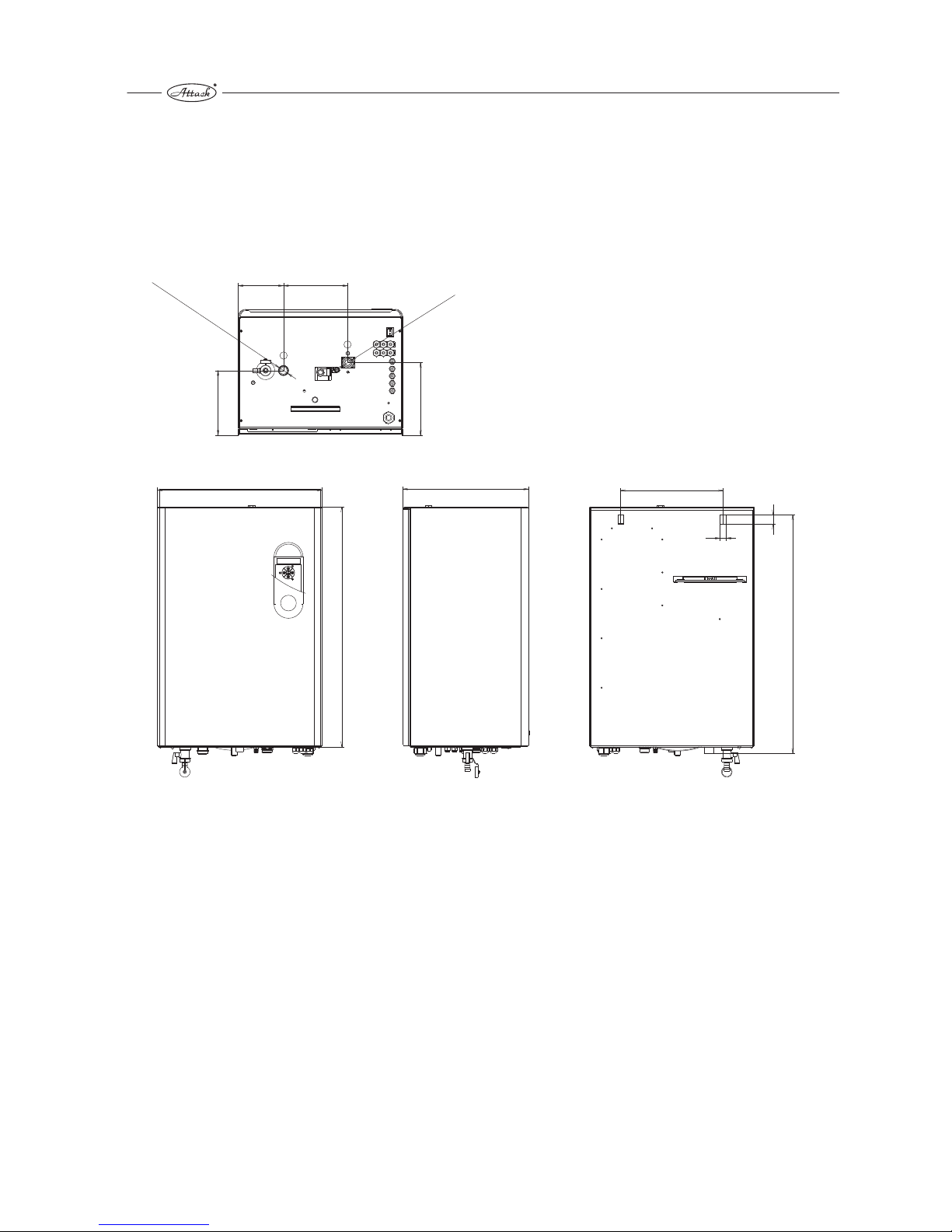
1.4 Main dimensions . . . . . . . . . . . . . . . . . . . . 6
1.5 Technical data . . . . . . . . . . . . . . . . . . . . . . 7
1.6 Main parts . . . . . . . . . . . . . . . . . . . . . . . . . 8
1.7 Description of functions . . . . . . . . . . . . . . . 9
1.7.1 Technical description . . . . . . . . . . . . . . . . . . 9
1.7.2 Principle of boiler operation . . . . . . . . . . . . . . . 9
1.7.3 Control unit and control panel . . . . . . . . . . . . 9
1.7.4 Protection function of the boiler . . . . . . . . . . 10
1.7.5 Safety function of the boiler . . . . . . . . . . . . . 10
1.8 Circuit diagram . . . . . . . . . . . . . . . . . . . . . 11
2. Boiler attendance
2.1 Control panel . . . . . . . . . . . . . . . . . . . . . 16
2.2 Switch on/off . . . . . . . . . . . . . . . . . . . . . . . . 18
2.3 Operation modes . . . . . . . . . . . . . . . . . . . 18
2.3.1 Operation mode (heating water) . . . . . . . . . . . 18
2.3.2 Operation service utility water (sanitary water) . . 20
2.4 Setting of boiler parameters . . . . . . . . . . . . 21
2.5 Breakdowns . . . . . . . . . . . . . . . . . . . . . . . . 27
3. Installation
3.1 Norms and regulation. . . . . . . . . . . . . . . . . .28
3.2 Placement of the boiler. . . . . . . . . . . . . . .28
3.3 Mounting of the boiler on the wall. . . . . . . . 28
3.4 Electroinstallation. . . . . . . . . . . . . . . . . . . . 28
3.4.1 Connection of the boiler to electric supply netw. . .28
3.4.2 Installation of the room thermostat . . . . . . . . . 29
3.4.3 Installation of mode TUV . . . . . . . . . . . . . . . . 29
3.5 Heating system . . . . . . . . . . . . . . . . . . . 29
3.6 Expansion vessel . . . . . . . . . . . . . . . . . . . . . 29
3.7 Marking of working scale . . . . . . . . . . . . . . 30
3.8 Circle pump . . . . . . . . . . . . . . . . . . . . . . . . . 30
.
4. . . . . . . . . . . . 3Termination of operation 1
5. . . . . . . . . . . . . . . . . . . . . . . . 31Maintenance
6. . . . . . . . . . . 3 Full delivery . . . . . . . . . . . . . 1
7. . . . . . . . 31Transport and warehousing
8. . . . . . . . . . . . . . . . . . . . . . . 32Claims
9. . . . . . . . . . . . . . . 32Way of liquidation
10. . . . . . . . . . . . . . . . . . . . . . . 32Enclosures
10.1 Installation of room thermostat . . . . . . . 33
10.2 Face of control unit . . . . . . . . . . . . . . . . 33
Meaning of abbreviations and used symbols
OV - heating water
TUV - service utility water (sanitary water)
ZOV - storage water tank
TMV - three ways valve
Notice pay attention
Dear customer,
You have bought a modern product – the direct heated
electric boiler ELECTRIC EXCELLENT from the company
ATTACK, s.r.o., Slovak Republic. We believe that our
Page 4

4
product will serve you good and for long time. It is
necessary for you to study whole instruction manual and
hold all the principles. The declaration of conformity was
issued by the producer according to directives
2004/108/EC, 2006/95/EC,
Basic features
®
Boilers ATTACK are electric, using water for heating. It
is electric wall-hung appliance determined for heating
of family houses or flaks with heat loss to 22,5 kW.
The boiler could be used for heating of service utility
water (sanitary water) through storage water tank.
The boiler could be remote controlled by GSM.
Advantages of your boiler
SIMPLE CONTROL – you new boiler is in operation
automatically. After boiler professional putting into
operation is not necessary any additional setting. The
boiler will adapt to conditions of your heating system
DIMENSIONS – your new boiler is really small regarding
its dimensions. You can place it anywhere where is
impossible to place another type of boilers.
REMINDER!
Your new boiler is not stay alone to be useful for your
comfort, use good outside insulation of your flat or your
house, use the room thermostat for economical
consumption of electric energy.
ATTACK, s.r.o
1. General information
1.1 Description and use
The wall hung electric boiler ELECTRA EXCELLENT is
convenient for heating in heating systems with forced
circle and for heating of service utility water (sanitary
water).
The heating of heating water takes place in a boiler drum
by means of one (EXCELLENT 08), two (EXCELLENT 15)
or three (EXCELLENT 24) heaters of a power output of
4,5 kW, 6 kW or 7,5 kW. Each heater consists of three
heating rods of a power output of 1,5 kW, 2 kW or 2,5 kW
each. Heating operation is controlled by control unit with
PID regulation. PID regulation assures high efficient
operation due to minimalizing of heating water
temperature overshoots over temperature setting. This
regulation saves also your energy consumption. The
boiler could be regulated by the room thermostat and it
also able to heat sanitary water in an independent storage
water tank connected through with 3-ways motoric valve.
1.2 Advantages of boiler
small dimensions, modern design
high efficiency 99 %
silent operation
information on the display
mode relay independent to the control unit cost
saving regarding replacement
step less regulation of boiler output with continuous
switching on/off heating elements economic
operation
rotation of heating elements ensuring elongation of
lifetime
possibility of using the boiler for under floor heating
system
breakdowns diagnostic system with display indication
information about heating system pressure thermo
manometer
operation mode Stand-by ensuring termination of
boiler operation with all protective functions:
protective functions:
antifreeze
deblocking
against overheating
against pressure lost
pump running out regulated by time or temperature
possibility of remote control with GSM
possibility of equitermic operation
possibility of connection with a storage water tank
possibility of a room thermostat connection
automatic deaerating
breakdowns statement memory
function back to factory setting.
1.3 Important instructions and
advices
Regarding installation, putting the boiler into operation
and maintenance it is necessary to observe instructions
according to concrete norms and regulations and
instructions from the producer. It is also necessary for you
to read carefully instruction manual and guarantee
conditions.
Control if the boiler in the box is completed regarding
accessories etc.
Control if the boiler type is in accordance with your
request for use.
The data stated on the type label has to be
compatible with conditions for boiler connection and
mounting.
It is not allowed for user to manipulate with parts
plumbed.
1.3.1 Installing, mounting of the boiler
Safety and economic operation of the boiler requests
a technical project made by authorized heating or
civil engineer for whole heating system.
Page 5

5
Mounting of the boiler could be carried out only by
authorized company or persons.
On the boiler and 100mm before the boiler there is
not allowed a placement of things from flammable
materials.
The boiler mounted on the wall is not able to be
moved or placed to another place.
Boiler connection is allowed only with nut with flat
ring sealing.
It is necessary to put heating water inlet with a filter
and shut off valves.
It is necessary to leave a free space on both side
walls of the boiler 100 mm and minimally 400mm
from the top for after sales service. In case that you
will not observe this request for free space you have
to pay dismantling and mounting the boiler back to
the wall and to heating system, it is not a repair paid
in guarantee period!
1.3.2 Putting into operation
Putting the boiler into operation has to be carried out
only by authorized professional company or service
person that has a valid agreement signed with the
producer. The list of these companies is enclosed.
The company or person who will put the boiler into
operation has an obligation to assure repairs of
breakdowns or defects in guarantee period. In case that
this company doesn't exist anymore, the guarantee
repair will be assured by any company from the list
closed to you.
By putting the boiler into operation the authorized
person is obligated to:
control connections of the boiler to electric supply
network and to heating system
control tightness of the boiler
control all functions of the boiler
inform the user about boiler operation, its control and
maintenance
inform the user about safety dimensions from sides of
the boiler from flammable walls and its protection
according to ČSN 061008 and ČSN 730823.
To fulfil requests for boiler safety and economic
operation it is necessary to observe below mentioned
conditions:
for boiler mounting and installing the user has to get the
permission from the company who is a distributor of
electricity in your region, control the input of the boiler if
it is in accordance with the input stated in the
permission
for mounting of the boiler it is necessary to have an
authorized technical project for heating system and for
connection of electric boiler
the boiler is able to be mounted only in an environment
according to its determination and according to the
project
manipulation, operation, using, control and
maintenance of the boilers are forbidden if it is not in
accordance with rules and directions of this instruction
manual. It is forbidden mainly to disconnect any of
safety units or elements in the boiler!!!
If the guarantee list is not filling fully, it is not valid
If you take the boiler from the colder environment
to the warmer one (for example if the outside
temperature is below 0° C or 0° C and you want to
m o un t i t i ns i d e ) , p l e a s e w a i t
approximately 2 hours.
1.3.3 Operation of the boiler
The boiler has to be controlled and used only
according to advices and instructions stated
in this instruction manual, only by adult
person who was posted in maintenance of
the boiler. Putting the boiler into operation will made by
authorized service person during the heating test.
Any manipulation, operation, using and maintenance of
the boiler, which is not in accordance with instructions
and advices stated in this instruction manual, is
inadmissible. The producer is not responsible for
damages caused by wrong using and maintenance of
the boiler.
The producer recommends periodical service controls
of the boiler 1x per year before heating season. The
service control could be done only by a professional
authorized service company or person. The list of
service control steps recommend to be controlled
before heating season you will find in the chapter
“maintenance”.
The producer allows only room thermostat connection,
if the room thermostat has with potentional-free outlet
connection. The authorized service person is
responsible during putting the boiler into operation to
fill and sign guarantee card.
If you find any breakdown or any defect on an electrical
part of the boiler, please, don´t repair it by yourself,
disconnect the boiler from the electric supply network
and ask for after sales service person.
It is not allowed to use the boiler ELECTRIC-EXCELLENT
for another purposes than is stated in this instruction
manual.
1.3.4 Safety
Fire instructions:
Disconnect the boiler from the electric supply
network and take out it out of its operation according
to possibilities.
Extinguish fire using pulverized or
snows extinguish appliance flammable
and explosive materials
Don't stock any flammable and explosive
things closed to the boiler (for example
paper, colours, chemicals etc.)
1.7 Description of function
1.7.1 Technical description
The boiler is designed according to valid norms
Page 6
6
450
656
345
280
26
16
652
124 176
177
199
G3/4
G 3/4
1.4 Main dimensions
Dimensions in mm.
outlet of heating water
inlet of heating w
ater
Page 7

7
1.5 Technical data
2 x 3 x 1,5
Power output of 1 heating rod in kW
3 heating rods
2 x heater
* Y - connection
**Supply lead has tobe proposed in preference in conformity with the norms.
***
Boiler type
ELECTRIC 15
Electric parameters
EXCELLENT
Total electric input kW 15
Nominal heating output kW 15
Heater power output 2x3x2,5
Nominal current A 3x24
Electric network* V
Electric network V
Nominal current max. A 3x24
Pump input W
Main circuit breaker A 3x25
Nominal current of control fuse A
Enclosure IP
Mechanical life time of relay Electrical life time of relay
Width mm 450
Height mm 656
Depth mm 345
Boiler weight without water kg 38
Min. working overpressure of heating system
bar
Max. working overpressure of heating system
bar
Operation overpressure recommended kPa/bar
Circle pump Maximal temperature of heating water °C
Water volume of whole boiler l
Environmental kind ČSN 332000-3 Efficiency by nominal output %
Supply cable CYKY** mm
2
5x4
Supply cable AYKY** mm
2
5x6
Expansion vessel l
Surrounding temperature °C
Warehousing and transport temperature °C
Electromagnetic temperature Humidity %
Measuring accuracy % < 1
Accuracy of boiling water regulation °C ± 1
ELECTRIC 24
EXCELLENT
22,5
22,5
3x3x2,5
3x36
3x36
3x40
450
656
345
39,5
5x6
5x10
< 1
± 1
Regulation type -
Cascade Service plug Number of boilers in cascade max. -
Unit
50/60/70
0,315
Mechanical parameters
1 000 000 cycles
40
0 ÷ 90 without condensation
Regulation
Expanding temperature of thermostat
blocked, opened-closed systém
°C 100
10,6
normal AA5, AB5
99
3x230/400V+N+PE/50 Hz*
8
0 ÷ 40
-30 ÷ + 70
EN 55014-1(2006)
Environmental requests
0,4
3
100/1
UPM3 FLEX AS 15-70
80
250 000 cycles, 16 A, 250 V
PI
Remote control
with cascade controller
6 PIN
according to the cascade controller
1x230V+N+PE/50 Hz
450
656
345
36,5
5x2,5 / 1x6
5x4 / 1x10
< 1
± 1
ELECTRIC 08
EXCELLENT
7,5
7,5
3x2,5
3x12 / 1x36
3x12 / 1x36
3x16 / 1x40
Page 8
8
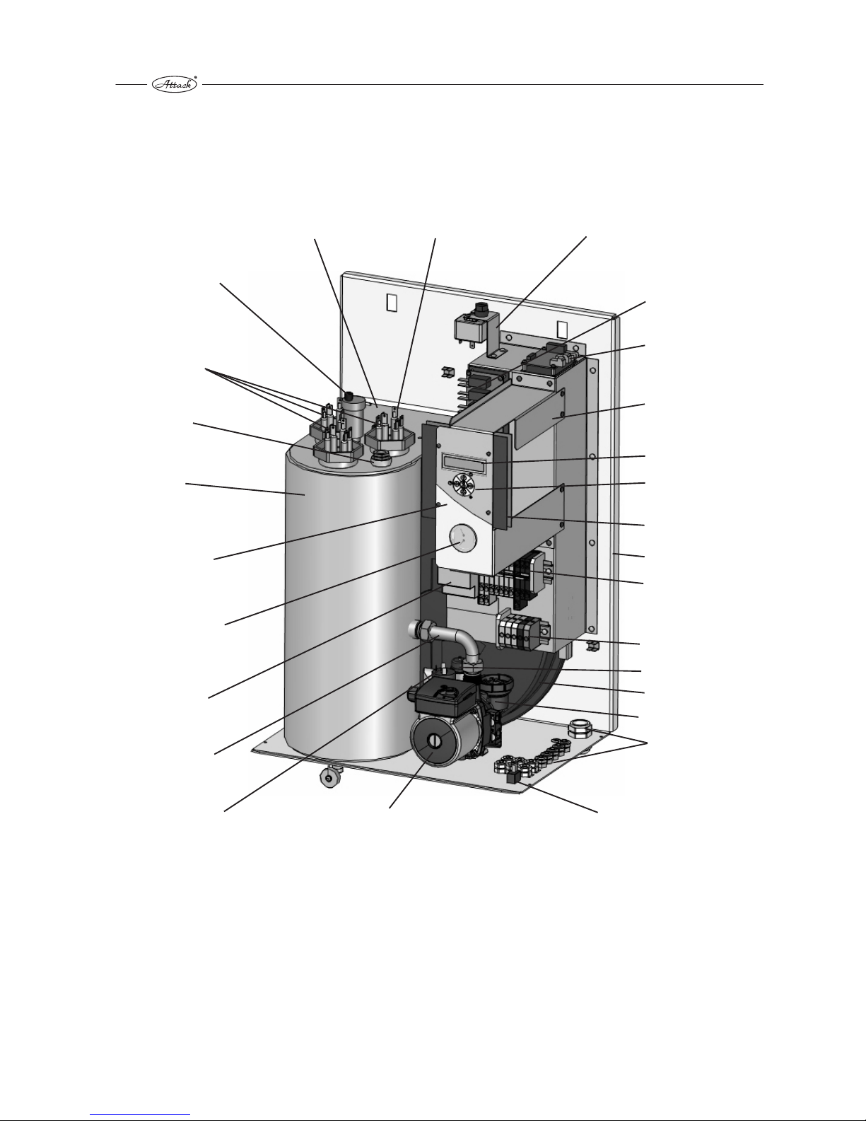
1.6 Main parts
boiler heating sensor
emergency thermostat
mode relay
mode sanitary water
control unit holder
display
touch control buttons
control unit
frame of the boiler
switchboard X2
switchboard X1
safety valve
expansion vessel
thermomanometer
sensor
cables bushing
main switcher on/off
pump
pressure switcher
inlet pipe
safety contactor
thermomanometer
control panel
insulation of boiler
body
reservoir of emergency
thermostat
heating elements
deaerate valve G3/8”
boiler body
Page 9
9
and rules ČSN EN and IEC. The safety of the boiler, energy
saving and sound was important matter during the boiler
designing.
1.7.2 Principle of boiler operation
The insulated boiler body with volume 10,6 l is a reservoir
where water is heated by electric heating elements
according to the boiler type, by one (08 kW), two (15 kW)
or three (24 kW). Depending on the actual heat
requirement, individual heating rods are connected, each
of them having a power output of 1,5 kW for Comfort 05
and Comfort 09 (1 heating rod = 1,5 kW, 6 heating rods 9
kW), a power output of 2 kW for Comfort 06, Comfort 12
and Comfort 18 (1 heating rod 2 kW, 9 heating rods 18 kW)
or a power output of 2,5 kW for EXCELLENT 15 and
Comfort 24 (1 heating rod = 2,5 kW, 9 heating rods 22,5
kW). Circulation of water is through the pump. Safety of
boiler operation is monitoring by several independent
sensors. Whole heating process and pump operation is
controlled by the control unit with display and push touch
control buttons. The button 0/1 is for switching off the
boiler out of operation.
1.7.3 Control unit and control board
Control unit has several functions which assure basic
characteristics, mainly:
safety functions assure protection against the of health
and property
user's functions functions set by the user
operation functions internal functions of control unit
import for sound operation of the boiler, but un-get-atable for the user
Control unit could be in below mentioned modifications:
basic only for heating = control unit + mode relay
for heating and heating of sanitary water = control unit
+ mode relay + mode TUV (sanitary water)
for heating with GSM remote control = control unit +
mode relay + mode GSM
for heating and heating of sanitary water with GSM
remote control = control unit + mode relay + mode TUV
(sanitary water) + mode GSM.
Control unit works with below mentioned inlet signals:
temperature of heating water (sensor NTC)
outside temperature (sensor NTC)
room temperature (sensor NTC)
temperature of sanitary water (sensor NTC) only if the
boiler has connected TUV (sanitary water) sensor
switching on signal of sanitary water heating 230 V
(only if the boiler has TUV (sanitary water) mode
room thermostat signal potentional free switcher
signal of relay lightening in the first level potentional
free switcher
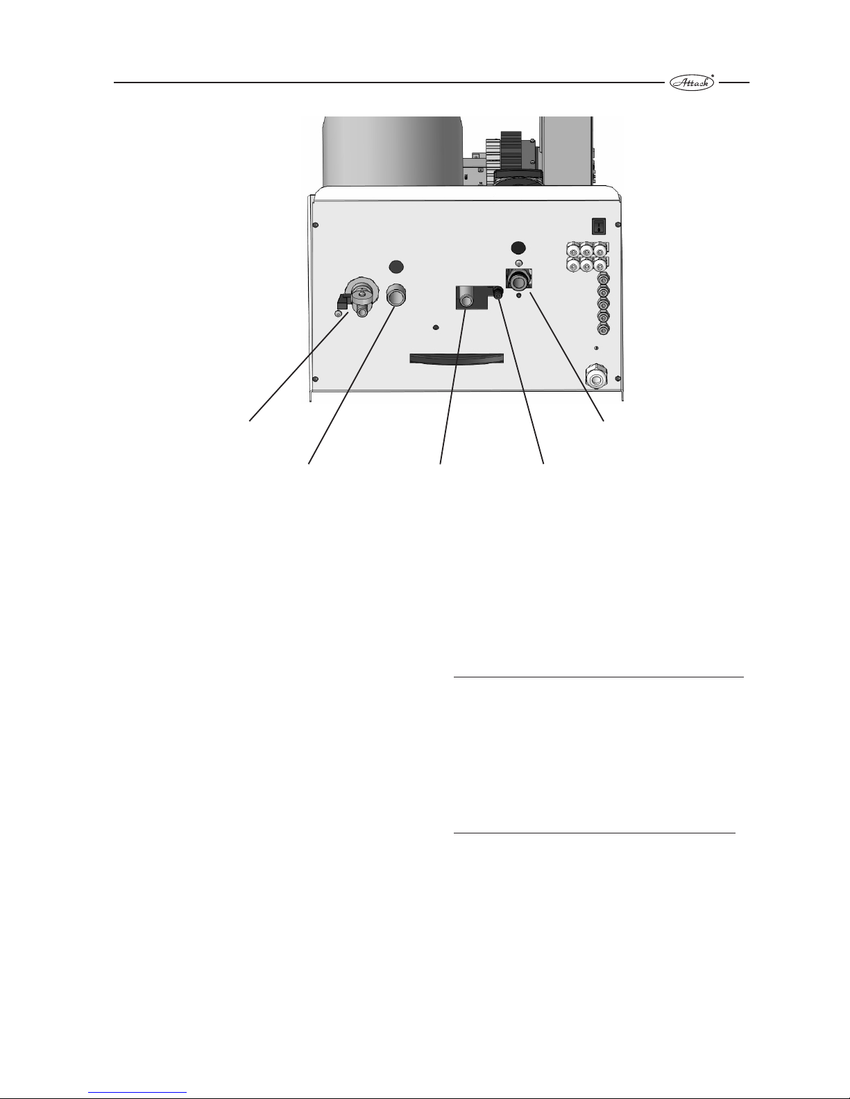
blow off valve of the boiler
body
outlet of heating wate
(warm)G 3/4”
outlet of safety valve
blow off valve of th
pump
inlet of heating water
(cold) G 3/4”
Page 10

10
signal of relay lightening in the second level
potentional free switcher
HDO (mass remote control) signal potentional free
switcher
signal HDO (mass remote control) activation of
“working zero” N
breakdown signal of floor overheating potentional
free switcher
breakdown signal of overheating 230 V
breakdown signal of pressure loss 230 V
signal of GSM mode
Control unit controls:
mode relay heating elements
mode relay pump
mode TUV (sanitary water) three ways valve for TUV
1.7.4 Antifreeze protection of the boiler
Antifreeze protection of the boiler
This function protects the boiler against freeze and is
active in the mode STAND-BY.
Circulation pump and the boiler are in operation, if
temperature of heating water decreases below 5 °C. In
this case the boiler assures minimal level o heating and
the system is mildly warm, the boiler heats to 15 °C
temperature of heating water and after that the boiler
set back to mode that it start to operate from. Pump
running of is active.
In case that the boiler is in the summer mode
(permanent heating of storage water tank) and the
temperature of heating water decreases below 5 °C
then the antifreeze protection function is activated for
heating system, after the boiler catch the temperature
15 °C, then the 3-ways valve go back to the position for
heating of sanitary water and pump running of is also
active.
If the boiler is switched off or out of electric
supply, this function is not active.
Unlocking protection of heating system
It is active at all times if the circulation pump or
3-ways valve is more than 24 hours out off
operation to protect blocking of the pump or
the valve due to its small parts. This function
avoids blocking of the pump rotor in mode
STAND-BY and elongates its lifetime.
The pump works 1 time per day for 10 s.
1.7.5 Safety function of the boiler
Control unit
The control unit is designed according to valid EU norms
and is certified.
The control unit has a protection against below and
over voltage
The control unit is protected by system Watch-Dog-
Timer with time 512 ms against its processor “blocking”.
In case that the processor is blocking the automatic
reset function is activated and then the program is
going with all parameters set from the point where it
was broken
Protection against overheating
The boiler has an emergency thermostat set for 100 °C.
In case of boiler overheating heating elements are put
out of operation independently to the control unit. This
breakdown is signaling on the display as a critical
breakdown No. 5.
This breakdown could be repaired only by authorized
service man.
Protection against lost of heating water pressure
The boiler equipped with a pressure switcher which
control minimal pressure in heating system 0,4 bar,
when the function reliability of deaerate valves is
assured, it means that the boiler has sufficient volume
of water.
In case of lost of heating water pressure below 0,4 bar
the boiler signs the critical breakdown No. 4 and
heating elements are put out of operation
independently to the control unit.
This breakdown could be repaired after the control of
tightness of water ways and after water filling over 0,4
bar. After that the boiler is automatically reset and
returned to normal operation.
Boiler protection against over and below voltage
in supply electrical net
The control unit is equipped with function assuring
putting the boiler out of operation if the voltage is below
150 V or over 250 V. This stage is marked on the display
like a critical breakdown No. 8. Below voltage is not
marked on the display.
When the voltage is OK = in the scale 150 250 V, the
boiler returns to normal operation.
Boiler protection against overpressure of heating
water
The boiler pump is equipped with pressure safety valve
set for 3 bars. In case of the overpressure more than 3
bars the leakage of water occurs from the valve till the
pressure of water in heating system is not below
maximal requested level.
This valve is in its operation automatically.
Page 11
11
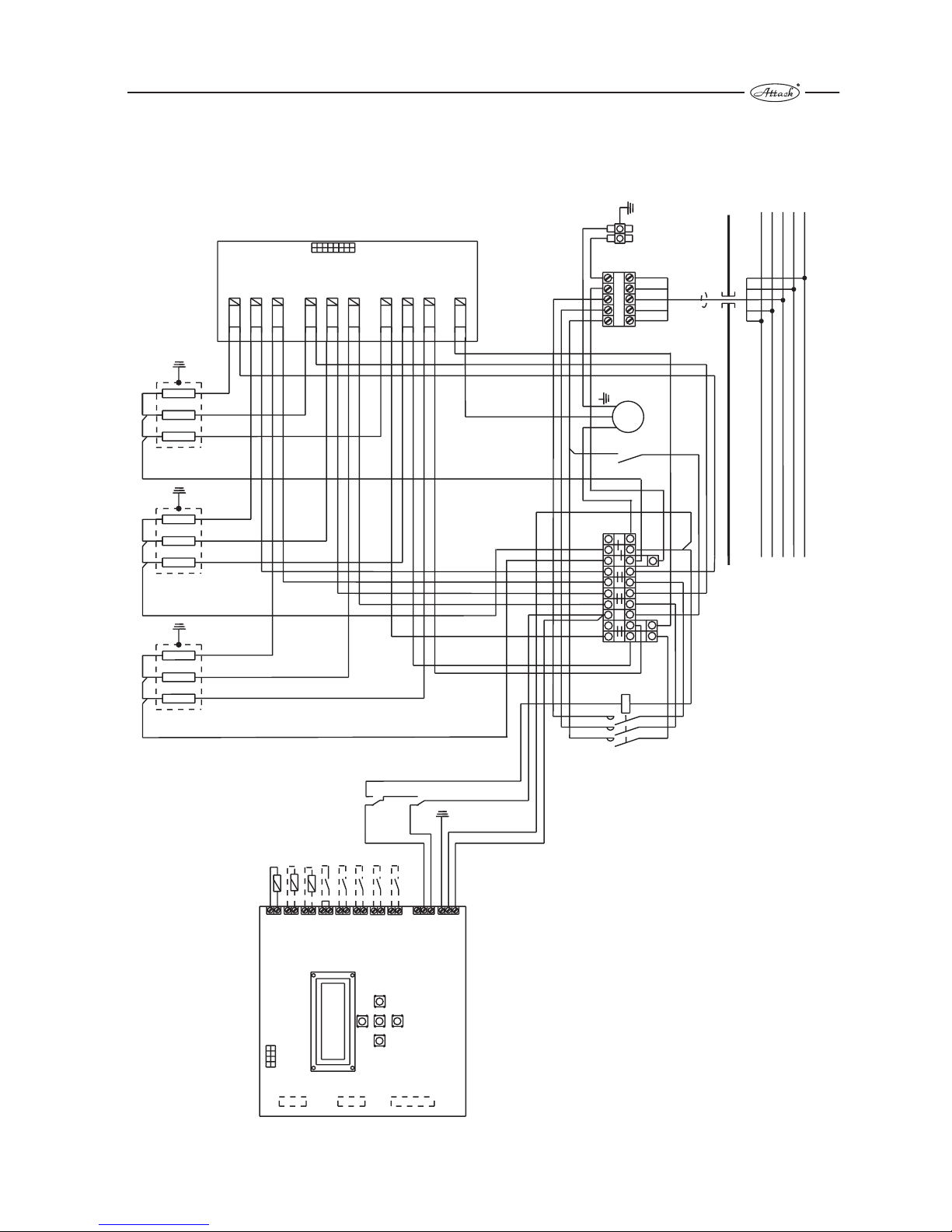
Circuit diagram for connection of the boiler EK18K, EK24K to supply electrical net 3x230V/400V
1.8 Circuit diagram
Legend:
NTC OV -
NTC sensor heating water
NTC OUT
-
NTC outside temperature sensor
NTC ROOM - NTC room temperature sensor
TER -
room thermostat 24V
FLOOR -
underfloor heating
nd
2.ST
-
external input lightening control 2 level
st
1.ST
- external input lightening control 1
leve
l
HDO -
mass remote controlí
GSM - GSM modem
HT
-
emer
gency thermostat
TS
-
pressure switcher
TUV -
service utility water (sanitary water)
KM1 -
contactor
X1, X2 - switchboard
HV -
main switcher
Č - pump
ZM -
earthing bridge
PE -
protective conductor
N -
working” conductor
L
-
phase conductor
TT1 -
heating element 1
TT2 -
heating element 2
TT3 -
heating element 3
L
N
PE
TS/230V
HT/230V
HDO/230V
HDO
FLOOR
2.ST
1.ST
TER
NTC OV
NTC OUT
NTC ROOM
1
3
5
A1
2
4
6
A2
TT1
TT2
TT3
L1
L2
L3
N
PE
1
5
1a
10a
1
1b
TT1.3
TT2.3
TT3.3
TT1.2
TT22
TT3.2
TT1.1
TT2.1
TT3.1
PUMP
mode relay
control unit
KM1
Č
ZM
TS
HT
C
X2
X1
HV
2
1
0
NC
NO
L1
L2
L3
N
PE
1
2
PG21
L
Service
GSM
TUV
REL
connection with control un
it
.
Remarks: clamps 24 V of the room thermostat ar
connected through from the factory
Connection
TUV ZOV (sanitary water
, storage water tank)
switchboard X2, clamps 2a, 10a.
N
10
TT1.3
TT1.2
TT1.1
TT2.3
TT2.2
TT2.1
TT3.3
TT3.2
TT3.1
Page 12

12
Circuit diagram for connection of the boiler EK09K,EK12K, EK 15K to supply electrical net 3x230V/400V
Legend:
NTC OV -NTC sensor heating water
NTC OUT
-
NTC outside temperature sensor
NTC ROOM -
NTC room temperature sensor
TER -
room thermostat 24V
FLOOR -
underfloor heating
nd
2.ST
-
external input lightening control 2
level
st
1.ST
- external input lightening control 1
leve
l
HDO -
mass remote controlí
GSM -
GSM modem
HT
-
emergency thermostat
TS
-
pressure switcher
TUV -
service utility water (sanitary water)
KM1 -
contactor
X1, X2 -
switchboard
HV -
main switcher
Č -
pump
ZM -
earthing bridge
PE -
protective conductor
N - working” conductor
L
-phase conductor
TT1 -
heating element 1
TT2 -
heating element 2
Remarks: clamps 24 V of the room thermostat ar
connected through from the factory
Connection
TUV ZOV (sanitary water
, storage water tank)
switchboard X2, clamps 2a, 8a.
control unit
mode relay
connection with control un
it
.
Page 13

13
Circuit diagram for connection of the boiler EK 05K,Ek 06K, EK 08K to supply electrical net 3x230V/400V
Legend:
NTC OV -
NTC sensor heating water
NTC OUT
-
NTC outside temperature sensor
NTC ROOM -
NTC room temperature sensor
TER -
room thermostat 24V
FLOOR -
underfloor heating
nd
2.ST
-
external input lightening control 2
level
st
1.ST
- external input lightening control 1
leve
l
HDO -
mass remote controlí
GSM -
GSM modem
HT
-
emer
gency thermostat
TS
-
pressure switcher
TUV -
service utility water (sanitary water)
KM1 -
contactor
X1, X2 -
switchboard
HV -
main switcher
Č -
pump
ZM -
earthing bridge
PE -
protective conductor
N -
working” conductor
L
-
phase conductor
TT1 -
heating element 1
Remarks: clamps 24 V of the room thermostat ar
connected through from the factory
Connection
TUV ZOV (sanitary water, storage water tank)
switchboard X2, clamps 2a, 6.
control unit
connection with control un
it
.
Page 14

14
Circuit diagram for connection of the boiler EK 05K, EK 06K, EK 08K to supply electrical net 1x230V
Legend:
NTC OV -
NTC sensor heating water
NTC OUT
-
NTC outside temperature sensor
NTC ROOM -
NTC room temperature sensor
TER - room thermostat 24V
FLOOR -
underfloor heating
nd
2.ST
-
external input lightening control 2
level
st
1.ST
- external input lightening control 1
leve
l
HDO -
mass remote controlí
GSM -
GSM modem
HT
-
emer
gency thermostat
TS
-
pressure switcher
TUV - service utility water (sanitary water)
KM1 -
contactor
X1, X2 -
switchboard
HV -
main switcher
Č -
pump
ZM - earthing bridge
PE -
protective conductor
N -
working” conductor
L
-
phase conductor
TT1 -
heating element 1
Remarks: clamps 24 V of the room thermostat ar
connected through from the factory
Connection
TUV ZOV (sanitary water
, storage water tank)
switchboard X2, clamps 2a, 6.
control unit
mode relay
connection with control un
it
.
Page 15

15
Circuit diagram TUV ZOV (sanitary water, storage water tank) of the boiler EK 24K
Legend:
NTC OV -NTC sensor heating water
NTC OUT
- NTC outside temperature sensor
NTC ROOM - NTC room temperature sensor
TER - room thermostat 24V
FLOOR - underfloor heating
nd
2.ST
- external input lightening control 2
level
st
1.ST
- external input lightening control 1
leve
l
HDO -mass remote controlí
GSM - GSM modem
HT
-
emer
gency thermostat
TS -
pressure switcher
TUV - service utility water (sanitary water)
KM1 -contactor
X1, X2 -
switchboard
HV - main switcher
Č - pump
ZM - earthing bridge
PE - protective conductor
N - working” conductor
L
-phase conductor
TT1 - heating element 1
TT2 - heating element 2
TT3 - heating element 3
Remarks: clamps 24 V of the room thermostat ar
connected through from the factoryConnection
TUV ZOV
(sanitary water
, storage water tank)
switchboard X2, clamps 2a, 10a.
control unit
mode relay
connection with control un
it
.
THER.TUV
1 2 N L3
orange
green
PE
Not included
Connection of DHW tank thermostat
TUV
Module TUV
Connection control unit
TMV
TMV - three way vale
Page 16

16
2. Maintenance
2.1 Control panel
information display
- temperature setting in
the reference room
change of the requested
parameter -
change of the requested
parameter +
- sanitary water temperature
setting
- information about
instantaneous stage
- going to mode STAND-BY
- parameters enter
- selection confirmation
i
0
0 C
0
--0 C
0
--0 C
ZI
22,5 kW
- going from the mode
STAND-BY the mode of heating
+
-
Thermomanometer
Page 17

17
Display
- Information display
- use for editing of instantaneous values of the electric boiler
- enter to information display is available after long (approx. 4s) pushing or 4x short pushing
0
TVS + 10 C
0
OVP35 C
CSQ:20
PP:3
instantaneous temperature of outside sensor
( )only if it is connected
requested and calculated temperature of the heating water
( )according to an equithermic curve
last breakdown in the boiler memory
GSM signal intensity (1- 30)
( )only if GSM mode is connected
- Basic information displayed
0
40 C
0
55 C
0
21 C
WI
10 kW
instantaneous temperature
of heating water
instantaneous temperature of sanitary
water in the storage water tank
(only if the boiler has TUV (sanitary water) mode
and TUV (sanitary water) sensor connected)
instantaneous temperature in referring room
(in case of reffering room sensor connection)
pump operation
- marking is lightining and the pump is in an operation
- marking is not lighting and the pump is switched off
signalizing of instantaneous stage of the boiler
- the boiler is in an operation of storage water tank heating
( )only if the boiler has TUV mode
- the boiler is in and operation of heating water
signalizing of instantaneous stage of GSM
( )only if the boiler has GSM mode
- - GSM in an operation
- @ - receiving/sending SMS
signalizing of the instantaneous boiler mode
WI - mode “WINTER” (heating water and
storage water tank heating)
SU - mode “SUMMER” (only storage water tank heating,
if the boiler has TUV (sanitary water) mode connected)
instantaneous output
of the boiler in kW
- S - (Soft start) SOFT START - see parameter P11
HDO
- vysoký tarif
- nízký tarif
Page 18

18
2.3 Modes
Important information for setting
during editing “help” is lighting in the low line for the
value to be set
during the first pushing of each button the editing is not
active
in delay in setting more than 10 s the editing is without
the change, it means that the setting is going back to
the starting position (only if the editing was not
confirmed )
each value set has to be confirmed by button .
if the value setting is not wanted or wrong (for example
entering the parameters setting), wait 10 s and the
boiler is automatically going back to starting basic
display or it is also possible to “enter” the parameter by
pushing the button , .
By holding the button , the setting value will
automatically rolls up or down
In case of wrong parameters setting it is possible to go
back to “factory setting” according to these steps:
switch off the boiler using the main switcher, push
together and switch on the boiler. On the
display there is “reset of factory parameters” and after
OK is displayed then the parameters are according to
factory setting.
Main operation modes
Operation mode “winter”
on the display there is “WI”
this operation mode is active always when the
temperature of heating water is set (it means the
operation mode “SU” is not lighting). In this operation
mode the boiler is heating the system and also the
storage water tank (if it is connected through)
Operation mode “summer”
on the display there is “SU”
this mode is possible to activated by reducing the
temperature of heating water using the button - below
25° C and confirmed this by .In this operation mode
the boiler is heating only the storage water tank (3ways valve is permanently in position in position
“tank”). It is possible to go from this operation mode to
operation mode “Winter” by increasing of heating water
temperature using and confirm it by .
Operation mode “stand by”
on the display there is
this operation mode is activated by long pushing (3 s)
the button and deactivated by short pushing .
Concerning this operation mode there are only active
protective functions described in the chapter 1.7.4
2.3.1 Mode heating (heating water)
on the display there is the symbol
this manual mode is active in operation mode
“WINTER” “WI”“
+
-
+
-
+
2.2 The boiler switching ON/OFF
Use the switcher 0/1 placed on the right corner of bottom side of the boiler (see the picture 1.6 Main parts)
On the display there is displayed introductory information after boiler's switching on.
E - KOMFORT: 22,5 kW
TUV: NE VER.1.20
- electric boiler ELECTRIC EXCELLENT with output 22,5 kW
- TUV mode is not connected, SW version 1.20
Switchboard of the boiler and inlet conductors and clamps of the contactor and inlet conductor
of the switcher are under voltage!
Disconnect the boiler from the main electric inlet supply!
Example::
Page 19

19
Without the room thermostat connected
Regulation is depended on the temperature of boiler water
requested by the user and hysteresis set by the parameter
P20 in the scale 1 - 10 °C. (This parameter could be set
only by authorized service person).
Steps for temperature setting of heating water:
Set the temperature requested by pushing , on the
control panel , on the display is temperature and “OV
TEPLOTA” and confirm by .After confirmation you will
go back to the basic display. The boiler is now heating to
the temperature requested by you. The scale of
temperature setting is 25 80 °C (regarding the setting
below the temperature value 25 °C the marking of
operation mode “SUMMER” = “SU” is lighting, going back
to heating mode is possible only by increasing the
temperature of heating water by the button ) .
If you don't confirm the value during editing till. 10 s, the
boiler is automatically goes back to the previous setting.
We recommend you to use the room thermostat for
economical operation of your heating system
With the room thermostat
In case that the room thermostat is connected the
regulation of temperature is the same as in case
without the room thermostat connected till the moment
when the request for heating is stopped by the room
thermostat.
With the room sensor connected (on the display there is
marked by the symbol .
In case that the room sensor is connected (the order
number of set is 4050485) the boiler is heating according
to the temperature in a reference room with hysteresis 1
°C. Actual temperature in the reference room is displayed
under the symbol .The room sensor is connected on the
clamps of the control unit marked NTC ROOM.
Steps for setting of temperature in a reference room
Press the button , on the control panel, for setting of the
temperature requested press for its increasing or
for its decreasing and confirm it by . After this
confirmation you will go back to main display.
Temperature could be set in scale from 5 to 35 °C, if the
temperature is decreased below 5°C the regulation
function is switched off on the basis of reference room
temperature. The boiler is controlled by the same way as
in previous 2 samples without the importance of the
temperature in reference room. The temperature will not
be shown on the display.
Remarks: if you have reference room temperature
regulation activated then this regulation is priority (and
the boiler will not reply to room thermostat).
Steps for setting of temperature in a reference room with
GSM modem (Only if you have GSM modem order No.
9566.2010 connected to the boiler)
The temperature in a reference room it is possible to set
also like a remote control through SMS in a format
example *22 (star, temperature in °C without spaces)
according to the way described in a instruction manual of
GSM modem.
GSM module works only in the nets
with standardized GSM protocol.
With equithermic regulation
equithermic regulation is not depended on instruction
from control elements of the boiler, it is determined
only for setting the temperature of heating water on
the basis of outdoor temperature.
this mode it is possible to be activated by connection of
outdoor sensor (set of outside sensor order No. 4841815
of control unit “NTC OUT”) and setting of equitermic
curve regulation is done by the parameter P8.
+
-
+
+
-
4
5
5
6
1 - boiler
4 - heating system
5 - closing valve
6 - filter
1
1 -boiler
4 - heating system
5 - closing valve
6 - filter
10 - temperature sensor
in reference room
4
5
5
6
10
1
9
4
5
5
6
1 - boiler
4 - heating system
5 - closing valve
6 -filter
9 -room thermostat
1
Page 20

20
Temperature of heating water for heating will be
automatically calculated on the basis of the outdoor
temperature according to the curve chosen and change
of starting point (parameter P9) without dependency of
heating water temperature setting.
Steps for setting are described in a chapter “Setting of
parameters”.
Disconnecting of equitermic regulation is necessary to
carry out with the parameter P8 and with decreasing of
the equitermic curve number value under the value “1”
till the text “NE” is displayed.
2.3.2 Mode TUV (sanitary water) is displayed
This mode is able to be activated after connection of
TUV mode order No. 9566.2000,
This mode is active in operation mode “summer”,
“winter” and is activated after request for heating
into the storage water tank.,
Temperature of water in the storage water tanks is
controlled directly by connection of TUV sensor in
the TUV mode or indirectly with storage thermostat
which gives information to the boiler heat/don´t heat
through the connection of connection of contactors
to the clamps on the mode TUV.
With connection of TUV sensor
1 - boiler
2 - storage water tank
3 - 3-ways valve
4 - heating system
5 - closing valve
6 - filter
7 - back flap
8 - treatment place
for water
9 - room thermostat
10 - reference room
temperature sensor
11 - consumption place
12 - safety valve for TUV
(sanitary water)
13 - expansion valve
14 - sensor of storage
water tank
9
M
AB
A
B
13
2
3
4
5
6
7
8
11
12
14
5
5
5
5
10
1
curve No.
1
2
3
20
25
4
5
6
7
9
10
65
70
75
80
85
30
35
40
45
50
55
60
4
5
678
9
10
1
2
3
outside temperature (°C))
temperature of heating water (°C))
equitermic curves of control panel
curve No.
curve No.
curve No.
curve No.
curve No.
curve No.
curve No.
8
curve No.
curve No.
Below mentioned equitermic curves are calculated for room reference temperature 20 °C.
Page 21

21
the boiler will hold the temperature set in the storage
water with hysteresis set by the parameter 21 in a scale
1 10 °C (Remarks this parameter is able to be set only
by service authorized person).
Steps for setting of TUV (sanitary water) temperature:
Press , on the control panel and for setting of the
temperature requested press for increasing and
for decreasing of temperature and confirm it by .After its
confirmation you go back to the main display. Temperature
is able to be set in a scale 30 - 65 °C, if temperature is
reduced below 30 °C then the boiler will switch off heating
of TUV. On the display there is displayed “VYP” instead of
temperature value. The boiler will not answer to the
temperature in the storage water tank.
With connection of thermostat clamps to the storage
water tank
The boiler is controlled by potential-free signal ON/OFF
connected to the clamps of TUV mode. In case of the
request for TUV/sanitary water heating “ON” the
temperature regulation is carry out for the before set
temperature 80 °C. After termination of operation the
boiler automatically goes back to the mode before
setting. Going back to this mode is automatically, it is
not possible to active it by a user.
Attention!
In the case of combination of boiler (hot water
heating and floor heating it is always
necessary to intall proctectionagainst the
overheating of the floor heating (f.e. mixing
valve).
2.4. Setting of par ameter and
functions of the boiler
Parameters P20 to P28 and P33, P34 are possible to be
displayed and to be set after rebuilding of service
jumper on the back side of the control unit.
Change in setting of the boiler could be
carried out only by authorized service
person!
After cover removing there is threat of
emergency of electric shock!
For your easy orientation and setting is enclosed
a help table of parameters:
+
-
1 - boiler
2 - storage water tank
3 - 3 ways motoric valve
4 - heating system
5 - closing valve
6 - filter
7 - back flap
8 - treatment of sanitary
water
9 - room thermostat
10 - reference room
temperature sensor
11 - consumption place
12 -safety valve
TUV/sanitary water
13 - expansion vessel
15 - thermostat of storage
water tank
M
AB
A
B
13
2
3
4
5
6
7
8
9
11
12
5
5
5
5
10
15
1
Page 22

22
max. output
according to parameter P35
max. boiler output
according to parameter P35
Parameter
marking
Information/value
displayed in English
Importance Setting value
Factory
setting
Autorization
Min.
version of
the boiler
- HW setting
Setting of heating water tempeature, going to
"summer" opeation mode under 30 °C (symbol of
summer = tap)
30 to 80, step 1 60 User 1
- DHW setting
Setting of sanitary (domestic hot water) tempeature,
going to switch off mode under 30°C ("-" is lihtening
on the display instead of temperature value)
30 to 65, step 1 50 User 2
- Room setting
Setting of temperature requested in reference room
under 5°C, termination regulation on basis of temperature in reference room ("-" is lightening on the display
instead of temperature value)
5 to 35, step 1 Ooff User 1+A2
P1 Language Language CZ, EN,FR,SK,DE EN User 1
P2 Backlighting Permanent backlightening of display YES, NO Yes User 1
P3 Pump runout set Pump running out Time, temperature Temperature User 1
P4 Time pump runout Time of pump runing out 1 to 30, step 1 min 10 User 1
P5
Temperature pump
runout
Temperature of pump running out 25 to 70,step 1°C 40 User 1
P6 Floor temp. limit Underfloor heating - temperature limitation No, 20 to 55, step 1°C No User 1
P7 Antifrost Antifrost protection YES, NO Yes User 1
P8 Equithermic curves Selection of equitermic curve No, 1 to 10, step 1 No User 1+A1
P9
Equithermic curve - start
Moving of start point of equitermic curve 20 to 30 °C, step 1 °C 20 User 1+A1
P10 Tempering Tempering - outside temperature No, 0 to 10, step 1°C No User 1+A1
P11 Soft start temp. Temperature setting delay with soft start No, 30 to 80, step 1 °C 40 User 1
P12 Soft start time Time settling delay 1 to 60, step 1 min 1 User 1
- - - - - - -
- - - - - - -
- - - - - - -
- - - - - - -
- - - - - - -
P18 P-constant Regulation constant P 0 to 99, step 1% 50 Producer 1
P19 I-constant Regulation constant I 0 to 99, step 1% 50 Producer 1
P20 HW hysteresis Hysteresis of heating water temperature 1 to 10, step 1°C 5 Service 1
P21 DHW hysteresis Hysteresis of TUV/sanitary water temperature 1 to 10, step 1°C 5 Service 1
P22 High T - max P HW Maximal output for heating systém with HT 0 to 22,5 step 2,5 kW 0 Service 1
P23 High T - max P DHW
Maximal output for storage water tank heating with HT
0 to 22,5 step 2,5 kW 0 Service 1
P24 Low T - max P HW
Maximal output for heating system with HDO (mass
remote control)
0 to 22,5 step 2,5 kW 22,5 Service 1
P25 Low T - max P DHW
Maximal output for storage water tank heating with
HDO (mass remote control)
0 to 22,5 step 2,5 kW 22,5 Service 1
P26 EIC 1
External lightening of boiler input 1 - lightening of input
0 to 12,5, step 2,5 kW 0 Service 1
P27 EIC 2 External lightening of boiler input 2 0 až 12,5, krok 2,5 kW 0 Service 1
P28 Manual low T
Manual HDO (mass remote control)switching on,
after 10 min. going back NO
HDO?(mass remote control), O.K. HDO? Servis 1
P29 PIN PIN Number in a format of 4 place 1234 User 3
P30 User 1 User 1
Phone number according to country
------------- User 3
P31 User 2 User 2
Phone number according to country
------------- User 3
P32 User 3 User 3
Phone number according to country
------------- User 3
P33 Errors - memory Errors/breakdowns memory - Service 1
P34 Errors - memory erase Errors/breakdowns memory deletion O.K. - Service 1
P35
1 ROD POWER OUTPUT
1 heating rod power output setting 1 kW to 4 kW, step 0.1 2,5 Producer 1
Version of boiler Version of boiler 1 = basic (control unit + relays mode)
Version of boiler 2 = TUV/sanitary water = (control unit + relays mode + TUV mode)
Version of boiler 3 = GSM = (control unit + relays mode + GSM mode)
Version of boiler 4 = Full = (control unit + relays mode + TUV mode + GSM mode)
Accessories A1 - Outside sensor (Order No.: 4841815)
A2 - Reference room sensor ( Order No.: 4050485)
TUV set/mode (Domestic hot water/sanitary water) - Order No.: 9566.2000
GSM mode/set - Order No.: 9566.2010
Page 23

23
Function and its setting
The electric boiler is equipped with several useful functions
assuring its comfort and economical operation. Putting the
boiler into operation it is necessary to set carefully boiler´s
function by setting of parameters for right function of the
boiler and heating system. On the lower line of display
there is “help” lighted for easy operation and setting of the
parameter.
Setting of parameters
Press shortly and now you are in the display for setting
the parameters. Use , and list the number of
parameter which you want to change. It is necessary to
press for editing of the parameter (editing is shown by
±on the right lower corner), now you can change the value
of the parameter setting by or , or move in the
parameter by , or during setting the phone numbers
or PIN code (parameters 29, 30, 31, 32).
Value set or chosen by you is necessary to confirm by for
its saving (> is blinking shortly).Now you are able to
change the next parameter by pressing or , or wait
approximately 10 s and the boiler goes automatically back
to the basic display.
Going back to the factory setting
In case that you set the parameter wrongly or not
requested, it is possible to go back to the factory setting as
follows: Switch off the boiler using the main switcher and
press in one time and switch on the boiler. On the
display there is “RESET TOVARNICH PARAMETRU” lighted
and after O.K., the factory parameters are in the factory
setting.
Description of parameters
Heating water temperature, sanitary water temperature
and temperature in a reference room were described in
previous chapters.
P1- Language (CZ, EN,FR,SK,DE)
setting of language for communication of the boiler on
its display and for sending SMS about breakdowns (GSM
mode)
CZ Czech language, EN English language, FR French,
SK Slovak, DE German language
P2- Possibility of permanent lighting of display
(Y/N)
Y the display is lighting permanently
N the display is lighting only during its activation by
pressing of a button, for 30 s
Remarks: if you press firstly and shortly, editing is not
in a process only the display is lighting.
P3-Pump time running out (time, temperature)
Setting of time running out after termination of request
for heating
Time for time pump running out with time set by the
parameter P4
Temperature for temperature pump running out with
temperature set by the parameter P5.
P4-Time pump running out (1- 30 s)
Time setting for pump running out after termination of
request for heating.
Remarks: In case that the request for heating of sanitary
water is terminated in winter operation mode there is
activated time pump running out set previously 1 min. into
heating system. In case of the summer operation mode
there is time running out 1 min. into storage water tank.
P5-Temperature pump running out (25 - 70° C)
temperature setting , if the temperature will be over
the temperature set, the pump will be in a operation.
Remarks: In case that the request for hating of sanitary
water is terminated in winter operation mode there is
activated time pump running out set previously 1 min. into
heating system. In case of the summer operation mode
there is time running out 1 min. into storage water tank.
P6-Temperature limit for underfloor heating (NO,
25 - 55°)
limitation of maximal temperature of heating water with
using the boiler for underfloor heating without the
priority of heating water set.
Remarks: In case of active equithermic regulation the
boiler will “cut” by this temperature the equitermic curve
set.
Always it is necessary to assure the
protection of underfloor heating system
circle against overheating using the
external equipment (for example mixture
valve or limit thermostat for underfloor
heating, its clamps are able to be
connected to the control unit on the
position of emergency thermostat of
underfloor heating).
Remarks: The boiler has the clamp for underfloor heating
thermostat connection (on the control unit there is
marking “FLOOR”). In case that temperature is higher than
the temperature set by this thermostat then control unit
will disconnect or output levels and stop the pump
operation.
We recommend you installation of this thermostat to avoid
overheating of undefloor heating system
P7-Antifrost protection (Y/N)
This function protects the boiler against boiler icing.
In case that the boiler water temperature falls down
below 5° C the boiler will switch on the pump
operation and will heat to 15 ° C. After that the boiler
goes back to the stage before antifrost protection
starting. The pump running out is activated for 1 min.
This function is active in all the modes.
Y function is active according above mentioned steps.
N function is not active (for example in systems there
are the antifreeze liquid additives.
In case of deactivation of this function
there is a threat of property damages.
The boiler is not able to protect rooms
there is the temperature lower than the
temperature in the room there is the
boiler placed (for example the boiler is
placed in a cellar and the coldest room is in
an attic.).
+
-
+
-
+
-
Page 24

24
P8- Equithermic regulation (NO, 1 to 10)
this function actives the boiler regulation on the basis
of dependency of heating water temperature calculated
and outdoor temperature according to an equitermic
curve and its movement.
NO equitermic regulation is not active
Number 1- 10 number selection of a optimal curve for
heating system. Description of equitermic regulation
see the point 2.3.1
P9- Selection of equitermic curve start-point
movement (20 - 30 °C)
You set the start-point of the curve, it means that it is
possible to increase the temperature till for 10 °C.
The number 20 - 30 °C = temperature of start-point
equitermic curve.
P10-Tempering function (NO, 1 to 10 °C)
This function is the same as antifrost protection (P7)
with a difference that the temperature after function
activation is measured by outside sensor. If the outside
temperature is lower than the temperature set then the
boiler will hold the boiler water on 15 ° C till the moment
when the outside temperature will increase over the
temperature set.
NO this function is not active
The number 0 - 10 °C outside temperature for
activation/deactivation of tempering fuction
P11-Selection of soft start function (NO, 30 - 80
°C)
This function assures stabilization of heating system in
cold stage (during switching on with the main switcher)
in dependency on temperature requested by the
parameter 12. During activation “S” is lighting on the
display.
NO function is not active
The number 30 - 80 °C heating water temperature
which the boiler operation is hold on set by the
parameter P12.
P12- Selection of lag (delay) in soft start (1 -60
min.)
If the function of soft start is activated, it is possible to
set the time for staying the boiler in the temperature set
by the parameter P11. If the function is deblocated by
the parameter P11 then the parameter P12 is not
active.
The value 1 to 60 = time in minutes for setting of lag
(delay).
P18- Selection of regulation constant P
selection of regulation constant has an influence for
boiler water temperature regulation
This parameter could be set only by
authorized service technique!
This constant could be changed only
according to producer instructions!
P19- Selection of regulation constant I
selection of regulation constant has and influence for
boiler water temperature regulation
This parameter could be set only by
authorized service technique!
This constant could be changed only
according to producer instructions!
P20 -Selection of hysteresis of heating water
temperature (1 - 10 °C)
if you use this parameter you will be able to set
temperature difference between switching on
temperature of boiler water and temperature
requested.
The value = 1 to 10 °C hysteresis in °C.
If you select the lower hysteresis of heating water then
you increase the number of heating cycles that could
cause reducing of life time of relays!
This parameter could be set only by
authorized service technique!
P21- Selection o hysteresis of TUV (sanitary
water), (1 - 10 °C)
if you use this parameter you will be able to set
temperature difference between switching on
temperature of water in the storage water and
temperature requested.
The value = 1 to 10 °C hysteresis in °C.
If you select the lower hysteresis of heating water then
you increase the number of heating cycles that could
cause reducing of life time of relays!
This parameter could be set only by
authorized service technique!
P22- Selection of maximal output for heating of
whole system with high price tariff (HT),(0- 22, 5
kW)
Using this parameter you are able to limit output of
the boiler for heating system during its operation
with high price tariff (HT).
Value 0 to 22.5 maximum power output in kW, the
step according to the mounted heating rod type (see
Parameter Tab., P35).
Page 25

25
This parameter could be set only by
authorized service technique!
Operation of the boiler in HT is possible
only on the basis of permission of
official electricity network distributor!
P23-Selection of maximal output for heating of
TUV (sanitary water) with high price tariff (HT), (0
- 22,5 kW).
Using this parameter you are able to limit output of
the boiler for heating into the storage water tank TUV
(sanitary water) with high price tariff (HT).
Value 0 to 22.5 maximum power output in kW, the
step according to the mounted heating rod type (see
Parameter Tab., P35).
This parameter could be set only by
authorized service technique!
Operation of the boiler in HT is possible
only on the basis of permission of
official electricity network distributor!
P24-Selection of maximal output for heating of
whole system with low price tariff (NT), (0- 22, 5
kW)
Using this parameter you are able to limit output of the
boiler for heating system during its operation with low
price tariff (NT) HDO (mass remote control) signal.
Value 0 to 22.5 maximum power output in kW, the
step according to the mounted heating rod type (see
Parameter Tab., P35).
This parameter could be set only by
authorized service technique!
P25-Selection of maximal output for heating of
TUV (sanitary water) with low price tariff (NT),
(0 - 22, 5 kW)
Using this parameter you are able to limit output of the
boiler for heating into the storage water tank TUV
(sanitary water) with low price tariff (NT) HDO (mass
remote control) signal.
Value 0 to 22.5 maximum power output in kW, the
step according to the mounted heating rod type (see
Parameter Tab., P35).
This parameter could be set only by
authorized service technique!
P26-Selection of lightening relay function in 1st
level (0 - 12, 5 kW)
Using this parameter you are able to set how the
nominal output will be lighted in case of the signal of 1st
level from the lightening relay placed in consumer
board unit.
Value 0-half the max. power output, a step by the set
value of parameter P35.
This parameter could be set only by
authorized service technique!
P27-Selection of lightening relay function in 2nd
level (0- 12, 5 kW)
Using this parameter you are able to set how the
nominal output will be lighted in case of the signal of
2nd level from the lightening relay placed in consumer
board unit.
Value 0-half the max. power output, a step by the
set value of parameter P35.
This parameter could be set only by
authorized service technique!
P28- Selection of manual switching on of HDO
(mass remote control) signal
Using this parameter it is possible to simulate the HDO
signal (activation of low price tariff NT). This parameter
is automatically deactivated after 10 min. This
parameter is only for service and after sales service
purposes including boiler setting.
HDO (mass remote control) it is not active.
O.K. HDO is activated after its confirmation for 10 min.
This parameter could be set only by
authorized service technique!
P29- Selection of safety PIN code
Using this parameter it has to be set PIN SIM card
inserted in GSM mode. In case that SIM card is not
by PIN protected, this number could each one.
The value xxxx four places number.
For this possibility of remote GSM control
of the boiler it is necessary to buy a GSM
model!
If you insert the wrong number of PIN
then you could block the SIM card!
P30-Selection of the user No. 1 responsible for
remote GSM communication with the boiler
Using this parameter it has to be inserted GSM mobile
phone number of the user responsible for remote GSM
communication with the boiler through SMS. The
number has to be inserted in the international number
format and if the number is shorter than 13 places then
it is necessary to insert for free ending place “N”.
The value 0, 1, 2, …9, N + - marking of phone number
Page 26

26
For this possibility of remote GSM
control of the boiler it is necessary to
buy a GSM model!
GSM module works only in the nets
with standartized GSM protocol.
P31-Selection of the user No. 2 responsible for
remote GSM communication with the boiler
Using this parameter it has to be inserted GSM mobile
phone number of the user responsible for remote GSM
communication with the boiler through SMS. The
number has to be inserted in the international number
format and if the number is shorter than 13 places then
it is necessary to insert for free ending place “N”.
The value 0, 1, 2, …9, N + - marking of phone number
For this possibility of remote GSM
control of the boiler it is necessary to
buy a GSM model!
GSM module works only in the nets
with standartized GSM protocol.
P32 -Selection of the user No. 3 responsible for
remote GSM communication with the boiler
Using this parameter it has to be inserted GSM mobile
phone number of the user responsible for remote GSM
communication with the boiler through SMS. The
number has to be inserted in the international number
format and if the number is shorter than 13 places then
it is necessary to insert for free ending place “N”.
The value 0, 1, 2, …9, N + - marking of phone number.
For this possibility of remote GSM
control of the boiler it is necessary to
buy a GSM model!
GSM module works only in the nets
with standartized GSM protocol.
P33 - Selection of breakdowns archive view
Using this parameter you are able to display 4
breakdowns history with its description and
frequency. Last breakdown it is possible to display on
the information display (see description information
display).
This parameter could be set only by
authorized service technique!
P34- Selection of breakdowns clearing
Using this parameter you are able to delete the
history of breakdowns.
This parameter could be set only by
authorized service technique!
P35 - Heating rod power output selection
A heating rod power output can be selected by selecting
this parameter the actual power output will be shown
on the display on the basis of this value.
Only the manufacturer is authorized to
set this parameter!
Page 27

27
2.5. Errors/breakdowns
Others errors/breakdowns non displayed
In case that the boiler has an error/breakdown and it is necessary to call service, don't try
to remove the breakdown by yourself. There is a dangerous of a threat of electric shock!
Critical
defect
Importance Reset Possible cause Elimination
Archive of
breakdowns
symbol
1
Invalid sensor of heating water
(shunt fault).
Automatic Invalid sensor or cable fault. Call service Err3
2
Invalid sensor of TUV
temperature (shunt fault)
Automatic Invalid sensor or cable fault. Call service Err3
3
Invalid sensor of temperature in
the reference room (shunt fault)
Automatic Invalid sensor or cable fault. Call service Err3
4
Loose of pressure in the
heating system
Manual reset of
the boiler
Water underpressure of heating system = under
0,4 bar.
Control tightness of heating
system, fill the water ane reset
the boiler.
Err1
5
Boiler overheating
Manual reset of the
emergency
thermostat
The temperature in the boiler is higher than
emergency one - for example the pump
breakdown, breakdownof heating element,
aeration...
Call service Err2
6
Electronics breakdown Automatic
Wrong connection of realy mode or TUV mode
or invalid control unit.
Call service Err4
7
Floor overheating Automatic
Temperature of heating water set by limitation
thermostat of underfloorheating is higher.
Call service Err2
8
Breakdown in inlet supply
(overvoltage in the network)
Automatic
Overvoltage on the inlet clamps of the control
unit.
Call service Err4
99
More than 1 breakdown in one
time.
-
More than 1 breakdown in one time, failures are
displayed in turns.
Call service -
Table of errors/breakdowns displayed
Breakdown Possible cause Elimination
The text „Rele Modul Error“ is displayed after the
boiler start.
Wrongly connected relay mogul, defective relay modul,
defective control system
Restart the boiler, in case that the breakdown has not been
eliminated, call service.
Boiler display is not lightening
Mistake in inlet supply of the boiler, network undervoltage, invalid control unit or software is missed.
Restart the boiler, in case that the breakdown has not been
eliminated, call service.
Temperature displayed is not in accordance with
real temperature value
Sensor is disconnected or invalid or broken. Call service.
It is not possible to connect GSM modem
The net falls short of GSM protocol, wrong PIN,
defective GSM modul
Control the PIN code edited by the parameter P29.
Wrong format of user phone number.
Control the format of phone number edited by the
parameter P30, P31, P32.
Wrong format of SMS´ s instruction.
Control the format SMS according to the description in the
chapter "Installing" including interspaces.
Wrong receiver´s data (SIM card in the boiler).
Control if the phone number of SIM card of the boiler is
correct written.
SIM card has not a free memory capacity for receiving
of SMS.
Delete all SMS from the SIM card of the boiler.
SIM card is blocked by the GSM operator. Call your GSM operator SIM card of the boiler.
It is not possible to control the boiler by
GSM SMS instruction
Page 28

28
3.Installation
3.1.Norms and regulations
For safety operation, projection, mounting, operation and
service of boiler is valid below mentioned norms and
regulations:
ČSN 06 0310:2006 Heating systems in buildings
projection and mounting.
ČSN 06 0830:2006 Heating systems in buildings safety
and protection equipment.
ČSN 06 1008:1998 Fire safety of heating appliances.
ČSN 07 0240:1993 Water and low pressure steam
boilers basic rules.
ČSN 07 7401:1992 Water and steam for heating
energetic equipments.
ČSN 33 1310:1990 Electrotechnical rules. Safety rules
for electric equipments used by person without electric
qualification.
ČSN 33 2000 - …Electrotechnical rules.
ČSN 33 2130:1985 Electrotechnical rules. Inside
electrical distribution system.
ČSN 33 2180:1980 Electrotechnical rules, connection
of electric appliances.
ČSN EN 50110-1:2005 Service and work with electrical
appliances.
ČSN EN 55014:2001 Electromagentic compatibility
requirements for home appliances, electric tools and
similar appliances.
ČSN EN 60355-1+A55:1997 Safety of home electric
appliances and for similar purposes.
ČSN EN 61000 - …Electromagentic compatibility (EMC)
Law No. 22/1997 Technical requirements for products.
Government direction No. 178/1997 defined technical
requirements for construction products + enclosure No.
1 basic requirements.
Notice No. 48/1982 basic requirements to assure labour
protection and safety of technical equipments.
3.2 Placement of the boiler in the
room
Room where the boiler will be placed and mounted on the
wall has to be in accordance with normal environment
AA5/AB5 according to ČSN 33 2000 3.
It is not allowed for boilers to be installed in bathrooms,
wash rooms, shower rooms in place 0, 1, 2, 3 according to
the rule ČSN 33 20007701.
Concerning fire protection and safety the rule ČSN 06 1008
is valid and there is stated minimal distance from
flammable objects.
We recommend enlarging these distances to have minimal
space easier service and manipulation:
- 500 mm from the front side
- 600 mm from the top
- 200 mm from the side
3.3. Mounting of the boiler on the wall
Mounting is carried out by 2 screws or hooks which the
boiler is hanged on through 2 inlets with spacing of holes
280 mm on the frame of the boiler.
3.4. Electroinstallation
3.4.1 Boiler connection to electric supply net
For boiler connection to electric supply net it is
necessary for user to have a license from the local
energetic distribution organization. Boiler input is not
allowed to be bigger than the input stated in the
license.
Before mounting of the boiler it is necessary to be
installed supply electric cable with main switcher and
with over current circuit breaker including starting
inspection revise and to have confirmed application for
electric power take-off.
Electric boilers ELECTRIC EXCELLENT are ranged in
appliances continuously connected to electric circuit of
network voltage. In the fix supply cable of the boiler
there has to be in-built main switcher with distances of
all disconnected cables min. 3 mm. The boiler is
connected by corresponding cables to switch board X1
according to the diagram 1.7. Inlet of cables through
the cover of boiler is carried out with bushings. The
bushing PG21 is for main supply inlet of the boiler.
Recommended size of circuit breaker and diameters of conductors:
2
Maximal diameter for switch board X1 EK is 10 mm .
Type of boiler
Type of connection
Size of circuit Cu full conductor Cu – wire
1x230V+N+PE 1x40A 1x6 1x10
3x230/400V+N+PE 3x16A 3x2,5 3x4 3x25A
3x4 3x6 3x40A
3x6 3x10
Unavailable
Unavailable
ELECTRIC EXCELLENT 8
Size of circuit Cu full conductor Cu – wire
ELECTRIC EXCELLENT 15 ELECTRIC EXCELLENT 24
Size of circuit Cu full conductor Cu – wire
Page 29

29
Other bushings PG9, PG7 are for other signals of the
room thermostat and the 3-ways valve.
3.4.2 Installation of the room thermostat
Connection of the room thermostat is necessary to do
with twin core cable with recommended diameter min.
Cu 0,5 mm2 and length to 25 m.
The cable for the room thermostat is not allowed to be
placed in the same way with supply cord or another
electric or industrial installation. Minimal separation is
10 cm.
The switch board for the room thermostat connection
(24V) is placed in the right part of the control unit from
the front face, the clamp with marking TER, the room
thermostat has clamps with bridge from the factory
setting.
3.4.3 Installation of mode TUV (heating of
sanitary water) and the storage water tank
If you want to heat TUV (heating of sanitary water), it is
necessary to connect through the electric boiler with
TUV connection set and extend the control unit with
TUV mode.
The complete set consists of:
mode TUV
sensor TUV
3-ways valve
connection cable of TUV mode to the control unit
connections parts and materials
instruction manual
Connection of TUV mode is carried on with the flat
conductor to the connector on the left side of the control
unit (marked TUV). It is necessary to connect a phase 230
V to switchboard X2 according to the circuit diagram with
the conductor enclosed.
Connection of phase conductors of 3-ways valve is carried
on to the switchboard on the TUV mode. Connection of
“working zero” is carried on to the switchboard X2, the
sensor of TUV temperature is connected to the
switchboard on the TUV mode.
More detailed description is enclosed in the TUV
connection set (package).
TUV mode connection through is able to
carry on only responsible service
person.
3.4.4 Installation of GSM mode control
If you want to use the GSM control of the electric boiler
then it is necessary to extend the control unit with GSM
mode.
The GSM mode consists of:
GSM modem (with basic type of aerial)
flat conductor for connection through
connections parts and materials
instruction manual
GSM modem connection is carried on with the flat
conductor to the switchboard GSM on the left part of the
control unit. The flat conductor has to be pulled through
the inlet of upper cover of the boiler. GSM modem is
necessary to screw or to fix another way to the cover of
the boiler to avoid its dismantling. For GSM modem
mounting use inlets on the upper cover of the boiler. If you
have a not strong GSM signal from network then it is
possible to buy additional external aerial determined for
GSM modem SIEMENS.
Aerial parameters:
Frequency scale: 900/1800 MHz (Dual-band)
Impedance: 50 Ohm
Connector: SMA (male)
More detailed description is enclosed in the TUV
connection set (package).
3.5 Heating system
The pipe system of heating system has to be made to
avoid forming of air bubbles and to make easy the process
of deaeration. Deaeration valves have to be placed on
each highest heating system place and on all radiators.
We recommend making the heating pipe from copper.
Plastic pipes have to fulfill requests of heating resistance
and have guaranteed heat resistance have not to loose
parts in the heating water to avoid paralysation of
regulation and safety function components, including the
pump.
The boiler has to be installed in opened or closed heating
system according to the normative conditions
(overpressure of heating system, maximal volume of
heating system).
The boiler could be used for underfloor heating, minimal
temperature of heating water is 30°C. The boiler has not
equipped by the sensor of maximal temperature of
heating water for underfloor heating,, it has to be carried
on by external thermostat connected by its clamps to the
electric boiler.
Using of defrost mixture
We don´t recommend to use defrost mixtures due to their
characteristics, some of them are not convenient for the
boiler o peration, co ncr ete ly reducing o f heat
transmission, big volume elasticity, ageing, breakdowns of
rubber parts. It is necessary to think about to use them
inevitable. Regarding inevitable situation it is allowed to
use the defrost mixture Alicol Termo according to
experience of the producer that the boiler operation is not
reducing.
If you are not able to use this defrost mixture and you will
protect your heating system with another defrost mixture
then guarantee claim will not be accepted
3.6 Expansion vessel
The expansion vessel has these parameters:
Total volume 8 dm3
Overpressure of nitrogen filling 1,2 bar
Size 8 l
The expansion vessel eliminates warm elasticity of
heating medium (water) in the heating system therefore
it is necessary to have its sufficient volume. The size of
expansion vessel is projected by a responsible person
technician of heating system project. Below mentioned
is a graph for your basic orientation knowledge of
dependency.
Page 30

30
The graph is determined for thermal drop 80/60 °C and
there are 3 curves with pressures of system in cold
stage 0,5 and 1 and 2 bars.
In case that minimal volume requested of the expansion
vessel is bigger than 8l, it is necessary to connect an
additional expansion vessel into the heating system to
have volume of vessels counted bigger than minimal
(according to the graph). In both expansion vessels there
are necessary to have a same pressure of nitrogen filling.
Curves are valid for using of safety valve set on 3 bars.
Filling overpressure of expansion vessel
For right function of expansion vessel it is necessary to
keep the overpressure of nitrogen filling, which is stated
for 1,2 x of the heating system overpressure in cold stage.
Pex = 1,2x Pov
Notice: gas filling adjustment of expansion vessel
has to be provided only by responsible service
person to do it.
Obligation for user is to assure the operation
revision/control 1time per year and the pressure control
of the built-in expansion vessel maximally 1 time per 9
years, it means also of an additional expansion vessel if
it is mounted to the heating system, only by responsible
service person to do it.
Minimal overpressure of heating water
Value of minimal overpressure is stated in the table 1.5.
Minimal overpressure requested has to be signed on the
thermomanometer by a responsible service person who is
putting the boiler into operation. It is not allowed to drop
the pressure of heating water below the margined signed
on the thermomanometer. For right boiler and heating
system operation is necessary to control the overpressure
value sometimes and in case that the value is on
requested value to fill the system on the overpressure
value requested.
Filling overpressure of heating water
It is necessary to observe it in the case of the first filling or
also in the case of additional filling of minimal
overpressure of heating water. The filling overpressure is
about 0,20 bar higher than minimal overpressure
requested from reason that the temperature of heating
water during filling and additional filling has to be to 20° C
(water is dilatable partially by this temperature).
3.7 Marking of working scale
On the pressure meter placed under the boiler there is
necessary to mark working scale that the pointer of
pressure meter is moving in. Maximal pressure is marked
by responsible person put the boiler into operation by
pressure meter marking.
Maximal margin = maximal overpressure of heating water
in time of reaching of maximal temperature of heating
water.
3.8 Circle pump
The boiler is equipped with powerful circulation pump
which modulate of RPM to reduce the consumption of
electricity.
The pump operation is controlled by the control unit
15
20
25
0
5
10
40 60 80 100 120 140 160 180 200
Graph Dependency of expansion vessel volume on volume of heating system for thermal drop 80/60 °C.
minimal volume of expansion vessel (l)
volume of heating system (l)
pressure of heating
system 0,5 bar
pressure of heating
system 2 bar
pressure of heatingpressure of heating
system 1 barsystem 1 bar
pressure of heating
system 1 bar
Pump with internal control
Page 31

31
dependent on the demand of regulation and the safety
traffic and heat systém.
The pump has antiblocking function. More detailed
information are stated in the chatter No. 1.7.4 “
Protection function of the boiler”.
Time running out of the pump make possible to take
away heat accumulated in the boiler body in time of
switching off the boiler. The effect is decreasing of
losses, removing of temperature tops, reducing of stone
and elongation of boiler life time.
Time running out of the pump is preset from the
production facility according to the point 2.4.
The pump is protected against blocking in operation
mode Stand-by. (see the chapter Protection functions).
If the boiler is for longer time out of its operation
switched off, we recommend, we recommend you to
switch on the boiler sometimes, minimally 1x per month
(see the chapter protection of function).
Electric data of the pump
P1 - pump input
I - electric current
4. Termination of operation
Concerning termination of boiler operation carry out it
by switching off the switcher in the lower part of the
boiler, by switching off the main switcher on the
electric supply feeding.
Service repairs see below mentioned instructions:
Disconnect boiler from electric supply
feeding by main switcher and contact
your service man!
Breakdowns of the boiler have to be
repair only by professional person!
Attention!
There is threat of casualty by electric
current!
5. Maintenance
Regular maintenance helps you to eliminate possible
defects. We recommend you to carry out complete
maintenance 1 time per year before starting heating
system. It is not allowed the taking off the cover. The user
is able to clean surface of the cover with detergents and
control operation modes or fill heating water to the system
checked by water pressure dawn according to the value on
the thermomanometer.
The service man during the regular control and
maintenance carry out tightening of all electric
connection, control tightness of all connection and control
quantity of water in the heating system, clean the water
filter, pump, control 3-ways valve control and switching
relay including starting function of the boiler.
Well, also the control of all safety and switching elements
will be carry out by heating operation and right function of
heating elements.
6. Full delivery
The electric boiler is delivered assembled
Full delivery of electric boiler consists of:
electric boiler assembled,
instruction manual,
guarantee card,
bushing,
deaerate valve,
bonding of switch board to electric supply connection
1 x 230 V.
Accessories whose are not part of the full
delivery:
conductors for supply connection of boiler and three
ways valve (in case that you have installed the storage
water tank) and for connection of the room thermostat
fixing set.
Module TUV.
Module GSM.
7. Transport and warehousing
The boiler is protected by its packaging during
warehousing and transport. It is necessary to eliminate
effects of magnetic and other influences on the
packaging.
It is necessary to eliminate concussions and to avoid
slighting out the boiler from the packaging.
Manipulate with the boiler and put it into position
according instruction marked on the packaging.
Regarding warehousing is necessary to assure standard
warehousing conditions (no aggressive environment
without dust, temperature from 5° C to 50° C, humidity
to 75 %, no expose to biological influences, shocks and
vibration).
I 1/1(A) P1(W) Mpa
Min 0,05 4
Max 0,52 52 0.3
Page 32

32
10. Enclosures
10.1 Installation of the room thermostat, see picture
8. Claims
If you have functional and face defects on your boiler,
please do not repair it by yourselves.
Please apply your claim by the company which put your
boiler into operation or by guarantee repair companies
stated in the list of guarantee place.
Apply condition stated in the guarantee list.
Your claim is not valid without fulfilled guarantee list.
9. Way of liquidation
Solid waste recycling
molid board
PE bags, polystyrene, binding tapes
Boiler´s recycling after its lifetime according to
national normative waste recycling.
Page 33

33
10.2.
c)
b) relays mode
Control unit and TUV (sanitary water) mode diagram
a) control unit
TUV (sanitary water) mode
Common
Close
Open
TUV NTC
TUV 230V
Page 34

Stamp, signature of the service organization: ....................................
Obligatory service inspection after the 1st year of operation
Date: .............................
Obligatory service inspection after the 2nd year of operation
Stamp, signature of the service organization: ....................................Date: .............................
Data of the customer: (legibly)
Name and surname:
...........................................................................
Street: ................................................................
ZIP code, town: ..................................................
Tel.: ....................................................................
Boiler commissioning certificate
Serial number: ...............................................
Date of commission: ......................................
Service organization:
.......................................................................
Stamp, signature
This page serves for confirming the service inspections and is kept by the customer!
Page 35

Page 36

ATTACK, s.r.o. – 08/2016
ATTACK, s.r.o.
Dielenská Kružná 5020
038 61 Vrútky
Slovak republic
Tel: +421 43 4003 103
Fax: +421 43 3241 129
E-mail: export@attack.sk
Web: www.attack.sk
Výrobca ATTACK, s.r.o. si v yhradzuje právo technick ých zmien výrobkov bez predchádzajúceho upozornenia. •ATTACK, s.r.o. producer reserves the right to change technical parameters and dimensions of
boilers without previous warning. •Der Hersteller ATTACK, s.r.o. behält sich das Recht der technischen
Veräderungen an Produkten ohne eine vorige Warnung. •Изготовитель ATTACK, s.r.o. оставляет за
собой право изменения технических параметров и размеров котла без предыдующего предупреждения. •Le producteur ATTACK, s.r.o. réserve le droit des modifications techniques sans l‘avertissement
précédent. •Productor ATTACK, s.r.o. reserva el derecho de cambios técnicos sin advertencia anterior.
 Loading...