

Page 1

ATTACK®
CAST IRON FLOOR STANDING GAS BOILER
EKO, PLQ, KLQ, KLV, E, EZ, P
INSTRUCTION FOR USE
W W W . A T T A C K . S K
Page 2

2 |
Putting the boiler into operation:
ATTACK EKO, PLQ, KLQ, KLV, E, EZ, P
Capacity of 9, 12, 15, 20, 25, 30, 35, 40, 45, 49,9 kW
1. Plug the connector of the power supply flex into the 230 V/50 Hz socket. Test the socket with
another appliance. The main switch of the boiler must be in the „off“ position.
2. Let the gas flow into the boiler by turning a manual valve. When starting operation after a
longer period of inactivity, it is necessary to deaerate the gas piping. Force the air out by gas
through the burner (EKO, PLQ, P).
3. Set the thermostat to the maximum operation temperature.
4. Light the burner following the instructions on the internal side of the door (see more details in
the instructions EKO, PLQ, P).
5. Turn the boiler’s main switch on. The control light goes on and the main burner is ignited. Set
the thermostat back to the required temperature of the heating water.
6. To put the boiler out of operation for a short time, turn the main switch off and thereby, the
boiler remains in the stand-by mode, disconnected from power supply.
7. To put the boiler out of operation for a long time, turn the combined valve into the „off“ position (see instruction EKO, PLQ, P), close the manual gas valve and put the power supply flex out
of the socket 230 V/50 Hz.
8. If it comes to the power failure during the operation, the gas supply into the burner is interrupted, while the burner still burns (EKO, PLQ, P). When the power is supplied again, the burners
burn automatically without need of intervention.
9. For PLQ and KLQ modifications, the excessive output can be reduced by switching a button on
the front board. The excessive output is reduced automatically by the E and EZ modifications.
10. All the repairs during the guarantee and post-guarantee period have to be done by an authorized service organization.
ATTACK, s.r.o.
Vrútky
Page 3

| 3
CAST IRON FLOOR STANDING GAS BOILER
Contents
Putting the boiler into operation ....................................................................................................................................................... 2
Introduction ................................................................................................................................................................................................ 4
General description ................................................................................................................................................................................. 4
Purpose of use ............................................................................................................................................................................................ 4
Modifications of the cast iron gas boilers ....................................................................................................................................... 5
Conditions of installation ...................................................................................................................................................................... 5
Conditions of operation ......................................................................................................................................................................... 6
Safety conditions ...................................................................................................................................................................................... 7
Examples of classification of the building materials by the inflammable level ................................................................ 7
Conditions to keep the ecological parameters ............................................................................................................................. 7
Technical description EKO, PLQ, KLV, KLQ, E, EZ, P types ........................................................................................................... 7
Electrical front panel of the EKO, PLQ, KLV, KLQ, E boilers ........................................................................................................ 8
Electrical front panel of the EZ boilers ............................................................................................................................................. 8
External dimensions of the EKO, KLV, PLQ, KLQ, P boilers ......................................................................................................... 9
Main parts of EKO, KLV, PLQ, KLQ, P boilers .................................................................................................................................... 9
External dimensions of E, EZ boilers .............................................................................................................................................. 10
Main parts of E, EZ boilers .................................................................................................................................................................. 10
Connecting the boiler to the electricity mains (not for ATTACK P boilers) ....................................................................... 11
Electrical equipment of boilers ......................................................................................................................................................... 11
Start – putting the boiler into operation ....................................................................................................................................... 11
Stop – putting the boiler out of operation .................................................................................................................................. 12
Operation control .................................................................................................................................................................................. 12
Failure states of operation .................................................................................................................................................................. 13
What to do in the case of failure ...................................................................................................................................................... 13
Chimney draught breaker .................................................................................................................................................................. 14
Function of the draught breaker ..................................................................................................................................................... 14
Function of the flue gas thermostat ............................................................................................................................................... 14
Boiler function ........................................................................................................................................................................................ 14
Output regulation ................................................................................................................................................................................. 14
After set up ............................................................................................................................................................................................... 15
Regulation of operation ...................................................................................................................................................................... 15
Marking of the boiler ............................................................................................................................................................................ 15
Spare parts ............................................................................................................................................................................................... 15
Guarantee, claim .................................................................................................................................................................................... 16
Service ........................................................................................................................................................................................................ 16
Maintenance ............................................................................................................................................................................................ 16
Packaging, transport, storing ............................................................................................................................................................ 16
Boiler accessories and documentation ......................................................................................................................................... 16
Technical changes ................................................................................................................................................................................. 16
Conclusion ................................................................................................................................................................................................ 17
Setting of the modulation electronics of the ATTACK EZ boiler ......................................................................................... 17
Technical data ......................................................................................................................................................................................... 18
Connecting the electrical installation of the ATTACK EKO boiler ....................................................................................... 19
Connecting the electrical installation of the ATTACK KLV boiler ........................................................................................ 19
Connecting the electrical installation of the ATTACK PLQ boiler ........................................................................................ 20
Connecting the electrical installation of the ATTACK KLQ boiler ....................................................................................... 20
Connecting the electrical installation of the ATTACK EZ boiler ........................................................................................... 21
Connecting the electrical installation of the ATTACK E boiler ............................................................................................. 21
Page 4

4 |
Introduction
Dear customer,
Thank you for your confidence and purchase of our product, the ATTACK floor standing cast iron gas
boiler with fluent electronic output regulation. We wish it serves you reliably for a long time. Please,
read this instruction for use carefully to ensure reliable and correct function of the boiler. The manual is
written with reference to the faultless operation of the boiler connected into the central heating system.
The conditions of correct operation of the boiler:
y choice of a suitable boiler type and output
y correct commission
y reasonable operation
y regular technical maintenance
y reliable service
GENERAL DESCRIPTION
The latest types of the ATTACK cast iron gas boilers are marked as EKO, PLQ, KLQ, KLV, E, EZ, P.
These products achieve high level of the technical-economic parameters, comparable with the top
foreign products. Thanks to progressive design, with high efficiency and long life they attain very
low level of pollutants in the flue gas and therefore they considerably save the environment. In all
the modifications is used an automatic gas valve, enabling reliable, safe and economical operation
with minimum need for manipulation. The boilers are assembled from the control and regulation
elements from the top European manufacturers and cast iron bodies (consisting from 2, 3, 4, 5, 6,
7 elements). The ATTACK gas boilers are equipped with the high quality stainless steel burners. All
the ATTACK floor standing boilers are certified under the CE1015.
PURPOSE OF USE
The type line of EKO, KLV boilers is produced with the stable capacity of 9, 12, 15, 20, 25, 30, 35, 40,
45, 49,9 kW. The P type line is produced in the stable capacity of 9, 18, 25, 35, 45, 50 kW. The PLQ, KLQ
type ranges are produced in modulated capacity of 6–9, 12–15, 15–20, 18–25, 24–30, 28–35, 38–45,
42–49,9 kW. The E and EZ boilers are produced with the automatically modulated output of 6–9,
10–18, 16–25, 25–35, 33–49,9 kW. They are used for heating or central heating of family houses, flats,
shops and similar premises where the natural gas as fuel is used. The boiler is intended to operate
with the heating water of the maximum hydrostatic pressure of 0,4 MPa (4 bar) in line with the STN
07 7401 norm (it must not be acidic, i.e. the pH value must be higher than 7 and the carbonic hardness must be low) and operating temperature up to 90°C with connection to the heating systems
with forced or natural flow (marked as S or P).
For the domestic hot water preparation there are the indirect heated floor standing hot water
tanks of the same design as the ATTACK floor standing gas boilers.
Page 5

| 5
CAST IRON FLOOR STANDING GAS BOILER
MODIFICATIONS OF THE CAST IRON GAS BOILERS
Adequately to the project requirements, it is necessary to choose a suitable boiler type and output. Therefore we produce boilers in various modifications:
ATTACK EKO – floor standing cast iron boiler with permanent flame controlled by a thermocouple.
ATTACK PLQ – floor standing cast iron boiler with permanent flame controlled by a thermocou-
ple and two-stage output regulation controlled by a switch on the front panel.
ATTACK KLV – floor standing cast iron boiler with electric ignition controlled by the ionization
electrode. The function of the boiler is similar to the one of boilers with permanent flame, only the
burners are ignited electronically after turning the boiler (or room) thermostat on.
ATTACK KLQ – floor standing cast iron boiler with electronic ignition controlled by ionization
electrode with two-level output regulation controlled by a switch. The function of the boiler is
similar to the one of boilers with permanent flame, only the burners are ignited electronically after
turning the boiler (or room) thermostat on.
ATTACK E – floor standing cast iron boiler with electronic ignition controlled by ionization electrode. The boilers are made with modulation system (graduated modulation) which is automatically controlled transition between two output levels of the boiler in the range of 65–100 %.
ATTACK EZ – floor standing cast iron boiler with electronic ignition controlled by ionization electrode. The boiler is made with modulation system (fluent modulation) which is automatically controlled transition between two capacity levels of the boiler in the range of 65–100 %. The boilers
are equipped with additional regulation that adjusts a three-way valve and starts heating the hot
water tank after the water tank temperature gets under 60°C .
ATTACK P – non-electrical floor standing cast iron boiler with permanent flame controlled by
thermocouple. This boiler is intended for a system with natural flow only.
CONDITIONS OF INSTALLATION
A gas boiler can be installed only by an authorized company. Before installation is the installation
company obliged to check the correct choice of the boiler type with regard to the functional attributes and required parameters. There is no expanse vessel nor safety valve installed in the boiler.
The installation must be done in line -with the valid norms and prescriptions - see ČSN EN 1775, ČSN
33 2000-7-701, ČSN 06 1008 and ČSN 38 6460. The door in the room where the boiler is placed must
be open outwards. Because of service works, there must be free space around the boiler of at least
1x1 m in front and 4 m by the both sides.
The boiler must not be installed in dusty, wet, aggressive environments which should cause
damage and clog of burner and exchanger parts. The boiler must stand on a solid base (concrete
floor, tiles, etc.). Cleaning of the boiler must be done in a dry way only (e.g. vacuum cleaning).
Following the norm ČSN 33 2000-3, there must be ordinary environment in the boiler room,
protected from frost with the air temperature within the range of +5 - + 35 °C and relative moisture
up to 80 %. The combustion air must not contain halogen hydrocarbons and vapours of aggressive
substances, it must not be wet and dusty.
Page 6

6 |
Size of the space, where the boiler is installed and the way of ventilation must be in line with the
norms ČSN EN 1775 and TPG 70401.
Diameter of the flue gas exhaust must be appropriate to the boiler output and it should be resistant against condensate from the waste gas, filled with suitable flue blocks or non-corrosive
material. The exhaust pipe from the boiler to the flue ventilation pipe must be from a non-corrosive
material and behind the horizontal draught breaker which is a part of the boiler, there must be
vertical height of 50 cm before the change of flow direction. By connection of the exhaust pipes,
the upper one is always shifted into the bottom one. The top of the chimney must be at least 0.65
m above the top part of the slant roof and 1 m above the flat roof (eventually attic under the ČSN
73 4201 norm) to prevent creation of the pressure zones by the wind around the chimney that can
be stronger than the flue exhaust. We recommend to consult whether the flue waste gas exhaust
is suitable for connection with a gas boiler with a local chimneyer who could also inspect the flue.
The boiler operation must be ensured under the non-condensing conditions, not to damage the
chimney and the boiler. A manual shut off gas valve, not included in the boiler accessories, must be
installed into the gas supply pipe. There must be free access to the shut off valve. The boiler is connected with heating system with screw joints of 1" (forced circulation) or 6/4" (natural circulation
S or P). The boiler is filled through a filling valve that is delivered with the boiler. A pressure gauge
for control of surpressure in the heating system is a part of the boiler together with a thermometer.
The view from the rear side of the boiler
Connection
A
flow connection of heating
1" or 6/4"
B
return flow connection of
heating 1" or 6/4"
C natural gas
CONDITIONS OF OPERATION
The boiler must be operated in line with the rules given in this manual that is delivered with the
boiler. Except the service works, the user must not do any repairs on the appliance nor adjustments
or dismounting and cleaning the internal parts of the boiler. The boiler can be operated by an adult
person only. After leaving home in the winter (e.g. for holiday), a supervision by an adequately
responsible person is needed.
30
B
C
290
30
560
185
A
Page 7

| 7
CAST IRON FLOOR STANDING GAS BOILER
If there is a danger of approach of inflammable (explosive) gases or fumes to the boiler (e.g. by
PVC application), it must be put out of operation early including the burning flame (EKO, PLQ, P).
SAFETY CONDITIONS
When installing a boiler, a safe distance of its surface from inflammable materials depending on
the degree of flammability must be kept. Distances:
y from inflammable materials of B, C1, C2 categories 200 mm
y from inflammable materials of C3 category 400 mm
y from materials not tested by STN 73 0853 400 mm
EXAMPLES OF CLASSIFICATION OF THE BUILDING MATERIALS BY THE INFLAM
MABLE LEVEL:
y A category non-combustible (brick, blocks, concrete, tiles, mortar, plaster)
y B category very difficult to ignite (heraklit, lignos, basalt boards)
y C1 category difficult to ignite (beech, oak, wood-fibre, werzalit, cardboard)
y C2 category normally flammable (pinewood, solodur)
y C3 category easily flammable (wood-fibre boards, polyurethan, PVC, styrofoam)
If a boiler stands on the floor made from flammable materials, it must be protected by incombustible insulating plate exceeding boiler dimensions for at least in 150 mm. Solid materials of the A
category can be used as incombustible and insulating materials. Objects from flammable materials
cannot be placed on the boiler nor in the distance shorter than 500 mm.
CONDITIONS TO KEEP THE ECOLOGICAL PARAMETERS
The boiler is set up and tested by the producer to ensure the optimum process of burning in line
with the ecological requirements. The boiler must be installed into the dry and dustless environment, without possibility to suck strange, aggressive materials or fogs through the air supply. Ask
the specialized company to take care about the the flue gas exhaust. It is necessary to make the
annual tests and cleaning.
TECHNICAL DESCRIPTION EKO, PLQ, KLV, KLQ, E, EZ, P TYPES:
The body of boilers consists of cast-iron elements with the system of exchanger ribs, where the
flue gas go into the collector and through draught breaker into the chimney. The pipes with screw
joints 1“ or 6/4“ (S, P) have to be connected to the heating system on the rear side of the body. In the
upper front in a copper sleeve there are emergency thermostat and sensors of boiler thermostat
and thermomanometer. In the rear bottom part there is the inlet and outlet valve and in the front
upper part there is a reverse valve with a sensor of the pressure gauge.
The boiler body is insulated by insulating material preventing the heat leakage into surroundings. The front wall is covered by protective metal sheet. After demounting the boiler skeleton and
draught breaker, it is possible to get to the combustion chamber, to check or to clean the exchang-
Page 8
8 |
er. When mounting back, it is necessary to pay attention to seal the draught breaker with the boiler
body tightly. The function of draught breaker is described in a separate part. Under the exchanger
is the burning chamber with atmospheric burners. The bottom of the chamber is equipped by a
dish on stands to keep condensate. The burner set consists of burner tubes holder with accessories and of burning system. It is connected to the burning chamber in two points. Gas distributor
is made as a closed steel profile. On the burner board there are burner tubes. Above them there
is an ignition burner together with thermocouple (ionization electrode) and ignition electrode in
a separated holder. The ignition burner and burning level can be watched through a small hole
above the holder of burning system. This part is accessible after removing the front door. Behind
the door there is an electromagnetic combined valve positioned on the gas supply pipe, which is
one of the main functional parts of the boiler. This valve is set up by a producer to the optimal burning quality and there should be no manipulation with it. Due to this is the regulation screw painted.
Under the valve there is a holder on the gas distributor (EKO, PLQ, P) with a piezoelectric ignitor
used for starting the ignition burner. Above the valve near the upper edge of the front door there is
a covered electroinstallation board with all the electroinstallation. The boiler body is protected by
a protective coating. The external cover is treated by heat resistant dust paint.
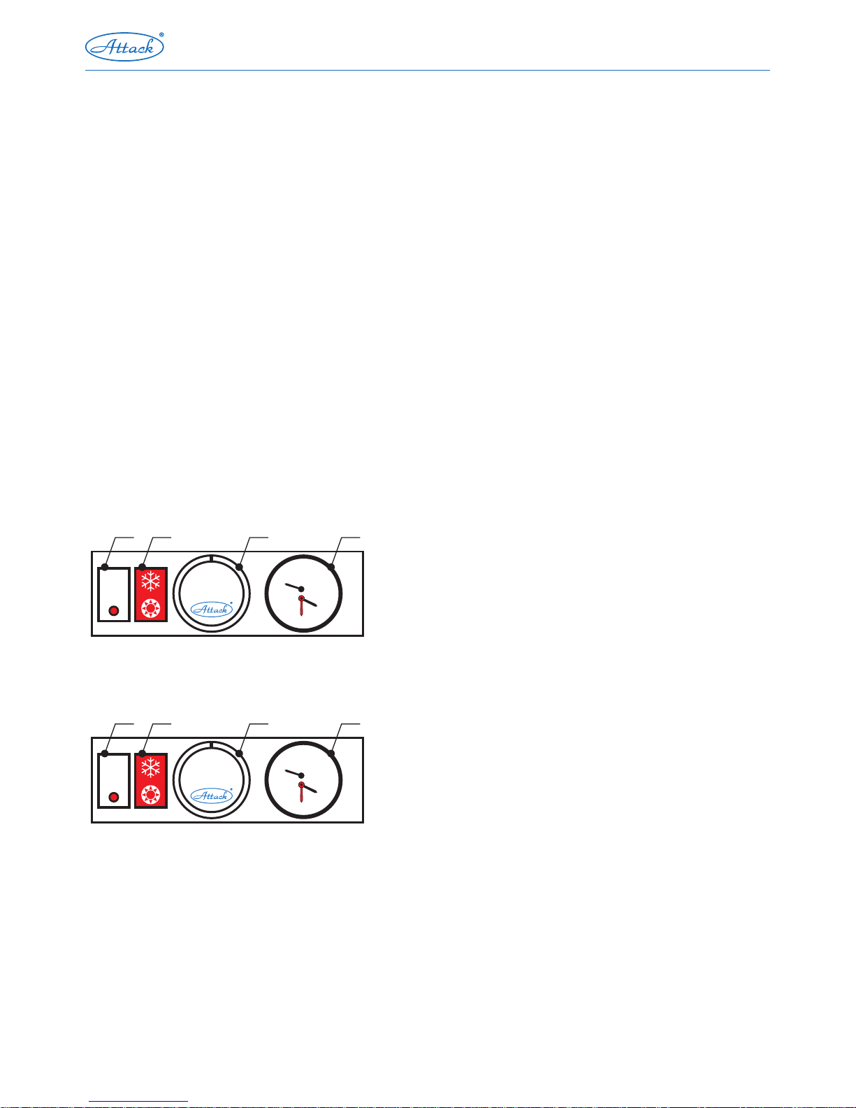
ELECTRICAL FRONT PANEL OF THE EKO, PLQ, KLV, KLQ, E BOILERS
HV – main switch
PR – operation mode switch (only PLQ, KLQ)
KT – boiler thermostat (1–5)
KT – PRODIGY "E" boiler thermostat
ZD – thermomanometer
ELECTRICAL FRONT PANEL OF THE EZ BOILERS
HV – main switch – switch of the tank (EZ)
TD – unblock button (EZ)
KP – adjustable boiler potentiometer
ZD – combined thermomanometer
bar
0
30
60
90
120
0
2
3
4
1
1
5
2
4
3
°C
HV PR KT ZD
bar
0
30
60
90
120
0
2
3
4
1
1
5
2
4
3
°C
HV PR KT ZD
Page 9

| 9
CAST IRON FLOOR STANDING GAS BOILER
EXTERNAL DIMENSIONS OF THE EKO, KLV, PLQ, KLQ, P BOILERS
External boiler dimensions in mm
Boiler type on kW
9 12–20 25–30 35 40–45 50
Width 365 445 535 630 720
Height 845
Depth 580 630 580 610 670
MAIN PARTS OF EKO, KLV, PLQ, KLQ, P BOILERS
1. Electrical installation box
2. Main switch
3. Output switch
4. Boiler thermostat
5. Thermomanometer
6. Emergency thermostat + dish
7. Flue gas thermostat
8. Cast iron body
9. Flow connection of C. H.
10. Return connection of central heating
11. Reverse valve
12. Burners
13. Thermal insulation
14. Condensing dish
15. Draught breaker
16. Plastic board
17. Plate of the plastic board
18. Bottom plastic cover
19. Left side cover
20. Right side cover
21. Upper cover
22. Door
23. Covering plate
24. Rear bottom cover
25. Rear upper cover
26. Stands
V 4600C khol
1
17
6
20
18
22
19
13
21
15
25
24
14
16
9
2 3 4265
8
23
10
11
7
12
I
I
I
I
I
I
I
I
I
I
I
I
I
I
I
I
I
I
I
I
I
I
I
I
I
I
0
20
40
60
80
100
°C
1
2
3
4
5
Depth
A
B
C
Width
30
Height
B
C
290
30
560
185
A
Page 10

10 |
EXTERNAL DIMENSIONS OF E, EZ BOILERS
External boiler dimensions in mm
Boiler type on kW
9 12–20 25–30 35 40–45 50
Width 365 445 535 630 720
Height 845
Depth 580 630 580 610 670
MAIN PARTS OF E, EZ BOILERS
1. Electrical installation box
2. Main switch / Water tank switch
3. Failure unblock
4. Prodigy (E), potentiometer (EZ)
5. Thermomanometer
6. Emergency thermostat
+ sensor
7. Waste gas thermostat
8. Cast iron body
9. Riser pipe of heating
10. Runback pipe of heating
11. Check valve
12. Burners
13. Thermal insulation
14. Condensing dish
15. Draught breaker
16. Plastic board
17. Plate on the plastic board
18. Bottom plastic cover
19. Left side board
20. Right side board
21. Upper plastic cover
22. Door
23. Protective metal sheet
24. Rear bottom sleeve
25. Rear upper cover
26. Stands
I
I
I
I
I
I
I
I
I
I
I
I
I
I
I
I
I
I
I
I
I
I
I
I
I
I
0
20
40
60
80
100
°C
1
2
3
4
5
Depth
A
B
C
Width
30
Height
B
C
290
30
560
185
A
V 4600C khol
1
17
6
20
18
22
19
13
21
15
25
24
14
16
9
2 3 4265
8
23
10
11
7
12
Page 11

| 11
CAST IRON FLOOR STANDING GAS BOILER
CONNECTING THE BOILER TO THE ELECTRICITY MAINS NOT FOR ATTACK P BOILERS
Boilers are plugged into the electrical socket of 230 V/50 Hz placed near the boiler, with a supply
cable ended with a plug. In line with the ČSN EN 60 335-1, the plug must be approachable after the
boiler is installed. The socket must be adequately protected by zeroising or grounding and it must be
connected in line with the ČSN 33 21 80. The boiler and other parts of installation must be grounded.
Installation of the socket, room thermostat, circulation pump and service of electrical boiler parts can
be carried out only by a person with proper electrotechnical qualification, by the law No. 718/2002.
ELECTRICAL EQUIPMENT OF BOILERS
All the electroinstallation is placed on an insulating pad of the electrical board. On the front cover
there is a main switch, output switch (PLQ, KLQ), switch of failure unblocking (E, EZ), control button
of the boiler thermostat and thermomanometer. When the power supply fails, all the euipment
supplied with the power of 230 V is out of operation which means that a valve closes gas flow to
the burners. The flame of ignition burner (EKO, PLQ, P) is still burns and the boiler stays in a standby mode. After the power supply starts again, the function starts automatically. Electrical installation is ready to connect the additional room thermostat, pump and switch contacts of three-way
valve. The room thermostat or the contacts of the three-way valve are connected after removing
the jumper on terminals 7, 8 and the circulation pump is connected to the terminals 3, 4, 5. By the
E boiler type is the room thermostat connected to the terminals 8, 9 and circulation pump to the
terminals 11, 12, 13. By the EZ boiler type is the room thermostat connected to the terminals 6, 7,
three-way valve to the terminals 3, 4, 5 and circulation pump to the terminals 12, 13, 14. Connection
of the room thermostat, circulation pump and three-way valve can be performed only by a person
with electrical qualification by the law No. 718/2002.
START PUTTING THE BOILER INTO OPERATION
1. Remove the door.
2. Plug the flex cable into the electricity mains, the main switch is in the off position.
3. Open the gas supply to the boiler by a manual valve on the inlet pipe.
4. Set the required temperature of outlet water by knob of the thermostat.
5. The temperature is increased by turning the switch to the right (clockwise) and decreased by
turning the switch to the left (anticlockwise).
6. Press the control button of the gas combined electrical valve and hold it for 20 seconds. At the
same time press the button of piezo ignitor hardly for few times. Check the ignition burner
through the hole. ATTENTION – around the check hole there is a risk of burn when touch. Be
careful by work with the valve and piezo ignitor, not to get burned. Release the button of the
valve. The gas flows into the ignition burner and the sensor of thermo-couple is heated by flame.
If the flame is extinguishes, the process of ignition must be repeated (EKO, PLQ, P). By the KLQ,
KLV and EZ versions, are the burners ignited automatically after switching the main switch and
setting up the boiler thermostat.
Page 12

12 |
7. Turn the main switch into the on position. The gas flows into the burner where it is ignited.
8. Close the boiler front door.
Warning: ATTACK P boiler is a version of non-electrical installation.
STOP PUTTING THE BOILER OUT OF OPERATION
For a short-time inactivity:
y switch the main switch off. The valve closes because of losing the voltage and the gas supply is
interrupted
y the flame of ignition burner still burns, the boiler is in a stand-by mode (EKO, PLQ, P)
y in the case of need, put the boiler into operation by switching the main switch on
y ensure the heating system against frost damage
For a long-time inactivity:
y remove the boiler door
y turn the main switch off - the gas supply to the burners gets closed
y turn the control button of the valve in the direction of arrow and release, thus close the gas supply
to the ignition burner and other burners (EKO, PLQ, P)
y unplug the supply cable from electricity mains
y close the manual gas valve on the supply pipe next to the boiler
y close the boiler door
y ensure the heating system against frost damage
Warning: The ATTACK P boiler is without electrical installation.
OPERATION CONTROL
The boiler is secured against dangerous operation states while working. However, it is not possible to prevent from the failures the cause of which is not included in the boiler mechanism. Therefore it is necessary test the boiler once in three days after being started and to check the following:
y whether the system is filled with water and there is no leakage
y whether there is free approach of the outside air
y whether the flue gas or gas cannot be smelled
y whether there is no extra noise when burning the gas and no imperfect burning indicated by the
change of flame's blue color
The breakdowns detected must be reported to the service worker who put the boiler to
operation. If there is a gas leakage, the gas supply must be closed. The breakdowns found
must be removed immediately.
Page 13

| 13
CAST IRON FLOOR STANDING GAS BOILER
FAILURE STATES OF OPERATION
When these occur, the gas supply into the main burner and ignition burner is automatically closed:
y when the thermo-couple (ionisation electrode) is cooled because of: gas supply breakdown,
clogging by dirts, the flame extinguished by condensate, wrong setting of the thermo-couple
with reference to the ignition burner,
y when there is breakdown in the circuit of the boiler thermostat, the water in the boiler body gets
overheated.
The boiler operation cannot be started automatically in such cases. It is not possible to start the
boiler again without the professional service action to remove the problem.
What to do in the case of failure:
No. Failure
Possible cause
Removing Removed by
1. Water leakage from
unsealed areas
a1) released joint
a2) damaged sealing
element
a3) damaged cast iron
a1) tight the joint
a2) replace the element
a3) replace the cast iron
a1) service
a2) service
a3) service
2. Gas discharge from
unsealed areas
a) close the gas supply
b) find the place of leakage
and remove the failure
a) customer
b) service
3. The ignition burner is
not burning properly or
went off after start
a) low gas pressure a1) set up the flame by a
screw
a2) set up the gas pressure
a3) deaerate
a1) service
a2) service
a3) service
4. Boiler has a low output a) low gas pressure
b) unsuitable main jets
a) set up the gas pressure a) service
5. Ignition burner goes off
after igniting repeatedly
a) faulty emergency
thermostat
b) faulty thermocouple
c) faulty gas inlet valve
a) replace the thermostat
b) replace the
thermocouple
c) replace the valve
a) service
b) service
c) service
6. Hot water does not flow
into the heating system
a) same as by 5
b) boiler aerated, low water
pressure
c) faulty reversevalve or
pump
d) damaged thermostat
a) same as by 5
b) deaerate, fill in with
water
c) replace damaged parts
d) replace thermostat
a) same as by 5
b) customer
c) service
d) service
7. Main burners are not
ignited after switching
the thermostat
a) faulty gas valve
b) reset on the flue gas
thermostat activated
a) change the valve
b) check the flue, press
reset on the flue gas
thermostat
a) service
b) service
Page 14

14 |
CHIMNEY DRAUGHT BREAKER
The draught breaker is an important part of the boiler. It is installed on the flue gas exhaust with
stable exhaust from 2 to 200 Pa. This item is removable to enable approach for service works. When
installing back, it is necessary to seal it properly. Dimensions and shape of the draught breaker are
given by the producer and must not be changed!
FUNCTION OF THE DRAUGHT BREAKER:
y safe and perfect burning
y partial elimination of an excessive exhaust, stabilization of the boiler
efficiency
y protection of the boiler against possible influence of reverse draught in the chimney
y reverse draught can start as a result of an incorrectly selected exhaust ventilator in a flat or a
house which is dangerous and not allowed
y in the case of accidental intake of flue gas or outside air intake into the boiler, the draught breaker
ensures accomplished burning for a limited time and flue gas returns from the draught breaker
back to the boiler room
FUNCTION OF THE FLUE GAS THERMOSTAT
The flue gas thermostat serves to interrupt the boiler operation by closing the gas supply into the
boiler, if the reverse flue gas flow occurs. The flue gas thermostat is not switched on automatically
after the sensor cools down. It is necessary to switch it on manually, by the red or black button on
the thermostat. If the boiler operation is blocked again, it is necessary to call service technician. The
flue gas thermostat must not be out of order during the boiler operation. The faulty thermostat
must be replaced only with an original one supplied by producer.
BOILER FUNCTION
The required water temperature is kept by the boiler thermostat. When the water temperature
achieves the adjusted value, the appropriate electrical part of the combined valve is closed.Thereby is the gas supply into the burners stopped.
The thermostat enables the power supply and the main burners are ignited immediately after the water temperature decreases for several degrees under the adjusted value (i.e. starting difference value of thermostat).
The flame control is automatic. If the burning conditions change (big drop of gas pressure, gas
supply broken or burning stopped), the valve closes the gas supply into the burners. The emergency thermostat protects the boiler against overheating, if the boiler thermostat or valve fails.
OUTPUT REGULATION
The boiler is equipped with the basic regulation and control elements that serve for one-level
(EKO, KLV), two-level (PLQ, KLQ) and automatically controlled (E, EZ) output regulation. The regulation of the boiler can be set up and controlled only by a specialized service worker.
Page 15

| 15
CAST IRON FLOOR STANDING GAS BOILER
AFTER SET UP
The most simple regulation is to set up the operation thermostat correctly, depending on the
outside temperature according to the informative values which must be adjusted by the user by
his own experience and various ways of the source dimensioning, heating bodies, construction of
the building, etc.
The boiler works adequately to the selected mode. After reaching the required temperature of
heating water, the flame on burners extinguishes and only the ignition burner burns (EKO, PLQ, P).
After it gets colder, the flame is ignited automatically. With this way of regulation the cycles (on-off)
of the boiler change often, mainly in the transient times of seasons when the heating water temperature is low, and there is excess output. Such operation mode is not good for the boiler and it
increases average consumption of gas. For these times we recommend to decrease the output for
PLQ, KLQ modifications, to prolong the boiler lifetime and to decrease the average gas consumption. By the E, EZ modifications is the output decreased automatically.
REGULATION OF OPERATION
It is possible to use the additional regulation which is not included into the equipment of the
boiler. The installation must be done adequately to the project. It is also possible to use regulators
and room thermostats according to the temperature of the selected reference room or equithermal regulation of the heating water.
There is a wide range of room thermostats of domestic and foreign production from simple ones
up to programmable ones with daily or weekly cycle to regulate the room temperature. In this case
is the temperature of heating water stable and keeps the boiler in longer operating modes. Due this,
the producer recommends to install the mixing circle as a basic element to regulate the operation.
The regulation is done through mixing the hot water from the boiler with returning water in the
heating system. The water of the adequate temperature is prepared by mixing the water from the
boiler with return water and the heated object gets only the necessary amount of heat. Except of the
mixing device there are also the servo-gear and the electronic regulator. The mixing device can be
used separately, without automatic regulation by servo-gear. In this case it must be manually set to
a certain point of scale according to the estimated temperature. A suitable type and size is selected
by project maker as a part of complete additional regulation for automatic operation.
MARKING OF THE BOILER
The marking means the whole identification of the boiler and it is in the form of a adhesive label
placed on the rear cover of the boiler. A brief summary of instructions and information about manipulation is on the label on the internal part of the boiler door.
SPARE PARTS
The producer keeps the particular parts of boilers as spare parts which are provided for guarantee and post-guarantee service only to contract partners on the base of order or claim.
Page 16

16 |
GUARANTEE, CLAIM
The guarantee conditions and instructions for claim are exactly given in the guarantee letter.
Repairs within the guarantee period have to by done by the authorized company.
Attention!
Regarding the conditions of guarantee, the producer does not permit any repairs by an unauthorized organization within the guarantee period.
SERVICE
The authorized company has to check and adjust the boiler every year within the guarantee
period. This check is not included into the guarantee. Even after finishing the guarantee time, the
producer recommends to make any interventions aiming to repairs by a contract service partner.
The actions of the user within the post guarantee time are determined in the part „Maintenance“.
MAINTENANCE
The user is instructed to do only the basic maintenance like removing dirts and dust according to the
cleanliness of environment. The burner parts can be congested by dust and impurities during the boiler
operation. To clean the boiler, it is necessary to undo and clean the burner system by air or by a water
pressure. Only the authorized trained specialist can make the reparations and cleaning of the boiler.
PACKAGING, TRANSPORT, STORING
Boilers are transported in vertical position fixed to a wooden pallet that is removed during the
installation of the boiler. In any case it must not be used as a stand for boiler. To prevent damaging
during manipulation and transport, the boiler is protected by a paper box. The paper box is secured
by a granoflex tape. The boiler must be stored in an un-aggressive space with the temperature of +5
to +50°C and maximum relative humidity of air of 75 %, without any organic steams, gases and dust.
BOILER ACCESSORIES AND DOCUMENTATION
The ATTACK EKO, PLQ, KLQ, KLV, E, EZ, B boilers are delivered completely assembled and functionally tested. The delivery contains the following documentation:
y instruction manual together with a document boiler test certificate on its back side
y guarantee letter
TECHNICAL CHANGES
The producer reserves right for adjustments of the product related to the innovation and technological changes. Such changes do not have to be contained in the instructions.
CONCLUSION
The producer recommends to study all the consumer documentation thoroughly and keep it as a
source of information and instructions regarding to operation of the heating system. Following the
Page 17

| 17
CAST IRON FLOOR STANDING GAS BOILER
advice from the instructions you can use all the advantages of the boiler and avoid various failures
and claims.
You will be awarded by comfortable moments and satisfied with your investment.
Classification of the appliance by STN 070240
Appliance category: I
2
H
Boiler design: B11BS
Connection overpressure of natural gas G20: 20 mbar
SETTING OF THE MODULATION ELECTRONICS OF THE ATTACK EZ BOILER
1. Trimmers
P1 – CH. CAPACITY – setting of the max.
boiler output into the heating system
P2 – ING. CAPACITY – setting of the starting output (10 seconds after ignition)
2. Jumpers
JP1 – natural gas – connected
JP2 – anti-cycling timer
1 – 60 seconds
2 – 120 seconds
3 – 180 seconds
JP3 – connected (should not be
disconnected)
Page 18

18 |
TECHNICAL DATA
ATTACK boiler type Unit 9 12 15 20 25 30 35 40 45 50
Nominal output EKO, KLV, P kW
9 12 15 20 25 30 35 40 45 49,9
Nominal input EKO, KLV, P kW
9,9 13,2 16,5 22 27,5 33 38,5 44 49,5 55
Number of elements pc
2 3 4 5 6 7
Adjustable output PLQ, KLQ kW
5–9 — 12–15 15–20 18–25 24–30 28–35 — 38–45 42–49,9
Modulable output E, EZ kW
5–9 — 10–18 — 16–25 — 25–35 — 30–45 33–49,9
Adjustable input PLQ, KLQ kW
5,5–9,9 — 13,2–16,5 16,5–22 19,8–24,5 26,4–33 30,8–38,5 — 41,8–49,5 46,2–55
Modulable input E, EZ kW
5,5–9,9 — 11–16,5 — 17,6–24,5 — 27,5–38,5 — 33–49,5 36,3–55
Gas pressure in front of the boiler mbar
20
Diameter of nozzles mm
2,5 2,5 2,5 2,7 2,5 2,7 2,7 2,5 2,7 2,5
Pressure to nozzles – EKO, PLQ,
KLV, KLQ, P
kPa
0,8–1,4 0,95 0,7–1,05 0,8–1,2 0,8–1,35 1–1,35 0,7–1,15 1,35 0,85–1,15 0,85–1,25
Pressure to nozzles – E, EZ kPa
0,8–1,4 — 0,5–1,4 — 0,5–1,35 — 0,65–1,15 — 0,6–1,15 0,6–1,25
Fuel consumption by max. output
– EKO, PLQ, KLV, KLQ, P
m3/h
1,06 1,4 1,76 2,35 2,94 3,5 4,12 4,7 5,3 5,85
Fuel consumption by max. output
– E, EZ
m3/h
1,06 — 2,13 — 2,94 — 4,12 — 5,3 5,85
Fuel consumption by min. output
– EKO, PLQ, KLV, KLQ, P
m3/h
0,88 — 1,4 1,76 2,13 2,82 3,3 — 4,4 4,9
Fuel consumption by min. output
– E, EZ
m3/h
0,88 — 1,17 — 1,88 — 2,94 — 3,5 3,8
Fuel Natural gas „G 20“
Natural gas connection DN 15 (Pass through nut 3/4")
Flue exhaust diameter mm 110 135 145 165 180
Volume of the cast iron body l 7 10 13,8 16,8 19,8 22,8
Max. pressure in heating system bar PMS = 4
Connection of heating – forced
circulation / natural circulation (S, P)
G 1" / 6/4"
Boiler weight kg 73 99 125 151 180 208
Power supply V / Hz ~ 230 / 50
Grade of protec tion IP 40
Temperature of the heating
water
°C 40–90 / 0–90 (P)
Efficiency % 90
Flue gas flow g/s 14,4 20,5 28,9 37,2
Electrical input W 15
Page 19

| 19
CAST IRON FLOOR STANDING GAS BOILER
Connecting the electrical installation of the ATTACK EKO boiler
DESCRIPTION:
A – automatics V 4600C
V – main switch
TK – boiler thermostat
TP – room thermostat
OČ – circuit pump
C – capacitor
ST – flue gas thermostat with
reset
TV – three-way valve Honey-
well VC4613
O – orange conductor of the
three-way valve
S – grey conductor of the
three-way valve
TK V
ST
PE
U N U1
U2
N
U2 N U1
A
TP
~ 220 V/50 Hz
C
OČ
12 11
10 9 8 7 6
5
4
3
2 1
TV
S O
F
T P
PP
ČERPADLO
PE
U N U1
U2
N
U2 N U1
A
TP
TK HT V
C
OČ
12 11 10 9 8 7 6
5
4 3
2
1
TV
S O
ST
F
~ 220 V/50 Hz
T P
PP
ČERPADLO
ATTENTION:
Connect the TP (room thermostat), eventually the TV
(three-way valve) as well into
the terminals 7 and 8.
Remove the interconnection!
Connecting the electrical installation of the ATTACK KLV boiler
ATTENTION:
Connect the TP (room thermostat), eventually the TV
(three-way valve) as well into
the terminals 7 and 8.
Remove the interconnection!
DESCRIPTION:
A – automatics VK 4100C
V – main switch
TK – boiler thermostat
TP – room thermostat
OČ – circuit pump
C – capacitor
HT – emergency thermostat
with reset
ST – flue gas thermostat with
reset
TV – three-way valve Honeywell VC4613
O – orange conductor of the
three-way valve
S – grey conductor of the
three-way valve
PUMP
PUMP
Interconnection
Interconnection
Page 20

20 |
Connecting the electrical installation of the ATTACK PLQ boiler
DESCRIPTION:
A – automatics V 4600Q
TP – room thermostat
C – capacitor
A1 – two-stage regulator of
automatics
V – main switch
TK – boiler thermostat
OČ – circuit pump
PR – output switch
ST – flue gas thermostat with
reset
TV – three-way valve Honeywell VC4613
O – orange conductor of the
three-way valve
S – grey conductor of the
three-way valve
Connecting the electrical installation of the ATTACK KLQ boiler
ATTENTION:
Connect the TP (room thermostat), eventually the TV
(three-way valve) as well into
the terminals 7 and 8.
Remove the interconnection!
ATTENTION:
Connect the TP (room thermostat), eventually the TV
(three-way valve) as well into
the terminals 7 and 8.
Remove the interconnection!
DESCRIPTION:
A – automatics V 4100Q
TP – room thermostat
C – capacitor
A1 – two-stage regulator of
automatics
V – main switch
TK – boiler thermostat
OČ – circuit pump
PR – output switch
HT – emergency thermostat
with reset
ST – flue gas thermostat with reset
TV – three-way valve Honeywell VC4613
O – orange conductor of the
three-way valve
S – grey conductor of the
three-way valve
TP
PP
~ 220 V/50 Hz
PE
U N U1
U2
N
U2 N U 1
A
A1
TK
V PR
C
OČ
12 11 10 9 8 7 6
5
4 3
2
1
ST
TV
F
S O
ČERPADLO
T P
PE
U N U1
U2
N
U2 N U1
A
A1
TP
HT TK
V PR
C
OČ
12 11 10 9 8 7 6
5
4 3
2
1
ST
TV
S O
F
~ 220 V/50 Hz
PP
T P
ČERPADLO
PUMP
PUMP
Interconnection
Interconnection
Page 21

| 21
CAST IRON FLOOR STANDING GAS BOILER
1 2
3
4
5
96 7 81110
12
LN
z/ž
1
3
4
2
F1
L
1
2
3
11
7
4
5
6
9
8
10
13
12
L
N
14
15
PE
J4
1
J5
1
J2
1
J3
1
J1
1
R – 10 kΩ
h m m h m h
t
t
r r
h
m
m
h
m h h
č
č
m
m
h
h
m
z/ž
M
h m hhmh
mh
z/ž
h
h
m
h
h
h
č
m
h
z/ž
h
m
h
h
z/ž
h
h
h
h
č
č
h
Connecting the electrical installation of the ATTACK EZ boiler
Connecting the electrical installation of the ATTACK E boiler
ATTENTION:
Connect the TP (room thermostat), eventually the TV
(three-way valve) as well into
the terminals 7 and 8.
Remove the interconnection!
DESCRIPTION:
A – automatics V 4100Q
TP – room thermostat
C – capacitor
A1 – two-stage regulator of
automatics
V – main switch
TK – boiler thermostat PRODIGY
OČ – circuit pump
PR – output switch
HT – emergency thermostat
with reset
ST – flue gas thermostat with reset
TV – three-way valve Honeywell VC4613
O – orange conductor of the
three-way valve
S – grey conductor of the
three-way valve
~ 220 V/50 Hz
PE
U N U1
U2
N
U2 N U 1
A
A1
HT
TK
V
C
OČ
ST
TV
S O
PP
ČERPADLO
T P
12 11
10 9 8 7 6
5
4
3
2 1
TP
Grou nding of
the co ntrolle r
* Note: if the D.H.W. tank is not connected, it is necessary to remove the sensor of the tank
and to replace it with the interconnection!
Thre e-way
valve
Room
ther mostat
Pump Mains s upply
Termin al
Boil er thermo stat
Poten tiomete r
Main s
swit ch
Termin al of the gas v alve’s elec tronic s
Sens or of
heat ing
Conne ctor of
modu lator
Sens or of
the ta nk
summ er / winter
Filte r
Emer gency th ermosta t
with r eset
Flue ga s thermos tat
with r eset
DESCRIPTION:
č – Black
m – Blue
h – Brown
z/ž – Yellow-green
PUMP
Interconnection
Page 22

22 |
NOTES:
Page 23

Stamp, signature of the service organization: ....................................
Obligatory service inspection after the 1st year of operation
Date: .............................
Obligatory service inspection after the 2nd year of operation
Obligatory service inspection after the 3rd year of operation
Stamp, signature of the service organization: ....................................Date: .............................
Stamp, signature of the service organization: ....................................Date: .............................
Data of the customer: (legibly)
Name and surname:
...........................................................................
Street: ................................................................
ZIP code, town: ..................................................
Tel.: ....................................................................
Boiler commissioning certificate
Serial number: ...............................................
Date of commission: ......................................
Service organization:
.......................................................................
Stamp, signature
This page serves for confirming the service inspections and is kept by the customer!
Obligatory service inspection after the 4th year of operation
Stamp, signature of the service organization: ....................................Date: .............................
Page 24

ATTACK, s.r.o. – 01/2016
ATTACK, s.r.o.
Dielenská Kružná 5020
038 61 Vrútky
Slovak republic
Tel: +421 43 4003 103
Fax: +421 43 4003 116
E-mail: export@attack.sk
Web: www.attack.sk
Výrobca ATTACK, s.r.o. si v yhradzuje právo technick ých zmien výrobkov bez predchádzajúceho upozornenia. •ATTACK, s.r.o. producer reserves the right to change technical parameters and dimensions of
boilers without previous warning. •Der Hersteller ATTACK, s.r.o. behält sich das Recht der technischen
Veräderungen an Produkten ohne eine vorige Warnung. •Изготовитель ATTACK, s.r.o. оставляет за
собой право изменения технических параметров и размеров котла без предыдующего предупреждения. •Le producteur ATTACK, s.r.o. réserve le droit des modifications techniques sans l‘avertissement
précédent. •Productor ATTACK, s.r.o. reserva el derecho de cambios técnicos sin adver tencia anterior.
 Loading...