

Page 1
W W W . A T T A C K . S K
WOOD GASIFYING BOILER
ATTACK DPX
STANDARD / PROFI / LAMBDA
USER MANUAL
for correct installation,
operation and cleaning
Important! Read this manual properly before the boiler start-up!
Page 2

Page 3

3
CONTENTS
1. INSTALLATION AND CHIMNEY PARAMETERS................................................................................................. 4
2. VERIFICATION OF THE CORRECT CHIMNEY PARAMETERS ......................................................................... 5
3. DEVICES FOR CHIMNEY DRAUGHT MEASURING ........................................................................................... 6
4. OPERATION PRESSURE IN HYDRAULIC CIRCUIT ............................................................................................ 7
5. BOILER PROTECTION AGAINST EXCESSIVE CONDENSATION – ATTACK-OVENTROP ........................ 7
6. CORRECT ASHTRAYS POSITION ........................................................................................................................... 8
7. FUEL .............................................................................................................................................................................. 8
8. AFTERCOOLING CIRCUIT INSTALLATION ......................................................................................................... 9
9. CORRECT ADJUSTMENT OF AIR INLETS ............................................................................................................ 9
10. ASHTRAY CLEANING .......................................................................................................................................... 10
11. HOW TO CLEAN SPACE AROUND THE ASHTRAY ..................................................................................... 12
12. EXCHANGER PIPES CLEANING BY LEVER OF TURBULATORS ............................................................... 13
13. HOW TO CLEAN SPACE UNDER EXCHANGER ........................................................................................... 14
14. POSITION OF LEVER OF TURBULATORS BY CLEANING .......................................................................... 15
15. TOOLS FOR CLEANING OF SPACE UNDER EXCHANGER ........................................................................ 16
16. CONTROL OF TUBULAR EXCHANGER´S FUNCTIONALITY ..................................................................... 17
17. ACCESS TO TUBULAR EXCHANGER .............................................................................................................. 17
18. EXCHANGER´S COVER REMOVAL .................................................................................................................. 18
19. CONTROL OF CORRECT FUNCTION OF THE HEAT-UP FLAP ................................................................. 18
20. TURBULATOR THREADS CLEANING.............................................................................................................. 19
21. CLEANING OF THE VENTILATOR´S OPERATION AREA ............................................................................ 20
22. CLEANING OF RADIAL IMPELLER’S VANES ................................................................................................. 21
23 SUMMARY OVERVIEW OF REGULAR CLEANING OF PARTICULAR BOILER PARTS .......................... 22
24. OVERVIEW OF VENTILATORS USED IN PARTICULAR BOILERS ............................................................. 22
Page 4
4
1. INSTALLATION AND CHIMNEY PARAMETERS
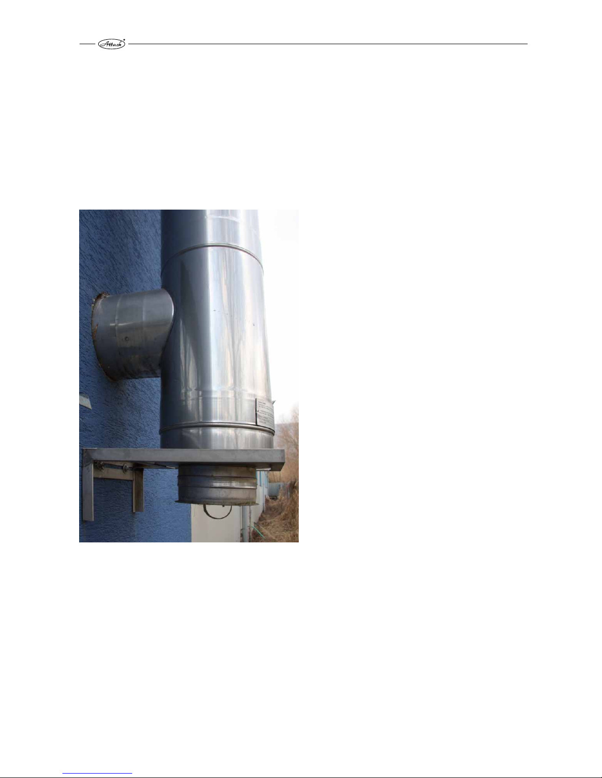
By installation of chimney connection to boiler it is necessary to care about correct outlet of flue
gas and eventual condensate, not to let it fall back into the boiler. For this purpose you can use
the T-piece, see picture below. Exhaust connection comes into the chimney vent. If it is not
possible to connect boiler to chimney vent directly, then the adequate extension of exhaust
connection has to be as short as possible, and no longer than 1 m, without additional heating
surface and it has to go up in direction to the chimney. Exhaust connections must not go
through foreign dwelling or utility units. Internal cross-section of the exhaust connection must
not taper in direction to the chimney. Try to minimize usage of elbows by installation. Chimney
has to be constructed in conformity with the norms STN 73 4201 and STN 73 4210.
Prescribed values of the correct height and
cross-section chimney dimensions:
DPX15, DPX25, DPX35, DPX45
20×20 cm min height 7 m
20 cm min. height 8 m
15×15 cm min height 11 m
16 cm min height 12 m
Page 5

5
2. VERIFICATION OF THE CORRECT CHIMNEY PARAMETERS
Correct boiler function significantly depends on quality chimney with correct parameters.
Minimum chimney diameter is 150 mm, however, 200 mm is recommended. Chimney has to be
designed or regulated to achieve prescribed draught of 23–30 Pa at nominal boiler flue gas
temperature value.
ATTENTION! Chimney which does not fulfil required parameters may cause limited
boiler function (Low flue gas temperature, low output, excessive condensation of
tubular exchanger, shorter life-time, even total boiler disfunction)! Guarantee does
not relate to the boiler installed with the chimney of incorrect parameters.
Page 6

6
3. DEVICES FOR CHIMNEY DRAUGHT MEASURING
It is possible to check correct chimney draught by some types of analysers or by exact
differential pressure-gauge. On the picture there is draught reducer too, also useful for correct
draught setting.
Page 7

7
4. OPERATION PRESSURE IN HYDRAULIC CIRCUIT
Operation pressure must not exceed limit of 2,5 bar.
ATTENTION! Expanse vessel and safety valve must be installed in the system.
5. BOILER PROTECTION AGAINST EXCESSIVE
CONDENSATION – ATTACK-OVENTROP
For correct boiler function and its long life-time it is necessary to keep return water temperature
always higher than 65 °C. Set boiler thermostat to 80-85 °C, which is ideal boiler operation
temperature. Boiler guarantee is valid only in case that the ATTACK-OVENTROP device was
installed into the hydraulic system.
ATTENTION! If the ATTACK OVENTROP device is not installed, it may cause shorter
boiler life-time.
Page 8
8
6. CORRECT ASHTRAYS POSITION
Ashtray position is important for correct boiler operation. It is not necessary to take out the
ashtray while cleaning, but it is important to check its correct position sometimes. Ashtray has to
be completely shifted rearwards.
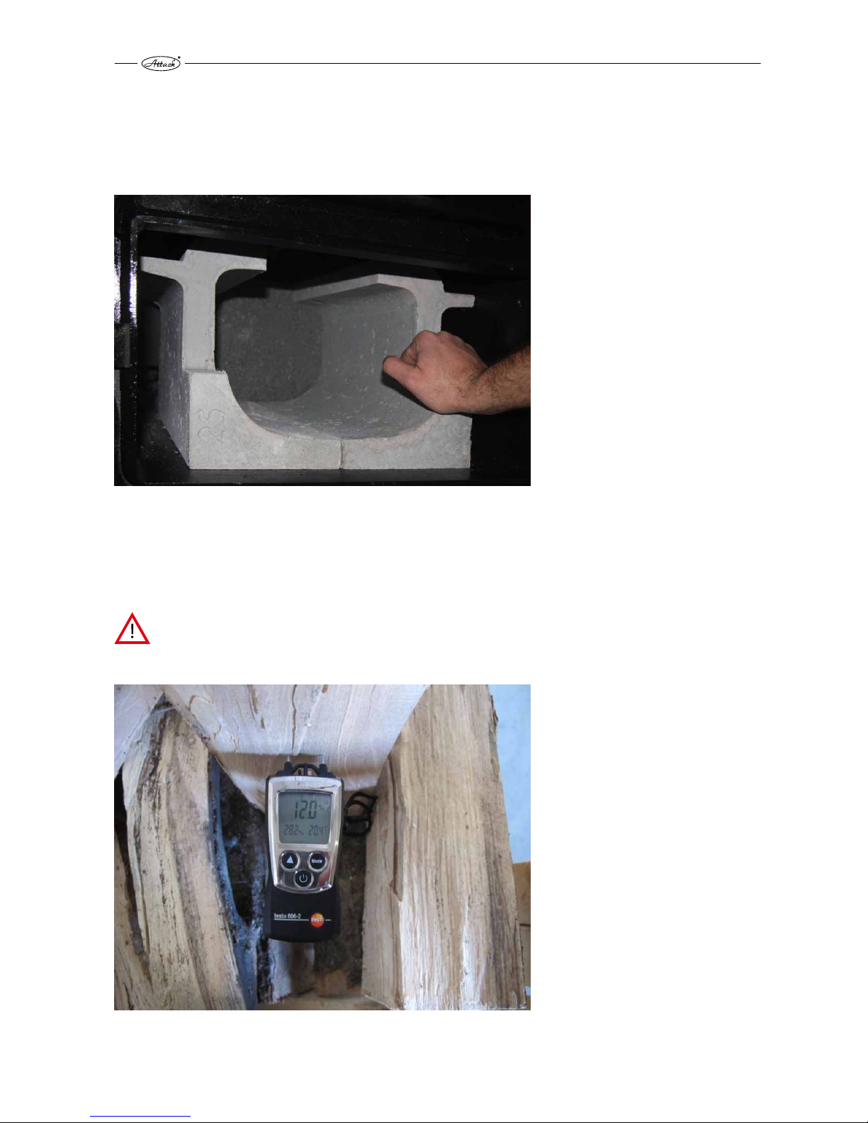
7. FUEL
Use suitable fuel for wood gasifying boiler operation – soft or hard wood logs. Wood moisture
has to be in range of 12–20 % (related to time of min. 15 month of free storing at the fresh air).
Alternatively it is possible to use wood briquets of cylindrical shape with opening in the middle.
ATTENTION! Wood with moisture exceeding 20 % shortens boiler life-time, causes
lower output, excessive condensation in tubular boiler exchanger, which may
require additional out-of-warranty service!
Page 9

9
8. AFTERCOOLING CIRCUIT INSTALLATION
Boiler warranty is valid only in case, that functional thermostatic valve, connected to the cold
water source, is installed in the boiler aftercooling circuit. If the cold water source depends on
electricity (home water plant), whole device can be out of order in case of power failure. In this
cases, use water tanks placed higher than boiler, connected to thermostatic valve. Tank volume
has to be appropriate to the boiler outuput.
ATTENTION! If there is no aftercooling circuit on the boiler and it comes to boiler
overheating, serious and non-recurring damage or even fire may occure.
9. CORRECT ADJUSTMENT OF AIR INLETS
Correct adjustment of primary and secondary air by STANDARD and PROFI boilers is marked on
tin-plate and it is not necessary to manipulate with that. Correct setting of primary air (upper
butterfly) is 100 %, secondary air (bottom butterfly) is set to 35 %. This relates to all outputs of
DPX boilers (15, 25, 35, 45).
Page 10

10
10. ASHTRAY CLEANING
Internal space of ashtray has to be cleaned from accumulated ash at least 1× a day. Cleaning
with scoop is very effective and easy. Cleaning can be done very easily and fast also by full boiler
operation.
ATTENTION! Hot ash from ashtray can still smoulder, therefore it is not supposed to
be put into trash bin, however into appropriate tin-plate bin, not to cause the fire.
Page 11

11
Page 12

12
11. HOW TO CLEAN SPACE AROUND THE ASHTRAY
Space around the ashtray has to be cleaned regularly, at least 1× a week. Use suitable tool, fire
hook delivered with boiler is ideal for this purpose. It is not necessary to take out the refractory
pieces from the boiler´s ashtray.
ATTENTION! Unsufficiently cleaned space around ashtray may cause limited boiler
function.
Page 13

13
12. EXCHANGER PIPES CLEANING BY LEVER OF
TURBULATORS
It is necessary to move lever of turbulators cleaning regularly, preferably by every boiler loading,
at least 3 times a day. It is necessary to move it by full lever uplift, 5–6 times upwards and
downwards.
ATTENTION! If it is not moved with the lever regularly, exchanger pipes may clog
and therefore cause turbulators blockage, lower efficiency, decreased output and
incorrect boiler function. In this case is boiler warranty not valid. If you cannot
move the lever of turbulators, stop the boiler and call specialized service.
Page 14

14
13. HOW TO CLEAN SPACE UNDER EXCHANGER
It is necessary to clean space under exchanger pipes in regular intervals. This interval depends
on boiler operation time, but it has to be done at least 1× a week. Remove cover of the opening
for cleaning carefully, not to damage the sealing. After cleaning of space under exchanger,
install the cover – it has to be sufficiently screwed and air-proof.
ATTENTION! Otherwise there may come to insufficient air circulation in the boiler
and thereby to incorrect boiler function (ineffective combustion, decreased output,
low flue gas temperature, etc.).
Page 15

15
14. POSITION OF LEVER OF TURBULATORS BY CLEANING
To clean space under exchanger of the DPX 15, 25, 35 boilers, it is necessary to lift lever of
turbulators fully up, turbulators go into the pipes and thereby there is free space for cleaning. By
the DPX 45 boiler it is ideal to lift the lever into middle position.
Page 16

16
15. TOOLS FOR CLEANING OF SPACE UNDER EXCHANGER
To clean space under exchanger it is possible to use fire hook delivered with the boiler.
Page 17

17
16. CONTROL OF TUBULAR EXCHANGER´S FUNCTIONALITY
Check regularly correct functionality of tubular exchanger – at least 1× a month. Firstly, remove
rear upper cover.
17. ACCESS TO TUBULAR EXCHANGER
Release wing matrices.
Page 18

18
18. EXCHANGER´S COVER REMOVAL
Check correct functionality fo turbulators, while the boiler is out of order. Remove the cover to
get to the tubular exchanger.
ATTENTION! Cover must be sufficiently tighten and air-proof. Otherwise it may
cause incorrect boiler function
19. CONTROL OF CORRECT FUNCTION OF THE HEAT-UP FLAP
For correct function of the heat-up flap it is necessary to check and clean bearing surfaces
regularly.
Page 19

19
20. TURBULATOR THREADS CLEANING
If the boiler was from any reason
operated in incorrect way, it is
possible, that the turbulators were
clogged and thereby the flue gas
transition was decreased. In this case
it is necessary to demount
turbulators and to clean the space
between particular threads, for
example by wire brush. Put the
turbulators back into the pipes, not
to decrease efficiency of the boiler.
(This is not related to the 15 DPX
model).
Page 20

20
21. CLEANING OF THE VENTILATOR´S OPERATION AREA
Operation space of the ventilator´s radial impeller has to be cleaned at least 1× a year. To do so,
release matrices of the ventilator´s flange and demount ventilator. Clean the operation area
from soot and mud. By demounting, take care to tighten matriaces of the ventilator´s flange
sufficiently.
ATTENTION! Demount ventilator, while boiler is out of order. Insufficiently cleaned
ventilator´s operation area may cause its limited function.
Page 21

21
22. CLEANING OF RADIAL IMPELLER’S VANES
Vanes of ventilator have to be cleaned from dirt at least 1× a year by suitable tool (wire brush).
ATTENTION! Too dirty vanes of ventilator decrease its efficiency and thereby cause
limited boiler function.
Page 22

22
23 SUMMARY OVERVIEW OF REGULAR CLEANING OF
PARTICULAR BOILER PARTS
Cleaning* Point Daily Weekly Annually
Ash removing 10 1×
Space around ash tray 11 1×
Space under exchanger 15 1×
Lever of turbulators 12 5–6×
Flap 19 1×
Space of ventilator 21 1×
Radial impeller of ventilator 22 1×
* Minimal recommended cleaning intervals. According to intensity of heating they can be also
shorter.
24. OVERVIEW OF VENTILATORS USED IN PARTICULAR
BOILERS
Ventila
tor
Boiler type FCJ4C52S FCJ4C82S R2E180-CG82-01
DPX
15 •
25 •
30 •
35 •
40 •
45 •
DP
15 •
25 •
35 •
45 •
75 •
95 ••
Page 23

Page 24

ATTACK, s.r.o. – 01/2015
ATTACK, s.r.o.
Dielenská Kružná 5020
038 61 Vrútky
Slovakia
Tel: +421 43 4003 103
Fax: +421 43 4003 116
E-mail: export@attack.sk
Web: www.attack.sk
Výrobca ATTACK, s.r.o. si vyhradzuje právo technických zmien výrobkov bez predchádzajúceho
upozornenia. • ATTACK, s.r.o. producer reserves the right to change technical parameters and dimensions
of boilers without previous warning. •Der Hersteller AT TACK, s.r.o. behält sich das Recht der technischen
Veräderungen an Produkten ohne eine vorige Warnung. • Изготовитель AT TACK, s.r.o. оставляет за собой
право изменения технических параметров и размеров котла без предыдующего предупреждения.
• Le producteur ATTACK, s.r.o. réserve le droit des modifications techniques sans l‘aver tissement
précédent. • Productor ATTACK, s.r.o. reserva el derecho de cambios técnicos sin advertencia anterior.
 Loading...