

Page 1

W W W . A T T A C K . S K
WOOD GASIFYING BOILER
ATTACK DPX
STANDARD / PROFI / LAMBDA
INSTRUCTIONS FOR USE
Page 2

2
CONTENTS
ATTACK DPX – THE WOOD GASIFYING BOILER .......................................................................... 4
1INTRODUCTION ..................................................................................................................... 6
1.1GENERAL DESCRIPTION ............................................................................................................................ 6
1.2MARKING OF THE BOILERS ATTACK DPX ............................................................................................ 6
1.3TECHNICAL PARAMETERS ........................................................................................................................ 7
1.4DIMENSIONS OF THE BOILERS ATTACK DPX ..................................................................................... 8
1.5CONTROL PANEL ......................................................................................................................................... 9
1.5.1ATTACK DPX STANDARD ................................................................................................................. 9
1.5.2ATTACK DPX LAMBDA ................................................................................................................... 10
1.6PURPOSE OF USE ..................................................................................................................................... 11
1.7TECHNICAL DESCRIPTION ..................................................................................................................... 11
2TECHNICAL DESCRIPTION OF THE ATTACK DPX STANDARD .......................................... 12
2.1OPERATING PRESCRIPTIONS ................................................................................................................ 12
3TECHNICAL DESCRIPTION OF THE ATTACK DPX PROFI .................................................... 14
3.1ADVANTAGES OF THE REGULATOR ................................................................................................... 14
3.2BASIC DESCRIPTION OF THE REGULATOR ....................................................................................... 15
3.3CONNECTION OF THE REGULATOR BY HYDRAULIC SCHEMES................................................. 16
3.3.1WOOD GASIFYING BOILER + HEATING CIRCUIT ................................................................... 16
3.3.2WOOD GASIFYING BOILER + HEATING CIRCUIT + WARMING OF D.H.W. ..................... 17
3.3.3WOOD GASIFYING BOILER + HEATING CIRCUIT + WARMING OF ACCUMULATION
TANK ............................................................................................................................................................... 18
3.3.4WOOD GASIFYING BOILER + HEATING CIRCUIT + WARMING OF ACCUMULATION
TANKS CONNECTED IN SERIE ........................................................................................................................ 19
3.3.5WOOD GASIFYING BOILER + HEATING CIRCUIT + WARMING OF THE COMBINED
ACCUMULATION TANK ................................................................................................................................... 20
3.4REGULATOR CONTROL AND OPERATING MODES ........................................................................ 21
3.5SETTING THE USER PARAMETERS ....................................................................................................... 22
3.6SETTING THE SERVICE PARAMETERS ................................................................................................. 23
3.7DESCRIPTION OF PARAMETERS .......................................................................................................... 24
3.8TESTING THE REGULATOR OUTPUTS ................................................................................................ 26
3.9RESET OF THE REGULATOR´S PRODUCTION SETTINGS .............................................................. 27
3.10EXIT FROM SERVICE MENU ................................................................................................................... 27
3.11ERROR MESSAGES .................................................................................................................................... 27
3.12DISASSEMBLY OF THE REGULATOR ................................................................................................... 28
3.13TECHNICAL SPECIFICATION OF THE REGULATOR ......................................................................... 28
4TECHNICAL DESCRIPTION OF THE ATTACK DPX LAMBDA ............................................... 29
4.1REGULATION OF BURNING ................................................................................................................... 29
4.2IGNITING AND REFILLING THE FUEL .................................................................................................. 29
4.3IGNITING OR REFILLING THE FUEL ..................................................................................................... 29
4.4REFILLING THE FUEL DURING THE BOILER OPERATION .............................................................. 29
4.5FUNCTION AND DISPLAYING THE TEXT BY IGNITING OR REFILLING THE FUEL .................. 30
4.6DISPLAY OF THE OPERATING MODE BY THE BOILER STARTED ................................................ 30
4.7EXCESSIVE FLUE GAS TEMPERATURE ................................................................................................ 31
4.8BOILER OVERHEATING ........................................................................................................................... 31
4.9DISPLAY OF THE OPERATING MODE WHEN THE BOILER IS OUT OF ORDER ........................ 31
4.10FUNCTIONS OF THE AUTOMATIC PROTECTION ............................................................................ 31
4.11INFORMATION ABOUT THE CURRENT OPERATION ...................................................................... 31
Page 3

3
4.12INFORMATION DISPLAYED: .................................................................................................................. 32
4.13SETTING FOR COMMISSION OF THE ATTACK DPX LAMBDA ..................................................... 33
4.14CANCELLATION OF THE PRODUCER´S FUNCTION ........................................................................ 35
4.15SAFETY TEST .............................................................................................................................................. 37
4.16MAINTENANCE OF THE HEATING SYSTEM AND THE BOILER .................................................... 38
4.17BOILER CLEANING .................................................................................................................................... 40
4.18PRESCRIBED FUEL .................................................................................................................................... 40
4.19ASSEMBLY AND INSTALLATION OF THE BOILER ........................................................................... 41
4.20BOILER PROTECTION AGAINST CORROSION .................................................................................. 43
4.21BINDING NORMS FOR PROJECTING AND INSTALLATION OF THE BOILERS ......................... 44
4.22INSTALLATION AND REPLACEMENT OF THE FIREPROOF PARTS ............................................. 45
4.23BOILER CONNECTION ............................................................................................................................. 46
4.24OPERATION WITH ACCUMULATION TANKS.................................................................................... 46
4.25BOILER PROTECTION AGAINST OVERHEATING .............................................................................. 47
4.26TRANSPORT, HANDLING AND STORING .......................................................................................... 47
4.27INSTRUCTIONS FOR PRODUCT DISPOSAL AFTER TERMINATION OF ITS SERVICE LIFE..... 47
4.28DISPOSAL OF THE PACKAGING ........................................................................................................... 47
4.29ACCESSORIES ............................................................................................................................................ 47
4.30POSSIBLE ERRORS AND SOLUTIONS .................................................................................................. 48
4.31FAULTS AND ERRORS WITH THE SYSTEM ATTACK DPX LAMBDA ........................................... 49
4.32CHARACTERISTICS OF THE WATER TEMPERATURE SENSOR (THE PROFI VERSION) .......... 52
4.33ELECTRICAL SCHEMES OF CONNECTION OF THE BOILERS ATTACK DPX STANDARD,
LAMBDA ................................................................................................................................................................... 53
4.34ATTACK DPX PROFI ................................................................................................................................. 54
4.35ATTACK DPX LAMBDA ............................................................................................................................ 55
4.36THE ORIGINAL ES DECLARATION OF CONFORMITY NR. POZ-015/260713 ........................... 58
Page 4

4
ATTACK DPX – THE WOOD GASIFYING BOILER
Installation, heat-up test and user training must be performed by the technician trained by
producer. The technician must fill the protocol about the installation of the boiler.
By gasification of wood it comes to creation of tar and condensates (acids) in the fuel tank.
Due to this there must be a mixing device installed behind the boiler to keep the minimum
temperature of return water at 65 °C. The temperature of water in the boiler during its
operation must be within the range of 80 – 90 °C.
The boiler must not be permanently operated within the output lower than 50 %.
If the circuit pump is being used, its operation must be controlled by a separate thermostat
to ensure the prescribed minimum temperature of the return water.
Ecological boiler operation is related to its nominal output.
It is recommended to install the boiler together with the accumulation tank and mixing
device. This ensures the fuel saving of 20–30% and longer lifetime of the boiler and chimney.
If it is not possible to connect the boiler to the accumulation tank, it should be connected
with at least one equalization tank with the volume of approximately 25 l / 1 kW of the
boiler´s output.
By the operation with lower output (summer operation and D.H.W. preparation) it is
necessary to heat the boiler up every day.
Only the dry fuel of 12–20 % moisture can be used (by the higher moisture of fuel is the
boiler output decreased and its consumption increased).
The DPX boiler liner is equipped with the tubular exchanger, except of the 15 DPX boiler.
Tubes in the exchanger of the 15 DPX are cleaned by an appropriate kit delivered together
with the boiler.
Due to the economical operation and correct functionality it necessary to choose an
appropriate boiler output. The nominal output of the boiler has to be adequate to the
temperature loss of the heated object.
The boiler must be used only for the purpose that it is intended for and only in the way
given in this manual.
CAUTION – After disconnecting the boiler from electricity mains there is still fuel
burning. Do not open the boiler door until the temperature decreases below 40 °C.
The warranty for the boiler is not valid:
if it is not operated with the prescribed fuel – i.e. wood with the moisture lower than 20 %
if no mixing device Regumat ATTACK-OVENTROP is installed in the system to ensure the
return water temperature of at least 65 °C during the boiler operation
Page 5

5
if no functional thermostatic valve is installed on the aftercooling circuit (WATTS STS20) of
the boiler, connected to the cold water inlet.
This device is not supposed to be used by persons (including children) with physical, sensual or
mental disability or insufficient experience due to which they are not able to use the device in a
safe way without being supervised or instructed about the boiler operation by the person
responsible for their safety. Do not to allow the children to play with the device.
If the power supply cable is damaged, it must be replaced with a special cable available by
producer or by a service technician!
Be careful by work with device! The Lambda sensor works by high temperatures (300 °C)
and there is a danger of getting burnt if you are not careful enough!
The warning sign
This warning sign appears in the manual when the health or property is threatened, in case that
the instructions are not exactly kept.
Two types of the warning signs and symbols are used in this manual:
WARNING – Information about the potentially dangerous situation that could cause
serious threat to health or property if advised actions are not taken.
CAUTION – Warns about the less safe way of work and procedures that may cause health
injury of material damage.
Page 6

6
1 INTRODUCTION
Dear customer,
thank you for your trust and purchase of our product – the ATTACK wood gasifying boiler. We wish it
serves you reliably for a long time. The reliable and correct function of device is related to its
operation and therefore it is necessary to read this user manual. The manual is written with respect to
the correct function of the boiler.
The correct function of the boiler particularly depends on the following:
choice of the correct boiler output and type
perfect commissioning
reasonable operation
regular professional maintenance
reliable service
1.1 GENERAL DESCRIPTION
Wood gasifying boiler ATTACK DPX
Name: WOOD GASIFYING BOILER ATTACK DPX 15, 25, 30, 35, 40, 45,
IN VERSION „STANDARD“, „PROFI“, „LAMBDA“
Type: ATTACK DPX 15, 25, 30, 35, 40, 45
Max. operating pressure: 250 kPa
Volume of water: 80, 100, 110, 128 l
El. power supply: 230 V/50 Hz/10 A
E. input: 78 W
Fuel: Dry wood with heat value of 15–17 MJ/kg, moisture of 12–20 %,
diameter of 80–150 mm
Nominal output: 15, 25, 30, 35, 40, 45 kW
The wood gasifying boiler ATTACK DPX is intended for economical and ecological heating of
family houses, cottages, small plants and similar objects.
1.2 MARKING OF THE BOILERS ATTACK DPX
ATTACK DPX 15 STANDARD
25 PROFI
30 LAMBDA
35
40
45
Wood gasifying boiler
Boiler output
Version
Page 7
7
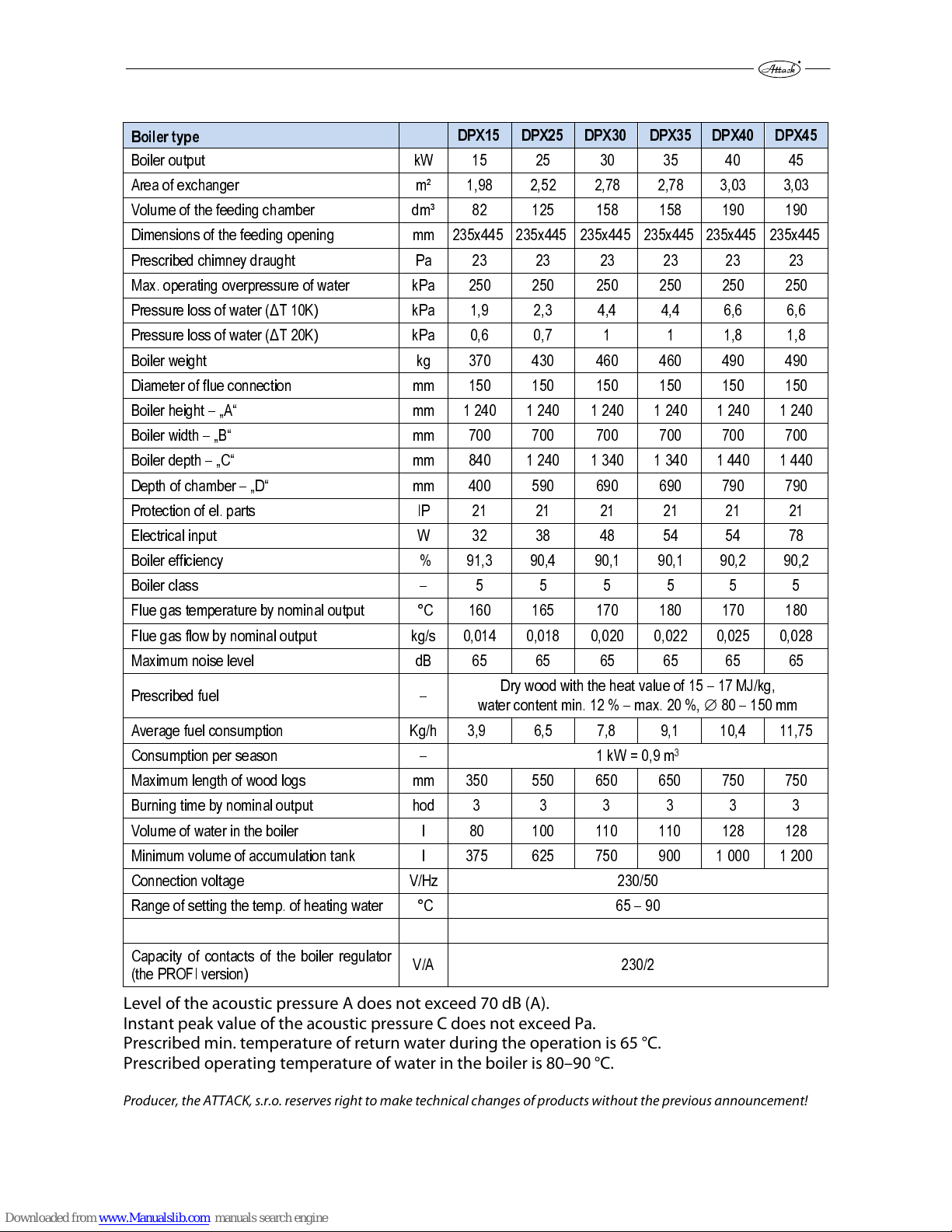
1.3 TECHNICAL PARAMETERS
Boiler type
DPX15 DPX25 DPX30 DPX35 DPX40 DPX45
Boiler output kW 15 25 30 35 40 45
Area of exchanger m² 1,98 2,52 2,78 2,78 3,03 3,03
Volume of the feeding chamber dm³ 82 125 158 158 190 190
Dimensions of the feeding opening mm 235x445 235x445 235x445 235x445 235x445 235x445
Prescribed chimney draught Pa 23 23 23 23 23 23
Max. operating overpressure of water kPa 250 250 250 250 250 250
Pressure loss of water (ΔT 10K) kPa 1,9 2,3 4,4 4,4 6,6 6,6
Pressure loss of water (ΔT 20K) kPa 0,6 0,7 1 1 1,8 1,8
Boiler weight kg 370 430 460 460 490 490
Diameter of flue connection mm 150 150 150 150 150 150
Boiler height – „A“ mm 1 240 1 240 1 240 1 240 1 240 1 240
Boiler width – „B“ mm 700 700 700 700 700 700
Boiler depth – „C“ mm 840 1 240 1 340 1 340 1 440 1 440
Depth of chamber – „D“ mm 400 590 690 690 790 790
Protection of el. parts IP 21 21 21 21 21 21
Electrical input W 32 38 48 54 54 78
Boiler efficiency % 91,3 90,4 90,1 90,1 90,2 90,2
Boiler class – 5 5 5 5 5 5
Flue gas temperature by nominal output °C 160 165 170 180 170 180
Flue gas flow by nominal output kg/s 0,014 0,018 0,020 0,022 0,025 0,028
Maximum noise level dB 65 65 65 65 65 65
Prescribed fuel –
Dry wood with the heat value of 15 – 17 MJ/kg,
water content min. 12 % – max. 20 %,
80 – 150 mm
Average fuel consumption Kg/h 3,9 6,5 7,8 9,1 10,4 11,75
Consumption per season – 1 kW = 0,9 m3
Maximum length of wood logs mm 350 550 650 650 750 750
Burning time by nominal output hod 3 3 3 3 3 3
Volume of water in the boiler l 80 100 110 110 128 128
Minimum volume of accumulation tank l 375 625 750 900 1 000 1 200
Connection voltage V/Hz 230/50
Range of setting the temp. of heating water °C 65 – 90
Capacity of contacts of the boiler regulator
(the PROFI version)
V/A 230/2
Level of the acoustic pressure A does not exceed 70 dB (A).
Instant peak value of the acoustic pressure C does not exceed Pa.
Prescribed min. temperature of return water during the operation is 65 °C.
Prescribed operating temperature of water in the boiler is 80–90 °C.
Producer, the ATTACK, s.r.o. reserves right to make technical changes of products without the previous announcement!
Page 8

8
1.4 DIMENSIONS OF THE BOILERS ATTACK DPX
DPX15 DPX25 DPX30 DPX35 DPX40 DPX45
Flow connection – „E“ G 6/4" G 6/4" G 6/4" G 6/4" G 2" G 2"
Return connection – „F“ G 6/4" G 6/4" G 6/4" G 6/4" G 2" G 2"
KEY:
1. Boiler body 5. Suction fan 9. Control panel 13.Flow connection
2. Upper cover 6. Chimney 10. Drain valve 14. Return connection
3. Feeding door 7. Flap of primary air 11. Cooling circuit 15. Pull rod of the chimney flap
4. Ash tray door 8. Flap of secondary air 12. Lid of the cleaning opening 16. Lever for exchanger cleaning
Page 9

9
1.5 CONTROL PANEL
1.5.1 ATTACK DPX STANDARD
The wood gasifying boiler "ATTACK DPX STANDARD" is controlled by the boiler and the flue gas
thermostat.
1 – Safety thermostat
with reset
2 – Fuse
3 – Main switch
4 – Flue gas thermostat
5 – Boiler thermostat
6 – Thermo-manometer
Description:
1. Safety thermostat with reset – boiler protection against overheating (after exceeding the
temperature of 110 °C is the boiler disconnected from electricity mains). After the
temperature decreases below 85 °C, it is necessary to undo the reset cover and to press the
restart button manually.
2. Fuse – boiler protection against short circuit
3. Main switch – boiler start and stop for the case of need
4. Flue gas thermostat – the fan is stopped after the flue gas temperature decreases below
the adjusted value
ATTENTION! Set this thermostat to 0 °C by heating up. After the fuel starts to burn, set the
flue gas thermostat to the „Operation“ position. When the temperature decreases under
the adjusted value, the exhaust fan is stopped. To start the fan again, set the lower
temperature value on the thermostat. The optimal setting for operation will be found by
experience.
5. Boiler thermostat – serves to set the max. temperature of water in the boiler (After
exceeding the adjusted temperature is the fan stopped and the boiler works at min.
output. After the temperature decreases below the adjusted value, the fan is started again
and the boiler works at max. output).
6. Thermo-manometer – shows the output temperature of water from the boiler and the
operating pressure
Pull rod of the chimney flap – serves to close and to open the heat up flap (always by opening
the feeding door)
Lever for exchanger cleaning – serves to clean the holes of the exchanger
Page 10
10
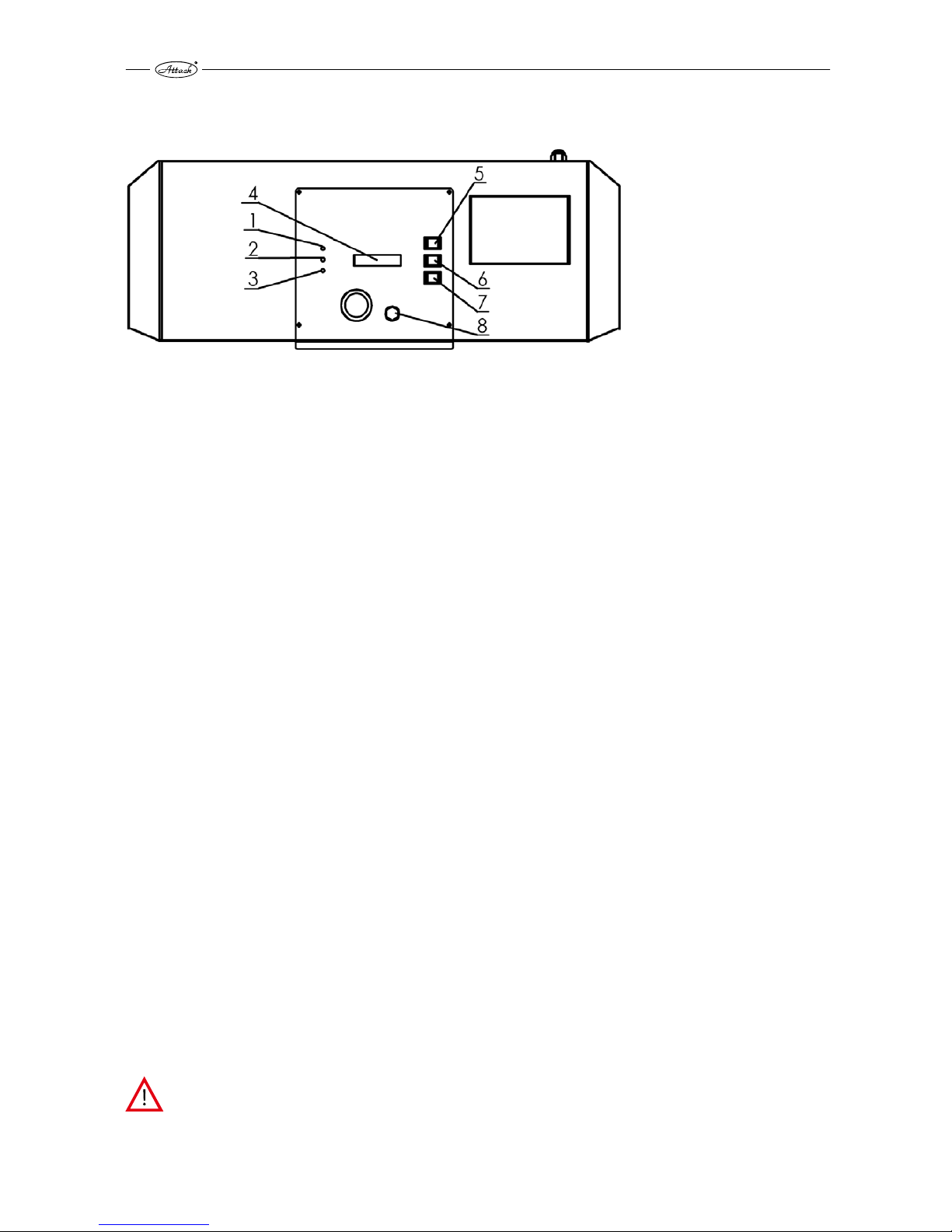
1.5.2 ATTACK DPX LAMBDA
Key:
1. – Green indicator light
2. – Yellow indicator light
3. – Red indicator light
4. – Display
5. – Button „+“
6. – Button „–„
7. – Button „←“
8. – Reset of the safety
thermostat
Indicator light 1: Lights, when the boiler was started by the button „+“ (5)
automatically stops after the fuel burns down or when the boiler was manually
stopped by the button „–“ (6).
Indicator light 2: Lights in case of the following faults:
o incorrectly measured values of the flue gas temperature
o see the chapters Errors and alarms
Indicator light 3: Lights or flickers in the case of error or alarm:
o STB started – Reset (error, message (3) displayed)
o incorrectly measured values of the boiler temperature (error, message (3) displayed)
o too high flue gas temperature (alarm, message (3) displayed)
o overheating – do not open! (boiler temperature over 90 °C, display 3 flickers )
o see the chapter Errors and alarms
Display 4: Displays the operating data for different settings by errors. If the boiler is stopped
and no fault is displayed, the display illumination is turned off after 15 minutes.
Button 5 (+): The display illumination is turned on after pressing the button for the first time.
The boiler is started after the button is pressed again – then it is possible to heat it
up or to refill the fuel. Also other settings can be done by this button (see the
Button 7 below).
Button 6 (–): Serves to stop the boiler. This function is used only for an emergency stop, e.g. if
there is no water in the heating system or is the sensor for overheating is not
working. Also other settings can be done by this button (see the Button 7 below).
Button 7 (←): The display illumination is turned on after pressing the button for the first time.
Press the button again to get into the „Options“. Use the buttons „+“ (5) or „–“ (6)
to get to the various data or to make settings.
! There are various functions of the buttons 5 and 6.
Button 8: Reset the button of the safety thermostat (STB)
If the STB had been started because of the excessive boiler temperature (≥95˚C)
and the boiler temperature decreased to 85 °C, you can reset the STB by
removing the cover (8) and pressing the button underneath (8). The error is
automatically removed. If the error occurs again, inform the technician.
Reasons: small outtake of heat, power shortage, circuit pump – faulty mixing
valve. To decrease the temperature to 85 °C, the regulator starts the supply
pump.
If the flue gas fan does not work, do not open the boiler door!
Page 11

11
1.6 PURPOSE OF USE
The ecological warm water boiler ATTACK DPX is intended for heating the family houses and
other similar objects. The boiler is designed only for the use of wood logs. Any type of dry wood
can be used, especially the wood logs. It is also possible to use the blocks of wood with larger
diameter – then is the boiler output lower, but the time of burning is longer. The boiler is not
suitable to burn the saw dust and small wooden waste. Only small amount (approximately 10 %)
of such a material can be used together with the wood logs. Thanks to the voluminous feeding
chamber it is not necessary to do the most demanding work with wood – chopping into smaller
pieces.
It is not allowed to place the boiler in residential premises (including corridors)!
1.7 TECHNICAL DESCRIPTION
The boiler is designed to burn wood on principle of the wood gasification by using the exhaust
fan that sucks the flue gas from the boiler.
The boiler body is welded from the steel plates of 6 mm thickness. In the feeding chamber there
is a fireproof nozzle with longitudinal opening for the flue gas and gas passage.
In the burning chamber there is a fireproof ashtray. In the rear part of the boiler body is the
tubular exchanger with the flue gas collector and the heat up flap in the upper part. There is also
the flue connection in the rear part.
In the front parts there is a feeding door and at the bottom there is the ashtray door.
Between the doors there are the primary and secondary air inlets placed under the boiler
covering.
In the left covering at the same level as the middle of the feeding door there is a pull rod of the
heat up flap that is controlled by the feeding door and there is also the lever for exchanger
cleaning. The boiler body is insulated by a mineral wool, inserted under the external covering.
The control panel for electromechanical regulation is placed in the upper part of the boiler.
Page 12
12
2 TECHNICAL DESCRIPTION OF THE ATTACK DPX STANDARD
2.1 OPERATING PRESCRIPTIONS
Boiler preparation for operation
Before starting the boiler, it is necessary to check that the system is filled with water, deaerated
and the pressure of heating water does not decrease. Make sure that the sensors of the boiler,
safety thermostat and manometer are placed in casings on the upper rear side of the boiler.
Check the tightness and construction of the flue connection. The boiler has to be operated in
line with the instructions given in this manual to achieve its good service. By boiler installation
you can underlay it for 10 mm to enable better flush by water and deaeration. Only an adult
trained person with completed elementary education can operate the boiler.
Caution
By the first heat up it may come to condensation and leakage of the condensate – it is not a fault.
There will be no more condensate after heating for a longer time. In the case that the smaller
wooden waste is being burned, it is necessary to check the flue gas temperature which should
not exceed 320 °C. Otherwise it could damage the fan. By the gasification of wood it is normal
that tar and condensates are created.
If the boiler has been out of order for a longer period, it is necessary to be more careful by
starting it again. It could come to the pump blockage, leakage of water from the system or to the
boiler freezing in the winter.
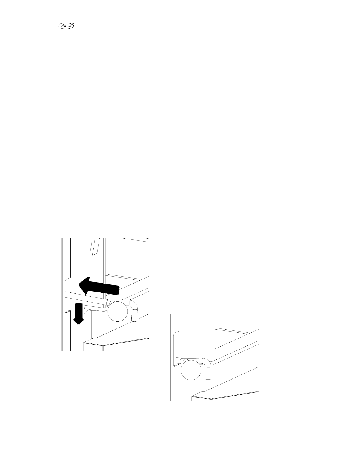
Heating up and operation
Before igniting the fuel, open the feeding door and push the pull rod of the heat up flap back to
the basic position until is the latch fixed (like when the door is closed, see the picture).
Position after the feeding door is open.
Press backwards and downwards
Position after pressing backwards and downwards
Turn the flue gas thermostat to „0 °C“. Put one layer of the medium thick wood logs ( of approx.
50 mm length) through the upper door on a fire proof nozzle. Then, make the layer of thin wood
Page 13

13
with the gap of 2–4 cm and lay splinters or wood wool and paper on it. Continue with 2 layers of
thin dry wood and complete it with the standard firewood. Turn the exhaust fan on and after the
wood is ignited, let the feeding door open for approximately 15 mm. Use the output regulator to
set the required water temperature (80–90 °C). When the fire is strong enough (after
approximately 10 minutes), close the feeding door. Set the flue gas thermostat to the operating
temperature (white mark upwards, approximately 90° to the right from the zero position – it
depends on the flue gas temperature required to stop the boiler after the fuel burns out).
WARNING: The pull rod of the heat up flap has to be pushed backwards to close the
heat up flap. Otherwise the fan could get damaged.
For wood gasification in the boiler it is necessary to keep the reduction layer during the
operation (the layer of wood coal on the nozzle in the feeding chamber). Therefore it is
necessary to burn dry wood of a suitable size. When the wet wood is burned, the boiler does not
work as a wood gasifying boiler, the wood consumption rises, the output is not sufficient and
service life of the boiler and of the chimney is shortened.
When there is a prescribed chimney draught, the boiler works up to 70 % of its output even
without the fan.
Electromechanical boiler regulation
The boiler is regulated by the boiler thermostat placed on a boiler panel which controls the fan
according to the adjusted output temperature of water. The required operating boiler
temperature should be set on the boiler thermostat. The flue gas thermostat placed on a panel
serves to stop the fan after the fuel burns out. Set the flue gas thermostat to “0 °C” when heating
up. When the fire is sufficient, set it to the operating position to let the fan run and to stop it after
the fuel burns out. The optimal position of the flue gas thermostat has to be found by
experience, adequately to the fuel used, chimney draught and other conditions. The output
temperature of water is indicated on thermo-manometer. The irreversible safety thermostat is
also placed on the front panel (the STANDARD and LAMBDA version).
Refilling the fuel
When refilling the fuel, open the feeding door. The heat up flap is opened at the same time. Do
not stop the fan. Always keep the feeding chamber full when heating up. Not to let the smoke
flow into the boiler room, refill the fuel after it is burned to approximately 1/3 of the feeding
chamber. Cover the glowing coal with a wide wood log and refill the fuel normally. Do not press
the fuel on the nozzle, otherwise it could get clogged and the parameters of burning would be
worse.
Page 14
14
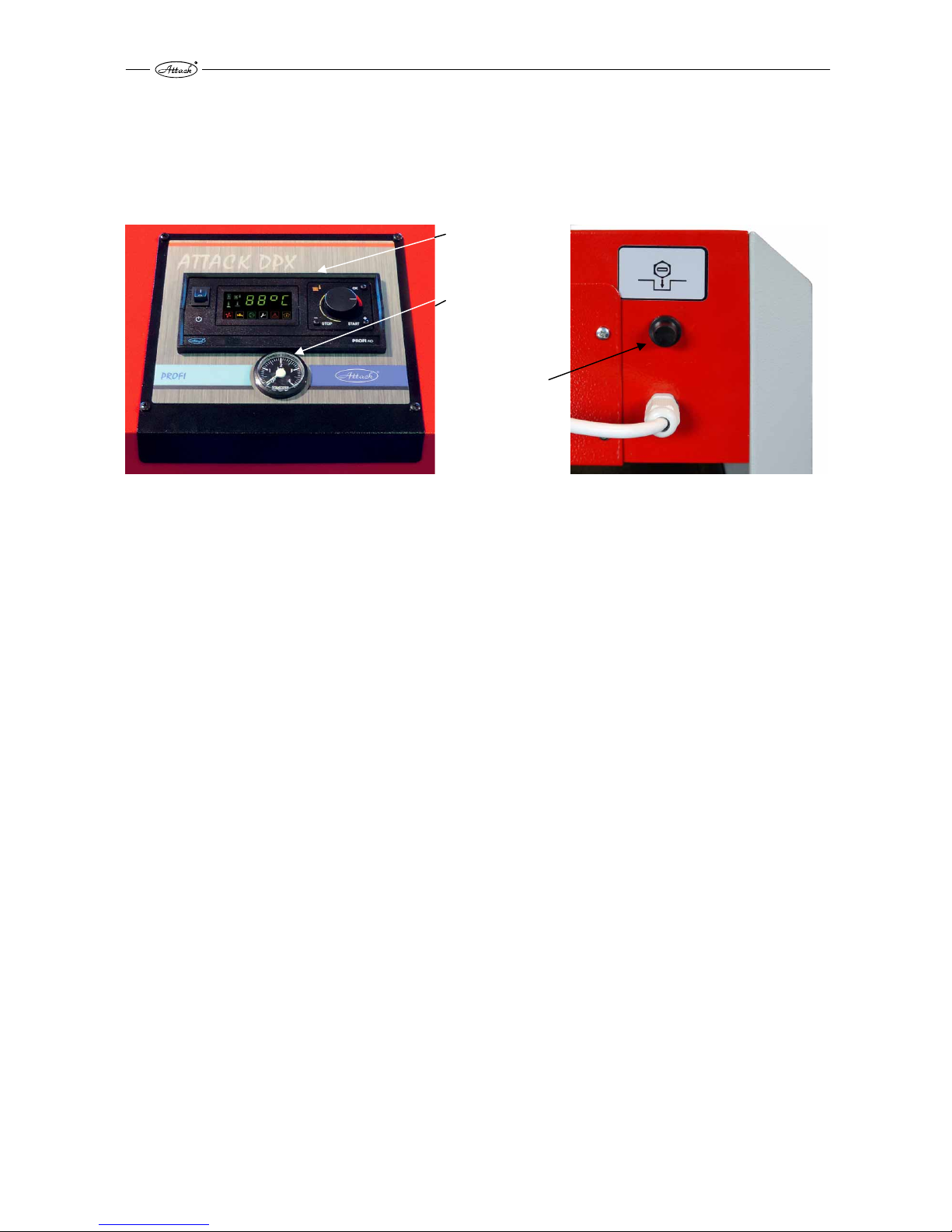
3 TECHNICAL DESCRIPTION OF THE ATTACK DPX PROFI
The ATTACK PROFI boiler version in comparison with the ATTACK STANDARD version brings the
higher comfort of operation, option of output regulation and option to connect the control and
regulation devices.
1. Electronic
regulator
PROFI
2. Manometer
3. Safety
thermostat
The safety thermostat is placed on the rear side of the control board.
3.1 ADVANTAGES OF THE REGULATOR
The ATTACK PROFI PID is a sophisticated regulator for wood gasifying boilers DPX. There is an
improvement of regulation – the flue gas temperature is controlled by the PID.
The regulator can control:
1. Rotations of flue gas fan
2. Circuit pump of heating circuits
3. Pump for warming the D.H.W. or pump for warming the accumulation tank (always just one)
4. Starting another, automatic boiler, if the fuel in the boiler burned out
The regulator measures the following:
1. Boiler temperature
2. Flue gas temperature
3. Temperature in the D.H.W. tank or in the accumulation tank (always just one)
4. Room thermostat and thereby it controls the circuit pump
Page 15
15
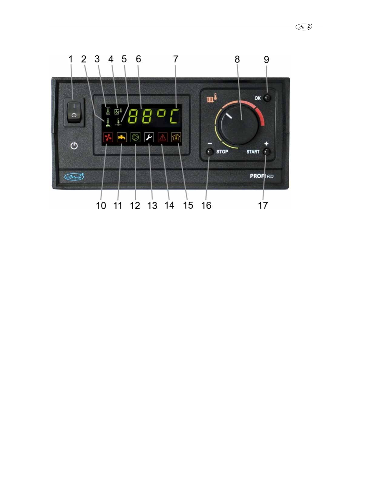
3.2 BASIC DESCRIPTION OF THE REGULATOR
KEY:
1. main switch
2. icon for D.H.W. temperature
3. icon for temperature of accumulation tank
4. icon for flue gas temperature indication
5. icon for current boiler temperature
6. current boiler temperature (or temperature of D.H.W., flue gas, etc.)
7. sign for boiler operating mode
8. setting the boiler temperature
9. button to enter into the information menu, service menu and confirmation of parameters
10. icon for fan operation
11. operation of the pump for D.H.W. or for accumulation tank warming
12. icon for circuit pump operation
13. icon for enter into the service menu
14. icon indicating overheating or damaged sensors
15. icon indicated that the room thermostat is started
16. button to stop the boiler or to move backwards in menu
17. button to start the boiler or to move forwards in menu
Page 16
16
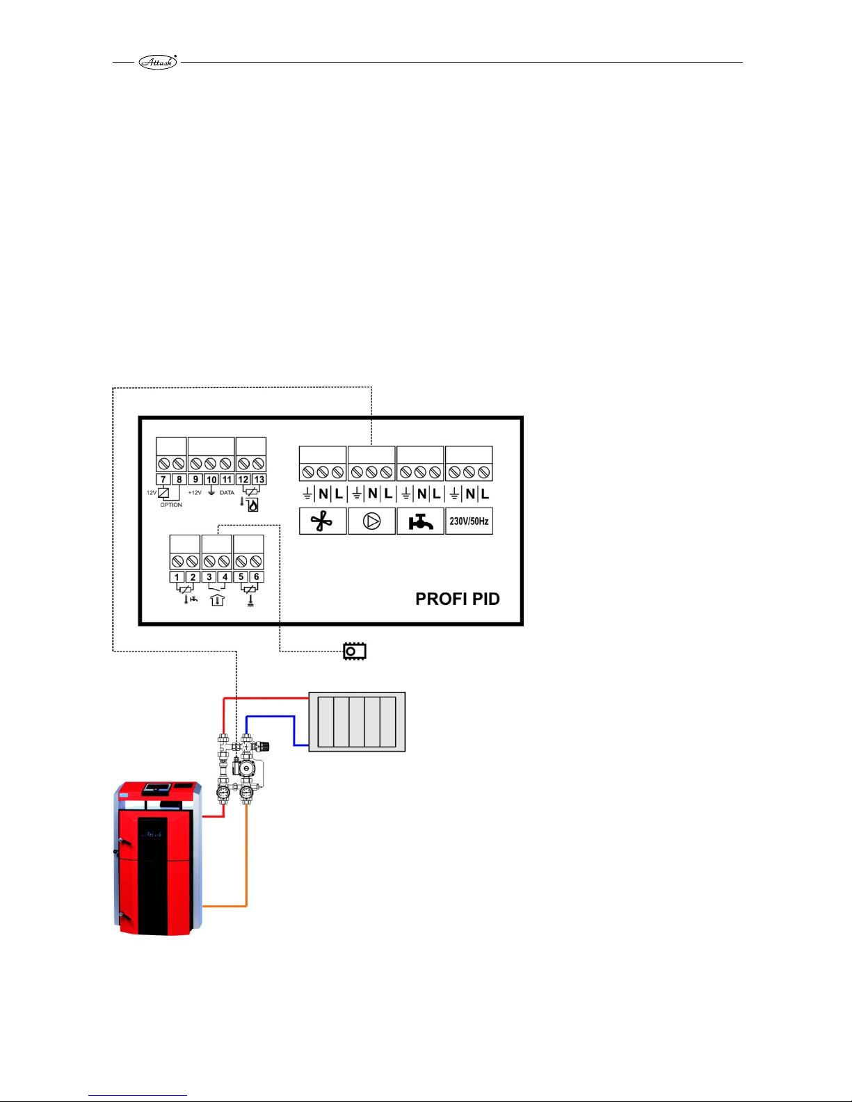
3.3 CONNECTION OF THE REGULATOR BY HYDRAULIC SCHEMES
The regulator can control several types of hydraulic schemes. Parameters in the service menu
must be correctly set adequately to the type of the hydraulic scheme.
Note: The additional thermal probe to control the additional output is connected by production
and it is rolled in the control panel of the boiler. To use the probe it is necessary pull it out from
the control panel through the prepared plastic bushing. This action can be performed only by a
qualified person or by a person trained by producer. The regulator is set by production for the
simple control of heating circuit following the scheme 3.1. On the below mentioned schemes
there is connection of the pumps and sensors. Correct connection of the pumps and sensors is
given on schemes. Connection of the fan and connection of the regulator to the electricity mains
is not drawn.
3.3.1 WOOD GASIFYING BOILER + HEATING CIRCUIT
Parameter setting for the hydraulic scheme 3.1:
ur = ur0
Page 17
17
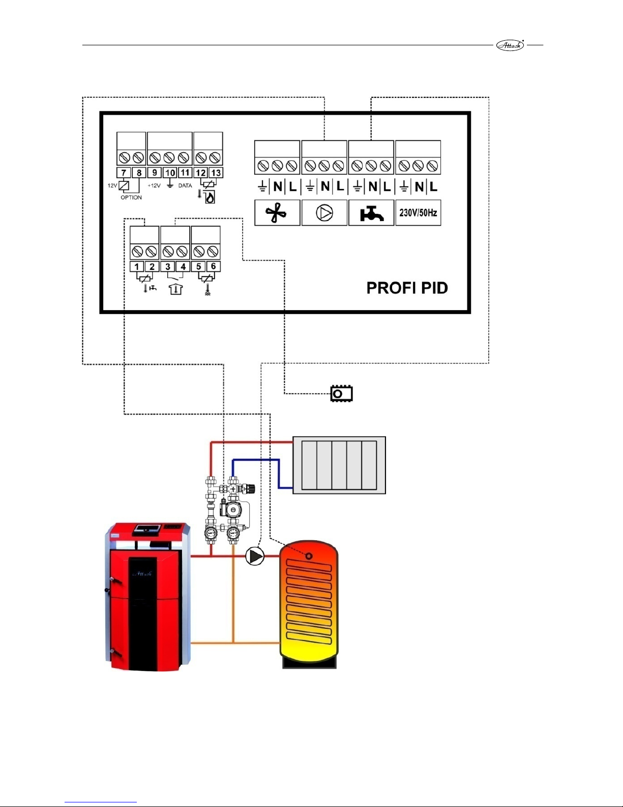
3.3.2 WOOD GASIFYING BOILER + HEATING CIRCUIT + WARMING OF D.H.W.
Parameter setting for the hydraulic scheme 3.2:
ur = ur1 – for priority charging of the D.H.W. tank
ur = ur2 – for paralel charging the D.H.W. tank
Page 18
18
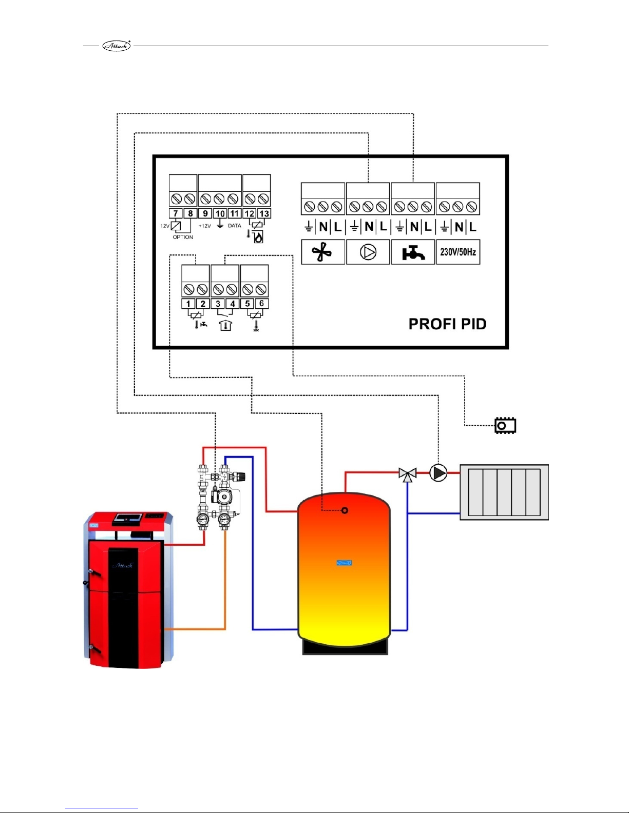
3.3.3 WOOD GASIFYING BOILER + HEATING CIRCUIT + WARMING OF
ACCUMULATION TANK
Parameter setting for the hydraulic scheme 3.3:
ur = ur4
Page 19

19
3.3.4 WOOD GASIFYING BOILER + HEATING CIRCUIT + WARMING OF
ACCUMULATION TANKS CONNECTED IN SERIE
Parameter setting for the hydraulic scheme 3.4:
ur = ur4
Page 20

20
3.3.5 WOOD GASIFYING BOILER + HEATING CIRCUIT + WARMING OF THE
COMBINED ACCUMULATION TANK
Parameter setting for the hydraulic scheme 3.5:
ur = ur4
Page 21

21
3.4 REGULATOR CONTROL AND OPERATING MODES
Turning on the controller is signalized by a brief switching on all the light indicators on display
to enable to check their status. If the regulator gets suddenly disconnected from electricity
mains (e.g. by power failure), it is switched to the last mode used, when the failure occurred. All
the settings made are saved even after the power failure.
The basic setting of the controller is the adjustment of the boiler temperature by the knob. Other
functions are controlled adequately to the service parameters set in the service menu.
The boiler is turned on by pressing the START (17) button that starts the fan. The STOP (16)
button switches the boiler off by turning the fan off.
The sign displayed behind the numeric temperature indication (7) is related to the current
mode of the PID PROFI regulator:
[50°–] – indicates the stand-by mode
[50 °C] – indicates the winter operating mode
[50 °C] – indicates the winter operating mode when the boiler temperature is achieved
[50°U] – indicates summer operating mode intended only for D.H.W. preparation
[50°u] – indicates summer operating mode when the boiler temperature is achieved
[70°d] – indicates mode of elimination the legionella bacteria, when the temperature of D.H.W.
is increased to 75 °C
[50°P] – indicates that regulator is blocked by pellet burner of the COMBI PELLET boiler
The PROFI PID regulator has an advantage of regulating the flue gas temperature to the required
value.
The controller struggles to achieve the adjusted flue gas temperature and after it is achieved, the
required boiler temperature is to be reached. Thereby is the fuel used in the best way and the
high efficiency is achieved.
When loading the fuel, it is necessary to hold the START button (for approximately 3 sec.).
Rotations of the fan are increased to 100 %. Therefore it is ensured that the flue gas created in
the loading chamber is sufficiently sucked and no smoke gets into the boiler room. The fan gets
back to the regulation of rotations after the period defined by the parameter Md3.
Page 22

22
3.5 SETTING THE USER PARAMETERS
The menu for displaying and setting the user parameters is accessible after short pressing of the
OK button. The „+“ and „–“ buttons are used to browse in settings and parameters. The
appropriate parameter selected becomes adjustable by the „OK“ button and starts to flicker.
Then it can be changed by the „+“ and „–“ button and confirmed by „OK“. Some of the
parameters are only informative and they cannot be changed. To exit the menu, confirm the
[End] by „OK“ button. After remaining more than 1 minute without the user´s intervention, the
controller switches the display to the basic mode.
Table 2. User parameters:
Indication Parameter Min Max Step Prod. setting
C 45 Adjusted boiler temperature L65 H90 1 °C –
co C
Operating mode of the circuit pump (‘C’ –
WINTER, ‘–‘ – SUMMER)
C
–
C
cu u
Operation of the D.H.W. pump (‘u’ – casual
mode, ‘d’ – elimination of legionella bacteria)
u d u
u50°
Current temperature measured in the
accumulation tank or D.H.W. tank
150° Current flue gas temperature
End Exit from user parameters
[C 45] – Adjusted boiler temperature – this is the value of boiler water temperature the
regulator is going to reach while in the WORK mode. It is set by turning the thermostat knob
manually (8) and shown briefly on the display (6).
[co C] – WINTER/SUMMER mode – the winter mode is indicated by the ‘C’ letter. Then is the
circuit pump controlled by the room thermostat and distributes the heat into the heating
system. The summer mode is indicated by the „–“ sign. Then is the circuit pump out of order and
the heat generated by boiler is only used to heat the D.H.W. tank. If there is not D.H.W. tank in
the system (additional sensor is not connected), it is not possible to select the SUMMER / WINTER
mode.
[cu u] – Mode of D.H.W. tank warming – the regulator enables the casual D.H.W. tank warming
„u“ or the mode to eliminate the legionella bacteria „d“. After the „d“ mode is selected, the
temperature of 75 °C is achieved in the D.H.W. tank. When this temperature is achieved, the
controller switches into the mode of the casual D.H.W. tank warming „u“. The option of
elimination the legionella bacteria is not available, if the additional outlet and sensor are not set
for the D.H.W. warming.
CAUTION! Not to get hurt by the hot water, it is recommended to set this mode, when
the D.H.W. is not being used (e.g. during the night).
[u50°] Temperature of additional sensor – this is the value of current temperature of the
D.H.W. tank or of the accumulation tank of the heating system. This temperature is not displayed
in the user menu, if the additional output is not used.
[150°] Flue gas temperature – this value represents the current temperature of flue gas, if the
parameter for flue gas temperature is set in the service parameters.
Page 23

23
3.6 SETTING THE SERVICE PARAMETERS
By holding the OK button you get into the service menu to the parameter settings (the icon
(13)). The buttons „+“ and „–“ are used to browse in particular parameters. After selecting the
appropriate parameter, it is confirmed by „OK“ button and starts to flicker. To exit the menu,
confirm the [End] by „OK“ button. After remaining for more than 1 minute without the user´s
intervention, the controller switches the display to the basic mode.
Table 3. Service parameters:
SERVISCE MENU (available by holding the OK button)
Display Parameter Min Max Step Prod. set.
Π100
Maximum fan output 1 100 1% 100
n 40
Minimum fan output 1 100 1% 40
Πh 5
Ratio of changing the fan rotations 2 20 1 5
Πr 0
Automatic regulation of changing the fan rotations –, 0 10 1 0
Πt 1
Delay of changing the fan rotations 0 99 1 1
Πn 5
Frequency of exhaust fan blow-through --, 5 60 1s 5
Πu 6
Duration of exhaust fan blow-through 1 99 1min 6
Πd3
Duration of manual fan operation for 100% --, 1 99 1min 3
r100
Fan output by ignition 1 100 1% 100
rh 5
Hysteresis of boiler stop by ignition 1 45 1 °C 5
P 30
Temperature to start the circuit pump --, 20 70 1 °C 30
Ph 2
Hysteresis of circuit pump 1 40 1 °C 2
Pc --
Interval of unlock function of circuit pump --, 1 99 1min 2
ur4
Operation of additional output 0 4 1 4
u30
Operating temperature of D.H.W. tank or accumulation tank 30 60 1 °C 30
uh 5
Hysteresis of D.H.W. tank of accumulation tank 1 30 1 °C 5
uP 5
Boiler temperature increase by D.H.W. warming 1 20 1 °C 5
L65
Minimum boiler temperature 30 65 1 °C 65
H 85
Maximum boiler temperature 80 95 1 °C 85
h 2
Boiler temperature hysteresis 1 10 1 °C 2
A 99
Temperature of boiler overheating 90 99 1 °C 99
Fd60
Duration of boiler stop by ignition and fuel shortage --, 1 99–4h 1min 60
Fb30
Duration of boiler stop by flue shortage and burn-down --, 1 99–4h 1min 30
Ar 0
Control of multifunctional additional output 0 1 1 0
c 240
Adjusted flue gas temperature –0,5 250 1 °C 240
c h5
Flue gas temperature hysteresis 1 99 1 °C 5
c t 5
Time constant of stabilization the flue gas temperature 1 99 1 min 5
c F10
Blower speed jump while stabilizing flue gas temperature 1 20 1 °C 10
c 90
Flue gas temperature by fuel shortage 30 150 1 °C 90
c 300
Maximum flue gas temperature 250 400 1 °C 300
Prod
Reset of production settings
outΠ
Test of fan relay outΠ out1
outP
Test of circuit pump relay outP out2
outu
Test of relay of optional pump outu out3
outr
Test of additional output outr out4
End
Exit to main menu
Page 24

24
3.7 DESCRIPTION OF PARAMETERS
[Π100] Maximum fan output – the highest fan output possible
[n 40] Minimum fan output – the lowest fan output possible
[Πh 5] Ratio of changing the fan rotations – this parameter influences the fan rotations, if the
adjusted boiler temperature is going to be achieved in a short time. For example, if the value 4 is
set, the fan will work at full output [Π100] (if the function of flue gas temperature control is not
active), up to 4 degrees before achieving the required boiler temperature. Then, by every
increase of the boiler temperature for 1 °C, the fan rotations are gradually decreased until the
minimum fan output is reached [n 40].
[Πr 0] Automatic regulation of changing the fan rotations – the fan rotations are increased /
decreased by setting this parameter within the range of 0–10 to ensure the required boiler
temperature. If this parameter is set to „- -“, the rotations are not controlled and the fan works at
full output according to the parameter [Π100]. Setting the parameter within the range of 0–10
relates to the time period (in minutes), during which are the fan rotations gradually increased
from the parameter of the minimum fan rotations [n 40] up to the parameter [r 100]. This
ensures the fluent heat-up of boiler.
[Πn 5] Frequency of exhaust fan blow-through – this frequency defines, how often the fan is
started to the full output [Π100] to take the flue gas out from the boiler, if the fan was stopped
due to the boiler temperature achieved.
[Πu 6] Duration of exhaust fan blow-through – during this period must the fan exhaust the
flue gas following the parameter [Πn 5].
[r 100] Fan output by ignition – this parameter defines the fan output by boiler heat-up. If the
parameter " Πr " is set to [Πr 0], then this parameter is not available.
[rh 5] Hysteresis of boiler stop by ignition – defines, how many degrees before reaching the
required boiler temperature will be the heat-up phase finished or (if the flue gas temperature
sensor is connected), how many degrees before reaching the required flue gas temperature are
relevant to stop the heat-up phase. After deactivation of the heat-up phase there is a casual
operating mode.
[P 30] Temperature to start the circuit pump – if there is not D.H.W. tank in the system [ur 0] or
it is in the mode [ur 2], then the parameter defines the boiler temperature for starting the circuit
pump of the heating system. If the parameter is set to „- -“, then too low temperature does not
influence the operation of the circuit pump. Anyway, the pump is always started, when the
boiler temperature exceeds the parameter [H 85] of the maximum boiler temperature.
If there is accumulation tank in the system (parameter [ur 4]), then this parameter defines the
temperature measured in the accumulation tank by which is the circuit pump of the heating
system started.
[Ph 2] Hysteresis of circuit pump – defines the temperature difference under which must the
boiler temperature or temperature in the accumulation tank decrease in comparison with the
temperature defined by the parameter [P 30] to stop the circuit pump.
Page 25

25
[Pc --] Interval of unlock function of circuit pump –when controller is in the stand-by mode or
the room thermostat is disconnected, the circuit pump is started for 30 seconds after each [Pc --]
minutes to prevent the pump blockage caused by its inactivity. The unlock pump function is not
active, when the Pc is set to „- -“.
[ur 0] Operation of the additional output – this parameter defines the operating mode of the
additional output (pump for D.H.W. tank or accumulation tank warming).
[ur 0] Additional output without function – defines that the additional output and pump are
not connected and the additional output is not used in this case.
[ur 1] Priority D.H.W. tank warming – by this setting is the pump for D.H.W. tank warming
connected to the additional output and the sensor of D.H.W. is connected to the additional inlet.
Then, if the temperature in the D.H.W. tank decreases under the value of hysteresis
[uh 5] from the temperature adjusted [u 60], the pump of D.H.W. tank warming is started. After
the temperature in the D.H.W. tank reaches the set value [u 60], the pump is stopped. The pump
is also stopped, when the temperature in boiler is lower than the temperature in D.H.W. tank.
The [ur 1] mode means that the D.H.W. warming has priority, i.e. the pump of the heating circuit
is started after the D.H.W. is prepared.
[ur 2] Parallel charging the D.H.W. tank – similar principle as by the [ur 1], just the D.H.W. is
prepared by the parallel operation of the circuit pump of the heating circuit.
[ur 3] Unused
[ur 4] Charging the accumulation tank – due to this setting is the additional output used as
a pump to heat the accumulation tank and the additional sensor measures its temperature.
When the temperature in the boiler exceeds the hysteresis [uh 5] over the current temperature
of accumulation tank, the pump for charging is started. The pump is stopped, when the
temperature in the boiler is same or lower than the temperature in the accumulation tank, or
when the temperature in boiler decreases under the minimum boiler temperature defined by
the parameter [L 65].
[u 30] Operating temperature of the D.H.W. tank or accumulation tank – temperature to
control the additional output [ur ].
[uh 5] Hysteresis of the D.H.W. tank or accumulation – this parameter defines hysteresis of
the additional output [ur ].
[uP 5] Boiler temperature increase by D.H.W. preparation – this parameter is relevant, when
the additional output works under the mode of D.H.W. tank charging. It defines, for how many
degrees will the adjusted boiler temperature be higher than parameter [u 50] during the D.H.W.
tank warming.
[L 65] Minimum boiler temperature – defines the minimum boiler temperature that can be set
by a knob.
[H 85] Maximum boiler temperature – defines the maximum boiler temperature that can be
set by a knob.
Page 26

26
[h 2] Hysteresis of boiler temperature – defines the difference between the adjusted and the
current boiler temperature for which must the boiler temperature decrease to start the
controller again after the adjusted boiler temperature is achieved.
[A 99] Temperature of boiler overheating – defines the value of boiler temperature to activate
the alarm of the boiler overheating.
[Fd60] Duration of boiler stop by ignition and fuel shortage – this parameter defines the
maximum time between starting the controller by the START button and achieving the
controller´s operating mode (reaching the flue gas temperature of [c 90]). If the temperature of [c
90] is not reached during the heating up, the fan is stopped and the alarm FUEL (fuel shortage) is
displayed.
[Fb30] Duration of boiler stop by flue shortage and burn-down – the fuel amount test is
activated in the operating mode, when the flue gas temperature decreases under the parameter
[c 90] or (if the flue gas sensor is not connected) when the boiler temperature decreases under
the adjusted parameter [L 45]. If the temperature does not exceed the necessary limit during this
period, the controller displays FUEL alarm.
[Ar 0] parameter – indicates start of the automatic boiler (e.g. gas or pellet boiler). When the
controller is started and the boiler generates heat, the automatic boiler is stopped. Operation
of the automatic boiler is blocked by the controller in the operating mode. The automatic
boiler is started by controller, when the fuel is burned down in the boiler and the FUEL alarm
is displayed.
[Ar 1] parameter – indicates that the additional multifunctional output will be used for error
messages like boiler sensor failure, overheating or fuel shortage.
[c 240] Adjusted flue gas temperature – the controller will struggle to reach and to keep this
value. The flue gas temperature sensor is turned off, if this parameter is set to „- -“.
[c h5] Hysteresis of flue gas temperature – defines the difference for which must the flue gas
temperature decrease to increase the fan rotations.
[
c
t 5] Time constant of stabilization the flue gas temperature – defines the period of
adjusting the fan rotations during stabilization of the flue gas temperature. If the flue gas
temperature exceeds the value given by the parameter [
c
240], the controller starts to decrease
the fan rotations gradually, until the flue gas temperature decreases to the adjusted value. If the
flue gas temperature decreases to the value of flue gas temperature hysteresis, the controller
starts to increase the fan rotations gradually.
[c F10] Blower speed jump while stabilizing exhaust gas temperature – defines the change
of rotations to achieve the adjusted flue gas temperature.
[c 90] Flue gas temperature by fuel shortage – the message „FUEL“ for fuel shortage is
displayed after the flue gas temperature decreases under this value.
3.8 TESTING THE REGULATOR OUTPUTS
It is possible to make a check to test the correct functionality of the regulator and devices
connected. The correct function of fan is tested by selecting the [outΠ] on display and holding
the „OK“ button. Test of the circuit pump is done by selecting the [outP]. Select the [outu] to
start the additional output and [outr] for multifunctional additional output.
Page 27

27
3.9 RESET OF THE REGULATOR´S PRODUCTION SETTINGS
There is a possibility to reset the production settings of the regulator by selecting the [Prod] in
the service menu and confirming by „OK“ button. Then is the regulator set to the values given in
the Table 3.
3.10 EXIT FROM SERVICE MENU
Select the [End] on display and press the „OK“ button to exit from service menu.
3.11 ERROR MESSAGES
The connection of all sensors of the regulator is permanently monitored. If the regulator detects
that some of the sensors is not connected, the error messages are displayed. Messages about the
boiler overheating or fuel shortage are also displayed.
Error messages displayed
[FUEL] – is displayed, when there is not enough fuel in the boiler. The sufficient amount of fuel is
defined by the parameter c90, where the figure 90 is related to the adjusted value 90 °C. Then, if
the flue gas temperature decreases under this adjusted value within the time Fb30 (time of
boiler stop by fuel shortage), the regulator displays the [FUEL] message. To start the boiler again,
it is necessary to remove the message by the STOP button and then to press the START.
[HOT] – is displayed, when the flue gas temperature exceeds the maximum permitted value set
by the parameter c300 (means 300 °C). The ventilator is stopped in this case. After the
temperature decreases under the adjusted flue gas temperature, the ventilator is started again.
[E 1] – is displayed, when the boiler temperature sensor fails or when it is not connected. In such
case is the regulator taking actions to ensure the safety of the boiler – the fan is stopped (if it is
currently in operation) and the circuit pump is started for eventual safe boiler cooling. After the
cause of error is removed, the error message can be erased by the STOP button.
[E 2] – is displayed, when the boiler temperature exceeds the boiler overheating temperature
A99. The regulator stops the flue gas fan and starts the circuit pump. The error message can be
removed by the STOP button after the boiler temperature decreases to the safe value.
[E 8] – is displayed, when the additional sensor fails (in the D.H.W. tank or accumulation tank). If
this sensor works for the D.H.W. tank, the warming is blocked. If the sensor works for the
accumulation tank, the pump will be permanently working. This error message cannot be
removed by the STOP button. It is automatically erased after the sensor failure is repaired.
[E128] – is displayed, when the flue gas temperature sensor fails. In this case is the boiler control
switched to regulate according to the boiler temperature. The error message is erased
automatically after the fault of the flue gas temperature sensor is solved.
[E 3] If several failures occur in one moment, their total is displayed. In such case it is necessary to
check the functionality of all sensors.
Page 28

28
3.12 DISASSEMBLY OF THE REGULATOR
If it is necessary to disassemble the regulator, do the following:
turn the main switch off
disconnect the boiler from electricity mains
demount the regulator
demount the connectors from the regulator
3.13 TECHNICAL SPECIFICATION OF THE REGULATOR
Power supply 230V + 10%, 50Hz
Input (not including the ventilator and pumps) < 4VA
Range of measuring the boiler temperature –9 – 109 °C + 1 °C
Range of measuring the flue gas temperature –30–500 °C + 1 °C
Max. input of devices connected to the regulator 2A/230V
CAUTION: not to get injured by the electrical current, do not remove the cover of
device before disconnecting it from electricity mains!
Page 29

29
4 TECHNICAL DESCRIPTION OF THE ATTACK DPX LAMBDA
4.1 REGULATION OF BURNING
The boiler output is regulated according to the flue gas temperature by the air inlets to the
particular oxygen value. The flue gas temperature for burning down is adjusted. If there is a lot of
fuel (totally full feeding chamber) and the boiler temperature achieves 90 °C (overheating), the
flue gas fan is stopped, flap for primary air is closed and flap for secondary air is open for 25 %.
When the boiler temperature decreases to less than 88.5 °C, the flap for secondary air is for 30
seconds open for 100 % (chimney cleaning) and the primary air flap is regulated according to the
requirement for the flue gas temperature.
Automatic boiler stop: After the fuel burns out, the boiler can be stopped automatically or by
setting the flue gas temperature (TAG) or by a setting the value for oxygen (optional function).
Boiler stop by setting the flue gas temperature: When the fuel burns out and the flue gas
temperature decreases to less than 25 % of the adjusted value, the boiler stops after 15 minutes.
This is recommended only when the big or wet wood logs are being used.
Stop by the oxygen value: If the boiler works for more than 45 minutes and the oxygen value
exceeds 14 % for more than 15 minutes, then the boiler stops. This should be a standard function,
when the boiler cooling by chimney is limited. Ignition with remaining coal is easier and there is
less smoke by heating up.
When the boiler stops, the flue gas fan is stopped, the primary air flap is closed, the secondary air
flap remains open for 25 % until the flue gas temperature decreases below 100 °C.
Automatic restart after the power shortage: After the power shortage, the secondary air flap is
open for 100% for 30 seconds to let the chimney clean.
Overheating (boiler temperature above 90˚C): The secondary air flap remains open for at least
25 %.
After turning the boiler off (automatically or manually): The primary air flap V1 is closed (0%),
the flue gas temperature is above 100 °C, the secondary air flap remains open for at least 25 %
and function of the automatic operation is inactive.
4.2 IGNITING AND REFILLING THE FUEL
Basic instructions:
Check the pressure (and level of water) in the heating system before igniting.
The fuel has to be prepared in the boiler.
Ignite the fuel (see the prescriptions for boiler operation) and the rest of fuel in the feeding
chamber
4.3 IGNITING OR REFILLING THE FUEL
If it is possible due to the requirement for heat and the rest of the fuel in the feeding
chamber, check the thermometers in the feeding chamber.
Effect: Maximum utilization of fuel
Beginning: When the boiler is stopped (the indicator light 1 does not flash), make the fire as first.
4.4 REFILLING THE FUEL DURING THE BOILER OPERATION
Refill the fuel quickly and close the door immediately.
Page 30

30
4.5 FUNCTION AND DISPLAYING THE TEXT BY IGNITING OR
REFILLING THE FUEL
After pressing the „+“button it comes to the following procedure:
The boiler is started the indicator light 1 flashes and the ignition is running
The text is displayed:
DO NOT OPEN!
WAIT
the flue gas fan and regulation of burning are started
the supply pump and regulation of the return and supply valve are started
the generator of an alternative energy is stopped by the switch
after 5 seconds appears the text:
FUEL DOOR UNLOCKED
and in 10 seconds is the electromagnetic door-lock released (is it is disposable)
after 10 seconds appears the text:
CAUTION!
OPEN SLOWLY!
after 5 seconds appears the text:
IGNITION
Prepare and ignite the fuel following the instructions on the page 11, close the feeding door
partly. If the bar chart is full, the fuel is ignited, close the door.
If the bar chart is full and ignition or process of fuel loading takes more than 15 minutes, it is
switched to the operating display mode.
The regulator stops the boiler after 15 minutes, if:
There was no ignition and the regulator started the burning process despite of that fact,
because it was accidentally started by the „+“button.
The fire extinguished after closing the door, because there was lack of wood splinters or the
fuel is too wet.
4.6 DISPLAY OF THE OPERATING MODE BY THE BOILER STARTED
Text on display:
BOILER TEMPERATURE
˚C
After 5 seconds appears the next text:
FLUE GAS TEMPERATURE
˚C
This text appears on display every 5 seconds.
Page 31

31
4.7 EXCESSIVE FLUE GAS TEMPERATURE
If the flue gas temperature exceeds 300 °C because the feeding door, the door for ignition or the
ashtray door was open for too long time, then appears the text excessive flue gas temperature –
(see display)
In this case: CLOSE THE DOOR IMMEDIATELY!
If the flue gas temperature exceeds 350˚C, the flue gas fan is stopped from safety reasons and
after the temperature achieves 299 °C or less, the flue gas fan is started again. Thereby is the flue
gas fan and the flue gas sensor protected against damage.
4.8 BOILER OVERHEATING
When the feeding chamber is totally loaded with too much of fuel, the boiler temperature rises to
90 °C and more. Then it comes to the state of overheating and the flue gas fan is automatically
stopped. Display flickers with the text:
Overheating
DO NOT OPEN
The boiler door must not be opened. By overheating it comes to the high fuel consumption and
ecological damages.
4.9 DISPLAY OF THE OPERATING MODE WHEN THE BOILER IS OUT
OF ORDER
When there is no more fuel left, the boiler is automatically stopped by regulator or it can be
stopped manually by the „+“button (this serves only for safety stop, e.g. when there is no water in
the boiler). After the boiler is stopped, the following text is displayed immediately:
BOILER TEMPERATURE
˚C
The display illumination is turned off after 15 minutes.
4.10 FUNCTIONS OF THE AUTOMATIC PROTECTION
If the boiler did not heat for 7 days, the flue gas fan is started for 2 minutes and the boiler is
„blown through“ by the fresh air to get dried. The reverse and supply valve are working as well
and the supply pump is started for 10 seconds. The following text is displayed during this
procedure:
PROTECTION FUNCTION
PLEASE WAIT
After completing the protection function is the display automatically switched to the operating
mode.
4.11 INFORMATION ABOUT THE CURRENT OPERATION
The „←“ button enables to enter into the menu „Options“. The first option – „Information“ – is
displayed immediately. By the „←“ button it is possible to enter into the „Information“ menu and
to browse there by the „+” and „–” buttons.
Page 32

32
The „←“ button is used to exit from menu and then is the display automatically switched to the
operating mode. If no button is pressed for 30 minutes, the display automatically is switched to
the operating mode automatically.
If any fault occurs or the temperature rises extremely, the options menu closes automatically.
4.12 INFORMATION DISPLAYED:
Menu Submenu Indication
Information
Boiler set
°C --
Indicates the adjusted temperature value in the boiler
Boiler temperature
°C ---.-
Current value. Indicates the current boiler temperature.
Flue gas set
°C ---.-
Indicates the adjusted flue gas temperature
Flue gas temperature
°C ---.-
Indicates the current flue gas temperature
O2 set
% --.-
Indicates the adjusted oxygen value in the flue gas.
O2
% --.-
Indicates the current oxygen value in the flue gas.
CO2 set
% --.-
Indicates the adjusted value of the CO
2
in the flue gas
CO2
% --.-
Indicates the current
value of the
CO2
Note: The fix value of the CO
2
for calculation is max. 20,3 %.
Suction fan
ON/OFF
Operating state of the fan
Circuit pump
ON/OFF
Operating state of the pump
Primary motor
% --.-
Position of the primary air flap
Secondary motor
% --.-
Position of the secondary air flap
Lambda
--.-
Ratio of air (curr
ent value
) Note:
The fix value of the CO
2
for
calculation is max. 20,3 %.
Efficiency
ETA – F (%) --.-
Grade of efficiency of burning – current value
Temperature of air for burning (35 °C) is used for calculation
Total temperature excess (%)
--.-
Total ratio of the temperature excess (%) during the total time of
burning (total of the operating hours)
Temperature excess –
10 loadings (%) --.-
Ratio of the excessive temperature in (%) by the last 10 loadings.
Operating hours
H --.-
Operating hours of the boiler. After 60 000 hours is the counter
deleted.
Software
--.--
Program version nr.
Serial number
---------
Serial or production number of the regulator.
Test of
device
Safety test
Setting
END
Page 33

33
4.13 SETTING FOR COMMISSION OF THE ATTACK DPX LAMBDA
The device can be commissioned, when the minimum requirements for the testing operation or
heating are fulfilled (see the chapter 1.2). Then it is necessary to make the following settings.
Settings by using the code of the service technician
The button „←“ enables to enter into the menu of Options, where the submenu „settings” can be
changed by the „+“ and „–“. The button „←“ is used to confirm the selection.
Exit from the submenu comes automatically after selecting the „supply valve“ by the button „←“.
Then is the display automatically switched into the operating mode. If no button is pressed
during 1 minute, the display is automatically switched to the operating mode.
Settings:
Menu Submenu Indication
Information
Test of device
Safety test
Setting
Entering the code
---
Set the code by the „+“ button. The random
number is displayed on the left side. Enter the
code and confirm by the button „←“. The code
for service technician is available by producer.
01 :Language
German DE
English GB
Spanish ES
Italian IT
French FR
Swedish SE
Polish PL
Slovak SK
Czech CZ
Dutch NL
Danish DK
Hungarian HU
Slovenian SI
Fun
ction: Setting the national language
02: Boiler setting
°C 85
Function: Set the temperature in the boiler
Producer: 85 °C
Range for setting: 75–85 °C
03: TAG setting
°C 180
Fun
ction: Setting the flue gas temperature
(nominal boiler output 180 °C).
Producer: 180 °C
Range for setting: 110–240 °C
Note: TAG = flue gas temperature
04: O2 setting
% 6,0
Fun
ction: Setting the O2 value for burning 6 %
Producer: 6,0 %
Range for setting: 4,0–8,0 %
05 : TAD start
K 60
Fun
ction: To get the sufficient output of
heating before closing the feeding door
Producer: 60K
Range for setting: 25K d – 125K
Note: TAD = temperature difference.
Difference between the flue gas temperature
and the temperature in the boiler.
Page 34

34
06 : Disconnection
O
2
TAG
Fun
ction: The boiler for wood burning turn off
after burning out due to
O2 – indicates higher amount of the rest coal
(easier start)
TAG – indicates the minimum rest coal
(recommended by problems with burning –
shapeless or wet fuel)
Producer: O2
Setting: O2/TAG
10 : V1 primary air
Air (%) 85
Fun
ction: When the
re is a flue gas sensor or
oxygen fault, it is regulated to the adjusted
value. This is a temporary solution until the
fault is removed – it is not a normal operating
function!
Producer: 85 %
Range for setting: 0 % – 100 %
11 : V2 secondary air
Air (%) 40
Fun
ction: When there is a flue gas sensor or
oxygen fault, it is regulated to the adjusted
value. This is a temporary solution until the
fault is removed – it is not a normal operating
function!
Producer: 40 %C
Range for setting: 0 % – 100 %
END
After the settings are done, the test of device is performed, its correct functionality is checked
and the safety test is made.
Page 35

35
4.14 CANCELLATION OF THE PRODUCER´S FUNCTION
For this procedure you need the code from producer. It is possible to set the operating hours of
the boiler, number of overheating states and the last 10 burnings to 0.
Enter and exit from the appropriate submenu is the same as it is given in the chapter 8.1. If no
button is pressed within 1 minute, the regulator automatically switches to the operating mode.
Option Submenu Indication
Information
Test of device
Safety test
Setting
Code
---
Enter the c
ode from producer by the „+“ button.
The random number is displayed on the right
side. Change it to the code from producer and
confirm by the button „←“. The next setting is
displayed.
Cancel
NO/YES
Select „YES“ by the „+“ button. After pressing the
„←“ button is the explanation of the setting
displayed and the menu is closed.
By selecting „YES“ you can set the boiler
operating hours and the total excessive
temperature, the last 10 burnings are set to 0.
33: Output reduction
NO/YES
Select „YES“ by the „+“ button. After pressing the
„←“ button is the explanation of the setting
displayed and the menu is closed.
By selecting „YES“, the boiler output is reduced
by 20 % is the boiler temperature exceeds the
adjusted temperature for 2K.
End
Testing
The test of device and safety test have to be done by the presence of the technician!
Test of device
The test of device can be done only when the boiler is turned off!
The test can be done, only when there is no danger of overheating!
The test is selected and done by the menu button „←“ (enter into the menu of Options). In the
next menu there is a „test of device“ found by the „–“ button and the confirmed by the button
„←“. The appropriate step of the test is activated by the „+“ button and deactivated by the „–“
button. The next step is selected by the „←“ button.
The test of device is completed after the last point of the test by the „←“ button and the display is
automatically switched to the operating mode. The test can be interrupted by pressing the
buttons „+“ and „–“ at once.
If no button is pressed within 15 minutes, the display is automatically switched to the operating
mode.
Page 36

36
Option Submenu Indication
Information
Test of device
O2 scales
End of the test (+, –)
After pressing the „+“ button is the text „calibrate“
displayed
The calibration takes approx. 600 seconds.
Automatic calibration is done only in the case that
the boiler did not burn for 48 hours and the
operating time of the sensor is higher than 200
hours. By the manual setting there must be no fire
in the boiler, nor the glowing rest of the fuel! If it is
not necessary to adjust the scale, press „←“ and
the next step is displayed.
Note: For quick exit from menu press „+“ and „–“ at
once.
Flue gas fan
End of the test (+,–)
By pressing +
start the flue gas fan
By pressing – stop the flue gas fan
By pressing ← select the next point of the test
Circuit pump
End of the test (+,–)
By pressing +
start the circuit pump
By pressing – stop the circuit pump
By pressing ← select the next point of the test
Primary motor
End of the test (+,–)
By pressing +
open the primary air flap
By pressing – close the primary air flap
By pressing ← select the next point of the test
Secondary motor
End of the test (+,–)
By pressing + open the secondary air flap
By pressing – close the secondary air flap
By pressing ← select the next point of the test
Illumination
End of the test (+,–)
By pressing + turn the text display illumination on
By pressing – turn the text display illumination off
By pressing ← select the next point of the test
Indicator light 1
End of the test (+,–)
By pressing +
turn the
indicator light
1 on
By pressing – turn the indicator light 1 off
By pressing ← select the next point of the test
Indicator light 2
End of the test (+,–)
By pressing +
turn the
indicator light 2 on
By pressing – turn the indicator light 2 off
By pressing ← select the next point of the test
Indicator light 3
End of the test (+,–)
By pressing +
turn the
indicator light
3 on
By pressing – turn the indicator light 3 off
By pressing ← select the next point of the test
Safety test
Setting
END
Page 37

37
4.15 SAFETY TEST
The safety test can be done only in the case that the boiler is started and working for at least
1 hour to make its output adequate to the normal operation.
The test is selected and performed by the „←“ button (enter into the Options menu). Select the
test by the „–“ button and confirm by the „←“ button. The safety test is started automatically.
During the test it is possible to hold the „+“ button for 30 seconds not to let the test process
automatically terminated (see the explanation in the table below).
There is the time limit of 30 minutes for the test. It is automatically stopped or interrupted, if:
1. the boiler temperature increases above 110 °C
2. the „+“ button has not been pressed within 30 seconds.
Then the regulator automatically switches to the operating display mode.
Menu Submenu
Indication
Information
Test of device
Safety test
Time limit of 30 minutes for the test
Safety test +
(sec) 30
Boiler temperature
( °C) --,-
After selecting the test it is necessary to
press or to hold the „+“ button for 30
seconds. Otherwise is the test
automatically interrupted.
If the boiler temperature increases to
95 °C or 100 °C, the STB is started and
the fan is stopped. After few seconds
the following text appears on display
„STB started“. It means that the STB test
has been successfully performed.
After pressing the „+“ button again, the
circuit pump stays stopped until the
temperature of 110 °C is achieved to
test the boiler protection against
overheating.
The boiler temperature has to be kept
under 110 °C which means that the test
of protection against overheating has
been successfully performed or
completed.
Setting
END
Page 38

38
4.16 MAINTENANCE OF THE HEATING SYSTEM AND THE BOILER
It is necessary to check, eventually to refill the water in the heating system at least 1x in 14 days.
If the boiler is out of order during the winter period and the water could freeze in the heating
system, then the water should be replaced with an antifreeze mixture approved by the producer
or it should be discharged out of the system. Normally should be the water discharged only in
urgent cases and for ash short time as possible. At the end of the heating season it is necessary
to clean the boiler properly and to replace the damaged parts. Twice a year it is necessary to
dismantle the fan, to clean the radial impeller and to clean the fan air chamber.
Exchange of the sealing cord of the door
Undo the worn sealing cord by the screw driver and clean the groove, where it was laid. Take the
new sealing cord and put its ends into the horizontal parts of the groove. Use your hand,
eventually a hammer to press the cord into the groove around the door.
Adjusting the hinges
After a particular period is the sealing cord in the door pressed. To ensure its tightness is
necessary to change the position of the door by screwing the door hinges. The feeding door and
the bottom door are fixed to the boiler body by two hinges that are connected to the door by
a long joint. To adjust the hinges, it is necessary to remove the joint and to turn and to screw the
joint. Fix the door and put the joint into the hinge.
Replacement of the nozzle
The nozzle is laid in the boiler body on the holder. In the bottom part is the nozzle sealed by
a boiler sealant and in the upper part there is a sealing cord around. When replacing the nozzle,
remove the sealing cord from the groove by a screw driver. Take the nozzle out and clean the
holder properly from tar and old sealant. Then treat the bottom part of the nozzle with the
fireproof sealant and put the nozzle on the clean holder with the arrow towards the rear boiler
part. There should be the same space on the both sides of the nozzle. Take the new set of the
sealing cords for the nozzle and press it lightly into the gap just around the nozzle.
Adjustment of burning in the boiler
The burning is adjusted by the primary and secondary regulation flap. Producer sets the boilers
to the optimum conditions of burning with reference to the emissions and flue gas temperature.
Only the service staff trained by producer can make the adjustment.
Optimum setting of the regulation flaps:
Primary / secondary air flap in [%]:
DPX15 – 100/25
DPX25 – 50/40
DPX30 – 50/25DPX35 – 50/50
DPX40 – 100/60
DPX45 – 100/60
Page 39

39
1 – primary air flap
2 – secondary air flap
Operation with permanent burning
It is possible to keep the permanent burning, i.e. the fire in the boiler for the whole night without
need to heat up during the day, but only in the winter period. For the operation with permanent
burning it is necessary to prepare the boiler in the following way:
Lay some bigger wood logs (4–6 pcs.) on a glowing layer of fuel
Close the mixing valve partly – temperature of water in the boiler achieves 80–90 °C
The regulation flap controlled by thermal regulator is automatically closed and the fan is
stopped.
After the boiler is prepared in this way, the burning is kept for more than 12 hours. When the
boiler is in the operation of permanent burning, the water temperature must be 80–90 °C.
Page 40

40
4.17 BOILER CLEANING
The boiler has to be cleaned regularly and properly, otherwise there is a risk of its wrong
functionality, shortened service life or damage.
Always clean the boiler when it is out of order. It is recommended to turn the exhaust fan on
while cleaning. Detailed description for boiler cleaning is given in the attached „Manual for
correct installation, operation and cleaning the boilers ATTACK DPX“.
The frequency of cleaning the particular boiler parts is given in the table below:
Cleaning*
Daily
Weekly Annually
Ash removing 1×
Space around the ash tray 1×
Space under the exchanger 1×
Lever of turbulators 5–6×
Flap 1×
Space of the fan 1×
Radial impeller of the fan 1×
* The minimum recommended intervals of cleaning. They can be shorter, according to the
intensity of operation.
ATTENTION – Regular and proper cleaning is important to ensure the permanent output and
service life of the boiler. The warranty is not valid if the boiler is not sufficiently cleaned and
damaged.
4.18 PRESCRIBED FUEL
The prescribed fuel is dry chopped and log wood with diameter of 80–150 mm, moisture of 12 %
(min.) – 20 % (max.) and heat value 15 – 17 MJ/kg-1. It is also possible to burn big pieces of the
wooden waste together with rough wood logs.
Note
The wood logs of higher diameter must be chopped to halves or to quarters (due to the
requirement for the boiler operation at nominal output). It is possible to burn soft or hard wood.
The wood must be dry!
The boiler output depends on the wood moisture. The boiler output and function are ensured
by the max. wood moisture of 20 %. The warranty is not valid if the boiler is operated with the
fuel of higher moisture than 20 %.
Energy content of the most used wood types
Wood Heat capacity per 1 kg
kcal MJ kWh
Spruce 3900 16,25 4,5
Pine 3800 15,80 4,4
Birch 3750 15,50 4,3
Oak 3600 15,10 4,2
Beech 3450 14,40 4,0
Page 41

41
4.19 ASSEMBLY AND INSTALLATION OF THE BOILER
Boiler installation
Only a person with valid authorization for installation and assembly of the heat technology
devices can install the boiler. The installation requires an appropriate project that is in line with
the valid prescriptions and this instruction manual. Before installing the boiler must the
technician check, if the data given on the production label are in conformity with the data in the
project and the documentation attached to the boiler. The boiler must be connected in line with
the valid prescriptions, regulations and this instruction manual.
The producer takes no responsibility for damages caused by wrong connection or
operation.
Placing the boiler
The boiler is intended to be installed and operated in the premises with the basic environment
(AA5/AB5) following the STN 33 2000-3 norm. By the boiler installation it is necessary to keep the
safety distance of its surface from flammable materials according to their degree of flammability:
from materials of the flammability degree B, C1 and C2 200 mm
from materials of the flammability degree C3 400 mm
from materials of the flammability degree not approved by the STN 73 0853 400 mm
Examples of classification of the building materials by their degree of flammability:
degree of flammability A inflammable (bricks, blocks, ceramic tiles, mortar, parging)
degree of flammability B partly flammable (heraklith, lignos, board from basalt felt, novodur)
degree of flammability C1 difficult to ignite (hardwood (oak, beech), plywood, werzalit,
hardened paper)
degree of flammability C2 normal combustibility (softwood (pine, spruce), chipboard,
solodur)
degree of flammability C3 easily ignited (wood fibre boards, polyurethane, PVC, foam rubber,
polystyrene)
The sealing board or protection covering (on the protected item) must exceed the boiler edge
for at least 300 mm. Also other items from flammable materials must be protected in this way, if
they are placed near the boiler and it is not possible to keep the safe distance.
If the boiler stands on a flammable surface, it must be protected by an inflammable, heat
insulating mat, which exceeds the edge on the side of the feeding door and the ash tray door for
at least 100 mm. All materials of the A flammability degree can be used as an inflammable, heat
insulating mat.
The boiler must be placed in a such way ensuring sufficient space of at least 1 m from the front
and 0,5 m from the left (right) and rear side. It is necessary to leave the space of at least 1 m
above the boiler.
This space is necessary for basic operation, maintenance and eventual service of the boiler. It is
not allowed to place the boiler in dwelling premises (including corridors). There must be an
opening for the air inlet for burning of at least 200 cm2 depending on the boiler output.
CAUTION! The items from flammable materials must not be laid on the boiler and in the
distance shorter than the permitted (safe) one. The boiler must be turned off, if there is
a danger of fire or explosion due to the work (e.g. work with painting materials, glues, etc.).
Page 42

42
Air inlet
For correct operation of the boiler it is necessary to ensure sufficient air supply for burning.
There must be an opening for the air inlet for burning of at least 200 cm2 depending on the
boiler output.
Boiler connection to the heating system
Only a trained technician can install and service the ATTACK DPX boiler. Before installing the
boiler, it is necessary to flush (to clean) the whole heating system. The system can be filled only
the water treated to the values under the STN 07 7401: 1992. Callosity of the water must not
excess 1mmol/l and concentration of the Ca²Ѐ must be lower than 0,3 mmol/l.
If these conditions are not kept, the warranty is not valid!
Chimney
Connection of the appliance to the chimney hole must be always done with permission of the
appropriate chimney sweep association. The chimney must generate sufficient draught and take
the flue gas out into the atmosphere under the all operating conditions.
Correct dimensions of the chimney hole are important the correct boiler function, because the
burning, output and boiler life-time are influenced by the draught. The chimney draught directly
depends on its diameter, height and roughness of the internal wall. It is not allowed to connect
any other appliance to the chimney, where the boiler is connected. Diameter of the chimney
must not be smaller than the connection part on the boiler. The chimney draught must achieve
the prescribed values, but it cannot be too high, not to decrease the boiler output and interrupt
the burning (flame). If there is too strong draught, install the throttle flap into the chimney hole
between the boiler and the chimney.
Prescribed dimensions of the chimney section:
20×20 cm min. height 7 m
20 cm min. height 8 m
15×15 cm min. height 11 m
16 cm min. height 12 m
The exact chimney dimension is defined by the STN 73 42 10. The prescribed chimney draught is
given in the Technical parameters.
Flue gas connection
The flue connection must lead into the chimney hole. If it is not possible to connect the boiler to
the chimney hole directly, then the appropriate extension should be as short as possible, of up
to 1 m length, without any additional heating area and it should ascend in direction to the
chimney. The flue connection must be mechanically tight (it should be mounted to the boiler
and tightly fixed by screws) and tight against the flue leakage. The flue connections must to lead
through the foreign dwelling or commercial premises. The internal diameter of the flue
connection must not taper in direction to the chimney. It is not suitable to use the elbow
connectors.
Boiler connection to the electricity mains
The boiler is connected to the electricity mains of 230V/ 50Hzby an electrical cord with plug. In
the case of need, the power supply cord of the M type must be replaced with an adequate one
by the service organization.
The appliance must be placed in the way enabling to reach the connection plug. The boiler must
be connected to the 16A socket circuit by a circuit breaker (following the STN EN 60 335-1 +
A11:1997).
Page 43

43
Choice and connection of the control and regulation components
The boiler is delivered with the basic regulation and control equipment. Connection of these
items is given on the scheme of connection. We recommend extending the boiler regulation for
the next regulation components for more comfortable and economical operation. Each pump in
the system must be controlled by an individual thermostat not to let the temperature of the
heating water decrease under 65 °C.
The electrical installation related to the additional boiler equipment has to be done by
a specialist and following the valid regulations.
Connection of the next components is solved by a project architect according to the specific
conditions of the heating system. The electrical installation related to the additional boiler
equipment has to be done by a specialist and following the valid regulations.
Warning: the heating system must be equipped with a safety valve against
overpressure.
4.20 BOILER PROTECTION AGAINST CORROSION
Use of the mixing device (Regumat Attack – Oventrop) is a suitable
solution of the problem with corrosion. It enables creation of the
separate boiler and heating circuit. Thereby is the boiler protected
against undercooling below 65 °C and the creation of water
steams, acids and tars in the boiler´s feeding chamber is eliminated.
The Regumat Attack – Oventrop device keeps the constant
temperature of the return heating water flowing into the boiler
over 65 °C by setting the thermostatic head to the level 5–6.When
the individual thermal regulation mixing valve is used, it is possible
to control the temperature of the heating water independently on
the temperature of water in the boiler by setting the flap. The
temperature in the boiler has to be kept in the range of 80–90 °C.
Technical parameters REGUMAT ATTACK-OVENTROP
Calibre
DN 25
DN 32
Maximum pressure 10 bar 10 bar
Maximum temperature 120 °C 120 °C
Value of kvs 3,9 5,3
Construction height of insulation 365 mm 472 mm
Width of insulation 250 mm 250 mm
Axial distance 125 mm 125 mm
The Regumat consists of three-way mixing valve, circulating pump, closing valve, thermometers
and insulation. This solution is advantageous, because it is compact, enables simple operation
and ensures protection of the steel boiler´s heat exchanger.
Regumat for the boiler: Ordering code:
ATTACK DP 25 – 35, ATTACK DPX 15 – 35,
ATTACK SLX 20 – 35, ATTACK PELLET 30 Plus,
ATTACK WOOD & PELLET 25: typ DN25
(there is also an option to order the version with low-energetic pump) DPP25003
ATTACK DP 45 – 95, ATTACK DPX 40 – 45,
ATTACK SLX 40 – 55: type DN32 DPP25006
Page 44

44
4.21 BINDING NORMS FOR PROJECTING AND INSTALLATION OF
THE BOILERS
STN EN 303-5:2012 Heating boilers for solid fuels
STN 73 42 10 Construction of the chimneys and flue connections
STN 92 0300 Fire safety of the local appliances and heat sources
STN EN 60 335.1 +A11 Safety of the electrical appliances for household
STN 06 10 00 Local appliances for solid, liquid and gaseous fuels
STN 06 03 10 Central heating, projecting and installation
STN 06 08 30 Safety devices for central heating and D.H.W. preparation
STN 07 74 01 Water and steam for thermal energetic devices with operation
pressure of steam up to 8 MPa
STN 332000 4-46 Electrical installations of buildings – part 4: Ensuring safety
STN 332000–3 Electrical installations of buildings – part 3: Definition of the basic
characteristics
STN EN ISO 11202:2009 Measuring the emissions levels of the acoustic pressure at
a workplace and other precisely defined places.
STN EN ISO 12100-2:2004 Safety of machines. General principles of construction of machines,
Part 2: Technical principles.
STN EN 953+A1 Safety of machines – protection covers.
STN ISO 27574-2 Acoustics. Statistical methods for definition and verification of the
determined values. Noise emission of machines and devices. Part 2:
Methods for particular of machines.
STN ISO 1819: 1993 Devices for fluent cargo transport. Safety prescriptions.
ČSN 06 1008:1997 Fire safety of thermal appliances.
STN EN ISO 15614-1 Requirements for quality of the fusion welding of metal materials
STN EN 287-1 Welding of reserved technical devices
STN 07 0240 Low pressure boilers, technical prescriptions
STN 07 0245 Warm water boiler with the output up to 50 kW. Technical
requirements, testing
STN 07 7401 Water and steam for heat energy devices with the steam operating
overpressure up to 8 MPa.
STN 73 4210 Manufacturing the chimneys and flue ways and connection of
devices
STN 92 0300:1997 Minimum distance of the external surface of the appliance or flue
way from the building constructions
Page 45

45
4.22 INSTALLATION AND REPLACEMENT OF THE FIREPROOF
PARTS
Insert the rear part of the ash tray (pos. 1) into the bottom chamber with cut part rearwards. It is
necessary to insert it horizontally and to turn it afterwards. Insert the front part of the ashtray
(pos. 3) in the same way. Press the both parts together and shift them tightly to the rear part of
the ash tray.
Boiler section– burning chamber
Page 46

46
4.23 BOILER CONNECTION
The boiler must be permanently operated by nominal output. If the boiler works at the output that is
lower than the nominal output, then for the case of the heat outtake it is necessary to connect it to
the accumulation tank with the volume of at least 460 l STN EN 303-5, article 4.2.5)
.
Connection with the accumulation tanks
Connection system is based on principle of heating up of water in accumulation tanks, where
the warmth is gradually taken away from the tanks according to the request from the heating
system. By the operation with several heating ups at full performance, accumulation tanks will
be heated for the temperature of 90–100 °C. Heating with accumulation tanks in connection
with the ATTACK DPX boiler brings more advantages. To the main advantages belongs longer
boiler life-time and also lower consumption of fuel.
Recommended volumes of accumulation tanks according to boiler output are following:
DPX15: 800–1 000 l
DPX25: 1 500–2 000 l
DPX35: 2 000–2 500 l
DPX45: 2 500–3 000 l
4.24 OPERATION WITH ACCUMULATION TANKS
When the boiler is heated up and working at the full output, it warms the water in the
accumulation tank to the average temperature of 80 °C, after 1–3 loadings. After the fuel burns
out, the heat is taken from the accumulation tank from the three-way valve. The time of outtake
depends on the size of the tank and on the external temperature. During the heating season it
can take 1–3 days (if the min. prescribed volume is kept). If it is not possible to use the
accumulation tank of the prescribed volume, then we recommend to use at least one tank with
the volume of 500 l to let the boiler run and to after run. The minimum volume of the
accumulation tanks is given in the table of technical parameters.
The accumulation tanks available:
Type of the tank Volume (l) Diameter (mm) Height (mm)
Heat exchanger
area (m2)
AK500
ϰϴϴ ϴϱϬ ϭϳϭϬ
AK800
ϳϯϮ ϵϵϬ ϭϴϵϬ
AK1000
ϵϭϱ ϵϵϬ ϮϬϴϬ
AS500
ϰϳϰ ϴϱϬ ϭϳϭϬ ϭϴ
AS800
ϳϭϯ ϵϵϬ ϭϴϵϬ Ϯϰ
AS1000
ϴϵϭ ϵϵϬ ϮϬϴϬ ϯ
Insulation of the tanks
The accumulation tanks ATTACK AK500, AK800, AK1000, AS500, AS800 and AS1000 are delivered
with the detachable insulation from soft polyurethane with the white leatherette surface.
Advantages
The installation of the boiler with accumulation tank brings several advantages:
lower fuel consumption (even for 30 %). The boiler runs at full output until the fuel burns out
by keeping the optimum efficiency.
longer service life of the chimney and the boiler, minimum creation of acids and condensate
option of combination with other types of heating (solar collectors, etc.)
combination of the boiler with floor heating
comfortable and ecological heating
Page 47

4.25 BOILER PROTEC
T
CAUTION: Following
t
aftercooling circuit aga
i
must not be used for
o
protection against overh
The valve at the cold water i
n
must be permanently open a
n
boiler must be connected to
t
distribution (e.g. to the col
d
water distribution network)
10–15 °C and the operating o
v
T
he STS20 valve at outlet of
t
sensor placed in the rear part
boiler in the following way.
W
water in the boiler exceeds 95
°
distribution network flows into
the surplus heat. In the case
opening the STS20 valve it i
s
permanent outtake of the war
m
If the outtake of cooling wat
e
STS20 valve, there is a danger
o
valid!
4.26 TRANSPORT, H
A
In production is the boiler lai
d
a paper box, tied up by a tape a
n
T
ransport, handling and storing
T
here are the hanging eyes pla
c
Only an approved person can e
n
4.27 INSTRUCTIONS
F
TERMINATION OF
I
Ensure the disposal of the app
regulated waste dump, controll
e
4.28 DISPOSAL OF T
H
Dispose the packaging by the
w
4.29 ACCESSORIES
The ATTACK DPX boiler is deli
v
delivered with the instruction
m
ION AGAINST OVERHEATING
he norm EN 303-5, the
nst the boiler overheating
ther purposes than boiler
eating.
let into the cooling loop
d the cooling loop of the
he functional cold water
water supply into the
with the temperature of
erpressure of 2–6 bar.
he cooling loop with the
of the boiler protects the
hen the temperature of
C, then the water from the
the cooling loop to absorb
of boiler overheating and
necessary to ensure the
ed water from the boiler
aftercooling circui
r through the cooling loop is not ensur
e
f boiler damage! In this case is the warr
a
NDLING AND STORING
on a pallet and fixed by
technological sc
d wrapped in stretch foil.
of the packed product is allowed only on t
h
ed under the upper cover to enable handli
n
sure handling with this product.
OR PRODUCT DISPOSAL AFTE
R
TS SERVICE LIFE
liance (boiler) by the waste disposal servi
c
d by the municipal authority.
E PACKAGING
aste disposal service, eventually use the re
g
ered functionally tested
, packed and laid o
anual.
47
t into the drain.
d after opening the
nty for the boiler not
rews. It is packed in
is pallet.
g with a crane.
e, eventually use the
ulated waste dump.
n a wood pallet. It is
Page 48

48
4.30 POSSIBLE ERRORS AND SOLUTIONS
Error Cause Solution
The indicator light „mains“
does not shine
No voltage in the mains
Plug is not properly connected to
the socket
Faulty mains switch
Damaged current inlet conductor
Chec
k
Check
Replace
Replace
The boiler does not achieve
the required parameters
Lack of water in the system
Too high pump output
Boiler output is not adequate to the
heating system
Fuel of low quality
Heat up flap is not tight
Low chimney draught
High chimney draught
Long heating up or operation with
the heat up flap open
Deformation of the fan blades
Insufficiently cleaned boiler
Clogged air inlet into the
combustion chamber
Refill
Set the flow and switching
Matter of the project
Burn dry and chopped wood
Fix
New chimney, suitable
connection
Install the restriction flap into
the flue connection
Close the heat up flap
Replace
Clean
Clean
Door are not tight
Damaged glass fibre cord
Nozzle is being clogged
Low chimney draught
Replace, adjust the door
hinges
Do not burn small wood pieces
and rind
Wrong chimney
Fan does not rotate or it is
noisy
If the non-returnable thermostat is
used, it is disconnected by
overheating
Clogged radial impeller
Faulty capacitor
Faulty motor
Faulty contact in the socket of the
current inlet conductor from the
motor
Press the button of the
thermostat
Clean the fan
Replace
Replace
Check
Page 49

49
4.31 FAULTS AND ERRORS WITH THE SYSTEM ATTACK DPX
LAMBDA
It is not possible to heat in the boiler in case of the following errors and warnings:
the red display 3 shines (errors), operation in the wood boiler is not possible
the red display 3 flickers (warning), correct boiler operation is not possible. The text
automatically disappears after the cause of error is solved.
The boiler operation under the emergency mode is possible, if:
the yellow display 2 (warning) lights
All the emergency programmes in the options of the regulator are automatically explained and
they serve for a short-term operation of heating. Thereby:
It is recommended to remove the error immediately!
If the operation under an appropriate emergency program takes too long, it may come to the
damage of the chimney and the boiler and to the consequent loss of the guarantee.
Start of the emergency thermostat (error)
STB is started
reset
Temperature in the
boiler ( °C)
Cause:
The temperature in the boiler is > 95 °C
because of too big amount of fuel, power
shortage, error by heat outtake (or in the
circuit pump)
Indicator light 3 red Shines
Solution:
Load less fuel! Check the heat outtake!
Reset:
Undo the cover (8) and press the STB button
placed underneath when the text „boiler
temperature 85 °C “ is displayed! The error is
automatically removed within few seconds.
Emergency program:
Actions of the
regulator:
NO
Automatic boiler stop.
By the boiler temperature > 86 °C, the
outtake of the surplus heat is stopped
V1 and V2 are adjusted after the setting is
done
If the error repeats, it is necessary to inform the service
technician.
Incorrectly measured values of the boiler temperature (error)
Incorrectly
measured boiler
temperature
Boiler temperature
( °C)
Cause:
Indicator light 3 red
Measured values < –20 °C, or > +150 °C
Shines
Solution:
Reset:
Check the sockets and conductors! Replace
the sensors, is necessary!
Automatically after the error is removed
Emergency program:
Actions of the
regulator:
NO
Automatic stop of the flue gas fan and the
circuit pump
V1=0 %, V2= min. 25 % open
Page 50

50
Too high flue gas temperature (warning)
Very high flue gas
temperature
Boiler temperature
( °C)
Cause:
Indicator light 3 red:
Flue gas temperature > 300 °C
Flickers
Solution:
Reset:
Emergency
program:
Actions of the
regulator:
Close the door immediately by heating up
and refilling the fuel
In operation: Clean the boiler after the fuel
burns
out
Automatically by the flue gas temperature
< 299 °C
NO
Flue gas temperature > 350 °C, flue gas fan
stop
Flue gas temperature < 299 °C, flue gas fan
start
Overheating (warning)
Overheating
DO NOT OPEN!
Boiler temperature
( °C)
Cause: The boiler is started and its temperature is
> 90 °C
Too much fuel, fault of the circuit pump
Indicator light 3 red:
Solution:
Reset:
Emergency
program:
Actions of the
regulator:
Flickers
Load less fuel or remove the fault
Automatically by the boiler temperature of
< 89 °C
NO
Boiler temperature > 90 °C, flue gas fan stop
V1 = 0 %, V2 = min. 25 % open
Boiler temperature < 89 °C, flue gas fan start
V1 and V2 are adjusted after the setting is
done
Incorrectly measured values of flue gas (error)
Error in temperature
measuring
Flue gas
temperature ( °C)
Cause: Measured values < –20 °C, or > 499 °C
Indicator light 2 yellow
Solution:
Shines
Check the sockets and the inlet conductors!
Replace the sensors, if necessary
Reset:
Emergency program:
Actions of the
regulator:
Automatically after the error is removed
YES; the burning down is possible
The regulator works with the amount of the
alternative air V1, V2. The boiler must be
stopped manually and the „–“ button and
burn down. No line plot is displayed by
warming up.
Page 51

51
Protection against freezing (warning)
Protection against
freezing
Boiler temperature
( °C)
Cause:
Indicator light 2 yellow:
Solution:
Reset:
The boiler temperature is < 7 °C when it is
switched off
Shines
Heat up and let it burn down
Automatically with the next burning down („+“
button), or when the boiler temperature is > 8 °C
Emergency program: YES, the burning down is possible – do that!
Actions of the regulator: By the boiler temperature < 7 °C:
The circuit pump is started
If there is a heat in the tank, it is taken out by this
action. If there is no heat in the tank, in the
circulating water is the freezing point decreased.
By the boiler temperature > 8 °C:
The circuit pump is stopped
Incorrectly measured values of the oxygen sensor – the Lambda probe (error)
Error in measuring the
O
2
Boiler temperature
( °C)
Cause:
The indicator light 2
yellow
Unstable heating by sensor, fault in the electrical
circuit or short circuit
Shines
Solution: Check the sockets and conductors. Dismantle and
clean the oxygen sensor. If it is necessary, replace
it.
Reset:
Emergency program:
Actions of the regulator:
Automatically after the error is removed and the
new scale of the O2 sensor is set.
YES, the burning down is possible
The regulator works with the amount of the
alternative air V1, V2. The boiler must be stopped
manually and the „–“ button .
Not to shorten the service life of the boiler, it is necessary to remove the
fault immediately! The guarantee could get invalid!
Errors, functions and actions of the regulator – summary
Errors and functions Actions or operation of the regulator
Power shortage After the power supply is restored, the operation state is reset as it
was before the power shortage (the boiler is started or stopped
again).
Too high boiler temperature < 90 °C: the fan is stopped
> 89 °C: the fan is started
Incorrectly measured values of
the boiler temperature
The flue gas fan and the supply pump are stopped. The boiler cannot
be started.
Incorrectly measured values of
flue gas
The boiler can be started. The regulator works with the alternative air
V1 and V2. It is necessary to turn the boiler off manually after
burning down!
Incorrectly measured values of O2
sensor (Lambda probe)
No line plot is displayed during the heating up.
It is possible to start the boiler, the regulator works with the
alternative air V1 and V2.
Automatic stop function by the
flue gas sensor
If the boiler works for
30 min
utes and the flue ga
s temperature
decreases by 25 % during 15 minutes, the boiler is stopped.
The STB is started The surplus heat outtake is stopped if the boiler temperature is
< 85 °C. Then, if the boiler temperature increases > 86 °C, the surplus
heat outtake.
Page 52

52
Function of the switch contact When teh boiler is in operation
: WK/AK
is closed
When the boiler is turned off and the flue gas temperature is <
100 °C: WK/RK is closed
The CPU error All the relays are turned off by the
Hardware Watchdog
Protection against freezing By the boiler stopped with the temperature < 7 °C:
Start of the supply pump, Y1 and Y2 = 100 %.
If the boiler temperature increases to > 8 °C, the supply pump is
stopped.
Y1 = 0 %, Y2 = 100 %.
Protection of the flue gas fan and
the flue gas sensor against
overheating
Flue gas temperature
> 350
°C, the flue gas fan is turned off
Flue gas temperature < 299 °C, the flue gas fan is turned on
Short circuit of the „+“ button Button of the regulator does not react even to a significant pressure
Function of access (Menu) The menu automatically disappears after the safety time elapses
Safety test Takes max. 30 min and it is automatically terminated or interrupted,
if the boiler temperature is > 110 °C, or the „+“ button has not been
pressed for 30 seconds
Operating range of the
automatic adjustment of the
return connection to the
particular value.
Between 60 °C and 80 °C
Operation without settings is
controlled by technician
The regulator is adjusted after the setting by producer.
Data storing Only when there is enough energy > 160 V.
4.32 CHARACTERISTICS OF THE WATER TEMPERATURE SENSOR
(THE PROFI VERSION)
Temperature °C MIN
Resistance to
MAX
–55
–50
–40
–30
–20
–10
0
10
20
25
30
40
50
60
70
80
90
100
110
120
125
130
140
150
951
1000
1105
1218
1338
1467
1603
1748
1901
1980
2057
2217
2383
2557
2737
2924
3118
3318
3523
3722
3815
3901
4049
4153
980
1030
1135
1247
1367
1495
1630
1772
1922
2000
2080
2245
2417
2597
2785
2980
3182
3392
3607
3817
3915
4008
4166
4280
1009
1059
1165
1277
1396
1523
1656
1797
1944
2020
2102
2272
2451
2637
2832
3035
3246
3466
3691
3912
4016
4114
4283
4407
Page 53

53
4.33 ELECTRICAL SCHEMES OF CONNECTION OF THE BOILERS
ATTACK DPX STANDARD, LAMBDA
1
2
3
4
5
F
2
A
/
2
5
0
V
2
3
4
5678910
11 12
HV ST KT BT
t
(
°
C
)
2
3
4
1
2
21211
SL
HN
SN
HL
4
4
1
T
Č
95
1
ST-C
ST-2
PE
PT-1
PT-C
PE
BT-1
BT-C
PE
1
1
T
Č
95
1
1
4
2
3
0
V
/
5
0
H
z
1
TC 95 °C
KO
2514
4
4
5
ATTACK DPX STANDARD
t
(
°
C
)
t
(
°
C
)
t
(
°
C
)
KEY:
HV – Main switch
ST – Flue gas thermostat
KT – Boiler thermostat
BT – Safety thermostat
KO – Capacitor
TC – pump thermostat
– Black wire
– Blue wire
– Brown wire
– Yellow-green wire
– Red wire
– Pump
– Fan
– Grounding
Page 54

54
4.34 ATTACK DPX PROFI
BS – boiler temperature sensor
STBS – sensor of emergency thermostat
HP – circuit pump
AP – additional pump
AS – additional sensor
RT – room thermostat
FS – flue gas temperature sensor
FAN – ventilator
STB – emergency thermostat
1 – black wire
2 – blue wire
3 – yellow-green wire
Page 55

55
4.35 ATTACK DPX LAMBDA
Connection to the mains from the bottom part of the regulator
FUSE
STB SENSOR
MAINS 230 V~ 50 Hz
PROTECTION CONDUCTOR
BOILER
SWITCHING CONTACT
WITHOUT POTENTIAL
SUCTION FAN
CIRCUIT PUMP
REGULATION OF AIR
SECONDARY
PRIMARY
BOILER THERMOSTAT
FLUE GAS THERMOSTAT
WARMING
SENSOR
O2 – SENSOR
Page 56

56
Oxygen sensor (Lambda probe)
Temperature sensor
Air flap V1 – V2, circuit pump, suction fan
Terminal 1: Sensor −
Terminal 2: Sensor +
Terminal 3: Sensor warming
Terminal 4: Sensor warming
4-
wire flexi cable covered by
silicone with the section of
conductor of 0,75 mm
2
white = warming 12 V
≈
black = + signal of sensor
grey = − signal of sensor
Terminal 1: Flue gas sensor F1 Pt100
Terminal 2: Flue gas sensor F1 Pt100
Terminal 3: Boiler sensor F2 Pt100
Terminal 4: Boiler sensor F2 Pt100
Terminal 5:
Terminal 6:
Values of the resistance:
T = 0 °C R = 100,0 Ω
T = 20 °C R = 107,8 Ω
T = 100 °C R = 138,5 Ω
T = 200 °C R = 175,8 Ω
Fix the flue gas sensor into the flue connection
by the bayonet flange!
Do not extend the connection conductors of
the sensors!
Treat the boiler sensor and the safety
thermostat sensor by a warm-water paste, put
it into the casing and fix by a spring!
Polarity is not important.
Use the 3
-
wire flexi cable with the
section of 0,75 mm2 to connect the
circuit pump and the suction fan
C: STARTING CAPACITOR
Terminal 3: Connection
┴
Terminal 4: Connection 24V~
Terminal 5: Regulation signal sec. Y+ (0/2 – 10V)
Terminal 6: Regulation signal prim. Y+ (0/2 – 10V)
Terminal 12: L: Circuit pump
Terminal 13: N: Circuit pump
Terminal 14: PE: Circuit pump
Terminal 15: L: Suction fan
Terminal 16: N: Suction fan
Terminal 17: Free
Terminal 18: PE: Suction fan
Page 57

57
Electrical voltage 230V
N – Neutral wire
PE – Grounding wire
L – Phase
WK – Main contact relay
AK – Normally open contact relay
RK – Normally closed contact relay
L1: Phase
PE: Grounding
N: Zero wire
Mains circuit breaker max. 10 A
Three-wire flexi cable 1,5 mm
2
Caution! The covering of the boiler
must be earthed by the grounding
of the supply cord!
Grounding
of the covering
Mains cable
~230 V/50 Hz
–15 %/+10 %
Page 58

58
4.36 THE ORIGINAL E
S
015/260713
I, Rudolf Bakala, the corporate repres
e
below fulfil requirements of the tech
n
produced in conformity with technica
l
Manufacturer: ATTACK, s.r
.
Place of manufacture: ATTACK, s.r
.
Product: Warm water
Type: ATTACK DP
X
ATTACK DP
X
ATTACK DP
X
ATTACK DP
X
ATTACK DP
X
ATTACK DP
X
Description:
T
he warm water boilers for wood log
c
and similar objects. The boilers are
c
exhaust fan, which sucks the flue into
t
The following European Directives
a
- Directive of the European Parlia
m
- Directive of the European Parlia
m
- Directive of the European Parlia
m
List of the Harmonized Norms, used
- STN EN 60335-1 ed.2.2003 – El
e
requirements
- STN EN 60335-2-102:2007 – Elec
t
requirements for appliances with
- STN EN 50366:2004 – Electrical a
p
evaluation and measuring
- STN EN 55014-1 ed.3:2007 – El
e
similar devices – Part 1: Radiation
- STN EN 55014-2:1998 – Electro
m
devices – Part 2: Resistance – Nor
- STN EN 61000-3-2 ed.3:2006 – El
e
particles of electric current (appli
a
- STN EN 61000-3-3 ed.2:2009
–
fluctuation of voltage and flicke
r
current equal or lower than 16A,
i
- STN EN 61000-6-3 ed.2:2007 – El
e
commercial environments and li
g
- STN EN 62233:2008 – Methods
o
regards to exposition of persons
List of other norms, used for judge
m
- STN EN 303-5:2000, ČSN 06 1008:
Notified body, who performed tests
STROJÍRENSKÝ ZKUŠEBNÍ ÚSTAV,
Notified body, performing inspecti
o
STROJÍRENSKÝ ZKUŠEBNÍ ÚSTAV,
Last double figure of the year, whe
n
Vrútky, 26.07.2013
DECLARATION OF CONFORM
ntative of the ATTACK, s.r.o. company, declare, tha
t
ical prescriptions, under conditions specified for us
documentation and with the norms and regulation
o., Dielenská Kružná 5020, 03861 Vrútky, Slovak rep
o., Dielenská Kružná 5020, 03861 Vrútky, Slovak rep
solid fuel boiler
15 STANDARD, ATTACK DPX 15 PROFI, ATTAC
K
25 STANDARD, ATTACK DPX 25 PROFI, ATTAC
K
30 STANDARD, ATTACK DPX 30 PROFI, ATTAC
K
35 STANDARD, ATTACK DPX 35 PROFI, ATTAC
K
40 STANDARD, ATTACK DPX 40 PROFI, ATTAC
K
45 STANDARD, ATTACK DPX 45 PROFI, ATTAC
K
ombustion. The boilers are intended to be a heat s
onstructed to work on principle of wood gasific
a
he chimney.
re related to the products:
ent and of the Council of Europe 2006/95/ES
ent and of the Council of Europe 2004/108/ES
ent and of the Council of Europe 97/23/ES
by consideration of conformity:
ctrical appliances for household and similar pur
p
rical appliances for household and similar purpose
s
electrical connection, co
mbusting gas, liquid and so
pliances for household and similar purposes – Elec
ctromagnetic compatibility –
Requirements on ho
agnetic compatibility –
Requirements on home ap
m for group of products
ctromagnetic compatibility (EMC) –Part 3-2: Limits
.
nces with input phase current equal or lower than
1
Electromagnetic compatibility (EMC) –part 3-3:
ing in municipal distribution networks of low volt
a
ndependent on conditional connection.
ctromagnetic compatibility (EMC) –Part 6-3: Gener
a
ht industry
f measuring of electromagnetic arrays of home ap
p
ent of conformity:
1997
and judgement of conformity:
s.p., Hudcova 56b, 621 00 BRNO, Česká republika, N
o
ns and control of the quality system:
s.p., Hudcova 56b, 621 00 BRNO, Česká republika, N
o
the CE marking was placed on the product: 13
.............................................................................
.
Rudolf Bakala, konateľ ATTACK, s.
r
ITY NR. POZ-
the products mentioned
ing they are safe, they are
s given in this document.
ublic
ublic
DPX 15 LAMBDA
DPX 25 LAMBDA
DPX 30 LAMBDA
DPX 35 LAMBDA
DPX 40 LAMBDA
DPX 45 LAMBDA
ource for dwelling houses
tion by utilization of the
oses – Safety– Part 1: General
– Safety – Part 2-102: Particular
lid fuels
tromagnetic arrays – Methods of
me appliances, home tools and
6A)
Limits. Limitation of changes,
l norms – Emissions – Dwelling,
tified body 1015
tified body 1015
................
.o. Vrútky
Page 59

Stamp, signature of the service organization: ....................................
Obligatory service inspection after the 1st year of operation
Date: .............................
Obligatory service inspection after the 2nd year of operation
Obligatory service inspection after the 3rd year of operation
Stamp, signature of the service organization: ....................................Date: .............................
Stamp, signature of the service organization: ....................................Date: .............................
Data of the customer: (legibly)
Name and surname:
...........................................................................
Street: ................................................................
ZIP code, town: ..................................................
Tel.: ....................................................................
Boiler commissioning certificate
Serial number: ...............................................
Date of commission: ......................................
Service organization:
.......................................................................
Stamp, signature
This page serves for confirming the service inspections and is kept by the customer!
Page 60

ATTACK, s.r.o. – 02/2015
ATTACK, s.r.o.
Dielenská Kružná 5020
038 61 Vrútky
Slovak republic
Tel: +421 43 4003 103
Fax: +421 43 4003 116
E-mail: export@attack.sk
Web: www.attack.sk
Výrobca ATTACK, s.r.o. si vyhradzuje právo technick ých zmien výrobkov bez predchádzajúceho
upozornenia. • ATTACK, s.r.o. producer reserves the right to change technical parameters and dimensions
of boilers without previous warning. •Der Hersteller ATTACK, s.r.o. behält sich das Recht der technischen
Veräderungen an Produkten ohne eine vorige Warnung. • Изготовитель ATTACK, s.r.o. оставляет за собой
право изменения технических параметров и размеров котла без предыдующего предупреждения.
• Le produc teur ATTACK, s.r.o. réserve le droit des modifications techniques sans l‘avertissement
précédent. • Productor ATTACK, s.r.o. reserva el derecho de cambios técnicos sin advertencia anterior.
 Loading...