

Page 1
W W W . A T T A C K . S K
Combined boiler
ATTACK Wood&PelleT
for Wood And PelleTs
insTrUCTions for Use
Page 2

2
CONTENTS
CONTENTS ...................................................................................................................................................................... 2
1. GENERAL INFORMATION ....................................................................................................................................... 4
1.1 INTRODUCTION ................................................................................................................................................. 4
1.2. SAFETY ................................................................................................................................................................. 4
1.3 BOILER OPERATION .......................................................................................................................................... 4
1.4 SAFETY ITEMS FOR WORK WITH THE BOILER ........................................................................................... 5
1.5 BOILER MODIFICATION ................................................................................................................................... 5
1.6. BASIC DESCRIPTION OF THE BOILER: ......................................................................................................... 5
1.7 FUEL ....................................................................................................................................................................... 6
1.7.1 WOOD ........................................................................................................................................................... 6
1.7.2 PELLETS ......................................................................................................................................................... 7
1.7.3 ALTERNATIVE FUELS ................................................................................................................................. 7
2. BOILER ASSEMBLY AND INSTALLATION ........................................................................................................... 8
2.1 HANDLING THE BOILER ................................................................................................................................... 8
2.2 GENERAL CONDITIONS OF INSTALLATION ............................................................................................... 8
BINDING NORMS FOR PROJECTING AND INSTALLATION OF THE BOILERS ..................................... 9
2.3 PLACING THE BOILER .................................................................................................................................... 10
2.4 BOILER CONNECTION TO THE HEATING SYSTEM ................................................................................ 11
2.4.1 PROTECTION AGAINST CORROSION ................................................................................................ 12
2.4.2 CHIMNEY ................................................................................................................................................... 13
2.4.3 FLUE GAS CONNECTION OF THE BOILER ........................................................................................ 13
2.4.4 CONNECTION TO THE ELECTRICITY MAINS ................................................................................... 13
2.4.5 CONNECTION OF THE EXTERNAL PELLET TANK........................................................................... 14
2.4.6 LEFT DOOR VERSION ............................................................................................................................. 14
2.4.7 CHOICE AND WAY OF CONNECTION OF THE CONTROL AND SAFETY ELEMENTS ........... 14
2.4.8 CONNECTION TO THE ACCUMULATION TANKS .......................................................................... 16
2.4.9 RECOMMENDED HYDRAULIC SCHEMES OF BOILER CONNECTION....................................... 18
3. BOILER START-UP .................................................................................................................................................. 19
4. WARRANTY CONDITIONS ................................................................................................................................... 19
5. TECHNICAL PARAMETERS .................................................................................................................................. 20
5.1 DIMENSIONS OF THE BOILER ATTACK WOOD&PELLET 25 ............................................................... 21
6. REGULATION OF THE BOILER AND THE HEATING SYSTEM ..................................................................... 22
6.1 IN GENERAL ...................................................................................................................................................... 22
6.2 EMERGENCY ACTIONS .................................................................................................................................. 22
Page 3

3
6.3 PREPARATION FOR THE OPERATION, FILLING THE INTEGRATED PELLET TANK ....................... 23
6.4 DESCRIPTION OF THE SAFETY DEVICES .................................................................................................. 23
6.5 BOILER CONTROL AND OPERATION ........................................................................................................ 24
6.5.1 DESCRIPTION OF THE MAIN CONTROL MODES ........................................................................... 25
6.5.2 DESCRIPTION OF THE CONTROL MODES, RELATION BETWEEN THE MODE WOOD AND
COMBI ................................................................................................................................................................... 26
6.5.3 OPERATION WITH WOOD .................................................................................................................... 26
6.5.3.1 MANUAL LIGHT UP OF WOOD........................................................................................................ 27
6.5.3.2 AUTOMATIC LIGHT-UP OF WOOD................................................................................................. 31
6.5.4 COMBINED OPERATION MODE .......................................................................................................... 33
7. DISPLAYING INFORMATION .............................................................................................................................. 35
8. SETTING THE PARAMETERS ............................................................................................................................... 37
8.1 LEVEL OF SETTING THE BASIC PARAMETERS ........................................................................................ 37
8.2 LEVEL OF SETTING THE ADVANCED PARAMETERS ............................................................................. 39
9. SPECIAL SETTINGS AND INFORMATION ........................................................................................................ 48
10. INTERNET CONNECTION .................................................................................................................................. 49
11. SOFTWARE UPDATES ........................................................................................................................................ 50
12. FACTORY SETTINGS AND RESET .................................................................................................................... 51
13. BOILER MAINTENANCE ..................................................................................................................................... 51
14. BOILER CLEANING .............................................................................................................................................. 52
15. ASSEMBLY AND DISSASSEMBLY OF THE REFRACTORY ITEMS ............................................................ 53
16. TABLE OF RELATION OF THE RESISTANCE AND THE TEMPERATURE OF THE SENSOR PT 1000 54
17. ELECTRICAL CONNECTION SCHEME ............................................................................................................ 55
18. ACCESSORIES ....................................................................................................................................................... 58
19. INSTRUCTIONS FOR DISPOSAL OF THE APPLIANCE AFTER ITS LIFETIME ENDS ............................ 58
19.1 DISPOSAL OF PACKAGING ........................................................................................................................ 58
Page 4

4
1. GENERAL INFORMATION
1.1 INTRODUCTION
Dear customer,
thank you for your trust and purchase of our product – the combined boiler ATTACK WOOD&PELLET.
The boiler construction is based on the newest knowledge of the biomass combustion and meets all
current test criteria and EU directives.
Please read this manual carefully and keep it near the boiler for reference. This manual contains
important information, including information for correct, safe and economical boiler operation.
Constant improvement of our products may mean small differences in the pictures and content and
we reserve right to make technical changes of products without previous announcement.
1.2. SAFETY
The following three warning signs are used in this manual for illustration of the threat of danger
and for important safety notifications:
DANGERNGER
There is imminent danger and serious threat to health or property. Follow the given
instructions!
WARNING
Potentionally dangerous situation that could cause serious threat to health or property if
advised actions are not taken. Take care!
CAUTION
Take care and follow the advised actions.
1.3 BOILER OPERATION
CAUTION
No unauthorized personel to enter the boiler room, there may be serious risk to health or
property. Operator of the system must ensure that no unauthorized person, particularly children,
enter the boiler room.
Page 5
5
1.4 SAFETY ITEMS FOR WORK WITH THE BOILER
To work on the boiler please use correct personal protective equipment including heat resistant
gloves, suitable cloths and safety shoes.
1.5 BOILER MODIFICATION
CAUTION
It is forbidden to make any changes to the construction of the boiler or disable any safety
and protection devices fitted to the boiler.
1.6. BASIC DESCRIPTION OF THE BOILER
The ATTACK WOOD&PELLET is a modern environmentally friendly boiler that saves environment
by efficient burning of biomass. The user gets the advantage of low operating costs from wood
combustion as well as the convenience of the heating system comparable with gas boilers when
burning the pellets. The boiler is intended for heating of dwelling houses, cottages, factories,
industrial units, etc.
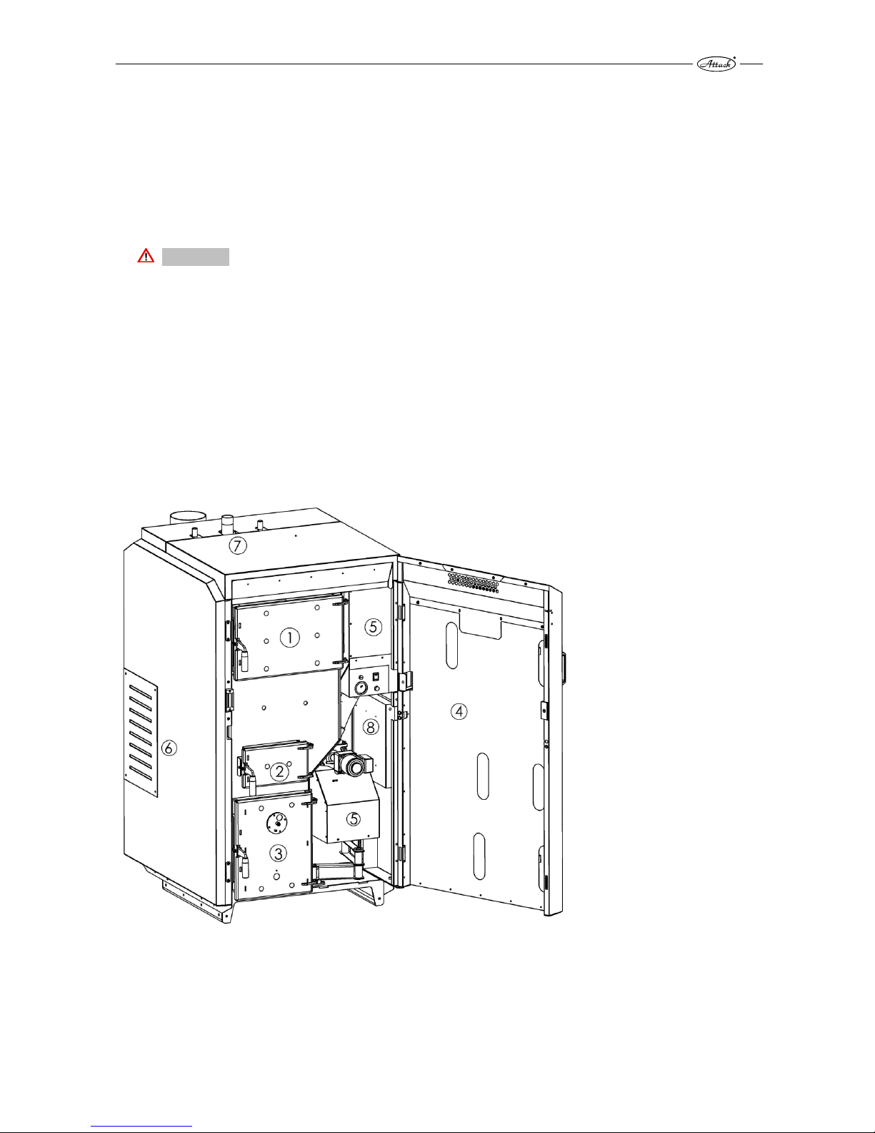
Pic. 1 Basic description of the boiler
1 –wood feeding chamber door, 2 –middle door for ignition and cleaning, 3 –combustion
chamber door with a sight-hole, 4 – main door, 5 – burner for pellet combustion, 6 – secondary
and primary air inlet for gasification, 7 – boiler flow connection, 8 – boiler control electronics.
Page 6
6
The boiler consists of the wood feeding and combustion chamber, pellet combustion chamber,
pellet burner, integrated pellet tank and heat exchanger. The boiler can be operated in either
wood mode or pellet mode, but not at the same time. The boiler is designed with reference to
the user comfort, i.e. to save time for heat-up, fuel cutting, cleaning and total time spent by the
boiler. The basic part of the boiler is a water cooled body, welded from boiler steel plate of 3–
6 mm to ensure long life time. The feeding chamber for gasification is equipped with a dry coat.
By elimination and moving the condensation point from the boiler body to the surface of the dry
coat is the boiler´s life extended. The dry coat can be easily exchanged, if it comes to its damage.
Turbulators in the tubular exchanger improve heat transfer into the heating water and ensure
automatic exchanger cleaning to maintain high efficiency during the operation and to extend
the boiler life. The boiler body is insulated with mineral wool. The covering is powder coated.
1.7 FUEL
1.7.1 WOOD
In the boiler ATTACK WOOD&PELLET it is possible to burn soft and hard chopped fuel wood with
the heat value 15–17 MJ/kg. Particularly suitable is beech, oak, fir, spruce, pine, poplar, alder,
willow, birch, ash, wych-hazel, locust, always within the humidity range of 12–20 %.
Recommended diameter of the wood logs is in the range of 80–150 mm. The maximum length
of wood logs is 580 mm and it must not be exceeded, otherwise they would get stuck in the
feeding chamber.
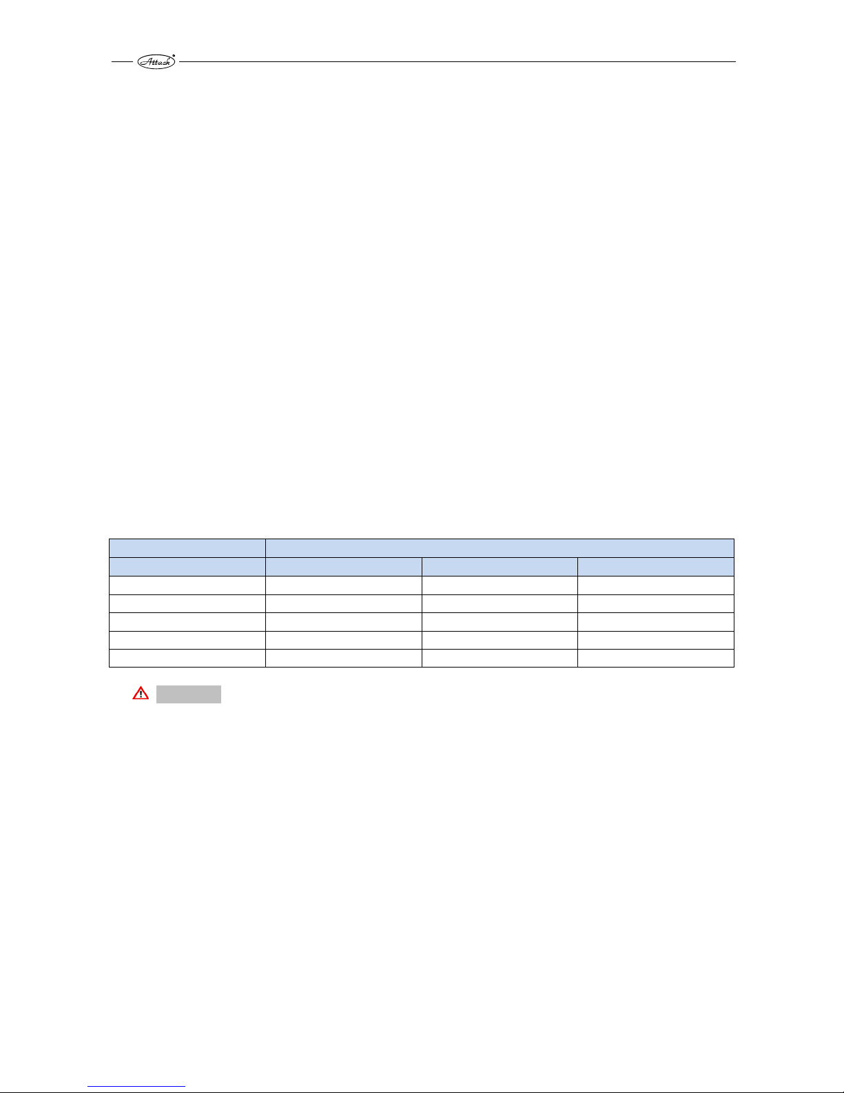
The heat value of the particular wood types:
Units
Wood Kcal/kg
MJ/kg
kWh/kg
Spruce 3 900 16,25 4,5
Pine 3 800 15,80 4,4
Birch 3 750 15,50 4,3
Oak 3 600 15,10 4,2
Beech 3 450 14,40 4,0
CAUTION
Wrong humidity or size of the wood may cause increase or decrease of output, low or high flue
gas temperature, excessive condensation, flame loss during the gasification process or
uncontrollable combustion.
Recommended storing and drying the wood:
Hard wood: 2 years in dry environment
Soft wood: 1 year in dry environment
When storing (drying) the wood, it has to be protected against rain. To dry the wood more
efficiently, stack to keep as large air gaps as possible. The wood will season faster with airflow
over the wood. If possible, store the wood for at least 1 day at a warm place (e.g. boiler room)
before loading it into the boiler (as it is warm, the efficiency of burning is increased).
Page 7

7
1.7.2 PELLETS
The pressed wood pellets wihout any additional materials can be burned in the boiler.
Parameters of the pellets should be following:
Approved pellet specification:
Measured weight: 600–750 kg/m3
Heat value: 4,7–5,0 kWh/kg
Size/diameter: 6 mm
Size/length: Caution! Max. 35 mm
Humidity – max.: 12 %
Ash content: 0,5–1 %
Content of crumble (dust:) max. 3 %
Ash melting temperature: min. 1 100°C
Norms : DIN 51 731 – HP 5, DIN Plus, or EN 14961-2 – A1
1.7.3 ALTERNATIVE FUELS
It is possible to use the wood briquettes made from pressed wood sawdust without any
additional adhesives or bidning materials.The briquettes must be always mixed in
the appropriate ratio to the wood (dependent on the size and shape of the briquettes) and must
not stuck in the refractory nozzle for wood gasification.
CAUTION
Use of unsuitable fuel types causes higher cleaning requirements and accumulation of an
agressive sediments and condensation that may lead to reduced functionality, damage to the
boiler and invalidate the warranty. Burning the wrong fuels may cause incorrect and
uncontrollable combustion.
Page 8
8
2. BOILER ASSEMBLY AND INSTALLATION
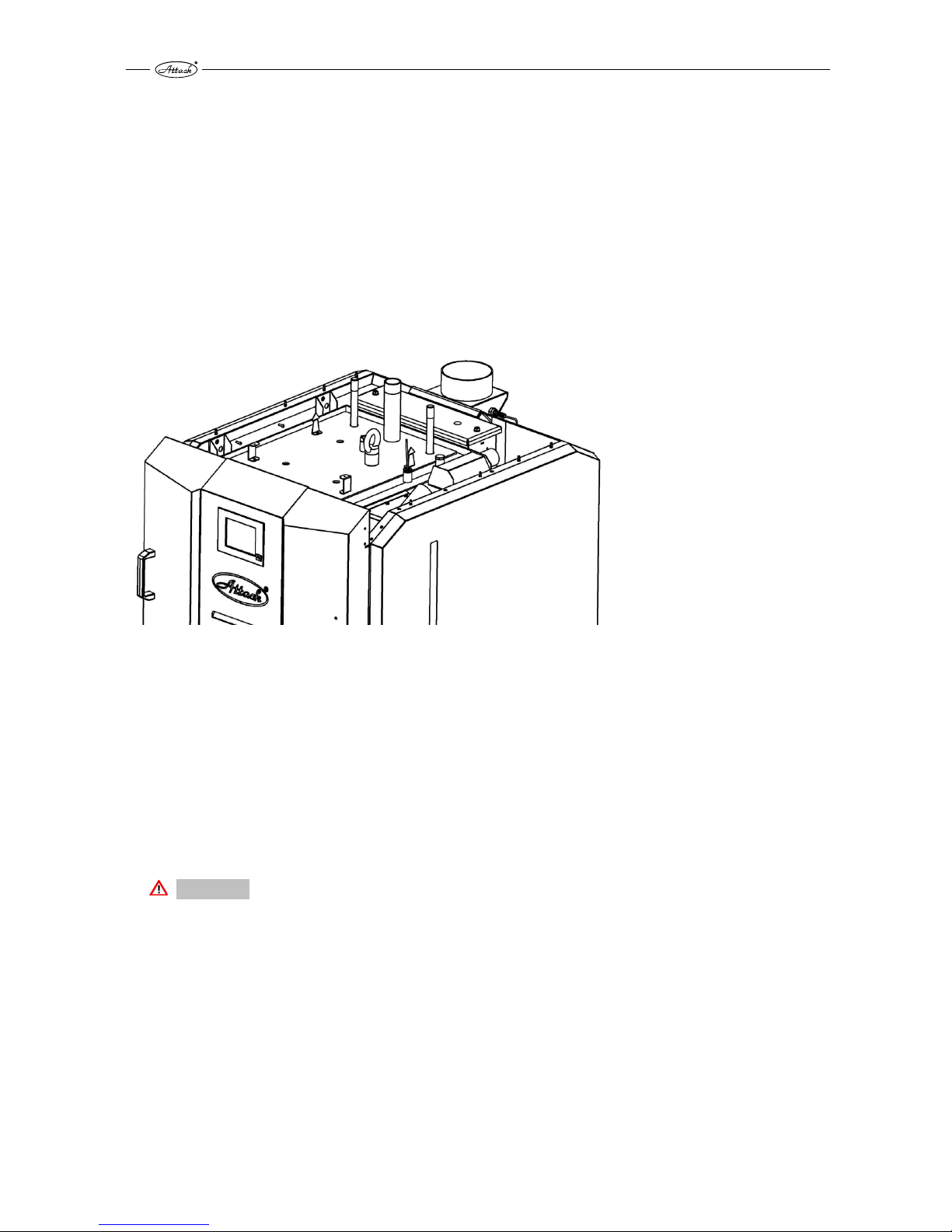
2.1 HANDLING THE BOILER
The boiler is delivered on a pallet. Handle it always on the pallet and put it down from the pallet
only at the point of installation. This can be done by a manipulation trolley or a crane and lifting
eye that is not included into the delivery (recommended specification: lifting screw with an eye
M20 ISO 3266, or M20 DIN 580). The lifting eye can be screwed into the chassis welded on the
upper cover of the boiler to hang the boiler. Carrying capacity of the hanging eye M20 is 1 200
kg, weight of the boiler is approximately 860 kg. Remove the upper boiler cover before hanging
the boiler on the hanging eye.
Pic. 2 Handling the boiler with the hanging screw with eye
2.2 GENERAL CONDITIONS OF INSTALLATION
The boiler can only be installed by a properly certified installer with valid certification to install
and assemble the heating appliances. Before installation, there must be a project made
following to the valid prescriptions. Before installation of the boiler, the worker must check
accordance of the data on the data plate with the data given in the project and documentation
of the boiler. Connection of the boiler must be done in conformity to the valid directives, norms,
ordinances and this instruction manual.
CAUTION
The producer takes no responsibility for damage caused by incorrect connection or
incorrect operation.
Page 9

9
BINDING NORMS FOR PROJECTING AND INSTALLATION OF THE BOILERS
Installation of the boiler must be done in conformity with the following norms:
STN EN 303-5 Heating boilers for solid fuels
STN 92 0300 Fire safety of the local appliances and heat sources
STN EN 60 335.1 +A11 Safety of the electrical appliances for household
STN 06 10 00 Local appliances for solid, liquid and gaseous fuels
STN 06 03 10 Central heating, projecting and installation
STN 06 08 30 Safety devices for central heating and D.H.W. preparation
STN 07 74 01 Water and steam for thermal energetic devices with
operation pressure of steam up to 8 MPa
STN 332000 4-46 Electrical installations of buildings – part 4: Ensuring safety
STN 332000–3 Electrical installations of buildings – part 3: Definition of the
basic characteristics
STN EN ISO 11202 Acoustics. Noise generated by machines and devices.
Definition of the emissions levels of the acoustic pressure at
a workplace and other precisely defined places by using the
approximative corrections in environment. (ISO 11202: 2010)
STN EN ISO 12100 Safety of machines. General principles of construction of
machines. Consideration and elimination of the risk (ISO
12100: 2010)
STN EN 953+A1 Safety of machines. Protection covers. General requirements
for design and construction of fixed and movable covers.
STN ISO 27574-2 Acoustics. Statistical methods for definition and verification
of the determined values of the noise emission of machines
and devices. Part 4: Methods for series of machines.
STN ISO 1819 Devices for fluent cargo transport. Safety prescriptions.
General clauses.
STN EN ISO 15614-1 Requirements for quality of the fusion welding of metal
materials
STN EN 287-1 Welding of reserved technical devices
STN 07 0240 Low pressure boilers, technical prescriptions
STN 07 0245 Warm water boiler with the output up to 50 kW. Technical
requirements, testing
STN 07 7401 Water and steam for heat energy devices with the steam
operating overpressure up to 8 MPa.
STN 73 4210 Manufacturing the chimneys and flue ways and connection
of devices
STN 92 0300:1997 Minimum distance of the external surface of the appliance or
flue way from the building constructions
Page 10

10
2.3 PLACING THE BOILER
The boiler is intended for installation and operation in an area conforming to (AA5/AB5) under
the STN 33 2000-3.
The boiler room must fulfill the above mentioned and the following requirements:
There can be no potentionally explosive environment in the boiler room, as the boiler is not
suitable for usage in such environments.
The temperature in the boiler room must not drop below freezing
Boiler itself does not provide any lighting. The user must ensure sufficient source of light,
according to the local norms and directives.
If the boiler is going to be installed above an altitude of 1 800 m, the installation has to be
consulted with the manufacturer
There must be an opening of at least 200 cm
2
in the boiler room for sufficient ventilation and
supply of the required amount of the air for combustion. The external environment should
not influence the functionality of the opening (rain, snow, wind).
When installing the boiler, it is necessary to keep a safe distance of its surface from
flammable materials, according to the degree of flammability:
from materials of flammability B, C1 a C2 200 mm
from materials of flammability C3 400 mm
from materials with the grade of flammability not approved under the STN 73 0853
400 mm
Examples of classification of the building materials by their degree of flammability:
degree of flammability A inflammable (bricks, blocks, ceramic tiles, mortar, parging)
degree of flammability B partly flammable (heraklith, lignos, board from basalt felt, novodur)
degree of flammability C1 difficult to ignite (hardwood (oak, beech), plywood, werzalit,
hardened paper)
degree of flammability C2 normal combustibility (softwood (pine, spruce), chipboard,
solodur)
degree of flammability C3 easily ignited (wood fibre boards, polyurethane, PVC, foam rubber,
polystyrene)
The sealing board or protection covering on the protected items must exceed the boiler edge
for at least 300 mm. Also other items from flammable materials must be protected in this way, if
they are placed near the boiler and it is not possible to keep the safe distance.
If the boiler stands on a flammable surface, it must be protected by an inflammable, heat
insulating mat, which exceeds the edge on the side of the feeding door and the ash tray door for
at least 100 mm. All materials of the A flammability degree can be used as an inflammable, heat
insulating mat.
The boiler must be placed in a such way ensuring sufficient space of at least 1 m from the front
and 0,5 m from the left (right) and rear side. It is necessary to leave the space of at least 1 m
above the boiler.
Page 11

11
This space is necessary for basic operation, maintenance and eventual service of the boiler. It is
not allowed to place the boiler in dwelling premises (including corridors).
CAUTION
The items from flammable materials must not be laid on the boiler and within the minimum
distance specified for material type, the permitted (safe) one.
The boiler must be turned off, if there is a danger of fire or explosion due to flammable gases
from paints or materials in the vicinity (e.g. work with painting materials, glues, etc.).
It is not allowed to place the boiler in dwelling premises (including corridors)!
2.4 BOILER CONNECTION TO THE HEATING SYSTEM
The ATTACK WOOD&PELLET must be installed in the system that fulfils the requirements for
quality of the heating water:
Slovak republic: STN 07 7401:1991
Austria: ONORM H5195-1
Germany: VDI 2035
Switzerland: SWKI 97-1
Italy: D.P.R. no. 412
To fill or re-fill the water in the system it is possible to use only the water treated to the values
under the STN 07 7401: 1992. The water must be pure, colourless, without suspendous
substances, oils, nor chemically aggressive ingredients. The water cannot be acidic (pH must be
higher than 7,2).
Callosity of the water must not exceed 1mmol/l and concentration of the Ca²Ѐ must be lower
than 0,3 mmol/l.
CAUTION
If the above mentioned conditions are not adhered to, then the warranty provided by the
manufacturer is void!
Use of antifreeze mixtures
It is not recommended to use antifreeze mixtures as their properties that are not suitable for
operation of the boiler. This particularly concerns decreased heat transfer, large thermal
expansion, ageing, damage of the rubber parts. When it is necessary, it is possible to use the
antifreeze mixture Alicol Termo (producer: Slovnaft Bratislava) – following experience of the
producer there will not come to the decreased safety of usage, nor to the significant influence
on the boiler operation. If this way of protection against freeze is not possible under the
particular conditions and the different antifreeze mixture is used, the warranty does not relate to
the wrong functionality, nor to the eventual faults of the boiler.
Page 12
12
2.4.1 PROTECTION AGAINST CORROSION
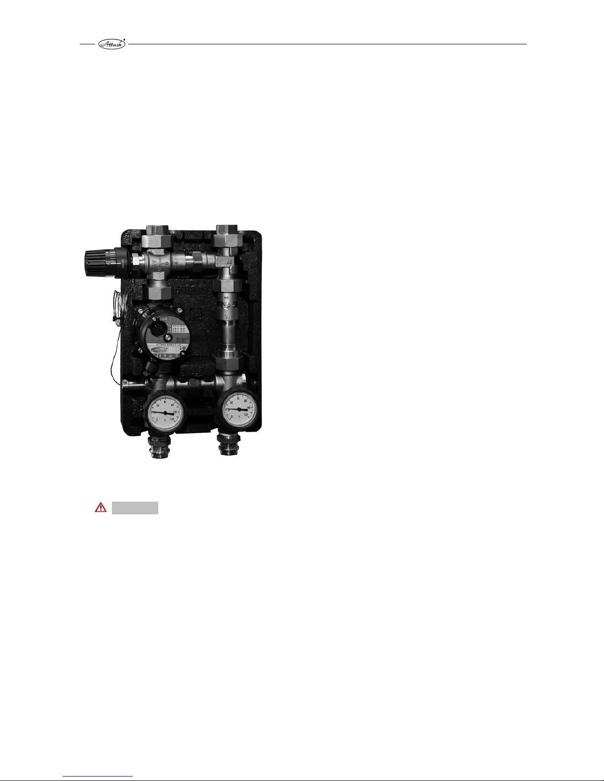
The boiler must be connected with a device regulating the temperature of the boiler´s return
connection. It is suitable to use the mixing device Attack-Oventrop (Pic.3), which enables
creation of the separate boiler and heating circuit. Thereby is the boiler protected against
undercooling and the creation of water steam. Acids and tars in the boiler´s feeding chamber are
eliminated.
The Attack-Oventrop device keeps the constant temperature of the return heating water flowing
into the boiler over 65 °C by setting the thermostatic head to the level 5–6.When the individual
thermal regulation mixing valve is used, it is possible to control the temperature of the heating
water independently on the temperature of water in the boiler by setting the flap. The
temperature in the boiler has to be kept in the range of 80–90 °C.
Pic. 3 Device ATTACK Oventrop
CAUTION
If a protection device against corrosion is not intalled in the system or the device does not work
properly, it may lead to creation of an aggressive condensate and thereby boiler damage.
Protection against condensation must be used during boiler operation, otherwise the
warranty is void!
Page 13

13
2.4.2 CHIMNEY
Connection of the appliance to the chimney hole must be always done with in line with local
regulations and the appropriate chimney association. The chimney must generate sufficient
draught and take the flue gas out into the atmosphere under all operating conditions.
Correct dimensions of the chimney are important for correct boiler function, because the
burning, output and boiler life-time are influenced by the draught. The chimney draught directly
depends on its diameter, height and surface finish of the internal wall. It is not allowed to
connect any other appliance to the chimney, where the boiler is connected. Diameter of the
chimney must not be smaller than the connection part on the boiler. The chimney draught must
achieve the precribed values, but it cannot be too high, not to decrease the boiler output and
interrupt the burning (flame). If there is too strong draught, install the throttle flap into the
chimney hole between the boiler and the chimney.
Minimum dimensions of the chimneys:
20×20cm min. height 7 m
20 cm min. height 8 m
15×15 cm min. height 11 m
16 cm min. height 12 m
The exact chimney dimension is defined by the STN 73 42 10. The prescribed chimney draught is
given in the Technical parameters.
2.4.3 FLUE GAS CONNECTION OF THE BOILER
The flue connection must lead into the chimney hole. If it is not possible to connect the boiler to
the chimney hole directly, then the appropriate extension should be as short as possible, of up
to 1 m length, without any additional heating area and it should ascend in direction to the
chimney. It is suitable to insulate the flue connection to achieve the sufficient flue gas
temperature and to prevent the condensation in the chimney. The flue connection must be
mechanically tight (it should be mounted to the boiler and tightly fixed by screws) and tight
against the flue leakage. There must be possibility of the internal cleaning. The flue connections
must to lead through the foreign dwelling or commercial premisses. The internal diameter of the
flue connection must not taper in direction to the chimney. It is not suitable to use the elbow
connectors. There must be a „T“connection of the flue outlet to the chimney, to ensure that the
condensate must leak into the appropriate tray and not into the boiler.
The flue connection must comply with local regulations and only be conducted by authorised
and trained personel.
2.4.4 CONNECTION TO THE ELECTRICITY MAINS
The boiler is connected to the electricity mains of 230V/ 50Hz/16A by an electrical cord with
plug. In the case of need, the power supply cord of the M type must be replaced with an
adequate one by the service organization.
The appliance must be placed in such a way that enables the user to reach the connection plug.
The boiler must be connected to the 16A socket circuit by a circuit breaker (following the STN EN
60 335-1 + A11:1997).
Page 14
14
2.4.5 CONNECTION OF THE EXTERNAL PELLET TANK
The boiler is equipped by a motor for vacuum pellet feeding from an external tank. The external
tank can be placed nearby the boiler or in another room. The max. length of the suction tube is
10 m. The tank can be in the higher position, but not in the lower position than the boiler. It is
recommended to use the ATTACK vacuum tanks for the ATTACK WOOD&PELLET boiler. The
suction tubes ( 50 mm) and the vacuum tank can be ordered as accessories together with the
boiler.
Connection of the suction and blow out tube marked on the rear side boiler as „PELLET IN“and
„PELLET OUT“.
2.4.6 LEFT DOOR VERSION
There is an option of the ATTACK WOOD&PELLET boiler with the left door (door hinges on the
left side). It can be done before the boiler start-up or later, when the boiler is not in service. The
main, upper, middle and bottom door can be turned without need of the any additional tools.
Everything necessary is contained in the boiler. Use the standard tools: cross screwdriver, fork
key of 8–13 mm or nut, allan key of 6 mm, etc. The adjustment has to be done by a trained
worker.
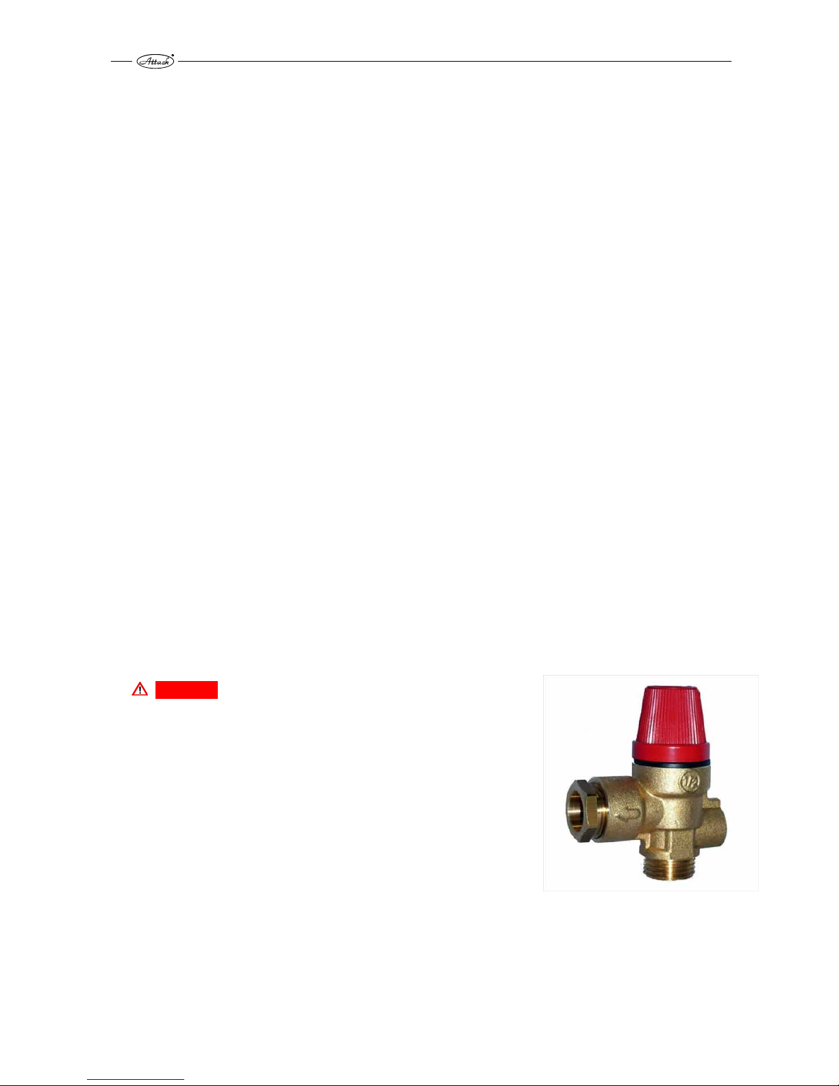
2.4.7 CHOICE AND WAY OF CONNECTION OF THE CONTROL AND SAFETY
ELEMENTS
The boiler is delivered with the basic regulation and control equipment. This equipment must be
completed with other items (not delivered with the boiler) in line with local regulations, that
have to be installed in the heating circuit – particularly the following ones: safety valve (Pic. 4)
against exceeding the permitted pressure in the heating system (prescribed value: 2,5 bar), valve
of the boiler aftercooling loop to take the excessive heat from the boiler into the waste and
deaeration valve for the correct boiler function. The volume of the expanse vessel in the system
has to be defined by a designer of the heating system according to the system design and local
regulations. The electrical installation related to the additional boiler equipment has to be done
by a specialist and following the valid regulations.
DANGER
The heating system must be equipped with a safety valve against
exceeding the pressure in the boiler (2,5 bar). This valve should
be placed on the flow connection of the boiler, always installed in
front of the boiler closing valve (or in front of the Oventrop –
scheme 1). If the safety valve is not functional, the excessive
pressure will not be eliminated and it may cause an explosion
of the boiler.
Pic. 4 Safety valve against the overpressure
Page 15
15
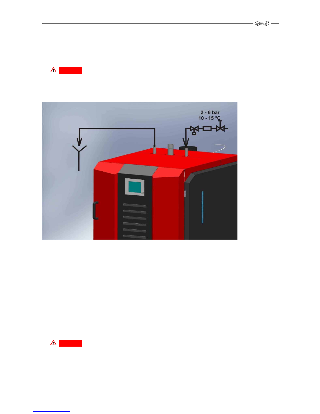
Boiler protection against overheating
Every wood gasifying boiler must be fitted with a functional aftercooling circuit. The appropriate
valve ensuring this function can be ordered as an accessory. On the pic. 5 you can see the correct
installation of the valve of the aftercooling circuit.
DANGER
Following the norm EN303-5, the aftercooling circuit against overhetaing must not be
used for other purpose than the boiler protection against overheating.
Pic. 5 Connection of the thermostatic valve to the aftercooling loop
The valve must be permanently opened at the cold water inlet into the boiler aftercooling
circuit. The aftercooling circuit must be connected to the functional distribution of the cooling
water (e.g. to the distribution of the cold water in the water supply network) with the
temperature of 10–15 °C and operating overpressure of 2–6 bar, ensuring the safe operation
even by a power failure.
The thermostatic valve at the outlet of the aftercooling circuit with the sensor placed in the rear
side of the boiler protects the boiler in the following way. If temperature of the water in the
boiler exceeds 95 °C, the valve fills the aftercooling circuit with the water from the water supply
network to absorb the excessive heat. For the case that the boiler gets overheated and the
thermostatic valve is open, it is necessary to ensure the permanent outtake of the warm water
from the aftercooling circuit into the waste. Functionality of the aftercooling circuit and the
thermostatic valve can be checked manually, by the manual button of the thermostatic valve.
DANGER
If the circulation of the cooling water through the aftercooling circuit is not ensured, when
the thermostatic valve is open, there is a danger of the boiler damage! The warranty is not
valid in such a case.
Page 16

16
2.4.8 CONNECTION TO THE ACCUMULATION TANKS
The accumulation tanks are connected to be warmed and the accumulated heat is continually
used according to the requirements of the heated space. When the boiler operates at full output,
the accumulation tanks are heated to 80–90 °C. Usage of the accumulation tanks together with
the boiler ATTACK WOOD&PELLET brings several advantages. The main advantages are:
prolonged life of the boiler, cleaner operation, minimal creation of acids and condensate, smaller
frequency of the fuel loading, lower probability of the boiler overheating and fuel saving.
The recommended volume of the accumulation tank for the boiler ATTACK WOOD&PELLET 25 is
2.000 l (the min. volume is 1.250 l). By full load of the hardwood (i.e. 6 hours of operation at full
output of 25 kW), the boiler produces 150 kWh of energy. This is adequate to the loading of the
2.000 l accumulation tank from 20 °C to 80 °C, if there is no other energy consumption. Thereby
it is necessary to consider the boiler usage and operation as well, when you are choosing the
accumulation tank: by the accumulation tank of 2.000 l it is necessary to load the full chamber,
by 1.000 l there is half of the chamber to be loaded (if there is no energy outtake from the tank).
Example 1:
The external temperature of environment is -5 °C and the heat loss of the building is 10 kW. The
boiler output by full operation is 25 kW. There is an accumulation tank of 1.250 l, that is
discharged (its upper and bottom temperature is 20 °C). As the heating system (to cover the heat
loss) takes 10 kW from the accumulation tank and the boiler has the output of 25 kW, the
accumulation tank is heated by the remaining 15 kW. The output of 15 kW, by the full load of
hard wood and during the 6 hours of operation, creates the energy of 90 kWh. This energy heats
the accumulation tank from 20 °C to 62 °C despite of the fact, that the 10 kW are being taken.
This is a safe and economical operation, when the heat is not taken into the waste (the boiler
was cooled down by the aftercooling circuit). The boiler is able to cover the heat loss for 15
hours just by a single load of the wood.
Example 2:
The external temperature of the environment is +3 °C and the heat loss of the object by this
temperature is 5 kW. The boiler output at full operation is 25 kW. There is an accumulation tank
of 1.250 l, that is discharged (its upper and bottom temperature is 20 °C). As the heating system
(to cover the heat loss) takes 5 kW from the accumulation tank and the boiler has the output of
25 kW, the accumulation tank is heated by the remaining 20 kW. The output of 20 kW, by the full
load of hard wood and during the 6 hours of operation, creates the energy of 90 kWh. This
energy heats the accumulation tank from 20 °C to 82 °C despite of the fact, that the 10 kW are
being taken. This is a safe and economical operation, when the heat is not taken into the waste,
but if the heat loss was smaller, the boiler could get overheated, because it would not be cooled
down. In such case it would come to activation of the aftercooling circuit and the excessing heat
would be taken into the waste. In case of the constant heat loss of the object (5 kW), the charged
accumulation tank would cover the heat loss approximately for the next 24 h. It means that by
a single load of wood and under the above mentioned conditions it would be possible to cover
the heat loss of the building for 30 hours.
Thereby it is very important to load just the amount of wood, adequate for heating the
accumulation tank and not to overheat it, because the excessive heat would be taken into the
waste unused. Such operation would not be economical and the safety element, the
aftercooling circuit would have to be activated.
The bigger volume of the accumulation tank decreases the risk of overheating and the
frequency of loading the wood.
Page 17

17
Note:
The above mentioned fact is relevant by the operation with WOOD.
By the operation with PELLETS it is not relevant, as the boiler does not have to be
connected to the accumulation tank, if ONLY PELLETS would be used.
Standardly delivered accumulation tanks ATTACK*
AK AS HR HRS
TUV
TUVS S SS
300 300 — —
300
300 — —
400 400 — —
400
400 — —
500 500 600 600
500
500 500 500
800 800 800 800
600
600 800 800
1000 1000 1000 1000
800
800 1000 1000
1500 1500 1250 1250
1000
1000 1250 1250
2000 2000 1500 1500
1250
1250 1500 1500
2500 2500 2000 2000
1500
1500 2000 2000
3000 3000 — —
2000
2000 — —
4000 4000 — — — — — —
5000 5000 — — — — — —
AK – standard accumulation tank intended for the accumulation of energy of the heating water
AS –standard accumulation tank intended for the accumulation of energy of the heating water,
equipped with a coil for connection of the solar panels
HR – combined accumulation tank for accumulation of energy of the heating water and the
domestic hot water preparation
HRS – combined accumulation tank for accumulation of energy of the heating water and the
domestic hot water preparation, equipped with a coil for connection of the solar panels
* The volume necessary for the accumulation of energy can be covered by one or by several
accumulation tanks. The accumulation tanks can be connected together to create the sufficient
volume of water for accumulation. Thereby, if you decide for a volume of 2.000 l, it is possible to
use one tank of 2.000 l or two tanks of 1.000 l connected together. The required way of
connection is given in the chapter „Recommended hydraulic schemes of boiler connection“.
Page 18
18
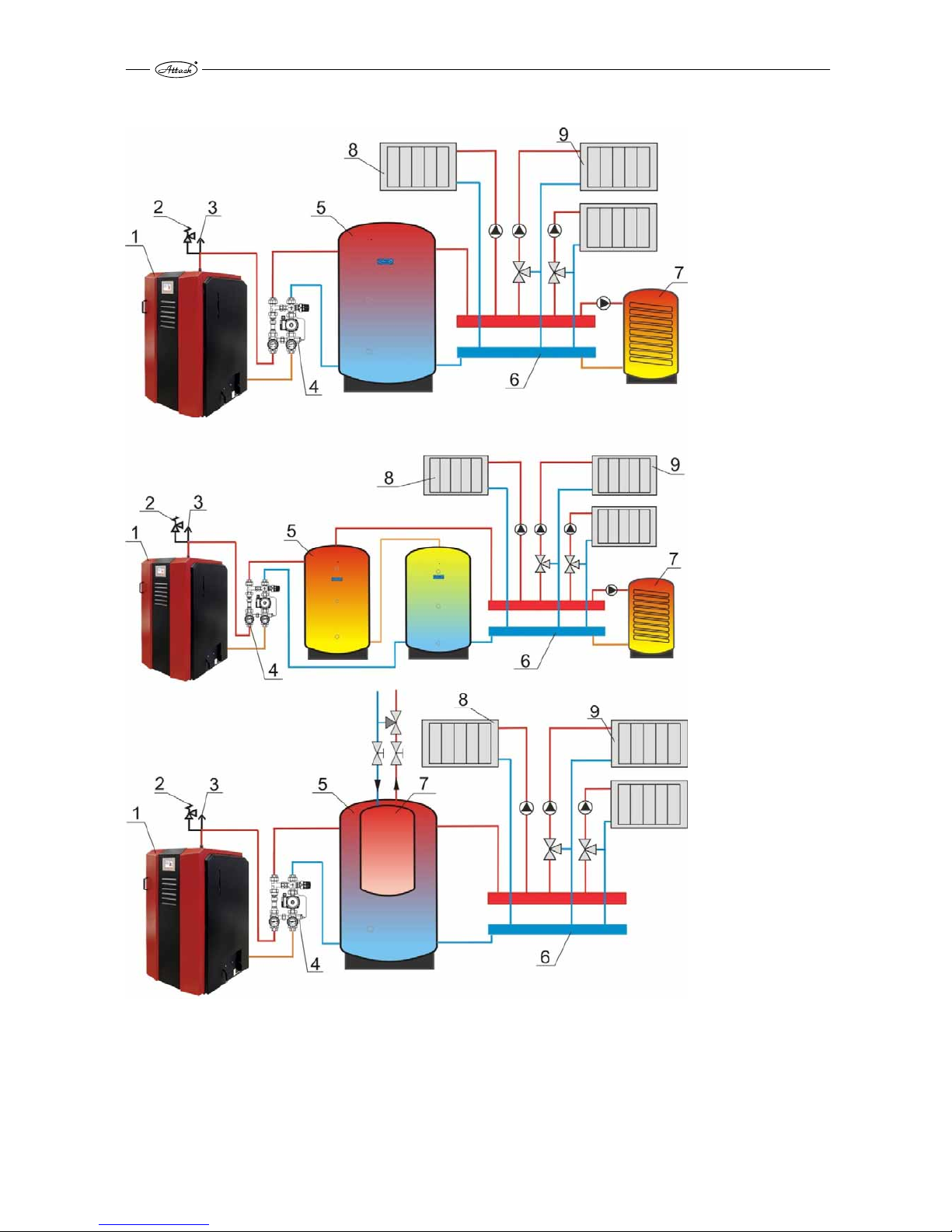
2.4.9 RECOMMENDED HYDRAULIC SCHEMES OF BOILER CONNECTION
Pic. 6. Hydraulic connection of the boiler into the heating system
1 – boiler, 2 – safety valve, 3 – deaeration valve, 4 – Attack Oventrop, 5 – accumulation tank
Attack AK or HR, 6 – distributor, 7 – tank for domestic hot water, 8 – direct heating circuit, 9 –
mixing heating circuit
Page 19

19
3. BOILER START-UP
Boiler preparation for operation
The boiler must be assembled, installed and started-up only by an installer certified for the
installation of the heating appliances. Before starting the boiler, it is necessary to check, if the
hydraulic system is filled with water by the correct pressure, deaerated and without decreasing
pressure of the heating water. Check tightness and strength of the flue construction and
functionality of the aftercooling circuit by pressing the valve manually. The boiler must be
operated in conformity with the instructions given in this manual to achieve the quality function.
CAUTION
There may come be condensation and condensate leakage by the first firing of the boiler. This
will disappear after the the first burn. It is a natural effect.
WARNING
It is necessary to be more careful, if the boiler was out of order for a longer period (in summer or
in case of failure). The pump could get blocked (and the boiler could get overheated and the
aftercooling circuit would be started), or the water could leak out of the system. Check the
correct pump function and the pressure of water in the heating system!
See the chapter „BOILER CONTROL“about putting the boiler into operation (heating up, loading,
filling the tank with pellets, etc.).
4. WARRANTY CONDITIONS
The warranty for the boiler is valid only if the boiler installation was done by a person certified
under the valid norms and following the instruction manual. The company who performed the
installation must completely and clearly fill the form. If the boiler is damaged by an inexpert
installation, the company who installed it has to carry the costs for repair, only use approved and
properly trained installers.
The user has to respect the instructions for operation and maintenance given in the manual. If
the instructions for operation and maintenance are not kept, the use of the boiler is
unauthorised and careless or incorrect fuel is used, the warranty is not valid and the customer
has to carry the costs by damage.
The warranty is valid only in the case, that the boiler was installed and operated in the
following way:
together with device for the boiler protection against condensation ATTACK-OVENTROP
with prescribed fuel given in the chapter „FUEL“
with the thermostatic valve installed against the boiler overheating
with the chimney of appropriate parameters (diameter, height) given in the chapter
„CHIMNEY“
the boiler was regularly and sufficiently cleaned as it is given in the chapter „CLEANING“
the boiler was operated following the instructions given in this manual and not in the
different way.
The warranty is valid for a complete boiler ATTACK WOOD&PELLET, except of wearing boiler
parts that are usually worn, and therefore they cannot be included into the warranty:
glass sealing cords of the door and ash tray.
refractory nozzle
Page 20

20
5. TECHNICAL PARAMETERS
Parameter Units AWP 25
Nominal output by wood kW 25
Nominal output by pellets kW 30
Range of the output by wood kW 12,5 ÷ 25
Range of the output by pellets kW 9 ÷ 30
Heat-exchange area m² 2,18
Volume of the feeding chamber l 160
Volume of the integrated pellet tank l 48
Dimension of the feeding door mm 230×445
Prescribed chimney draught Pa 23
Max. operation overpressure of water kPa 250
Pressure loss of water (T 10 K)
kPa 2,1
Pressure loss of water (T 20 K)
kPa 0,6
Boiler weight kg 860
Diameter of the flue outlet mm 150
Boiler height "A" mm 1620
Boiler width "B" mm 940
Boiler depth "C" mm 1220
Length of the feeding chamber "D" mm 580
Diameter of the flow connection " G 6/4"
Diameter of the return connection " G 6/4"
Grade of protection IP 21
El. input by a nominal output W 90
El. input by a minimal output W 32
El. input in the standby mode W < 15
Efficiency of the wood boiler % 90,5
Efficiency of the pellet boiler % 90,4
Boiler class EN 303-5:2012 — 5
Flue gas temperature by the nominal output by wood °C 156
Flue gas temperature by the min. output by wood °C 92
Flue gas temperature by the nominal output by pellets °C 130
Flue gas temperature by the min. output by pellets °C 86
Flue gas flow by nominal output kg/s 0,019
Flue gas flow by min. output kg/s 0,005
Max. noise level dB 65
Wood consumption by nominal output kg/h 7,2
Pellet consumption by nominal output kg/h 6,8
Max. length of wood logs mm 560
Time of operation by max output by wood h 6
Volume of water in the boiler l 126
Min. volume of accumulation tank l 1250
Connection voltage V/Hz/A 230/50/16
The producer, ATTACK, s.r.o. reserves right of technical changes of the products without any previous
announcement!
Page 21

21
Pic. 7 Description of particular boiler parts
1 – boiler body, 2 – main door, 3 – cover of the air inlets into the wood gasifying section, 4 –
display cooling, 5 – touch display, 6 – cover of electronics, 7 – flow connection, 8 – aftercooling
circuit, 9 – cover of turbulators, 10 – lambda probe, 11 – flue connection, 12 – exhaust fan, 13 –
return connection
426
312
G 6/4"
G 1/2" G1/2"
1
2
5
9
1
0
0
50
50
1
6
4
1
6
0
4
1
6
4
G
6
/
4
"
1
5
0
8
611
776
1125
150
1
6
0
4
568
904
951
3
0
0
1207
13
12
11
7
8
9
10
1
2
4
5
6
7
8
5.1 DIMENSIONS OF THE BOILER
ATTACK WOOD&PELLET 25
Page 22

22
6. REGULATION OF THE BOILER AND THE HEATING SYSTEM
6.1 IN GENERAL
DANGER
If you tun the main switch off during the boiler operation, it has no regulation. Then, any
dangerous states may cause the serious health or property damage. Always let the fuel
completely burn out and the boiler cool down before turning the main switch off!
WARNING
Opening the upper and middle door of the feeding chamber or the bottom door of the
combustion chamber during the operation may cause accumulation of the flammable gases and
their explosion, this may cause serious damage to health or property. It is forbidden to open
any door behind the main door during the operation!
CAUTION
6.2 EMERGENCY ACTIONS
Boiler overheating
If the boiler is in WOOD mode and it starts to overheat and the functionality of the aftercooling
loop fails from any reason, do the following:
Do not open any door of the boiler!
Turn the boiler off by the STOP button and confirm the red emergency message „I really
want to stop the boiler“
Start all the pumps, heating circuits, open all the 3-way valves (attention, the max.
temperature by the floor heating is 40 °C), to ensure the max. heat energy outtake from the
boiler
Leave the boiler room and close the door.
Open the thermostatic heads on all radiators (the heating season does not make
a difference), eventually let the domestic hot water flow - run hot water tap, if the boiler is
connected for the D.H.W. preparation as well
Contact your installer
DANGER
Never turn the main switch off, nor disconnect the boiler from the electricity mains, when
the boiler gets overheated!!
Page 23

23
6.3 PREPARATION FOR THE OPERATION, FILLING THE INTEGRATED
PELLET TANK
CAUTION
Check, that the hoses of the vacuum suction are connected correctly and airtight, before
starting the pellet suction into the integrated tank.
Before starting the operation of the boiler ATTACK WOOD&PELLET for pellets, it is necessary to
suck the pellets into the integrated tank manually. Use the TEST mode, by clicking on the
„vacuum suction“. Watch the level of the pellets sucked through the side control opening or in
the information menu of the PELLET SENSOR. The sufficient amount of pellets in the integrated
tank is visible through the full pellet indicator and by the green light of the PELLET SENSOR.
After this, the pellets will be sucked automatically. In the case of error you can always fill the tank
by the TEST mode.
6.4 DESCRIPTION OF THE SAFETY DEVICES
Description of the main regulation of the boiler (Pic. 8):
1. Emergency thermostat with reset – boiler protection against overheating (when the
temperature of 110 °C is exceeded, all the electrical devices in the boiler are disconnected,
except of the circulation pump; when the temperature of the water in the boiler decreases
under 85 °C, it is necessary to demount the cover and to manually press the thermostat
button.
2. Main fuse – boiler protection against the electrical short circuit
3. Main switch – start/stop of the boiler. Unplug the whole boiler from the electrical mains.
4. Combined thermo manometer. Actual information about the temperature and pressure,
independent of power supply.
Pic. 8 Description of the main regulation of the boiler
Page 24

24
6.5 BOILER CONTROL AND OPERATION
The combustion process in the boiler ATTACK WOOD&PELLET is controlled by the modern
electronics, equipped with software operating on the basis of the latest knowledge in the field of
the biomass burning. There is an advanced touch screen, displaying multiple information to
enable the quick identification of the state of the boiler and its parameters. On the pic. 9 there is
the basic data display.
Pic. 9 The basic data display
1 – boiler temperature, 2 – flue gas temperature, 3 – actual fan output, 4 – operation mode, 5 –
boiler state, 6 – state of regulation, 7 – records of errors and error messages, 8 – time remaining
until the cleaning starts (of the burner, of the exchanger), 9 – setting of parameters (basic,
service ones), 10 – general settings, 11 – information, 12 – indicator of the actual pellet level, 13 –
language, 14 – actual boiler output (relevant for wood and pellets)
The regulation of the WOOD burning is ensured by the Lambda probe together with the
controlled rotations of the exhaust fan, controlled inlet of the primary and the secondary air,
measuring the temperature of the boiler and flue gas.
The regulation of the PELLETS burning and feeding is ensured by the integrated vacuum feeder
(pellet suction from the main tank into the built-in integrated tank), sensor of the pellet
presence, turnstile auger, ignition coil, photocell, fan with controlled rotations and by the
automatic cleaning.
11
13
14
Page 25

25
6.5.1 DESCRIPTION OF THE MAIN CONTROL MODES
Pic. 10 The main control modes
The way of the boiler operation can be changed in dependence on the operation mode in
the following way (Pic.10):
HEATING OFF – select this mode, if the boiler is going to be unused for a longer period. It is
usually in summer, if the boiler is not used to prepare the domestic hot water. Then, the boiler
will be switched into the STANDBY mode.
TESTMODE – under this mode you can test the functionality of particular devices in the boiler
(fans, grate cleaning, coil, vacuum suction, turbulator cleaning, pump, etc.).
AUTOMATIC – under this mode is boiler working automatically and it is regulated by the boiler
temperature. Always, when the temperature decreases under the adjusted temperature
decreased by hysteresis, the boiler is started (if the boiler works under the mode WOOD, it will
not be started automatically, as it is possible only under the COMBI mode).
TIME – this mode determines the particular time intervals, when the boiler is going to work (this
is related only to the COMBI mode for the PELLET burning). The time mode does not influence
the boiler operation for WOOD, because the purpose of such operation is to keep the output of
100 % and to produce as much energy as possible to be stored in an accumulation tank.
PUFFER/BOILER – this mode serves to control the discharging of the accumulation tank. The
external module is required.
EXTERNAL START– this mode works under the room thermostat. If you connect the room
thermostat into the electronics and select this mode, then boiler in the COMBI mode, operating
for PELLETS, will work according to the requirement for heat from the room thermostat.
Page 26

26
6.5.2 DESCRIPTION OF THE CONTROL MODES, RELATION BETWEEN THE
MODE WOOD AND COMBI
The ATTACK WOOD&PELLET boiler belongs to the combined boilers indeed, without for user
interaction with the boiler after the wood is burned out, to start the pellet burning process. The
boiler automatically detects, that the wood is burned out and if there is a requirement for
heating, the pellet combustion is started.
The boiler can work under two control modes: the WOOD and the COMBI. The WOOD mode is
especially intended for the wood burning and the combined boiler works as the standard wood
gasifying boiler. After starting the WOOD mode, the boiler controls the wood combustion
process, which is stopped, when the wood burns out. In this mode is the accumulation tank
charged to use the heat during the next day and night, while the pellets are not being burned.
This mode is advantageous within the periods like autumn and spring, because the heat loss of
the building can be covered by the heat from the accumulation tank for a couple of hours or
days. The WOOD mode cannot be interrupted anytime – it is necessary to wait, until the wood
burns out. Then it is possible to get into the COMBI mode.
Under the COMBI mode you can select the fuel for the start of operation (WOOD or PELLETS). If
you select the WOOD operation, the boiler controls the process of wood gasification and the
process of pellet burning is started, when the wood burns out and there is a requirement for
heating.
Under the COMBI mode, the boiler starts the process of pellet burning and it works as a standard
pellet boiler. If the boiler currently burns pellets, this operation can be anytime interrupted (it
takes approximately 5 min, until the pellets are burned out) and the wood combustion can start.
As it is given above, the opposite process is not possible.
DANGER
Under the COMBI mode, when you are starting the operation with pellets, always check that
there is no wood or other fuel in the feeding chamber. Otherwise, you may cause the
uncontrolled burning and there is a risk of the serious injury or property damage.
6.5.3 OPERATION WITH WOOD
Use this mode, if:
You wish to operate the boiler as a WOOD gasifying boiler. When the WOOD is burned out in the
feeding chamber, the boiler is stopped (the pellet part will not be automatically started to work).
The ways to light the boiler up:
The manual mode of lighting up the wood is used, if the boiler was heating during the day
before or if there are cinders remained in the feeding chamber.
The automatic mode of lighting up the wood can be used after the boiler is cleaned and
there are no cinders to make it easier. The automatic mode of lighting up the wood needs
more electrical energy than the manual mode and it requires the sufficient amount of pellets
in the integrated tank.
Page 27

27
6.5.3.1 MANUAL LIGHT UP OF WOOD
1. Turn the main switch on, if it has not been done yet.
2. Open the main door and the door of the feeding chamber. Check the level of ash in the
feeding chamber. If it exceeds 50 mm, clean the feeding chamber – it is not necessary to
clean the feeding chamber every day, if the ash still contains the solid cinders. The cinders
that remain in the ash contain the usable energy and they enable faster lighting up the
wood. The feeding chamber is cleaned through the middle door by the fire hook (See the
chapter 14. Boiler cleaning).
3. Open the door of the feeding chamber and clean it. It is the best to use a fire hook and to
remove the ash ash in direction to you. Always clean the combustion chamber before
heating the boiler up!
CAUTION
If the combustion chamber is not cleaned properly, its volume is rapidly decreased and it may
cause imperfect burning and dangerous states. Never operate the boiler with the uncleaned
combustion chamber!
4. Put the paper or cardboard (the best material), rolled into tubes (Pic. 11). If there are cinders
on the bottom of the feeding chamber, put the paper or the cardboard on them.
Pic. 11 Preparation for lighting up the wood
5. Put the wood of a smaller diameter (chips of 20×20 mm) on the cardboard (pic. 12) to make
the process of lighting up faster and more stable. Put the casual wood on the fine wood in
the way enabling the free air flow. Try to use the feeding chamber in the best way to load as
much wood as possible. Load the full chamber (Pic. 13).
Page 28

28
Pic. 12 The way to prepare the wood for lighting up
Pic. 13 Loading the full chamber
6. Close the upper and the bottom door, manually light up through the middle door only.
7. Enter the WOOD mode via display and confirm it by click (Pic. 14).
Page 29

29
Pic. 14 Starting the WOOD mode.
8. After selecting the wood operation mode, activate the lighting up process by the START
button (Pic.15).
Pic. 15 Activation of the wood operation mode
Page 30

30
9. There are two options of lighting up under the WOOD operation mode (Pic. 16) – the manual
and the automatic way. Under this mode, select the manual ignition. The exhaust fan will
start to work and the boiler will be prepared for lighting up.
Pic. 16 Lighting up the wood in the wood gasification part:
1 – manual ignition (by wood chips, newspaper, cardboard or a liquid fire starter 2 – automatic
ignition, 3- period of lighting the wood up by the pellet part, 4 – delayed start, 5 – output of the
pellet burner, while the wood is being ignited
10. Light the paper or the cardboard through the middle door by a lighter (Pic. 17). Keep the
middle door partly open, until the cardboard and the wood chips light up (approximately for
5 min) and the chimney gets the draught. Afterwards, close the door. This way of heating is
very quick and it enables to heat the boiler up without any smoke. Through the pivot control
opening on the bottom door you can watch the flame created by the process of gasification.
Close the main door after verifying, that the flame was created and the boiler correctly
gasifies.
Pic. 17 Manual light-up of the wood
Page 31
31
6.5.3.2 AUTOMATIC LIGHT-UP OF WOOD
The wood can be automatically ignited by pellets, with no need to prepare the lighting-up with
paper, nor cardboard. However, it is necessary to use the wood of small diameter (wood chips of
20×20 mm).
CAUTION
The automatic light-up of the wood is a complicated process and the first trial requires the
attention of the customer. It is necessary to select the parameters of the automatic light-up
carefully, to avoid the uncontrolled wood burning in the feeding chamber of the boiler. Do not
use the automatic light-up of wood, if the parameters of your chimney do not achieve the
values given in this manual. The problems with the automatic wood ignition may occur due to
the cold chimney or in summer, when there is a chimney draught naturally decreased. Thereby it
is necessary to consider the automatic wood ignition carefully in summer and by the cold
chimney.
Procedure of starting up the automatic wood ignition:
1. Repeat the procedure under the 6.5.2.1, points 1–3.
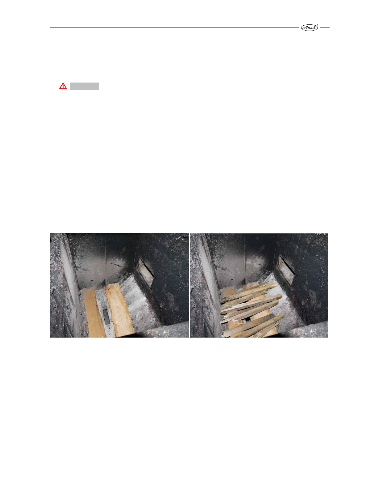
2. Put the wood of small diameter (wood chips of 20×20 mm) on the bottom of the chamber to
make the process of heating-up faster and more stable. Put the ordinary wood on the fine
wood in the way enabling the free air flow. In the ¼ of height should be the wood laid crosswise to make a tunel to light the wood up from the pellet part (Pic. 18). Try to use the loading
chamber in the best way to feed as much wood as possible. Load the full chamber.
Pic. 18 Loading the wood into the chamber by the automatic light –up
3. Close all door (upper, middle, bottom, main ones).
7. Use display to enter into the WOOD mode following the chapter 6.5.2.1, point 7 and 8.
8. After the “start options” are displayed, select the parameters to start the automatic WOOD
light up (Pic. 19). The “starting time” defines how long the flame from the pellet part will be
igniting the wood. The “start in” defines the time delay of start. Here you can set, that the
boiler will not start the automatic light up immediately, but with a time delay given as the
“start in” parameter. The value of the output for the wood ignition by the pellet part must be
considered carefully. Too high output may cause an inappropriate emission of the gas
substances from wood and to leak of the smoke from the loading chamber into the primary
air of the boiler. Thereby we recommend to try the automatic wood light up by the lower
output as first (approximately 30 %).
Page 32

32
Pic. 19 Parameters of the automatic wood light up
2 – start of the automatic wood light up, 3 – starting time, 4 – start in, 5 – output
Page 33

33
6.5.4 COMBINED OPERATION MODE
The combined operation mode is a fully automatic mode that is able to operate the WOOD
burning or the PELLET burning, but not both at the same time.
DANGER
The combined mode serves for operation with either of the fuel types – the WOOD or the
PELLETS. Never try to burn WOOD and PELLETS at once, because it may cause uncontrolled
burning, a health hazard or property damage.
Use this mode, if:
1. You are going to load the full loading chamber with wood and you wish to cover the
requirement for heat with the pellet burning, after the wood burns out.
2. You wish to operate the boiler with PELLETS only.
Start the COMBI mode through the mode options (Pic. 20) by a double-click on the COMBI.
Pic. 20 Start of the COMBI mode
The combined mode can start with burning the wood or burning the pellets. It is not possible to
burn both fuels (i.e. the wood and the pellets) at the same time.
Page 34

34
After selecting the COMBI mode it is necessary to choose the fuel that will be burned as first.
(Pic. 21).
Pic. 21 Selection of the fuel to start the COMBI mode
If the WOOD is in the loading chamber, the PELLET mode must not be started!
If the boiler was started with wood, pellets can be used after it burns out. The operation with
wood cannot be interrupted by the operation with pellets. The boiler struggles to burn all wood
before it starts to burn pellets. The operation with pellets can be anytime interrupted (the pellets
must automatically burn down in the burner) and the wood can be loaded and burned.
DANGER
It is very dangerous to load the WOOD and to start the PELLET burning at the same time. It
may cause an uncontrolled burning, health hazard or damage of health or property.
CAUTION
ATTENTION! It is not allowed to put any flammable materials or objects into the loading
chamber of the boiler during the operation with pellets. The pellet operation is stopped in
15 seconds, if the feeding door is opened.
Page 35

35
7. DISPLAYING INFORMATION
During and also out of the boiler operation it is possible to read the information from the touch
display about the state of the boiler and particular devices (ventilators, heating coils, flaps, etc.).
By pressing the “i” button you get into the menu (Pic. 22). There are three pages in the
information menu.
The first page – the “Information 1” – gives the basic information about the boiler state: boiler,
temperature, flue gas temperature, actual value of the oxygen in the flue gas, presence of the
flame in the combustion chamber – the photocell, cycle of the pellet feeding and duration of the
feeding in one cycle) (Pic. 22)
Pic. 22 Display with the basic information, page 1
The second page – the “Information 2” – displays the actual output of the exhaust ventilator and
the burner ventilator, actual rotations of the burner ventilator, position of the primary and
secondary flap serving to control the wood gasification process (Pic. 23).
Page 36

36
Pic. 23 Display with the basic information, page 2
The third page – the “Information 3” – displays the state of start or stop of the particular outputs
(if they work or not) and of the particular inputs (if they are connected or disconnected). It is
well-readable, whether the door of the loading chamber is closed properly, whether the
integrated pellet tank is fully loaded, whether the emergency thermostat is connected or
disconnected, etc. (Pic.24).
Pic. 24 Display with the basic information, page 3
Page 37

37
8. SETTING THE PARAMETERS
The ATTACK WOOD&PELLET boiler enables to set the parameters in two levels. The first level is
intended for the end user to set the basic parameters of the boiler (the boiler temperature, flue
gas temperature, temperature of the pump start, etc.).
To set the advanced parameters that control the boiler operation it is necessary to enter the
second level by using the access code. Thereby it is protected against access of the unauthorized
person that could negatively affect the boiler operation.
CAUTION
Only the authorized technician can change the parameters at the advanced level. The
incorrectly given parameters may cause the wrong boiler operation or boiler damage. Any
parameter changes must be consulted with your installer or with the producer.
8.1 LEVEL OF SETTING THE BASIC PARAMETERS
It is always possible to change the basic parameters without need to enter the code. The access
to the basic parameters is under the button 9 (pic. 25). The basic parameters are on the pages 1
and 2.
Pic. 25 Setting the basic parameters for the end user
Decription of the basic parameters:
Boiler temperature – enables to set the temperature that should be achieved by boiler. This
parameter is related to the both modes – the WOOD and the COMBI.
Difference temperature Start (Pellet)- the boiler temperature must be decreased by this value
to start the boiler operation again. This is related to the PELLET mode.
Page 38

38
Difference temperature Stop (Pellet) – the pellet mode is stopped, when this temperature is
achieved. The burner starts to decrease the output after achieving the boiler temperature, until
this limit is achieved and the burner is stopped.
Exhaust temperature Stop (Woodbrick) – if the flue gas temperature under the WOOD mode
is lower than this value during the period of 15 min., or the oxygen content in the flue gas is
higher than 14 % during the period of 15 min., the boiler stops the wood gasifying part and
indicates the fuel shortage. If you set this temperature to higher value, you can influence the
amount of cinders remaining in the loading chamber of the boiler and they can ensure easier
heat-up. The higher is the temperature, the more cinders remain.
Start boiler pump – temperature to start the pump for accumulation tank.
Difference temperature Start (Woodbrick) – the excessive boiler temperature must be
decreased for this value to start the boiler operation again. This is related to the WOOD mode.
Pic. 26. Setting the basic parameters for the end user
Difference temperature Stop (Woodbrick) – the wood gasification part (i.e. is stopped) by this
temperature. The boiler will modulate its output between the adjusted temperature and the
temperature increased by this value.
Exchanger cleaning interval – this time interval defines the frequency of the automatic
exchanger cleaning by turbulators. Only the time of the boiler operation is considered.
Max. combustion time – this is the max. time of the boiler operation. When this time expires,
the burner is automatically cleaned. This time serves to shorten the burner operation period
with the pellets of lower quality.
Page 39

39
8.2 LEVEL OF SETTING THE ADVANCED PARAMETERS
Settings of the advanced parameters are available only with the access code. Click on the upper
blue batten to get the keyboard for entering the code. There is the “MAIN PAGE” text (Pic. 27).
After entering the code, the inaccessible parameters become adjustable. If you need to change
the advanced parameters, contact your installer or producer to give you the access code.
Pic. 27 Access to the advanced parameters
The advanced parameters of the boiler become adjustable after enetering the access code of the
service technician.
Page 40

40
Pic. 28 Advanced parameters, page 2
Description of the advanved parameters (Pic. 28):
Ignit during filling – starts to heat the coil by ignition, while the pellets are fed into the burner.
It reduces the time of the pellet ignition.
Maximum ignition time – defines the max. acceptable time, when the heating coil and the
ventilator work to ignite the pellets. If the pellets are not ignited during this time, the ignition
process will repeat or the error will be indicated.
Starting feeding time 1 – the amount of pellets that are loaded into the burner for the first
time.
Starting feeding time 2 – the amount of pellets that are loaded into the burner, if it does not
come to ignition within the max. ignition time.
Page 41

41
Pic. 29 Description of the advanced parameters, page 3
Photocell Fire – after exceeding this value, the boiler detects the pellet ignition in the burner
Photocell Fire off – if the value of the flame intensity in the burner decreases under this value,
the boiler detects the flame loss in the burner and thereby the burn down. This is considered as
an error.
Burn-On time after ignition – this is the time necessary for creation of the stable layer in the
burner that enables an increase in output
Burn-Off time – this is the max. time after which will the burner be cleaned, despite of the fact
that the pellets did not burn out.
Exhaust fan regulation max. power (Pellet) – output of the exhaust fan by the max. output of
the burner
Exhaust fan regulation min. power (Pellet) – output of the exhaust fan by the min. output of
the burner
Page 42

42
Pic. 30 Advanced parameters, page 4
Exhaust fan max. power – the max. output of the exhaust fan
Exhaust fan min. power – the min. output of the exhaust fan
Pellet fan during ignition – the output of the ventilator by the pellet ignition
Pellet fan during Starting – the output of the ventilator during the stable burning after ignition
Pellet fan max. power – the max. output of the burner fan
Pellet fan min. power – the min. output of the burner fan
Exchanger cleaning work time – within this period will be the exchanger tubes cleaned by
turbulators
Page 43
43
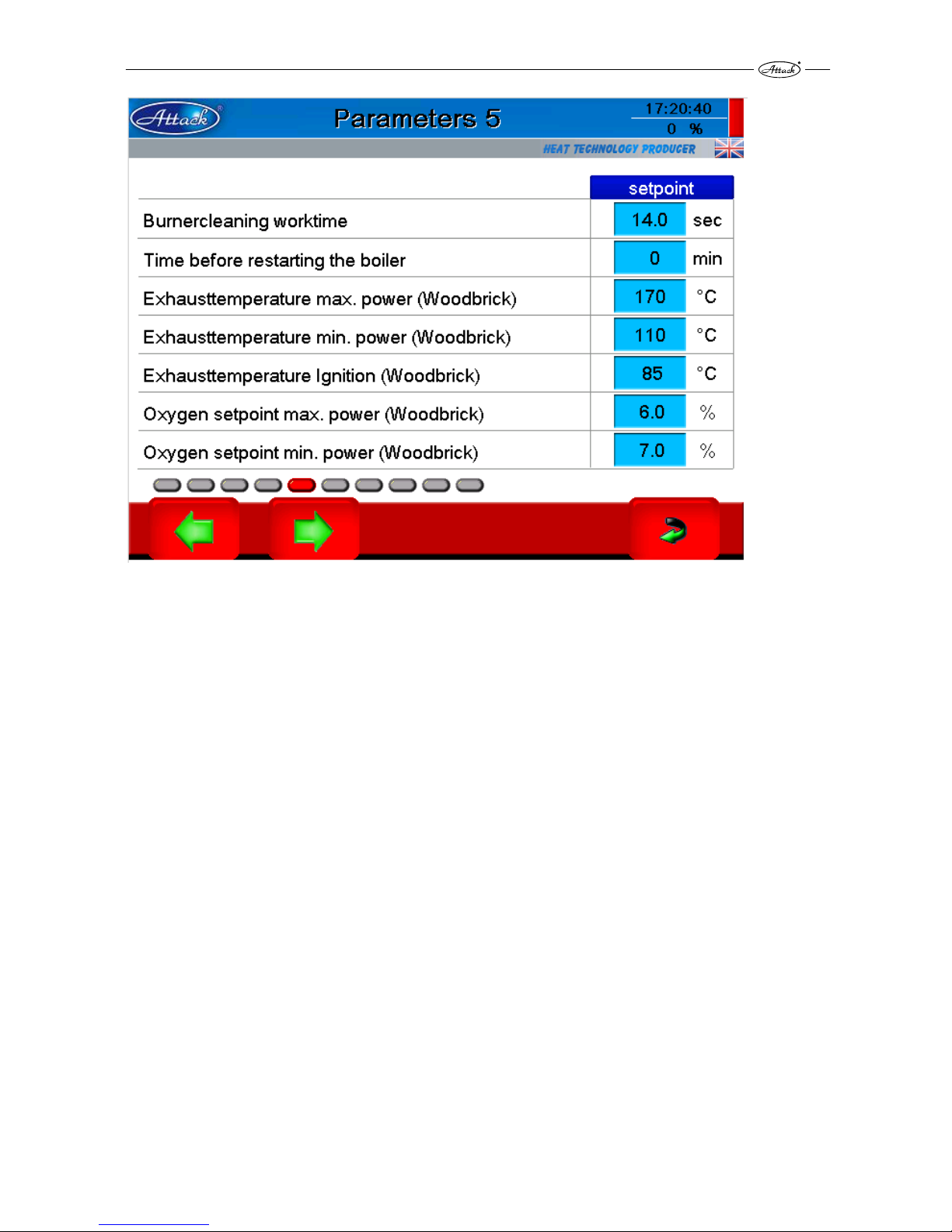
Pic. 31 Advanced parameters, page 5
Burner cleaning work time – time of moving the grate of the burner in and out to be cleaned
Time before restarting the boiler – when the wood or pellets burnm out, it is possible to set
the time, after which will the boiler start to work again.
Exhaust temperature max. power (Wood brick) – the boiler has to achieve this flue gas
temperature during its max. output by wood burning
Exhaust temperature max. power (Wood brick) – the boiler has to achieve this flue gas
temperature during its min. output by wood burning
Exhaust temperature ignition (Wood bricks) – after achieving this flue gas temperature the
boiler considers the wood ignition as successful
Oxygen setpoint max. power (Wood bricks) – the boiler will control the burning process
according to this value for the max. output
Oxygen setpoint min. power (Wood bricks) – the boiler will control the burning process
according to this value for the min. output
Page 44

44
Pic. 32 Advanced parameters, Page 6
Feeding cycle at 100 % power – the cycle of the pellet feeding into the burner
Feeding time at 100 % power – cycle time of pellets loaded into the burner
Difference temp. power regulation (Wood brick)– when the actual temperature decreases in
comparison with the adjusted temperature for this value, the boiler is started again.
Exhaust temperature regulation start – by this flue gas temperature will the boiler start to
control the wood burning process by the Lambda probe.
Maximum power (Pellet) – the max. output of the burner operation
Page 45

45
Pic. 33 Advanced parameters, page 7
Primary – airflap max. open– max. opening of the primary flap
Secondary – airflap max. open– max. opening of the secondary flap
Secondary airflap ignition (Wood brick) – position of the flap during wood ignition
Secondary airflap pre-heating (Wood brick) – position of the secondary flap for the phase of
the wood pre-heating
Ignition max. time (Woodbrick) –the flue gas temperature must achieve this value of flue gas
during wood ignition. If this temperature is not reached, the boiler is stopped and the fuel
shortage is indicated.
Page 46

46
Pic. 34 Advanced parameters, page 8
Exhaust Fan Autom. Ignition (Wood) – the fan output during the automatic wood light up by
pellets
Primary Air Flap Autom. Ignition (Wood) – position of the primary flap during the wood light
ignition by pellets
Secondary Air Flap Autom. Ignition (Wood) – position of the secondary flap during the wood
light up by pellets
Power regulator worktime – time of conversion of the PID control model
Power regulator P – part – a proportional part of the PID control model
Power regulator D – part - difference part of the PID control model
Power regulator I – part – integral part of the PID control model
Page 47

47
Pic. 35 Advanced parameters, page 9
Pump delay – time of the pump over run, when the temperature gets back under the safety
temperature of the pump start
Pump safety temperature – when this temperature is be exceeded, the pump will run
Turbine max runtime – time limit for the max. period of operation of the vacuum motor
Turbine rest time – time to cool down the vacuum motor
Number of suction retries – max. number of repeating the suction of the vacuum motor into
the integrated tank
Automatic pellets suction – option to turn the automatic pellet feeding off
Size of pellet tank – given in seconds (during this period the auger feeder is able to empty the
integrated pellet tank)
Pic. 36 Advanced parameters, page 10
Ignition retry numbers – if the pellet ignition in the burner fails, it is possible to repeat it again.
The number of trials can be set.
Page 48

48
9. SPECIAL SETTINGS AND INFORMATION
The following special settings can be made in the boiler ATTACK WOOD&PELLET (Pic. 37)
Pic. 37 The special settings are displayed after pressing the key sign.
Set Time, Set Date – it is possible to set the date and time. If the boiler is disconnected from the
electricity mains or the power supply fails, the date and time are in the memory for
approximately 3 days.
Screen saver – defines the time, when the screen saver is activated.
Program version – information about the actual program version
PLC Serial No. – the serial number of electronics
Alarms messages – enables the sound notification of errors and notifications of the boiler.
Automatic quit – if it comes to errors like a fail of ignition, flame loss or failure of the pellet feed,
they can be automatically erased and the boiler can be started again. This is possible only by
small errors. The problems like the damaged boiler temperature sensor or damaged flue gas
temperature sensor cannot be automatically erased. The time, after which will be the error
erased can be defined by the “after” parameter.
Page 49

49
10. INTERNET CONNECTION
The boiler can be connected to the internet by the LAN and it can be regulated through the
remote control. The control is available via the local network and via internet as well. It is
necessary to have the IP address from the internet provider to have an access from internet.
The LAN cable has to be connected in the following way:
1. Prepare the LAN cable of appropriate length. The length of the cable in the boiler is
approximately 2,6 m.
2. Disconnect the boiler from the electricity mains.
3. Undo the rear covering.
4. Undo the cover of electronics.
5. Undo the internal zinc plate on the upper door to get an access to the touch display.
6. Lead the cable from the rear side of the right covering, around the electronics and through
the opening in the middle door to the connector placed on the bottom side of the touch
display, marked as the ETHERNET.
7. Mount the dismantled parts back.
8. Set the correct parameters of connection to the network (Pic. 38).
Pic. 38 Setting the IP address for communication via the LAN or internet
The boiler can be reached and controlled also by the smartphone applications:
Android: Mocha VNC Lite
iOS: Mocha VNC Lite
Destination port: 1954
Pasword: attack
Page 50

50
Pic. 39 Setting the time programs of the operation under the pellet mode
11. SOFTWARE UPDATES
The software of the electronics can be updated by the trained technician by the USB key.
Page 51

51
12. FACTORY SETTINGS AND RESET
If there is a fatal error of the boiler occurred and the boiler is in fatal state, in which the error
cannot be removed or the boiler mode cannot be changed, it is necessary to restart the boiler.
The option of reset is displayed after entering into the special settings and click on the floppy
disc icon (Pic. 40). After click on the floppy disc you will see several windows. To reset the boiler
and to reset the original settings, press the “Restore Factory Settings”.
Pic. 40 Reset of the factory settings
13. BOILER MAINTENANCE
To ensure the correct boiler function during its life, it is necessary to do the maintenance. The
frequency of the maintenance depends on the frequency of operation and usage of the boiler.
The maintenance of the heating system and the boiler
The level of the water in the system has to be checked and eventually filled at least once in 14
days.
If the boiler is out of order during the winter period, the water could freeze in the system.
Thereby it is better to empty the system or to fill the antifreeze mixture. Otherwise should be the
water removed from the system just in the necessary cases and for the shortest time possible.
After the end of the heating season it is necessary to clean the boiler and to replace the
damaged parts. Undo the ventilator two times a year and clean the radial impeller and the air
chamber of the ventilator.
Tightening the hinges and exchange of the sealing cord of the door
The cords of the door are losing their elasticity by the ordinary operation and thereby they
decrease their tightness. To increase the tightness when doing the maintenance, it is possible to
change the position of the cord in direction into the boiler and to make it more pressed. When
the cord totally loses its elasticity, or when the hinges cannot be shifted further into the boiler, it
is necessary to exchange the cord. Remove the old sealing cord by a screw driver and clean the
groove, where it was placed. Take the new cord and place its ending into the horizontal parts of
the groove. Use your hand or the hammer to press the cord into the groove around the door.
Release the hinges and find the appropriate position of the hinges according to the door.
Page 52

52
14. BOILER CLEANING
To ensure the correct boiler operation and the appropriate comfort and life, it is necessary to
clean it regularly.
CAUTION
Always clean the boiler regularly and properly, otherwise it my cause decreased boiler life
or wrong burning. If the boiler is not cleaned regularly and sufficiently, the warranty is not
valid.
The boiler must be cleaned regularly and properly, every 3–5 days, because the ash accumulated
in the feeding chamber or the combustion chamber together with the condensate and tar
significantly decrease the lifetime, output and efficiency of the boiler.When there is more ash,
there is not enough space for fuel burn-out and the holder of the ceramic nozzle could get
damaged and thereby the whole boiler would be damaged. Remove the ash and soot through
the bottom opening. Open the bottom door and clean the bottom space form dirts. The
frequency of cleaning depends on the quality (humidity) of wood and the intensity of heating,
chimney draught and other conditions. We recommend to clean the boiler 1× a week. Do not
take the refractory piece out, when the boiler is being cleaned.
It is necessary to clean the following places in the below mentioned intervals:
feeding chamber of the gasification part (every 3 days)
combustion chamber of the gasification part (everytime before loading)
space under the combustion chamber of the gasification part (everytime before loading)
removable ash tray of the pellet part (depends on a boiler usage, but at least every 2 weeks).
burner grate (2× a year)
pellet chamber (1× a year)
radial impeller of the ventilator (2× a year)
air chamber of the vetilator (2× a year)
pipes of exchanger (1× a year, it is necessary to undo the turbulators)
integrated pellet tank from the residual pellet powder (depends on the operation, at least 1×
a year)
filter of the integrated tank (1× a year)
Pic. 41 Cleaning of the feeding chamber and the combustion chamber
Page 53

53
15. ASSEMBLY AND DISSASSEMBLY OF THE REFRACTORY
ITEMS
The estimated lifetime of the refractory pieces is the same as the lifetime of the boiler. Thereby it
is not necessary to disassembly them for exchange, if they are not damaged.
Pic. 42 Assembly and disassembly of the refractory pieces
On the Pic. 42 you can see, how to assemble the refractory pieces.
Assembly of the refractory items:
Assembly the refractory items in the correct order. As the first, insert the item marked as the nr. 1
through the bottom door on the water rib and shift it totally rearwards.Then, insert the item
number 2 (through the bottom door as well), put it on the water rib and shift it snugly to the
item number 1. Prepare the sealing cord, put the 300 mm part on the rear side of the item nr. 1.
Fit 2 pcs. of 75 mm vertically to ensure, that secondary air will not flow into the item nr. 3.
Put the item nr. 3 on the item nr. 1 and shift it rearwards. Insert the item nr. 4 with the arrow in
direction to the internal part of the boiler. Insert the refractory nozzle marked as the nr. 5. Then,
tighten the upper sides of the refractory pieces nr. 3 and 4. Tighten the nozzle nr. 5 by a special
INCONEL cord, which is more resistant against temperature.
Page 54

54
16. TABLE OF RELATION OF THE RESISTANCE AND THE
TEMPERATURE OF THE SENSOR PT 1000
The characteristics relates to the boiler temperature sensor and to the flue gas temperature
sensor as well:
Temperature [⁰C] Resistance [Ω]
-20 921
-10 960
0 1 000
10 1 039
20 1 077
30 1 116
40 1 155
50 1 193
60 1 232
70 1 270
80 1 308
90 1 347
100 1 385
110 1 422
120 1 460
130 1 498
140 1 535
150 1 573
160 1 610
170 1 647
180 1 684
190 1 721
200 1 758
210 1 795
220 1 831
230 1 868
240 1 904
250 1 940
By measuring the resistance of the sensor and the temperature using the energy meter you can
easily check, if the sensor is broken and is achieving the correct characteristics. If the sensor
indicates the values that are significantly different from the above given characteristics or if it
does not indicate anything, it could be faulty and it should be replaced.
CAUTION
The sensors of the boiler temperature and the flue gas temperature have the same
characteristic, but the different temperature resistance. Thereby they are not interchangeable!
Page 55

55
17. ELECTRICAL CONNECTION SCHEME
Description of the electrical scheme:
CL – motor of the burner cleaning
FL – flap of the air inlet into the burner
HS – ignition coil
F – female
M – male
FAN – ventilator of the burner
HALL – sensor of rotations of the burner´s ventilator
PH – photocell
GND – grounding
P – servogear of the primary air of the gasification part
S – servogear of the secondary air of the gasification part
M1 – motor of the vacuum pellet supply
M2 – motor of the gear for turbulator cleaning
M3 – exhaust fan
EL – electrical lock
MD – end-switch of the main door
FD – end-switch of the door of the feeding chamber
CARD – place for a memory card with software
LAN – place of the internet connection
STB – emergency thermostat
Tex – flue gas temperature sensor
Tb – boiler temperature sensor
LS – lambda probe
PS – sensor of the pellet presence
BR – burner
EMC – filter
L – phase
N – neutral
PE – grounding
S – signal
Colours of conductors:
A – black
B – blue
C – green-yellow
D – red
E – white
F – brown
G – yellow
H – green
J – grey
Page 56

56
X10
X11X12
X13
1
2
3
4
5
6
~
1
2
3
4
5
6
1
2
3
4
5
6
7
8
9
L
N
PE
L
N
PE
L
N
PE
NO
C
NC
R
1
2
3
4
5
6
7
8
9
L
L
N
N
-
+
+24
PE
PE
N
L
N
L
-
+
+24
~
L
N
X35
X34
X33
X32
X31
1
2
3
4
+22V
PE
~
~
1
2
+22V
PE
3
4
F
M
M
F
M
F
F
C
D
P
S
1
2
PE
L
N
F
3
4
A
E
D
A
E
D
A
E
D
A
E
D
A
B
A
B
A
B
C
A
B
D
C
M4
FL
CL
L
N
GND
BR
E
H
F
HALL
PH
FAN
+10V
+10V
B
F
EAD
A
B
C
C
C
B
A
B
A
H
F
E
B
A
F
H
E
F
B
S
S
Page 57

57
X1X2
X3
X4
X5
X6
X7
X8
X9
L
N
PE
PE
L
N
PE
PE
L
L
L
N
PE
A
B
C
A
A
L
N
PE
A
B
L
N
PE
A
B
L
N
PE
L_O
L_C
N
PE
X30
X29
X28
X27 X26
X25
X24X23
X22
X17X16 X15
X14
X21
X20X19
X18
X36
X37
M1
M2
M3
A
B
D
C
M
G
F
E
H
LAN
CARD
LAN
Tex
Tb
LS
CO
E
PS
A
F
MD
FD
EL
3
4
M
33
A
B
1
1
2
L
N
FM
1
2
STB
32
E
D
1
1
F
M
E
H
D
A
E
D
E
J
A
E
E
J
A
A
B
PE
L
N
L
N
A
B
D
D
D
D
B
A
AEA
D
B
MF
MS
ES
EMC
Page 58

58
18. ACCESSORIES
The ATTACK WOOD&PELLET boiler is delivered functionally tested, packed and placed on
a wooden pallet.
The following accessory items are delivered:
Instruction manual
Warranty letter
USB key with software
Firehook
The following items can be optionally ordered:
The REGUMAX regulator to control the other devices in the heating system
Vacuum pellet tank
Supply hoses for the vacuum pellet tank
Ashtray suitable for the boiler cleaning
19. INSTRUCTIONS FOR DISPOSAL OF THE APPLIANCE
AFTER ITS LIFETIME ENDS
Ensure the disposal of the appliance (boiler) by the waste disposal service, eventually use the
regulated waste dump, controlled by the municipal authority.
19.1 DISPOSAL OF PACKAGING
Dispose the packaging by the waste disposal service, eventually use the regulated waste dump.
Page 59

Stamp, signature of the service organization: ....................................
Obligatory service inspection after the 1st year of operation
Date: .............................
Obligatory service inspection after the 2nd year of operation
Obligatory service inspection after the 3rd year of operation
Stamp, signature of the service organization: ....................................Date: .............................
Stamp, signature of the service organization: ....................................Date: .............................
Data of the customer: (legibly)
Name and surname:
...........................................................................
Street: ................................................................
ZIP code, town: ..................................................
Tel.: ....................................................................
Boiler commissioning certificate
Serial number: ...............................................
Date of commission: ......................................
Service organization:
.......................................................................
Stamp, signature
This page serves for confirming the service inspections and is kept by the customer!
Page 60

ATTACK, s.r.o. – 11/2014
ATTACK, s.r.o.
Dielenská Kružná 5020
038 61 Vrútky
Slovakia
Tel: +421 43 4003 103
Fax: +421 43 4003 116
E-mail: export@attack.sk
Web: www.attack.sk
Výrobca ATTACK, s.r.o. si vyhradzuje právo technických zmien výrobkov bez predchádzajúceho
upozornenia. • ATTACK, s.r.o. producer reserves the right to change technical parameters and dimensions
of boilers without previous warning. •Der Hersteller ATTACK, s.r.o. behält sich das Recht der technischen
Veräderungen an Produkten ohne eine vorige Warnung. • Изготовитель ATTACK, s.r.o. оставляет за собой
право изменения технических параметров и размеров котла без предыдующего предупреждения.
• Le producteur ATTACK, s.r.o. réserve le droit des modifications techniques sans l‘avertissement
précédent. • Productor ATTACK, s.r.o. reserva el derecho de cambios técnicos sin advertencia anterior.
 Loading...