

ATTACK ATTACK DPX 45 COMBI Pellet, ATTACK DPX 35 COMBI Pellet, ATTACK DPX 30 COMBI Pellet, ATTACK DPX 25 COMBI Pellet, ATTACK DPX 50 COMBI Pellet Instructions For Use Manual
...Page 1
EN
EN 07/ 2019
ATTACK DPX
COMBI PELET
Instructions for use
www.attack.sk
Page 2

Page 3

EN
CONTENT
1INTRODUCTION ................................................................................................................................................... 4
1.1GENERAL DESCRIPTION ............................................................................................................................ 4
1.2IMPORTANT INFORMATION .................................................................................................................... 5
1.3SAFETY ............................................................................................................................................................ 6
1.4BOILER OPERATION .................................................................................................................................... 6
1.4.1PROTECTIVE EQUIPMENT FOR BOILER OPERATION ........................................................................... 6
1.5FUEL ................................................................................................................................................................. 6
1.5.1WOOD ............................................................................................................................................................ 6
1.5.2PELLETS .......................................................................................................................................................... 7
1.5.3ALTERNATIVE FUELS ................................................................................................................................... 7
2ASSEMBLY AND INSTALLATION OF THE BOILER ...................................................................................... 8
2.1MANIPULATION WITH THE BOILER ....................................................................................................... 8
2.2GENERAL CONDITIONS FOR INSTALLATION ...................................................................................... 8
2.2.1BINDING NORMS FOR PROJECTING AND INSTALLATION OF THE .................................................. 9
BOILERS.......................................................................................................................................................... 9
2.3PLACING THE BOILER .............................................................................................................................. 10
2.4BOILER CONNECTION TO THE HEATING SYSTEM .......................................................................... 11
2.4.1ANTIFREEZER USING................................................................................................................................. 11
2.4.2BOILER PROTECTION AGAINST CORROSSION.................................................................................... 11
2.4.3CHIMNEY ..................................................................................................................................................... 12
2.4.4FLUE GAS CONNECTION .......................................................................................................................... 12
2.4.5BOILER CONNECTION TO THE ELECTRICITY MAINS ......................................................................... 12
2.4.6CONNECTION WITH EXTERNAL PELLET TANK AND PELLET FEEDER ........................................... 13
2.4.7BURNER CONNECTION TO THE BOILER AND BOILER TEMPERATURE SENSOR ......................... 14
2.4.8CHOICE AND CONNECTION OF THE CONTROL AND REGULATION COMPONENTS ................. 14
2.4.9BOILER PROTECTION AGAINST OVERHEATING ................................................................................. 15
2.4.10CONNECTION TO THE ACCUMULATION TANKS ................................................................................ 15
3TECHN. PARAMETERS FOR ATTACK DPX COMBI PELLET .................................................................... 17
4DIMENSIONS OF BOILER ATTACK DPX COMBI PELLET ........................................................................ 18
5PURPOSE OF USE ............................................................................................................................................. 19
6TECHNICAL DESCRIPTION ............................................................................................................................. 20
6.1TECHNICAL DESCRIPTION OF ATTACK DPX COMBI PELLET ...................................................... 21
6.1.1OPERATING PRESCRIPTIONS .................................................................................................................. 21
6.1.2HEATING UP AND OPERATION .............................................................................................................. 21
7OPERATION OF BOILER ATTACK DPX COMBI PELLET .......................................................................... 23
7.1OPERATION OF BOILER ATTACK DPX COMBI PELLET – WOOD MODE .................................. 24
7.2ADVANTAGES OF THE REGULATOR ................................................................................................... 25
7.3BASIC DESCRIPTION OF THE REGULATOR ....................................................................................... 25
7.4CONNECTION OF THE REGULATOR BY HYDRAULIC SCHEMES................................................. 26
7.5REGULATOR CONTROL AND OPERATING MODES ........................................................................ 31
7.6SETTING THE USER PARAMETERS ....................................................................................................... 31
7.7SETTING THE SERVICE PARAMETERS ................................................................................................. 33
7.8DESCRIPTION OF PARAMETERS .......................................................................................................... 34
7.9ERROR MESSAGES .................................................................................................................................... 37
7.9.1ERROR MESSAGES DISPLAYED .............................................................................................................. 37
7.10DISASSEMBLY OF THE REGULATOR ................................................................................................... 38
7.11TECHNICAL SPECIFICATION OF THE REGULATOR ......................................................................... 38
7.12OUTPUT CONTROL OF ATTACK DPX COMBI PELLET.................................................................... 38
2
Page 4

EN
7.13OPERATION WITH PERMANENT BURNING ...................................................................................... 38
8BURNER ASSEMBLY TO THE BOILER .......................................................................................................... 39
9OPERATION OF BOILER ATTACK DPX COMBI PELLET – PELLETS MODE ........................................ 40
9.1ATTACK PELLET BURNER AUTOMATIC 8–30 KW ........................................................................... 43
9.2ATTACK PELLET BURNER AUTOMATIC 15–50 KW ......................................................................... 44
9.3BURNERS DIMENSIONS .......................................................................................................................... 45
9.4DESCRIPTION OF FUNCTION ................................................................................................................ 46
9.4.1NORMAL START–UP IN STAND–BY MODE OF BURNER .................................................................. 46
9.4.2BURNER START–UP, WHEN THERE IS STILL FIRE IN THE BURNER................................................. 46
9.4.3BURNER START–UP, WHEN THE CONTROL SYSTEM DOES NOT RECOGNIZE THE FIRE........... 46
9.5MENU AND FUNCTIONS ........................................................................................................................ 47
9.5.1INDICATIONS ON DISPLAY ...................................................................................................................... 47
9.5.2MENU INDICATIONS ................................................................................................................................. 48
9.6PRODUCTION SETTINGS ........................................................................................................................ 49
9.6.1ATTACK PELLET BURNER AUTOMATIC 8–30 KW .............................................................................. 49
9.6.2ATTACK PELLET BURNER AUTOMATIC 15–50 KW ............................................................................ 51
9.6.3HOW TO CHANGE PRODUCTION SETTINGS ....................................................................................... 52
9.7ADVANCED MENU ................................................................................................................................... 52
10MAINTENANCE OF THE BOILER ................................................................................................................... 56
10.1BOILER CLEANING .................................................................................................................................... 57
10.2INSTALLATION AND REPLACEMENT OF THE FIREPROOF PARTS ............................................. 58
11TRANSPORT, HANDLING AND STORING .................................................................................................. 60
11.1INSTRUCTIONS FOR PRODUCT DISPOSAL AFTER TERMINATION OF ITS SERVICE LIFE..... 60
11.2DISPOSAL OF THE PACKAGING ........................................................................................................... 60
11.3ACCESSORIES ............................................................................................................................................ 60
12POSSIBLE ERRORS AND SOLUTIONS .......................................................................................................... 61
12.1CHARAKTERISTICS OF TEMPERATURE SENSORS ........................................................................... 64
13ELECTRICAL SCHEMES .................................................................................................................................... 65
13.1ATTACK DPX 25, 30, 35 COMBI PELLET ............................................................................................. 65
13.2ATTACK DPX 40, 45, 50 COMBI PELLET ............................................................................................. 67
14RECOMMENDED SCHEMES OF CONNECTION ........................................................................................ 69
14.1CONNECTION OF THE BOILER WITH 1 HEATING CIRCUIT WITH DHW .................................... 69
14.2CONNECTION OF THE BOILER WITH 1 HEATING CIRCUIT WITHOUT DHW .......................... 70
14.3CONNECTION OF THE BOILER WITH 2 HEATING CIRCUITS WITHOUT DHW ........................ 71
14.4CONNECTION OF THE BOILER WITH 2 HEATING CIRCUITS WITH DHW ................................. 72
3
Page 5

EN
1 INTRODUCTION
Dear customer,
thank you for your trust and purchase of our product – the ATTACK COMBI Pellet boiler. We wish it
serves you reliably for a long time. The reliable and correct function of device is related to its operation and therefore it is necessary to read this user manual. The manual is written with respect to the
correct function of the boiler.
The correct function of the boiler particularly depends on the following:
• choice of the correct boiler output and type
• perfect commissioning
• reasonable operation
• regular professional maintenance
• reliable service
1.1 GENERAL DESCRIPTION
Name: Water heated boiler ATTACK DPX 25, 30, 35, 40, 45, 50 COMBI Pellet
for wood and wood pellets
Type: ATTACK DPX 25, 30, 35, 40, 45, 50 COMBI Pellet
Max. operating pressure: 250 kPa
El. power supply: 230 V/50 Hz/10 A
El. input: 38 – 78 W
Fuel: Dry wood with heat value of 15 – 17 MJ/kg, moisture of 12 – 20 %,
diameter of 80 – 150 mm
Wood pellets ∅ 6 mm, l
Nominal output: 25; 30; 35; 40; 45; 49,9 kW
Combi boiler ATTACK® DPX COMBI Pellet is intended for economical and ecological heating of
family houses, cottages, small plants and similar objects.
= 35 mm
max
4
Page 6
EN
1.2 IMPORTANT INFORMATION
• Installation, heat–up test and user training must be performed by the technician trained by
producer. The technician must fill the protocol about the installation of the boiler.
• By gasification of wood it comes to creation of tar and condensates (acids) in the fuel tank.
Due to this there must be a mixing device installed behind the boiler to keep the minimum
temperature of return water at 65 °C. The temperature of water in the boiler during its operation must be within the range of 80 – 90 °C.
• The boiler must not be permanently operated within the output lower than 50 %.
• If the circuit pump is being used, its operation must be controlled by a separate thermostat
to ensure the prescribed minimum temperature of the return water.
• Ecological boiler operation is related to its nominal output.
• It is recommended to install the boiler together with the accumulation tank and mixing de-
vice. This ensures the fuel saving of 20 – 30 % and longer lifetime of the boiler and chimney.
• If it is not possible to connect the boiler to the accumulation tank, it should be connected
with at least one equalization tank with the volume of approximately 25 l / 1 kW of the boiler´s output.
• By the operation with lower output (summer operation and D.H.W. preparation) it is neces-
sary to heat the boiler up every day.
• Only the dry fuel of 12 – 20 % moisture can be used (by the higher moisture of fuel is the
boiler output decreased and its consumption increased).
• Due to the economical operation and correct functionality it necessary to choose an appro-
priate boiler output. The nominal output of the boiler has to be adequate to the temperature
loss of the heated object.
WARNING! When the boiler works in PELLET mode, the primary and secondary air
flaps must be closed.
ATTENTION: The boiler must be used only for the purpose that it is intended for and
only in the way given in this manual.
The warranty for the boiler is not valid:
• if it is not operated with the prescribed fuel.
• if no mixing device Regumat ATTACK–OVENTROP is installed in the system to ensure the re-
turn water temperature of at least 65 °C during the boiler operation.
• if no functional thermostatic valve is installed on the aftercooling circuit (WATTS STS20) of
the boiler, connected to the cold water inlet.
This device is not supposed to be used by persons (including children) with physical, sensual or
mental disability or insufficient experience due to which they are not able to use the device in a
safe way without being supervised or instructed about the boiler operation by the person responsible for their safety. Do not to allow the children to play with the device.
If the power supply cable is damaged, it must be replaced with a special cable available by
producer or by a service technician!
5
Page 7
EN
MJ/kg
1.3 SAFETY
This manual uses the following warning signs to illustrate the severity of the impending danger
and important safety information:
WARNING!: Imminent dangerous situation, if not taken the right steps, may occur in serious injury or property damage. Act under the above instructions!
CAUTION: There may be a dangerous situation and if not taken the right steps, can occur
in serious injury or property damage. Work with extreme caution!
ATTENTION: There may be a dangerous situation and if not taken the right steps, can
occur in serious injury or property damage.
1.4 BOILER OPERATION
ATTENTION: If entered the boiler room unauthorized persons, can occur in serious injury
or property damage. The system operator must ensure the boiler room for access by un-
authorized persons and especially children.
1.4.1 PROTECTIVE EQUIPMENT FOR BOILER OPERATION
By boiler operation, it is necessary to use protective equipment in accordance with established
rules on safety at work. Extra care must be taken to protect the health by operation, cleaning
and inspection of the boiler. It is necessary to wear gloves with increased heat resistance, suitable clothing and sturdy shoes.
1.5 FUEL
1.5.1 WOOD
The ATTACK DPX COMBI Pellet can be used soft and hard chopped firewood with a heat value
15 – 17 MJ/kg. Ideal are especially beech, oak, fir, spruce, pine, poplar, alder, willow, birch, ash,
hornbeam, acacia, each with a moisture 12 – 20 %. A suitable diameter of the logs is 80 –
150 mm. The maximum length of the logs must not exceed 580 mm in order to prevent jamming of the logs in the loading chamber.
Heat value of different type of wood:
Wood Kcal/kg
Spruce 3 900 16,25 4,5
Pine 3 800 15,80 4,4
Birch 3 750 15,50 4,3
Oak 3 600 15,10 4,2
Beech 3 450 14,40 4,0
ATTENTION: Wrong moisture or size of wood can be reduced or increased output, low or
high temperature of flue gas, excessive condensation, loss of flame by gasification or
uncontrollable combustion.
Units
kWh/kg
6
Page 8

EN
Recommended storage and drying of wood:
Hard wood: 2 years stored in a dry place
Soft wood: 1 year stored in a dry place
Wood during storage (drying) must be protected against rain. Effective drying of wood can
help,that the wood will be saved with the largest possible air gaps. Then air can flow between
the pieces of wood. When drying there are places where wind operates for wood. It helps in
faster drying of wood. If it is possible, before loading of wood into the boiler, keep it at least one
day in a warm place such as a boiler room (this increases the combustion efficiency).
1.5.2 PELLETS
In the boiler can be used only pressed wood pellets without additional materials and the following parameters:
Specification of pellets:
Specific weight: 600 – 750 kg/m
Heat value: 4,7 – 5,0 kWh/kg
Size/diameter: 6 mm
Size/length: Max. 35 mm!
Moisture max.: 12 %
Ash content: 0,5 – 1 %
Dust content: max. 3 %
Ash fusion temperature: min. 1 100 °C
Standards: DIN 51 731 – HP 5, DIN Plus, or EN 14961–2 – A1
3
1.5.3 ALTERNATIVE FUELS
In the boiler can be also used wood briquettes with a hole, pressed from wood dust without additional connecting materials. Wood briquettes must always be mixed in a certain ratio together
with the log (the ratio depends on the size and shape of the briquettes) to prevent stoppage of
the nozzle for the gasification of wood.
ATTENTION: Illegal type of fuel increase demand for cleaning and lead to the accumula-
tion of aggressive sedimentation and condensation, which at the end can lead to reduced functionality, boiler damage and void warranty. The use of illegal fuel can cause
wrong and uncontrolled combustion.
7
Page 9
EN
2 ASSEMBLY AND INSTALLATION OF THE BOILER
2.1 MANIPULATION WITH THE BOILER
The boiler is delivered on pallet. Manipulation with the boiler always perform on the pallet. Only
if is boiler on installation place, remove the boiler from the pallet. This can be done with the help
of a handling truck or a crane and hanging ears, which are welded to the heat exchanger of the
boiler.
The way of boiler manipulation with welded ears
2.2 GENERAL CONDITIONS FOR INSTALLATION
Only a person with valid authorization for installation and assembly of the heat technology devices can install the boiler. The installation requires an appropriate project that is in line with the
valid prescriptions and this instruction manual. Before installing the boiler must the technician
check, if the data given on the production label are in conformity with the data in the project
and the documentation attached to the boiler. The boiler must be connected in line with the
valid prescriptions, regulations and this instruction manual.
ATTENTION: The producer takes no responsibility for damages caused by wrong
connection or operation!
8
Page 10

EN
2.2.1 BINDING NORMS FOR PROJECTING AND INSTALLATION OF THE
BOILERS
Boiler installation must meet the following norms:
STN EN 303–5:2012 Heating boilers for solid fuels
STN 73 42 10 Construction of the chimneys and flue connections
STN EN 60 335.1 +A11 Safety of the electrical appliances for household
STN EN 12828+A1 Heating systems in buildings. Design for water–based heating sys-
tems
STN 06 08 30 Safety devices for central heating and D.H.W. preparation
STN 07 74 01 Water and steam for thermal energetic devices with operation pres-
sure of steam up to 8 MPa
STN 332000 4–46 Electrical installations of buildings – part 4: Ensuring safety
STN 33 2000–1:2009–04 Electrical installations of buildings – part 3: Definition of the basic
characteristics
STN EN ISO 11202 Acoustics. Noise emitted by machinery and equip-
ment.Determination of emission sound pressure levels at a work
station and at other specified positions applying approximate envi-
ronmental corrections (ISO 11202:2010)
STN EN ISO 12100 Safety of machinery.General principles for design.Risk assessment
and risk reduction (ISO 12100:2010)
STN EN ISO 14120:2016 Safety of machinery. Guards. General requirements for the design
and construction of fixed and movable guards
STN ISO 27574–2 Acoustics. Statistical methods for definition and verification of the
determined values. Noise emission of machines and devices. Part 2:
Methods for particular of machines.
STN ISO 1819 Continuous mechanical handling equipment. Safety code. General
rules.
STN EN ISO 15614–1 Requirements for quality of the fusion welding of metal materials
STN EN 287–1 Welding of reserved technical devices
STN 07 0240 Low pressure boilers, technical prescriptions
STN 07 0245 Warm water boiler with the output up to 50 kW. Technical require-
ments, testing
9
Page 11

EN
2.3 PLACING THE BOILER
The boiler is intended to be installed and operated in the premises with the basic environment
(AA5/AB5) following the STN 33 2000–1:2009–04.
Boiler room must meet also the following conditions:
• The boiler room must not be potentially explosive environments, due to the fact that the
boiler is not suitable for use in such environments.
• The temperature in the boiler room must not fall below freezing point.
• Boiler provides no lighting. The customer must ensure sufficient light source according to
local standards and regulations.
• If the boiler will be installed at altitudes over 1 800 m, it is necessary to consulted this instal-
lation with the producer.
• The boiler room must be secured with a hole for good air circulation and also required inlet
for combustion air, but at least 200 cm2. The hole should be designed so that external
weather does not affect its function (rain, snow, wind).
By the boiler installation it is necessary to keep the safety distance of its surface from
flammable materials according to their degree of flammability:
• from materials of the flammability degree B, C1 and C2 200 mm
• from materials of the flammability degree C3 400 mm
• from materials of the flammability degree not approved 400 mm
Examples of classification of the building materials by their degree of flammability:
• degree of flammability A inflammable (bricks, blocks, ceramic tiles, mortar, parging)
• degree of flammability B partly flammable (heraklith, lignos, board from basalt felt, novodur)
• degree of flammability C1 difficult to ignite (hardwood (oak, beech), plywood, werzalit, hardened paper)
• degree of flammability C2 normal combustibility (softwood (pine, spruce), chipboard, solodur)
• degree of flammability C3 easily ignited (wood fibre boards, polyurethane, PVC, foam rubber, polystyrene)
The sealing board or protection covering (on the protected item) must exceed the boiler edge
for at least 300 mm. Also other items from flammable materials must be protected in this way, if
they are placed near the boiler and it is not possible to keep the safe distance.
If the boiler stands on a flammable surface, it must be protected by an inflammable, heat insulating mat, which exceeds the edge on the side of the feeding door and the ash tray door for at
least 100 mm. All materials of the A flammability degree can be used as an inflammable, heat
insulating mat.
The boiler must be placed in a such way ensuring sufficient space of at least 1 m from the front
and 0,5 m from the left (right) and rear side. It is necessary to leave the space of at least 1 m
above the boiler.
This space is necessary for basic operation, maintenance and eventual service of the boiler. It is
not allowed to place the boiler in dwelling premises (including corridors). There must be an
opening for the air inlet for burning of at least 200 cm2 depending on the boiler output.
ATTENETION: The items from flammable materials must not be laid on the boiler and in
the distance shorter than the permitted (safe) one.
The boiler must be turned off, if there is a danger of fire or explosion due to the work (e.g. work
with painting materials, glues, etc.).
It is not allowed to place the boiler in residential premises (including corridors)!
10
Page 12
EN
2.4 BOILER CONNECTION TO THE HEATING SYSTEM
Boiler ATTACK DPX COMBI Pellet must be installed in system complying with the quality of heating water as follows:
Slovak Republic: STN 07 7401:1991
Austria: ONORM H5195–1
Germany: VDI 2035
Switzerland: SWKI 97–1
Italy: D.P.R. no. 412
Before installing the boiler, it is necessary to flush (to clean) the whole heating system. The system can be filled only the water treated to the values under the STN 07 7401: 1992. The water
has to be clear, colorless, free of suspended substances, oil and chemically aggressive impurities
and must not be acidic (pH must be higher than 7,2).
Callosity of the water must not excess 1 mmol/l and concentration of the Ca²Ѐ must be lower
than 0,3 mmol/l.
ATTENTION: If these conditions are not kept, the warranty is not valid!
2.4.1 ANTIFREEZER USING
It is not recommended to use antifreezer because of their unsuitable properties for the boiler. In
particular, the reduction in heat transfer, large volume expansion, aging, damage rubber components. In urgent cases, it is possible to use antifreezer Alycol Term (manufacturer Slovnaft Bratislava) – according to the experience of the manufacturer, it could not be a decrease in the safety of use and significant effects on the boiler. Unless the specific conditions this method of frost
protection heating system feasible, non–performance functional parameters or any defects in
the boiler due to the use of other antifreezer, can not be addressed under warranty.
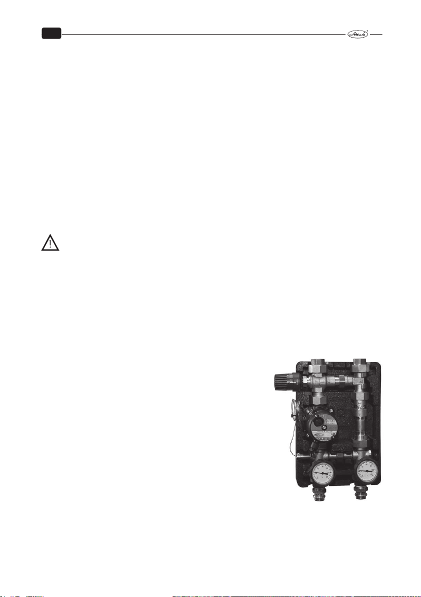
2.4.2 BOILER PROTECTION AGAINST CORROSSION
Use of the mixing device (Regumat ATTACK–OVENTROP) is
a suitable solution of the problem with corrosion. It enables
creation of the separate boiler and heating circuit. Thereby is
the boiler protected against undercooling below 65 °C and the
creation of water steams, acids and tars in the boiler´s feeding
chamber is eliminated.
The Regumat ATTACK–OVENTROP device keeps the constant
temperature of the return heating water flowing into the boiler
over 65 °C by setting the thermostatic head to the level 5 – 6.
When the individual thermal regulation mixing valve is used, it
is possible to control the temperature of the heating water independently on the temperature of water in the boiler by setting the flap. The temperature in the boiler has to be kept in the
range of 80 – 90 °C.
ATTACK–OVENTROP
11
Page 13

EN
ATTENTION: If is not installed in the system equipment against condensation, or the
equipment will not operate properly, can result in the formation of aggressive conden-
sate. It lead to boiler damage. Protection against condensation must be used during
operation of the boiler, otherwise it will void warranty by the manufacturer!
2.4.3 CHIMNEY
Connection of the appliance to the chimney hole must be always done with permission of the
appropriate chimney sweep association. The chimney must generate sufficient draught and take
the flue gas out into the atmosphere under the all operating conditions.
Correct dimensions of the chimney hole are important the correct boiler function, because the
burning, output and boiler life–time are influenced by the draught. The chimney draught directly depends on its diameter, height and roughness of the internal wall. It is not allowed to connect any other appliance to the chimney, where the boiler is connected. Diameter of the chimney must not be smaller than the connection part on the boiler. The chimney draught must
achieve the prescribed values, but it cannot be too high, not to decrease the boiler output and
interrupt the burning (flame). If there is too strong draught, install the throttle flap into the
chimney hole between the boiler and the chimney.
Prescribed dimensions of the chimney section:
20×20 cm min. height 7 m
∅ 20 cm min. height 8 m
15×15 cm min. height 11 m
∅ 16 cm min. height 12 m
The exact chimney dimension is defined by the STN 73 42 10. The prescribed chimney draught is
given in the Technical parameters.
2.4.4 FLUE GAS CONNECTION
The flue connection must lead into the chimney hole. If it is not possible to connect the boiler to
the chimney hole directly, then the appropriate extension should be as short as possible, of up
to 1 m length, without any additional heating area and it should ascend in direction to the
chimney. The flue connection must be mechanically tight (it should be mounted to the boiler
and tightly fixed by screws) and tight against the flue leakage. The flue connections must to lead
through the foreign dwelling or commercial premises. The internal diameter of the flue connection must not taper in direction to the chimney. It is not suitable to use the elbow connectors.
Flue must be connected to a chimney T–shaped to drop condensate from the chimney into an
aimed container and not to the boiler.
2.4.5 BOILER CONNECTION TO THE ELECTRICITY MAINS
The boiler is connected to the electricity mains of 230 V/50 Hz/16 A by an electrical cord with
plug. In the case of need, the power supply cord of the M type must be replaced with an adequate one by the service organization. The appliance must be placed in the way enabling to
reach the connection plug. The boiler must be connected to the 16 A socket circuit by a circuit
breaker (following the STN EN 60 335–1 + A11:1997).
12
Page 14

EN
2.4.6 CONNECTION WITH EXTERNAL PELLET TANK AND PELLET FEEDER
To the boiler ATTACK DPX COMBI Pellet is recommend to use ATTACK pellet tank in combination
with screwed ATTACK pellet feeder, length about 2 m. Pellet tank is possible to place on the
right or the left side of the boiler, where necessary. For 30 kW burner there is recommended PED200 feeder. Feeder PED210 is recommended for 50 kW burner. Between hole of
feeder and delivery tube on the burner should be a height difference at least 300 mm. In the
horizontal direction should be space between the hole of feeder and delivery tube at least 150
mm (i.e. not vertically aligned).
Before first starting up of the burner it is necessary to make setting of feeder (p. 58). For setting
of the feeder it is necessary to load the pellet tank with sufficient amount of pellets and load the
pellet feeder with connection to the mains until the pellets begin falling down of the top hole of
the feeder. Connect the feeder to the burner outlet. After correct setting of the feeder, install the
inlet hose between the outlet tube of feeder and the delivery tube of burner and adjust the
length of the hose. The hose should not be straight and also not so bented to prevent the pellets
inside of stacking and accumulating.
13
Page 15
EN
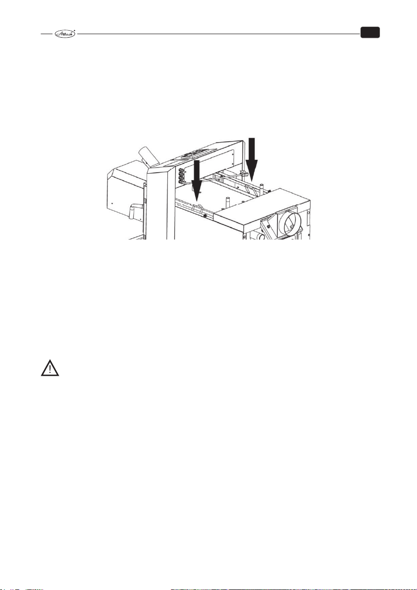
2.4.7 BURNER CONNECTION TO THE BOILER AND BOILER TEMPERATURE
SENSOR
Burner is connected to the boiler by cable with 6–pin connector that comes from the feet of
the boiler, at the point where
pantograph arm is fixed. The
cable is necessary after assembly to attach to the arm of the
pantograph by supplied plastic
tapes from the bottom of the
pantograph arms in a correct
distance so by manipulation of
the burner to prevent stretching
or strain of the cable. With the
cable is also connected the
boiler temperature sensor to
the arm of the pantograph. The
connector which is the sensor
completed, it is necessary to
connect in connector TS2 in
control electronic of burner.
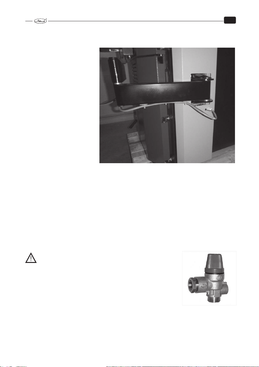
2.4.8 CHOICE AND CONNECTION OF THE CONTROL AND REGULATION COM-
PONENTS
The boiler is delivered with the basic regulation and control equipment. These should be supplemented by elements that are not part of the boiler delivery but must be installed in the heating circuit. They are mainly a safety valve (picture 4) against exceeding the allowable pressure in
the heating system (priecribe 2.5 bar), the valve of aftercooling circuit of the boiler to abduce
surplus heat from the boiler to the drain and vent valve for proper operation of the boiler. The
expansion tank in the system must have sufficient volume to be fixed by designer of heating
system under current regulations. Electric installation with the additional equipment of the boiler must be done by a specialist according to the current standards.
WARNING! The heating system must be equipped with
a safety valve against overpressure (2,5 bar). This valve is recommended to place on riser in front of shut–off valve of the boiler (or
before OVENTROP). If the safety valve will not be working, excess
pressure have nowhere to escape and the boiler may explode!
Safety valve against overpressure
14
Page 16
EN
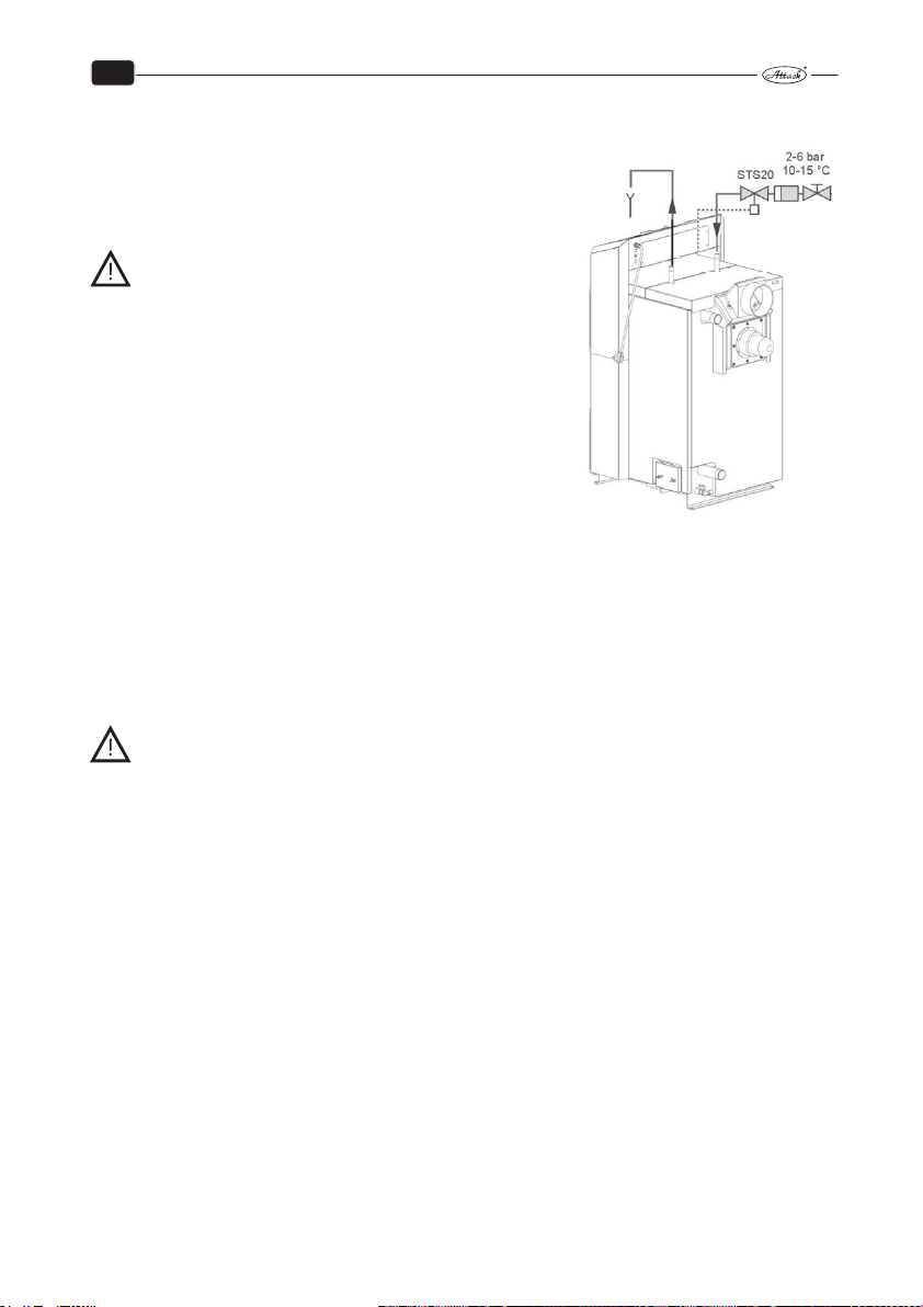
2.4.9 BOILER PROTECTION AGAINST OVERHEATING
Each gasification boiler must be equipped with functional
cooling circuit. The right valve to provide the feature can
be ordered as an accessory. The correct installation of the
cooling circuit valve can be seen in pic. on the right.
WARNING! Following the norm EN 303–5, the
aftercooling circuit against the boiler overheat-
ing must not be used for other purposes than
boiler protection against overheating.
The valve at the cold water inlet into the cooling loop
must be permanently open and the cooling loop of the
boiler must be connected to the functional cold water
distribution (e.g. to the cold water supply into the water
distribution network) with the temperature of 10 – 15 °C
and the operating overpressure of 2 – 6 bar. This valve also
ensure safe operation even in power cut.
The STS20 valve at outlet of the cooling loop with the sensor placed in the rear part of the boiler protects the boiler in the following way. When the temperature of water in the boiler exceeds 95 °C, then the water from the distribution network flows
into the cooling loop to absorb the surplus heat. In the case of boiler overheating and opening
the STS20 valve it is necessary to ensure the permanent outtake of the warmed water from the
boiler aftercooling circuit into the drain.
Functionality of aftercooling circuit and thermostatic valve can be tested each time manually,
with the manual button of the thermostatic valve.
WARNING! If the outtake of cooling water through the cooling loop is not ensured
after opening the STS20 valve, there is a danger of boiler damage! In this case is the
warranty for the boiler not valid!
2.4.10 CONNECTION TO THE ACCUMULATION TANKS
Connection system consists in heating of accumulation tanks heat. Accumulated heat of the accumulation tanks is gradually taken according to requirements into heated space. When is the
boiler operating at full output, the storage tanks are heated to 80 – 90 °C. Heating with accumulation tanks in connection with the boiler ATTACK DPX COMBI Pellet brings several advantages.
Highlights include the longer boiler life, cleaner operation and minimal creation of acid and
condensate, less frequently of fuel loading, higher comfort, less possibility of overheating of the
boiler and lower fuel consumption.
Recommended capacity of accumulation tank for boiler ATTACK DPX COMBI Pellet is 50 l per
1 kW boiler output, the minimum capacity is 25 l per 1 kW boiler output. When choosing
a capacity of accumulation tank, it is necessary to have on mind that the size of the accumulation tank affects on operation of the boiler. That means, we load the boiler regarding to the size
of accumulation tank to prevent overheating of the system.
Therefore is very important to have on mind that the boiler needs to be load always just with
enough wood, to heat up the accumulation tank, but not overheat. There may be to remove the
surplus heat to waste. This is uneconomical and requires activation of safety element – aftercooling circuit.
15
Page 17

EN
TUV
The bigger volume of the accumulation tank, the less risk of overheating. With the larger capacity of the accumulation tank is the loading time shorter.
Note:
It should be noted that the above is only relevant in the operation of boiler with WOOD.
In operation of PELLETS it loses meaning, the boiler need not be connected to the accumulation tank, but the boiler have to operate always only with PELLETS.
The ATTACK accumulation tanks available*
AK AS HR HRS
200 200 — — — — — —
300 300 — — — — — —
400 400 — — — — — —
500 500 600 600 500 500 500 500
800 800 800 800 600 600 800 800
1000 1000 1000 1000 800 800 1000 1000
1500 1500 1250 1250 1000 1000 1250 1250
2000 2000 1500 1500 1250 1250 1500 1500
2500 2500 2000 2000 1500 1500 2000 2000
3000 3000 — — 2000 2000 — —
4000 4000 — — — — — —
5000 5000 — — — — — —
AK – standard accumulation tank designed for accumulation of heating water
AS – accumulation tank for accumulating of heating water, equipped with a heating coil for
connection to solar panels
HR – combined accumulation for accumulation of the heating water as well as for preparation
of the D.H.W. by an internal enameled exchanger
HRS – combined accumulation for accumulation of the heating water as well as for preparation
of the D.H.W. by an internal enameled exchanger, equipped with a heating coil for connection to
solar panels
TUV – accumulation tank for accumulation of the heating water as well as for the D.H.W. preparation in a water coil
TUVS – accumulation tank for accumulation of the heating water as well as for the D.H.W.
preparation in a water coil, equipped with a heating coil for connection to solar panels
S – accumulation tank with internal disk and stratification pipe (based on the type AK) that allows layering of water as necessary (different water temperature on inputs as well on outputs)
SS – accumulation tank with internal disk and stratification pipe (based on the type AS and S),
equipped with a heating coil for connection to solar panels
* It is possible to cover required volume for required accumulation of energy by one or several accumulation tanks. Accumulation tanks can be connected together to create required volume of accumulation water. Therefore, if you decided that your accumulation volume will be 2 000 l, you can buy
a single accumulation tank of 2 000 l or two accumulation tanks with a capacity of 1 000 l and connect them together.
TUVS S SS
16
Page 18
EN
3 TECHN. PARAMETERS FOR ATTACK DPX COMBI PELLET
Parameter / Boiler type Jedn. DPX25CP DPX30CP DPX35CP DPX40CP DPX45CP DPX50CP
Nominal
output
Outout
range
Area of exchanger m² 2,52 2,52 2,78 2,78 3,03 3,03
Volume of feeding chamber l 125 125 158 158 190 190
Dimensions of the feeding opening mm 235×445 235×445 235×445 235×445 235×445 235×445
Prescribed chimney draught Pa 23 23 23 23 23 23
Max. operating overpressure of water kPa 250 250 250 250 250 250
Pressure loss of water (ΔT 10 K)
Pressure loss of water (ΔT 20 K)
Boiler weight kg 480 480 510 510 540 540
Diameter of flue connection mm 150 150 150 150 150 150
Boiler height mm 1 240 1 240 1 240 1 240 1 240 1 240
Boiler width mm 760 760 760 760 760 760
Boiler depth – „C“ with burner mm 1 510 1 510 1 610 1 610 1 765 1 765
Boiler depth with cov er of upper door mm 1 250 1 250 1 350 1 350 1 425 1 425
High of the outlet flue – "D" mm 985 985 985 985 985 985
High of ventilator – "E" mm 751 751 751 751 751 751
Depth of chamber mm 590 590 690 690 790 790
Protection of el. parts IP 21 21 21 21 21 21
Electrical
input
Boiler efficiency
Boiler class
Flue gas temperature by nominal
output – wood
Flue gas temperature by nominal
output – pellets
Flue gas temperature by minimal
output – pellets
Flue gas flow by nominal output kg/s 0,018 0,02 0,022 0,025 0,028 0,029
Flue gas flow by minimal output kg/s 0,005 0,007 0,009 0,012 0,014 0,015
Maximum noise level dB 65 65 65 65 65 65
Prescribed
fuel
Fuel consumption
Consumption of wood per season 1 kW = 1 m3
Maximum length of wood logs mm 550 650 650 750 750 750
Burning time by nominal output hod 4 4 4 4 4 4
Volume of water in the boiler l 100 110 110 128 128 128
Minimum volume of accumulation
tank
Connection voltage V/Hz 230/50
Min. temperature of return water °C 65
Range of setting the temp. of heating water
Capacity of contacts of the boiler regulator
Connection to the heating system " G6/4" G2"
Producer, the ATTACK, s.r. o., reserves right to make technical changes of p roducts without the previous announcement!
WOOD
PELLETS 30 30 30 40 45 49,9
WOOD
PELLETS 8 – 30 8 – 30 8 – 30 15 – 49,9 15 – 49,9 15 – 49,9
WOOD
PELLETS – on ignition 600
PELLETS 96 160 160 190 190 190
Stand–by mode <5
WOOD
PELLETS 90,8 90,5 90,2 90,6 90,5 90,2
WOOD
PELLETS 5
WOOD –
PELLETS –
WOOD
PELLETS 2,4 – 6,9 2,4 – 6,9 2,4 – 6,9 3,4 – 1 2,5 3,4 – 12,5 3,4 – 12,5
kW
kW
kPa 2,3 2,3 4,4 4,4 6,6 6,6
kPa 0,7 0,7 1 1 1,8 1,8
W
%
°C 165 170 185 170 180 185
°C 145 152 168 148 155 164
°C 109 116 129 110 119 126
Kg/h
°C 65 – 90
V/A 230/2
25 30 35 40 45 45
12 – 25 15 – 30 17 – 35 20 – 40 22 – 45 22 – 45
38 102 102 102 102 102
90,4 90,1 90,1 90,2 90,2 90,2
–
Dry wood with the heat value of 15 – 17 MJ/kg,
water content min. 12 % – max. 20 %, ∅ 80 – 150 mm
Wood pellets, ∅ 6 mm, l = 35 mm, humidity up to 12 %,
according to standards: DIN 51 731 – HP 5, DIN Plus, or EN 14961–2 – A1
6,5 7,8 9,1 10,4 11,75 11,75
l 625 750 900 1 000 1 200 1 200
5
17
Page 19
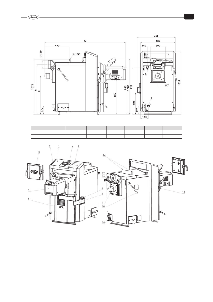
4 DIMENSIONS OF BOILER ATTACK DPX COMBI PELLET
EN
Flow connection „B“ G 6/4" G 6/4" G 6/4" G 2" G 2" G 2"
Return connection „A“ G 6/4" G 6/4" G 6/4" G 2" G 2" G 2"
DPX 25CP DPX 30CP DPX 35CP DPX 40CP DPX 45CP DPX 50CP
KEY DPX COMBI Pellet:
1. Boiler body 5. Pantograph 9. Inlet tube for pellets 13. Pull rod of the chimney flap
2. Pellet burner 6. Console 10. Lever for exchanger cleaning 14. Aftercooling circuit
3. Cover of boiler door 7. Upper boiler door 11. Suction fan 15. Flow connection
4. Boiler controller 8. Bottom boiler door 12. Flue gas opening 16. Return connection
Pull rod of the chimney flap – serves to close and to open the heat up flap (always by opening
the feeding door)
Lever for exchanger cleaning – serves to clean the holes of the exchanger
18
Page 20
EN
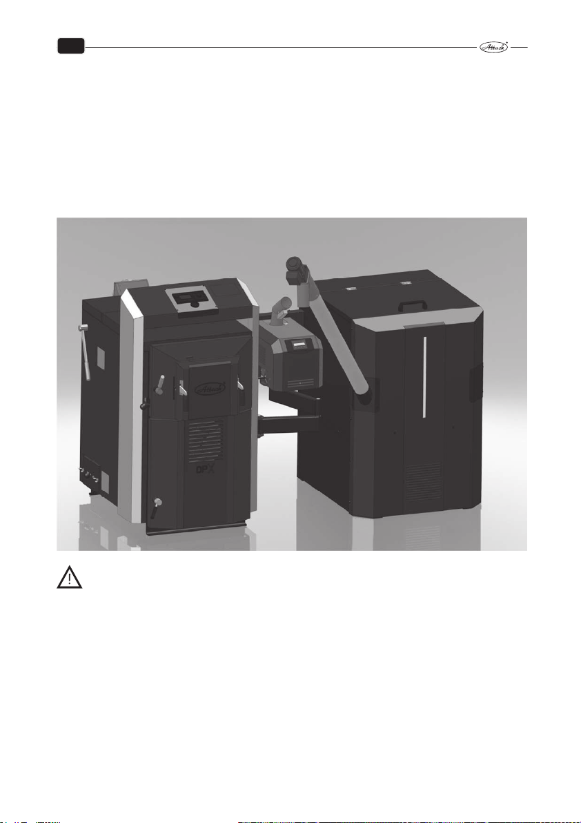
5 PURPOSE OF USE
The ecological warm water boiler ATTACK DPX is intended for heating the family houses and
other similar objects. The boiler is designed only for the use of wood logs. Any type of dry wood
can be used, especially the wood logs. It is also possible to use the blocks of wood with larger
diameter – then is the boiler output lower, but the time of burning is longer. The boiler is not
suitable to burn the saw dust and small wooden waste. Only small amount (approximately 10 %)
of such a material can be used together with the wood logs. Thanks to the voluminous feeding
chamber it is not necessary to do the most demanding work with wood – chopping into smaller
pieces.
WARNING! It is not allowed to operate with the boiler on both fuels at the same
time. It is never allowed to heat with wood until the burner is in upper loading door
of boiler and also is not allowed to heat with pellets if the wood is in loading chamber of boiler! It is also not allowed to use the pellet burner to ignite the wood. During the boiler operation with wood, it is always necessary to use the upper door
cover!
19
Page 21

EN
6 TECHNICAL DESCRIPTION
The boiler is designed to burn wood on principle of the wood gasification by using the exhaust
fan that sucks the flue gas from the boiler. In automatic pellet mode when is inserted the pellet
burner in the upper door, the boiler heat on wood pellets, which burn in the combustion chamber of the burner. Transport of pellets ensure the external pellet feeder from the external tank. It
is not allowed to operate with the boiler on both fuels at the same time.
The boiler body is welded from the steel plates of 3 – 6 mm thickness. In the feeding chamber
there is a fireproof nozzle with longitudinal opening for the flue gas and gas passage. In the
burning chamber there is a fireproof ashtray.
In the rear part of the boiler body is the tubular exchanger with the flue gas collector and the
heat up flap in the upper part.
In the front parts there is a feeding door and at the bottom there is the ashtray door.
Between the doors there are the primary and secondary air inlets placed under the boiler covering. In the left covering at the same level as the middle of the feeding door there is a pull rod of
the heat up flap that is controlled by the feeding door and there is also the lever for exchanger
cleaning.
The boiler body is insulated by a mineral wool, inserted under the external covering. The control
panel for electromechanical regulation is placed in the upper part of the boiler (operation with
wood).
On the right side to the heat exchanger is mounted the holder of console for pantograph system
for holding the burner. On the console are pins which attached two arms of the pantograph,
with burner door and the burner. ATTACK PELLET BURNER Automatic 8 – 30 kW or 15 – 50 kW
works on basis of the fuel feeding by the principle of falling, when the pellets fall by from the
pellet feeder through the inlet hose and the inlet tube on the grate, where they are burned. The
burner has an electrical ignition that automatically lights the pellets fallen on the grate. It is
equipped with a self–cleaning mechanism of the grate.
ATTACK PELLET BURNER Automatic 8 – 30 kW consists of combustion chamber from 3 mm heat–
resistant stainless steel, air chamber with fan and units for self cleaning mechanism of the grate.
Base of ATTACK PELLET BURNER Automatic 15 – 50 kW combustion chamber consists of combustion chamber from 4 mm heat–resistant stainless steel, air chamber, grate for pellet burning,
control units and self cleaning of the grate.
20
Page 22
EN
6.1 TECHNICAL DESCRIPTION OF ATTACK DPX COMBI PELLET
6.1.1 OPERATING PRESCRIPTIONS
Boiler preparation for operation
Before starting the boiler, it is necessary to check that the system is filled with water, deaerated
and the pressure of heating water does not decrease. Make sure that the sensors of the boiler,
safety thermostat and manometer are placed in casings on the upper rear side of the boiler.
Check the tightness and construction of the flue connection. The boiler has to be operated in
line with the instructions given in this manual to achieve its good service. By boiler installation
you can underlay it for 10 mm to enable better flush by water and deaeration. Only an adult
trained person with completed elementary education can operate the boiler.
ATTENTION: By the first heat up it may come to condensation and leakage of the con-
densate – it is not a fault. There will be no more condensate after heating for a longer
time. In the case that the smaller wooden waste is being burned, it is necessary to check the flue
gas temperature which should not exceed 320 °C. Otherwise it could damage the fan. By the
gasification of wood it is normal that tar and condensates are created.
If the boiler has been out of order for a longer period, it is necessary to be more careful by starting it again. It could come to the pump blockage, leakage of water from the system or to the
boiler freezing in the winter.
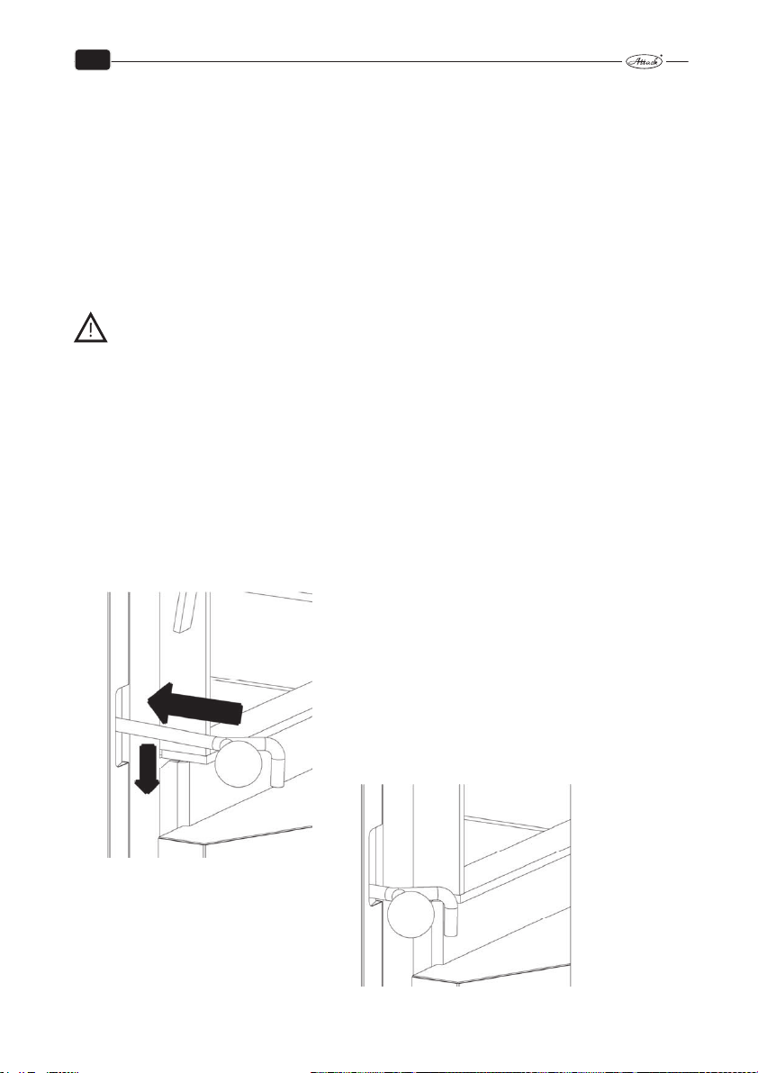
6.1.2 HEATING UP AND OPERATION
Before igniting the fuel, open the feeding door and push the pull rod of the heat up flap back to
the basic position until is the latch fixed (like when the door is closed, see the picture).
Position after the feeding door is open
Press backwards and downwards
Position after pressing backwards and downwards
21
Page 23

EN
ATTENTION: The pull rod of the heat up flap has to be pushed backwards to close
the heat up flap. Otherwise the fan could get damaged!
For wood gasification in the boiler it is necessary to keep the reduction layer during the operation (the layer of wood coal on the nozzle in the feeding chamber). Therefore it is necessary to
burn dry wood of a suitable size. When the wet wood is burned, the boiler does not work as a
wood gasifying boiler, the wood consumption rises, the output is not sufficient and service life
of the boiler and of the chimney is shortened.
When there is a prescribed chimney draught, the boiler works up to 70 % of its output even
without the fan.
Refilling the fuel
When refilling the fuel, open the feeding door. The heat up flap is opened at the same time. Do
not stop the fan. Always keep the feeding chamber full when heating up. Not to let the smoke
flow into the boiler room, refill the fuel after it is burned to approximately 1/3 of the feeding
chamber. Cover the glowing coal with a wide wood log and refill the fuel normally. Do not press
the fuel on the nozzle, otherwise it could get clogged and the parameters of burning would be
worse.
22
Page 24
EN
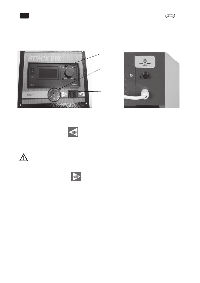
7 OPERATION OF BOILER ATTACK DPX COMBI PELLET
The PROFI PID electronics is located on the front side of the control panel, where the main boiler
switch is located. In the pictures below you can see the basic and safety features of the control
panel.
1. Electronic
regulator
PROFI
2. Manometer
3. Safety
thermostat
4. MODE
switch
The safety thermostat is placed on the rear side of the control board.
Under the PROFI PID electronics there is a WOOD / PELLET mode switch.
Operation in mode WOOD:
The switch will switch to WOOD and the display will show the current boiler temperature, the
controller will be in standby mode.
WARNING: In case the fan is switched on by the START button on the PROFI electronics
and the burner is connected in the boiler, there will be displayed failure of fan turns on
burner.
Operation in mode PELLETS:
The switch switches to the PELLET position and P (see chapter 7.5 Operating modes) is displayed
behind the current boiler temperature value on the PROFI electronics display. In this mode, the
PROFI electronics will not allow you to switch on the exhaust fan by pressing the START button.
The operation of the boiler exhaust fan will be controlled by the burner electronics, depending
on the burner fan operation.
23
Page 25
EN
7.1 OPERATION OF BOILER ATTACK DPX COMBI PELLET – WOOD
MODE
Boiler regulation – wood mode provides high comfort, the possibility of output modulation and
connection to control and regulation units.
The boiler temperature is at the level set by the enduser, to control the flue gas fan rotations.
ATTACK boiler regulator measures the temperature of the water in the boiler all the time and the
value shows on the display with improved controller for flue gas temperature by PID. Based on
this value, the controller controls the fan rotations and pump of central heating.
Technical description of ATTACK PROFI boiler:
Connection
Before turning–on the boiler with the main switcher, connect the controller, fan, circulation
pump and power cords into the appropriate sockets at the rear part of boiler. Boiler temperature
sensor must be placed in the boiler basin. Set the switch to position WOOD.
WARNING! Before connecting the controller to the mains, check that it is properly
grounded and the terminal screws are tightened properly.
ATTENTION: Maximum total output of units connected to the controller can not exceed
700 W.
ATTENTION: For extended function of controller can be connected the module UM–1,
which allows to control start–up of another automatic boiler.
24
Page 26

EN
7.2 ADVANTAGES OF THE REGULATOR
The regulator can control:
1. Rotations of flue gas fan
2. Circuit pump of heating circuits
3. Pump for warming the D.H.W. or pump for warming the accumulation tank (always just one)
4. Starting another, automatic boiler, if the fuel in the boiler burned out
The regulator measures the following:
1. Boiler temperature
2. Flue gas temperature
3. Temperature in the D.H.W. tank or in the accumulation tank (always just one)
4. Room thermostat and thereby it controls the circuit pump
7.3 BASIC DESCRIPTION OF THE REGULATOR
1. main switch
2. icon for D.H.W. temperature
3. icon for temperature of accumulation tank
4. icon for flue gas temperature indication
5. icon for current boiler temperature
6. current boiler temperature (or temperature of D.H.W., flue gas, etc.)
7. sign for boiler operating mode
8. setting the boiler temperature
9. button to enter into the information menu, service menu and confirmation of parameters
10. icon for fan operation
11. operation of the pump for D.H.W. or for accumulation tank warming
12. icon for circuit pump operation
13. icon for enter into the service menu
14. icon indicating overheating or damaged sensors
15. icon indicated that the room thermostat is started
16. button to stop the boiler or to move backwards in menu
17. button to start the boiler or to move forwards in menu
25
Page 27
EN
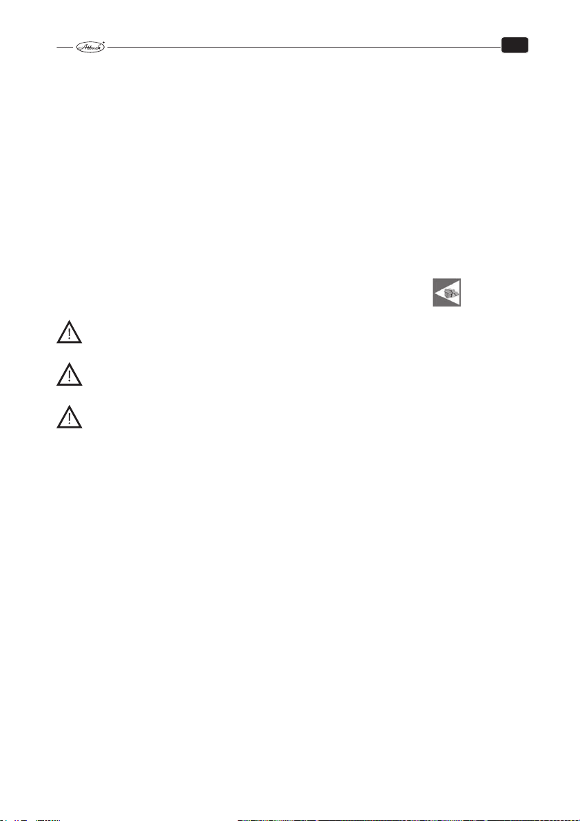
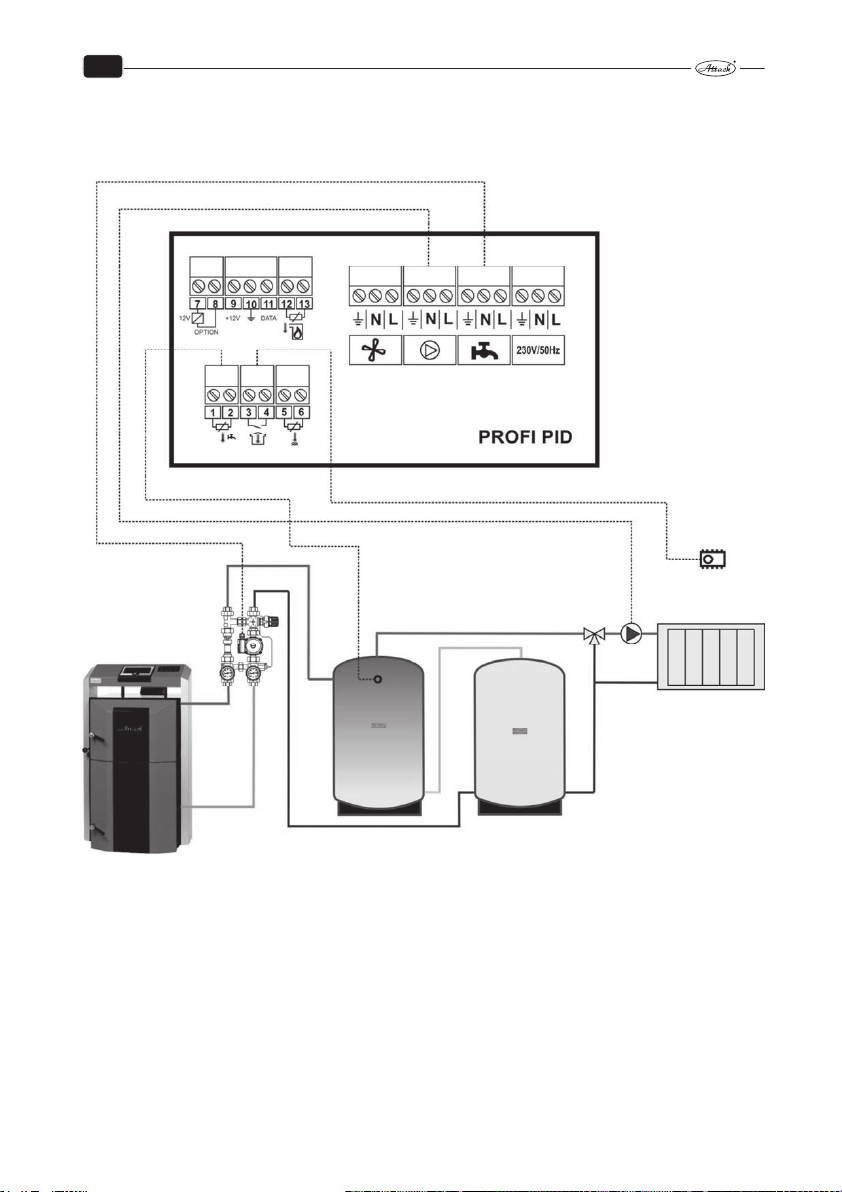
7.4 CONNECTION OF THE REGULATOR BY HYDRAULIC SCHEMES
The regulator can control several types of hydraulic schemes. Parameters in the service menu
must be correctly set adequately to the type of the hydraulic scheme.
* Schemes shows the connection to the pumps and sensors. On the schemes is not showing the
connection to the fan and mains.
Scheme A: Wood gasifying boiler + heating circuit
Parameter setting for the hydraulic scheme A:
ur = ur0
26
Page 28
EN
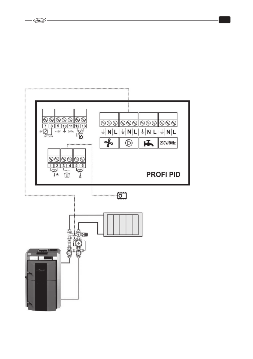
Scheme B: Wood gasifying boiler + heating circuit + warming of D.H.W.
Parameter setting for the hydraulic scheme B:
ur = ur1 – for priority charging of the D.H.W. tank
ur = ur2 – for paralel charging the D.H.W. tank
27
Page 29
EN
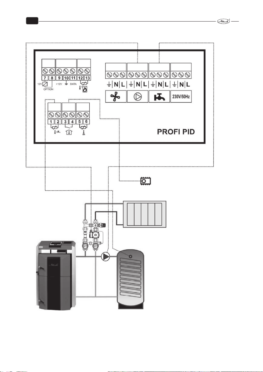
Scheme C: Wood gasifying boiler + heating circuit + warming of accumulation
tank
Parameter setting for the hydraulic scheme C:
ur = ur4
28
Page 30
EN
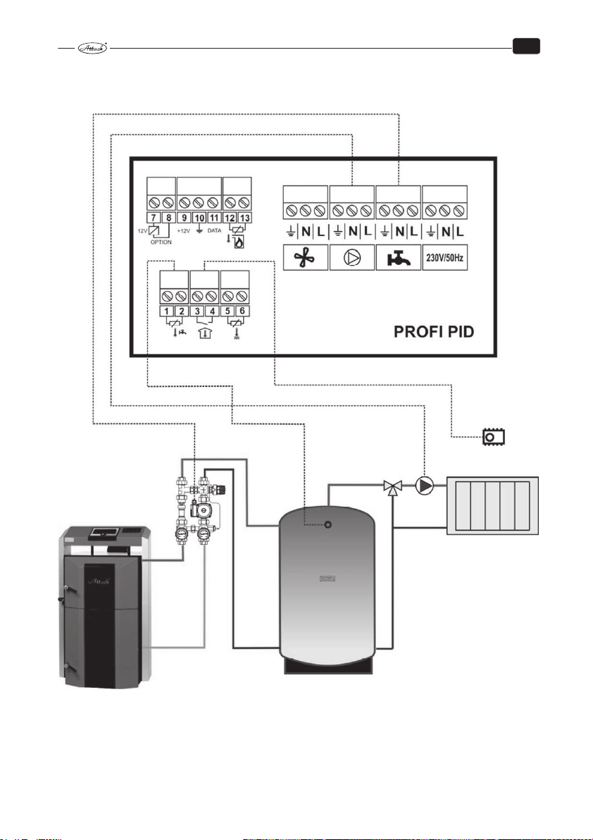
Scheme D: Wood gasifying boiler + heating circuit + warming of accumulation tanks connected in serie
Parameter setting for the hydraulic scheme D:
ur = ur4
29
Page 31

EN
Scheme E: Wood gasifying boiler + heating circuit + warming of combined accumulation tank
Parameter setting for the hydraulic scheme E:
ur = ur4
30
Page 32

EN
7.5 REGULATOR CONTROL AND OPERATING MODES
Turning on the controller is signalized by a brief switching on all the light indicators on display
to enable to check their status. If the regulator gets suddenly disconnected from electricity
mains (e.g. by power failure), it is switched to the last mode used, when the failure occurred. All
the settings made are saved even after the power failure.
The basic setting of the controller is the adjustment of the boiler temperature by the knob. Other
functions are controlled adequately to the service parameters set in the service menu.
The boiler is turned on by pressing the START (17) button that starts the fan. The STOP (16) button switches the boiler off by turning the fan off.
The sign displayed behind the numeric temperature indication (7) is related to the current
mode of the PID PROFI regulator:
[50°-] indicates the stand–by mode
[50 °C] indicates the winter operating mode
[50 °C] indicates the winter operating mode when the boiler temperature is achieved
[50°U] indicates summer operating mode intended only for D.H.W. preparation
[50°u] indicates summer operating mode when the boiler temperature is achieved
[70°d] indicates mode of elimination the legionella bacteria, when the temperature of D.H.W. is
increased to 75 °C
[50°P] indicates that regulator is blocked by pellet burner of the COMBI Pellet boiler
The PROFI PID regulator has an advantage of regulating the flue gas temperature to the required
value. The controller struggles to achieve the adjusted flue gas temperature and after it is
achieved, the required boiler temperature is to be reached. Thereby is the fuel used in the best
way and the high efficiency is achieved.
7.6 SETTING THE USER PARAMETERS
The menu for displaying and setting the user parameters is accessible after short pressing of the
OK button. The „+“ and „−“ buttons are used to browse in settings and parameters. The appropriate parameter selected becomes adjustable by the „OK“ button and starts to flicker. Then it
can be changed by the „+“ and „−“ button and confirmed by „OK“. Some of the parameters are
only informative and they cannot be changed. To exit the menu, confirm the [End] by „OK“ button. After remaining more than 1 minute without the user´s intervention, the controller switches
the display to the basic mode.
31
Page 33

EN
WINTER,
Table 2. User parameters:
Indication Parameter Min Max Step
C 45 Adjusted boiler temperature L65 H90 1 °C –
co C
cu u
u50°
150° Current flue gas temperature
End Exit from user parameters
Operating mode of the circuit pump (‘C’ –
‘–‘ – SUMMER)
Operation of the D.H.W. pump (‘u’ – casual mode,
‘d’ – elimination of legionella bacteria)
Current temperature measured in the accumulation
tank or D.H.W. tank
C –
u d u
[C 45] – Adjusted boiler temperature – this is the value of boiler water temperature the regulator is going to reach while in the WORK mode. It is set by turning the thermostat knob manually (8) and shown briefly on the display (6).
[co C] – WINTER/SUMMER mode – the winter mode is indicated by the ‘C’ letter. Then is the
circuit pump controlled by the room thermostat and distributes the heat into the heating system. The summer mode is indicated by the „–“ sign. Then is the circuit pump out of order and
the heat generated by boiler is only used to heat the D.H.W. tank. If there is not D.H.W. tank in
the system (additional sensor is not connected), it is not possible to select the SUMMER / WINTER
mode.
[cu u] – Mode of D.H.W. tank warming – the regulator enables the casual D.H.W. tank warming
„u“ or the mode to eliminate the legionella bacteria „d“. After the „d“ mode is selected, the temperature of 75 °C is achieved in the D.H.W. tank. When this temperature is achieved, the controller switches into the mode of the casual D.H.W. tank warming „u“. The option of elimination the
legionella bacteria is not available, if the additional outlet and sensor are not set for the D.H.W.
warming.
ATTENTION! Not to get hurt by the hot water, it is recommended to set this mode, when the
D.H.W. is not being used (e.g. during the night).
[u50°] Temperature of additional sensor – this is the value of current temperature of the
D.H.W. tank or of the accumulation tank of the heating system. This temperature is not displayed
in the user menu, if the additional output is not used.
[150°] Flue gas temperature – this value represents the current temperature of flue gas, if the
parameter for flue gas temperature is set in the service parameters.
Prod.
setting
C
32
Page 34

EN
7.7 SETTING THE SERVICE PARAMETERS
By holding the OK button you get into the service menu to the parameter settings (the icon
(13)). The buttons „+“ and „−“ are used to browse in particular parameters. After selecting the
appropriate parameter, it is confirmed by „OK“ button and starts to flicker. To exit the menu,
confirm the [End] by „OK“ button. After remaining for more than 1 minute without the user´s
intervention, the controller switches the display to the basic mode.
Table 3. Service parameters:
SERVISCE MENU (available by holding the OK button)
Display Parameter Min Max Step
Π100 Maximum fan output 1 100 1% 100
n 40 Minimum fan output 1 100 1% 40
Πh 5 Ratio of changing the fan rotations 2 20 1 5
Πr 0 Automatic regulation of changing the fan rotations –, 0 10 1 0
Πt 1 Delay of changing the fan rotations 0 99 1 1
Πn 5 Frequency of exhaust fan blow–through ––, 5 60 1 s 5
Πu 6 Duration of exhaust fan blow–through 1 99 1 min 6
Πd3 Duration of manual fan operation for 100% ––, 1 99 1 min 3
r100 Fan output by ignition 1 100 1 % 100
rh 5 Hysteresis of boiler stop by ignition 1 45 1 °C 5
P 30 Temperature to start the circuit pump
Ph 2 Hysteresis of circuit pump 1 40 1 °C 2
Pc –– Interval of unlock function of circuit pump ––, 1 99 1 min 2
Ur0 Operation of additional output 0 4 1 0
u30 Operating temperature of D.H.W. tank or accumulation tank 30 60 1 °C 30
uh 5 Hysteresis of D.H.W. tank of accumulation tank 1 30 1 °C 5
uP 5 Boiler temperature increase by D.H.W. warming 1 20 1 °C 5
L65 Minimum boiler temperature 30 65 1 °C 65
H 85 Maximum boiler temperature 80 95 1 °C 85
h 2 Boiler temperature hysteresis 1 10 1 °C 2
A 99 Temperature of boiler overheating 90 99 1 °C 99
Fd60 Duration of boiler stop by ignition and fuel shortage ––, 1
Fb30 Duration of boiler stop by flue shortage and burn–down ––, 1
Ar 0 Control of multifunctional additional output 0 1 1 0
c 240 Adjusted flue gas temperature –0,5 250 1 °C 240
c h5 Flue gas temperature hysteresis 1 99 1 °C 5
c t 5 Time constant of stabilization the flue gas temperature 1 99 1 min 5
c F10 Blower speed jump while stabilizing flue gas temperature 1 20 1 °C 10
c 90 Flue gas temperature by fuel shortage 30 150 1 °C 90
c 300 Maximum flue gas temperature 250 400 1 °C 300
Prod Reset of production settings
outΠ Test of fan relay outΠ out1
outP Test of circuit pump relay outP out2
outu Test of relay of optional pump outu out3
outr Test of additional output outr out4
End Exit to main menu
––,
70 1 °C 30
20
99–
4h
99–
4h
Prod.
set.
1 min 60
1 min 30
33
Page 35

EN
7.8 DESCRIPTION OF PARAMETERS
[Π100] Maximum fan output – the highest fan output possible
[n 40] Minimum fan output – the lowest fan output possible
[Πh 5] Ratio of changing the fan rotations – this parameter influences the fan rotations, if the
adjusted boiler temperature is going to be achieved in a short time. For example, if the value 4 is
set, the fan will work at full output [Π100] (if the function of flue gas temperature control is not
active), up to 4 degrees before achieving the required boiler temperature. Then, by every increase of the boiler temperature for 1 °C, the fan rotations are gradually decreased until the minimum fan output is reached [n 40].
[Πr 0] Automatic regulation of changing the fan rotations – the fan rotations are increased /
decreased by setting this parameter within the range of 0 – 10 to ensure the required boiler
temperature. If this parameter is set to „– –“, the rotations are not controlled and the fan works at
full output according to the parameter [Π100]. Setting the parameter within the range of 0 – 10
relates to the time period (in minutes), during which are the fan rotations gradually increased
from the parameter of the minimum fan rotations [n 40] up to the parameter [r 100]. This ensures the fluent heat–up of boiler.
[Πn 5] Frequency of exhaust fan blow–through – this frequency defines, how often the fan is
started to the full output [Π100] to take the flue gas out from the boiler, if the fan was stopped
due to the boiler temperature achieved.
[Πu 6] Duration of exhaust fan blow–through – during this period must the fan exhaust the
flue gas following the parameter [Πn 5].
[r 100] Fan output by ignition – this parameter defines the fan output by boiler heat–up. If the
parameter " Πr " is set to [Πr 0], then this parameter is not available.
[rh 5] Hysteresis of boiler stop by ignition – defines, how many degrees before reaching the
required boiler temperature will be the heat–up phase finished or (if the flue gas temperature
sensor is connected), how many degrees before reaching the required flue gas temperature are
relevant to stop the heat–up phase. After deactivation of the heat–up phase there is a casual
operating mode.
[P 30] Temperature to start the circuit pump – if there is not D.H.W. tank in the system [ur 0] or
it is in the mode [ur 2], then the parameter defines the boiler temperature for starting the circuit
pump of the heating system. If the parameter is set to „– –“, then too low temperature does not
influence the operation of the circuit pump. Anyway, the pump is always started, when the boiler temperature exceeds the parameter [H 85] of the maximum boiler temperature.
If there is accumulation tank in the system (parameter [ur 4]), then this parameter defines the
temperature measured in the accumulation tank by which is the circuit pump of the heating
system started.
[Ph 2] Hysteresis of circuit pump – defines the temperature difference under which must the
boiler temperature or temperature in the accumulation tank decrease in comparison with the
temperature defined by the parameter [P 30] to stop the circuit pump.
[Pc ––] Interval of unlock function of circuit pump –when controller is in the stand–by mode
or the room thermostat is disconnected, the circuit pump is started for 30 seconds after each [Pc
––] minutes to prevent the pump blockage caused by its inactivity. The unlock pump function is
not active, when the Pc is set to „– –“.
34
Page 36

EN
[ur 0] Operation of the additional output – this parameter defines the operating mode of the
additional output (pump for D.H.W. tank or accumulation tank warming).
[ur 0] Additional output without function – defines that the additional output and pump are
not connected and the additional output is not used in this case.
[ur 1] Priority D.H.W. tank warming – by this setting is the pump for D.H.W. tank warming
connected to the additional output and the sensor of D.H.W. is connected to the additional inlet.
Then, if the temperature in the D.H.W. tank decreases under the value of hysteresis
[uh 5] from the temperature adjusted [u 60], the pump of D.H.W. tank warming is started. After
the temperature in the D.H.W. tank reaches the set value [u 60], the pump is stopped. The pump
is also stopped, when the temperature in boiler is lower than the temperature in D.H.W. tank.
The [ur 1] mode means that the D.H.W. warming has priority, i.e. the pump of the heating circuit
is started after the D.H.W. is prepared.
[ur 2] Parallel charging the D.H.W. tank – similar principle as by the [ur 1], just the D.H.W. is
prepared by the parallel operation of the circuit pump of the heating circuit.
[ur 3] Unused
[ur 4] Charging the accumulation tank – due to this setting is the additional output used as
a pump to heat the accumulation tank and the additional sensor measures its temperature.
When the temperature in the boiler exceeds the hysteresis [uh 5] over the current temperature
of accumulation tank, the pump for charging is started. The pump is stopped, when the temperature in the boiler is same or lower than the temperature in the accumulation tank, or when the
temperature in boiler decreases under the minimum boiler temperature defined by the parameter [L 65].
[u 30] Operating temperature of the D.H.W. tank or accumulation tank – temperature to
control the additional output [ur ].
[uh 5] Hysteresis of the D.H.W. tank or accumulation – this parameter defines hysteresis of
the additional output [ur ].
[uP 5] Boiler temperature increase by D.H.W. preparation – this parameter is relevant, when
the additional output works under the mode of D.H.W. tank charging. It defines, for how many
degrees will the adjusted boiler temperature be higher than parameter [u 50] during the D.H.W.
tank warming.
[L 65] Minimum boiler temperature – defines the minimum boiler temperature that can be set
by a knob.
[H 85] Maximum boiler temperature – defines the maximum boiler temperature that can be
set by a knob.
[h 2] Hysteresis of boiler temperature – defines the difference between the adjusted and the
current boiler temperature for which must the boiler temperature decrease to start the controller again after the adjusted boiler temperature is achieved.
[A 99] Temperature of boiler overheating – defines the value of boiler temperature to activate
the alarm of the boiler overheating.
[Fd60] Duration of boiler stop by ignition and fuel shortage – this parameter defines the
maximum time between starting the controller by the START button and achieving the control-
35
Page 37

EN
ler´s operating mode (reaching the flue gas temperature of [c 90]). If the temperature of [c 90] is
not reached during the heating up, the fan is stopped and the alarm FUEL (fuel shortage) is displayed.
[Fb30] Duration of boiler stop by flue shortage and burn–down – the fuel amount test is activated in the operating mode, when the flue gas temperature decreases under the parameter [c
90] or (if the flue gas sensor is not connected) when the boiler temperature decreases under the
adjusted parameter [L 45]. If the temperature does not exceed the necessary limit during this
period, the controller displays FUEL alarm.
[Ar 0] Operation of multifunction additional output – the controller is equipped with an additional multifunctional outputs compatible with the options listed below (to control these options is necessary to use an additional module UM – 1):
• [Ar 0] parameter – indicates start of the automatic boiler (e.g. gas or pellet boiler). When the
controller is started and the boiler generates heat, the automatic boiler is stopped. Operation
of the automatic boiler is blocked by the controller in the operating mode. The automatic
boiler is started by controller, when the fuel is burned down in the boiler and the FUEL alarm
is displayed.
• [Ar 1] parameter – indicates that the additional multifunctional output will be used for error
messages like boiler sensor failure, overheating or fuel shortage.
[c 240] Adjusted flue gas temperature – the controller will struggle to reach and to keep this
value. The flue gas temperature sensor is turned off, if this parameter is set to „– –“.
[c h5] Hysteresis of flue gas temperature – defines the difference for which must the flue gas
temperature decrease to increase the fan rotations.
[c t 5] Time constant of stabilization the flue gas temperature – defines the period of adjusting the fan rotations during stabilization of the flue gas temperature. If the flue gas temperature
exceeds the value given by the parameter [c 240], the controller starts to decrease the fan rotations gradually, until the flue gas temperature decreases to the adjusted value. If the flue gas
temperature decreases to the value of flue gas temperature hysteresis, the controller starts to
increase the fan rotations gradually.
[c F10] Blower speed jump while stabilizing exhaust gas temperature – defines the change
of rotations to achieve the adjusted flue gas temperature.
[c 90] Flue gas temperature by fuel shortage – the message „FUEL“ for fuel shortage is displayed after the flue gas temperature decreases under this value.
Testing the regulator outputs:
It is possible to make a check to test the correct functionality of the regulator and devices connected. The correct function of fan is tested by selecting the [outΠ] on display and holding the
„OK“ button. Test of the circuit pump is done by selecting the [outP]. Select the [outu] to start
the additional output and [outr] for multifunctional additional output.
Reset of the regulator´s pruduction settings:
There is a possibility to reset the production settings of the regulator by selecting the [Prod] in
the service menu and confirming by „OK“ button. Then is the regulator set to the values given in
the Table 3.
Exit from service menu:
Select the [End] on display and press the „OK“ button to exit from service menu.
36
Page 38

EN
7.9 ERROR MESSAGES
The connection of all sensors of the regulator is permanently monitored. If the regulator detects
that some of the sensors is not connected, the error messages are displayed. Messages about the
boiler overheating or fuel shortage are also displayed.
7.9.1 ERROR MESSAGES DISPLAYED
[FUEL] – is displayed, when there is not enough fuel in the boiler. The sufficient amount of fuel is
defined by the parameter c90, where the figure 90 is related to the adjusted value 90 °C. Then, if
the flue gas temperature decreases under this adjusted value within the time Fb30 (time of boiler stop by fuel shortage), the regulator displays the [FUEL] message. To start the boiler again, it is
necessary to remove the message by the STOP button and then to press the START.
[HOT] – is displayed, when the flue gas temperature exceeds the maximum permitted value set
by the parameter c300 (means 300 °C). The ventilator is stopped in this case. After the temperature decreases under the adjusted flue gas temperature, the ventilator is started again.
[E 1] – is displayed, when the boiler temperature sensor fails or when it is not connected. In such
case is the regulator taking actions to ensure the safety of the boiler – the fan is stopped (if it is
currently in operation) and the circuit pump is started for eventual safe boiler cooling. After the
cause of error is removed, the error message can be erased by the STOP button.
[E 2] – is displayed, when the boiler temperature exceeds the boiler overheating temperature
A99. The regulator stops the flue gas fan and starts the circuit pump. The error message can be
removed by the STOP button after the boiler temperature decreases to the safe value.
[E 8] – is displayed, when the additional sensor fails (in the D.H.W. tank or accumulation tank). If
this sensor works for the D.H.W. tank, the warming is blocked. If the sensor works for the accumulation tank, the pump will be permanently working. This error message cannot be removed
by the STOP button. It is automatically erased after the sensor failure is repaired.
[E128] – is displayed, when the flue gas temperature sensor fails. In this case is the boiler control
switched to regulate according to the boiler temperature. The error message is erased automatically after the fault of the flue gas temperature sensor is solved.
[E 3] If several failures occur in one moment, their total is displayed. In such case it is necessary to
check the functionality of all sensors.
37
Page 39
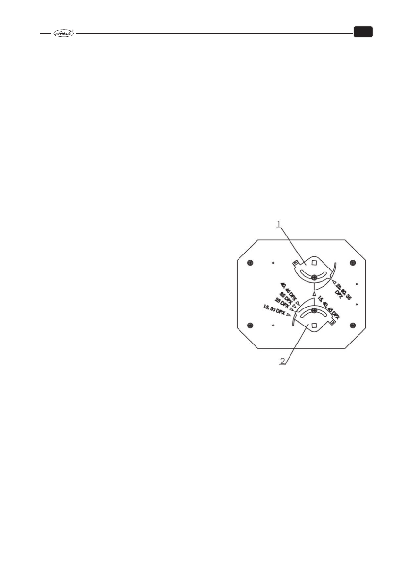
EN
7.10 DISASSEMBLY OF THE REGULATOR
If it is necessary to disassemble the regulator, do the following:
• turn the main switch off
• disconnect the boiler from electricity mains
• demount the regulator
• demount the connectors from the regulator
7.11 TECHNICAL SPECIFICATION OF THE REGULATOR
Power supply 230 V ±10 %, 50 Hz
Input (not including the ventilator and pumps) < 4 VA
±
Range of measuring the boiler temperature −9 – 109 °C
Range of measuring the flue gas temperature −30 – 500 °C
Max. input of devices connected to the regulator 2 A/230 V
1 °C
±
1 °C
7.12 OUTPUT CONTROL OF ATTACK DPX COMBI PELLET
Adjustment of burning in the boiler
The burning is adjusted by the primary and secondary
regulation flap. Producer sets the boilers to the optimum conditions of burning with reference to the emissions and flue gas temperature. Only the service staff
trained by producer can make the adjustment.
Optimum setting of the regulation flaps – wood
mode (Primary/Secondary):
DPX25CP – 50/40
DPX30CP – 50/25
DPX35CP – 50/50
DPX40CP – 100/60
DPX45CP – 100/60
7.13 OPERATION WITH PERMANENT BURNING
It is possible to keep the permanent burning, i.e. the fire in the boiler for the whole night without
need to heat up during the day, but only in the winter period. This method of operation reduces
the life of the boiler.
For the operation with permanent burning it is necessary to prepare the boiler in the following way:
• Lay some bigger wood logs (4 – 6 pcs.) on a glowing layer of fuel
• Close the mixing valve partly – temperature of water in the boiler achieves 80 – 90 °C
• The regulation flap controlled by thermal regulator is automatically closed and the fan is
stopped.
After the boiler is prepared in this way, the burning is kept for more than 12 hours. When
the boiler is in the operation of permanent burning, the water temperature must be
80 – 90 °C.
38
Page 40
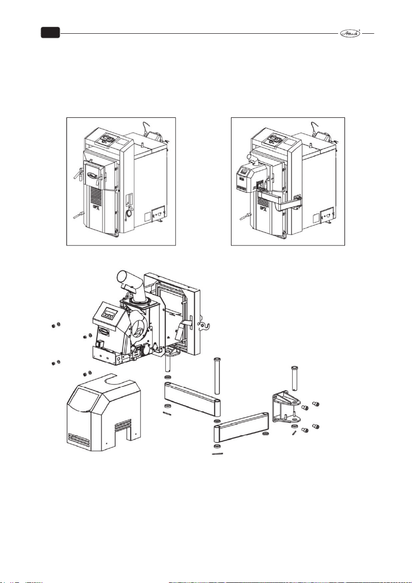
EN
8 BURNER ASSEMBLY TO THE BOILER
The boiler DPX COMBI Pellet – mode wood has mounted on the upper loading door cover – cover of the upper loading door. If you want to go for automatic pellet combustion, you have to
remove this plug by simply movement up and down with the two handles and put it away from
the boiler. After that it is necessary to mounted the pantograph, burner door and burner on the
boiler.
Steps of burner assembly to the boiler:
1. For simple manipulation and operation during operation of the burner, the burner together
with the burner door will be placed on the movable arms of pantograph. For their installation is necessary to mount the pantograph console in the hole in the right leg of boiler. Console will be fixed with four screws M12 × 20 with cylindric head and internal hexagonal
screwdriver.
2. Then it is easy to put together arms of pantograph by pins, cotter and mats. By mounting the
short arm of the pantograph is required to put bronze mat between the bottom of arm and
39
Page 41
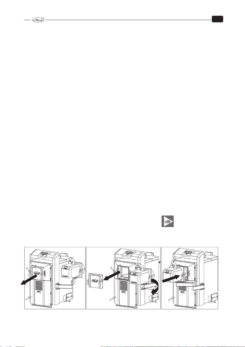
EN
console, as well the mat on the bottom part of console. Pin is necessary to secure with the
cotter.
3. The same process is applyed by installation of the long arm of the pantograph, where we put
the bronze mat between short and long arm of pantograph, mat on the bottom part of short
arm and pin is secured by cotter.
4. Burner door are supplied with console and pin, in one piece, for simple installation to the
arm of the pantograph. Between the console door with pin and long pantograph arm put
again bronze mat, other mat under the bottom part of the long arm and pin is secured by
cotter.
5. Secure the burner door on movable arm to upper door of the boiler by simple movement of
two handles. It is the same how it was by demounting of the plug.
6. Burner with flange pushed onto the welded screws on the burner door and secure with flat
mat 8,4 and nuts M8.
7. Hanging cable for burner connection to the boiler to attach as well as the boiler temperature
sensor to the arm of the pantograph by supplied plastic tapes from the bottom of the pantograph arms. Then put the cover on the burner.
9 OPERATION OF BOILER ATTACK DPX COMBI PELLET –
PELLETS MODE
Pellet burners ATTACK PELLET BURNER Automatic 8 – 30 kW and 15 – 50 kW built into the boiler,
model ATTACK DPX COMBI Pellet 25, 30, 35, 40, 45, 50 are modern burners which are saving environment with combustion technology, offer to end users the advantage of low operating costs
and offer also comfort comparable with the gas boilers when is boiler operating with pellets,
automatic combustion.
For the boiler operation with pellets is necessary to remove the plug of upper loading door.
Block off two handles and put the plug away from the boiler. With the pantograph simply bring
burner to the upper door of the boiler, insert it through the door into the boiler and block the
burner with two handles. By blocking the burner to the door of the boiler, needs to make pressure in a straight line. The burner door needs to seal with the boiler door.
Inserting and securing the burner in the boiler door, burner is ready for operation. On the control panel you must switch the mode switch to PELLETS position.
At the time when the burner is out of the boiler door it is not possible to operate or change the
settings in the menu.
40
Page 42

EN
WARNING! After inserting the burner into the boiler DPX it is always necessary to
close the flaps of primary and secondary air. Otherwise the flue gas produce by the
burner can exit through openings of primary and secondary air. This can be the
cause of fire!
Setting of DPX boiler for wood combustion (primary and secondary flap open).
Setting of DPX boiler for pellets combustion (primary and secondary flap closed).
41
Page 43

EN
The burners ATTACK PELLET BURNER Automatic works on basis of the fuel feeding by the
principle of falling, when the pellets fall by from the pellet feeder through the inlet hose and the
inlet tube on the grate, where they are burned.
The burners have an electrical ignition that automatically lights the pellets fallen on the grate.
Starting the burner is controlled by adjusting the burner and boiler temperature or room thermostat, if it is connected. Start and stop temperature can be set in menu with buttons on the
controll panel of the burner. Information about actual operation data is given on display.
The burners have an own self–cleaning mechanism of the grate. When the thermostat reaches
the adjusted off–temperature, the burn–out cycle begins and afterwards, the grate moves out to
be cleaned by scraping. This enables longer time of use, without need to remove the burner
from the boiler. Convectional parts of the boiler have to be cleaned in regular intervals to keep
the high efficiency of heating.
The boiler can be used only moulded wood pellets without additional materials and with
following parameters:
Approved fuel specification:
Measured weight: 600 – 750 kg/m
Heat value: 4,7 – 5,0 kWh/kg
Size/diameter: 6 mm
Size/length: Attention! Max. 35 mm
Moisture max.: 12 %
Ash content: 0,5 – 1 %
Dust content: max. 3 %
Ash smoulder temperature: min. 1 100 °C
Standards : DIN 51 731 – HP 5, DIN Plus, or EN 14961–2 – A1
Regulation of the pellet dosing
Before starting–up the burner, it is necessary to set the pellet supply through the parameter of
the „Stoker Adj.“ in the Advanced menu. Thermostat cannot start the heating while the settings
are being made. Firstly, set the parameter of the „heat value“ to the value given by your pellet
supplier. If the supplier gives 4,8 kWh/kg, set the parameter to 48, etc.
Now, put the plastic bag around the opening of the pellet feeder. Then, confirm by the „S“ button and keep the instructions. Weigh the pellets fallen into the plastic bag, put their weight in
gramms via the „+/−“ buttons and press the „S“ to save the values. This setting has to be done
within 15 minutes, otherwise the burner switches to the stand–by mode. Weigh the pellets very
exactly!
After setting of the above mentioned parameters, the control system automatically sets all the
parameters relative to the pellet feeding.
3
42
Page 44

EN
9.1 ATTACK PELLET BURNER AUTOMATIC 8–30 KW
The burner is set in production to the output range of 14 – 30 kW and three degrees of output:
1 (14 kW), 2 (22 kW) and 3 (30 kW). The selected output degree is dipslayed during the operation.
It is possible to set the output via the menu buttons of the burner and the information on display. The range of output can be changed in two levels – from 8 to 12 kW and from 14 to 30 kW –
according to this there are three degrees of output from 8 to 12 kW or from 14 to 30 kW in the
advanced menu.
Basic description of the
burner:
1 – combustion chamber
2 – air chamber
3 – ventilator
4 – tube of fuel inlet
5 – main electronics
6 – display with control panel
7 – gear of grate cleaning
8 – electrical heting coil
9 – cover
10 – photocell
The burner is formed by pellets combustion chamber, air chamber with ventilator and control
units with the gear of grate cleaning. The burner is designed for end user with the most comfort,
cleaning aspect and total spent time with the boiler. The base of the burner is combustion
chamber, which is made from welded high quality stainless steel with a thickness of 3 mm,
which guarantees long lifetime.
The cover of the burner presented burner design. Surface conditioning of cover is realized with
dust technology.
The burner is delivered in a paper box filled with polysthyrene to improve stability. If the box is
damaged, check the burner for possible damage by transport. Claim of the damage by transport
has to be registered by a spediteur.
The paper box ought contain the following items:
• 1 pc. ATTACK PELLET BURNER Automatic 8–30 kW
• 1 pc. plug of upper loading chamber
• 1 pc. inlet tube with emergency thermostat of back–burning
• 1 pc. pantograph
• 1 pc. burner door
Note: Boiler temperature sensor for burner has been by factory installed in the boiler. This sensor needs
to be connected to the connector of burner electronics, signed TS2, after burner installation.
43
Page 45

EN
9.2 ATTACK PELLET BURNER AUTOMATIC 15–50 KW
The burner is set in production to the output range of three degrees of output: 1 (15 kW), 2 (32
kW) and 3 (50 kW). These is possible to set between 15 – 50 kW in burner menu. The selected
power level is showen on the display during the operation.
Basic description of the burner
1 – cover
2 – burner basket
3 – main electronics
4 – display with control panel
5 – ventilator
6 – gear of grate cleaning
7 – air chamber
8 – tube of fuel inlete with emergency thermostat of back–burning
9 – fireproof concrete roof
10 – combustion chamber
11– line cord
The burner is formed by pellets combustion chamber with fireproof concrete roof, air chamber
with ventilator and control units with the gear of grate cleaning. The burner is designed for end
user with the most comfort, cleaning aspect and total spent time with the boiler. The base of the
burner is combustion chamber, which is made from welded high quality stainless steel with a
thickness of 4 mm, which guarantees long lifetime.
The cover of the burner presented burner design. Surface conditioning of cover is realized with
dust technology.
The burner is delivered in a paper box filled with polysthyrene to improve stability. If the box is
damaged, check the burner for possible damage by transport. Claim of the damage by transport
has to be registered by a spediteur.
44
Page 46

EN
The paper box ought contain the following items:
• 1 pc. ATTACK PELLET BURNER Automatic 15 – 50 kW
• 1 pc. plug of upper loading chamber
• 1 pc. inlet tube with emergency thermostat of back–burning
• 1 pc. fireproof concrete roof
• 1 pc. pantograph
• 1 pc. burner door
Note: Boiler temperature sensor for burner has been by factory installed in the boiler. This sensor needs
to be connected to the connector of burner electronics, signed TS2, after burner installation.
9.3 BURNERS DIMENSIONS
ATTACK PELLET BURNER Automatic 8 – 30 kW
ATTACK PELLET BURNER Automatic 15 – 50 kW
45
Page 47

EN
9.4 DESCRIPTION OF FUNCTION
ATTENTION: The burner is controlled on the basis of the boiler temperature sensor (in
the burner menu must be set in the advanced settings THERMOSTAT to the "Combination") or room thermostat, if is connected to the terminals TP under the electrical scheme.
It is possible to choose boiler temperature and hysteresis in burner menu. The burner will
try to achieve the set temperature and according to hysteresis the burner will be turned
on.
9.4.1 NORMAL START–UP IN STAND–BY MODE OF BURNER
When the thermostat gives instruction to the burner, the ventilator starts and the photocell controls the fire. If there is no fire, then comes the instruction to blow the burner through. Afterwards, pellets start to fall into the burner within the period stated by the control system and the
ignition is activated. After the phase of fuel feeding for ignition is finished, the control system
waits for signalization of fire from the photocell. When the photocell recognizes the fire, small
amounts of pellets fall within the transition period. Duration of this depends on the output level
set on the burner. Pellet supply is gradually increased, until the necessary fuel amount for the
required output is achieved. This amount is further delivered into the burner, until the operation
thermostat gives instruction to stop.
This signal stops the pellet inlet, while ventilator continues to supply the air into the burner.
When the photocell recognizes burn–out of pellets, the blow–through of the burner begins.
According to the adjusted delay, the burner is cleaned after the fuel burns out – the grate moves
out towards the scraper and the ash with the unburned elements falls through the front wall of
the burner´s bottom into the ashpan. After the grate slides back, the burner waits for the new
signal from thermostat.
CAUTION: : The unit for the grate moving is very strong and it might cause a threat. Nev-
er put any body parts or foreign articles into the burner, while it is working.
9.4.2 BURNER START–UP, WHEN THERE IS STILL FIRE IN THE BURNER
If the photocell recognizes the fire during the beginning phase (e.g. after the short time current
shortage), the control system directly begins the transition–phase and the pellet burner continues to operate as by normal start. (see above)
9.4.3 BURNER START–UP, WHEN THE CONTROL SYSTEM DOES NOT RECOG-
NIZE THE FIRE
The normal start–up process follows, also when the control system does not receive the fire signal. The system starts shortly after repeated ignition process, which increases the ignition
amount in the combustion chamber and heating of spiral continues until the photocell does not
detect the presence of flame. These parameters are adjustable only by the trained person in service menu. If the second trial fails, all functions are turned off and the alarm is activated. This
alarm is indicated on display.
46
Page 48
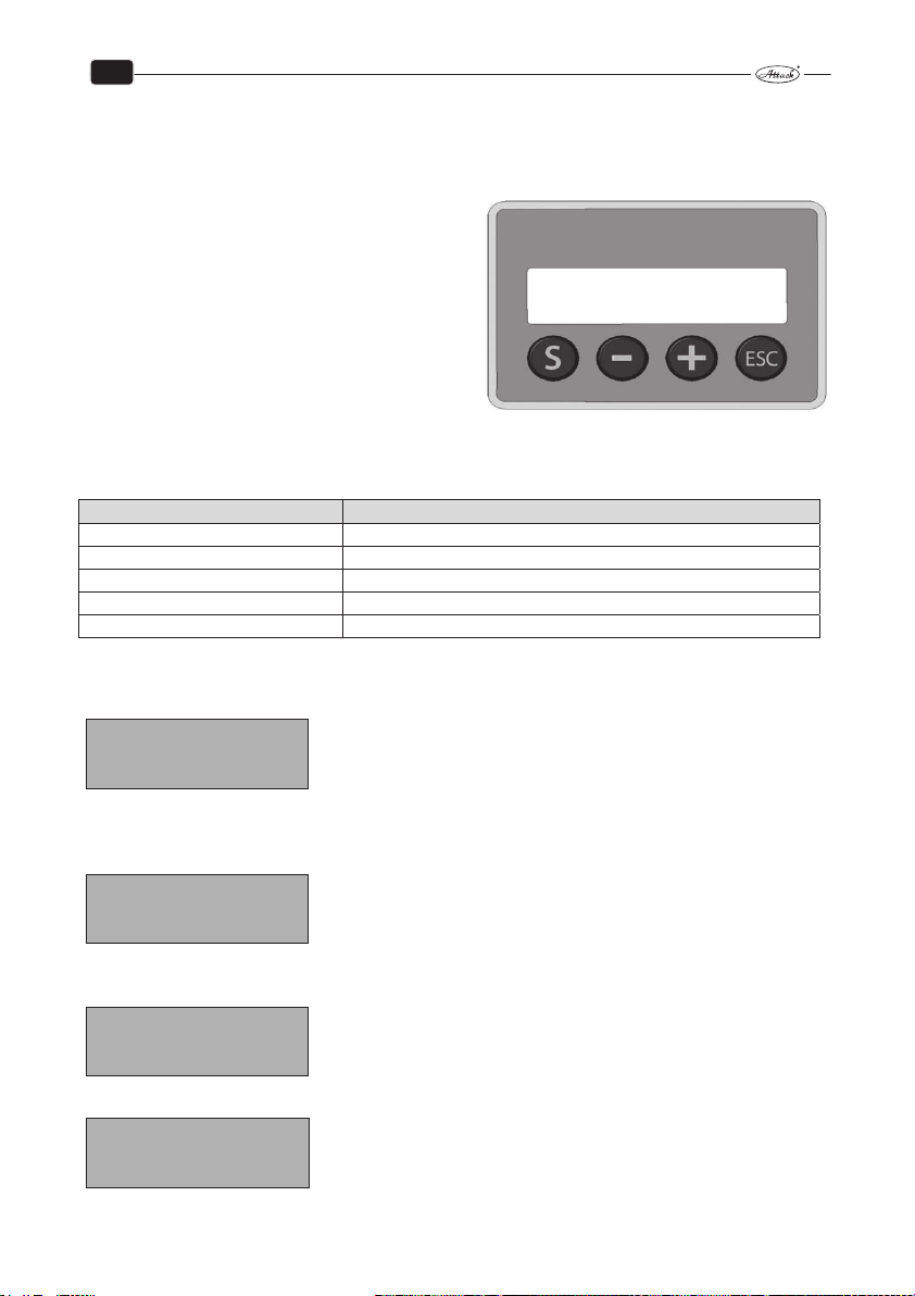
EN
9.5 MENU AND FUNCTIONS
Functions of the burner are set via the menu buttons under the display. (see also options of settings under the Production settings, below).
How to change settings of the pellet burner:
„S“ – Menu/Enter: For activation of furtherrecords
and ENTER/SAVE of the changes.
„−“: For comeback in menu and reduction of the ad-
justable values.
„+“: For advance in menu and increasing of adjustable
values.
„ESC“– Exit/Escape: For exit from menu without sav-
ing the new values.
Values that can be set by the user are given in the following schedule:
MENU Explanation
EFFECT ADJ. Required output degree (1, 2 or 3)
PELLET–TRIM Setting of the pellet ration supplied
LOG Record of faults for control purposes
FINAL COMBUST. Instruction to burner for burn–out
MENU/ ADVANCED Access into service menu via code
9.5.1 INDICATIONS ON DISPLAY
Standby mode
PAUS.
OFF FC: 0 %
Temperature sensor or thermostat starts.
Step 1: Test blow–through
TEST BLOWING
ON FC: ? %
Step 2: Fuel ration for heating up
IGNITION 1
ON FC: ? %
Step 3: Transition phase
TRANS. PHASE ??kW
ON FC: ? %
Nothing in the burner is started, burner waits for the signal from
thermostat to start.
The fan starts to operate and when the photocell recognizes the
value (%), the program continues.
The fuel ration for heating up is supplied into the burner and program waits for the „fire“ signal from photocell.
The transition phase begins, when the photocell and the control
system recognize the fire. Small, gradually increased amounts of
pellets are feeded into the burner, until the required pellet ration
is achieved.
47
Page 49
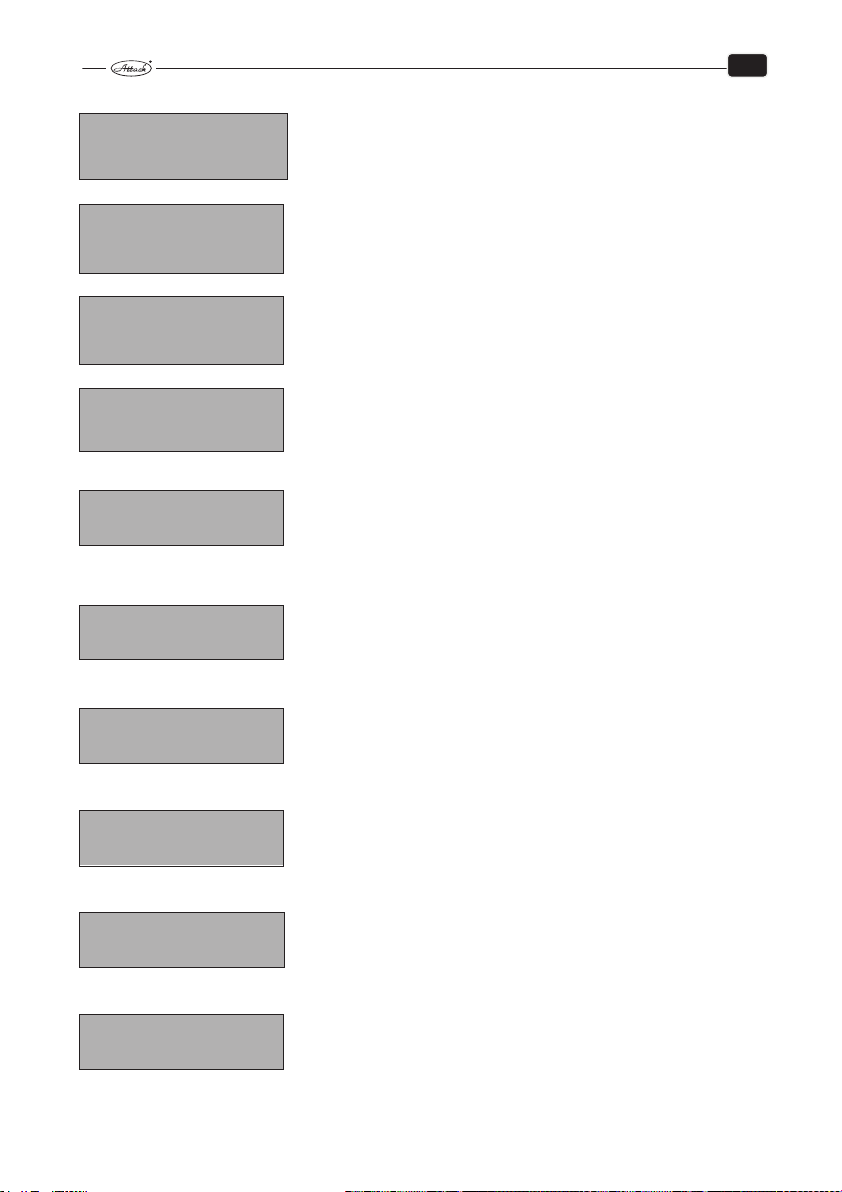
Step 4: Combustion
COMBUST. ??KW
ON FC: ? %
The combustion phase runs, until it is interrupted by the thermostat.
Step 5: Burn–out
The thermostat interrupted the combustion phase and the burner
FINAL–COMBUST.
OFF FC: ? %
begins the phase of burning–out.
Step 6: Cleaning
The grate moves out and when it is out completely, the fan runs at
SCRAPING
OFF FC: 0 %
full rotations, until the grate moves back.
Step 7 Ash removing
STOKERTIME
OFF FC: 0 %
Gear of ash removing is started after determined period (e.g. 6
hours) and it works within the stated time (e.g. within 3 min).
Step 8: Return into standby mode.
PAUSE
OFF FC: 0 %
9.5.2 MENU INDICATIONS
PAUS.
OFF FC: 0 %
Press the”S” button.
EFFECT LEVEL
ENTER EXIT
Press the ”+” button.
PELLET–TRIM
ENTER EXIT
Press the ”+”button.
FINAL–COMBUST
ENTER EXIT
Press the ”+”button.
LOG
ENTER EXIT
The burner is in the standby mode.
Here you can change the burner output. Level 1 = 15 kW, 2 = 32
kW, 3 = 50 kW.
The range and the levels of output are adjustable in the advanced
menu.
Here you can set the pellet amount to be supplied. It is not necessary, if the correct pellet weight was set in the Pellet dosing in the
service menu.
If you wish to clean the burner or to interrupt the operation from
other reasons, press the „S“ button, and the burn–down mode
begins. To restart the burner after ash removing, press the „S“
button.
This internal setting can be helpful by troubleshooting, if the
burner stops and the alarm is activated. The last 10 different error
codes are recorded. For more information about the error codes,
see the „Troubleshooting“.
EN
48
Page 50
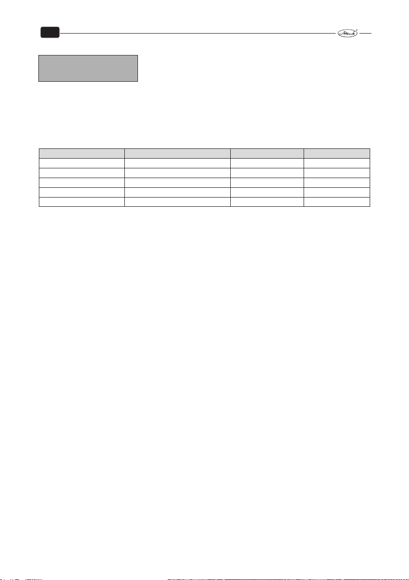
EN
Entry code
Press the ”+”button.
MENU/ADVANCED
ENTER EXIT
To enter into the advanced menu you need password (code) and
it is necessary to know the program functions of the burner.
9.6 PRODUCTION SETTINGS
9.6.1 ATTACK PELLET BURNER AUTOMATIC 8–30 KW
Basic menu:
Menu Production settings Range Adjustable
Effect level 2 = 22 kW 1, 2, 3 8 – 30 kW
Pellet–trim 95 % 50 – 200 % 50 – 200 %
Final combustion Yes Yes/No 10 – 600 sec.
Log View faults N/Y N/Y
Advanced menu View random number
+ 5 N/Y
49
Page 51
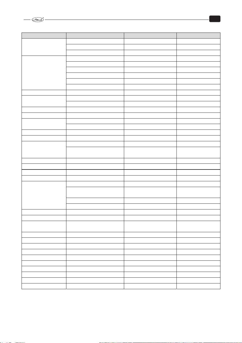
EN
Yes/No
Before ig./after
60 kWh/kg
Auto/Manual
Advanced menu:
MENU Parameter Range Adjustable
Effect adj.
Ignition
Test – blow time Delay 10 – 100 s 15 s
Transition phase
Transition pellet–trim Transition phase trim 10 – 100 % 15 %
Clean–blow time Clean–blow time 10 – 900 s 200
Ash auger
Max. comb. time Max. comb. time 30 – 1 080 min 60 min
Anti–cycling Anti–cycling 0 – 60 min 10 min
Modulation
Photocell Photocell 25 – 80 % 35 %
Thermostat Thermostat EXT; SENS; COMBI COMBI
Cleaning
Pump control Pump active? Inactiv/Automatic
Pump safety temperature
Language Language EN, SK, CZ, HU, ES, … SK
Effect span 0 = 8 – 12, 1 =14 – 30 0, 1 1
Stoker adj. Heat amount 45 –
Fan factor Fan 10 – 500 96
Stokertime hour
Menu/Test
Menu/Setting See Advanced
Menu / Log Save the error codes See Advanced
Output 1 [kW] 8 –12 14
Output 2 [kW] 14 – 22 22
Output 3 [kW] 22 – 30 30
Delay 0 – 3 1
Feeding time 1 30 – 300 % 95%
Ignition time 1 10 – 600 s 480 s
Feeding time 2 10 – 300 % 45%
Ignition time 2 10 – 600 s 240 s
Fan speed 800 – 2 800 1 500
Transition phase time 0 –14 20 – 460 s 240 s
Transition phase time 0 – 30 260 – 500 s 480 s
Ash auger time 0 – 10 min 3 min
Run interval 1 – 200 h 6 h
Power modulation 0 – 100 % 70 %
Temperature modulation
range
Temperature of turn–off 15 – 99 80°C
Hysteresis 1 – 75 10°C
Activate?
Grate cleaning?
Delay? 0 – 60 min 1 min
Number of cleaning 1 – 5 1
Delay 0 – 60 10 min
Pump safety temperature 70 – 90 90°C
Fan 1 gain 1 – 100 10
Fan 1 interval 1 – 50 1
1 – 100 deg 10 deg
Yes
Before ig.,
burn–out
50 kWh/kg
Before ig./after burn–
out
50
Page 52

EN
Yes/No
Before ig., Before ig./after
60 kWh/kg
9.6.2 ATTACK PELLET BURNER AUTOMATIC 15–50 KW
Basic menu:
Menu
Effect level
Pellet–trim
Final combustion
Log View faults N/Y N/Y
Advanced menu View random number Entry code + 5 N/Y
Advanced menu
MENU Parameter Range Adjustable
Effect adj.
Ignition
Test–blow time Delay 10 – 100 s 15
Transition phase
Transition pellet–trim Transition phase trim 10 –100 % 15 %
Clean–blow time Clean–blow time 10 – 900 s 200
Max. comb. time Max. comb. time 30 – 1 080 min 60 min
Anti–cycling Anti–cycling 0 – 60 min 10
Modulation
Photocell Photocell 25 – 80 % 30
Thermostat Thermostat EXT; SENS; COMBI COMBI
Cleaning
Pump control Pump active? Inactiv/Automatic Automatic
Language Language EN, SK, CZ, HU, ES, … EN
Socker adj. Heat amount 45 –
Fan factor
*) Languages: Slovak, Czech, English, German, Greek, Hungarian, Italian, Polish, French, Spanish
Settings Range Adjustable
3 = 50 kW 1, 2, 3 15 – 50 kW
95 % 50 – 200 % 50 – 200 %
Yes Yes/No 10 – 600 s
Output 1 [kW] 15 – 50 15
Output 2 [kW] 15 – 50 32
Output 3 [kW] 15 – 50 50
Delay 0 – 3 1
Feeding time 1 30 – 500 % 200 %
Ignition time 1 10 – 600 s 500 s
Feeding time 2 10 – 300 % 100 %
Ignition time 2 10 – 600 s 240 s
Fan speed 800 – 2 800 800
Transition phase time 0 – 14 20 – 460 s 240
Transition phase time 0 – 30 260 – 800 s 480
Power modulation 0 – 100 % 70
Temperature modulation
range
Temperature of switch–off 15 – 99 80°C
Hysteresis 1 – 75 10°C
Activate?
Grate cleaning?
Delay? 0 – 60 min 1
Number of cleaning 1 – 5 1
Delay 0 – 60 10
Fan 10 – 500 100
Fan 1 Gain 0 – 100 10
Fan 1 Interval 0 – 50 1
1 – 100 deg 10
Yes
burn–out
Before ig./after burn–
out
50
51
Page 53
EN
9.6.3 HOW TO CHANGE PRODUCTION SETTINGS
To change the settings, select the required menu/parameters. By pressing the „+“ button,
change the actual values. O: ...shows the actual temperature, N: ...can be changed to the new
value.
It is possible to increase the values by „+“ and to decrease them by „−“. By the „S“ button is the
change confirmed and saved. If you do not wish to save the values, press the „ESC“ button (Exit/Escape).
Please, do not make any changes, until you have not read this manual.
Example:
EFFECT ADJ.
O: 1 N: 2
Return to the production settings
To reset the production settings, select the advanced menu and enter the password (code number after „O“+5). Then, select the Menu/Setup and press the „S“ button. This starts the reset of
the production settings.
Here you can also save your own settings, in the following way: by pressing the „+“ button go to
„Save settings?“ and save your settings by the „S“ button. Exit menu by the „ESC“ button.
9.7 ADVANCED MENU
The following data/parameters are adjustable by a qualified person only.
All the points of the advanced menu are available by pressing “S”. The actual setting is permanently displayed in the left bottom corner under „O:“ (time/value), whereas the new value is displayed in the right bottom corner under „N“: (time/value).
To increase and decrease time or values, press the buttons „+“ and „−“. To confirm and save the
new values, press „S“. To exit without saving, press „ESC“.
By enter into the advanced menu, add 5 to the displayed random number. Example: it can be
“18” on both for „O:“ and „N:“. Now press „+“, until „N:18“ is changed to „N:23“, then press „S“.
This enables access into the advanced menu.
For example:
MENU/ ADVANCED
O: 18 N: 23
Old New
Output setting:
EFFECT ADJ.
ENTER > EXIT
Here you can select from three outputs used like the „ACTUATOR
OUTPUTS“ as ACTUATOR OUTPUTS in the generally accessible
menu.
52
Page 54

EN
After pressing the „S” by displayed „EFFECT ADJ.“ is in the left upper corner displayed „OUTPUT 1
(kW)“. In the left bottom corner will be „O:16“ (i.e. the actual value of the actuator output in kW).
To change the actuator output, press the „+“ button, until the required value is displayed in the
right bottom corner, i.g. „N:18“. If you press „S“ now, this new value (18 kW) will be saved for the
output level 1. After this, the output level 2 is displayed („OUTPUT 2“) and it can be set to the
required value. If it will not be changed, press „S“ to save the value indicated on display, i.g.
„N:22“, i.e. the output level 2 (OUTPUT 2) will be 22 kW.
If you wish to let the display without saving the changes, press „ESC“.
Setting of ignition:
IGNITION SETTING
ENTER < > EXIT
By pressing the „S“ button, the „Ignition amount 1“ is displayed in the left upper corner. Changes
are made in %, the starting amount was pre–set to 170 g. If you increase this amount to 110%,
the starting amount will be changed to 187 g.
If the first trial of the burner ignition fails, the Ignition amount 2 is activated, which is pre–set
from production to 45 % from 170 g, i.e. 76,5 g.
Setting of time of the test blow–through
TEST BLOWING
ENTER < > EXIT
For boilers, at which there is tough to achieve their draught, it is recommended to increase the
time of test blow–through. From production it is set to 15 sec.
Setting of the transition period:
TRANS. PHASE
ENTER < > EXIT
There are two parameters of the transition phase: the first is 14 kW and the second is 30 kW. The
time set by the first parameter determines, how long it will take to achieve 14 kW, time of the
second parameter determines time to achieve 30 kW since the fire is recognized. The lower the
required output is, the shorter is the period necessary to achieve it.
Setting of the fuel supply during the transition phase:
TRANS. FEED.
ENTER < > EXIT
Set the required amount to be feeded into the burner after the fire recognition. The supplied
amount will be gradually increased with every ration during the stated period. From production
it is set to 15% from the full ration for 14 kW.
Here you can adjust the ration of fuel for ignition in %; this value
was automatically calculated adequately to the weight given in
the Feeder setting – amount.
Time of the test blow–through defines the time, within which will
be the boiler and the chimney ventilated before beginning the
combustion (10 – 100 seconds).
Here you can select the duration since the first recognizing of the
fire up to the feeding of full amounts of pellets, adjusted by the
actuator output.
Here you can set the fuel amounts that are feeded during the
transition phase, since the fire is recognized until the burner
achieves the output of 14 kW.
53
Page 55
EN
Time setting of the cleaning by blow–through:
CLEANBLOW TIME
ENTER < > EXIT
Setting of the maximum burning time:
COMBUST. TIME
ENTER < > EXIT
Setting of the minimum duration of the break between the burn–down and the ignition:
MIN. PAUSE TIME
ENTER < > EXIT
Setting of the time of the blow–through clening:
MODULATION.
ENTER < > EXIT
Setting of the photocell sensibility:
PHOTOSENSOR
ENTER < > EXIT
installed. The setting from production is: 50%.
Selection of the thermostat:
THERMOSTAT
ENTER < > EXIT
If you use the burner thermal probe, it is possible to set 2 parameters. Firstly, select the starting
temperature, save the value by pressing the „S“ button, then you can change the stop temperature. By repeated pressing of „S“ you save this value as well. The burner will now work in the
range of the actually set temperature values. There should be difference between the starting
and the stop temperature of at least 5 °C.
Grate cleaning:
SCRAPER
ENTER < > EXIT
Pump control:
Pump Control
ENTER < > EXIT
Pump safety tem–perature:
Pump safety temperature
ENTER < > EXIT
The cleaning by blow–through is activated, when the thermostat
switches off and the value recorded by the photocell decreases
under 12 %.
By this parameter it is possible to set the maximum time of the
continuous burner operation.
This parameter ensures, that it comes to the next burner ignition
only after the stated time, not immediately after the burn–down.
By the stated value of ¨T, before achieving the required boiler
temperature, the boiler output decreases automatically to the
pre–set level.
Here you can set the photocell sensibility, i.e. the value of light in
(%), to which should the system react as to the fire. It should not
be necessary to set the light sensibility, if the correct photocell is
Here you select the required thermostat: the external boiler
thermostat or the burner thermal probe, or combination with the
room thermostat.
By this parameter you can set, if the grate cleaning will be activated and when it has to be turned on – before the ignition or
after the burn–down.
By this parameter you can set if the pump will be controlled and
if yes, then how long the delay will be.
By overloading this temperature there will be turned on
pump.
54
Page 56

EN
Language selection:
LANGUAGE
ENTER < > EXIT
Setting of the output range:
EFFECT SPAN
ENTER < > EXIT
Adjustment of the pellet dosing:
FEEDER ADJUST.
ENTER < > EXIT
very exact weighing machine. After entering into the parameter, you have to set the Heat value
(kWH/kg) as the first. Then, the text „Put on the sack“ is displayed (pellet feeder should be filled
with pellets up to the bore). Put the sack on the feeder and press the „S“ button.
Check countdown on display now, while the feeder works for 6 minutes. Then, enter the weight
of the pellets fallen by pressing „+“ and „−“ buttons and confirm/save by „S“ button.
Ventilator setting:
VENTILATOR.
ENTER < > EXIT
Operation time of the feeder:
OPERATION TIME OF
FEEDER.
ENTER < > EXIT
Test:
MENU/TEST
ENTER < > EXIT
components. In the manual mode you can test every component individually, by pressing „S“ for
start and „ESC“ for stop. For step forwards to the required part, press „+/−“. They are displayed in
the following order:
Ventilator (during the test of ventilator, the displayed rotations per minute should stabilize at 2 000);
Pellet feeder (start/stop by the buttons „S“/„ESC“);
Ignition coil (activated by „S“ and stopped by „ESC“);
Grate (moves out by „S“ and moves back by „ESC“. Here you can see, how many mA are con-
sumed by unit during the shift, which should not exceed 1 800 mA – limit to start the error
“Grate blockage”).
Other displayed options: Current temperature, if the thermal probe is connected; current photocell value; shows light (On/Off); closing of this application.
There is an option to select the following languages: Slovak, English, German, Italian, French, Czech.
The burner can operate in the output range of 8 – 12 kW, or
14 – 30 kW, according to the range selected by this parameter.
The most important parameter of the control system! Here
you can set the pellet ration supplied by the feeder at the full
operation. To set the pellet ration, you need a plastic sack and a
By this parameter it is possible to adjust the flue gas adequately
to the flue gas analyzer for the content of CO and O2 in flue gas.
Here you can see, how long did the pellet feeder work. You can
use it to calculate the energy consumption, etc.
To be used by troubleshooting. Here you can manually or automatically control the components.
This function is very helpful by troubleshooting with particular
55
Page 57

EN
Settings:
MENU/SETUP
ENTER < > EXIT
The settings made during the installation are stored here, or it is
possible to reload the production or the installation settings.
Three main options are accessible:
„Loading of settings“ – means, that you can reset the original settings
„Saving of settings“ – stands for the final input of the burner settings, made by the installator.
This eases browsing of settings, if it would come to too many parameter changes.
„Production settings“ – are the original settings, that can be reloaded again.
Log:
LOG
ENTER > EXIT
All the errors are saved and displayed here, together with the
frequency of their incidence. Also the final number of the ignition
trials is here to be read.
There are four options: number of errors:
„Number of errors“ – displays every error code individually, e.g. E–CODE 10(X).
See the page for codes and explanation.
„Number of the first ignitions“ – displays, how many times did the ignition run.
„Number of the second ignitions“ – displays, how many second ignition trials were made by
burner (i.e. how many times did first trial fail).
„Last errors“ – displays the codes of errors in the order according to their incidence. It eases the
troubleshooting.
10 MAINTENANCE OF THE BOILER
During the boiler life is necessary to make maintenance to work properly. The maintenance frequency depends on boiler frequency and utilization when is boiler in operation process.
Maitenance of the heating system with the boiler
It is necessary to check, eventually to refill the water in the heating system at least 1× in 14 days.
If the boiler is out of order during the winter period and danger the water could freeze in the
heating system, then the water should be replaced with an antifreeze mixture approved by the
producer or it should be discharged out of the system. Normally should be the water discharged
only in urgent cases and for ash short time as possible. At the end of the heating season it is necessary to clean the boiler properly and to replace the damaged parts. Twice a year it is necessary
to dismantle the fan, to clean the radial impeller and to clean the fan air chamber.
Adjusting the hinges and exchange of the sealing cord of the door
After a particular period is the sealing cord in the door pressed. To ensure its tightness is necessary to change the position of the door by screwing the door hinges. When the cord completely
loses its elasticity, or the hinges can no longer be moved into the direction to the boiler, it must
be replaced. Undo the worn sealing cord by the screw driver and clean the groove, where it was
laid. Take the new sealing cord and put its ends into the horizontal parts of the groove. Use your
hand, eventually a hammer to press the cord into the groove around the door. Loosen hinges
and find the correct position of door hinges to the door.
56
Page 58

EN
Daily
Replacement of the nozzle
The nozzle is laid in the boiler body on the holder. In the bottom part is the nozzle sealed by
a boiler sealant and in the upper part there is a sealing cord around. When replacing the nozzle,
remove the sealing cord from the groove by a screw driver. Take the nozzle out and clean the
holder properly from tar and old sealant. Then treat the bottom part of the nozzle with the fireproof sealant and put the nozzle on the clean holder with the arrow towards the rear boiler part.
There should be the same space on the both sides of the nozzle. Take the new set of the sealing
cords for the nozzle and press it lightly into the gap just around the nozzle.
10.1 BOILER CLEANING
The boiler must be cleaned regularly to operate correctly and reach the required comfort and
durability.
ATTENTION: The boiler has to be cleaned regularly and properly, otherwise there is a risk
of its wrong functionality, shortened service life or damage! The warranty is not valid if
the boiler is not regularly and sufficiently cleaned!
Cleaning the boiler should be carried out regularly and properly every 3 – 5 days because sedimentation in the loading and combustion chamber with condensation and tar significantly reduce the life, power and efficiency of the boiler. If is bigger amount of ash than is not enough
space for burning out of fuel and this can damage the holder of ceramic jet as well as the whole
boiler. By boiler cleaning at first turn on the fan, open the feeding door and wipe the ash
through a slot into bottom space. Long pieces of unburned fuel leave in the hopper. Move
sometimes with the exchanger cleaning lever on the left side of the boiler. Ash and smoke put
out after opening the bottom cleaning hole. After opening the bottom door, clean the bottom
space. Interval of cleaning depends on the quality of wood (moisture), heating intensity, chimney draft and other factors. We recommend to clean the boiler 1 time per week. Fireproof clay
do not take out by cleaning. Check the cleaning channel of primary and secondary air or cleaned
by scraping holes and blowing. It influences the output and quality of burning.
:
ATTENTION
and service life of the boiler. The warranty is not valid if the boiler is not sufficiently
cleaned and damaged.
The frequency of cleaning the particular boiler parts is given in the table below:
-
Cleaning*
Ash removing 1×
Space around the ash tray 1×
Space under the exchanger 1×
Lever of turbulators 5 – 6×
Flap 1×
Space of the fan 1×
Radial impeller of the fan 1×
* The minimum recommended intervals of cleaning. They can be shorter, according to the intensity of
operation.
Regular and proper cleaning is important to ensure the permanent output
Weekly Annually
57
Page 59
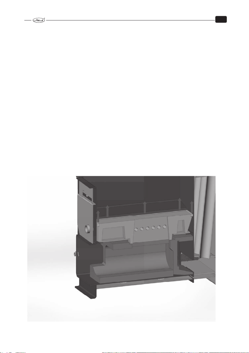
EN
Maintenance once a year or in a case of need (by a qualified person)
Start the burn–down by the menu buttons and wait, until the fuel in the burner burns–out. Turn
the burner off by the burner switch and by the main switch, plug out the mains cord of the boiler
from the mains socket. Open the door with burner to cca 90°.
1. Put down the burner cover and wipe the photocell by a rag and a soft abrasive agent (tooth
paste). Be carefull by the flat cable of display and buttons!
2. Clean the air wings of the fan. The most suitable way is to blow them with compressed air.
3. Screw out the scrape and ignition board.
4. Clean the space behind the ignition board.
5. Scrape ignition board and scraper.
6. Brush the grate utterly and clean the holes in the grate.
7. Mount all the parts back.
8. Clean the container and the pellet feeder from dust and small dirts.
9. Check state of the inlet hose for pellets.
10. Put the pellet feeder into operation by plugging of the feeder´s mains cord into the mains
socket (230 V~) to fill it with pellets.
11. Set the amount of pellets to be supplied.
10.2 INSTALLATION AND REPLACEMENT OF THE FIREPROOF PARTS
If you want to make exchange or control of fireproof parts, follow these steps:
1. Start–up the fan
2. Clean the boiler from combustion residues, ash, dust and tars
3. Remove glass sealing cords as shown at the picture
58
Page 60

EN
4. Take out the jet
5. After removing the jet it is possible to take out the ashtray (see picture)
6. Remove the rear ceramic part (see picture)
Installation of fireproof parts make opposite way as described above.
59
Page 61

EN
11 TRANSPORT, HANDLING AND STORING
In production is the boiler laid on a pallet and fixed by technological screws. It is packed in
a paper box, tied up by a tape and wrapped in stretch foil.
Transport, handling and storing of the packed product is allowed only on this pallet.
There are the hanging eyes placed under the upper cover to enable handling with a crane.
Only an approved person can ensure handling with this product.
11.1 INSTRUCTIONS FOR PRODUCT DISPOSAL AFTER TERMINATION
OF ITS SERVICE LIFE
Ensure the disposal of the appliance (boiler) by the waste disposal service, eventually use the
regulated waste dump, controlled by the municipal authority.
11.2 DISPOSAL OF THE PACKAGING
Dispose the packaging by the waste disposal service, eventually use the regulated waste dump.
11.3 ACCESSORIES
The ATTACK DPX boiler is delivered functionally tested, packed and laid on a wood pallet. It is
delivered with the instruction manual.
The following accessories are included in the delivery:
• Instruction manual
• Warranty certificate
• List of contractual service organizations
60
Page 62

EN
k
12 POSSIBLE ERRORS AND SOLUTIONS
Error Cause Solution
The indicator light „mains“ does
not shine
The boiler does not achieve the
required parameters
Door are not tight
Fan does not rotate or it is noisy
No voltage in the mains
Plug is not properly connected to the
socket
Faulty mains switch
Damaged current inlet conductor
Lack of water in the system
Too high pump output
Boiler output is not adequate to the
heating system
Fuel of low quality
Heat up flap is not tight
Low chimney draught
High chimney draught
Long heating up or operation with the
heat up flap open
Deformation of the fan blades
Insufficiently cleaned boiler
Clogged air inlet into the combustion
chamber
Damaged glass fibre cord
Nozzle is being clogged
Low chimney draught
If the non–returnable thermostat is
used, it is disconnected by overheating
Clogged radial impeller
Faulty capacitor
Faulty motor
Faulty contact in the socket of the current inlet conductor from the motor
Chec
Check
Replace
Replace
Refill
Set the flow and switching
Matter of the project
Burn dry and chopped wood
Fix
New chimney, suitable connection
Install the restriction flap into the
flue connection
Close the heat up flap
Replace
Clean
Clean
Replace, adjust the door hinges
Do not burn small wood pieces and
rind
Wrong chimney
Press the button of the thermostat
Clean the fan
Replace
Replace
Check
61
Page 63

EN
Burner turned off.
Check, which alarm is displayed.
If the display is black and without text, check the thermal fuse of the boiler. If there is no error,
probably is just the burner´s thermal fuse turned off. To start again, turn the power supply into
the burner off, remove the cover and press the small button between the connections of the
fuse of overheating. The thermal fuse is placed directly in the fuel–inlet tube. After restart,
mount the cover back and turn on the energy supply. Thermal fuse of the burner is switched off
at the temperature of 93 °C.
Signal text on display Explanation
ERROR: IGNITION FAILED 10
ERROR: FIRE LOST DURING COMBUSTION Extinction by heating, restart
failed
ERROR: FIRE SENSOR Faulty photocell, abnormal light 12
ERROR: CIRCUIT BOARD OVERHEATED Temperature under the cover is
too high
ERROR: TEMPERATURE SENSOR „TOO LOW“ Faulty thermal sensor of the
built–in operation thermostat
ERROR: TEMPERATURE SENSOR „TOO
HIGH“
Faulty thermal sensor of the
built–in operation thermostat
ERROR: OPTO–SWITCH Faulty circuit board 16
ERROR: FAN ALWAYS ON Ventilator rotates, when it is not
supposed to
ERROR: FAN STOP Ventilator is stopped, when it is
not supposed to be
ERROR: FAN SLOW Ventilator rotates too slowly 20
ERROR: IGNITION 1 First ignition trial failed 21
ERROR: STOCKER Pellet feeder is not connected to
the burner
ERROR: BURN–DOWN FAILED Photocell recognizes signal also
15 minutes after setting „Burn–
down“
ERROR: LIGHT LOST DURING BURNING Photocell does not recognize
fire, restart failed
ERROR: SCRAPER NOT OPERATING Fault in circuit board of scraper
or in grate gear
ERROR: SCRAPER JAMMED Grate moves too slowly 26
Error code
at recording
11
13
14
15
18
19
22
23
24
25
62
Page 64

EN
Possible causes of burner faults
Error
Possible cause Actions to correction
code
10 Feeder does not supply enough of pellets.
Empty pellet container.
Faulty ignition fuse.
Faulty ignition spiral.
Photocell needs to be cleaned.
11 Feeder does not supply enough of pellets.
Empty pellet container.
Faulty ignition fuse.
Faulty ignition spiral.
Photocell needs to be cleaned.
12 Short circuit or other fault of the photocell. Replace the photocell.
13 Too high temperature in the boiler room. Prevent from the heat leakage.
14 Faulty sensor of thermostat Replace the sensor.
15 Faulty sensor of thermostat Replace the sensor.
16 Faulty circuit board Replace the circuit board.
18 Ventilator runs, while the burner is in pause mode. Replace the circuit board.
19 Ventilator does not run, when it should. Change the ventilator fuse
20 Ventilator runs too slowly Clean the ventilator; replace the
21 First ignition trial failed Set the pellet ration.
22 Pellet feeder missing Connect the pellet feeder
23 Incorrect pellet supply Set pellet ration.
24 Incorrect amount of pellets supplied.
Faulty photocell
25 Cleaning does not work Check the connection between
26 Cleaning is slow Clean the grate
Set the pellet ration.
Fill the container.
Replace the fuse. (6.3 A).
Replace the spiral. (48 Ώ +/− 5 %).
Clean the photocell.
Set the pelletration.
Fill the container.
Replace the fuse. (6.3 A).
Replace the spiral. (48 Ώ +/− 5 %).
Clean the photocell.
(800 mA); check the connections;
replace the ventilator
ventilator
Set the pellet ration.
Replace the photocell.
the circuit board of scraper and
the main circuit board.
63
Page 65

12.1 CHARAKTERISTICS OF TEMPERATURE SENSORS
Characteristics under different temperature sensors are provided below:
1. The boiler temperature sensor readout by PROFI PID controller
2. The flue gas temperature sensor readout by PROFI PID controller
3. The boiler temperature sensor readout by Automatic 8 – 30 or 15 – 50 kW burner
According to the resistance of the sensor and temperature can be easily measured by the electrometer if the sensor is defective and has the right characteristics. Unless sensor indicates values significantly different from the above–mentioned characteristics, or if does not show anything at all, is probably damaged. In this case, the sensor needs to be replaced.
ATTENTION: Temperature and flue gas sensors have the same characteristics, but different temperature resistance. Therefore, the boiler sensor and flue gas temperature
sensor never mix with each other!
Resistance to [Ω]
Temperature [°C]
−20 1 367 921 98 089
−10 1 495 960 55 733
0 1 630 1 000 32 813
10 1 772 1 039 19 956
20 1 922 1 077 12 503
30 2 080 1 116 8 050
40 2 245 1 155 5 315
50 2 417 1 193 3 591
60 2 597 1 232 2 478
70 2 785 1 270 1 744
80 2 980 1 308 1 250
90 3 182 1 347 911
100 3 392 1 385 675
110 3 607 1 422 507
120 3 817 1 460 386
130 4 008 1 498 298
140 4 166 1 535 233
150 4 280 1 573 184
160 1 610
170 1 647
180 1 684
190 1 721
200 1 758
210 1 795
220 1 831
230 1 868
240 1 904
250 1 940
1 2 3
KTY81–210 Pt 1000 Burner
EN
64
Page 66
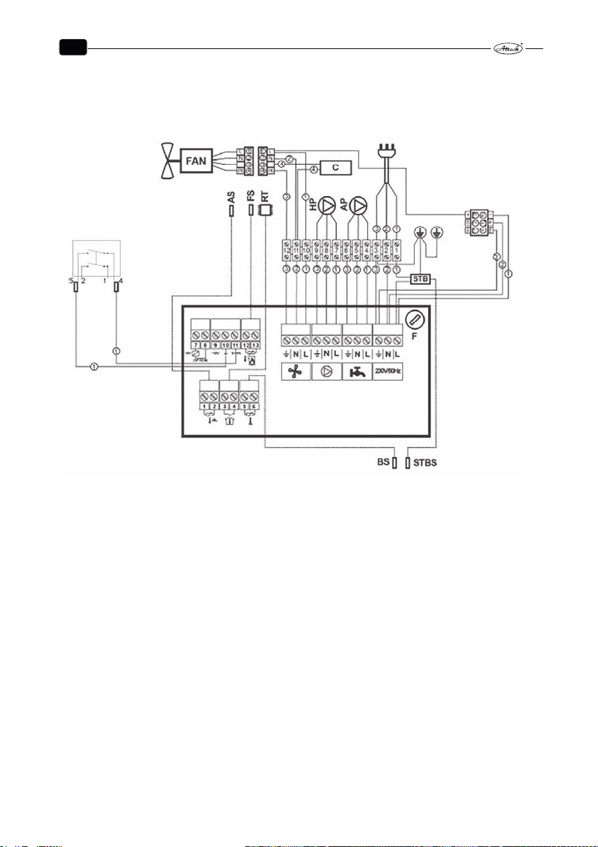
EN
13 ELECTRICAL SCHEMES
13.1 ATTACK DPX 25, 30, 35 COMBI PELLET
65
Page 67
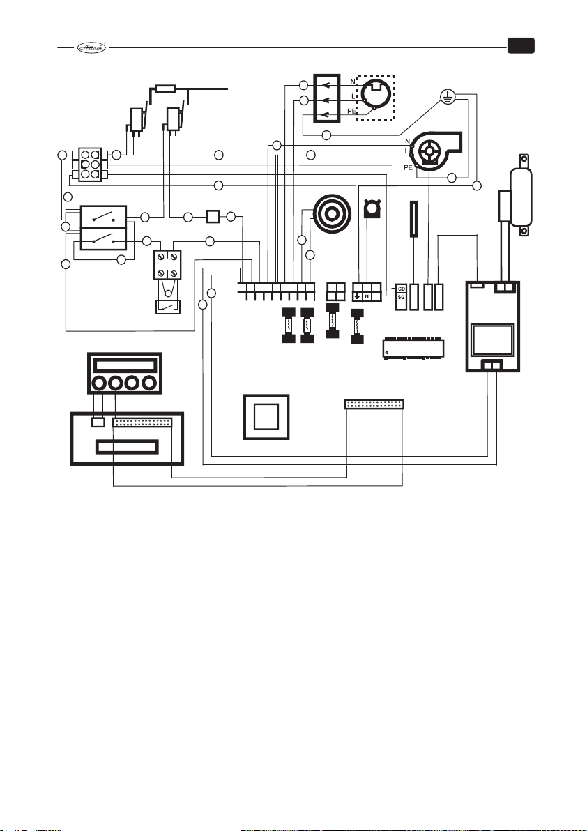
EN
MP
ZA
2
1
2
567
L
F1
1
1
1
2
1
1
89
LL
F2
3
OS
1213PE 15
**
F3
F5
PC
VH
3
SK
16
L
3
M
-
+
CE
TS2
FAN
LEV
ASH
RC
NL
KSH
KSV
1
L
3
6
LV
1
2
2
2
1
5
2
N
GD
4
1
PE
SG
HV
6
5
4
3
1
1
2
1
V
1
1
1
12
1
1
1
3
TF
1
1
1
1
1
2
1
2
1
1
34
L
L
NNNN
L
TP
EH
ED
L – phase conductor
N – neutral wire
PE - earthing conductor
LV – fan’s phase conductor
1 – black conductor
2 – blue conductor
3 – green-yellow conductor
4 – red conductor
KSV – end fan switch
KSH – main end switch
TF – thermal fuse
F - fuse
TP – the place for connecting of room thermostat
HV – main switch
V – switch of burner’s operation
EH – electronics of burner
RC – control chip
PC - photocell
SK – sensor of boiler’s temperature
OS – heating spiral
VH – fan of burner
C – capacitor
MP – engine of feeder
ZA - plug
ED – electronics of display
KSZ – back end switch (farther of combustion chamber)
KSP – front end switch (closer to combustion chamber)
M – engine of cleaning of burner’s grate
LEV – connector for the communication PROFI PID
TS2 - the place for connecting of sensor of boiler’s temperature
FAN - the place for connection of sensoring of fan’s turns
ASH – connection of cleaning electronics for 30kW burner
HP – heating circuit pump
AP – additional pump
AS – additional sensor
FS – flue gas temperature sensor
RT – room thermostat for PROFI PID
STB – emergency thermostat
BS – boiler’s temperature sensor PROFI PID
STBs – capillary emergency thermostat
C1, C2 ... C27 - labelling of cables
VEN – exhaust fan
CE – cleaning electronics
66
Page 68
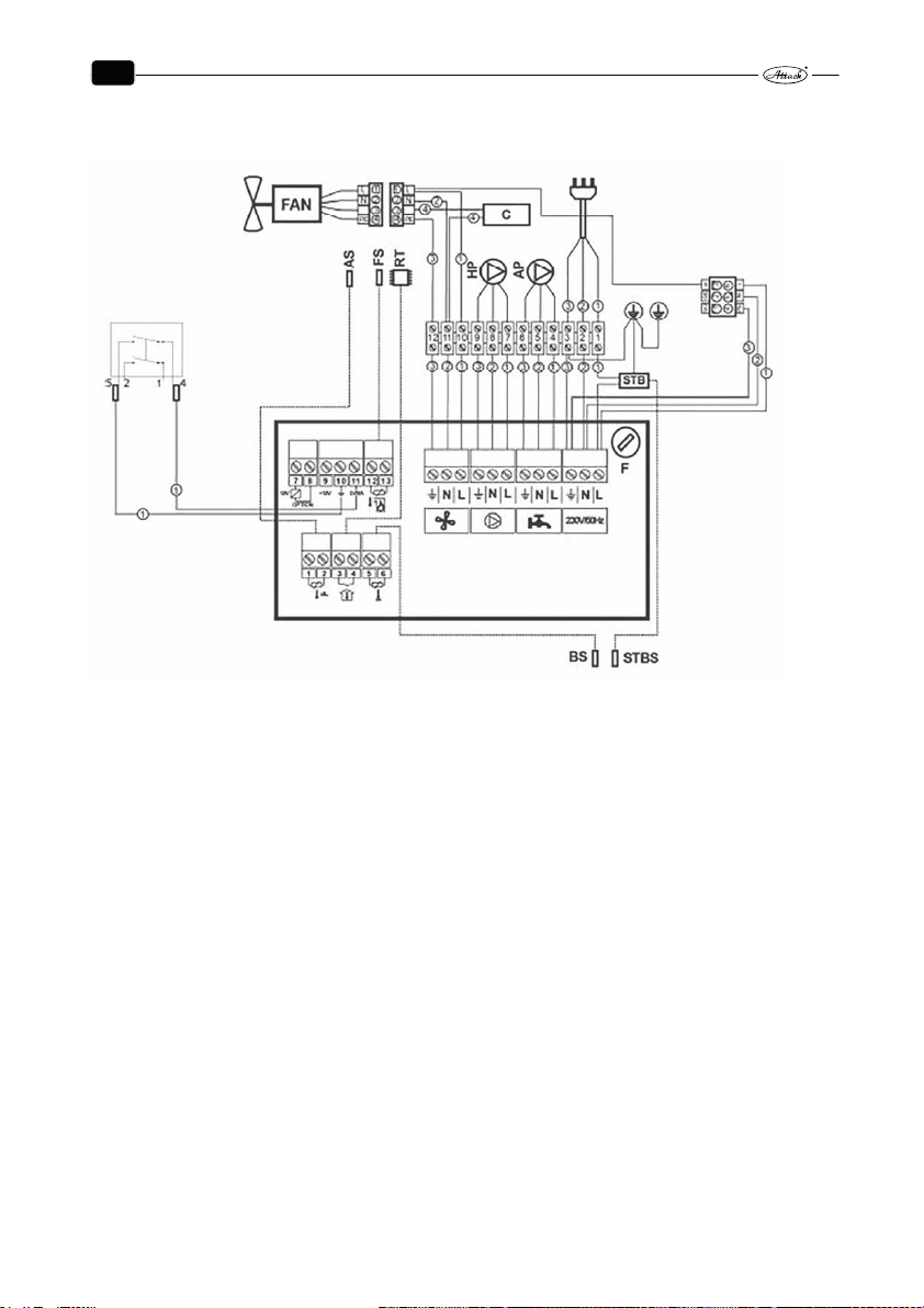
EN
13.2 ATTACK DPX 40, 45, 50 COMBI PELLET
67
Page 69
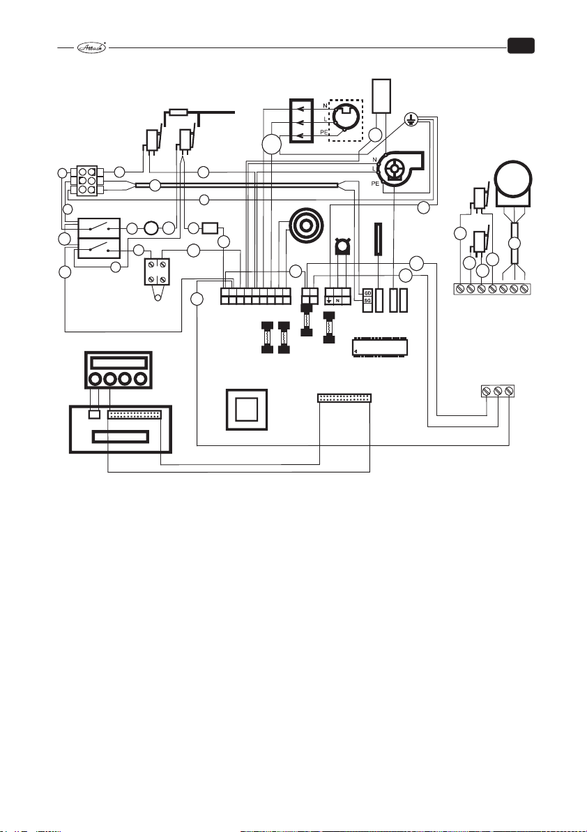
EN
C27
MP
C
C20
VH
KSV
ZA
KSH
C10
1
L
C1
N
PE
C6
C14
C15
ED
1
3
6
C5
LV
5
2
GD
4
1
SG
HV
6
4
3
1
V
C8
5
1
C2
F
2
1
C9
1
C4
1
TP
1
C17
C7
TF
C11
C3
C12
1
C18
3
2
1
C16
L
L
NNNN
L
X - SVORKOVNICA
L – phase conductor
N – neutral wire
PE - earthing conductor
LV – fan’s phase conductor
1 – black conductor
2 – blue conductor
3 – green-yellow conductor
4 – red conductor
KSV – end fan switch
KSH – main end switch
TF – thermal fuse
F - fuse
TP – the place for connecting of room thermostat
HV – main switch
V – switch of burner’s operation
EH – electronics of burner
RC – control chip
PC - photocell
SK – sensor of boiler’s temperature
OS – heating spiral
VH – fan of burner
4567
L
F1
KSZ
C21
KSP
C24
1
C19
TS2
FAN
ASH
RC
C25
7
P - SVORKOVNICA
89
LL
F2
SK
PC
OS
C13
16
PE 15
13
12
L
**
LEV
F3
F5
EH
C – capacitor
MP – engine of feeder
ZA - plug
ED – electronics of display
KSZ – back end switch (farther of combustion chamber)
KSP – front end switch (closer to combustion chamber)
M – engine of cleaning of burner’s grate
LEV – connector for the communication PROFI PID
TS2 - the place for connecting of sensor of boiler’s temperature
FAN - the place for connection of sensoring of fan’s turns
ASH – connection of cleaning electronics for 30kW burner
HP – heating circuit pump
AP – additional pump
AS – additional sensor
FS – flue gas temperature sensor
RT – room thermostat for PROFI PID
STB – emergency thermostat
BS – boiler’s temperature sensor PROFI PID
STBs – capillary emergency thermostat
C1, C2 ... C27 - labelling of cables
VEN – exhaust fan
CE – cleaning electronics
C23
1
C26
CE
L1L2N
M
U2 Z2 U1
C22
3456
12
68
Page 70
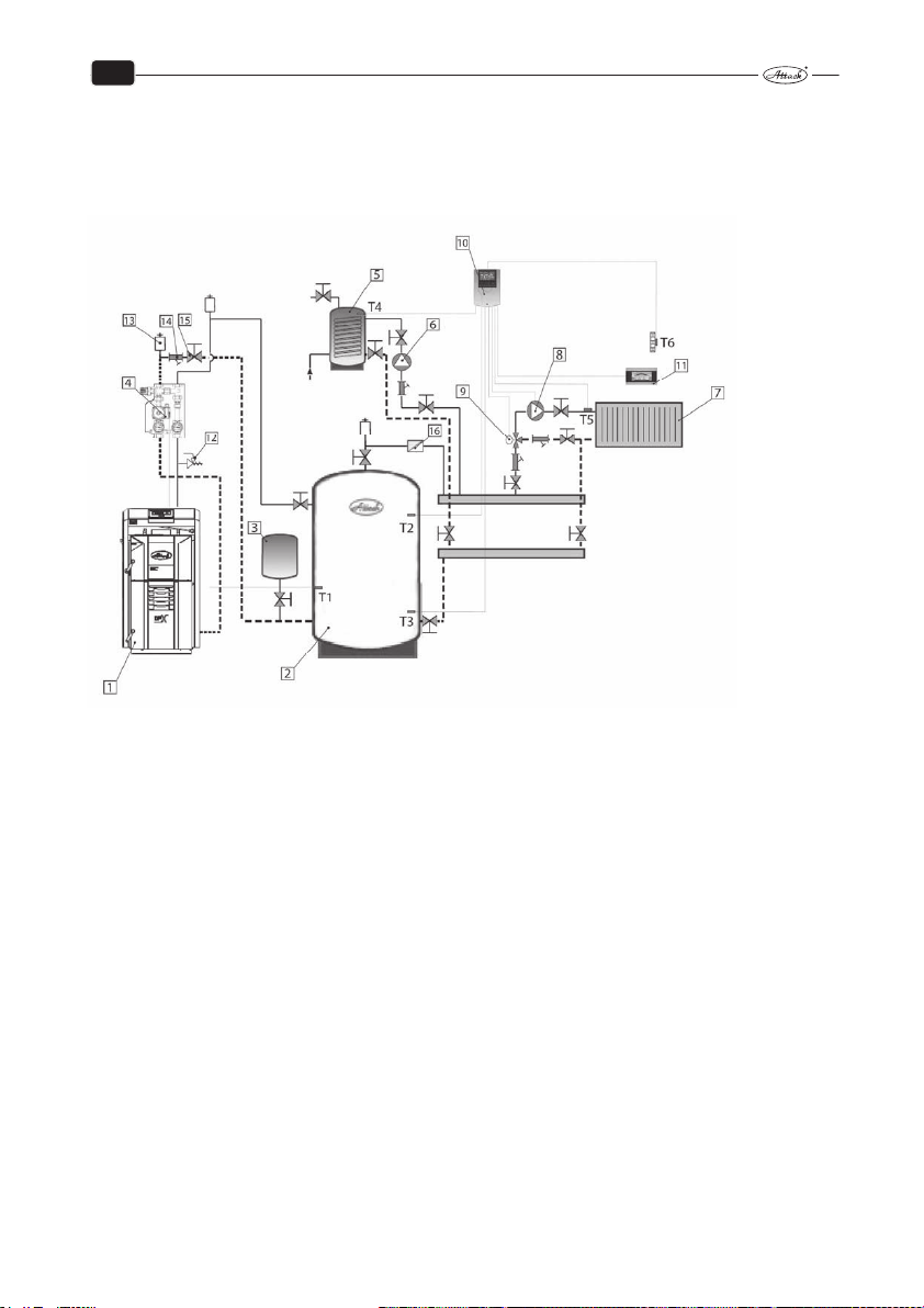
EN
14 RECOMMENDED SCHEMES OF CONNECTION
14.1 CONNECTION OF THE BOILER WITH 1 HEATING CIRCUIT WITH
DHW
1 Wood gasifying boiler ATTACK DPX COMBI PELLET with regulation PROFI PID
2 Accumulation tank ATTACK
3 Expanse vessel
4 Mixing device ATTACK OVENTROP with pump class A
5 Tank for DHW
6 Pump of tank for DHW (WILO YONOS PARA RS25/6 130 mm, WILO YONOS PARA RS 25/6 RKC 180mm)
7 Set of radiators ATTACK K, VK
8 Pump of heating circuit of radiators (WILO YONOS PARA RS25/6 130 mm;
WILO YONOS PARA RS25/6 RKC 180 mm)
9 Three-way mixing valve of radiators (DN20, KVS 2,5; DN20, KVS 4,0; DN20, KVS 6,3; DN20, KVS 10;
DN32, KVS 16; DN40, KVS 25; DN50, KVS 40)
10 Regulator 1 mixing circuit TECH CS-431N
11 Room regulator (TECH CS-292 V3, CS-296 with RS communication, CS-282 with RS communication)
12 Safety valve
13 Deaeration valve
14 Filter
15 Ball tap
16 Return(backflow) valve
T1 Boiler temperature sensor in accumulation tank
T2,3 Additional temperature sensor in accumulation tank
T4 Additional temperature sensor in DHW tank
T5 Additional temperature sensor in radiators
T6 Additional sensor of external temperature
69
Page 71
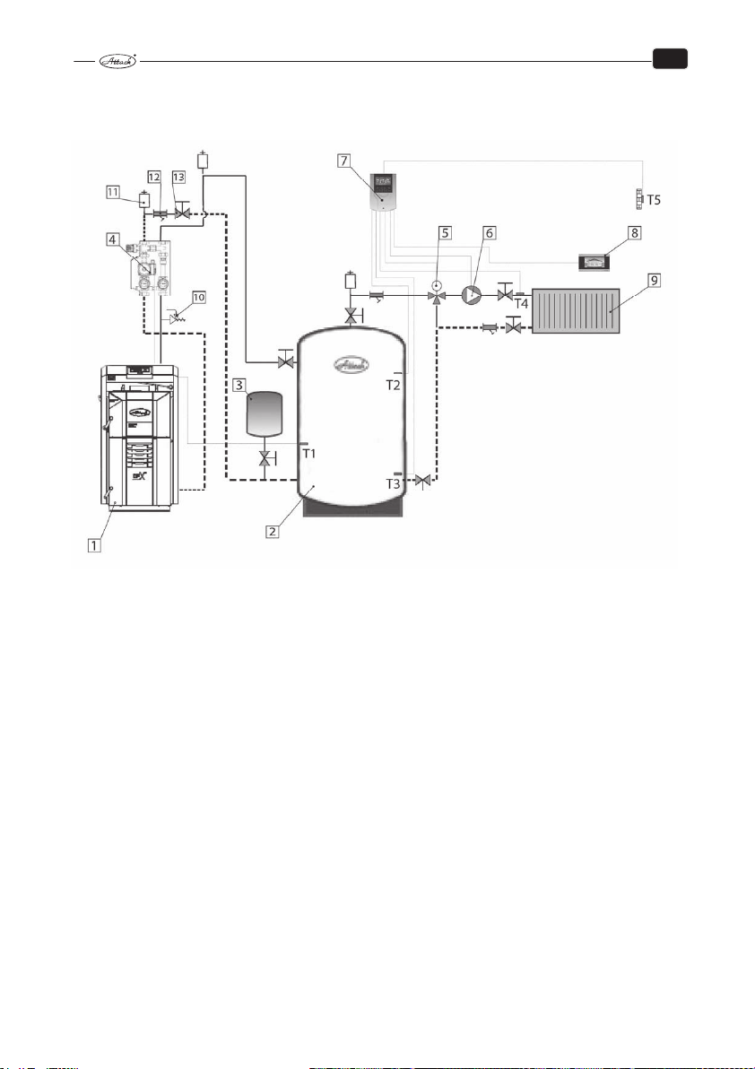
14.2 CONNECTION OF THE BOILER WITH 1 HEATING CIRCUIT
WITHOUT DHW
EN
1 Wood gasifying boiler ATTACK DPX COMBI PELLET with regulation PROFI PID
2 Accumulation tank ATTACK
3 Expanse vessel
4 Mixing device ATTACK OVENTROP with pump class A
5 Three-way mixing valve of radiators (DN20, KVS 2,5; DN20, KVS 4,0; DN20, KVS 6,3; DN20,
KVS 10; DN32, KVS 16; DN40, KVS 25; DN50, KVS 40)
6 Pump of heating circuit of radiators (WILO YONOS PARA RS25/6 130 mm;
WILO YONOS PARA RS25/6 RKC 180 mm)
7 Regulator 1 mixing circuit TECH CS-431N
8 Room regulator (TECH CS-292 V3, CS-296 with RS communication, CS-282 with
RS communication)
9 Set of radiators ATTACK K, VK
10 Safety valve
11 Deaeration valve
12 Filter
13 Ball tap
T1 Boiler temperature sensor in accumulation tank
T2,3 Additional temperature sensor in accumulation tank
T4 Additional temperature sensor in radiators
T5 Additional sensor of external temperature
70
Page 72
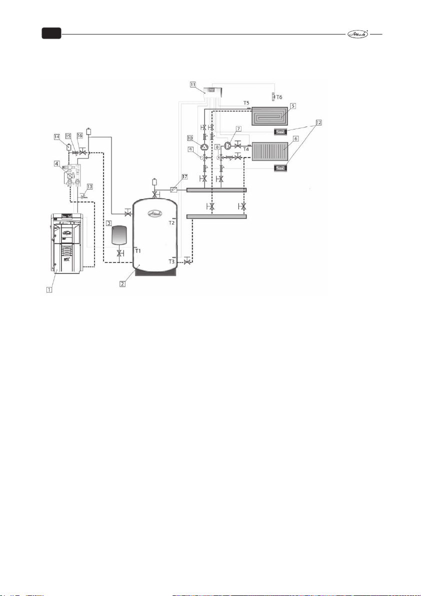
EN
14.3 CONNECTION OF THE BOILER WITH 2 HEATING CIRCUITS
WITHOUT DHW
1 Wood gasifying boiler ATTACK DPX COMBI PELLET with regulation PROFI PID
2 Accumulation tank ATTACK
3 Expanse vessel
4 Mixing device ATTACK OVENTROP with pump class A
5 Floor heating system
6 Set of radiators ATTACK K, VK
7 Pump of heating circuit of radiators (WILO YONOS PARA RS25/6 130 mm; WILO YONOS PARA
RS25/6 RKC 180 mm)
8 Three-way mixing valve of radiators (DN20, KVS 2,5; DN20, KVS 4,0; DN20, KVS 6,3; DN20, KVS 10;
DN32, KVS 16; DN40, KVS 25; DN50, KVS 40)
9 Three-way mixing valve of the floor heating (DN20, KVS 2,5; DN20, KVS 4,0; DN20, KVS 6,8; DN25,
KVS 10; DN32, KVS 16; DN40, KVS 25; DN50, KVS 40 )
10 Pump of floor heating circuit (WILO YONOS PARA RS25/6 RKC 130 mm,
WILO YONOS PARA RS25/6 RKC 180 mm)
11 Regulator of 2 heating circuits TECH CS-408N
12 Room regulator with RS communication TECH CS-282, CS-292 V3, CS-296 (always only 1 with
RS communication)
13 Safety valve
14 Deaeration valve
15 Filter
16 Ball tap
17 Return(backflow) valve
T1 Boiler temperature sensor in accumulation tank
T2,3 Additional temperature sensor in accumulation tank
T4 Additional temperature sensor in radiators
T5 Additional temperature sensor in floor
T6 Additional sensor of external temperature
71
Page 73
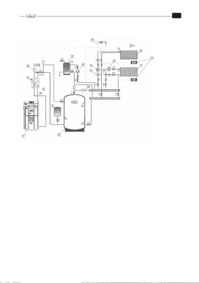
EN
14.4 CONNECTION OF THE BOILER WITH 2 HEATING CIRCUITS WITH
DHW
1 Wood gasifying boiler ATTACK DPX COMBI PELLET with regulation PROFI PID
2 Accumulation tank ATTACK
3 Expanse vessel
4 Mixing device ATTACK OVENTROP with pump class A
5 Tank for DHW
6 Pump of tank for DHW (WILO YONOS PARA RS25/6 130 mm, WILO YONOS PARA RS 25/6 RKC 180mm)
7 Set of radiators ATTACK K, VK
8 Pump of heating circuit of radiators (WILO YONOS PARA RS25/6 130 mm;
WILO YONOS PARA RS25/6 RKC 180 mm)
9 Floor heating system
10 Three-way mixing valve of radiators (DN20, KVS 2,5; DN20, KVS 4,0; DN20, KVS 6,3; DN20, KVS 10; DN32,
KVS 16; DN40, KVS 25; DN50, KVS 40)
11 Mixing valve of floor
12 Pump of floor heating circuit (WILO YONOS PARA RS25/6 RKC 130 mm,
WILO YONOS PARA RS25/6 RKC 180 mm)
13 Regulator of 2 heating circuits TECH CS-408N
14 Room regulator with RS communication TECH CS-282, CS-292 V3, CS-296 (always only 1 with
RS communication)
15 Safety valve
16 Deaeration valve
17 Filter
18 Ball tap
19 Return(backflow) valve
T1 Boiler temperature sensor in accumulation tank
T2,3 Additional temperature sensor in accumulation tank
T4 Additional temperature sensor in DHW tank
T5 Additional temperature sensor in radiators
T6 Additional temperature sensor in floor
T7 Additional sensor of external temperature
72
Page 74

CONTENTS
1. INSTALLATION AND CHIMNEY PARAMETERS................................................................................................. 4
2. VERIFICATION OF THE CORRECT CHIMNEY PARAMETERS ......................................................................... 5
3. DEVICES FOR CHIMNEY DRAUGHT MEASURING ........................................................................................... 6
4. OPERATION PRESSURE IN HYDRAULIC CIRCUIT ............................................................................................ 7
5. BOILER PROTECTION AGAINST EXCESSIVE CONDENSATION – ATTACK-OVENTROP ........................ 7
6. CORRECT ASHTRAYS POSITION ........................................................................................................................... 8
7. FUEL .............................................................................................................................................................................. 8
8. AFTERCOOLING CIRCUIT INSTALLATION ......................................................................................................... 9
9. CORRECT ADJUSTMENT OF AIR INLETS ............................................................................................................ 9
10. ASHTRAY CLEANING .......................................................................................................................................... 10
11. HOW TO CLEAN SPACE AROUND THE ASHTRAY ..................................................................................... 12
12. EXCHANGER PIPES CLEANING BY LEVER OF TURBULATORS ............................................................... 13
13. HOW TO CLEAN SPACE UNDER EXCHANGER ........................................................................................... 14
14. POSITION OF LEVER OF TURBULATORS BY CLEANING .......................................................................... 15
15. TOOLS FOR CLEANING OF SPACE UNDER EXCHANGER ........................................................................ 16
16. CONTROL OF TUBULAR EXCHANGER´S FUNCTIONALITY ..................................................................... 17
17. ACCESS TO TUBULAR EXCHANGER .............................................................................................................. 17
18. EXCHANGER´S COVER REMOVAL .................................................................................................................. 18
19. CONTROL OF CORRECT FUNCTION OF THE HEAT-UP FLAP ................................................................. 18
20. TURBULATOR THREADS CLEANING.............................................................................................................. 19
21. CLEANING OF THE VENTILATOR´S OPERATION AREA ............................................................................ 20
22. CLEANING OF RADIAL IMPELLER’S VANES ................................................................................................. 21
23 SUMMARY OVERVIEW OF REGULAR CLEANING OF PARTICULAR BOILER PARTS .......................... 22
3
Page 75

WOOD GASIFYING BOILER
ATTACK® SLX, DPX
USER MANUAL
for correct installation,
operation and cleaning
W W W . A T T A C K . S K
Important! Read this manual properly before the boiler start-up!
Page 76

1. INSTALLATION AND CHIMNEY PARAMETERS
By installation of chimney connection to boiler it is necessary to care about correct outlet of flue
gas and eventual condensate, not to let it fall back into the boiler. For this purpose you can use
the T-piece, see picture below. Exhaust connection comes into the chimney vent. If it is not
possible to connect boiler to chimney vent directly, then the adequate extension of exhaust
connection has to be as short as possible, and no longer than 1 m, without additional heating
surface and it has to go up in direction to the chimney. Exhaust connections must not go
through foreign dwelling or utility units. Internal cross-section of the exhaust connection must
not taper in direction to the chimney. Try to minimize usage of elbows by installation. Chimney
has to be constructed in conformity with the norms STN 73 4201 and STN 73 4210.
Prescribed values of the correct height and
cross-section chimney dimensions:
DPX15, DPX25, DPX35, DPX45
20×20 cm min height 7 m
20 cm min. height 8 m
15×15 cm min height 11 m
16 cm min height 12 m
4
Page 77

2. VERIFICATION OF THE CORRECT CHIMNEY PARAMETERS
Correct boiler function significantly depends on quality chimney with correct parameters.
Minimum chimney diameter is 150 mm, however, 200 mm is recommended. Chimney has to be
designed or regulated to achieve prescribed draught of 23–30 Pa at nominal boiler flue gas
temperature value.
ATTENTION! Chimney which does not fulfil required parameters may cause limited
boiler function (Low flue gas temperature, low output, excessive condensation of
tubular exchanger, shorter life-time, even total boiler disfunction)! Guarantee does
not relate to the boiler installed with the chimney of incorrect parameters.
5
Page 78

3. DEVICES FOR CHIMNEY DRAUGHT MEASURING
It is possible to check correct chimney draught by some types of analysers or by exact
differential pressure-gauge. On the picture there is draught reducer too, also useful for correct
draught setting.
6
Page 79

4. OPERATION PRESSURE IN HYDRAULIC CIRCUIT
Operation pressure must not exceed limit of 2,5 bar.
ATTENTION! Expanse vessel and safety valve must be installed in the system.
5. BOILER PROTECTION AGAINST EXCESSIVE
CONDENSATION – ATTACK-OVENTROP
For correct boiler function and its long life-time it is necessary to keep return water temperature
always higher than 65 °C. Set boiler thermostat to 80-85 °C, which is ideal boiler operation
temperature. Boiler guarantee is valid only in case that the ATTACK-OVENTROP device was
installed into the hydraulic system.
ATTENTION! If the ATTACK OVENTROP device is not installed, it may cause shorter
boiler life-time.
7
Page 80
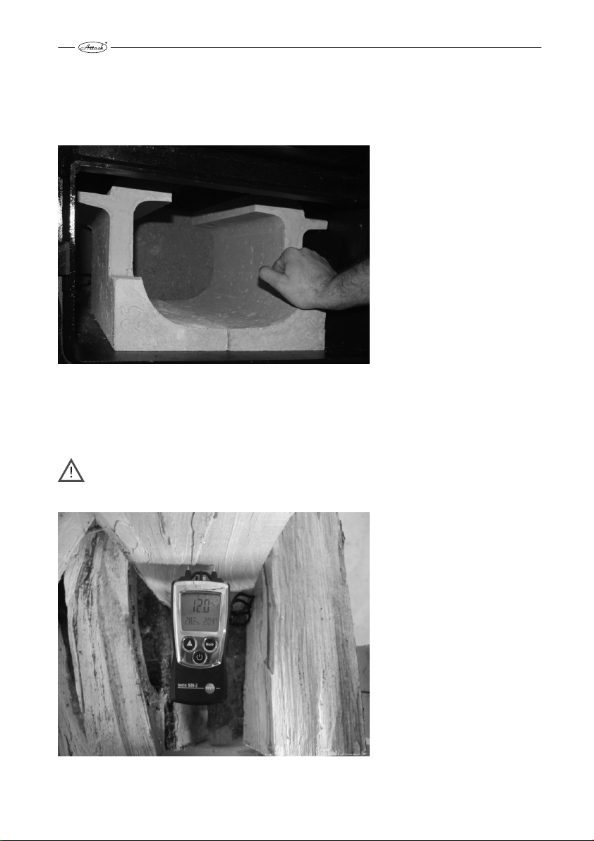
6. CORRECT ASHTRAYS POSITION
Ashtray position is important for correct boiler operation. It is not necessary to take out the
ashtray while cleaning, but it is important to check its correct position sometimes. Ashtray has to
be completely shifted rearwards.
7. FUEL
Use suitable fuel for wood gasifying boiler operation – soft or hard wood logs. Wood moisture
has to be in range of 12–20 % (related to time of min. 15 month of free storing at the fresh air).
Alternatively it is possible to use wood briquets of cylindrical shape with opening in the middle.
ATTENTION! Wood with moisture exceeding 20 % shortens boiler life-time, causes
lower output, excessive condensation in tubular boiler exchanger, which may
require additional out-of-warranty service!
8
Page 81
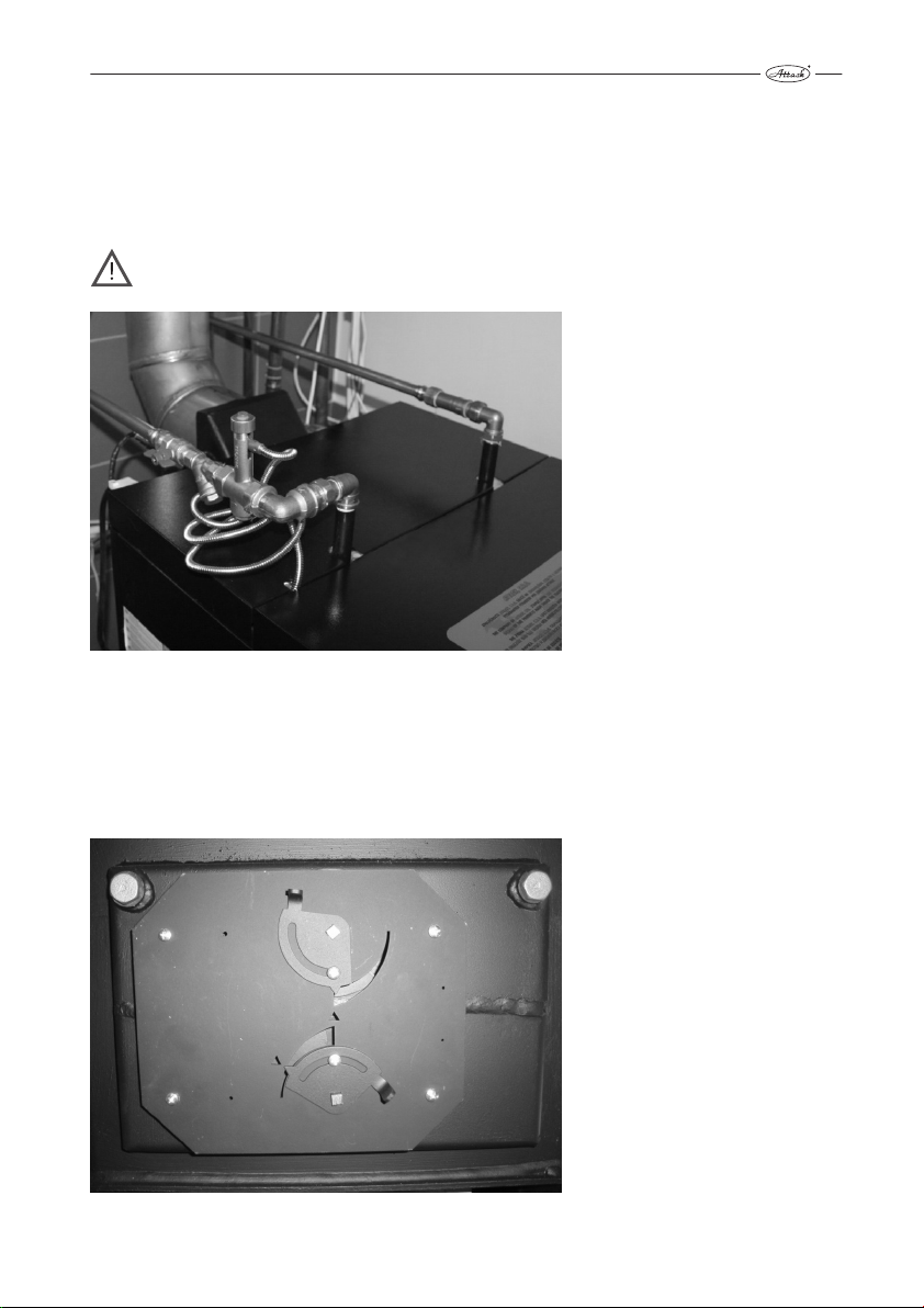
8. AFTERCOOLING CIRCUIT INSTALLATION
Boiler warranty is valid only in case, that functional thermostatic valve, connected to the cold
water source, is installed in the boiler aftercooling circuit. If the cold water source depends on
electricity (home water plant), whole device can be out of order in case of power failure. In this
cases, use water tanks placed higher than boiler, connected to thermostatic valve. Tank volume
has to be appropriate to the boiler outuput.
ATTENTION! If there is no aftercooling circuit on the boiler and it comes to boiler
overheating, serious and non-recurring damage or even fire may occure.
9. CORRECT ADJUSTMENT OF AIR INLETS
Correct adjustment of primary and secondary air by STANDARD and PROFI boilers is marked on
tin-plate and it is not necessary to manipulate with that. Correct setting of primary air (upper
butterfly) is 100 %, secondary air (bottom butterfly) is set to 35 %. This relates to all outputs of
DPX boilers (15, 25, 35, 45).
9
Page 82
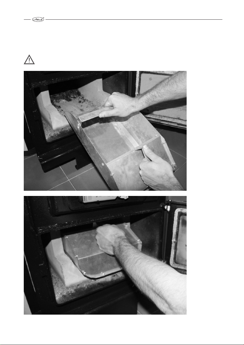
10. ASHTRAY CLEANING
Internal space of ashtray has to be cleaned from accumulated ash at least 1× a day. Cleaning
with scoop is very effective and easy. Cleaning can be done very easily and fast also by full boiler
operation.
ATTENTION! Hot ash from ashtray can still smoulder, therefore it is not supposed to
be put into trash bin, however into appropriate tin-plate bin, not to cause the fire.
10
Page 83
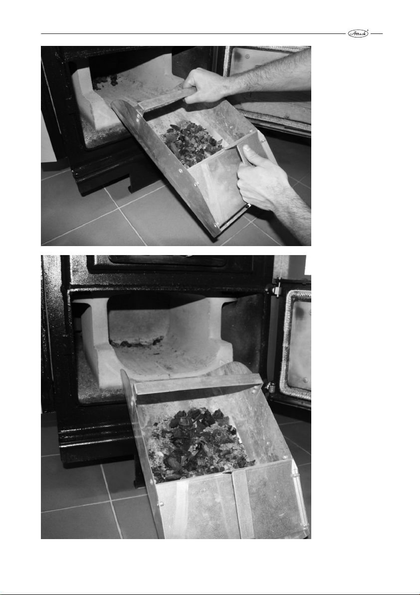
11
Page 84
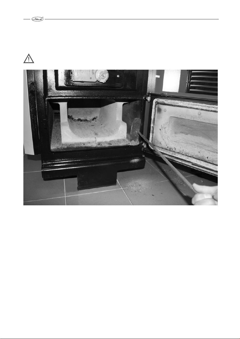
11. HOW TO CLEAN SPACE AROUND THE ASHTRAY
Space around the ashtray has to be cleaned regularly, at least 1× a week. Use suitable tool, fire
hook delivered with boiler is ideal for this purpose. It is not necessary to take out the refractory
pieces from the boiler´s ashtray.
ATTENTION! Unsufficiently cleaned space around ashtray may cause limited boiler
function.
12
Page 85
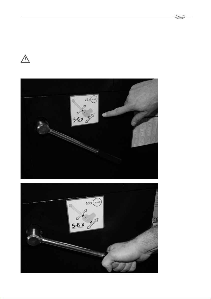
12. EXCHANGER PIPES CLEANING BY LEVER OF
TURBULATORS
It is necessary to move lever of turbulators cleaning regularly, preferably by every boiler loading,
at least 3 times a day. It is necessary to move it by full lever uplift, 5–6 times upwards and
downwards.
ATTENTION! If it is not moved with the lever regularly, exchanger pipes may clog
and therefore cause turbulators blockage, lower efficiency, decreased output and
incorrect boiler function. In this case is boiler warranty not valid. If you cannot
move the lever of turbulators, stop the boiler and call specialized service.
13
Page 86
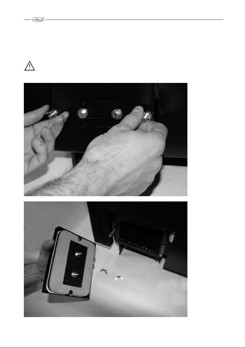
13. HOW TO CLEAN SPACE UNDER EXCHANGER
It is necessary to clean space under exchanger pipes in regular intervals. This interval depends
on boiler operation time, but it has to be done at least 1× a week. Remove cover of the opening
for cleaning carefully, not to damage the sealing. After cleaning of space under exchanger,
install the cover – it has to be sufficiently screwed and air-proof.
ATTENTION! Otherwise there may come to insufficient air circulation in the boiler
and thereby to incorrect boiler function (ineffective combustion, decreased output,
low flue gas temperature, etc.).
14
Page 87
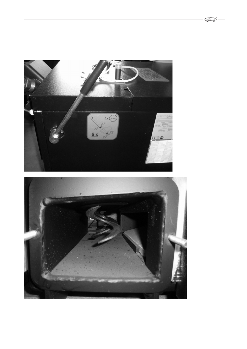
14. POSITION OF LEVER OF TURBULATORS BY CLEANING
To clean space under exchanger of the DPX 15, 25, 35 boilers, it is necessary to lift lever of
turbulators fully up, turbulators go into the pipes and thereby there is free space for cleaning. By
the DPX 45 boiler it is ideal to lift the lever into middle position.
15
Page 88
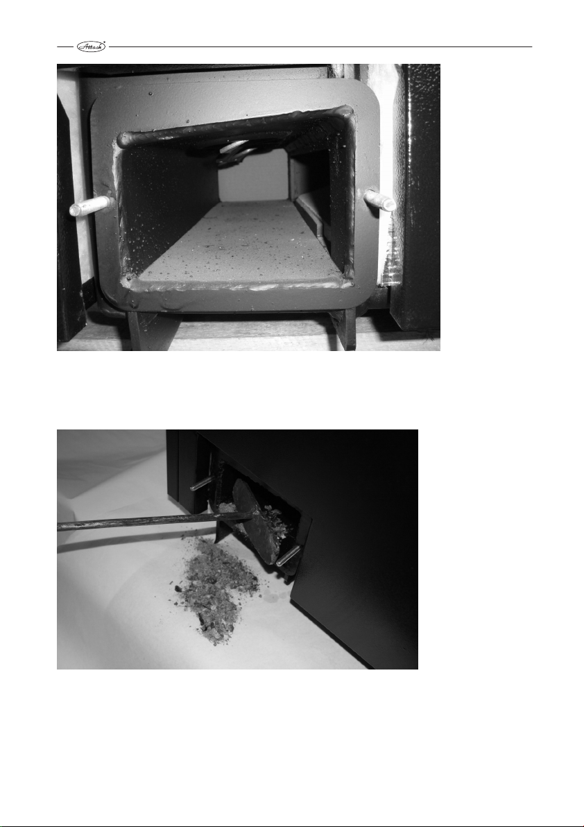
15. TOOLS FOR CLEANING OF SPACE UNDER EXCHANGER
To clean space under exchanger it is possible to use fire hook delivered with the boiler.
16
Page 89
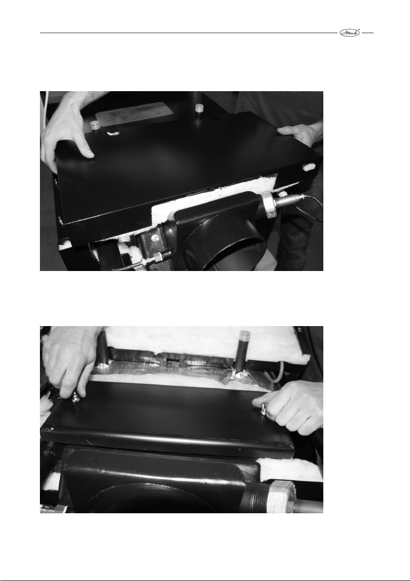
16. CONTROL OF TUBULAR EXCHANGER´S FUNCTIONALITY
Check regularly correct functionality of tubular exchanger – at least 1× a month. Firstly, remove
rear upper cover.
17. ACCESS TO TUBULAR EXCHANGER
Release wing matrices.
17
Page 90

18. EXCHANGER´S COVER REMOVAL
Check correct functionality fo turbulators, while the boiler is out of order. Remove the cover to
get to the tubular exchanger.
ATTENTION! Cover must be sufficiently tighten and air-proof. Otherwise it may
cause incorrect boiler function
19. CONTROL OF CORRECT FUNCTION OF THE HEAT-UP FLAP
For correct function of the heat-up flap it is necessary to check and clean bearing surfaces
regularly.
18
Page 91
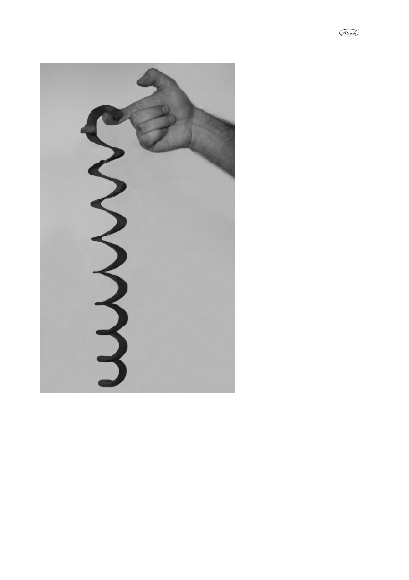
20. TURBULATOR THREADS CLEANING
If the boiler was from any reason
operated in incorrect way, it is
possible, that the turbulators were
clogged and thereby the flue gas
transition was decreased. In this case
it is necessary to demount
turbulators and to clean the space
between particular threads, for
example by wire brush. Put the
turbulators back into the pipes, not
to decrease efficiency of the boiler.
(This is not related to the 15 DPX
model).
19
Page 92

21. CLEANING OF THE VENTILATOR´S OPERATION AREA
Operation space of the ventilator´s radial impeller has to be cleaned at least 1× a year. To do so,
release matrices of the ventilator´s flange and demount ventilator. Clean the operation area
from soot and mud. By demounting, take care to tighten matriaces of the ventilator´s flange
sufficiently.
ATTENTION! Demount ventilator, while boiler is out of order. Insufficiently cleaned
ventilator´s operation area may cause its limited function.
20
Page 93

22. CLEANING OF RADIAL IMPELLER’S VANES
Vanes of ventilator have to be cleaned from dirt at least 1× a year by suitable tool (wire brush).
ATTENTION! Too dirty vanes of ventilator decrease its efficiency and thereby cause
limited boiler function.
21
Page 94

23 SUMMARY OVERVIEW OF REGULAR CLEANING OF
PARTICULAR BOILER PARTS
Cleaning* Point Daily Weekly Annually
Ash removing 10 1×
Space around ash tray 11 1×
Space under exchanger 15 1×
Lever of turbulators 12 5–6×
Flap 19 1×
Space of ventilator 21 1×
Radial impeller of ventilator 22 1×
* Minimal recommended cleaning intervals. According to intensity of heating they can be also
shorter.
22
Page 95

Information about processing of personal data
Dear Customer,
You provide us your personal information by completing and sending the Boiler start-up recordand our company becomes your personal data manager in relation to you.
We hereby would like to inform you why and how we process your personal information, how
we collect your personal information, for what purpose we handle it and the legal basis of such
processing, how we handle personal data and what your rights are in relation to processing your
personal data.
Please read the following information carefully before providing us your personal details.
In case of any questions related to the processing of your personal data, please do not hesitate
to contact us at tel. no. 00421 43 400 3131 or support@attack.sk.
Privacy Manager:
ATTACK, s. r. o., with its registered office at Dielenská Kružná 5020, 038 61 Vrútky, Slovak Re-
public
Tel .: +421 43 4003 101
Fax .: +421 43 3241 129
E-mail: export@attack.sk
Web: http://www.attack.sk
Processing of personal data
We will only process the personal information you provide to us in the Boiler start-up record, i.e.:
- Name
- Surname
- Address
- Phone
- Type and serial number of the product
Purpose and legal basis for the processing of your personal data
We will process your personal data for the following purposes and on the basis of the
following legal bases.
1) For the purposes of direct marketing, which is a legitimate interest of our company. The
legal basis here is Art. Article 6 1. Letter. (f) Regulation (EU) 2016/679 of the European Parliament and of the Council of 27 April 2016 on the protection of natural persons with regard to the processing of personal data and on the free movement of such data, and repealing Directive 95/46/EC (General Data Protection Regulation).
The proccesing based on our legitimate interest, i.e. direct marketing, is following:
Your personal data will be stored in our electronic database which is managed directly
and only by us. This electronic database is stored and secured on the property of our
company. Your personal data will be used by our legitimate interest only in order to be
able to send you an offer of our new products, especially in the event of the end of the
expected life of product which you enter your personal data in the Boiler start-up record
in if our company develops a newer and more technologically superior and better product that could replace the product in which you enter your personal data into the in the
Boiler start-up record.
Direct marketingis our legitimate interest and the one of two purposes of processing of
Page 96

The length of time the personal data will be stored
We will process your personal data for at least the duration of the contractual warranty (i.e. for 5
years) for the purposes of fulfilling the warranty agreement and at most for thetime of assumed
lifetime of the products for which the Boiler start-uprecord for the purposes of direct marketing.
Raising objections toprocessing of personal data
Whenever you have the right to object to our processing of your data for direct marketing purposes (see Purpose and legal basis for processing your personal data, item 1) above). If you have
an objection to our processing of your direct marketing data, by the date of your objection will
cease our processing your personal data for direct marketing purposes.
The objection to the processing of your personal data for direct marketing purposes can be sent
to us by post to:
ATTACK, s. r. o., Dielenská Kružná 5020, 038 61 Vrútky, Slovak Republic. In the objection, it is sufficient to provide the name, address and the text "I hereby raise an objection to the processing
of my personal data for the purposes of direct marketing" and your signature. We always inform
you about the accepting your requestwithout delay.
Please note that the right to object can not be invoked against our processing of your personal
data necessary for the purpose of fulfilling the extended warranty agreement.
Your other rights related to the processing of personal data
Please note that you also have the following rights in relation to our processing of your personal
information:
• to ask for information about what personal data is processed by us,
• to request access to these data and let them update or fix,
• to require the deletion of these personal data, or the limitation of their processing,
• to raise objection to the processing of your personal data,
• the right to the portability of your personal data,
• in case of doubt regarding compliance with the obligations related to the processing of
your personal data, contact the Administrator or the Office for Personal Data Protection.
You may enforce these rights to our company by the same procedure as the right to raise objections to the processing of personal data.
Page 97

your personal data, i. e. direct offer of our products sent to you.
2) The legal basis for fulfilling the extended warranty agreement on the product in which
you enter the Boiler Startup Record whereare your personal data is Art. Article 6 1. Letter.
(f) Regulation (EU) 2016/679 of the European Parliament and of the Council of 27 April
2016 on the protection of natural persons with regard to the processing of personal data
and on the free movement of such data, and repealing Directive 95/46/EC (General Data
Protection Regulation).
This processing that is required to meet the extended warranty agreement for a product
you are one of the parties will be following:
Our company provides you with an extended contractual warranty (beyond the statutory
warranty) in such situation that you comply with the warranty conditions (see the warranty conditions in the Instruction for use, in whichthere is the Boiler start-up record with
your personal data ). In order to provide you with this extended contractual warranty we
need to know who is the other party and whether you are performing your obligations
under this agreement especially the mandatory annual service inspections. Therefore we
need you to send us a record of this inspection after each annual inspection (max. 5 inspections) and we will declare in our database that you fulfill the terms of the contractual
guarantee.
Since each contract has at least two contracting parties we need your personal data to
identify you as a party and identify a specific product for the purposes of fulfilling the extended warranty agreement. We would not be able to fulfill our obligations under the extended warranty agreementproperly without these data.
Our legitimate interest and one of the two purposes of processing your personal data is
therefore the fulfillment of the contract, that is, the fulfillment of the contract for extension of the contractual guarantee.
Processing of personal data for both purposes is done manually and also in electronic information systems. However these systems are subject to rigorous and constant physical and technical
control. All persons who, on the basis of our instructions and our credentials, come in contact
with personal data in the framework of their work or contractual obligations are bound by confidentiality.
Category of recipients of personal data
We process your personal data primarily by ourselves. However it may happen that we
will have to use the services of another entity to process personal data for any of the
above mentioned purposes. In this case the relationship between us and the third party
will be the relationship between the administrator andthe processor and we will make an agreement with this processor about the processing the personal data in order to guarantee the
security and legality of processing your personal data.
Your personal data may therefore be sold to the recipient of the following categories:
a) A company that distributes our products in the territory of a member state of the Europe-
an Union in which you have purchased a product which you enter your personal data in
the Boiler start-up record in or in which such a product is put into service on your request
b) A company providing bulk mailing services
Page 98

Page 99

Page 100

ATTACK, s.r.o. • Dielenská Kružná 5020, 038 61 Vrútky • Slovakia
Tel: +421 43 4003 101 • E-mail: kotle@attack.sk
Export – tel: +421 43 4003 115 • E-mail: export@attack.sk
All provid ed informati on is temporar y, subject to cha nge without no tice and for info rmational purposes only. Variations in
produc t visual displa y are possible and may not match the o ffer and range of e quipment fo r different mar kets. ATTACK s.r.o.
reserves t he right to make change s to specifications an d content without prio r notice. Pictures and p roduct specifica tions are
only info rmative. Price an d offer change s are reserved .
ATTACK, s.r.o. – 07/2019
 Loading...