


AT&T
555-500-200
Issue 1, May 1986
AT&T SYSTEM 25
REFERENCE MANUAL

©1986 AT&T
All Rights Reserved
Printed in USA
TO ORDER COPIES OF THIS DOCUMENT REFER TO DOCUMENT NUMBER 555-500-200.
Contact: Your AT&T Information Systems Account Team or
Call: 800-432-6600, Monday to Friday between 7:30 am
and 6:00 EST, or
Write: AT&T Customer Information Center
2855 North Franklin Road
PO. Box 19901
Indianapolis, Indiana 46219

FCC NOTIFICATION AND REPAIR INFORMATION
AT&T SYSTEM 25
.
This telephone equipment is registered with the Federal Communications Commission
in accordance with Part 68 of it’s Rules. In compliance with the Rules, be advised
following:
MEANS OF CONNECTION
Connection of this telephone equipment to the nation-wide telecommunications network shall
be through a standard network interface jack USOC RJ21X. Connection to private line
network channels requires jack USOC RJ2GX for tie lines or jack USOC RJ21X for offpremises station lines. These can be ordered from your Telephone Company.
NOTIFICATION TO THE TELEPHONE COMPANY
If the system is to be connected to off-premises stations, you must notify the telephone
company of the OPS class of service, 0L13C, and the service order code, 9. OF.
Upon the request of the telephone company, you shall inform them of the following
- The Public Switched Network “ lines” (that is, your phone number) and the Private
“ lines” to which you will connect the telephone equipment.
(FCC)
of the
- The telephone equipment’s “ registration number”
(REN) from the label on the equipment.
- For Private Line Connections, provide the facility interface code; TL31M for tie lines.
You must also specify the service order code, 9. OF.
- The quantities and USOC numbers of the jacks required.
- For each jack, provide the sequence in which lines are to be connected; the type lines
and the facility interface code and the ringer equivalence number by position when
applicable.
This telephone equipment should not be used on coin telephone lines. Connection to party
line service is subject to state tariffs.
REPAIR INSTRUCTIONS
If you experience trouble with this telephone equipment, contact the AT&T Business
Customer Service Center on 1-800-242-2121. The Telephone Company may ask that you
disconnect this equipment from the network until the problem has been corrected or until
you are sure that this equipment is not malfunctioning.
RIGHTS OF THE TELEPHONE COMPANY
If your telephone equipment causes harm to the telephone network, the Telephone Company
may discontinue your service temporarily.
if advance notice isn’t practical, you will be notified as soon as possible. You will be
informed of your right to file a complaint with the FCC.
If possible, they will notify you in advance. But
and “ ringer equivalence number”

Your Telephone Company may
procedures that could affect the
be notified in advance to give
service.
HEARING AID COMPATIBILITY
The voice terminals described in this manual are compatible with inductively coupled
hearing aids as prescribed by the FCC.
FCC REGISTRATION INFORMATION
I
Registration Number AS593M-71565-MF-E
make changes in it’s facilities, equipment, operations or
proper functioning of your equipment. If they do, you will
you an opportunity to maintain uninterrupted telephone
Ringer Equivalence
Network Interface
PRIVATE LINE SERVICE
Service Order Code
Facility Interface Code
● Tie Lines
● Off-Premises Stations 0L13C
0.5A
RJ21X or RJ2GX
9.0F
I
TL31M

FCC WARNING STATEMENT
Federal Communications Commission (FCC) Rules require that you be notified of the
following:
●
This equipment generates, uses, and can radiate radio frequency energy and, if
not installed and used in accordance with the instruction manual, may cause
interference to radio communications.
●
It has been tested and found to comply with the limits for a Class A computing
device pursuant to Subpart J of Part 15 of FCC Rules, which are designed to
provide reasonable protection against such interference when operated in a
commercial environment.
●
Operation of this equipment in a residential area is likely to cause interference in
which case the user at his or her own expense will be required to take whatever
measures may be required to correct the interference.
The AT&T System 25 cabinets are not user serviceable.
Some voltages inside the cabinets are hazardous. This
equipment is to be serviced only by qualified technicians.

CONTENTS
Page
1. OVERVIEW
Organization
System 25 Overview
Call Handling Capabilities
Safety
System Configuration
2. FEATURES AND SERVICES
INTRODUCTION
ACCOUNT CODE ENTRY
ATTENDANT CALL TRANSFER
ATTENDANT CAMP-ON
ATTENDANT CANCEL
ATTENDANT CONSOLE
Dual Attendant Console Operation
ATTENDANT DIRECT EXTENSION SELECTION
ATTENDANT MESSAGE WAITING
ATTENDANT POSITION BUSY
1-1
l-l
1-2
1-3
1-3
1-3
2-1
2-1
2-6
2-8
2-10
2-11
2-12
2-13
2-15
2-17
2-18
ATTENDANT RELEASE
ATTENDANT RETURN COVERAGE ON BUSY
ATTENDANT RETURN COVERAGE ON DON’T ANSWER
ATTENDANT SPLITTING ONE-WAY AUTOMATIC
ATTENDANT SYSTEM ALARM INDICATION
AUTOMATIC INTERCOM
AUTOMATIC ROUTE SELECTION (ARS)
CALL ACCOUNTING SYSTEM (CAS)
CALL COVERAGE–GROUP
CALL COVERAGE–INDIVIDUAL
CALL FOLLOWING (FORWARDING)
CALL PARK
CALL PICKUP
CALL PROGRESS TONES
CALLING RESTRICTIONS
Outward Restriction:
Toll Restriction:
2-20
2-21
2-22
2-23
2-24
2-25
2-27
2-35
2-38
2-41
2-43
2-45
2-47
2-49
2-50
2-50
2-50
-i-

Facility Access Restriction:
ARS Restriction:
COMMAND MODE AND DATA TERMINAL DIALING
Data Terminal Dialing
2-50
2-50
2-52
2-54
CONFERENCE
CONFERENCE DROP
DATA CALLS AND SERVICES
Data Endpoints
Data Endpoint States
Data Call Processing Modes
Connecting Configurations
Controlling Features
DIAL PLAN
DICTATION SYSTEM ACCESS
DIRECT GROUP CALLING (DGC)
DIRECT GROUP CALLING DELAY ANNOUNCEMENT
DIRECT INWARD DIALING (DID)
DIRECT STATION SELECTION (DSS)
DISTINCTIVE RINGING
Abbreviated Alerting
END-TO-END SIGNALING
EXCLUSION
EXTENDED STATIONS
EXTERNAL ALERTS
HANDS FREE ANSWER ON INTERCOM (HFAI)
HOLD
HOLD RELEASE ON ABANDON
INTERCEPT TREATMENT WITH REORDER TONES
INTERDIGIT TIMEOUTS
LINE SELECTION
LINE STATUS AND I-USE INDICATIONS
MANUAL SIGNALING
MESSAGING SERVICES
Attendant Message Waiting:
Call Coverage Message Waiting:
Station-To-Station Message Waiting:
MODEM POOLING
2-58
2-60
2-61
2-61
2-63
2-64
2-65
2-65
2-66
2-68
2-69
2-71
2-72
2-74
2-76
2-76
2-77
2-78
2-79
2-80
2-81
2-83
2-84
2-85
2-86
2-87
2-89
2-91
2-92
2-92
2-92
2-93
2-94
-ii-

MUSIC-ON-HOLD OR DELAYED ACCESS
2-96
NIGHT SERVICE.
NIGHT SERVICE DELAY ANNOUNCEMENTS
OFF-PREMISES STATIONS (OPS)
ONE-BUTTON-TRANSFER TO DATA
OUT-OF-BUILDING STATIONS
PAGING SYSTEM ACCESS
PAUSE
PERSONAL DIAL CODE (PDC)
PERSONAL LINES
POOLED FACILITY - BUTTON ACCESS
POOLED FACILITY - DIAL ACCESS
POWER FAILURE TRANSFER (PFT)
PROGRAM
RECALL
REMOTE ADMINISTRATION INTERFACE
REPERTORY DIALING
SPEAKER
2-97
2-100
2-101
2-102
2-104
2-105
2-107
2-108
2-111
2-113
2-115
2-116
2-118
2-120
2-121
2-122
2-123
SPEAKERPHONE ADJUNCT
SPEED DIALING
System Speed Dialing:
Personal Speed Dialing:
STATION HUNTING
STATION MESSAGE DETAIL RECORDING (SMDR)
Call Accountability:
STATION-TO-STATION MESSAGE WAITING
TEST
TIE TRUNKS
TOUCH-TONE AND DIAL PULSE SERVICES
TRANSFER
TRUNK GROUPS
TRUNK-TO-TRUNK TRANSFER
3. FUNCTIONAL DESCRIPTION
Common Control
Call Processor Circuit Pack (ZTN-82)
2-124
2-125
2-125
2-125
2-127
2-129
2-129
2-136
2-137
2-138
2-139
2-140
2-142
2-145
3-1
3-2
3-2
Memory Circuit Pack (ZTN-81B)
Switching Network
3-6
3-8
- iii-

TDM Bus
3-8
Port Circuits
Ground Start Trunk (ZTN-76)
Loop Start Trunk [ZTN-77)
Tip Ring Line (ZTN-78)
ATL Line(ZTN-79)
Data Line (TN-726)
MET Line (TN-735)
Analog Line (TN-742)
DID Trunk (TN-753)
Tie Trunk (TN-760B)
Auxiliary Trunk (TN-763)
System Resources
Service Circuit (ZTN-85)
Tone Detector (TN-748)
Pooled Modem (TN-758)
4. HARDWARE DESCRIPTION
System Cabinets (J58901A1)
Cabinet l (Control and Port Circuits)
Cabinet Address Plug
Cabinets 2 and 3 (Port Circuits)
Circuit Packs
Required Circuit Packs
Optional Circuit Packs
Terminal Equipment
Voice Terminals
Voice Terminal Adjuncts
Attendant Consoles
Asynchronous Data Units (ADUs)
Peripheral Equipment
System Administration Terminal
Digital Tape Unit
3-12
3-18
3-20
3-22
3-24
3-26
3-28
3-30
3-32
3-34
3-38
3-40
3-40
3-43
3-45
4-1
4-1
4-5
4-5
4-5
4-8
4-8
4-8
4-13
4-14
4-38
4-44
4-47
4-50
4-50
4-53
Station Message Detail Recording (SMDR) And Call Accounting System
(CAB)
Auxiliary Equipment
Dictation Equipment
External Alerting Equipment
-iv-
4-54
4-55
4-55
4-56

Music Source (Music-On-Hold)
4-56
Paging Equipment
Recorded Delay Announcement Equipment
Connectivity
Trunk Access Equipment (TAE)
Station Interconnect Panel (SIP)
10B Emergency Transfer Unit (ETU)
Connectivity Figures
Voice Terminal And Adjunct Connections
Attendant Console Connections
Peripheral Equipment Connections
ADU Connections
Auxiliary Equipment Connections
Parts Information
5. SOFTWARE DESCRIPTION
General
Switched Services Software
Administrative Software
4-56
4-57
4-58
4-58
4-60
4-63
4-67
4-67
4-67
4-68
4-68
4-68
4-95
5-1
5-1
5-1
5-1
Maintenance Software
Memory Allocation
Real-Time Constraints
Software Partitioning
Step-By-Step Call Description
6. SYSTEM ADMINISTRATION
7. SYSTEM MAINTENANCE
System Errors And Alarms
Error Logs
Automatic Maintenance Tests
8. TECHNICAL SPECIFICATIONS
Hardware And Software Parameters
Unit Loads
Cable Distance Limitations
Tones
Indicator Lamp Signals
Port Specifications
Recommended Network Facilities (Trunks)
Analog Transmission Characteristics
5-1
5-2
5-2
5-2
5-5
6-1
7-1
7-1
7-2
7-2
8-1
8-2
8-5
8-6
8-9
8-10
8-11
8-17
8-18
-v-

9. ENVIRONMENTAL REQUIREMENTS 9-1
Floor Plans And Layouts
Table Top Space 9-4
Wall Space Requirements
Temperature and Humidity 9-4
Air Purity 9-5
Lighting 9-5
Electrical Noise (RFI) 9-5
AC Power Requirements 9-6
Grounding
Lightning Protection
10. REFERENCE DOCUMENTATION
Administration Manual (555-500-500)
An Introduction to AT&T System 25 (555-500-021)
Implementation Manual (555-500-650)
Installation And Test Manual (555-500-100)
Maintenance Manual (555-500-105)
Planning Manual (555-500-600)
Reference Manual (555-500-200)
Terminal Operations Manual (555-500-710)
User Guides (700 Series)
11. GLOSSARY
12.INDEX
9-1
9-4
9-8
9-8
10-1
10-1
10-1
10-2
10-2
10-2
10-2
10-2
10-3
10-3
11-1
12-1
,
-vi-

LIST OF FIGURES
Figure 1-l
Figure 2-1
Figure 2-2
Figure 2-3
Figure 2-4
Figure 2-5
Figure 2-6
Figure 3-1
Figure 3-2
Figure 3-3
Figure 3-4
Figure 3-5
Figure 3-6
Figure 3-7
Figure 3-8
Figure 3-9
System 25 Block Diagram
Automatic Route Selection Flow Chart (Sheet l of 2)
Automatic Route Selection Routing Pattern
Asynchronous Data Unit Interface Signals
Typical SMDRCall Detail Report
SMDR Call Record Format
SMDR Call Record Header Format
System 25 Digital Switch
Call Processor (ZTN-82) Circuitry
Memory (ZTN-8113) Circuitry
TDM Bus Time Slot Generation (Not A Timing Diagram)
TDM Bus Diagram - Three Cabinet System
Equipment Connected To System 25 Via The Call Processor And Port
Circuit Packs (Sheet l of 3)
Port Circuit Pack Common Circuitry
Unique Ground Start Trunk (ZTN-76) Circuitry
Unique Loop Start Trunk (ZTN-77) Circuitry
1-4
2-32
2-34
2-62
2-133
2-134
2-135
3-1
3-3
3-7
3-8
3-11
3-13
3-17
3-19
3-21
Figure 3-10
Figure 3-11
Figure 3-12
Figure 3-13 Unique MET Line (TN-735) Circuitry
Figure 3-14 Unique Analog Line (TN-742) Circuitry
Figure 3-15 Unique DID Trunk (TN-753) Circuitry
Figure 3-16 Unique Tie Trunk (TN-760B) Circuitry
Figure 3-17 Tie Trunk (TN-760B) Circuit Pack Option Switches
Figure 3-18 Unique Auxiliary Trunk (TN-763) Circuitry
Figure 3-19 Service Circuit (ZTN-85)
Figure 3-20 Tone Detector (TN-748) Circuit
Figure 3-21 Pooled Modem (TN-758) Circuit
Figure 4-1 System 25 Cabinets (J58901A)–Three Cabinet System
Figure 4-2 System Cabinet (J58901A)—Rear View
Figure 4-3 System Circuit Pack Configurations
Figure 4-4 Model 2500 Series (Analog) Voice Terminals
Unique Tip Ring Line (ZTN-78) Circuitry
Unique ATL Line (ZTN-79) Circuitry
Unique Data Line (TN-726) Circuitry
3-22
3-25
3-27
3-29
3-30
3-33
3-35
3-37
3-39
3-41
3-44
3-46
4-3
4-4
4-6
4-16
- vii -

Figure 4-5
Mode1 7101A (Analog) Voice Terminal
4-17
Figure 4-6
Figure 4-7
Figure 4-8
Figure 4-9
Figure 4-10
Figure 4-11
Figure 4-12
Figure 4-13
Figure 4-14
Figure 4-15
Figure 4-16
Figure 4-17
Figure 4-18
Figure 4-19
Figure 4-20
Figure 4-21
Five Button Voice Terminal (7302HOlC)
Ten Button Voice Terminal (7303HOlB)
34-Button Voice Terminal (7305HOlB)
34-Button Deluxe Voice Terminal (7305H02B)
BIS Voice Terminal (7305H03B)
HFAI Voice Terminal (7309HOlA)
Ten Button MET Set (2991C05)
Ten Button MET With Built-In Speakerphone (2993C04)
Twelve Button MET Set (7203M)
500A/502A Headset Adapters
4A Speakerphone System
S101A/S102A Speakerphone
Attendant Consoles
Model 23A1 Attendant Direct Extension Selector (DXS)
Asynchronous Data Unit (ADU)
Model 703 System Administration Terminal
4-21
4-23
4-25
4-27
4-29
4-31
4-33
4-35
4-37
4-39
4-40
4-41
4-44
4-46
4-48
4-52
Figure 4-22
Figure 4-23
Figure 4-24
Figure 4-25
Figure 4-26
Figure 4-27
Figure 4-28
Figure 4-29
Figure 4-30
Figure 4-31
Figure 4-32
Figure 4-33
Figure 4-34
Figure 4-35
Model DC5 Digital Tape Unit
Trunk Access Equipment (TAE) Connections
617A Station Interconnect Panel
Typical SIP Connections
10B Emergency Transfer Unit (ETU)
Emergency Transfer Unit Connections
Multiple ETU Arrangements
On-Premises Single-Line Voice Terminal Connections
Out-Of-Building Single-Line Voice Terminal Connections
Off-Premises Station Single-Line Voice Terminal Connections
On-Premises 7300H Series Multiline Voice Terminal
Connections
Out-Of-Building 7300H Series Multiline Voice Terminal
Connections
Typical Adjunct Connections For 7300H Series Multiline Voice
Terminals (Except 34-Button Deluxe Set)
4-53
4-59
4-61
4-62
4-64
4-65
4-66
4-69
4-70
4-71
4-72
4-73
4-74
4-75
Figure 4-36
Figure 4-37
Typical Adjunct Connections For 34-Button
(Includes Attendant Direct Trunk Console)
Typical Adjunct Connections For 12-Button
-Viii -
Deluxe Voice Terminal
MET Set
4-76
4-77

Figure 4-38
Attendant Direct Trunk Console Connections
4-78
Figure 4-39
Figure 4-40
Figure 4-41
Figure 4-42
Figure 4-43
Figure 4-44
Figure 4-45
Figure 4-46
Figure 4-47
Figure 4-48
Figure 4-49
Figure 4-50
Attendant Direct Extension Selector Console Connections
Typical Peripheral Equipment–On-Premises Direct Connections
(Sharing Same AC Outlet)
Typical Peripheral Equipment–On-Premises Direct Connections
(Greater Than 50 Feet From System Cabinet)
Typical Peripheral Equipment–On-Premises Switched
Connections
Typical Peripheral Equipment—Off-Premises Direct
Connections
Typical Peripheral Equipment–Off-Premises Switched
Connections
Typical ADU Connections–Supporting Data Terminal And Single-Line
Voice Terminal
Typical ADU Connections–Supporting Data Terminal And 7300H
Series Multiline Voice Terminal
Z3A1/2/4 ADU Local Power Connections
Dictation System Connections (FCC Registered)
External Alert Connections
Music-On-Hold Equipment Connections (FCC Registered)
4-79
4-80
4-81
4-82
4-83
4-84
4-85
4-86
4-87
4-88
4-89
4-90
Figure 4-51
Figure 4-52
Figure 4-53
Figure 4-54
Figure 5-1
Figure 8-1
Figure 8-2
Figure 8-3
Figure 9-1
Figure 9-2
Figure 9-3
Music-On-Hold Equipment Connections (Non-Registered)
Paging Equipment Connections—Using CO Trunk Ports (FCC
Registered)
Paging Equipment Connections—Using Auxiliary Trunk Ports (FCC
Registered Or Non-Registered)
Delay Announcement Equipment Connections (FCC
Registered)
System Software Partitioning
Single-Line Voice Terminal Allowable Cable Distances
Multiline Voice Terminal Allowable Cable Distances
Asynchronous Data Unit Allowable Cable Distances
Typical System 25 Equipment Area Floor Plan
Typical System 25 Equipment Area Elevation Plan
AC Power Distribution - Multiple Cabinet System
4-91
4-92
4-93
4-94
5-4
8-6
8-7
8-8
9-2
9-3
9-7
-ix-

LIST OF TABLES
TABLE 2-A
TABLE 2-B
TABLE 2-C
TABLE 2-D
TABLE 2-E
TABLE 2-F
TABLE 3-A
TABLE 3-B
TABLE 3-C
TABLE 3-D
TABLE 4-A
TABLE 4-B
TABLE 4-C
TABLE 4-D
TABLE 8-A
System Features
Station Features
Attendant Features
Data Features
Permissible Data Port (TN-726) Options
Call Progress Messages for Data Terminal Dialing
TDM BUS Time Slots
TN-760B Available Signaling Formats
TN-760B Tie Trunk Preferred Signaling Formats
Signaling Type Summary
Total Port Circuit Packs Per System
System Circuit Packs
Supplemental Voice Terminal Power Supplies
Z3A Asynchronous Data Units (ADUs)
Central Office Trunk Recommendations
2-3
2-4
2-5
2-5
2-53
2-56
3-1o
3-36
3-36
3-37
4-7
4-12
4-43
4-49
8-17
-X-

1. OVERVIEW
This manual provides general technical information on AT&T System 25 (System 25). It
includes a description of the system,
its hardware and software, features and services,
environmental requirements, and technical specifications. This manual is intended to serve
as an overall technical reference for System 25.
Organization
The manual is divided into 12 Sections. The remaining Sections are as follows:
● SECTION 2–FEATURES AND SERVICES
● SECTION 3–FUNCTIONAL DESCRIPTION
● SECTION 4–HARDWARE DESCRIPTION
● SECTION 5–SOFTWARE DESCRIPTION
● SECTION 6–SYSTEM ADMINISTRATION
● SECTION 7–SYSTEM MAINTENANCE
● SECTION 8–TECHNICAL SPECIFICATIONS
● SECTION 9–ENVIRONMENTAL REQUIREMENTS
● SECTION 10–REFERENCE DOCUMENTATION
● SECTION 11–GLOSSARY
● SECTION 12–INDEX
1-1

System 25 Overview
System 25 is an advanced digital switching system which integrates voice and data
communications. It not only provides the features of a state-of-the-art PBX, but goes a step
further by allowing digital data to be switched point-to-point without first being converted
to analog format. This capability can be used to set up connections between data terminals,
word processors, personal computers, and host computers.
System 25 uses intelligent port circuits equipped with distributed network processor
elements to provide (essentially) nonblocking voice and data switching.
Voice communications features combine traditional telephone features, such as Call Transfer
and Hold, with advanced features, such as Individual and Group Call Coverage, Hands-FreeAnswer On Intercom, and Speed Dialing (See “Features and Services’’ -Section 2.)
Data communications features provide switched data connections supporting transmission of
voice or data over Premises Distribution System wiring.
Connections can be made between
two digital data modules (asynchronous data units), two analog modems, or between an
analog modem and a digital data module.
The system provides an RS-232C interface for full duplex, asynchronous, transmission of
data up to 19,200 bps, and a 212-compatible modem pool conversion resource.
System 25 supports the following:
● Trunk and Network Facilities–Dual Tone Multifrequency (DTMF) and Dial Pulse
Signaling on incoming and outgoing trunks (dial pulse only on DID trunks).
—
Loop Start (LS)
—
Ground Start (GS)–(Strongly preferred Over Loop start)
—
Tie Trunks (Type I and Type I Compatible E&M, Type V Simplex)
– Direct Inward Dialing (DID)
● Voice Terminals–Single-Line Touch-Tone, MET, and MERLIN®
● Data Facilities
—
Digital Data End Points—RS-232C Interfaces via Asynchronous Data Units
(ADUs)
—
Analog Data End Points—Tip/Ring-Type Modem Interfaces,
● Networking Capability
—
Tie Trunks
—
Endpoint in Electronic Tandem Network–(Tributary only, not Satellite)
—
Endpoint of Enhanced Private Switched Communications Services (EPSCS)
—
Endpoint of Tandem Tie Trunk Network (TTTN)
—
Endpoint of Common Control Switching Arrangement (CCSA).
1-2

Call Handling Capabilities
System 25 can be arranged as a stand-alone system or can be part of a private network. The
system provides 256 ports to support the following:
● 115 simultaneous two-party conversations
● Traffic Handling–4140 CCS/Hour (Trunking Limited)
● Busy Hour Call Capacity–2500 calls (DTMF Register Limited)
● Up to 104 trunk ports including Central Office (CO), DID, Tie, Foreign Exchange
(FX), and Wide Area Telecommunications Service (WATS), and 800 Service.
● An Auxiliary Trunk interface for paging and dictation systems
● Up to 240 ports that support a combination of the following:
—
Up to 200 ports for voice terminals and auxiliary equipment.
—
Up to 104 data ports providing RS-232C connections to data terminals,
personal or multiport computers.
Refer to Hardware and Software Parameters as provided in “Technical Specifications”
(Section 8) for detailed specifications.
Safety
System 25 meets all requirements found in Underwriters Laboratories Standard for Safety,
Office Appliances and Business Equipment (UL114).
System Configuration
Figure 1-1 shows a typical equipment configuration
1-3

1
J
Figure 1-1. System 25 Block Diagram
1-4

2. FEATURES
AND SERVICES
INTRODUCTION
This section describes the System Features, Station Features, Attendant Features, and Data
Features of AT&T System 25. The feature descriptions are arranged in alphabetical order,
regardless of the feature group to which they belong.
presented under five headings: Description,
Considerations, Interactions, Administration,
Information for each feature is
and Hardware Requirements.
● Description
Defines the feature, describes what it does for the user, and how it is used.
● Considerations
Discusses the applications and benefits of the feature, followed by feature
parameters and factors to reconsidered when the feature is used.
● Interactions
Lists and briefly describes other features that may affect the feature being described.
Interacting features are those that:
—
Depend on each other—One of the features must be provided if the other one
is.
—
Cannot coexist—One of the features cannot be provided if the other one is.
—
Affect each other–The operation of one feature modifies, or is modified by,
the operation of the other.
—
Enhance each other—The features, in combination, provide improved service
to the user.
● Administration
States whether or not administration is required and lists items requiring
administration.
● Hardware Requirements
List any additional hardware needed to use the feature.
A listing of features by group (System, Station, Attendant or Data) immediately follows this
Introduction. Each feature’s type is also noted on this list. Features are either:
●
Standard features–Built into each system (always provided).
●
Custom features–Require administration (inputting feature related parameters via
the System Administration Terminal).
●
Optional features–Such
as Music-On-Hold, require
both administration and
additional hardware.
2-1

Features restricted to single-line or multiline voice terminals are noted where applicable.
MET sets operate the same way as 5-button 7300H series voice terminals, unless otherwise
noted.
This section also provides descriptions of Attendant Console operation, the System Dial Plan
and Data Calls And Services.
2-2
System Features
System features (Table 2-A) are those that affect the entire system’s operation.
TABLE 2-A. System Features
Feature Name
Automatic Route Selection
Call Accounting System
Dictation System Access
Direct Group Calling
Direct Group Calling Delay Announcement
Direct Inward Dialing o
End-to-End Signaling
Extended Stations
External Alerts
Hold Release On Abandon
Intercept Treatment With Reorder Tone
Interdigit Timeouts
Music-On-Hold or Delayed Access
Night Service (Directed and TAAS)
Night Service Delay Announcements
Off-Premises Stations
Out-Of-Building Stations
Paging System Access
Pause
Personal Dial Codes
Pooled Facility-Dial Access
Power Failure Transfer
Remote Administration Interface
Station Message Detail Recording
Tie Trunks
Touch-Tone And Dial Pulse Service
Trunk Groups
Feature *
Type
c/o†
I
I
c
o
o
c
o
s
o
o
s
s
s
o
o
o
o
o
s
s
s
o
o
o
o
s
s
I
* Feature types are: S= Standard, C= Custom, O= Optional.
Custom features require administration, Optional features require
administration and additional equipment.
† C/O - Custom for Directed, Optional for TAAS Night Service.
2-3

2
Station Features
The many Station Features (Table 2-B) available allow individual needs to be met. As these
needs change, assigned features can also be changed. Station Features provide many
important services that help save time and make calling more convenient.
TABLE 2-B. Station Features
Feature Name
Account Code Entry
Automatic Intercom
Call Coverage-Group
Call Coverage-Individual
Call Following (Forwarding)
Call Park
Call Pickup
Calling Restrictions
Conference
Conference Drop
Direct Station Selection (DSS)
Distinctive Ringing
Exclusion
Hands-Free-Answer On Intercom
Hold
Line Selection
Line Status And I-Use Indications
Manual Signaling
Messaging Services
Personal Lines
Pooled Facility-Button Access
Program
Recall
Repertory Dialing
Speaker (Spokesman Service )
Speakerphone Adjunct
Speed Dialing
Station Hunting
Station-To-Station Message Waiting
Test
Transfer
Trunk-To-Trunk Transfer
Single-Line Multiline
Feature
Voice Terminal Voice Terminal ‡ Type *
x
x
x
x
x
x
x
[ACCT ENTRY]
[AUTO ICOM]
[COVER-GRP]
[COVER-IND]
x
x
x
x
s/c †
c
c
c
s
s
s
c
x x s
x
x
x
[DSS or FLEX DSS]
x
s
c
s
[EXCLUSION] c
[AUTO ANS]
x x
x
x
o
s
s
s
[SIGNAL] c
x x
[PERS LINE]
[FACILITY]
x
x x
[REP DIAL]
x
s
c
c
s
s
c
x s
x
x
o
x x S/C†
x
c
[MSG WAIT] c
x s
x x
s
x x s
(see footnotes bottom of next page)
2-4

Attendant Features
Attendant Features (Table 2-C) are available to the attendant using the Direct Trunk
Console and (optionally) a Direct Extension Selector (DXS) Console. In addition, all
multiline voice terminal station features are available to the attendant.
TABLE 2-C. Attendant Features
2
Feature Name
Attendant Call Transfer
Attendant Camp-on
Attendant Cancel
Attendant Direct Extension Selection
Attendant Message Waiting
Attendant Position Busy
Attendant Release
Attendant Return Coverage on Busy.
Attendant Return Coverage on Don’t Answer
Attendant Splitting One-Way Automatic
Attendant System Alarm Indication
Night Service
Data Features
Data Features (Table 2-D)
provide switched connections
Console Button Feature
Label ‡
[START]
[CANCEL]
[ATT MSG]
[POS BUSY1
[RELEASE]
[RTN-BUSY]
(RTN-DA)
[ALARM] s
(NIGHT1 c
support the system’s switched data services.
between analog and digital data endpoints.
Type *
s
s
s
o
s
c
s
s
s
s
Data services
TABLE 2-D. Data Features
Feature Name
Command Mode
Data Terminal Dialing
Modem Pooling
One-Button-Transfer to Data
* Feature types are S= Standard, C= Custom, O= Optional.
Custom features require administration, Optional features require
administration and additional equipment.
† S/C - Standard for single-line/Custom for multiline voice terminals.
‡ Bracketed items are associated voice terminal feature button labels;
these labels are also used in feature descriptions where applicable.
Multiline Terminal
Button Label ‡
[DATA]
2-5
Feature
Type *
s
s
o
c

2
ACCOUNT CODE ENTRY
Description
Allows voice terminal users to associate an account code with incoming and outgoing calls.
This is accomplished by entering the account code at the voice terminal before hanging up.
The account code is appended to the SMDR call record and can be used later for accounting
or billing purposes.
To associate an account code with a call, the user, after completing a call but before hanging
up, must:
● Single-Line Voice Terminal User:
-
Flash the switchhook, dial *O, and then dial the account code directly or dial a
System or Personal Speed Dial Number that contains the account code.
● Multilane Voice Terminal User:
- Press Account Code Entry (ACCT ENTRY) button and then dial the account
code directly or dial a System or Personal Speed Dial Number that contains
the account code. A Repertory Dial (REP DIAL) button may also be used to
enter an account code.
When the correct number of account code digits have been entered, Confirmation
●
Tone followed by Dial Tone is returned to the user and the account code is appended
to the SMDR call record.
Account Code Entry is optional.
Considerations
Account Code Entry provides an easy method of allocating the costs of specific calls (and
associated staff time) to the correct project, department or user. The account code is
appended to the SMDR call record and sent to the SMDR output channel.
Account Codes can include up to 15 digits.
The validity of the entered account code is not checked by the system.
If the user is active on a call, invoking the featyure will dropthe call.
Incorrectly dialed codes (prior to last digit entry) may be corrected via a second switchhook
flash or pressing ACCT ENTRY and reentering the code.
going on-hook before completing entry are recorded and cannot be corrected.
If, before all digits have been entered, (1) the user goes on-hook, (2) a button other than
ACCT ENTRY is pressed, or (3) 30 seconds have elapsed since the feature was invoked, the
SMDR call record will show the digits dialed up to that point.
If a call is on hold, this feature cannot reinvoked.
Partial account codes entered by
2-6

Interactions
● Conference: If more than one user attempts to enter an account code on a
Conference Call, the first to enter a code will prevail.
● Repertory Dialing: An Account Code may be stored on a REP DIAL button. Press
REP DIAL at the point where ACCT ENTRY would normally be pressed.
● Speed Dialing: An Account code may be stored in System or Personal Speed Dial
Number.
● Transfer: A user may transfer a call to another user, then, instead of hanging up,
enter an account code.
Subsequent account code entries for the same call will be
ignored.
Administration
System:
● Maximum number of Account Code digits (0-15)--Default = 15.
Voice Terminal: (Station Port)
● Multiline terminals–Account Code Entry Button is required.
● Single-line terminals—none.
Hardware Requirements
Requires a RS-232C compatible 80-column ASCII (serial) printer or other output device.
2-7

ATTENDANT CALL TRANSFER
Description
Allows the attendant to transfer an incoming call using the Attendant Console START and
RELEASE buttons or the (optional) DXS console.
While the Attendant Console has a button labeled TRANSFER, this button invokes the
standard multiline voice terminal Transfer feature and should not be used by the attendant
to extend incoming calls.
The Attendant Call Transfer feature described below should be
used for this purpose.
To extend an incoming call, the attendant, after answering the call can either:
1. Press START which places the incoming call on hold via the Attendant Splitting
One-Way Automatic feature.
After receiving Dial Tone, the attendant then dials
the requested extension
or
2. Press the DXS Console button associated with the requested station. This operation
is equivalent to pressing START and dialing the extension.
If ringing tone is heard, the attendant either presses (1) RELEASE (Manual Release) or (2)
any facility button such as System Access, Automatic Intercom, or an outside line
(Attendant Automatic Release) to complete the transfer.
If busy tone is heard and Attendant Camp-On (see associated feature description) is not
desired, the attendant presses CANCEL and is reconnected to the calling party.
If Busy Tone is heard and Attendant Camp-On is desired, the attendant presses RELEASE
or any facility button.
The called party hears a tone burst and the call is held at the called
voice terminal. When a busy single-line station goes on-hook, or a busy multiline station
System Access button becomes idle, the call automatically begins ringing at the station.
Only one Camped-On call is permitted per voice terminal.
Calls extended to an idle voice terminal that are not answered within a specified time
return to the Attendant Console on the Return-On-Don’t-Answer (RTN-DA) button. Calls
camped-on at a busy voice terminal that are not answered within a specified time return to
the Attendant Console on the Return-On-Busy (RTN-BUSY) button. If these buttons are
busy on another call, the extended call remains at the called terminal until that button
becomes idle.
Considerations
Attendant Call Transfer allows the attendant to utilize the additional attendant related
features such as Attendant Splitting One-Way (automatically places incoming call on hold),
Return On Don’t Answer, Return On Busy, Release, and Cancel.
2-8

Interactions
Refer to the following feature definitions for additional feature related information:
● Attendant
● Attendant
● Attendant
● Attendant
● Attendant
● Attendant
Camp-On
Direct Extension Selection
Release
Return Coverage On Busy
Return Coverage On Don’t Answer
Splitting One-Way Automatic.
Administration
System:
Number of seconds before a Camped-On call returns to the Attendant Console (1-120
●
seconds), or No Attendant Camp-On (0) - Default = 30 seconds
● Number of rings before unanswered call returns to the Attendant Console
(1-31) - Default = 5.
Hardware Requirements
DXS Console (optional)
2-9

ATTENDANT CAMP-ON
Description
Allows the attendant to extend an outside call to a busy single-line voice terminal or a
multiline voice terminal active on both System Access buttons. When the attendant releases
from the call, a burst of tone is heard at the called terminal. The caller is placed on hold
and hears music-on-hold, if available. When a System Access button becomes idle or the
single-line terminal hangs up, the held call is connected automatically and ringing begins.
Only one call may be camped-on to a voice terminal.
This feature is referred to as a
“Waiting Call” in the User Guides (555-500-700 series).
Note: Only outside calls can receive Camp-On service. If the attendant provides coverage
for a station whose incoming call has been redirected to the attendant, the call is considered
an inside call and can not be given camp-on service.
Considerations
A camped-on call can be answered by a busy single-
line user without losing the current call
by momentarily pressing the switchhook (which places the current call on hold) and then
dialing *9. Multiline terminal users cannot do this. However, if they have a System AccessOriginate button they can place both calls on hold, go off-hook on that button and dial *9 to
pick up the camped-on call.
If the camped-on call is not answered within a specified time, the call will be returned to the
Attendant
-
Console Return-On-Busy (RTN-BUSY) button.
If that button is busy, the call
remains camped-on until the button becomes idle.
Interactions
●
Call Coverage/Direct Group Calling: If the called party is a member of a hunt
(DGC or Call Coverage) group and all members of the group, or all receivers of the
Coverage group are busy, the call will not hunt or receive coverage. Once camped-on,
calls will no longer hunt or receive coverage even if the hunted-to station or group
member becomes idle.
●
Direct Group Calling: The attendant can camp-on one call per DGC group. Voice
terminals in the group do not receive a burst of tone when a call is camped on. If the
attendant attempts to camp-on a second call, it is immediately returned on the RTNBUSY button.
●
Direct Inward Dialing: DID calls may be covered by the attendant and then given
Camp-On treatment. They do not automatically receive Call Waiting.
Administration
System:
●
Number of seconds before a camped-on call returns to the Attendant Console (1-120
seconds) or No Attendant Camp-On allowed (0) - Default = 30 seconds.
Hardware Requirements
None
2-10

ATTENDANT CANCEL
Description
Allows the attendant to terminate an attempt to extend any incoming call if the called
station does not answer or if the station answers but declines to accept the call. Before
pressing RELEASE, the attendant presses CANCEL and is automatically reconnected to the
calling party.
Pressing CANCEL when the Start facility is not active will be ignored.
Considerations
Attendant Cancel allows the attendant to terminate a call transfer attempt and return to
the incoming held party via a one-button operation.
This enhances the attendant’s ability to
handle calls quickly and efficiently.
Interactions
None
Administration
None Required
Hardware Requirements
None
2-11

ATTENDANT CONSOLE
The Attendant Direct Trunk Console (Attendant Console) is used to facilitate the completion
of incoming calls, place outgoing calls, and manage and monitor some of the system’s
operation. Special attendant related features simplify inward call transfer and the servicing
of unanswered calls. Each system may be equipped with up to two Attendant Consoles
(Primary and Secondary) which can operate simultaneously. The Attendant Console is a 34button deluxe console; all standard multiline voice terminal features are also available to the
attendant.
Each attendant may also have an associated Attendant Direct Extension Selector (DXS)
Console. The DXS Console operation is described in the
Selection” feature description.
Unique feature buttons and associated status LEDs on the Attendant Console are:
●
Start [START] Initiates an inward call transfer by placing a caller on-hold and
provides internal dial tone to the attendant
●
Cancel [CANCEL] Terminates the “Start” operation and reconnects the attendant
to the calling party.
●
Release [RELEASE] Releases the attendant from an active call. When used on a
call that the attendant is in the process of extending, Release completes the transfer.
●
Return-On-Busy [RTN-BUSY} Calls extended to a busy station are returned to
the console if not answered within a specified interval.
“Attendant Direct Extension
●
Return-On-Don’t-Answer [RTN-DA} Extended calls not answered are returned
to the console if not answered within a specified interval.
●
Position Busy [POS BUSY]: In a dual attendant console system, Position Busy
removes an Attendant Console from service. Only one of two consoles can be in the
“Position Busy” mode at a time.
●
Night Service [NIGHT]: Used to activate/deactivate the Night Service feature.
●
Attendant Message Waiting [ATT MSG] Used by the attendant to turn On or
Off Message LEDs on voice terminals so equipped.
●
Alarm [ALARM] Status LED–Indicate that a system trouble has been detected.
Position Busy and Night Service are custom features; these buttons must be assigned to the
Attendant Console if the feature is required.
2-12

If the system has two Attendant Consoles, one console is considered to be the primary
console and the other the secondary console.
Dual Attendant Console Operation
The following calls will be routed to the primary console. If the primary attendant has
activated the Position Busy feature or is busy on both System Access buttons, these calls will
be routed to the secondary console. If that console is also busy on both System Access
buttons, busy tone is provided to the calling party. The call types are:
● Dial “0” calls
● DID calls to unassigned numbers (when administered to route to the attendant)
● Calls to Floating PDCs (FPDCs) not logged in (when administered to route to the
attendant)
● Calls on incoming facilities that terminate on that console.
System users and DID callers may reach a particular attendant by dialing that attendant’s
PDC.
A POS BUSY button can be assigned to each console; this permits selection of one of two
modes of operation: (1) simultaneous operation or (2) only one Attendant Console active.
However, only one console is allowed to be inactive at any given time. An associated POS
BUSY status LED is lighted when the console is inactive. Ringing is disabled on all trunk
terminations on the busy console’s rightmost two columns of buttons. Ringers disabled on a
busy console will be enabled on the active console for those trunks with dual appearances
(appearances on both consoles).
All other features on all buttons, including those on the
associated Attendant Direct Extension Selector (DXS) Console will continue to function
normally even though the console is inactive.
The Attendant Position Busy feature description provides additional information.
Administration
System:
● Assign Primary and Secondary Attendant Positions
● Assign number of rings before unanswered calls return to the Attendant Position
(1-31) - Default = 5 rings
● Send DID calls to unassigned numbers to the Attendant Position (Yes, No) - Default
= Yes
● Send calls to Floating Personal Dial Codes that are not logged-in to the Attendant
Position (Yes, No) - Default = Yes
● Assign number of seconds before an unanswered Camped-On Call returns to the
Attendant Console (1-120 seconds), or No Attendant Camp-On (0) - Default = 30
seconds.
2-13

Attendant Console: (Station Port)
●
Special Programmable Buttons:
—
Night Service
Position Busy
—
Attendant Message Waiting (assigned by default).
NOTE: The following buttons or LEDs are predefined on the Attendant Console and
are not administrable:
—
Alarm (LED)
—
Return-On-Don’t-Answer
—
Return-On-Busy
—
Start
—
Cancel
—
Release
●
Trunk terminations—The following is required for each trunk terminated on the
console (administered as Personal Line appearances):
—
Trunk Number
—
Make This The Principal Station (owner) of the trunk (Yes, No)
—
Enable Ring (Yes, No).
2-14

Description
ATTENDANT DIRECT EXTENSION SELECTION
Permits the attendant to extend calls to stations by pressing a single button
pressing START and dialing the PDC or DDC. The primary and secondary
instead of
Attendant
Consoles each may have an associated Direct Extension Selector (DXS) Console.
The DXS Console has an array of 100 DXS buttons plus seven Group Select buttons.
Pressing a Group Select button causes the DXS buttons to be associated with PDCs from an
associated hundreds group.
Default assignments for the Group Select buttons are 200-299,
300-399, etc., up to 800-899. Group Select buttons can be assigned any hundreds group in the
dialing plan.
Pressing a DXS button when off-hook on an incoming call is equivalent to pressing START
and dialing a station. Such action will busy out the Start facility until the call is released.
When the attendant is already active on the START button, the system will ignore a DXS
button press.
The DXS LED associated with a particular station will flash when: (1) a station calls the
attendant, (2) a call extended to a station returns on the Return-On-Busy (RTN-BUSY) or
Return-On-Don’t-Answer (RTN-DA) buttons, (3) an extended call is directed to a Cover
button on the Attendant Console. The LED stops flashing when the call is answered. On
Return-On-Busy or Return-On-Don’t-Answer calls the LED status will return to the state
that reflects the stations current busy/idle status when the call is answered by the
attendant.
An outside call may be parked via the DXS Console by pressing one of the eight Call Park
buttons that may be programmed on the Console. On the Attendant Console, the facility
status LED of the parked call winks (to indicate that the call is held) and the status LED on
the DXS Console lights steadily.
A call parked via the DXS Console and not picked up within two minutes will return to the
RTN-DA button.
A call parked via the DXS Console may be picked up at any voice terminal by dialing the
Call Park retrieval code (*8) and the number of the DXS button used to park the call.
The rightmost button on the bottom of the console is a Test button. When it is pressed, all
DXS LEDs will light sequentially; a second press allows individual LEDs to be tested and a
third press ends the test.
Dual Attendant DXS Consoles
When there are two Attendant DXS Consoles in the system the Group Select button
assignments are identical.
Whenever an administrative change is made to one console, the
other console is automatically changed.
2-15

Considerations
Buttons on the DXS Console point to either station PDCs or floating PDCs (FPDCs). Calls
extended by the DXS console are directed as described in the “Personal Dial Codes” feature
description.
When a station calls the attendant, the associated LED on the DXS Console will flash while
the call is ringing and will light steadily when the attendant answers the call. The LED will
light steadily whenever the terminal is off-hook. Station busy indication is not provided for
buttons pointing to floating PDCs (FPDCs).
If a call to a PDC is directed to a Cover button on the Attendant Console, the covered voice
terminal’s status LED on the DXS Console will flash and then light steadily when the call is
answered by the attendant. If the covered call was intended for a FPDC which was logged in
at a terminal with attendant coverage, the DXS Console status LED associated with the
FPDC (if assigned) will not light. In this case, just the Cover button status LED will light.
A call may arrive at an Attendant Console System Access button because the PDC or FPDC
is logged in at the Console
or because the FPDC is not logged in. For these calls, the status
LED on the DXS Console will not light.
If the attendant extends a call to a station and that call returns to the attendant, then the
station’s status LED on the DXS Console will flash and then light steadily when the call is
answered by the attendant. This is true regardless of the login status of the PDC. If the
attendant extends a call to a FPDC and that call returns to the attendant then the FPDC
status LED on the DXS Console will not light.
Interactions
●
Attendant Position Busy:
The DXS Console functions normally when the
associated Attendant Direct Trunk Console is in the inactive mode.
●
Attendant Return Coverage On Busy/Or Don’t Answer: If a call to a FPDC is
returned to the attendant on a RTN-BUSY or RTN-DA button, the FPDCs status
LED on the DXS Console will flash during ringing and light steadily when answered.
●
Call Coverage: If the attendant receives a coverage call for a FPDC, the associated
status LED on the DXS Console will not light.
Direct Extension Selection: When all stations is a DGC group are busy, the
●
.
status LED on the DXS Console lights.
Administration
Special Feature Ports:
Assign Group Select button hundreds groups and Call Park codes.
●
● Requires a port assignment on a ZTN-79 ATL Line Circuit Pack (CP) for each DXS
Console.
Hardware Requirements
Requires an Attendant DXS Console, and a port interface on a ZTN-79 ATL Line CP.
2-16

ATTENDANT MESSAGE WAITING
Description
Allows the attendant to control the status of Message LEDs on stations so equipped.
Considerations
This feature allows the attendant to notify stations that a message is available for them.
The attendant can activate the station’s Message LED while either (1) ringing, (2) receiving
Busy Tone, or (3) talking to a station.
The status of the called party’s Message LED is
reflected by the Attendant Message Waiting (ATT MSG) status LED in any of these cases.
To activate (light) a user’s Message LED in any of these cases, the attendant presses the
ATT MSG button. If the voice terminal is not equipped with a Message LED, the attendant’s
LED will remain dark.
If the attendant presses ATT MSG a second (or third) time before hanging up, the user’s
Message LED will turn Off’(and back On), etc.
The red I-Use LED associated with the ATT MSG button does not light.
The attendant can turn On or turn Off a user’s Message LED without disturbing the user by
going off-hook on a System Access button, pressing ATT MSG to obtain the required state,
and then dialing the station. Confirmation Tone is returned.
This feature is not the same as the Station-To-Station Message Waiting or the Call Coverage
Cover Message Waiting features. Refer to the ’’Messaging Services” feature description for a
summary of all system Messaging Services.
Interactions
● Conference: Pressing ATT MSG while on a conference call will be ignored.
● Hands-Free-Answer On Intercom: If the attendant lights the Message LED on a
HFAI/BIS terminal with AUTO ANS button active, the auto-answer function will
turn off, allowing subsequent calls to receive coverage as assigned.
Administration
Attendant Position: (Station Port)
● Assign ATT MSG button
(defaulted).
Hardware Requirements
Stations must have a Message indicator LED (not assignable).
2-17

ATTENDANT POSITION BUSY
Description
Allows an Attendant Console to be placed in an inactive mode.
There must be two Attendant Consoles in the system before this feature can be activated. A
Position Busy (POS BUSY) button may be assigned on each of the consoles. Pressing POS
BUSY at one of two active consoles causes the POS BUSY status LED to light and the
console to be placed in the inactive mode.
LED to go dark and the console to be reactivated.
Pressing POS BUSY a second time causes the
Pressing POS BUSY when only
Attendant Console is active is ignored (i.e., only one console is allowed to be inactive at a
time. )
When a console is in the inactive mode, ringing is disabled on facility appearances on the
two rightmost button columns
only.
normally. Calls to floating PDCs not logged in,
transferred to the active console.
The (green) status LEDs will continue to operate
DID calls, and dial “0” calls will be
Internal calls to the inactive console’s PDC will still be
directed to that console.
Incoming calls on lines that normally ring at only the inactive console will now ring at the
active console if they have an appearance there.
All buttons on the inactive console will continue to function normally, including the DXS
Console buttons. Calls may be originated by the inactive console. Call appearances in the
leftmost two columns of buttons on the inactive console are not affected by the Position Busy
feature.
one
The attendant can press a Direct Station Selection (DSS), Automatic Intercom (AUTO
ICOM), or a Pooled Facility-Button Access (FACILITY) button and then receive busy-to-idle
reminder when the facility becomes idle.
Considerations
Position Busy allows one of two attendant positions to be deactivated when not required.
This is useful in situations where calling traffic requires only one console operator.
All dial ``O'' calls, calls to floating PDC's not logged in, calls to unassigned DID numbers, and
calls to facilities in the rightmost two columns of buttons of the console that appear at both
consoles will be directed to the active console.
Note that if a trunk appears on only one console, incoming calls on those trunks will not
receive service when the console is inactive.
For this reason, it is strongly recommended
that each attendant be assigned a Call Coverage-Individual (COVER-IND) button for the
other console so that these calls can be covered.
Also, be sure to make the Attendant
Console the principal station (owner) on all trunks that are to receive coverage by the other
attendant.
Interactions
Attendant Call Transfer: Unanswered calls extended by an inactive console will
●
return to the active console on the Return-On-Don’t-Answer (RTN-DA) button.
●
Attendant Camp-On: Calls Camped-On by an inactive console will return to the
active console when Camp-On timeout occurs.
2-18

● Attendant Message Waiting: An inactive attendant is permitted to control voice
terminal Message LEDs.
● Automatic Intercom: The inactive attendant is permitted to place Automatic
Intercom calls. Automatic Intercom calls to the inactive attendant will not ring at
the console or be transferred to the active attendant when the AUTO ICOM button is
located in one of the two rightmost button columns
● Call Coverage: If the active attendant is a coverage receiver for the inactive
attendant, coverage is invoked and calls will appear at the active attendant’s Cover
button. If the inactive attendant is a coverage receiver for the active attendant,
coverage, when activated, is invoked at all coverage stations including the inactive
attendant. However, if the Cover button is located in one of the two rightmost
button columns, coverage calls will not ring at these buttons.
● Call Park: A call parked by an inactive attendant will return to the inactive
attendant on the button the call was parked on if the call times out.
● Direct Group Calling: If the inactive attendant is a member of a DGC Group, calls
directed to the group will be routed to the inactive attendant. The attendant must
dial *4 (activate DGC Group “Make Busy”) to busy out from the group. Dialing *6
deactivates the “Make Busy” function.
● Direct Inward Dialing: All DID calls to unassigned DID numbers will be
transferred to the active attendant.
● Night Service: An inactive attendant that is a Directed Night Service receiver will
receive Night Service calls.
● Personal Dial Codes: All calls to floating PDCs not logged in will be transferred
to the active attendant.
● Personal Lines (Trunk Appearances) : All calls to trunks having an appearance
in either of the two leftmost button columns will ring normally at the inactive
console. All calls to trunks having appearances in either of the two rightmost button
columns will not ring. If these trunks also have an appearance at the active console,
they will ring there even if they don’t normally.
● Program: The Program feature remains active at the inactive console.
● Programmable Buttons: All DSS, REP DIAL, and Speed Dial buttons remain
active on the inactive console.
Administration
Voice Terminal: (Station Port)
● Assign Position Busy button (button function #18)
● Assign COVER-IND buttons between consoles.
Hardware Requirements
None
2-19

ATTENDANT RELEASE
Description
Releases the attendant from an extended call. There are two forms of Attendant Release; (1)
Manual Release, (2) Automatic Release.
Manual Release:
Pressing RELEASE releases the attendant from an
associated call transfer.
The status LED of the original calling facility will change from
extended call and completes the
hold to busy for direct trunk terminations and from hold to idle for other call facilities (e.g.,
Return On Busy, Return On Don’t Answer, Cover, Automatic Intercom, DSS, and System
Access).
Calls cannot be released to Reorder or Dial Tone.
Pressing CANCEL reconnects the attendant to the incoming call. If the attendant goes on-
hook without first releasing a call, the call transfer operation will be terminated (the calling
party remains on hold). In this case, the attendant can go off-hook and press the held call
appearance button to reconnect to the incoming call.
Automatic Release:
This feature simplifies the attendant procedures by eliminating the need for the attendant to
press RELEASE when releasing from one call to answer another. Selection of any new line
facility while active on the Start button will automatically release the first call. At release,
the status LED of the first calling facility will change from hold to busy for direct trunk
terminations and from hold to idle for other call facilities (e.g., Return On Busy, Return On
Don’t Answer, Cover, Automatic Intercom, DSS, and System Access).
Considerations
Attendant Manual Release improves attendant efficiency in handling calls by allowing the
attendant to release an extended call without having to wait for the called station to answer.
Attendant Automatic Release enhances the attendant’s ability to handle many calls by
eliminating the Release operation when answering a second call.
The Release function is inhibited whenever the Start facility is connected to Reorder or Dial
Tone. Pressing CANCEL will reconnect the attendant to the calling party.
Interactions
●
Attendant Camp-On: Calls released when Busy Tone is heard will be camped on.
Administration
None Required
Hardware Required
None
2-20

Description
ATTENDANT RETURN COVERAGE ON BUSY
Allows a camped-on call at a busy station or DGC Group to be returned
to the attendant for
service after a specified time period.
A camped-on call not answered within 1 to 120 seconds (administrable)
after the attendant
releases the call, will return on the Return-On-Busy (RTN-BUSY) button.
To answer a returned call, the attendant presses RTN-BUSY (if not selected by Ringing Line
Preference. ) A returned call may be reextended via the “Start” button or DXS Console. In
either case, the Return-On-Busy button is idled as soon as the attendant releases.
When the RTN-BUSY button is busy, the calling party w-ill remain on-hold. The system will
continue to attempt to ring the called station until the RTN-BUSY button is idle. When
Attendant Camp-On is not provided (Camp-On return time set to zero seconds], calls
released by the attendant to busy tone are returned immediately to the RTN-BUSY button.
Considerations
Attendant Return Coverage On Busy allows
within specified time intervals. This provides
the attendant to service calls not answered
the calling party better service and results in
fewer lost calls.
Interactions
● Attendant
● Attendant
Camp-On: Calls released when Busy Tone is heard will be camped on.
Console: As long as an Attendant Console remains active, the call will
return to the attendant who transferred it.
● Attendant Direct Extension Selection: If a call to a Floating PDC (FPDC) is
returned to the attendant on the RTN-BUSY button, the FPDCs status LED on the
DXS Console will flash during ringing and light steadily when the call is answered.
Administration
System:
● Assign number of seconds before unanswered camped-on calls return to the
Attendant Position (1-120 seconds, or O for No Camp-On) - Default = 30 seconds.
Hardware Requirements
None
2-21

ATTENDANT RETURN COVERAGE ON DON’T ANSWER
Description
Allows unanswered calls extended by the attendant to be returned to the attendant for
additional service.
Calls that are not answered after a specified number of rings will transfer ringing to the
Return-On-Don’t-Answer (RTN-DA) button on the Attendant Console. If the called voice
terminal has call coverage, the timing for return begins only after the coverage station
begins ringing.
When the RTN-DA button is busy, calls will continue to ring at the called station until the
button is idle.
To answer a returned call, the attendant presses RTN-DA (if not selected by Ringing Line
Preference.) The call may be reextended via the START button or DXS Console. In either
case the button is RTN-DA button is idled as soon as the attendant releases.
Considerations
Attendant Return Coverage On Don’t Answer allows the attendant to service calls not
answered within specified time intervals.
This provides the calling party better service and
results in fewer lost calls.
Interactions
●
Attendant Console: As long as an Attendant Console remains active, the call will
return to the attendant who transferred it.
●
Call Coverage: Whenever the attendant is a call coverage receiver for a particular
call coverage group and a call is placed from the attendant position via the Start
button or the DXS Console to a voice terminal in that group, the Call CoverageGroup (COVER-GRP) button on the Attendant Console will not track the call
(COVER-GRP button status LED will not flash). If the call remains unanswered, it
will return to the Attendant Console on the RTN-DA button rather than the
COVER-GRP button.
Administration
System:
Assign number of rings before call return to the Attendant Position
● (1-31) - Default = 5 Rings.
Hardware Requirements
None
2-22

ATTENDANT SPLITTING ONE-WAY AUTOMATIC
Description
Allows the attendant to converse privately with a called party while the calling party is split
away on hold.
When the attendant presses START (or a DXS button) to extend an incoming call to a called
party, the calling party is automatically split away from the connection and placed on hold.
This allows the attendant to talk privately with the called party before extending the call.
The attendant can then press RELEASE to complete the transfer or CANCEL to drop the
called station and return to the incoming call.
Considerations
Attendant Splitting One-Way Automatic allows the attendant to (1) announce a call, (2)
determine privately whether the called party is available to receive the call, and (3) obtain
information if necessary to redirect the call or take a message.
Interactions
. Music-On-Hold: Music-on-hold is
on hold.
Administration
None Required
Hardware Requirements
None
not provided to the calling party while they are
2-23

ATTENDANT SYSTEM ALARM INDICATION
Description
Provides an Alarm on the Attendant Console to alert the attendant to problems detected by
the system software.
The ALARM LED on the Attendant Console will light whenever a detected fault persists
longer than four minutes, or if more than five transient faults per hour are detected. The
alarm indication should be reported immediately to your AT&T Systems Technician.
The alarm type that causes an alarm indication is referred to as a Permanent System
Alarm. These alarms are faults that may cause degradation of service and require
immediate attention. These alarms are recorded in the Permanent System Alarm Table in
the maintenance error log.
Considerations
The ALARM LED on the Attendant Console provides a warning as soon as the fault is
detected. This permits a quick response to system detected faults.
Interactions
None
Administration
None Required
Hardware Requirements
None
2-24

AUTOMATIC INTERCOM
Description
Allows multiline voice terminal users to place and answer calls to and from each other by
use of a dedicated line appearance.
Automatic Intercom provides a private path between two designated multiline voice
terminals. To place an Automatic Intercom call, the calling party presses the Automatic
Intercom (AUTO ICOM) button and goes off-hook. The calling party hears ringback tone
and the called party receives standard ringing.
The status LED associated with the button
is steadily lighted at the calling voice terminal and flashing at the called voice terminal. To
answer an Automatic Intercom call, the called party presses AUTO ICOM (not necessary
with Ringing Line Preference) and goes off-hook.
The AUTO ICOM status LED lights steadily whenever the other party is off-hook. This
provides each party with a station busy indication for the other. To activate the busy-to-idle
reminder, the user can press AUTO ICOM (remaining on-hook). A short burst of tone is
provided when the other user goes on-hook.
Pressing AUTO ICOM to invoke the busy-to-idle reminder overrides Prime Line Preference.
Once activated, the feature can only be canceled by preelection of another button or
answering an incoming call.
Considerations
With Automatic Intercom, users who frequently call each other can do so by pressing one
button instead of dialing a PDC. In addition, the station busy indication and busy-to-idle
reminder provide additional utility to users.
This feature is similar to Direct Station Selection (DSS), except that the buttons must
always be assigned in pairs (i.e., between two sets.) Hence, an AUTO ICOM button cannot
point to a single-line set. Also, Automatic Intercom calls arrive at the AUTO ICOM button,
thereby providing calling party ID; DSS calls arrive on System Access buttons.
Interactions
● Attendant Position Busy: The inactive attendant is permitted to place Automatic
Intercom calls. Automatic Intercom calls to the inactive attendant where the AUTO
ICOM button is located in one of the two rightmost button columns will not ring at
the console, nor can they be covered by the active attendant.
● Call Coverage: Automatic Intercom calls are considered private and do not receive
call coverage.
● Call Pickup: When an Automatic Intercom call is picked up via Call Pickup, the
AUTO ICOM status LED on the called voice terminal lights steadily. The called
party can press AUTO ICOM to enter the call at any time.
● Direct Group Calling: Automatic Intercom calls cannot be directed to DGC groups.
● Exclusion: Any attempt to engage Exclusion while active on an Automatic Intercom
call will drop the other party.
2-25

●
Line Selection (Prime Line Preference): When the Automatic Intercom line is
assigned Prime Line status, the AUTO ICOM button must be pressed to activate the
busy-to-idle reminder even though the I-use LED is already lighted steadily.
Administration
Voice Terminal: (Station Port)
●
Assign AUTO ICOM buttons to voice terminals.
AUTO ICOM buttons assigned for direct access to multiple stations.
Hardware Requirements
None
Voice terminals may have several
2-26

AUTOMATIC ROUTE SELECTION
(ARS)
Description
Provides for the routing of calls over the telecommunications network based on preferred
routes (normally the least expensive route available at the time the call is placed. )
Call routing can be specified by as many as eight routing patterns. Each pattern contains a
sequential list of routes (i.e., trunk groups) the system can use to complete a call. Number
translations (deletion and addition of dialed digits) necessary to route the call is determined
on a trunk group basis.
Overflow to the local CO when all trunks in a pattern are busy or
the route FRL is too high is optional. If all trunks in a pattern are busy (including CO
trunks if overflow is allowed), the call queues on the first route in the pattern.
All calls placed using the ARS access code (default = 9) are routed via the feature. The
dialed numbers that follow the ARS access code are generally seven or ten digit DDD
numbers preceded by a “l” if required by the serving Central Office. Numbers preceded by a
“0” are routed over the local CO pooled facility.
Typically, a dialed 7-digit number consists of a CO code and exchange number in the form
NNX-YYYY where N = 2-9, X = 0-9, and Y = 0-9. A 10-digit number consists of an area
code, CO code, and exchange number in the form NPA-NNX-YYYY where N = 2-9, P = 0-1,
A = 1-9, X = 0-9, and Y = 0-9.
An ARS pattern can consist of two subpatterns (time of day determines which subpattern is
selected), each consisting of up to three routes, associated Facility Restriction Level (FRL)
codes (described below), and CO overflow flags. A route is identified by specifying a Facility
Access Code for the pooled facility (trunk group).
A trunk group can be used in more than one ARS pattern and more than once within a
pattern.
Each route in a pattern has an associated FRL (0-3). This FRL may differ each time the
facility is specified as a route. A facility with a FRL of “0” is least restricted to callers; a
FRL of “3” is the most restricted. Similarly, each station in the system is assigned an FRL
(0-3),. A terminal assigned an FRL of “0” has the least ARS privileges (i.e., routes with
FRLs of 1-3 are restricted); a FRL of “3” provides the most privileges. A station’s FRL
must be equal to or greater than the routes FRL to use the route.
The ARS feature, when accessed, selects a pattern as follows:
● Emergency Number Calls (routed via the local CO facility)
● International Calls (routed via the international pattern)
● Calls made to specified COS or seven digit telephone numbers within the Home
Number Plan Area (HNPA). These calls are routed as specified in the HNPA
Exception Lists, or else via the NPA Routing Table or (by default if not otherwise
specified) the local CO facility.
● Calls made to NPAs outside the HNPA, sometimes referred to as Foreign NPAs
(FNPAs). The route selected depends on the type of call, as follows:
—
FNPA special number calls (includes all “800”, “900”, and Telex 510, 610, 710,
and 810 numbers). These calls are routed via the local CO facility.
—
FNPA calls made to numbers specified in the FNPA Exception List.
—
All other FNPA calls.
2-27

ARS Flow Chart
Figure 2-1 provides a simplified ARS flow chart. Bracketed numbers (e.g., [401], [601] )
provide a link between ARS administrable action numbers and the associated item on the
flow chart. Certain readers may find this reference useful when reading the following
description in association with the System Administration Manual (555-500-500).
Administrable System, Station, Toll Allowed, and Trunk action numbers are also noted
where applicable.
The ARS feature is accessed when a user dials the ARS access code. As shown on Figure 2-
1, the number dialed is first checked against the Emergency Numbers List. This list consists
of special service codes (911) and up to three customer defined seven digit numbers. If the
number dialed matches one of the numbers on the list, the call is immediately routed via the
local CO facility. All user call restrictions are disregarded.
If the number dialed is not on this list, a check is made to determine if the voice terminal is
allowed to originate outside calls.
Reorder Tone, otherwise, the dialed number is checked against any toll restrictions that
apply.
Terminals may be assigned a Toll Restriction Class (l-4), or be unrestricted (Class O).
Terminals assigned Toll Restriction Class 1 have the most privileges, those assigned Class 4
have the least privileges. There are four associated Toll Call Allowed Lists (l-4) in the
system. Up to 64 3-digit CO codes and 6-digit NPA plus CO codes may be assigned to the
four lists (total).
Numbers dialed from voice terminals assigned Toll Restriction Class 1 are checked against
all four Toll Call Allowed (TCA) Lists; numbers dialed from Class 2 terminals are checked
against TCA Lists 2-4;
Lists 3-4; and numbers dialed from Class 4 terminals are checked against List 4 only. If the
number dialed does not appear on a list (all operator and international calls are in this
category), the user receives Reorder Tone.
terminals are not screened. Calls are checked to determine if they are international calls or
operator calls.
other than “l” signify operator calls. If the call is an international call, the international
routing pattern is selected and the call routed accordingly. Operator calls are routed via the
local CO facility.
Calls within the HNPA are checked against the HNPA Exception Lists. There may be up to
four of these lists, each with an associated ARS Routing Pattern. Up to 64 3-digit office
codes may be divided among the four lists (eight of the entries may be 7-digit numbers. ) If a
match is found, the call is routed via the associated ARS Routing Pattern. If no match is
found the dialed number is routed via the HNPA pattern (specified in the NPA Routing
Table), or if none is specified, via the local CO facility.
Dialed numbers “01” or “011” signify international calls, “O” plus a number
numbers dialed from Class 3 terminals are checked against TCA
If the terminal is outward restricted, the caller receives
Calls originated at unrestricted (Class O)
.
The NPA Routing Table is simply a listing of North American Plan NPAs, each having an
associated ARS Routing Pattern (all North American NPA’s are assigned routing pattern 1
by default.) A dialed NPA that is listed in the table is routed using the associated Pattern.
Calls to NPA’s not listed are routed via the local CO facility.
For calls outside the HNPA (FNPA calls), a check is made against a non-administrable
Special Numbers List.
Telex codes 510, 610, 710, and 810. If a match is found, the call is routed via the local CO
facility.
The numbers in the list include all “800” and “900” numbers and
2-28

For FNPA calls not on the Special Numbers List, the dialed numbers are checked against the
FNPA Exception List. Up to 32 entries maybe assigned to the list. Each entry must consist
of a 3-digit NPA code, 3-digit CO code, and two additional digits (8-digits). The last two
digits may be “. .“,
which match any digit.
Each entry has an associated ARS Routing
Pattern. If a match is found, the call is routed using this pattern, If no match is found, the
call is then checked against the NPA Routing Table. A dialed NPA that is listed in the table
is routed using the associated Pattern. Numbers that don’t match are routed via the local
CO facility.
ARS Routing Pattern Table
Figure 2-2 provides a block diagram of an ARS Routing Pattern. Up to eight of these
patterns may be administered in the system. Each pattern consists of two subpatterns that
may be chosen based on the time of day. Each pattern consists of two subpatterns (A and B)
each of which can contain up to three allowed routes.
If all routes in a subpattern are busy,
a CO overflow flag when set allows the call to be routed via the local CO facility, otherwise,
the call will queue on the first route in the subpattern.
Administrable Start and Stop times (Hour and Minute) for Routing Subpattern A specify
when Subpattern A should be used to route calls. Subpattern B is used to route calls at all
other times.
Each route is specified by its trunk group facility access code and an associated FRL.
An FRL is typically lower for the first route in a subpattern and increases with each
additional route in the pattern.
A terminal’s FRL must be equal to or greater than the route
FRL for the route to be selected. The system first checks the Route #1 for an available
trunk on which to route the call. If the route is busy, Route #2 is checked, then Route #3, if
required. If all routes in the subpattern are busy and the CO overflow flag is set, the voice
terminal FRL is checked against an associated Overflow FRL before routing the call. If the
voice terminal is allowed access to the local CO trunk pool, the system, on overflow, will
attempt to place the call regardless of the associated FRLs.
If all routes in a subpattern are busy and the CO Overflow flag is not set, or all CO trunks
are busy, the call returns to the first route in the subpattern and is queued (if the station
FRL permits access to the first route). The caller is placed in an off-hook queue indicated by
five short bursts of tone (Preferred Routing Tone). The order of service in the queue is First
In First Out (FIFO). An ARS user placed in an off-hook queued state always has precedence
over users with a Pooled Facility access buttons. There are 16 slots available in the ARS
queue.
A route #1 must be specified in the subpattern for a call to queue. If it is not, the
caller receives Reorder Tone instead of being queued.
Once a route has been selected, the entries in a Digit Translations Table associated with the
selected route’s trunk group is checked. Based on an associated NPA and the NPA dialed, the
system can remove up to 10 digits and then add up to 5-digits as specified to route the call.
The following tones are associated with ARS:
● Confirmation–Indicates that a queued call is being serviced (trunk available to route
call )
● Busy–Indicates that the called number is busy
● Reorder—Indicates that all trunks are busy, the ARS queue is full, or that ARS
calling is denied.
● Preferred Route Tone—Five very short tones that indicate that your call has been
queued for the preferred route.
2-29

Considerations
With ARS, users do not have to worry about accessing a particular pooled facility to make a
long distance call. The user simply dials the ARS access code and the desired number. The
system then routes the call via the facility best suited for that call.
The following provides a summary of the ARS call routing controls provided by the feature:
●
Emergency Numbers List: 911, and up to three customer defined 7-digit numbers
● Toll Call Allowed Lists: 1-4 lists, 64 entries maximum between all lists. Entries
may be 3-digit NPA codes or 6-digit NPA plus CO codes. (Administrable for other
than ARS)
●
Station Toll Restriction Class: 1-4 Classes (Administrable for other than ARS)
●
HNPA Exception List: 1-4 Lists, each with an associated ARS Routing Pattern. 64
3-digit CO codes entries maximum between all lists (eight of the entries may be 7digit numbers.)
●
NPA Routing Table: Entries may include every North American NPA, each with
an associated ARS Routing Pattern.
All NPAs are assigned Routing Pattern #1 by
default.
● FNPA Special Numbers List: Routes all “800”, “900”, and Telex 510, 610, 710, and
810 numbers via the local CO trunk group (not administerable)
● FNPA Exception List: One List with up to 32 eight-digit numbers. Each entry has
an associated ARS Routing Pattern.
● Digit Translations Tables: One per trunk group (pooled facility) - (16 tables
maximum).
A system can have up to eight ARS Routing Patterns assigned. Each pattern can contain up
to six routes (three per subpattern).
Interactions
● Calling Restrictions: Outward Restriction
and Toll Restriction, when
administered, prevent calls from routing via ARS. Pooled facility access restrictions
do not apply.
In fact, the recommended arrangement to insure that users make
maximum use of ARS is to block dial access to most trunk groups so that users must
dial the ARS access code to place calls.
●
Pooled Facility-Button Access: Multiline voice terminal users who have pressed
FACILITY to activate the busy-to-idle reminder must wait until all queued ARS
users have been serviced.
Administration
System
● Specify your area code (HNPA)
ARS
● ARS Access Code (l-9999) - Default = 9
●
International ARS Routing Pattern Number (l-8) - No default
2-30

●
Three Emergency Numbers Lists (7-digit numbers) -No default
●
NPA Routing Table (NPA code and associated pattern number l-8)-Default = 1
●
HNPA
Exception List:
—
List Number (1-4)
Pattern Number (l-8)
—
Exception Numbers (NNX or NNX-YYYY). Last 3-digits maybe “. . .“
FNPA
●
Exception Telephone List
Pattern Number (l-8)
—
Telephone Number (8-digits in the form NPA-NNX-YY). Last 2-digits maybe
'' ..''
●
Digit Translations Table
– Facility Access Codes (trunk groups) (l-9999)
– Associated NPA (NPA)
—
Number of digits to remove for calls within associated NPA (0-10 digits)
– Digit pattern to add for calls within associated NPA (0-5 digits) - Default = 0
– Number of digits to remove for calls not in associated NPA (0-10, None) -
Default = 0
– Digit pattern to add for calls not in associated NPA (0-5 digits) - Default =
●
ARS Routing Pattern:
—
Pattern Number (l-8)
0
– Subpattern A Start and End Time (Hour: Minute)
– Subpattern A and B–Route 1, 2, and 3 Facility Access Codes (l-9999)
—
Subpattern A and B–Route 1, 2, and 3 FRLs (0-3)
– Subpattern A and B Overflows to CO facility (Yes, No)
– Subpattern A and B Overflow FRL (0-3).
Voice Terminal (Station Port)
● ARS FRL Level (0-3).
Hardware Requirements
None
2-31
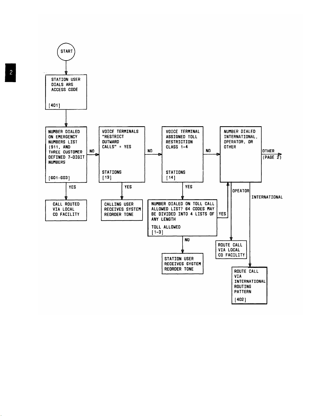
Figure 2-1. Automatic Route Selection Flow Chart (Sheet 1 of 2)
2-32

Figure 2-1. Automatic Route Selection Flow Chart (Sheet 2 of 2)
2-33

Figure 2-2. Automatic Route Selection Routing Pattern
2-34

CALL ACCOUNTING SYSTEM (CAS)
Description
Call Accounting Systems help customers control telephone use and manage associated costs.
The following AT&T Call Accounting Systems are available for use with System 25:
● Models 200, 300, 500, and 2000–AT&T PC 6300 Software Based System
The System 25 Station Message Detail Recording (SMDR) interface provides several
customer options for obtaining telephone use and cost information:
● Direct output to a printer (Refer to the SMDR feature description for additional
information.)
● Direct output to a AT&T PC 6300 Personal Computer equipped with a CAS software
package (i.e., Model 200, 300, 500, and 2000) that calculates the cost of calls and
provides basic and sophisticated call reports.
CAS Models 200/300/500/2000
After a telephone call is completed, System 25 sends a call record to the AT&T PC 6300 via
the SMDR interface channel. The PC must be equipped with CAS software.
Call records are collected by the PC and held in a buffer until they are processed. When a
call record is processed, a cost is calculated and assigned to it. That cost, along with other
call record information, is then stored on a hard disk for subsequent retrieval.
Two modes of operation are available for PC 6300 operation:
●
Dedicated Mode: The PC is dedicated to one and only one task–processing call
records.
Multi-Function Mode: Allows the user to print reports, edit files, and run other
●
PC-based programs while the CAS continues to collect and buffer call records in the
background. The user must enter the Dedicated Mode to process calls and generate
reports.
The CAS performs three main functions; (1) call record processing, (2) report generation, and
(3) CAS system management.
In addition, a limited directory lookup and message center is
provided. The following is a brief description of each function:
1. Process Calls: Involves screening call records, calculating the cost of valid calls,
and storing the call records.
2. Generate Reports: Allows the user to print the stored call record information
organized in one of several different ways. Users can select a report or setup their
own special combination of reports from the following:
● Summary Reports— A collection of reports that condense and summarize
call record information by total number of calls, duration, and cost. The
reports can be organized by department, call type, cost center, trunk,
extension, cost, duration, time of day, date, and account code.
● Organization Detail Report–A detailed report of each call record in the
system, sorted by department, cost center, and extension.
2-35

Selection Report—This report can contain at a user’s option, summary or
detailed information based on any combination of the following items: time
of day, date, cost, duration, extension,
number, call type, department, or cost center.
access code, account code, dialed
Account Code Detailed Report–
account code. This report can be used for billing clients for calls made in
their behalf.
Preselected Reports—
include any of the above mentioned reports. These reports can run upon
request or at a specified time and date.
3. System Management: All
include editing the table of departments, cost centers, and extensions; setting up
account codes; defining preselected reports; and keeping call rate information up to
date. System configuration may be changed.
CAS of changes in System 25 (e.g., dial access codes, trunks) or changes in charge
rates.
passwords, deleting call records, determining call processing options, and
performing various disk maintenance operations.
4. Directory Lookup and Message Center: Allows the user to look up anyone by
last name, first name, or extension. Messages can be recorded for individuals and
can be printed or displayed.
Additional information on the
description.
The following table summarizes
System housekeeping may also be performed. This includes establishing
SMDR call record output is provided in the SMDR feature
CAS station and account code capacities.
Allows up to five predefine reports which can
OWS the user to perform several functions. These
A detailed report on call records sorted by
This allows the user to inform the
AT&T CALL ACCOUNTING SYSTEMS
CAS Model Stations
200
300
500
100
150
500
2000 2000
Refer to the CAS documentation for additional information.
Considerations
The CAS provides customers with an efficient tool to control and manage their telephone
usage and costs.
analysis, and abuse control.
The information available can be used to facilitate cost allocation, traffic
Account Codes
5000
5000
5000
15000
2-36

Interactions
None
Administration
System:
● Send SMDR Records To SMDR Port (Yes, No) - Default = Yes
● Bill Call S Seconds After Last Digit Dialed (10-255) - Default = 40.
Hardware Requirements
Requires an AT&T PC 6300 equipped with CAS Model 200, 300, 500, or 2000 applications
software.
2-37

CALL COVERAGE—GROUP
Description
Allows calls to covered stations to be redirected to a group of covering stations.
A total of 32 CaIl Coverage Groups may be assigned. Each group maybe covered by up to
eight call coverage receivers (buttons). There is no limit on the number of covered users
(senders) that each Call Coverage Group can include, but a covered user can be assigned to
only one Call Coverage Group. Each call coverage receiver must have a multiline set
equipped with a Cover (COVER-GRP) button. A covering set may be assigned more than one
COVER-GRP button for the same or different groups.
Senders maybe either single-line or multilane voice terminals.
When a call arrives at a voice terminal that has group coverage, the COVER-GRP button
status LED at the covering voice terminals will flash. Covering voice terminals will begin to
ring after a specified number of rings at idle covered voice terminals. If there is no idle
COVER-GRP button, the call will not receive coverage treatment and the called station will
continue to ring.
Ringing may be turned off at covering stations at each covering button as desired (not
recommended). If this option is selected, a flashing status LED will be the only indication
received at the covering station. In addition, Call Coverage ringing may be turned off on
internal calls (if desired) on a system-wide basis.
The covering user can use the Line Selection (Preelection) feature to answer covered calls
even before any audible alerting has begun at the covering user’s terminal. This is useful if
the user knows that the covered party is unavailable.
A covered voice terminal may elect to have calls covered while it is busy on another call.
Calls directed to an idle button on a covered multiline voice terminal will start ringing at the
covering terminal after a single burst of ringing at the covered voice terminal. If there is no
idle Cover button on the covering voice terminal, the call will not receive coverage treatment.
Calls directed to a busy single-line voice terminal will start ringing immediately at the
covering terminal. If there is no idle Cover button on any covering terminal, either
individual or group, the call will not receive coverage and the calling party will receive Busy
Tone.
Calls sent to coverage will continue to ring at called single-line sets but will cease ringing at
multiline sets.
button, and that button’s status LED continues to reflect the status of the call. In
particular, covered calls to multiline sets remain available and can be entered by the called
station.
If a covered station activates the SEND ALL CALLS button, calls will be directed to
coverage immediately or after a single-ring reminder, as administered.
A station can provide (or receive) Individual Call Coverage (see Call Coverage-Individual)
and also be a member of a Call Coverage Group (sender
station, provided both Individual and Group Call Coverage, will first ring at the Individual
Coverage station and then after a second delay cycle if still unanswered will ring at the
Group Coverage station.
In the latter case, the calls will remain on the incoming call appearance
or receiver). Unanswered calls to a
Calls from a covering station to a covered station will not be covered unless the covered
station has additional coverage.
provides coverage.
This is an important consideration when the attendant
2-38

Considerations
Call Coverage provides a way to redirect calls to alternate answering positions. The feature
is versatile enough to permit suitable alternate answering arrangements for virtually every
level of employee.
Special functions, such as the Send All Calls feature, accommodate the
day-to-day variations that occur in an employee’s work schedule.
Interactions
● Attendant Console: If the attendant is a receiver for a Call Coverage Group and
extends a call (using the Start button or DXS Console) which is unanswered to a
member of the group, the call will return on the Return-on-Don’t-Answer (RTN-DA)
button, not on the attendant’s COVER-GRP button.
● Automatic Intercom: Auto-Intercom calls do not receive call coverage.
● Call Coverage—
Individual: Unanswered calls to a station, provided both
Individual and Group Call Coverage, will first ring at the Individual Coverage station
and then after a second delay cycle if still unanswered will ring at the Group
Coverage station.
● Call Coverage/Station Hunting: A call to a busy single-line voice terminal which
is both a member of a Station Hunting group and a Call Coverage sender will first
hunt for an idle station to service the call. If none is available, the call will be sent
to coverage.
● Call Pickup: Call Pickup is independent of call coverage. When a call is answered
via Call Pickup, all Cover buttons associated with the called party go idle.
● Direct Group Calling (DGC): A call to a DGC group member will receive coverage
if the member is also a Call Coverage sender. Calls to a busy DGC group do not
receive call coverage.
Instead, after a predefined number of rings, the call will be
transferred to delay announcement (if provided), or ringing will be transferred to all
button appearances of the line.
● Exclusion: If a call coverage receiver invokes Exclusion after answering a coverage
call, all other terminals (including the attendant and the covered station) are
excluded from the call. The covered user cannot enter the call until EXCLUSION is
pressed a second time by the covering user.
● Hands-Free-Answer On Intercom: An incoming (inside) call will not receive call
coverage if auto-answer is activated, since the set will answer the call (whether the
user is present or not.).
● Personal Dial Codes: Calls directed to a station because another non-floating PDC
is logged in there
do not receive the coverage treatment of the logged-in station.
Such calls return to their home station and receive that station’s coverage
(immediately upon return).
receive the
same coverage treatment as any other calls to the logged-into station.
Calls to logged-in
floating PDCs, on the other hand,
They, of course, have no home station to return to.
● Personal Lines: Personal line calls receive the coverage of the principal (owner)
station for that line. Other line appearances (even if administered to ring) will not
receive coverage.
● Tie Trunks: Tie Trunk calls directed at a user with call coverage receive normal call
coverage treatment.
2-39

Administration
System
●
Provide Call Coverage ringing on internal calls (Yes, No) - Default = Yes (Covered
calls will flash but not ring at covered stations on internal calls if = No)
● Number of rings before call coverage ringing starts on no answer (0-31) - Default = 2
(Call Coverage button’s status LED on covering terminal begins flashing immediately
in all cases. )
Voice Terminal: (Station Port)
●
Coverage Sender group number (1-3) - Default = 1
●
Provide Call Coverage ringing on no answer (Yes, No) - Default = Yes (otherwise,
flashing LED is the only indication received at the covering station)
●
Provide Call Coverage ringing on busy (Yes, No) - Default = Yes (otherwise, flashing
LED is the only indication received at the covering station)
● Call Coverage Receiver button
-
Group Number (1-32)
—
Allow Ring At Destination (Yes, No) -
Default = Yes (otherwise, flashing
LED is only indication received at the covering station).
Hardware Requirements
None
2-40

Description
CALL COVERAGE—INDIVIDUAL
This feature is very similar to Call Coverage–Group.
a one-on-one type coverage.
An Individual Cover (COVER IND) button can be assigned on multiline voice terminals to
cover calls to a specific (single) voice terminal.
calls by pressing COVER-IND. Each button can be programmed to ring or not to ring. If
ringing is selected, the covering station will begin ringing after a specified number of rings
at the covered station. When the call is answered at the covering station, the call remains
accessible at the call appearance button of multiline voice terminals, but is no longer
accessible at single-line voice terminals.
multiline voice terminals will stop ringing. Single-line voice terminals continue to ring.
Covered calls will appear on the COVER-IND button; call types except Automatic Intercom
calls be covered.
A multiline voice terminal may be equipped with a Send All Calls (SEND ALL CALLS)
button to transfer ringing to the covering stations.
equipped with a similar button, which will cause all Cover buttons on that terminal to be
considered busy by the system. Pressing SEND ALL CALLS lights that button’s status LED
and transfers ringing immediately with no ringing or with a single burst of ringing at the
called voice terminal (optional) on any future call eligible for coverage treatment. If there is
no idle Cover button on any covering voice terminals, the call will not receive coverage and
will ring at the called station.
button a second time.
Each Cover button at a covering station represents one covered voice terminal. If more than
one voice terminal is to be covered, multiple buttons are required, one for each station
covered. A covering voice terminal may be assigned multiple COVER-IND buttons for a
particular station to cover multiple simultaneous calls to that station. The first button will
track the first call, the second button, the second call, etc.
The Send All Calls feature is deactivated by pressing the
When the specified number of rings has occurred,
The primary difference is that this is
The covering station can answer covered
Any covering station may also be
Up to eight COVER-IND buttons can be assigned for each covered station. Up to 31 stations
may receive Call Coverage—Individual.
A voice terminal can receive both Individual Call Coverage and Group Call Coverage.
Refer to Messaging Services for a description of Call Coverage—Message Waiting service
which allows the covering station to control the status of the covered user’s Message LED.
Calls from a covering station to a covered station will not be covered unless the covered
station has additional coverage.
provides coverage.
Considerations
Call Coverage provides a way to redirect calls to alternate answering positions. The feature
is versatile enough to permit suitable alternate answering arrangements for virtually every
level of employee.
day-to-day variations that occur in an employee’s work schedule.
Special functions, such as the Send All Calls feature, accommodate the
This is an important consideration when the attendant
2-41

Interactions
Attendant Console: When a coverage call
attendant receives a single burst of ringing.
rings at a busy Attendant Console, the
If the call is still unanswered when the
attendant hangs up, the Attendant Console will resume ringing.
Call Coverage—Group: Unanswered calls to a station, provided both Individual
and Group Call Coverage, will first ring at the Individual Coverage station and then
after a second delay cycle if still unanswered will ring at the Group Coverage station.
Direct Station Selection (DSS): Calls placed via a DSS button to a user with
Individual Call Coverage will receive call coverage. When a DSS button is used to
activate the busy-to-idle reminder for the user, the reminder is returned only when
the user becomes idle, not when an associated coverage user becomes idle.
Exclusion: If a covering station answers a coverage call and then invokes Exclusion,
all stations including the covered one, are excluded from the call.
Hold: May be used to place a coverage call on hold. The COVER-IND button’s status
LED winks at the covering station and the call appearance’s status LED winks at the
covered terminal. The held call will automatically leave the coverage terminal if
picked up by the covered user. The covering station will be unable to reenter the call.
Transfer: When a covering station transfers a covered call to another station, the
call will no longer appear at the covering station’s Cover button, though it still will
appear at covered multiline stations.
Administration
Voice Terminal: (Station Port)
● Individual Call Coverage button (button function # 12)
—
Individual Coverage PDC (l-9999)
—
Individual Coverage Delayed Ring (Yes, No).
Hardware Requirements
None
2-42

Description
CALL FOLLOWING (FORWARDING)
Allows users who are away from their phone
to receive calls at another phone, The feature
is functionally equivalent to Call Forwarding.
Users can login their PDC at another voice terminal and receive their calls at that terminal.
Logging in a PDC at a terminal automatically logs the PDC out at any other terminal.
PDCs will always have an associated home terminal. If a PDC is not logged in anywhere,
calls to the PDC will ring at the home terminal.
Logging in a FPDC automatically logs the FPDC out at any other voice terminal. However,
logging out a FPDC does not log the FPDC in at another terminal. Calls to FPDCs not
logged in at a terminal may be directed to the attendant (administrable and strongly
recommended).
When a PDC is logged in at another terminal (away terminal), dialing the PDC from the
away terminal directs the call to the PDC’s home terminal.
To log in a PDC, the user goes off-hook at the “away” terminal, enters “**” and their PDC
twice. The PDC logout procedure is similar; after going off-hook and receiving dial tone, the
user enters “**” followed by their PDC and then by a “O.” A “**O” entered at a voice
terminal will log out all PDCs and FPDCs logged in at that voice terminal.
Confirmation Tone is returned to a user who completes the procedure correctly.
The following call types or features are voice terminal oriented (associated with stations
rather
than PDCs) and do not follow a user who logs in at another terminal.
●
Automatic Intercom Calls
●
Directed Night Service calls
●
DGC Group Calls
●
DSS Calls
●
Manual Signaling
●
Message Waiting
●
Outward/Toll Restriction.
●
Personal Line Calls
Considerations
Call Following provides maximum flexibility to system users who are away from their voice
terminals. In addition, visitors can receive calls by logging in an assigned FPDC.
Call coverage treatment at the away station is not the same as that given to calls directed to
the away station.
See Call Coverage feature descriptions for additional information.
2-43

Interactions
Refer to the Personal Dial Code feature description.
Administration
None
Hardware Requirements
None
2-44

Description
CALL PARK
Allows
system.
.
a user to place a call on hold and then pick up the call from any voice terminal in the
It is used in three typical applications:
●
Call Park: A user places a call on hold and then picks it up at another voice
terminal
●
Meet-Me-Conference: A conference member places
the conference on hold and
pages another employee to join the conference.
●
Transfer: A user places a call on hold and then pages
another employee to pick up
the call
Call Park allows a user to move a held call to a “parked” position by dialing the Call Park
code (*5). The call can subsequently be retrieved from any voice terminal by dialing the Call
Park retrieval code (*8) and the PDC of the parking station.
In addition, any user active in
a conference involving fewer than five members may park the conference, so that another
user may join the conference.
A multiline voice terminal user may invoke Call Park by pressing HOLD to place a call or
conference on hold, then pressing an idle System Access button and dialing *5. A single-line
voice terminal user may invoke the feature by pressing the switchhook to place the call or
conference on hold, then dialing *5. After dialing *5, the user receives Confirmation Tone
and then Recall Dial Tone if the call is successfully parked. If the call cannot be parked,
Reorder Tone is received. In the latter case, to return to the held call, press the held call
button (multiline sets) or flash the switchhook (single-line sets).
The parking station may return to a parked call or conference without affecting the park
state. The multiline voice terminal user may return by pressing the held call button. The
single-line user may return by pressing the switchhook.
When the single-line user goes on-hook, the parked call is removed from the terminal and
cannot be reentered.
To retrieve a parked call, a user must obtain system dial tone, dial *8 and then dial the PDC
of the station that parked the call. If the call is not retrieved within 2 minutes the call will
return to the user that parked the call.
A call may be parked by the attendant using the same procedure as a multiline voice
terminal. In addition, if the Attendant Position is equipped with a DXS Console, up to eight
additional calls may be parked by dedicating any eight of the console DSS buttons to the call
park function.
A call may be parked using the DXS Console by pressing one of the dedicated
Call Park buttons. The status LED of the parked line on the Attendant Console winks and
the status LED of the Call Park button on the DXS Console lights steadily.
A call parked by the attendant using the same procedure as a multiline voice terminal will
return to the Attendant Console’s System Access button if it is not picked up within 2
minutes. A call parked with the DXS Console which is not picked up within 2 minutes will
return to the RTN-DA button on the Attendant Console, in the same manner as any other
unanswered call.
2-45

A call parked with the DXS Console is retrieved by dialing *8 and the access code assigned
to the dedicated DXS Console Call Park button.
Each voice terminal user (except the attendant) can only park one call at a time and a
maximum of 24 calls can be parked in the system at one time. A call is no longer parked
when it is answered, returns to the parking terminal or is abandoned by the caller.
Considerations
Call Park can be used whenever a user engaged on a call needs to go elsewhere and obtain
information, and wishes to complete the call from another terminal. Call Park also allows
users to answer a call from any voice terminal when paged.
Interactions
● Attendant Direct Extension Selection: Station-To-Station calls cannot be parked
via the Call Park buttons on the Attendant DXS Console.
● Attendant Position Busy: A call parked by an inactive attendant will return to
the inactive attendant on the button the call was parked on if the call times out.
● Conference: Parked conference calls do not return to the parking voice terminal.
They remain parked.
Call Park may be used to place a conference on hold if it
contains fewer than five parties.
● Exclusion: A call cannot be parked, and a parked call cannot be answered, if the
Exclusion feature is invoked on that call.
● Intercept Treatment With Reorder Tone: An unsuccessful attempt to park a
call due to misdialing or attempting to park more than one call at a voice terminal
results in Reorder Tone.
● Music-On-Hold: Parked calls (except conferences) receive music.
● Outward Restriction (see
“Calling Restrictions”): If the parking station is
outward restricted, the Recall Dial tone following a successful parked call cannot be
used to avoid restriction.
● Personal Line: A parked Personal Line is bridgeable by any user with a button
appearance of that line.
Bridging on to the connection does not answer the parked
call. The parked call will not return to the parking voice terminal user in this case.
● Toll Restriction: (see “Calling Restrictions”) If the parking voice terminal user
is toll restricted, the Recall Dial tone following a successful park cannot be used to
avoid the restriction.
Administration
Attendant DXS Console:
● Assign Call Park buttons.
Hardware Requirements
None
2-46

CALL PICKUP
Description
Allows a user to answer a call ringing at another voice terminal. There are two forms of
Call Pickup; (l) Directed and(2) Group.
Directed Call Pickup:
Directed Call Pickup allows calls to any other terminal, including Automatic Intercom calls
and calls ringing at coverage buttons to be picked up by a user by dialing the Call Pickup
code (*7) and the ringing terminal’s PDC. Picked-up calls remain accessible at the call
appearance button of multiline terminals,
but are no longer available at single-line
terminals.
A ringing call can be answered at a busy
switchhook, which will
place the current call on hold, dialing *7, and the ringing voice
single-line voice terminal by pressing the
terminal’s PDC.
Group Call Pickup:
Group Call Pickup permits calls to another terminal in the pick up group to be answered.
Any call, including Automatic Intercom calls, is eligible for Call Pickup.
A member of a Call Pickup Group can answer any call to any other member of the group by
dialing the Group Call Pickup code (“70)
Up to 16 groups (with up to 16 voice terminals in each group) can be set up. Each Call
Pickup group can have a maximum of two simultaneous ringing calls eligible for Call Pickup
treatment at a time, and the calls are picked up in order of arrival. A user can be assigned
to
only one Call Pickup Group.
If
the picked-up call was to a multiline terminal, the called terminal can still enter the call.
If
the called terminal was a single-line terminal, it cannot enter the call once it is picked up.
Call Pickup cannot be invoked after the
After a call pick up attempt has been
call has been answered.
made, Reorder Tone is heard if no eligible calls are
ringing.
Considerations
With Call Pickup, users do not have to leave their own voice terminal to answer a call at a
nearby voice terminal.
Instead, a user simply lifts the handset and dials an access code.
This allows calls that may go unanswered to be handled quickly and efficiently.
Interactions
● Call Coverage: When a call is directed to a coverage station and the call is
answered via Call Pickup, all Cover buttons associated with the call go idle.
● Personal Line: After a call is picked up from a Personal Line (PERS LINE) button,
the called terminal can still enter the call.
2-47

Administration
Voice Terminal: (Station Port)
● Assign Call Pickup Group Number (1-16, None) - Default = None.
Hardware Requirements
None
2-48

CALL PROGRESS
TONES
Call Progress tones provide audible feedback on the status of calls during call set-up.
● Busy Tone: A slow pulsed tone indicating that all facilities for answering the call
are in use.
● Call Waiting (Camp On) Tone: A single short tone to a busy terminal indicating
that a second call is waiting.
● Confirmation Tone: Three short tones indicating that the system has accepted the
instruction entered or that your ARS queued call is being placed.
● Dial Tone: A steady tone indicating that dialing or feature activation can begin
● Dialing Feedback: Indicates that a digit has been dialed.
● Preferred Route (Queuing) Tone (ARS): Five short tones. Indicates no facility
is currently available to place your call. If you remain off-hook, your call will be
placed as soon as a facility is available.
● Reorder Tone: A fast pulsed tone indicating that all trunks are busy, a dialing
error has occurred or that the terminal is restricted from mak
● Ringback Tone: Indicates that a called terminal is ringing.
ing this call.
For additional information, refer to Section 8, “Tones”.
2-49

CALLING RESTRICTIONS
Description
Allows restricting designated voice and data terminals from making certain types of calls.
Available restrictions are:
● Outward Restriction
● Toll Restriction
● Facility Access Restriction
● ARS Restrictions.
Note that all these restrictions apply to stations, not PDCs.
Outward Restriction:
When outward restricted, a station will be unable to place any outside calls. The station will
be able to answer incoming calls and place and receive inside calls. A station that is
outward restricted will be unable to use Automatic Route Selection to place external calls
except to the emergency numbers.
Toll Restriction:
Allows calls by restricted terminals to be made based on as many as the first six digits of
the number called (after the facility access code). If a user is toll restricted, the user can
make outgoing calls only to those numbers which are on the Toll Call Allowed (TCA) Lists to
which it has access.
six characters. ) The system manager can establish up to
contain from 1 to
TCA entries must be in the form NNX or NPA-NNX (exactly three or
4 individual lists. A list can
64 entries provided that the total of all four lists does not exceed 64. One
character “.” can be specified as a wild card character in place of the last 1, 2, or 3-digits
(e.g., “NN.”, “N..”, or “...”
) of the NNX code, but not in the NPA code. When this character
is used, any character in the dialed number appearing in that position is acceptable. Those
stations assigned Toll Restriction Class 1 have access to all four TCA Lists; Class 2 stations
just lists 2 through
4, Class 3 stations just lists 3 and 4, Class 4 stations just list 4. The entry
of an area code followed by “...” on a TCA List allows access to all office codes in that area.
To allow calls within a customer’s local area, individual office codes are entered; this allows
the customer to restrict toll calls within the local calling area. NPA-NNX entries allow
specific office codes to be called within an area.
Note, NPA only entries are not permitted
(use NPA-...).
Note that stations that are toll restricted are only toll restricted on CO trunks (type 701 and
801 ) or when they use the ARS feature.
They will not be toll restricted when they dial
access (or button access) any other type of trunk (e.g., FX, WATS, or Tie trunks).
Facility Access Restriction:
Any station may be denied dial access to the local CO and/or to all other pooled facilities (as
a group). A station so restricted may only access those facilities via the Automatic Route
Selection feature
provided the FRL of the station is equal to or greater than that of the
:
ARS route.
ARS Restriction:
Special restrictions on each station may be imposed when the call is routed by the ARS
feature. Facility Restriction Levels (FRLs) are used to restrict access to trunk groups. An
FRL is a single digit (O, 1, 2, 3). A terminal assigned an FRL of O has the least privileges, a
terminal assigned an FRL of 3, the most.
An FRL is also assigned to each route in each
2-50

ARS routing pattern. The terminal’s FRL must be equal to or greater than the routes FRL
in order to use that facility.
Considerations
Restrictions are used whenever it is necessary to restrict certain users from accessing
designated facilities.
A typical application is to deny most stations dial access to all trunk
groups. This then, forces those stations to use the ARS feature, which should result in
reduced toll charges.
Interactions
● Automatic Route Selection: The use of the ARS feature will not allow users to
avoid restrictions.
Outward Restriction and Toll Restriction, when administered,
prevent calls originating at associated voice terminals from routing via ARS.
Facility access restrictions are circumvented.
● Personal Lines: Personal Lines are subject to the toll restriction options of the
stations on which they appear.
● Pooled Facility-Button Access: Toll restricted stations receive standard toll
restriction treatment on all Pooled Facility access buttons.
● Repertory Dialing: A user cannot use Repertory Dialing to access a number that
he/she is restricted from dialing.
● Speed Dialing: A user cannot use Speed Dialing to access a number that he/she is
restricted from dialing.
● Transfer: Anon-restricted user (typically the attendant) can transfer a CO trunk to
an outward restricted or toll restricted station, giving the station outward service.
The toll restriction class of the transferring station will apply for calls placed over a
transferred trunk.
Administration
Voice Terminal: (Station Port)
● Restrict access to CO trunk pool (Yes, No)- Default = No
● Restrict access to all other trunk pools (Yes, No) - Default = No
● Restrict outward calls (Yes, No) - Default = No
● ARS Facility Restriction Level (Level Number O-3) - Default = 3
● Specify Toll Restriction Class (Class Number 1-4, None) - Default = None (not
restricted).
Automatic Route Selection:
● Route Facility Restriction Levels.
Hardware Requirements: None
2-51

COMMAND MODE AND DATA TERMINAL DIALING
Allows data terminal users to originate data calls or view data port options.
(Refer also to the overview of the system’s data features provided in the “Data Calls and
Services” description.)
Command Mode supports digital data endpoints connected via Asynchronous Data lJnits
(ADUs) to ports on a Data Line CP (TN-726).
Command Mode is invoked from a data terminal in the idle (on-hook) mode by:
Terminal Optioned For Autobaud
Enter Break followed by Return
The terminal then displays the Command Mode menu:
<place Data call>
Menu items are chosen either by positioning the cursor under the desired item (by typing
“space” characters) and entering a Return, or by typing the upper-case character in the
menu field (e.g., type “D” to enter terminal dialing or “O” to view options). Once a user has
entered Command Mode, the terminal is considered off-hook and busy to incoming calls until
it returns to the idle mode.
Place Data Call:
Refer to the Terminal Dialing description below for information on how to dial from your
terminal. Once a data call has been set up, the “Command Mode Character” (see Options)
must be sent to terminate the data call and return to idle mode. If a data call is not
answered the caller must disconnect by sending a Break.
Options
If the Command Mode menu item “Options” is chosen, the terminal displays the data port’s
administered options. These options can only be changed via the SAT. System default
values for each option are also shown. The display shows the following
Terminal Not Optioned For Autobaud
I
<Options>
Enter Break
OPTIONS
Speed (highest)
Parity
Mismatch
Local Echo
Answer Text
Connect Indication
Command Mode Char
SELECTED
[current value]
[current value]
[current value]
[current value]
[current value]
[current value]
[current value]
2-52
DEFAULT
Autobaud
Even
off
On
On
Yes
Br-Br

Table 2-E provides a listing of the Data Port’s (TN-726) administrable options.
TABLE 2-E. Permissible Data Port (TN-726) Options
OPTION
Speed (61-68)†
Parity (69) Used only when data terminal requires specified
Allow Command Mode (70) On or Off. Must be On for Command Mode
Permit Mismatch (72) On or Off. Allows two data endpoints to
Local Echo (73) On or Off (Half or Full Duplex). Determines whether
Answer Text (75) On or Off. Enables call progress messages to be
Connected Indication (77)
I
Autobaud, Low *,
I
parity
(i.e., Command Mode Menu display). Not shown on
options list.
communicate at different rates. For use with host
computers running special communications packages
(only).
characters from the data equipment will be echoed by
System 25 during Command Mode.
displayed at the called data endpoint.
Yes or No. Yes indicates that users who have
Command Mode enabled will receive the
“CONNECTED” message when a connection has been
established. If Command Mode is disabled, the Data
Line port control lead will be “raised” when a
connection is established. Usually set to “No” for
host computer endpoints.
DEFINITION
300, 1200, 2400, 4800, 9600, 19200
Command Mode One Long Break or Two Short Breaks
Disconnect Character (74)
* A terminal whose baud rate is low cannot use the Command Mode feature. Call
origination at this terminal must be via One-Button-Transfer To Data.
† Numbers in () indicate the action numbers used to administer data port options.
2-53

Data Terminal Dialing
Allows a user to originate data calls from a data terminal. Voice terminal dialing and call
progress tones are replaced by keyboard dialing and call progress messages. The message
“DIAL:’’ prompts the user to enter the called number from the keyboard, and “RINGING” or
“DIALING . .. COMPLETED” informs the user that the dialed number is being called.
Table 2-F provides a list of the call progress messages.
Dialed Characters
In addition to digits and the “#” and
“*” characters on the touch-tone pad, the dialed
number may contain the following special characters:
● The characters “(” “)” “-”
and SPACE may be used to improve legibility. These
characters are ignored.
● The “%” or “,”
characters may be used to cause a 1.5-second pause in dialing.
(multiple characters can be used).
● The “$” (mark) character indicates that the remaining digits are for end-to-end
signaling.
● UNDERLINE or BACKSPACE characters may be used to correct previously typed
characters on the same line.
● The “@” character may be used to delete the entire line and start over with a new
DIAL: prompt.
Each line of dialing information may contain up to 27 characters. Note that all of the
dialing information, including pauses and ignored characters, must be typed on a single line
following the DIAL: prompt and terminated by Return.
Dialing Correction:
The backspace character (BS key or Ctrl-H keys) or underscore “ _“ may be used to cancel
the previously entered character.
multiple backspace or underscore characters.
More than one entered character may be deleted by using
The “@” character may be used to delete the
entire line of entered characters.
Pause:
To assist the completion of off-premises calls, the pause characters “%” or “,” may be used.
A pause character may be used to help ensure the receipt of dial tone before continuing to
dial. Each “%” or “,”
causes a fixed delay of one and one-half (1.5) seconds. Pause
characters may be used consecutively if a longer pause is required. Note that System 25
cannot detect tones, such as a second dial tone for end-to-end signaling.
End-to-End Signaling:
Data connections to off-premises destinations require that a conversion resource be inserted
into the connection. Occasionally it is necessary to send additional tones to the remote
endpoint after the connection is established to signal the remote equipment. A “mark”
character must be included on the DIAL: line to indicate to call processing that the
remaining digits are to be sent to the far end prior to insertion of the conversion resource
into the connection. The “mark” character marks the boundary between the digits dialed to
reach a distant endpoint, and the digits used by that distant endpoint after it has answered.
Pause characters may and usually should follow a
“mark” character. An example using a
“mark” character and several pause characters is shown below. Dashes are included for
readability.
2-54

Examples of dialing are as follows:
● DIAL: 3478
● DIAL: 9-1-(201)-946-8123,,,5678
● DIAL: 9% 946-8123%% $5678% 137% 110
Call Disposition:
Call progress messages corresponding to call progress tones provided to voice terminals are
listed in Table 2-F. The message supplied (indicating reorder,
busy, ringback) depends on
the disposition of the call.
1. When ringback is received the displayed message is
only). For outside calls, the corresponding call progress
“RINGING” (internal calls
message is
“DIALING . . . .“.
2. If the endpoint answers, the displayed message is “ANSWERED” (internal calls
only).
outside calls, when the system has finished dialing, the message “COMPLETED” is
displayed.
3. If the handshake fails because a connection cannot be
endpoints (e.g., a port optioned at 9600 baud attempts to
resource
“INCOMPATIBLE FAR END”, “DISCONNECTED” and the data endpoint goes
on-hook.
If the far end does not answer, the caller must press Break to terminate the call attempt.
If the disposition of the call is such that TRY AGAIN or BUSY (indicating reorder or
intercept and busy respectively) is received, the switch sends “DISCONNECTED” to the data
terminal which goes on-hook.
Answering Endpoint:
When the dialed end point is alerted, the user receives
terminal will auto-answer if it is turned on. If the handshake succeeds a data connection is
established and the “CONNECTED” message is displayed if so optioned. If the handshake
fails the user receives
endpoint goes on-hook.
Then, if the handshake succeeds a data connection is established. For
established between
talk to a conversion
that can only talk at 300 or 1200 baud),
the user receives
“INCOMING CALL-” (the called
“INCOMPATIBLE FAR END, DISCONNECTED” and the data
2-55

TABLE 2-F. Call Progress Messages for Data Terminal Dialing
Displayed
Message Application Meaning
DIAL:
RINGING
BUSY
ANSWERED
TRY AGAIN
INCOMING CALL-* Receiving a call
PLEASE ANS-
DISCONNECTED* Call is terminated
CONNECTED, Call is connected
SPEED = NNNN
INCOMPATIBLE FAR END
DIALING . . COMPLETED Placing a call
PLEASE WAIT
BAD NUMBER
NO MODEM Placing a call
Placing a call Equivalent to dial tone. Enter any
Placing a call
Placing a call Equivalent to busy tone. Called number is
Placing or
receiving a call
Placing a call
Placing a call from Originating voice terminal user has
a voice terminal
Placing a call
Placing a call Call queued.
Placing a call
required facility number followed by the
dialed number and a RETURN.
Equivalent to Ringback Tone. Called
number (far-end) is being signaled.
Provided on internal calls only.
in use, or out of service. Provided on
internal calls only.
Notifies calling and called users that call
has been answered. Provided on internal
calls only.
Equivalent to Reorder Tone. System
facilities are currently not available or
invalid number.
Equivalent to ringing.
transferred call to data terminal using
One-Button Transfer to Data.
Call or call attempt is disconnected.
Notifies user that the call connection is
established and what the baud rate is.
[Provided that “Connection indication”
(Data Port Action
Notifies user that the handshake between
data end points has failed
Indicates off-premises call is being dialed
and completed.
Bad dialed number
No modem available for a call that
requires one.
#77) is enabled.]
* Bell sounds when message is displayed.
2-56

Considerations
Terminal Dialing allows users to place data calls from their terminals using the Terminal
Dialing feature and allows users to review the options administered for their data ports.
Interactions
● End-To-End Signaling: (See above text)
●
Modem Pooling: Data calls between analog and digital endpoints require that a
conversion resource (TN-758) be available. If one is not, the “NO MODEM” followed
by “TRY AGAIN” message will be displayed.
● Speed Dialing: Speed Dial codes can be dialed from data terminals.
Administration
Data Port: See “Permissible Data Port Options” Table 2-E above.
Hardware Requirements
TN-726 Data Line CP to support each digital endpoint.
TN-758 Pooled Modem CP to support data calls between digital and analog endpoints.
2-57

CONFERENCE
Description
Allows up to five parties, including the conference originator, to participate in a conference
call.
Multiline Voice Terminals:
Multiline voice terminal users can add another (external or internal) party by pressing the
CONFERENCE button. The first party is placed on Special Hold (indicated by a broken
flutter on the line appearance button) and the system selects an idle System Access button,
providing system dial tone.
The user may dial the desired number or select another facility
to dial the party to be conferenced-in. Subsequently, pressing the held line button completes
the conference.
If the facility to be added is busy or has invoked Exclusion, the conference
will be denied.
Users can conference up to two external facilities, and up to five parties in all. Any attempt
to add a sixth party will be denied.
This limit is for the conference as a whole. Other
conference stations are also prohibited from adding a third outside party or sixth party.
Single-Line Voice Terminals:
The single-line voice terminal user can establish a conference by momentarily pressing the
switchhook, which puts the first party= on hold, receiving Recall Dial Tone, and then dialing a
second party.
establishes the conference.
After connection to the second party, another press of the switchhook
A third press of the switchhook will drop the second party,
restoring the original call. The user cannot put a conference which he/she has established
on hold. Other internal conferees (multiline or single-line) may then add additional parties
to the conference up to the five party/two outside line maximum.
Considerations
The Conference feature allows voice terminal users to set up conference calls without the
assistance of the attendant.
.
Interactions
●
Account Code Entry: If more than one user attempts to associate an account code
with a Conference Call, the first to activate the feature will prevail.
●
Attendant Message Waiting: Pressing the Attendant Message Waiting (ATT
MSG ) button while on a conference call will be ignored.
●
Call Park: Call park may be used to place a conference on hold if it contains fewer
than five parties.
Parked conference calls do not return to the parking station. They
remain parked.
Extended Stations: An Extended Station counts as one of the two allowable
●
outside lines on a conference call.
●
Exclusion: Exclusion may be invoked before establishing a conference. If it is
invoked after the conference is established, all internal conferees will be dropped.
2-58

● Music-On-Hold: An outside line placed on hold when CONFERENCE is pressed
will hear Music-On-Hold, if provided. However, if the outside line is already part of
a conference, music is not heard.
● Off-Premises Stations (OPS): For conference purposes, an OPS counts as one of
the two allowable outside lines.
● Paging System Access: A paging zone may not be conference.
● Trunk-To-Trunk Transfer: Trunk-to-trunk transfers may be set up using the
Conference feature. The conference must include an incoming trunk call on either a
ground start, DID, or Tie trunk if it is to continue after all inside stations have
dropped off.
Administration
None Required
Hardware Requirements
None
2-59

CONFERENCE DROP
Description
OWS a voice terminal user to selectively drop a previously added party from a conference
A11
call.
On a multiline voice terminal, pressing the DROP button and then pressing the button
appearance of a conference party, drops that party from the conference. If all System 25
stations hang up on a conference with two outside lines, the outside parties will remain
conference (until one of them hangs up), if at least one is a ground start, tie trunk, or DID
trunk that has an incoming call. If not, the call will be terminated when the last inside user
disconnects from the conference.
A single-line voice terminal user after having established a three party conference can drop
the second party and retain the first party by pressing the switchhook.
Considerations
Conference Drop allows users to conference lines appearing on their terminals and then
remove them from the conference when appropriate.
A user should only drop parties that they
have added to a conference. If a user tries to drop
a party who previously added them to the conference, other parties may also be dropped.
Interactions
None
Administration
None Required
Hardware Requirements
None
2-60

DATA CALLS AND SERVICES
System 25’s data features provide switched data transmission at up to 19,200 bps (RS-232C
interface), and a 212A modern compatible conversion resource capable of handling data at
300 and 1200 bps.
The system provides switched connections between data endpoints. These endpoints include
data terminals, personal computers, multiport computers, and modems. Data endpoints are
either digital data endpoints or analog data endpoints.
Analog endpoints are connected to System 25 voice terminal or trunk port circuits through a
modem in the traditional manner.
circuits on the TN-726 Data Line CP. A data module (specifically, an Asynchronous Data
Unit - ADU) is required in place of the modem used with analog endpoints. Section
manual shows the connections supported and required connecting equipment.
Digital endpoints are connected to System 25 data port
4 of this
Data calls can be set up between data endpoints.
connections are straightforward;
only if the system is equipped with a conversion resource (TN-758 Pooled Modem Circuit
Pack or external modem pool). System 25 data calls from analog endpoints (including those
to digital endpoints) are set up in the traditional manner.
the procedures supplied with his/her modem.
dialed when calling a digital endpoint.
Call set-up from digital endpoints is facilitated by several data features:
Data Terminal Dialing, Modem Pooling,
Transfer To Data allows the user to place a data call from a voice terminal and then
transfer the call to an associated data terminal.
In the discussion that follows, it is important to understand the difference between analog
voice terminology and data terminology. Refer to the “Glossary” (Section 11).
The following provides a definition of a data call in terms of its contextual components. The
components are (1) data endpoints, (2) data endpoint states, (3) data call processing modes,
(4) connecting configurations, and (5) controlling features.
Data Endpoints
Data endpoints are composed of data equipment, a data module or modem, and a connection
to the switch via an analog or data port.
Dial Code (DDC). Analog data endpoints are addressed like other voice terminals, by their
PDCs. For the remainder of this description,
endpoints unless stated otherwise.
calls between analog and digital endpoints are possible
and One-Button-Transfer To Data. One-Button-
A digital data endpoint is addressed by its Data
Analog to analog and digital to digital
The calling party should follow
However, a Modem Request Code must be
Command Mode &
data endpoints will refer to digital data
Several different categories of data endpoints are supported. The categories have been
divided into two general groups, those having a DTE type interface, which encompasses
almost all of the data terminal devices, and a group of DCE interface devices (primarily
modems ). The groups have then been divided into categories based upon their functional
attributes. However, it must be noted that within each category, control interfaces may
vary. The following describes the categories and attributes of each:
1. DTE Devices
This group of data endpoints have one thing in common, their interface
configuration, although RS-232C control signal utilization varies significantly from
terminal to terminal. Some data equipment do not use any RS-232C control
signals; these require only BA (Transmitted Data Ready-Tx), BB (Received Data
Ready-Rx) and AB (Signal Ground) to function, while others require more RS-232C
2-61

control signals to operate. An ADU (Figure 2-6) can send Data Terminal Ready
(DTR) from the data terminal to the Data Line circuit and the Data Line circuit
can send a CD control signal to the data terminal. The signals Data Set Ready
(DSR), Clear To Send (CTS), and Received Line Signal Detector (DCD) are all
connected to the CD control signal in the ADU and available if required by the
data terminal. Refer to Section 8 (Port Specifications) for additional information.
Figure 2-3. Asynchronous Data Unit Interface Signals
The following categories are part of the DTE data endpoint group:
a. Data Terminal Without ASCII Keyboard
This category includes such devices as Fax machines, EBCDIC or Baudot
terminals, and receive only devices such as printers.
Once connected to an ADU data module and turned on, these data
endpoints appear on-line and available when they are turned on and
ready to enter the Setup mode on auto-answered calls (modes are
described below). These endpoints will display or print information
received after a valid connection has been established without additional
RS-232C control from that endpoint.
endpoints.
b. ASCII Data Terminal With Keyboard
This category can be subdivided into two classes: (1) basic terminals, and
(2) intelligent, programmable data equipment such as personal
computers. Basic terminals appear to the data port to be on-line and
available whenever they are turned on, thus ready to enter either the
Data Terminal Dialing mode, or to enter the Setup mode on calls
originating from a voice terminal or auto-answered calls.
Note that these are answer only
2-62

In the case of most personal computers, a communications program must
be executed in order for it to communicate with its own RS-232C port or
built-in modem. Once the communications software is running, further
operation will be similar to that of the basic terminal.
c. Host Computer Endpoint
A host computer endpoint is very
keyboard except that the host has many ports and the interface is usually
capable of supporting multiple speeds and more of the RS-232C control
signals. Front end communication software running in the host is
typically supplied by the computer vendor and is not designed to support
the Data Terminal Dialing feature,
origination through Automatic Calling Units (ACUs) which are not
compatible with Terminal Dialing.
communicating with the host is by calling from data terminals or
personal computers. Groups of host ports with matching characteristics
may be members of hunt groups (referred to as host port groups).
d. Analog Data Endpoint
Data endpoints with modems are referred to as analog data endpoints.
Modems connected via tip ring lines and use PDCs as extension numbers
rather than Data Dial Codes (DDCs). Station-to-station data calls to or
from this endpoint to or from digital endpoints require a modem
conversion resource to convert the endpoint’s analog data back to digital
format. Calls from digital endpoints terminating at an analog data
endpoint (i.e.,
resource inserted in the calling path. If the called endpoint should then
invoke One-Button-Transfer To Data, the conversion resource will be
released. Data calls originating from an analog data endpoint must first
enter a Modem Request Code before addressing a digital data endpoint.
This is required because the system assumes that a call originating from
a voice terminal will invoke One-Button-Transfer To Data. If the analog
data endpoint is not going to transfer to data, they must indicate this so
that a conversion resource will be included in the connection.
calls to a PDC), will automatically have a conversion
similar to a data endpoint with
Such software typically supports call
Thus, the primary means of
2. DCE Devices
This group of data endpoints consists primarily of modems. The modems are
connected to a data port from their RS-232C side. The data module must be
configured as a DTE interface to provide connectivity between the modem and a
data port. It is possible to simulate a DTE interface from an ADU data module
with a “null modem” type cable. This group of endpoints is important for users
that provide their own modems connected to dedicated trunks or private lines for
internal modem pooling.
Data Endpoint States
The data endpoint may take on three states: (1) off-line, (2) on-line (on-hook), and (3) on-line
(off-hook). Off-line is equivalent to a voice terminal being out of service. If a direct analogy
of on-line (on-hook) were made to voice calls, the terminal will always be available to answer
a call when it is turned on (this is similar to an HFAI voice terminal).
2-63

Data Call Processing Modes
Data calls differ both in signaling and call setup from voice calls. For this reason, a unique
set of data call processing modes have been defined to support data call operation in a
manner consistent with the characteristics of data terminals.
a. Off-Line Mode
The data endpoint is considered to be in the Off-Line Mode whenever the data
endpoint’s DTR signal is inactive (e.g.,
“turned off” ). The endpoint is considered
unavailable and calls to this endpoint will receive the “RINGING” message or
Ringback (indefinitely).
b. Idle Mode
The Idle Mode indicates that the data endpoint is in its on-line, on-hook state.
While idle, call processing will allow the endpoint to:
—
Enter either Data Terminal Dialing mode to originate a data call or enter
the Setup mode after a call is originated from a voice terminal (OneButton-Transfer To Data).
—
Autoanswer a data call and go into Setup mode.
The data endpoint remains in the Idle mode while the user is establishing a data
call from a voice terminal until One-Button-Transfer To Data is activated.
c. Command Mode
Command Mode enables the Data Terminal Dialing feature and allows the user to
view associated data port options. Command Mode may be entered by going offhook and pressing Break or Break-Return.
d. Data Terminal Dialing Mode
Terminal Dialing is a data feature accessed via Command Mode. It provides a
procedure to establish data calls without the use of a voice terminal. Terminal
Dialing supports both on-premises and off-premises data calls (with the support of
the System 25 Modem Pooling feature).
Dialed digits are entered from the data
terminal keyboard or host computer (using a program compatible with Terminal
Dialing protocol ). Call progress text messages are sent to the terminal in place of
call progress tones.
Upon completion of digit entry, Data Call Setup mode is
entered.
e. Data Call Setup Mode
Data Call Setup Mode is a transitional state entered after One-Button-Transfer To
Data, Terminal Dialing, or during auto-answer and exists during the handshake
between data ports.
If the endpoints are compatible and handshaking is successful, a data connection is
established. If handshake failure occurs, the user is notified and the data endpoint
returns to the Idle mode. Successful handshake must occur within 15 seconds of
answer at the called data endpoint. This implies that the voice terminal user must
invoke One-Button-Transfer To Data within 15 seconds after far end answer.
Similarly, if an originating voice user calls a voice terminal and both users
transfer to data, both ends must transfer within the
15 second time limit.
If the data endpoint is optioned for Command Mode permission, the data endpoint
will receive call progress text messages while in the Data Call Setup mode.
2-64

f. Data Mode
Data Mode is first entered after successful completion of Data Call Setup.
Transparent communication between connected endpoints is provided in Data
Mode.
Connecting Configurations
Refer to Section 4, ’’Connectivity”
for data equipment connections.
Controlling Features
It is possible to originate data calls from a voice terminal with all at a button or from data
endpoints that support Command Mode (i.e.,
ASCII data terminals with keyboards and host
computers). Several controlling features are provided to allow data endpoints and voice
terminals to set up data calls. The following briefly describes the Data Service features used
in controlling data calls.
a. Command Mode
Command Mode provides an interface to the Data Terminal Dialing feature and
permits the display of terminal options.
b. Data Terminal Dialing
Terminal Dialing provides call setup from terminals and host computers.
c. One-Button-Transfer To Data
One-Button-Transfer To Data is the preferred method of data call origination from
multiline voice terminals equipped with Data buttons and associated digital data
endpoints. The Data button is associated by DDC with a near end data endpoint.
A unique Data button must be provided for each DDC that the voice terminal is
capable of controlling.
Associated with each Data button is an LED that reflects
the status of data endpoints as follows:
● Dark–Data endpoint is idle
● Winking–Data endpoint is reserved (preindicated)
● Flashing-Data endpoint is being alerted of an incoming call
●
On Steady-Data endpoint on-line off-hook or reserved for another user
and busy.
Refer to the following feature descriptions for additional information:
. Command Mode And Data Terminal Dialing
. Modem Pooling
. One-Button-Transfer To Data.
2-65

DIAL PLAN
The dialing plan for System 25 is based on the concept that, whenever possible, calls should
be placed to individuals rather than to pieces of equipment. To implement this concept,
individuals are assigned Personal Dial Codes (PDCs) and are allowed to login those PDCs at
other voice terminals. There are two types of PDCs: assigned and floating. An assigned
PDC is associated with each voice terminal. Floating PDCs are administered at the SAT and
may (optionally) be associated with the attendant position when not logged in. Data
extensions on System 25 are assigned Data Dial Codes (DDCs).
Dial Code Assignments
System 25 dial codes are as follows:
Assignable System 25 dial codes may have 1, 2, 3, or 4 digits. These include voice terminal
PDCs, data terminal DDCs, Direct Group Calling (DGC) Groups, Paging Access, Attendant
Call Park, Night Service, Modem Request, Automatic Route Selection Access, Facility Access
(trunk group), and Dictation System Access codes.
System
25 fixed dial codes are:
● 0 for attendant access
● *1, *2, *3 are reserved for maintenance calls
● *4 Activate Make Busy for DGC group
● *5 Call Park
● *6 Deactivate Make Busy for DGC group
● *7 + O - Group Call Pickup Answer
*7 + PDC - Directed Call Pickup Answer
●
● *8 + PDC - Call Park Retrieval
● *9 Camped on Call Retrieval
● *O Account Code Entry from single-line voice terminals
** PDCPDC - login PDC
●
● **PDC0 - logout PDC
● **0 - logout all PDCs
● ##PDC - Call Accountability
● * - PAUSE character used in Speed Dialing and Repertory Dialing programming
● #100 -#189 - System Speed Dial Numbers
● #20-#26 - Personal Speed Dial Numbers
● #4 - Activate Program mode
● # - end of dialing.
The dial codes assigned in the system must be completely unambiguous. For example, a
dialing plan that contains the number
“20” cannot contain the numbers “2”, “200-209”, or
“2000-2099”.
2-66

PDC to Voice Terminal Association
During installation, each voice terminal is assigned one PDC which serves as its extension
number. These are termed assigned PDCs, and the associated terminals are called home
stations. Additional PDCs may be assigned in a system. These PDCs are termed floating
PDCs (FPDCs). At the customer’s option, floating PDCs may have the attendant position
assigned as their home station (i.e., calls to FPDCs will be directed to the attendant when
they are not logged in). A maximum of 200 assigned and 300 FPDCs may be allocated in a
system.
Data Dial Codes (DDCs)
At the time of installation each digital data endpoint will be assigned a Data Dial Code
(extension number). A maximum of 104 DDCs may be allocated in a system.
Direct Inward Dial (DID) Number Assignments
Each DID number is associated with a unique PDC (floating or assigned), a DGC group
number, a DDC, or a pooled facility access code. The number or code associated with a DID
number is the last 2, 3, or 4 digits of the DID number.
For example, the number or code
associated with the DID number “NNX-2157” will be 57, 157, or 2157.
All dial codes in the system which are associated with DID numbers should have the same
number of digits. However, their is no requirement that all PDCs, DDCs, DGC groups, or
facility access codes be associated with DID numbers.
Number Assignment Restrictions
For each assigned 3 or 4 digit code, a ten number block is
allocated space in memory. This
allocated block counts towards the PDC (200), FPDC (300), DDC (104) and dial code (600)
maximums for a system.
Voice Terminal Directed Features
Directed Night Service, DGC calls, Personal Line Calls, Manual Signaling, Station Message
Waiting, Automatic Intercom,
DSS, and Outward/Toll Restriction are associated with
specific terminals (stations), not with PDCs. This means that these features do not move
with a PDC when it is logged in at another voice terminal.
2-67

DICTATION SYSTEM ACCESS
Description
Permits access to, and control of customer-owned dictation equipment by voice terminal
users.
Dictation systems may be connected either via single-line voice terminal ports (the
preferred method) or via auxiliary trunk ports (if the dictation equipment requires a
separate contact closure for proper operation). The dictation system is accessed by dialing a
PDC oppressing a DSS button.
Considerations
Allows users to access and control shared dictation equipment.
Interactions
Direct Inward Dialing (DID): A DID number may match the dictation system access
code. This allows an outside caller to access the dictation equipment.
Administration
System:
● Requires a
port on a
port assignment on a ZTN-78 Tip Ring Line or TN-742 Analog Line CP. A
TN-763 Auxiliary Trunk CP must be used if the dictation equipment
requires a separate contact closure for proper operation.
Voice Terminal: (Station Port)
● Assign DSS access buttons as desired.
Hardware Requirements
Customer provided dictation equipment
Port on a ZTN-78, TN-742, or TN-763 CP, as required.
Refer to Section 4, “Dictation Equipment” for additional information.
2-68

Description
DIRECT GROUP CALLING (DGC)
Allows incoming calls to be directed to a specific
each including up to 10 members, may be set up.
Incoming calls on any trunk can be directed to a
for outgoing calls. This feature is referred to as
group of terminals. up to 32 DGC groups,
A terminal can be in only one DGC group.
DGC group. These trunks can also be used
“Incoming Calls Group” in the User Guides
(555-500-700 series).
Calls to a group hunt in a circular manner, starting at the terminal following the last one to
receive ringing (whether answered or not), and will ring at the next idle terminal in the
group. on multiline voice terminals the calls arrive on a System Access button.
If all group members are busy (off-hook), an outside call is queued and the caller receives
ringback tone.
number of rings.
If the system includes a delay announcement, it is played after a specified
The caller is subsequently put on hold (in queue) and will receive MusicOn-Hold if available. If the system is not equipped with a delay announcement, the call will
begin to ring at all line appearances after the specified interval.
If all members of a group are busy, a call into the group from an internal caller will receive
Busy Tone.
Once the call begins to ring at a group member’s station, it will not receive announcement
service or ring at a line appearance.
For this reason, it is important that DGC members log
out (as described below) when they will be away from their desks.
The attendant can camp-on one call when all members of the group are busy if Attendant
Camp-On is activated. Group members do not receive camp-on indication.
DGC group members may withdraw from the group by going off-hook and dialing *4. To
reenter the group, the member goes off-hook and dials *6.
An off-hook multiline terminal (even if busy on only one System Access button) appears
busy to DGC calls. However, that terminal may receive other (non-DGC) calls while active
on a DGC call.
Direct Group Calling groups may be used as a host port group for data applications. Delay
announcements and music-on-hold are not provided for data groups.
Considerations
DGC groups are particularly useful when the answering group receives a high
volume of
calls. Call completion time is minimized and attendant assistance is not required.
Any number of outside trunks may be administered to feed into a DGC group. A
trunk may
feed only one DCG group.
2-69

Interactions
● Attendant Camp-On: If the attendant attempts to camp-on a second call to a EWC
group, it is immediately returned on the Return-C) n-Busy button.
● Attendant Direct Extension Selection: When all stations in a DGC group are
busy, the status LED on the DXS Console lights.
● Call Coverage: When a call rings at DGC station that has Call Coverage, the call
will receive that station’s coverage.
receive call coverage.
Instead, after a predefined number of rings, the call will be
Calls directed to a busy DGC group do not
transferred to a delay announcement (if provided), or ringing will be transferred to
all button appearances of the line.
● Call Pickup: A DGC group member can also be a member in a Call Pickup group.
● Direct Group Calling Delay Announcement: Provides a recorded announcement
to an outside caller who has been placed in queue for a DGC group.
● Direct Inward Dialing: An incoming DID call may match a DGC group access
code.
● Direct Station Selection (DSS): A DSS button can be assigned to a DGC group.
The associated LED lights steadily when all stations in the group are busy.
● Modem Pooling: Modem Pooling supports calls to data endpoints that are part of a
DGC group. While an incoming data call is in a DGC group queue, the caller receives
ringing.
The conversion resource is inserted if the call is completed to a digital
endpoint.
● Personal Lines: An outside line directed to a DGC group can be assigned button
appearances in addition to the DGC group assignment. When an incoming call is
ringing at a DGC group, the status LED on the voice terminal button appearance
lights steadily, indicating that the line is busy.
If the call goes unanswered for a
pre-determined number of rings, (and no delay announcement is provided) ringing
will be transferred to all button appearances of the line and the status LED will
flash. busy.
● Station Hunting: Calls directed to a DGC group do not hunt.
● Station Message Detail Recording (SMDR): For an incoming call to a DGC
group which is connected to an announcement and never answered, “O” will be
reported in the “STN” field of the call record. If the call is answered by a station
after receiving the announcement, that station will be listed in the “STN” field.
Administration
● Trunks - Assign trunks to DGC Group
● System: Number of rings before DGC Calls are transferred to announcement or begin
ringing at button appearances.
●
Direct Group Calling: Assign DGC access code, Add/delete DGC members via PDC.
Hardware Requirements
None
2-70

Description
DIRECT GROUP CALLING DELAY ANNOUNCEMENT
Provides a recorded announcement to an
outside caller who has been placed in queue for a
DGC Group.
When all members in the group are busy (off-hook), the call will be queued for DGC service
and the calling party will receive ringback tone.
Note that no incoming call indication
(ringing) is provided to the DGC group members at this point. After a specified number of
rings (administrable) a recorded announcement will be played to the calling party without
disturbing his or her position in queue.
The caller is subsequently placed on hold and will
receive music if available.
Once a call begins to ring at a DGC station,
announcement service.
The call will then ring until answered, covered, picked up or
the call is no longer eligible for delay
abandoned.
Considerations
DGC Delay Announcements provide the calling party with a message that acknowledges
their call and assures them that their call will be handled in an orderly way.
Interactions
None
Administration
The DGC announcement device requires a port assignment on a ZTN-78 Tip Ring Line or
TN-742 Analog Line CP. Only one DGC Delay Announcement may be assigned in the
system. Callers to all DGC groups receive the same message.
Hardware Requirements
Requires an AT&T Answer Record 2500 or a Code-A-Phone 2540 or equivalent Recorded
Announcement Device. The announcement device must automatically hang up at the end of
each call so that the incoming call can be returned to the DGC queue.
Requires a port circuit on a ZTN-78 or TN-742 CP.
For Music-On-Hold hardware information, refer to the “Music-On-Hold Or Delayed Access”
feature description.
Refer to Section 4, “Recorded Delay Announcement Equipment” for additional information.
2-71

DIRECT INWARD DIALING (DID)
Description
Allows incoming calls to reach specific individuals or facilities in the system without
attendant assistance.
System 25 customers reserve blocks of DID numbers from the CO. The DID numbers may
correspond to a PDC (floating or nonfloating), a DGC number, a data extension number
(DDC), or any facility with an access code such as a pooled facility or a paging zone.
The system is capable of receiving either 1, 2, 3, or 4 digits over its DID trunks. The number
of digits received on a specific DID trunk will be constant for that trunk; however, different
DID trunks may receive different numbers of digits. The system is capable of receiving up
to four digits and then ignoring leading digits as specified to match against system dial
codes. For example, the dial code matching DID number NNX-2157 can be 57, 157, or 2157.
Incoming DID numbers that don’t match any dial code may optionally be directed to the
Attendant Console or to Reorder Tone.
If the DID number received is a valid dial code, the caller is provided either Ringback Tone,
Busy Tone, or the tone from a pooled facility (e.g., Dial Tone) as soon as addressing is
completed. Busy Tone is provided if and only if the call cannot be completed to the intended
voice terminal and cannot be provided coverage.
DID calls appear at System Access buttons on multiline voice terminals (they do not have
other button appearances ). These calls can be forwarded, transferred to a covering station,
answered via Call Pickup, Hunt, or directed to a DGC Group. A DID call is
not automatically
covered on the Attendant Console.
DID trunks may utilize DID Immediate Start, Wink Start, or Delay Dial protocols. Refer to
Section 11, Glossary for a brief description of each of these trunk types.
Considerations
Direct Inward Dialing frees the attendant from handling certain incoming calls.
Interactions
●
Attendant Camp-On: DID calls are not provided Attendant Camp-On treatment
nor will they appear on the Attendant Console Return-On-Busy, or Return-OnDon’t-Answer buttons unless they are first answered at the attendant position and
are subsequently extended by the attendant.
●
Attendant Direct Extension Selection: DXS Console LEDs respond to DID calls
just as they do for other outside calls.
When a user answers a DID call, the
associated LED on the DXS Console will light steadily. When a DID call arrives at
the attendant position for coverage, the LED associated with the call coverage sender
will flash and will then light steadily when the call is answered. However, if the call
is placed directly to the attendant position or is forwarded to the position and
thereby arrives on a System Access button (e.g., if a DID PDC is logged-in at the
attendant position), then no LED indications on the DXS Console will be provided. If
a DID call is directed to the answering position and is subsequently extended to a
station, then the LED on the DXS Console associated with the station will flash if
the call returns to the answering position.
The LED will light steadily if the call is
answered by the station.
2-72

●
Call Coverage: DID calls receive standard call coverage treatment.
●
Conference: For conference purposes,
DID calls count as one of two allowable
outside parties.
●
Dictation System Access: A DID number may be associated with the dictation
system access code. This allows an outside caller to access the dictation equipment.
●
Direct Group Calling: A DID call will be directed to a DGC group if the DID
number matches the DGC group access code.
●
Night Service: DID calls
do not receive Night Service treatment. A DID call will
ring at the appropriate station whether Night Service is activated or not.
●
Off-Premises Stations (OPS): DID calls can be directed to OPS.
Paging System Access: A DID call may access a paging zone. This allows the
●
user to dial in and utilize the Paging feature. Dial restricting the paging code will
block this interaction.
Personal Dial Codes: DID calls will
●
terminals in the system. DID calls to
logged-in will be either redirected to the
●
Pooled Facility Access: Access to pooled facilities via DID is permitted. This
be redirected to PDCs logged in at other
an unassigned PDC or a FPDC that is not
attendant or receive Reorder Tone.
includes access to WATS, FX, Tie trunks, private lines, dictation equipment, and
paging systems. This access is provided by selecting facility access codes so that they
will match DID numbers.
Administration
System:
● Send misdirected DID calls to the Attendant Console (Yes, No) - Default = Yes.
● Set number of DID digits matched against dial codes (2-4, None) - Default = 3.
Trunk Port:
● DID trunk type (Immediate Dial, Wink Start, Delay Dial)
● Number of digits to be received from CO on this trunk - Default = 3.
Hardware Requirements:
Each DID trunk requires a port on a TN-753 DID Trunks CP.
2-73

DIRECT STATION SELECTION (DSS)
Description
Allows one-button access to another voice terminal, a pooled facility, paging zone, or DGC
Group. This feature requires a button assignment on a rnultiline voice terminal.
There are two types of DSS buttons.
Flexible DSS buttons are programmed at the voice
terminal; DSS buttons are programmed at the SAT.
The user should label each DSS button that he/she programs. The procedure for
programming the button is provided in the ’’Program’’ feature description.
If a user programs a Flex DSS button with a Pooled Facility access code, the button will
function exactly as a Pooled Facility Access button, with the capability of receiving a busyto-idle reminder for the pooled facility.
To use DSS, the user presses DSS or FLEX DSS and goes off-hook. The caller hears
Ringback Tone.
DSS calls to a multiline voice terminal are received on a System Access
button. The DSS status LED is lighted steadily at the calling station.
The DSS status LED is lighted whenever the pointed-to station is off-hook. The user may
press DSS and remain on-hook to receive the busy-to-idle reminder. The user’s voice
terminal will ring once when the other party hangs up; lifting the handset will automatically
place the call.
When Prime Line Preference is assigned to a DSS button, the button must be pressed to
invoke the busy-to-idle reminder, even though the I-Use LED is lighted.
Access to Paging Zones and DGC Groups:
Access is provided to an individual Paging Zone or to all paging zones or to a DGC group.
The status and busy-to-idle reminder indication described above also apply to DGC groups
with the understanding that they are busy if all the members are busy.
Considerations
Direct Station Selection differs from Automatic Intercom in that it provides one-button
access from one voice terminal to another (one-way only), while Automatic Intercom
provides similar access for each voice terminal (two-way) and must be assigned between two
multiline voice terminals. A DSS button may point to a single-line station; an Automatic
Intercom button may not.
DSS calls receive call coverage, Automatic Intercom calls do not.
2-74

Interactions
●
Call Coverage: DSS calls placed to an individual with Call Coverage will receive
standard call coverage treatment.
● Call Following: Direct Station Selection is a station-oriented feature. DSS calls do
not follow users who log in at other voice terminals.
●
Direct Group Calling: A DSS button can be assigned to a DGC group. The
associated LED lights steadily when all stations in the group are busy.
● Line Selection (Prime Line Preference): When Prime Line Preference is
assigned to a DSS button, the button must be pressed to invoke the busy-to-idle
reminder, even though its red I-Use LED is lighted.
● Personal Dial Code (PDC): An attempt to program a FPDC to a DSS button
(rather than a PDC) results in Reorder Tone.
Administration:
Assign DSS buttons at voice terminal.
Hardware Requirements:
None
2-75

Description
DISTINCTIVE RINGING
Allows user’s
Users receive
●
to distinguish between outside calls and inside (internal ) calls.
two types of ringing:
A repeated two-burst tone indicates an outside call or a call extended by the
attendant. The two-burst tone pattern is: 0.2 seconds on, 0.4 seconds off, 0.6 seconds
on, and 4.0 seconds off.
A repeated one-burst pattern indicates a call from an internal user. The tone is one
●
second on and three seconds off.
Abbreviated Alerting
In addition to the above, the system provides an abbreviated alerting signal on incoming
calls to off-hook multiline voice terminals. These calls will ring just once.
The status LED associated with the incoming call will continue to flash after the
abbreviated ring.
The user may place their current call on hold and answer the incoming
call if desired.
Considerations
Distinctive Ringing enables a user to handle each call in an appropriate manner.
Abbreviated alerting alerts the called party to an incoming call but does not provide the
continued distraction of ringing.
Interactions
●
Call Coverage: Covering stations receive distinctive ringing, depending on the
origin of the call receiving coverage.
Administration
None required
Hardware Requirements
None
2-76

END-TO-END SIGNALING
Description
Allows multiline voice terminals to send touch-tone (DTMF) signals over the DDD network
and allows single-line and multiline users to send touch-tones over dial pulse trunks.
The 7300H series voice terminals do not generate touch-tones when a dial pad button is
pressed. The End-To-End Signaling feature provides for the conversion of signals generated
by these terminals to touch-tones.
Dialed numbers are toned out for a default duration of 60 ms followed by 60 ms of silence
(administerable).
When using dial pulse trunks, End-To-End signaling is invoked by dialing “#” after the last
digit of the called number or waiting for about 10 seconds after dialing the last digit. All
subsequent dial pad button presses generate touch-tones on the outside line.
Considerations
End-To-End Signaling permits stations to access network services that require touch-tone
signals.
Interactions
● Command Mode And Data Terminal Dialing: Occasionally it is necessary to
send additional tones to the remote endpoint after a data connection has been
established. A mark character “$” is embedded in the dialing sequence to indicate to
call processing that additional tones must be sent prior to insertion of a conversion
resource (pooled modem ) into the connection.
The mark character “$” is used to
indicate that all the following digits are for end-to-end signaling. This character is
used to mark the boundary between the digits dialed to reach the distant endpoint
and the digits used by the distant endpoint after it answers.
● Repertory Dialing: Repertory Dialing can be programmed on the 7300H series
voice terminals. End-To-End Signaling works properly with this feature.
Administration
None Required
Hardware Requirements
None
2-77

EXCLUSION
Description
Ows multiline voice terminal users to keep other users with appearances of the same
A11
Personal Line from listening in on their calls.
Exclusion allows users to exclude the
attendant and other stations from an existing or held outside call or to drop other System 25
users from a call.
The Exclusion button status LED is lighted steadily when the feature is invoked. When an
excluded call is placed on hold, the Exclusion button status LED winks with the LED of the
held line.
Exclusion can be applied to only one line at a time.
Once Exclusion is invoked on a call it
will remain active until the user presses the button a second time or goes on-hook.
Considerations
Exclusion allows the sharing of a Personal Line by several users while retaining privacy.
Note, that all inside calls are automatically private.
Interactions
● Automatic Intercom:
Any attempt to activate Exclusion while active on an
Automatic Intercom call will drop the other party.
●
Call Coverage: If a call coverage receiver invokes Exclusion after answering a
coverage call, all other terminals (including the attendant and the covered station)
are excluded. The covered user cannot enter the call until Exclusion is pressed a
second time by the covering user.
●
Conference: When Exclusion is invoked, all other inside parties will be dropped. If
a private conference is desired, the user should activate Exclusion first and then set
up the conference.
●
Hold: A call can be placed on hold after Exclusion is invoked. The status LED of the
line appearance button and the Exclusion button will wink.
Administration
Voice Terminal: (Station Port)
● Assign Exclusion button.
Hardware Requirements
None
2-78

EXTENDED STATIONS
Description
Allows single-line voice terminals to be located at distances greater than 2000 feet from the
system cabinets.
Extended stations have the same feature capability as other voice terminals. These stations
count as an outside party on conference calls.
Transmit and receive levels are increased by 3 dB at extended stations.
Considerations
A single-line voice terminal must be administered as an extended station before this feature
is activated.
Interactions
● Conference:
on conference
An Extended
calls.
Station counts as one of the two outside parties allowed
Administration
Single-Line Voice Terminals (Station Port)
●
Assign port on Analog Line (TN-742) CP
●
Make This An Extended Station (Yes, No) -Default = No.
Hardware Requirements
The Extended Station must be a single-,
Analog Line CP.
line voice terminal. Requires a port on a TN-742
2-79

EXTERNAL ALERTS
Description
Provides standard station ringing for actil’sting external alerting devices such as bells,
gongs, horns and lights.
External Alerts support the Trunk Answer From Any Station form of Night Service.
The feature may also be used in conjunction with voice terminals located in noisy
environments, large areas such as warehouses, etc.
The alerting device is activated whenever
the associated station is alerted.
Considerations
External Alerting enhances user
large areas, and outside locations,
ability to recognize incoming calls. Noisy environments,
are candidates for external alerting devices.
Interactions
●
Manual Signaling: Manual Signaling will not activate an external alerting device.
●
Night Service: When the system is in Night Service an incoming attendant-seeking
call will activate the Night Service alerting device.
●
Power Failure Transfer: When the system is in the power failure transfer mode,
the external
alerting devices are disabled.
Administration
Station Port
● Each external alert requires a port assignment on a ZTN-78 Tip Ring Line or TN-742
Analog Line CP. (Specify special feature port type = 253.)
● Specify the PDC of the associated station (O for Night Service).
Hardware Requirements
Order line-activated devices as required.
Requires a port interface on a ZTN-78 or TN-742.
Refer to Section 4, “External Alerting Equipment” for additional information.
2-80
 Loading...