

Page 1

© 2010–2011 Advanced American Telephones. All Rights Reserved. AT&T and the AT&T logo are trademarks of AT&T Intellectual Property licensed to Advanced American
Telephones, San Antonio, TX 78219. Synapse® is a registered trademark of Advanced American Telephones. Issue 1.0 /11
Synapse® Installation Guide
Page 2

1
Synapse Installation Guide
C
ONTENTS
Preface........................................................................................................................................................................ 6
Using This Guide ...........................................................................................................................................................................................................................................6
Topic Navigation ...........................................................................................................................................................................................................................................7
Text Conventions ..........................................................................................................................................................................................................................................8
Deskset and Cordless Handset Menu Navigation.........................................................................................................................................................................9
Additional Documentation .......................................................................................................................................................................................................................9
Installation...............................................................................................................................................................10
System Overview .......................................................................................................................................................................................................................................11
Software Version Compatibility .........................................................................................................................................................................................13
System Installation Overview .............................................................................................................................................................................................14
Recommended Installation Sequence.............................................................................................................................................................................................17
Planning Your System and Network Configuration..................................................................................................................................................................19
About Modes of Operation..................................................................................................................................................................................................19
IP Addresses and Connectivity..........................................................................................................................................................................................20
Extension Assignments..........................................................................................................................................................................................................21
Overhead Paging Overview................................................................................................................................................................................................. 22
Door Phones Overview..........................................................................................................................................................................................................27
Connecting Analog Devices to the ATA........................................................................................................................................................................30
Site Preparation..........................................................................................................................................................................................................................................32
Network Requirements..........................................................................................................................................................................................................32
Placement Considerations ...................................................................................................................................................................................................33
Power Considerations ............................................................................................................................................................................................................33
Other Preparations ..................................................................................................................................................................................................................34
Assigning Telephone Lines and Extensions..................................................................................................................................................................................35
Providing Limited Telephone Service During AC Power Outages....................................................................................................................35
Analog Line Connection Order on PSTN Gateways................................................................................................................................................35
ATA Fax Line Configuration.................................................................................................................................................................................................36
Page 3

2
Synapse Installation Guide
Gateway and ATA Placement..............................................................................................................................................................................................................37
Rack Mounting ...........................................................................................................................................................................................................................37
Wall Mounting............................................................................................................................................................................................................................38
Grounding.....................................................................................................................................................................................................................................39
Gateway Installation ................................................................................................................................................................................................................................41
Deskset Installation ..................................................................................................................................................................................................................................45
SB67050 ATA Installation......................................................................................................................................................................................................................52
SB67040 Cordless Handset Installation.........................................................................................................................................................................................58
Charger Installation.................................................................................................................................................................................................................58
Battery Installation ..................................................................................................................................................................................................................59
Battery Charging.......................................................................................................................................................................................................................60
TL7600 Cordless Headset Installation ............................................................................................................................................................................................61
Charger Installation.................................................................................................................................................................................................................61
Battery Installation ..................................................................................................................................................................................................................62
Battery Charging.......................................................................................................................................................................................................................63
Getting Started .......................................................................................................................................................64
PSTN Gateway Features.........................................................................................................................................................................................................................65
T1 Gateway Features...............................................................................................................................................................................................................................67
Gateway Front Panel Interface...........................................................................................................................................................................................................69
Gateway Configuration..........................................................................................................................................................................................................71
Upgrade Gateway Software ................................................................................................................................................................................................72
ATA Features................................................................................................................................................................................................................................................74
ATA Front Panel Interface....................................................................................................................................................................................................76
ATA Configuration....................................................................................................................................................................................................................77
Upgrade ATA Software ..........................................................................................................................................................................................................78
Resetting Devices ......................................................................................................................................................................................................................................80
Deskset IP Settings...................................................................................................................................................................................................................................82
Set/Edit Static IP ......................................................................................................................................................................................................................84
IP Status........................................................................................................................................................................................................................................85
Upgrade Deskset Software ...................................................................................................................................................................................................................86
Page 4

3
Synapse Installation Guide
System Configuration ............................................................................................................................................88
The Web User Interface (WebUI).......................................................................................................................................................................................................89
WebUI Overview........................................................................................................................................................................................................................90
Log in as Administrator.........................................................................................................................................................................................................91
Error Handling ............................................................................................................................................................................................................................93
System Settings..........................................................................................................................................................................................................................................94
Setting Line Appearance Mode .........................................................................................................................................................................................95
Dial Plan Settings .....................................................................................................................................................................................................................96
Direct Inward Dial (T1 Gateway)....................................................................................................................................................................................100
Trunk Naming .......................................................................................................................................................................................................................... 106
Trunk Reservation (Outgoing Calls) ............................................................................................................................................................................. 107
PSTN Gateway Trunk Routing (Incoming Calls) ..................................................................................................................................................... 109
T1 Settings .................................................................................................................................................................................................................................................110
T1 Diagnostics......................................................................................................................................................................................................................... 114
ATA Settings..............................................................................................................................................................................................................................................115
ATA FXS Ports ......................................................................................................................................................................................................................... 116
Fax Overview ...........................................................................................................................................................................................................................118
Setting Up Overhead Paging ............................................................................................................................................................................................................121
Single-Zone Overhead Paging ........................................................................................................................................................................................ 122
Multi-Zone Overhead Paging........................................................................................................................................................................................... 124
Paging Zones ............................................................................................................................................................................................................................................ 125
Configuring a Trunk Port (FXO) Door Phone ............................................................................................................................................................................128
Line Calibration Configuration ......................................................................................................................................................................................................... 134
Updating Devices.................................................................................................................................................................................................................................... 135
Product Registration .............................................................................................................................................................................................................................140
Page 5

4
Synapse Installation Guide
Troubleshooting....................................................................................................................................................141
Common Troubleshooting Procedures ........................................................................................................................................................................................142
Resetting Devices.................................................................................................................................................................................................................. 142
Resolving General Functional Issues........................................................................................................................................................................... 144
Resolving PSTN Gateway Audio Echoes ....................................................................................................................................................................147
Resolving General Audio Issues.....................................................................................................................................................................................149
Reintroducing a Deskset Into the System................................................................................................................................................................. 150
Reintroducing a Gateway or ATA Into the System............................................................................................................................................... 153
Power Failure Recovery Procedure.............................................................................................................................................................................. 155
Initial Installation .................................................................................................................................................................................................................................... 157
Display Messages.................................................................................................................................................................................................................................... 158
T1 Gateway Indicators ........................................................................................................................................................................................................ 162
PSTN Gateway Setup........................................................................................................................................................................................................... 164
WebUI........................................................................................................................................................................................................................................................... 165
Administrator WebUI ........................................................................................................................................................................................................... 165
User WebUI............................................................................................................................................................................................................................... 172
PC/Deskset Interaction ....................................................................................................................................................................................................................... 173
Other Deskset Features....................................................................................................................................................................................................................... 174
SB67050 Analog Terminal Adapter............................................................................................................................................................................................... 178
General Troubleshooting................................................................................................................................................................................................... 178
Music on Hold (MoH)............................................................................................................................................................................................................180
Overhead Paging (OHP) ..................................................................................................................................................................................................... 183
Fax Configuration ..................................................................................................................................................................................................................194
Analog Phone.......................................................................................................................................................................................................................... 198
Group Mailbox......................................................................................................................................................................................................................... 200
Page 6

5
Synapse Installation Guide
Appendixes ............................................................................................................................................................201
Appendix A: Technical Specifications ...........................................................................................................................................................................................201
Appendix B: Default Settings............................................................................................................................................................................................................ 204
Appendix C: Part Lists ..........................................................................................................................................................................................................................208
SB67010 PSTN Gateway Parts List ..............................................................................................................................................................................208
SB67060 T1 Gateway Parts List ....................................................................................................................................................................................209
SB67020 Deskset Parts List............................................................................................................................................................................................. 210
SB67030 Deskset Parts List............................................................................................................................................................................................. 211
SB67050 Analog Terminal Adapter (ATA) Parts List ...........................................................................................................................................212
SB67040 Cordless Handset Parts List ........................................................................................................................................................................213
TL7600 Cordless Headset Parts List............................................................................................................................................................................ 214
Appendix D: Maintenance...................................................................................................................................................................................................................215
Appendix E: Important Safety Instructions ................................................................................................................................................................................ 216
Appendix F: Limited Warranty.......................................................................................................................................................................................................... 218
Glossary..................................................................................................................................................................222
Page 7

Synapse Installation Guide
Preface 6
P
REFACE
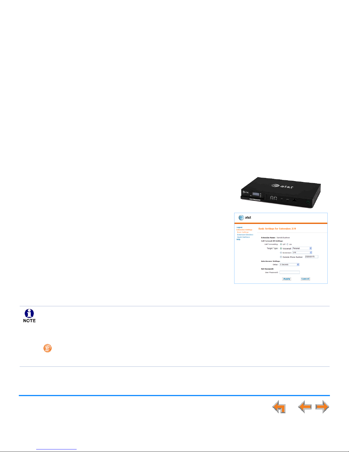
This Installation Guide provides instructions for installing and setting up your Synapse system with software version 1.9.5 or later.
See page 13 for instructions on checking the software version on the Gateway, the Deskset, and the ATA.
Before using this AT&T product, please read “Appendix E: Important Safety Instructions” on page 216. Please read this guide
thoroughly for all the information necessary to install your new AT&T product.
Using This Guide
The following sections provide instructions for using this guide:
“Topic Navigation” on page 7
“Text Conventions” on page 8
“Deskset and Cordless Handset Menu Navigation” on page 9.
For customer service or product information, contact the person who installed your system. If your installer is
unavailable, visit our web site at
www.telephones.att.com/smb
or call
1 (888) 916-2007
. In Canada,
dial
1 (888) 883-2474
.
Some illustrations in this document contain very small text that is not intended to be read. Sometimes the image is
present just to help you find the correct screen; in others, full size text conveys the intended information.
Page 8
Preface 7
Synapse Installation Guide
Topic Navigation
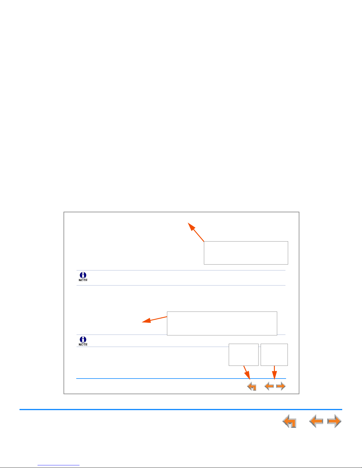
This guide allows easy navigation between topics and the ability to return to your original topic. Figure 1 illustrates the navigation
conventions within the guide.
Figure 1. Installation Guide Navigation
Synapse Installation Guide
Preface 6
P
REFACE
This Installation Guide provides instructions for installing and setting up your Synapse system with software version 1.9.2 or later.
See page 13 for instructions on checking the software version on the Gateway, the Deskset, and the ATA.
Before using this AT&T product, please read Appendix E: Important Safety Instructions on page 205. Please read this guide
thoroughly for all the information necessary to install your new AT&T product.
Using This Guide
The following sections provide instructions for using this guide:
Topic Navigation on page 7
Text Conventions on page 8
Deskset and Cordless Handset Menu Navigation on page 9.
For customer service or product information, contact the person who installed your system. If your installer is
unavailable, visit our web site at
www.telephones.att.com/smb
or call
1 (888) 916-2007
. In Canada,
dial
1 (888) 883-2474
.
Some illustrations in this document contain very small text that is not intended to be read. Sometimes the image is
present just to help you find the correct screen; in others, full size text conveys the intended information.
Task Link
Click on this link to move to the beginning
of the instructions for this task.
Back to Table of Contents
Click on the page heading to
move to the Table of Contents.
Previous
and Next
Page
Back to
Last Page
Viewed
Page 9
Preface 8
Synapse Installation Guide
Text Conventions
Table 1 lists text formats and their uses.
Table 1. Description of Text Conventions
Text Format Description
Screen Identifies text that appears on the screen in a title, menu, or
prompt.
HARD KEY or DIAL-PAD KEY Identifies a hard key, including the dial-pad keys.
Identifies a soft key.
Figure 1, Table 1 Identifies a figure or table.
“Topic Navigation” on page 7 Identifies a hyperlink to another part of this document or, if it
begins with ”www”, an Internet web site. You need Internet
access to view web sites.
[PSTN], [T1], [ATA], [Handset], [Headset] Identifies information predominately about devices and
capabilities beyond the basic configuration of a Gateway and
Desksets. See “System Overview” on page 11.
Example of a Note.
Example of a Caution.
Notes give more information, usually in a
procedure.
A caution means that loss of data or unintended
circumstances may result.
Page 10

Preface 9
Synapse Installation Guide
Deskset and Cordless Handset Menu Navigation
To access items in the menus, you can either use the Navigation key to highlight the function and press SELECT or press a numeric
key on the dial pad. The procedures in this guide use the numeric keypad entry as the preferred method for selecting a function.
Additional Documentation
Downloadable copies of all Synapse documents, including user’s and administrator’s guides, installation instructions and
quick-start guides, are available at
www.telephones.att.com/synapseguides
.
Page 11
Installation 10
Synapse Installation Guide
C
HAPTER
1
I
NSTALLATION
This section describes the physical installation of the Synapse devices. Each system must
include at least one PSTN Gateway or one T1 Gateway. Each PSTN Gateway supports up to
four analog telephone lines. Up to four PSTN Gateways can support up to 16 analog
telephone lines. The T1 Gateway supports up to 23 T1 PRI voice channels.
“System Overview” on page 11
“Planning Your System and Network Configuration” on page 19
“Recommended Installation Sequence” on page 17
“Planning Your System and Network Configuration” on page 19
“Site Preparation” on page 32
“Assigning Telephone Lines and Extensions” on page 35
“Gateway and ATA Placement” on page 37
“Gateway Installation” on page 41
“Deskset Installation” on page 45
“SB67050 ATA Installation” on page 52
“SB67040 Cordless Handset Installation” on page 58
“TL7600 Cordless Headset Installation” on page 61.
You can view Synapse installation videos at
www.telephones.att.com/smb
.
In the left navigation menu, click on Product Support and then Video Gallery.
Page 12
Installation 11
Synapse Installation Guide
System Overview
1. AT&T SB67010 PSTN Gateway — Each PSTN Gateway provides access to up to four
analog outside telephone lines. The system can have up to four PSTN Gateways,
supporting up to 16 telephone lines. Information that is only about the PSTN Gateway is
designated by [PSTN] in this guide.
2. AT&T SB67060 T1 Gateway — The T1 Gateway supports the T1 PRI (Primary Rate
Interface) that provides access to up to 23 voice channels to support up to 23
simultaneous calls. The system can have only one T1 Gateway. Information that is only
about the T1 Gateway is designated by [T1] in this guide.
3. AT&T SB67020 Deskset — A Deskset with a standard screen and Programmable Feature
Keys. The system can have up to 100 Desksets, and you can combine SB67020 and
SB67030 Desksets. Information that is only about the SB67020 Deskset is designated by
[020] in this guide.
4. AT&T SB67030 Deskset — A Deskset with a large screen and a DECT 6.0 radio to host
the optional Cordless Handset and Headset accessories. The system can have up to 100
Desksets, and you can combine SB67030 and SB67020 Desksets. Information that is only
about the SB67030 Deskset is designated by [030] in this guide.
5. AT&T SB67040 Cordless Accessory Handset (Optional, requires SB67030 Deskset) —
The Cordless Handset duplicates many of the Deskset features and provides a high
degree of mobility. Information that is only about the Cordless Handset is designated by
[Handset] in this guide.
6. AT&T TL7600 Cordless Accessory Headset (Optional, requires SB67030 Deskset) — The
Headset lets you work while you talk. Information that is only about the Cordless Headset
is designated by [Headset] in this guide.
1
3
56
2
4
Page 13
Installation 12
Synapse Installation Guide
7. AT&T SB67050 Analog Terminal Adapter (ATA - Optional) — The ATA allows the
integration of non-Synapse devices, such as analog telephones, a fax machine,
overhead paging equipment, and a music-on-hold source into the Synapse system. It
also provides Group Mailboxes to allow different people to access the same Mailbox.
The system can have only one ATA. Information that is only about the ATA is
designated by [ATA] in this guide.
8. Web User Interface (WebUI) — The WebUI provides the ability to customize your
system for your business from a PC that is on the same Local Area Network. The
WebUI resides on the Gateways, ATA, and Desksets, and is updated with device
software updates. See “Updating Devices” on page 135.
You can register only one AT&T SB67040 Cordless Handset and only one AT&T TL7600 Cordless Headset to a SB67030
Deskset. Up to five SB67030 Desksets can have cordless accessories, although this number can increase depending
on your office environment. Factors such as proximity of Desksets, number of simultaneous calls, and structural
obstacles affect how many Desksets can have cordless accessories. When a Deskset has cordless accessories, they are
all part of the same extension, and only one extension device can be used at a time.
To integrate the Headset into the system, see “User Settings” in the SB67030 Deskset and Accessories User’s
Guide at
www.telephones.att.com/synapseguides
, rather than the manual that is packaged with the
Headset.
8
7
Page 14
Installation 13
Synapse Installation Guide
Software Version Compatibility
Systems with software versions 1.9.5 and later support the features described in this
guide. All Gateways, ATAs and Desksets must have compatible software versions
installed.
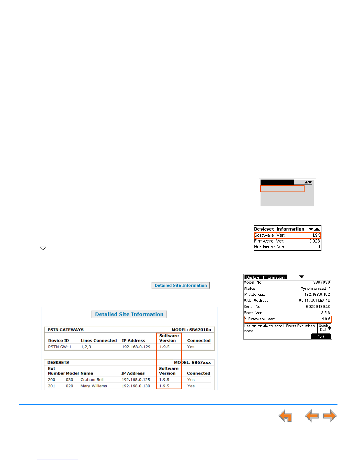
To determine the software version of Gateways and the ATA from the device front
panel, from idle, press SELECT, SELECT, and then DOWN. The software version
appears, as shown in Figure 3.
To determine the SB67020 Deskset software version, press MENU, then 4, and then
the Navigation key to display the software version as shown in Figure 4.
To determine the SB67030 Deskset software version, press MENU, then 4. See the
P Firmware version as shown in Figure 5.
To determine the software version of all installed devices, log in as administrator. See
“Log in as Administrator” on page 91. Then click to see the
software versions and other information, as shown in Figure 2. There may be a delay
as the system gathers this information.
Figure 2. Detailed Site Information
Figure 3. Gateway Software Version
Figure 4. SB67020 Deskset Software
Version
Figure 5. SB67030 Deskset Software
Version
6:9HUY
):9HU=
'HYLFH,QIR
Page 15
Installation 14
Synapse Installation Guide
System Installation Overview
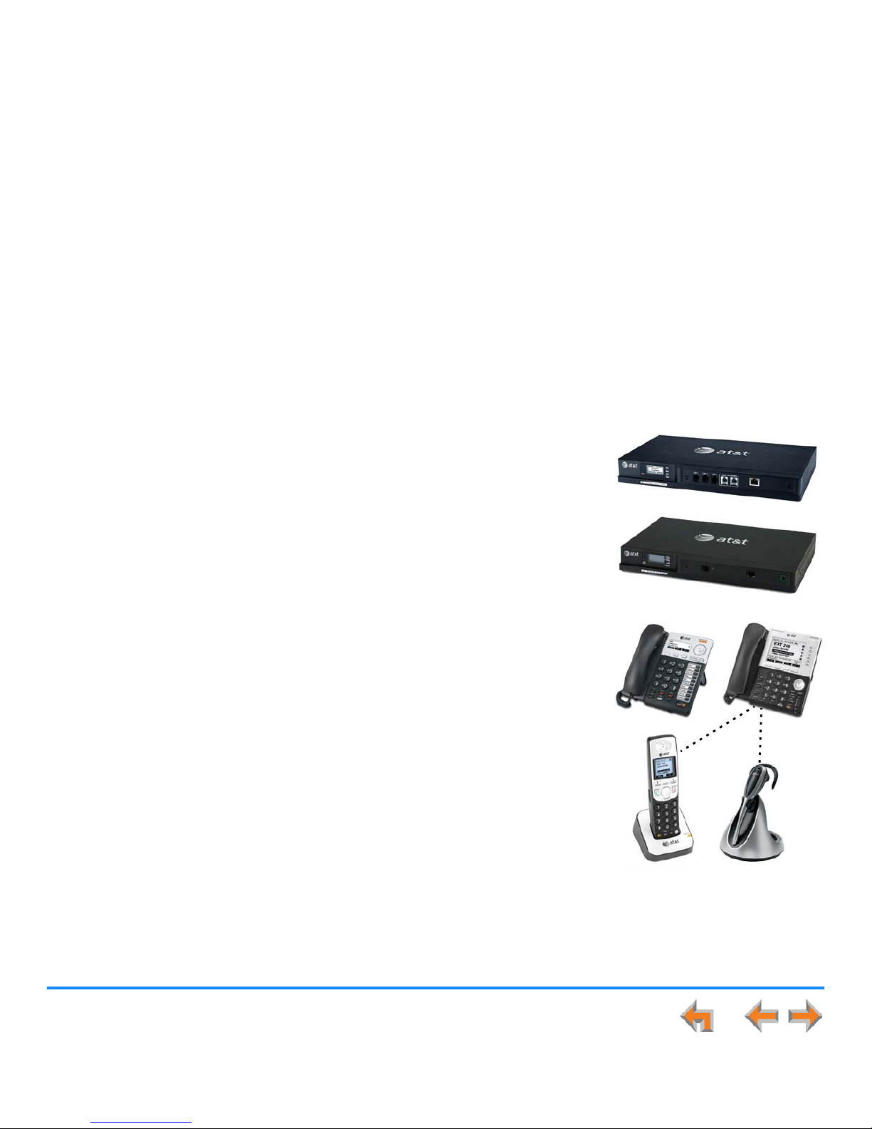
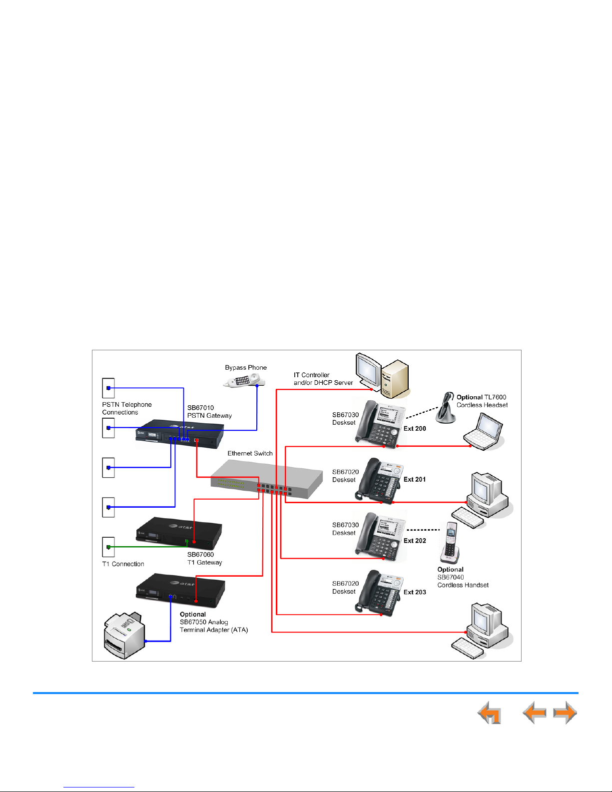
Figure 6 illustrates how the Synapse system differs from conventional telephone systems in that calls are not coordinated by a
central controller. Instead, the system uses a distributed control system over a new or existing LAN.
Figure 6. Sample System Network
Page 16
Installation 15
Synapse Installation Guide
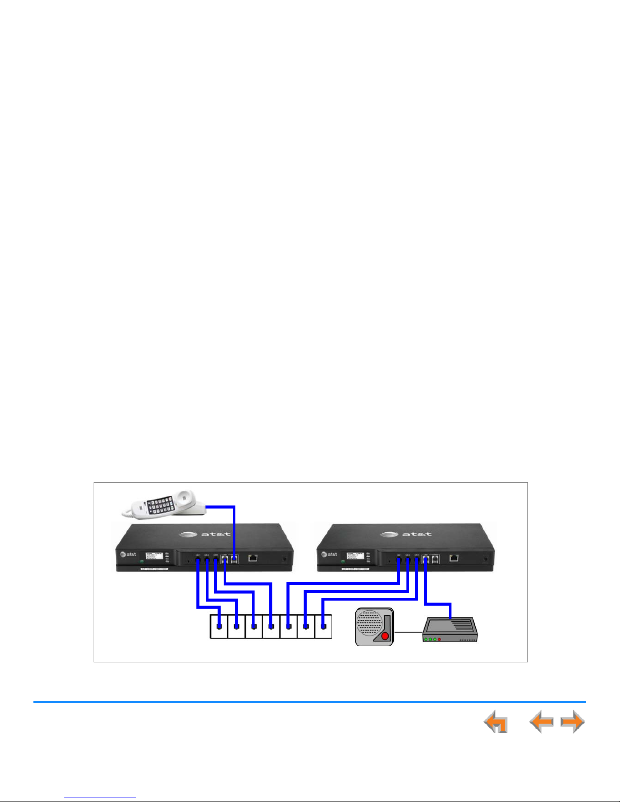
If you install one SB67010 PSTN Gateway or SB67060 T1 Gateway and then one Deskset, the feedback described in this guide
matches what you see on your system devices.
A system must have at least one PSTN Gateway or one T1 Gateway. There can be up to four PSTN Gateways, and a system can
include both a T1 Gateway and PSTN Gateways. Figure 7 illustrates the minimum components needed to make the system work
(blue line = telephone; red lines = Ethernet).
Figure 7. Simplified System (PSTN Gateway and SB67030 Deskset Shown)
The system uses a Local Area Network (LAN) for system communication. It uses Public Switched Telephone Network
(PSTN) connections for outside calls.
Deskset Local Area Network (LAN) Gateway PSTN Plug
Page 17

Installation 16
Synapse Installation Guide
System Installation Overview with Optional Analog Terminal Adapter
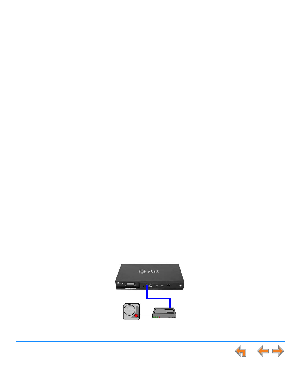
If you have analog devices that you want to attach to the system, you will need an AT&T SB67050 Analog Terminal Adapter (ATA).
The Synapse system supports one ATA per system. The ATA allows you to attach hardware such as conference phones, overhead
paging equipment, a fax machine, or a source for Music On Hold (MoH) to Synapse. Figure 8 illustrates a more complex installation
(blue lines = telephone; red lines = Ethernet; orange lines = audio), but there are different options for attaching some of the
equipment to the ATA.
Install the ATA after you have installed at least one Gateway and the Desksets.
Figure 8. Example of a System Featuring an ATA
Deskset
GatewayLocal Area Network (LAN) PSTN Plug
Music on Hold
Source
Fax Machine
ATA
Analog
Telephone/
Conference
Phone/
Door Phone
Overhead
Paging
System
Page 18

Installation 17
Synapse Installation Guide
Recommended Installation Sequence
1. Prepare your site for installation. See “Site Preparation” on page 32.
2. Install the PSTN and/or T1 Gateways. See “Gateway Installation” on page 41.
3. If you have only one Gateway, install the first Deskset. See “Deskset Installation” on page 45. This Deskset is assigned
extension number 200 with no Direct Inward Dialing.
4. If necessary, change the mode of operation from Call Appearance mode to Line Appearance mode. See “About Modes of
Operation” on page 19.
5. Configure the Dial Plan Settings and [T1] Direct Inward Dialing (DID). Unless you do this, the other Desksets will be assigned
sequential three-digit extension numbers starting with 201 and without DID numbers.
To use DID, see “Dial Plan Settings” on page 96 and “Direct Inward Dial (T1 Gateway)” on page 100.
Use the WebUI to change the Dial Plan Settings if you want the first extension digit to be something other than 2, possibly
to correspond to the DID numbers, or if you want the parked-call extension numbers to start with a digit other than 1.
After changing the Number of Digits and Default Phone Extension Prefix, manually change the extension number of the first
Deskset you installed, and manually set its DID number.
Changing the number of extension digits after installing some Desksets may result in undesired extension number reassignment, where the last three digits of previous extension numbers may not be preserved.
6. Install the other Desksets. See “Deskset Installation” on page 45.
7. Optional: Install the AT&T SB67050 Analog Terminal Adapter (ATA). See “SB67050 ATA Installation” on page 52. If you install
the ATA with phones or a fax machine connected to an FXS port before installing a Deskset, that device will default to being
the operator. Install the ATA after installing at least one Deskset so that a Deskset is the default operator.
You cannot enable Line Appearance mode if a T1 Gateway is installed in your system. Line Appearance mode is not
compatible with the T1 Gateway and T1 Gateway features such as DID.
Page 19

Installation 18
Synapse Installation Guide
8. Connect any analog device such as a fax machine, paging system, or door phone to the ATA. For more information, see:
“Connecting Analog Telephones” on page 53
“Connecting a Fax Machine” on page 54
“Connecting an Overhead Paging System (OHP)” on page 55
“Station Port (FXS) Door Phone Support” on page 27.
9. Configure the system using the WebUI. See “System Configuration” on page 88.
10. Complete post-installation tasks.
If you have set the system to use Call Appearance mode, ask all users to record their user names on their Desksets.
See “Name Recording for the Auto Attendant Directory” in the Synapse Administrator’s Guide at
www.telephones.att.com/synapseguides
.
If you have set the system to use Call Appearance mode, distribute and register any Cordless Handsets or Headsets.
Synapse Cordless Handsets are not compatible with Line Appearance mode. See “SB67040 Cordless Handset Installation”
on page 58 and “TL7600 Cordless Headset Installation” on page 61.
Check for software upgrades and register your Synapse system products. See “Product Registration” on page 140.
Page 20

Installation 19
Synapse Installation Guide
Planning Your System and Network Configuration
This section describes several important configuration options that you should be aware of before you install the Synapse system.
These options include Operation Mode (Call Appearance versus Line Appearance), IP addresses and connectivity, extension
number assignments, analog bypass lines and analog telephones in the Synapse system.
About Modes of Operation
The system administrator can configure the Synapse system to operate in one of two different modes: Call Appearance mode and
Line Appearance mode. The operation mode affects how Deskset users make, answer, and manage calls. Each mode provides a
unique set of configurable features.
Before beginning the installation, you and the system administrator should decide which mode will work best for the site.
Call Appearance Mode
In Call Appearance mode, each Deskset has virtual “lines” (5 on SB67030 Desksets, and up to 10 on SB67020 Desksets) for calls
to and from external numbers (232-555-0176, for example) or other extensions (Extension 220, for example). These virtual lines
are called Call Appearances.
Systems using Call Appearance mode can have any combination of PSTN Gateways, T1 Gateway, and an optional ATA. In Call
Appearance mode, SB67030 Desksets can have SB67040 Cordless Handsets and TL7600 Cordless Headsets.
Line Appearance Mode
In Line Appearance mode, each line that Deskset users can access corresponds to an actual physical line connected to the PSTN
Gateway (the Synapse system can have up to four PSTN Gateways providing up to 16 lines). Incoming lines are mapped to
Programmable Feature Keys on Desksets. You can assign different lines to different Desksets or groups of Desksets. You can
configure SB67020 Desksets to access up to 9 lines and SB67030 Desksets to access up to 4 lines.
Other Desksets in the system can share these lines and display the line status. Incoming calls on a line ring at all Desksets that
share that line. Users at Desksets that share lines can see when lines are ringing, busy, or on hold.
Page 21

Installation 20
Synapse Installation Guide
Systems using Line Appearance mode must use PSTN Gateways only. An optional ATA is also compatible with Line Appearance
mode. For more information, see “ATA Fax Line Configuration” on page 36. A system using Line Appearance mode cannot support
the T1 Gateway, Ring Groups, Call Queue and some Deskset-specific features. For more information, see the Synapse
Administrator’s Guide.
In Line Appearance mode, SB67030 Desksets cannot use SB67040 Cordless Handsets, although TL7600 Cordless Headsets are
compatible with Line Appearance mode.
IP Addresses and Connectivity
An IP address is an individual numeric identification assigned to devices on a computer network. At least one Synapse device
needs a network-assigned IP address on the subnet shared with any computers that will allow access to the WebUI. Valid IP
addresses on the same subnet allow devices on the network to identify each other and enable communication.
This IP address may be assigned from a Dynamic Host Configuration Protocol (DHCP) server, or set statically to the same subnet,
and will be separate from the self-assigned 169.254.xxx.xxx link-local address that the Synapse devices use to communicate with
each other. When setting up the IP address on a Synapse device, this network IP address used for WebUI connectivity is the only
address you can change.
The network IP addresses can be assigned in two ways:
1. The Synapse device can request a network server to automatically assign an IP address. This IP address is a dynamic
assignment; the address is on lease from the server. The lease is renewed as long as the device remains connected and there
is no change to the network. However, if the device is disconnected, or if there is a network or AC power interruption, the
lease may not be renewed (that is, the IP address expires) and a new IP address may be assigned.
Most LANs use servers to automatically assign IP addresses. Synapse defaults to assuming that this automatic assignment
will occur.
Some servers have default settings that limit the number of network IP addresses assigned to devices on the network.
You should log in to your server to confirm that the IP range is sufficient to accommodate at least one of the Synapse
devices that you are adding as at least one Synapse device needs an assigned IP address to enable WebUI
configuration activities. Consult the IT department if you need help checking the server.
Page 22

Installation 21
Synapse Installation Guide
2. The Synapse Administrator can manually assign a static system IP address. This IP address does not change, even when there
are network or AC power interruptions. Some installations will require manual static IP assignment.
A switched-network topology is recommended. This topology refers to the network virtual shape or structure and does not
necessarily reflect the physical layout. Switched networks involve connecting the network components to switches rather than
hubs; this improves network communication.
Extension Assignments
The system assigns the first Deskset to join the network as extension 200. At this point you can use the WebUI to set a different
first digit for extension numbers for Desksets that will be connected to the network. If desired, you should also change the number
of digits from three to four at this point. See “Dial Plan Settings” on page 96.
The system automatically assigns each additional Deskset an extension number in ascending order as it is connected to the LAN.
Once the Desksets are connected to the same network, they find each other through Peer-to-Peer (P2P) discovery protocols and
automatically self-configure. Additional telephony and network configuration is administered through the WebUI.
Even if you unplug a unit, its extension number is reserved. If you want to remove an extension from the network, you must delete
the extension number using the WebUI Device Management menu. Deletion ensures that the Deskset does not tie up an
extension. You can use the WebUI to change or delete extension numbers. For more information, see the Synapse Administrator’s
Guide.
Page 23
Installation 22
Synapse Installation Guide
Overhead Paging Overview
You can set up either single or multi-zone external overhead paging (OHP), as shown in Table 2, but only one OHP system can
be connected to the ATA. Synapse supports most OHP systems that can connect to PBX Analog Station (FXS) ports as well as
those that support direct Audio Input detection, also known as VOX Detect. If you already have an OHP, you need to figure out
the necessary configuration before installation and setup. This introduction may help you figure out your system. If not, refer to
your OHP system's product documentation for installation and configuration instructions or contact your OHP equipment provider.
Table 2. [ATA] Single- vs. Multi-Zone Overhead Paging Systems
Single-Zone Paging Multi-Zone Paging
Broadcasts to all overhead speakers at once. Broadcasts to speakers grouped into separate zones.
Can be included in a Synapse Paging Zone. See “Paging
Zones” on page 125.
Cannot be included in a Synapse Paging Zone because the
multi-zone OHP cannot be paged together with Desksets.
Does not appear in the Deskset Paging Zones menu unless
you add Single-Zone paging to a paging zone you create.
Automatically appears in the Deskset Paging Zones menu as
Overhead Paging.
Requires no additional user input to initiate a page. Requires using the Deskset dial pad to enter digits to address
the OHP paging zone.
For a connection through a FXS port, requires you to set a
delay determined by trial and error. This delay, which starts
after the user presses , gives the paging equipment
time to prepare to broadcast the message. It is required for
every page, even if the OHP is not the chosen paging zone.
See “Single-Zone Overhead Paging Delay” on page 123.
There is no programmed delay as the paging equipment
provides feedback to the user when to start speaking.
Can be connected to an FXS port or the AUX Out jack. Must be connected to the FXS port.
Page 24
Installation 23
Synapse Installation Guide
If your OHP is single-zone, you will have to decide whether it requires an FXS connection or an AUX OUT connection. You can
only connect a multi-zone OHP to an ATA FXS port, i.e. a multi-zone OHP system cannot be connected to the AUX OUT port.
Equipment that can interface with the AUX OUT jack can be “dumb” in its audio output. It doesn't require any exchange of signals
to be ready to broadcast.
Equipment that uses an FXS port must be able to go on and off hook, because the FXS ports use telephone signals to exchange
information. The OHP generally includes some sort of controller or telephone interface, which often requires setting up, for
example, “PABX loop start trunk port access”, or “RJ-11 for Tip and Ring connections”.
There are three possible OHP configurations.
Single-Zone Paging
Single-zone paging means that all speakers connected to the OHP system are activated together (i.e they are in the same zone).
Single-Zone OHP equipment connected to the AUX
OUT jack:
Use this configuration to connect single-zone paging
equipment that uses a 3.5 mm audio jack as input. For
example, use this configuration if the OHP device is
just an amplified speaker. Verify that the OHP input
levels are compatible with ATA level. See “Appendix A:
Technical Specifications” on page 201. Only single-
zone paging is supported in this configuration.
Even though the OHP has no RJ-11 jack, it may still have a Tip/Ring interface, requiring hard wiring. Whenever possible,
try both the AUX OUT jack and an FXS port to find the best configuration for your needs.
Figure 9. Single-Zone Overhead Paging on AUX OUT Jack
Page 25
Installation 24
Synapse Installation Guide
Single-Zone OHP equipment connected to one of
the FXS ports:
Use this configuration to connect paging equipment
that interfaces through a telephone line. Typically, any
OHP that connects to an FXS port has some intelligence
to go off and on hook or otherwise send a signal back
to the pager. These are generally controllers or
telephone interfaces with controls and settings.
In this configuration, you can specify a paging delay to
compensate for the fixed delay introduced by the OHP
system. This delay ensures that the paging tone is played simultaneously on both Desksets and on the OHP system. See “Single-
Zone Overhead Paging Delay” on page 123.
Figure 10. Single-Zone Overhead Paging on FXS Port
Page 26
Installation 25
Synapse Installation Guide
Multi-Zone Paging
Broadcasts to speakers grouped into separate zones. Since the multi-zone OHP systems require zone selection, they cannot be
combined into one zone together with Synapse Desksets.
Multi-Zone OHP equipment connected to one of the FXS ports:
When paging is configured as a multi-zone OHP, a dedicated Overhead Paging zone automatically appears as the last entry in
the Deskset paging menu.
Overhead paging cannot be added to Synapse-specific paging zones (see “Multi-Zone Overhead Paging” on page 124)
because the multi-zone OHP cannot be paged together with Desksets.
Figure 11. Multiple-Zone Overhead Paging on FXS Port
Page 27

Installation 26
Synapse Installation Guide
Verified Overhead Paging Devices
Table 3 lists OHP systems that have been demonstrated to work with the Synapse System as of the publication of this document.
More OHP systems may also have qualified for this list. For more information, call
1 (888) 916-2007
. In Canada,
dial
1 (888) 883-2474
.
The OHP system may have settings that need to be adjusted to work with Synapse. Refer to your OHP system’s product
documentation for installation and configuration instructions.
See “ATA Features” on page 74 for more information on making connections to the ATA.
Desksets and single-zone OHPs can be included in the same zone. In the case of a single-zone OHP connected to the
FXS port, this Paging System and the Desksets generate different paging tones. Note that users hear both tones at the
same time if the paging delay is set properly in the WebUI settings.
Table 3. [ATA] Verified Overhead Paging Devices
Single Zone Multi Zone
Aux Out Jack
Bogen TPU35B
Valcom 1030c
FXS Port
Bogen TAMB
Bogen TPU15A
Bogen TPU35B (alternate to TPU15A)
Viking CPA-7B
Valcom V-9940
Valcom V-9941A
FXS Port
Bogen PCM 2000
Bogen PCM TAMB
Bogen TPU15A or TPU35B
Bogen ZPM3
Page 28
Installation 27
Synapse Installation Guide
Door Phones Overview
Door phones and their associated door-entry mechanisms have become a common accessory in business phone systems. Door
phone systems provide an easy method for Deskset users to attend to someone who is present at a door elsewhere. Synapse
supports two types of door phones: Station Port (FXS) and Trunk Port (FXO). The system lets you select which Desksets will be
notified by the door phone.
A Deskset user can send DTMF digits from the Deskset to the door phone to activate associated door-latch and relay mechanisms.
How the door phone operates using a Deskset and the method to control a door latch varies with the door phone model.
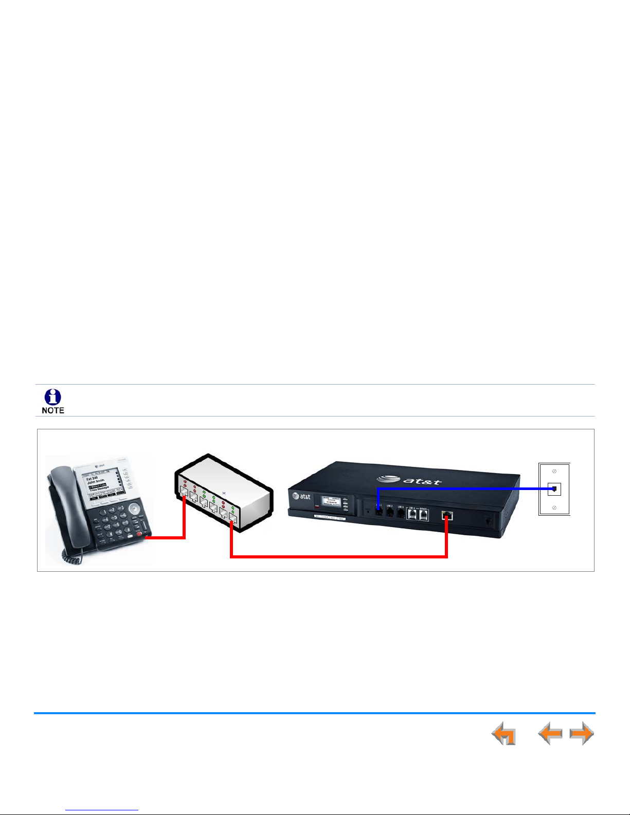
Station Port (FXS) Door Phone Support
This type of door phone emulates a regular analog phone and can be connected to either FXS1 or FXS2 of a Synapse SB67050
ATA as shown in Figure 12. For single-button door phones a feature called Private Line Automatic Ring-down (PLAR) is supported.
With PLAR configured in Synapse, as soon as the phone goes off-hook it will cause the configured extension(s) to ring with a preset Caller ID. Any Synapse extension can call the associated extension of the ATA port connected to the Doorphone.
In Call Appearance mode, you can configure PLAR to ring either a single extension or group of extensions (a Ring Group) when
the door phone goes off hook. In Line Appearance mode, you can configure PLAR to ring a single extension. For more information,
see “ATA FXS Ports” on page 116.
Figure 12. Station Port (FXS) Door Phone Connection
ATA FXS 1 & FXS 2
FXS Door Phone
Page 29
Installation 28
Synapse Installation Guide
Trunk Port (FXO) Door Phone Support
A Trunk Port (FXO) door phone can be connected to any one of the four Line (FXO) ports on a Synapse SB67010 PSTN Gateway
as shown in Figure 13. The FXO door phone can be configured to call either a single extension or a group of extensions (a Ring
Group). You can use the WebUI to configure an FXO door phone. For more information, see “Configuring a Trunk Port (FXO) Door
Phone” on page 128.
In Call Appearance mode, Synapse requires a dedicated door phone line to be Trunk Reserved to a spare Deskset in order for
other Desksets not to seize that line for outbound calls. If there are no extra Desksets available for Trunk Reservation, the door
phone should be connected to the last, or closest to last, line of the last Gateway to limit the chance of the door phone line
being seized.
In Line Appearance mode, the Deskset user must be aware not to use the assigned line key for regular outbound telephone calls.
Desksets automatically select a line when going off-hook, so the Deskset will seize an assigned door phone line if all other lines
are busy.
Figure 13. Trunk Port (FXO) Door Phone Connection
FXO Door Phone
Bypass Phone
PSTN Gateway #1
FXO Lines 1–4
PSTN Gateway #2
FXO Lines 5–8
PSTN Telephone Connections
Page 30

Installation 29
Synapse Installation Guide
Tested Door Phone Models
Table 4 lists door phones that have been demonstrated to work with the Synapse System as of the publication of this document.
More door phones may also have qualified for this list. For more information, call
1 (888) 916-2007
. In Canada,
dial
1 (888) 883-2474
.
Table 4. Verified Door Phones
Trunk Port (FXO) Door Phones Station Port (FXS) Door Phones
ALGO 3226 Trunk Port Door Phone (with 3201 Digital
Door Station)
Valcom V-2900 Trunk Port Door Phone
Valcom V-2901 Trunk Port Door Phone
ALGO 3008 Station Port Door Phone (with 3106 Door
Control Module)
Page 31

Installation 30
Synapse Installation Guide
Connecting Analog Devices to the ATA
The ATA allows you to attach the following analog devices to the ports and jacks identified in Figure 37 on page 52. Most options
require the system administrator to configure the feature in the WebUI. See “The Web User Interface (WebUI)” on page 89 for
information on configuring and using third-party devices. If you are planning to install more than one type of analog equipment,
make sure there are suitable ATA ports available and configured.
Analog telephones, including conference phones
If not used for a fax machine or for Overhead Paging, the two FXS station ports on the ATA allow for connecting standard
POTS (Plain Old Telephone Service) analog telephones and conference phones. When an ATA is added to the Synapse
system, the FXS ports are automatically assigned extension numbers that can be changed by the system administrator
using the WebUI. Users can make and receive calls on those analog telephones, but system features such as Hold, Call
Forward, and Transfer are not supported. You can use the WebUI to assign features such as Ring Group, Auto Attendant
menus, and Call Forward–No Answer targets to an analog telephone.
An analog telephone connected to an FXS port can be used for Private Line Automatic Ringdown (PLAR). When you enable
the PLAR feature through the WebUI, an analog telephone or device connected to an ATA FXS port will ring a destination
when it goes off hook. To configure a PLAR destination, see “ATA Settings” on page 115.
A single fax machine to share your general telephone lines instead of using a dedicated fax line
One of the two FXS station ports can be configured to support a fax machine. The system administrator must configure
the Fax mode in the WebUI.
Overhead Paging Equipment (OHP)
See “Overhead Paging Overview” on page 22. The ATA provides three options to connect OHP. The system administrator
must configure the OHP in the WebUI.
Single-zone paging with OHP equipment connected to the ATA Aux Out jack
Single-zone paging with OHP equipment connected to one of the FXS station ports
Multi-zone paging with OHP equipment connected to one of the FXS station ports.
Page 32

Installation 31
Synapse Installation Guide
Loud Ringers
Loud Ringer devices must be connected to an FXS port assigned as Voice (default setting). Loud Ringers can be used for
alerting users of an incoming call via a loud speaker and are treated within Synapse as a regular analog phone instead
of OHP equipment. This type of overhead alerting can only be done by including the voice FXS port in a Ring Group.
A source for Music On Hold (MoH)
You can use the ATA to route MoH audio input to outside held, parked, or queued calls. When external callers are placed
on hold, parked, or enter a call queue, they hear the audio source provided by the MoH input. The system administrator
must configure the MoH in the WebUI. See “Hold Settings and Music on Hold (Requires ATA)” in the Synapse
Administrator’s Guide.
Door phone
See “Station Port (FXS) Door Phone Support” on page 27.
Page 33

Installation 32
Synapse Installation Guide
Site Preparation
This section describes how to prepare your site for a successful Synapse system installation.
Network Requirements
For more information on the network configuration, see “Planning Your System and Network Configuration” on page 19.
A switched network topology is recommended for your LAN (using standard 10/100 Ethernet switches that carry traffic
at a nominal rate of 100 Mbit/s).
The office LAN infrastructure should use Cat.-5 (or better) cable.
The LAN connections to Synapse devices should all be wired. However, wireless connections to other devices (such as
laptops) in your office network that are not part of the Synapse system will not impede performance.
All devices in the Synapse system must reside on a single subnet.
A DHCP server is recommended and must be on the same subnet as the Synapse system so that IP addresses can be
auto-assigned. If no DHCP server is present, you can assign static IPs if desired. DHCP or static IPs are only required if
the system is to be managed from an external network. Synapse devices will self-assign link-local IP addresses for all
voice communication in addition to any DHCP or static IPs that are assigned for management purposes.
Unless you want to manually set the Synapse clock and upgrade Synapse software, an Internet connection to the LAN is
required.
A DNS server is recommended to resolve the path to the Internet and to the AT&T server for software upgrades.
If a routing path to the Internet is not available, the system administrator can download the upgrade files and use the
WebUI to upgrade the software manually.
For users whose computers require a GigE Ethernet frame rate (a gigabit per second), use separate Ethernet connections
for the Deskset and the computer. The Ethernet connection through a Deskset is limited to 100 Mbits/s.
Page 34

Installation 33
Synapse Installation Guide
Placement Considerations
Avoid placing any Synapse component too close to the following:
Communication devices, such as television sets, DVD players, or other cordless telephones
Excessive heat sources
Noise sources, such as a window with traffic outside, motors, microwave ovens, refrigerators, or fluorescent lighting
Excessive dust sources, such as a workshop or garage
Excessive moisture
Extremely low temperature
Mechanical vibration or shock, such as on top of the washing machine or workbench.
ATA Placement Considerations
You can install the optional ATA near the Gateway, or near one of the third-party devices that are being used with it. For example,
it might be easier to connect the ATA to the fax machine in the room with the fax machine instead of running a telephone line
connection from the fax to an ATA located in a telephone equipment cabinet.
Power Considerations
Ensure that there is an electrical outlet not controlled by a wall switch within 6 feet (1.83 m) of each device location.
SB67020 Desksets are also compatible with Power over Ethernet (PoE). To use PoE, your network needs a switch that provides
PoE. Using PoE simplifies your installation by eliminating the need to route separate power cords. It also allows you to protect
your system from power outages by connecting an Uninterruptible Power Supply (UPS) to your PoE switch, Gateways, and ATA.
Ensure that the PoE switch output power is set to Class 2.
Page 35

Installation 34
Synapse Installation Guide
Other Preparations
Before installing the Gateway and Desksets, the following preparations may need to be taken:
All PSTN lines must be gathered into one access point situated no more than 9 feet (2.74 m) from the Gateway location.
If rewiring is required, contact your telephone service provider and request the help of a qualified technician.
You may need one or more network switches set up to ensure there are sufficient ports available for other devices in the
network (such as a DSL modem).
If you plan to use the emergency bypass feature on the PSTN Gateway, you will need an analog phone.
An Ethernet Port must be available within 9 feet (2.74 m) from each Deskset location. Each Deskset is capable of sharing
an Ethernet port with a PC. If one Ethernet port already exists at a workstation, another port is not necessary unless you
need a GigE Ethernet frame rate. Use a separate Ethernet connection for the Deskset and the computer.
Page 36

Installation 35
Synapse Installation Guide
Assigning Telephone Lines and Extensions
This section discusses various telephone line configuration issues to consider.
Providing Limited Telephone Service During AC Power Outages
PSTN Gateway
The fourth line on each PSTN Gateway is a Bypass port that works during AC power failures. If you have a PSTN line plugged into
LINE 4, connect a line-powered analog telephone to the RJ-11 jack labeled BYPASS for telephone service during power failures.
When power returns, a relay disconnects this emergency bypass line so that the bypass line cannot be used to eavesdrop on
normal calls.
If your telephone lines are part of a hunt group (a telephone company feature that allows calls to a busy phone number to roll
over to the next available telephone line), connect the line with your main (pilot) telephone number to PSTN Gateway LINE 4.
If your system features both PSTN Gateways and a T1 Gateway, outbound calls are placed first through the T1 channels.
T1 Gateway
The T1 Gateway provides no analog bypass port. To provide telephone communication during power outages, either subscribe to
at least one analog phone line and install a PSTN Gateway or use uninterruptible power supplies to provide power to your
computer network, the Synapse T1 Gateway, and one or more system Desksets.
Analog Line Connection Order on PSTN Gateways
For outgoing calls, the system first seizes the lowest idle PSTN port numbers (as labeled on the PSTN Gateway). PSTN phone lines
should be connected to your system with your busiest incoming line placed in the highest port number on the highest numbered
PSTN Gateway, so that incoming calls are less likely to receive busy signals. For instance, if your customer service team receives
many calls, you would want to plug their phone lines into higher-numbered PSTN ports.
Page 37

Installation 36
Synapse Installation Guide
ATA Fax Line Configuration
To support fax on the Synapse system, you should consider where the fax is, and which telephone line will be used for incoming
faxes. Fax line configuration for the Synapse system differs depending on whether you are using a PSTN Gateway or a T1 Gateway.
PSTN Gateway
The PSTN fax line can be connected to any FXO port (LINE 1–4) on the PSTN Gateway. However, trunks for outgoing calls are
seized in ascending order (LINE 1 then LINE 2, and so on). To avoid using the fax line for outgoing voice calls, make the fax line
the highest possible numbered line on the highest numbered Gateway. Use the Fax Configuration page in the WebUI to select
a telephone line on the PSTN Gateway as the fax line. See “Fax Configuration” on page 119.
If your office has heavy fax volume, the fax line should be a separate dedicated line, and not part of a hunt group.
If your office has low fax volume, your telephone service provider may be able to include your fax line in the hunt group. This
way, you can save on the expense of a separate fax line. In this scenario, you can maximize your system for voice usage while
maintaining the capacity to send or receive the occasional fax.
You should consider the following issues when fax and voice calls share a PSTN Gateway line:
Incoming calls that get routed through the PSTN Gateway fax line are automatically checked by the system for a fax
signal. Voice callers will experience a delay of up to eight seconds before the call is connected to the Auto Attendant or
Operator.
For outgoing calls, the caller ID of the fax number may be sent instead of the primary business telephone number. If the
recipient returns a missed call via their caller ID log, the caller will then experience the eight-second delay mentioned
above.
T1 Gateway
When a T1 Gateway is installed, you can assign a DID number for the fax machine on the Fax Configuration WebUI page. See
“Fax Configuration” on page 119. Incoming faxes are routed directly to that DID number (with no eight-second delay), and
outgoing faxes are sent with the DID number as their caller ID.
Page 38

Installation 37
Synapse Installation Guide
Gateway and ATA Placement
You can place the Gateway or ATA on a tabletop, mount it into a standard 19-inch metal rack, or wall mount it. The PSTN Gateway
must be installed within three feet of the building ground point. Install each device using the following instructions.
Rack Mounting
To mount the Gateway or ATA into a standard 19-inch rack:
Figure 14. Rack-mount Bracket
Figure 15. Bracket Installed
1. Remove the two mounting brackets and six screws from the packing tissue.
2. Position a bracket at the front of the device, as shown in Figure 14.
3. To align the screw holes, place the bracket on the device so that the locating
indent on the bracket matches the indent on the device.
4. Insert each of the three screws into the holes provided and tighten securely as
shown in Figure 15. Repeat the process for the other bracket.
5. Position the chassis into the 19-inch metal
rack, as shown in Figure 16..
6. Insert a top mounting screw (not included)
in one side and turn it several turns to
establish support. Repeat for the other
side.
7. Tighten the screws.
Locating Indent
Figure 16. Rack Installation
Page 39

Installation 38
Synapse Installation Guide
Wall Mounting
To mount the Gateway or ATA to a wall:
Figure 17. Gateway Wall
Mounting
You can mount the Gateway or ATA to a wall using the two mounting slots on the bottom of
the device. Ensure that the device is oriented as shown in Figure 17 to allow air to flow
vertically through the ventilation holes on each side of the device.
1. Install two pan-head screws (with ¼-inch diameter head) 7 ⅞ inches (20 cm) apart. The
screw shaft diameter should be ⅛-inch (3.2 mm). Ensure you use anchors appropriate for
your mounting surface. Leave about ⅛-inch (3.2 mm) clearance between the screw head
and the wall.
2. Position the device with the mounting slot centers aligned over the mounting screws.
Carefully bring the device down onto the screws.
3. Slide the device downwards so that the screws go into the mounting slots on the device.
Ensure the device is secure.
Page 40

Installation 39
Synapse Installation Guide
Grounding
The SB67010 PSTN Gateway, the SB67060 T1 Gateway, and the SB67050 Analog Terminal Adapter must be connected to reliable
earth ground. The connection to earth ground must be verified by qualified personnel.
The SB67010 PSTN Gateway must be connected to reliable earth ground using the supplied ground wire connected to a terminal
on the back of the Gateway chassis.
The SB67060 T1 Gateway must be connected to reliable earth ground through a separate ground wire connected to a terminal
on the back of the Gateway chassis before connecting the T1 cable.
The SB67050 Analog Terminal Adapter is connected to earth ground through a properly grounded wall outlet. Additional
grounding may be necessary for the ATA if you need to improve immunity to Electrostatic Discharge (ESD) and to minimize the
possibility of electrical interference when using third-party audio equipment.
To provide additional grounding, the ATA can be connected to reliable earth ground through a separate ground wire connected
to a terminal on the back of the ATA chassis.
Page 41

Installation 40
Synapse Installation Guide
To ground the Gateway or ATA:
1. Acquire a grounding cable of 18 AWG or greater gauge. For the PSTN Gateway, use the supplied grounding cable.
2. Locate the device near the building ground point, usually located at the electrical breaker box. The PSTN Gateway must
be within three feet (91.4 centimeters) of the building ground point.
3. Loosen the grounding terminal screw on the back of the device, as identified in Figure 18 and Figure 19.
4. Insert the end of the grounding cable under the grounding terminal.
5. Tighten the screw.
6. Connect the other end of the grounding cable to the building ground point, usually located at the electrical breaker box.
Figure 18. PSTN Gateway Grounding
Figure 19. T1 Gateway and ATA Grounding
If you are unsure about the location of the building ground point or how to ground the device, contact the facilities
manager.
Grounding Terminal
Grounding Terminal
Page 42

Installation 41
Synapse Installation Guide
Gateway Installation
To install the Gateway:
1. Install a Gateway first. Plug the AC plug into an electrical outlet not controlled by a wall switch and the DC plug into the
DC jack, as shown in Figure 20. Wait up to one minute until the screen lights up.
2. Plug a grey Cat.-5 LAN cable for the PSTN Gateway or yellow Cat.-6 LAN cable for the T1 Gateway into the Ethernet port
marked LAN. Use the supplied cables or a comparable substitute. Plug the other end of the cable into your office LAN. The
T1 Gateway is Gigabit Ethernet (GigE) capable, so it has a Cat.-6 LAN cable. The Desksets and other devices require only
Cat.-5 cables.
.
Figure 20. Gateway Power and LAN Connections
LAN DC Power
T1 Gateway
PSTN Gateway
Page 43

Installation 42
Synapse Installation Guide
To install the Gateway: (Continued)
Figure 21. Synchronized
The Gateway takes about a minute to power up.
After another Synapse device is installed, and after the Gateway has found the network
and the other Synapse device, Synchronized appears on the third line of the display, as
shown in Figure 21. This is the Idle screen.
The time and date may not be correct. You can set the time and date on the System Basic
Settings page in the WebUI or using the Deskset Admin Settings menu. For more
information, see the Synapse Administrator’s Guide.
PSTN Gateway
T1 Gateway
Page 44

Installation 43
Synapse Installation Guide
To connect the PSTN Gateway telephone lines:
1. Remove the plastic covers from the Gateway PSTN (telephone) jacks to be used, marked LINE 1 through LINE 4 and
BYPASS, as shown in Figure 22.
Figure 22. PSTN Gateway Telephone Line Connections
2. Plug up to four telephone lines from the telephone wall jacks into the Gateway. The line
LEDs blink for up to 15 seconds during initialization.
DC 5.1V
LINE 1
LINE 2 LINE 3 LINE 4 BYPASS
LAN
RESET
LINE 1
LINE 2
LINE 3
LINE 4
POWER
SELECT CANCEL
DOWN
UP
+-
LINE 1
through
LINE 4
BYPASS
Telephone Line LEDs
If your service provider uses Centrex lines, you must use the WebUI to enter a line access code to allow calibration
to take place. Before connecting the PSTN lines, see “Line Calibration Configuration” on page 134.
Figure 23. DSL Connection
If you subscribe to Digital Subscriber Line (DSL) high-speed Internet service
through your telephone line, you must plug each telephone line with DSL service
into a DSL filter. Then plug the DSL filter into the telephone wall jack, as identified
in Figure 23.
For customer service or product information, contact the installer at the number on the cover of this guide. If your
installer is unavailable, visit our website at
www.telephones.att.com/smb
or call
1 (888) 916-2007
. In
Canada dial
1 (888) 883-2474
.
Page 45

Installation 44
Synapse Installation Guide
[
To connect the T1 Gateway T1 cable:
Plug the black T1 cable into the Gateway T1 Port, as shown in Figure 24, and into your T1/PRI network device from your service
provider.
Do not make any calls until the POWER and the SYN/ACT LEDs are green. See “T1 Gateway Features” on page 67.
Figure 24. T1 Gateway Line Connections
The SB67060 T1 Gateway must use only No.26 AWG or larger Telecommunications line cord to reduce the risk of
fire.
For customer service or product information, visit our website at
www.telephones.att.com/smb
or call
1 (888) 916-2007
. In Canada dial
1 (888) 883-2474
.
T1 Port
T1 Status Indicators
Page 46

Installation 45
Synapse Installation Guide
Deskset Installation
Figure 25 identifies the features on the bottom and side of the Deskset. You can install the Deskset on a desktop or mount it on
a wall. Figure 25 represents the SB67030 Deskset. Although the SB67020 is slightly different, its features have the same basic
layout.
Figure 25. Deskset Connections
1. Network Port The two LEDs next to each network port indicate
network status and AC power status.
The green LED is on when the Deskset is connected to the
network and has AC power.
The yellow LED flashes when there is network activity.
2. PC Port
3. Reset Button
4. Power Jack The 020 Deskset also supports Power Over Ethernet.
5. Corded Headset Jack (Actual jack location may be different than
shown)
6. Corded Handset Jack
7. Wall-Mount Slots See “To install the Deskset on a wall:” on
page 50.
1 2
3
4
5
6
7
Page 47

Installation 46
Synapse Installation Guide
To attach the Desktop Stand for desktop installation:
Figure 26. Deskset Stand Options
Figure 27. Deskset Stand Installation
1. Select a Deskset position. The desktop setup requires the Deskset
Stand and provides two positions, Option 1 at 45° and Option 2 at
60°, as shown in Figure 26. If you use Option 2, rotate the Handset
tab as explained in “To rotate the Handset tab for wall and Deskset
Option 2 installation:” on page 47
2. Place the Deskset on a flat surface with the power and network ports
facing you, as illustrated in Figure 27.
3. Place the stand, illustrated
in Figure 28, on the base
with the flexible tab side
away from you.
4. Insert the solid tabs of the
stand into the Option 1 or
Option 2 slots on the base
that are marked in red in
Figure 27.
5. Rotate the stand away from you until it rests against the base and
you hear a click as the flexible tabs lock into place.
Option 1 Option 2
Option 1
Option 2
Flexible tabs
Flexible tabs
Solid tabs
Solid tabs
Figure 28. Deskset Stand Tabs
Flexible Tabs
Page 48

Installation 47
Synapse Installation Guide
To rotate the Handset tab for wall and Deskset Option 2 installation:
Figure 29. Handset Tab
1. Press the switch hook and slide the Handset Tab toward the top of
the base, as shown in Figure 29.
2. Rotate the Handset Tab 180°, as shown in Figure 30, so that the
“hook” is at the top.
3. Slide the Handset Tab back into the base, as shown in Figure 31.
Figure 31. Replace Handset Tab
Handset Tab
Switch hook
Figure 30. Handset Tab Rotation
“Hook”
Page 49

Installation 48
Synapse Installation Guide
To connect the Cat.-5 LAN cable to the Deskset:
With a PC:
If there is a networked computer and no extra Ethernet wall jacks near the
Deskset, then plug the PC Ethernet cable into the Deskset so the Deskset and
PC share the same network connection.
1. Unplug the Cat.-5 Ethernet cable from your computer.
2. Plug that Cat.-5 Ethernet cable into the Network port on the back of the
Deskset, as indicated in Figure 32.
3. Plug another Cat.-5 Ethernet cable into the PC port on the Deskset.
4. Plug the other end of the second Cat.-5 Ethernet cable into your computer.
If a GigE network is being used, a computer connected through the
Deskset will be limited to 100 Mbits/s. If you require a GigE Ethernet rate, use separate Ethernet connections for the
Deskset and the computer so that the computer can take advantage of the greater bandwidth.
If a PC is connected to your LAN through a Deskset, any Deskset resets and power or network interruptions will disrupt
the PC’s connection to the network.
Network PC
Figure 32. Network Connections
The PC port on the Deskset is intended for connection to an end-user PC only.
Do not use the PC port to connect to a PC with a heavy bandwidth load (such as a network server PC or a
hub, switch, or router).
Do not use the PC port to extend the network. The end-user PC should be the final point. Do not use the PC
port to connect to other system devices.
Page 50

Installation 49
Synapse Installation Guide
To connect the Cat.-5 Ethernet cable to the Deskset: (Continued)
Without a PC:
If the Deskset has a dedicated network connection, then connect the Deskset to the network connection only.
1. Plug a Cat.-5 Ethernet cable into the Network port on the back of the Deskset, as indicated in Figure 32 on page 48.
2. Plug the other end into the Ethernet wall jack.
To connect power:
Figure 33. Power Connector
[020] If you are using PoE, connecting the Deskset to the network also
connects the power.
If you are using the supplied power adapter:
1. Plug the power adapter (blue tag) into the DC Power jack on the
back of the Deskset, as identified in Figure 33.
2. Plug the power adapter into an outlet not controlled by a wall
switch. The display screen illuminates within about a minute.
If the user's computer is plugged into an uninterruptible power
supply (UPS), consider plugging the Deskset into it, too.
Power Jack
Page 51

Installation 50
Synapse Installation Guide
To install the Deskset on a wall:
Figure 34. Deskset Wall Mount
1. Plug the Ethernet cable into the port on the back of the deskset. (See
“To connect the Cat.-5 LAN cable to the Deskset:” on page 48.)
2. Plug the power adapter into the jack on the back of the deskset. Skip
this step if using POE. (See “To connect power:” on page 49.)
3. Place the Deskset base over the mounting plate above the mounting
studs as shown in .
4. Slide the Deskset base down as shown in .
5. Plug the Ethernet cable into the wall jack.
6. Plug the power adapter into a power outlet not controlled by a wall
switch. Skip this step if using PoE.
7. Make sure the Handset Tab is in Wall position, as described in “To
rotate the Handset tab for wall and Deskset Option 2 installation:”
on page 47.
8. Connect the corded handset to the handset jack on the left side of
the telephone.
Wall-
Mount
Screws
Page 52

Installation 51
Synapse Installation Guide
To connect the corded handset and an optional corded headset:
Figure 35. Handset Cord Connection
Figure 36. Install Optional Headset
Connect the corded handset:
1. Plug the coiled end of the handset cord into the handset jack on
the left side of the telephone, as identified in Figure 35.
2. Plug the end of the handset cord with the longer straight portion
into the handset, then hang up.
Connect an optional corded headset:
Plug an optional corded headset or cordless headset base into the
RJ-9 connector on the bottom of the Deskset, as indicated in
Figure 36.
[030] A headset plugged into this jack takes precedence over a
registered AT&T TL7600 Cordless Headset.
Handset Jack on Handset
Handset Jack
On Deskset
Optional Headset Jack
Do not plug a headset into the jack for the corded handset.
Page 53

Installation 52
Synapse Installation Guide
SB67050 ATA Installation
To install the ATA:
1. After installing at least one Deskset, plug the AC plug into an electrical outlet not controlled by a wall switch and the DC
plug into the DC jack, as shown in Figure 37. Wait up to one minute until the screen lights up.
2. Plug a Cat.-5 Ethernet cable into the port marked LAN. Plug the other end of the Ethernet cable into your office LAN.
Figure 37. ATA Power, LAN, and Station Port Connections
The ATA takes about a minute to power up.
After the ATA has found the network and the Gateway, Synchronized appears on the
third line of the display, as shown in Figure 38. This is the Idle screen.
The time and date may not be correct. The time and date are set using the WebUI. See
“System Settings” on page 94.
3. Remove the plastic covers from the FXS station ports that you are using, as shown in
Figure 37.
To prevent the loss of ATA-supported services during power outages, plug the AC power plug into an
Uninterruptible Power Supply (UPS).
LAN
DC Power
FXS 2
FXS 1
Station Ports
AUX IN AUX OUT
Figure 38. ATA Synchronized
Page 54

Installation 53
Synapse Installation Guide
Connecting Analog Telephones
To install analog telephones:
1. Remove the plastic covers from the FXS 1 and FXS 2 (telephone) ports to be used on the ATA.
2. Plug up to two telephone lines from analog telephones into the ATA FXS 1 and FXS 2 ports, as shown in Figure 39.
Figure 39. ATA Analog Telephone Installation
ATA
Analog Telephone/
Conference Phone
Analog Telephone/
Conference Phone
Page 55

Installation 54
Synapse Installation Guide
Connecting a Fax Machine
To install a fax machine:
1. Remove the plastic covers from the FXS 1 or FXS 2 (telephone) port to be used on the ATA.
2. Plug a telephone line from the fax machine into the ATA FXS 1 or FXS 2 port, as shown in Figure 40.
3. Configure the fax connection in the WebUI.
See ““Fax Settings” on page 120” for information on configuring the ATA to work with your fax machine.
Figure 40. ATA Fax Machine Installation
Fax Machine
ATA
If you are connecting your fax machine to the ATA and your Synapse system uses a trunk prefix, such as 9, you should
inform users that they need to dial the trunk prefix when sending faxes.
Page 56

Installation 55
Synapse Installation Guide
Connecting an Overhead Paging System (OHP)
A Single Zone or Multi-Zone system can be integrated into an existing Synapse network. The control unit or analog amplifier for
the Overhead Paging system connects directly to the ATA via an FXS or the AUX OUT jack, depending on the type of paging
system. Synapse supports most OHP systems that support PBX station ports or auxiliary audio-out connections to a PBX. Some
settings for the OHP may have to be changed to work with Synapse. The following OHP systems have been verified to work with
Synapse.
If you don't know whether your OHP is Single Zone or Multi Zone, see “Overhead Paging Overview” on page 22“. There
are so many types of paging equipment that you may need to contract with a communications equipment professional to
install the OHP.
Single Zone Multi-Zone
Aux Out Jack
Bogen TPU35B
FXS Port
Bogen TAMB
Bogen TPU15A
Bogen TPU35B (alternate to TPU15A)
Valcom 1030c
Viking CPA-7B
Valcom V-9940 (expandable for multi-zone)
Valcom V-9941A (with talkback)
FXS Port
Bogen PCM 2000
Bogen PCM TAMB
Bogen TPU15A or TPU35B
Bogen ZPM3
Whether you are replacing a phone system and using an existing (already working) OHP, or installing a new OHP, the
paging system may have settings that need to be adjusted to work with Synapse.
OHPs that are “Line Mode” that cannot be set to “Station Mode” cannot be used with Synapse.
If you want to connect a single-zone paging system to the AUX OUT jack, you may need to buy or make a custom cable.
Page 57

Installation 56
Synapse Installation Guide
To install an overhead paging system:
1. Remove the plastic cover from the FXS 1 or FXS 2 port to be used on the ATA.
2. Plug the telephone line from the OHP device into the FXS 1 or FXS 2 port, or plug an audio cable from the OHP device
into the Synapse AUX OUT jack, as shown in Figure 41, depending on the requirements of the paging system.
3. Enable the OHP device in the WebUI.
See the “The Web User Interface (WebUI)” on page 89 for information on configuring an OHP device.
Figure 41. ATA Overhead Paging System Installation
Overhead
Paging
System
ATA
Audio Cable Connection
FXS Connection
Page 58

Installation 57
Synapse Installation Guide
Connecting a Music on Hold Source
To install a music on hold source:
1. Use the supplied Auxiliary Audio Cable to plug a streaming audio source, such as a radio or MP3 music player, into the
ATA AUX IN jack as shown in Figure 42. If the supplied cable does not connect to your music source, use another cable
that will connect your device to the 3.5 mm AUX IN jack. This audio source must have a volume control. The volume
adjustment on the audio device should be set to obtain the preferred level of music on hold within the system.
2. Enable Music on Hold in the WebUI.
See “The Web User Interface (WebUI)” on page 89 for information on configuring an OHP device.
Figure 42. ATA Music on Hold Source Installation
The ATA AUX IN jack is set up to receive headset-out audio signals. Do not connect to a “Line-Out” audio source or
to speaker outputs.
On-hold music functionality should only be used in conjunction with music specifically licensed for on-hold use.
Licensed on-hold music is available from many third-party suppliers. AT&T disclaims any liability arising from the failure
to obtain such a license.
Music on Hold
Source
ATA
Page 59

Installation 58
Synapse Installation Guide
SB67040 Cordless Handset Installation
Charger Installation
Place the Handset in the charger when not in use.
To plug the Handset charger into AC power:
Figure 43. Handset Charger Power Connect
1. Plug the power adapter into an electrical outlet not controlled by a
wall switch.
2. Plug the small end of the power adapter into the jack on the
underside of the charger.
3. Route the cord through the slot, as shown in Figure 43.
The SB67040 Cordless Handset requires registration to an SB67030 Deskset. The SB67020 Deskset does not support the
SB67040 Cordless Handset.
The SB67040 Cordless Handset is not supported when the system is in Line Appearance mode.
Page 60

Installation 59
Synapse Installation Guide
Battery Installation
The Handset uses a rechargeable 2.4v nickel-metal hydride cell (NiMH) battery pack.
To install the Handset battery:
Figure 44. Install Handset Battery
1. Remove the battery cover by pressing and sliding the cover downward, as
shown in Figure 44.
2. Plug the battery connector securely into the plug inside the Handset
battery compartment, matching the color-coded label.
3. Place the battery in the compartment with THIS SIDE UP facing up.
4. Align the cover flat against the battery compartment, then slide it upward
until it clicks into place.
If the battery has enough charge, within 10 seconds the LCD displays the
Place in charger screen shown in Figure 45. If there is no charge, the
screen remains blank.
5. Place the Handset in the charger.
Figure 45. Place in Charger
Color-Coded
Battery Connector
Use only the supplied rechargeable battery or replace it with battery
model BT8001. To obtain a replacement battery, visit our website at
www.telephones.att.com/smb
or call
1 (888) 916-2007
.
In Canada, dial
1 (888) 883-2474
.
12:00a Jan. 0012:00a Jan. 00
Place in charger.
Page 61

Installation 60
Synapse Installation Guide
Battery Charging
Charge the Handset battery for at least 16 hours before use. When fully charged, the Handset battery provides approximately
five hours of talk time or three days of standby time.
To charge the Handset battery:
Figure 46. Handset in Charger
Place the Handset in the charger, as shown in
Figure 46.
The CHARGE light is on when the
Handset is charging.
If the Handset has not yet been
registered, the Register screen shown
in Figure 47 appears within 15
seconds.
See the “Handset Registration” section in the AT&T SB67040
Cordless Accessory Handset Quick Start Guide that was
packaged with the Handset and available at
www.telephones.att.com/synapseguides
.
CHARGE light
12:00a Jan. 0012:00a Jan. 00
To register Handset:
1. Go to your
Deskset.
2. Press MENU.
3. Select User
REGISTER
1/3
Figure 47. Register Screen
Place the Handset in the charger when not in use.
Page 62

Installation 61
Synapse Installation Guide
TL7600 Cordless Headset Installation
Charger Installation
The TL7600 cordless headset requires registration to an SB67030 Deskset. The SB67020 does not support the TL7600
cordless headset.
To install the TL7600 charger:
Figure 48. Charger Installation
1. Plug the small end of the charger power adapter into the jack on the underside
of the charger, then route the cord through the slot as shown in Figure 48.
2. Plug the large end of the charger power adapter into an AC wall outlet not
controlled by a wall switch.
Power Jack
Page 63

Installation 62
Synapse Installation Guide
Battery Installation
Install the battery as shown below. For optimal performance, charge the Headset battery for at least six hours before use. When
not in use, recharge the Headset by returning it to the Headset charger.
To install a battery:
Figure 49. Remove Battery Door
Figure 50. Insert Battery and Plug
1. If the battery door is attached, press
on both sides of the battery
compartment cover and lift the cover
up and off as shown in Figure 49.
2. Insert the battery into the battery
compartment with the label THIS
SIDE UP facing up as shown in
Figure 50.
3. Push the battery plug into the
connector inside the compartment
according to the color-coded label and place the wires neatly inside the
compartment as shown in Figure 50.
4. Insert the tab on the bottom of the battery cover into the battery compartment.
Press down gently on the battery cover until it snaps into place as shown in
Figure 51.
Insert Battery
Insert Plug
Figure 51. Replace Battery Door
Remove the ear hook from the Headset before battery replacement.
Use only the supplied rechargeable battery or replace it with battery
model BT191545. To obtain a replacement battery, visit our website at
www.telephones.att.com/smb
or call
1 (888) 916-2007
. In
Canada, dial
1 (888) 883-2474
.
Page 64

Installation 63
Synapse Installation Guide
Battery Charging
After installing the battery, charge the Headset by placing it in the Headset charger as shown below. Before registration, the
Headset ON/OFF
light flashes twice every five seconds whether the Headset is charging or not. After registration, the Headset
ON/OFF light is on when the Headset is charging.
To charge the battery:
Figure 52. Insert Headset
1. Insert the Headset into the charger as shown in Figure 52.
2. Push the Headset downward until the ON/OFF
light on the Headset turns on as shown in
Figure 53.
If the Headset has not yet been registered, the
ON/OFF light flashes blue and orange.
To register the headset, use the process
described in “Registering an Optional
Cordless Headset” in the AT&T SB67030
Deskset and Accessories User’s Guide at
www.telephones.att.com/
synapseguides
.
Figure 53. Headset ON/OFF Light
ON/OFF
Light
Place the Headset in the charger when not in use.
Page 65

Synapse Installation Guide
Getting Started 64
C
HAPTER
2
G
ETTING STARTED
This chapter gets you started with configuring the Synapse system from the devices. Most of
these functions are duplicated in the easier-to-use WebUI described in the next chapter, but
if you need to assign static IP addresses, they must be set at each device. You can only
directly reset a device from the device, although some functions in the WebUI include device
resets.
This chapter covers:
“PSTN Gateway Features” on page 65
“T1 Gateway Features” on page 67
“Gateway Front Panel Interface” on page 69
“Deskset IP Settings” on page 82
“Upgrade Deskset Software” on page 86
“ATA Features” on page 74.
30)(%
3671/LQHV
6\QFKURQL]HG
,3
Page 66

Getting Started 65
Synapse Installation Guide
PSTN Gateway Features
Figure 54 illustrates the PSTN Gateway features and connections.
Figure 54. PSTN Gateway Features and Connections
1. Display Provides system and network status, device information, and configuration data. See
“Gateway Front Panel Interface” on page 69.
2. Reset When pressed momentarily, restarts the Gateway.
When pressed and held for more than five seconds and with the LAN cable not connected,
restores factory defaults.
3. PSTN Line Ports 1–4 Traditional 2-conductor wiring (FXO—Foreign Exchange Office Ports).
4. Bypass Port Traditional analog POTS (Plain Old Telephone Service) that is available during an AC power
outage. When the Gateway power fails, calls on Line 4 are routed to the bypass line.
5. RJ-45 Ethernet Network Port 10Base-T/100Base-Tx with Auto MDI/MDI-X switching.
6. DC 5.1V Power-Supply Jack
DC 5.1V
LINE 1
LINE 2 LINE 3 LINE 4 BYPASS
LAN
RESET
LINE 1
LINE 2
LINE 3
LINE 4
POWER
SELECT CANCEL
DOWN
UP
+-
1
2
3
4 5 6
Page 67

Getting Started 66
Synapse Installation Guide
Figure 55 provides an illustration and description of the PSTN Gateway front panel.
Figure 55. PSTN Gateway Front Panel Description
Key Used To: LED Description
Navigate through the menus, and to
increase/decrease editable fields.
Highlight the previous or next item in the list,
respectively.
Line-status LEDs indicate the status for each
PSTN line. Indications include:
Off – Connected.
Red (steady) – Disconnected.
Green (steady) – In use.
Green (flashing) – Ringing.
Line-status LEDs flash red after lines are
connected (while matching line impedance).
-
Display the Main menu when in idle mode or
while in network detection mode; save
current setting and return to previous menu.
Terminate current operation without saving
new settings and to return to the previous
menu.
Off – No power to the device.
Green – Power is present.
Power LED
Line-Status LEDs
Menu Navigation Keys
Page 68

Getting Started 67
Synapse Installation Guide
T1 Gateway Features
Figure 56 illustrates the T1 Gateway features and connections.
Figure 56. T1 Gateway Features and Connections
1. Display Provides system and network status, device information, and configuration data. See
“Gateway Front Panel Interface” on page 69.
2. Reset When pressed momentarily, restarts the Gateway.
When pressed and held for more than five seconds and with the LAN cable not connected,
restores factory defaults.
3. T1 Port
4. RJ-45 Ethernet Network Port 10Base-T/100Base-Tx with Auto MDI/MDI-X switching.
5. DC 12V Power-Supply Jack
1
2 3 4 5
Page 69

Getting Started 68
Synapse Installation Guide
Figure 57 provides an illustration and description of the T1 Gateway front panel.
.
Figure 57. T1 Gateway Front Panel Description
Key Used To: LED Description
Navigate through the menus, and to increase/
decrease editable fields.
Highlight the previous or next item in the list,
respectively.
Off – T1 is not synchronized with T1 network.
Green – T1 Synchronization.
Green (flashing) – Active call.
Display the Main menu when in idle mode or
while in network detection mode; Save current
setting and return to previous menu.
Off – No RAI/LOF/LOS errors.
Yellow – Remote Alarm Indication (RAI).
Red (steady) – Loss Of Frame (LOF).
Red (flashing) – Loss Of Signal (LOS).
Terminate current operation without saving
new settings and to return to the previous
menu.
Off – No Alarm Indication Signal.
Blue – Alarm Indication Signal.
Off – No power to the device.
Green – Power is present.
Off – Network not in local loopback mode.
Green (steady) – Network Loopback.
Green (flashing) – Payload Loopback.
Red – T1 Gateway is not synchronized with
the LAN.
Power LED
Status LEDs
Menu Navigation Keys
Page 70

Getting Started 69
Synapse Installation Guide
Gateway Front Panel Interface
You can access basic information and perform some configuration tasks using the Gateway’s front panel. Most of these tasks are
easier to do using the WebUI. See “The Web User Interface (WebUI)” on page 89.
The Gateway displays the Idle screen upon completion of the power-up sequence. Use the Gateway Main menu to perform some
system operations.
Figure 58. Gateway Idle
Screens
To access the Gateway Main menu from the Idle screen, as shown in Figure 58,
press the key. The menu provides the following functions:
Device Information
Network Status
Configuration
30)(%
3671/LQHV
6\QFKURQL]HG
,3
30)HE
6\QFKURQL]HG
,3
7*:
PSTN Gateway
T1 Gateway
Page 71

Getting Started 70
Synapse Installation Guide
Figure 59. Gateway Menu
Screens
Press the key to highlight an entry, as shown in Figure 59, then press
to see information about your Gateway or your Network. Select
Configuration to view or modify some Gateway settings. Here is the information
you can see in Device Information and Network Status:
Device Information
Model #
Serial #
Boot Version
Software Version
Firmware Version
Network Status
IP Address
Subnet Mask
Default Gateway
DNS Server X
MAC Address
Network Port
Local Address
The T1 Gateway does not display
its firmware version.
Page 72

Getting Started 71
Synapse Installation Guide
Gateway Configuration
Figure 60. Gateway
Configuration
Press / in the Gateway Main menu until Configuration is highlighted, as
shown in Figure 60, and press to display the Configuration menu. The current setting
is indicated with . You can use this interface or the WebUI to upgrade software. Here are
the configuration settings:
Configuration — Current Gateway settings.
Auto IP — Is set automatically.
Static IP — You can change the static IP only from the Gateway. Although the Gateway
prompts you through the process, using a static IP address can have serious effects;
contact your installer if static IP address editing is required.
Restore Defaults — Highlight Restore Defaults and press and hold for two
seconds when prompted to restore the Gateway to factory defaults.
Upgrade Software — Highlight Upgrade Software and press . If new software
is available, you are prompted to press again to accept the upgrade.
Page 73

Getting Started 72
Synapse Installation Guide
Upgrade Gateway Software
If you have system settings that you want to retain, back up the settings before upgrading the system software.
To upgrade the Gateway software to the latest version:
Figure 61. Upgrade
Software
1. Press / in the Gateway Main menu until Configuration is highlighted and
press to display the Configuration menu, as shown in Figure 61.
2. Press to highlight Upgrade Software and press to initiate the software
upgrade process. The device initiates a link to the Synapse Software Updates web site host
and any new software.
If a host cannot be found or the server name cannot be resolved, Timeout or Host
Not Found appears. Upgrade the software from the PC, which can offer more
information about connection issues. See “To manually update a device to the latest
software version:” on page 138.
If the host is found, but there is no new software available, then the No New Version
message appears.
If the device is sluggish or unresponsive during the upgrade process, see “A Synapse
device becomes sluggish or unresponsive during or immediately after software
upgrade.” on page 171.
Page 74

Getting Started 73
Synapse Installation Guide
To upgrade the Gateway software to the latest version: (Continued)
Figure 62. Downloading
Software
3. If new software is available, you are prompted to initiate the upgrade by pressing ,
or abort by pressing .
Once the downloading starts, the display indicates the progress as shown by the
percentage indicator, as shown in Figure 62.
If the upgrade process is interrupted by removing the server connection, no restart
occurs. The Gateway remains on the xx% complete screen, until an action is taken at
that Gateway. The process does not resume even after the server connection is
reestablished.
Pressing during the programming process terminates the download midstream
and returns you to the Configuration menu. The previous software version remains in
effect.
When the upgrade is complete, the screen briefly displays 100% complete, then 0%
complete for few seconds, before restarting the Gateway.
4. Press repeatedly until you return to the Gateway Main menu.
Page 75

Getting Started 74
Synapse Installation Guide
ATA Features
When the ATA is first connected to your LAN, the two FXS ports are configured as POTS phone lines and assigned the next
available extension numbers. ATA extension numbers do not appear in the Extension list on Deskset screens. They do, however,
appear on Call Logs, Redial lists, and Message lists. The two ATA extensions do not count toward the 100-extension limit of the
Synapse system.
Configure the interface to these analog devices through the WebUI. See “ATA Settings” on page 115.
In addition, one 10/100BT Ethernet port is provided for communication with the Synapse network. The front panel LCD and
buttons allow network configuration, firmware upgrades, and information functions. Figure 63 illustrates the ATA features and
connections.
Figure 63. ATA Features and Connections
1. Display Provides system and network status, device information, and configuration data.
2. Reset When pressed momentarily, restarts the ATA. When pressed and held for more than five
seconds and with the LAN cable not connected, restores factory defaults.
3. FXS 1, FXS 2 Station jacks for analog telephones, a fax machine, door phone, or overhead paging
equipment.
4. AUX IN Audio in for MoH.
5. AUX OUT Audio out, an option for OHP.
6. RJ-45 Ethernet Network Port 10Base-T/100Base-Tx with Auto MDI/MDI-X switching.
7. DC 12V Power-Supply Jack
1
2 3 4 5 6 7
Page 76

Getting Started 75
Synapse Installation Guide
Figure 64 provides an illustration and description of the ATA front panel.
Figure 64. ATA Front Panel Description
Key Used To: LED Description
Navigate through the menus, and to
increase/decrease editable fields.
Highlight the previous or next item in the list,
respectively.
Station jack status LEDs indicate:
Off – No connection detected or idle
Green (steady) – Line activity detected
Green (flashing) – Ringing
Display the Main menu when in idle mode or
while in network detection mode.
Save current setting and return to previous
menu.
Audio status LEDs indicate:
Off – Not configured in the WebUI
Red (steady) – Configured in the WebUI, but
no connection detected.
Green (steady) – Configured and connected.
Green (flashing) – Paging active.
Terminate current operation without saving
new settings and to return to the previous
menu.
Off – No power to the device.
Green – When power is present.
Power LED
Status LEDs
Menu Navigation Keys
Page 77

Getting Started 76
Synapse Installation Guide
ATA Front Panel Interface
You can access basic information and perform some configuration tasks using the ATA front panel. These tasks are easier to do
using the WebUI. See “The Web User Interface (WebUI)” on page 89.
The ATA displays the Idle menu after powering up. Access the ATA Main menu to perform the system operation functions. The
Idle screen is different, but the menus are the same as that of the PSTN Gateway.
Figure 65. ATA Idle Screen
Figure 66. ATA Menu Screens
To access the ATA Main menu from the Idle screen, as shown in Figure 65, press the
key. The menu provides the following functions:
Device Information
Network Status
Configuration
Press the key to highlight an entry, then press to see information about
your ATA or your network, as shown in Figure 66. Select Configuration to view or
modify some ATA settings. Here is the information you can see in Device Information and
Network Status:
Device Information
Model #
Serial #
Boot Version
Software Version
Firmware Version
Network Status
IP Address
Subnet Mask
Default Gateway
DNS Server X
MAC Address
Network Port
Local Address
30)HE
6\QFKURQL]HG
,3
$7$
Dev ic e Inf or mation
Netw ork Status
Conf iguration
Netw ork Status
IP A ddress: (DHCP)
192.168.0.100
Page 78

Getting Started 77
Synapse Installation Guide
ATA Configuration
Figure 67. ATA
Configuration
Press / in the ATA Main menu until Configuration is highlighted, as shown in
Figure 67, and press to display the Configuration menu. The current setting is
indicated with . You can use this interface or the WebUI to upgrade software. Here are the
configuration settings:
Configuration — Current ATA settings:
Auto IP — Is set automatically.
Static IP — You can change the Static IP only from the ATA. Although the ATA prompts
you through the process, using a static IP address can have serious effects; contact
your installer if Static IP editing is required.
Restore Defaults — Highlight Restore Defaults and press and hold for two
seconds when prompted to restore the ATA to factory defaults.
Upgrade Software — Highlight Upgrade Software, and press . If new software
is available, you are prompted to press again to accept the upgrade.
Page 79

Getting Started 78
Synapse Installation Guide
Upgrade ATA Software
If you have system settings that you want to retain, back up the settings before upgrading the system software.
To upgrade the ATA software to the latest version:
Figure 68. Upgrade
Software
1. Press / in the ATA Main menu until Configuration is highlighted and press
to display the Configuration menu, as shown in Figure 68.
2. Press to highlight Upgrade Software and press to initiate the software
upgrade process. The device initiates a link to the Synapse software updates web site host
and any new software.
If a host cannot be found or the server name cannot be resolved, Timeout or Host
Not Found appears. Upgrade the software from the PC, which can offer more
information about connection issues. See “To manually update a device to the latest
software version:” on page 138.
If the host is found, but there is no new software available, then the No New Version
message appears.
If the device is sluggish or unresponsive during the upgrade process, see “A Synapse
device becomes sluggish or unresponsive during or immediately after software
upgrade.” on page 171.
Page 80

Getting Started 79
Synapse Installation Guide
To upgrade the ATA software to the latest version: (Continued)
Figure 69. Downloading
Software
3. If new software is available, you are prompted to initiate the upgrade by pressing ,
or abort by pressing .
Once the downloading starts, the display indicates the progress as shown by the
percentage indicator, as shown in Figure 69. The device restarts automatically once
the programming is completed.
If the programming process is interrupted by removing the server connection, no
restart occurs. The process does not resume even after the server connection is
reestablished. The ATA remains on the xx% complete screen until an action is taken
at the ATA.
Pressing during the programming process terminates the download and
returns you to the Configuration menu. The previous software version remains in
effect.
When the upgrade is complete, the screen briefly displays 100% complete, then 0%
complete for few seconds, before restarting the ATA.
4. Press repeatedly until you return to the ATA Main menu.
Page 81

Getting Started 80
Synapse Installation Guide
Resetting Devices
You may need to manually restart a device or return a device to factory defaults (see “Appendix B: Default Settings” on page 204).
To reset a device, press the RESET button shown in Figure 70 and Figure 71 by inserting a pen or paper clip into the hole and
applying pressure to the button. The T1 Gateway and ATA (not shown) have a RESET button in the same location on the front
panel as the PSTN Gateway. Although Figure 71 on page 81 shows the SB67030 Deskset, the SB67020 Deskset reset button is
in the same location.
To restart the device without losing any custom settings, press the RESET button for less than five seconds. You can get the same
result by disconnecting and reconnecting power to the device. You can restart the device if the device does not respond or fails
to synchronize with the system.
To completely reset the device to factory defaults, unplug the LAN cable and press the RESET button for more than five seconds.
You might do this if the device is not synchronized or you want to reset the IP address settings to Auto (DHCP). Any static IP
configurations are lost.
When resetting a Deskset to factory defaults, the system configuration (the user settings and Personal directory) and Voicemail
messages, Call Log, and the Redial list are all deleted. You can use this complete reset when assigning Desksets to new users. If
you do not disconnect the LAN cable before pressing the RESET button, the extension number is retained. During the reset, any
PC connected to the Deskset PC port momentarily loses network connectivity.
If there is one Gateway in the system, but there are still Desksets connected, then only the voice prompts and hold messages
are deleted; the rest of the Auto Attendant settings are maintained on the Desksets. If there is another Gateway, the other
Gateway maintains all system configuration settings.
To reset the entire system to factory defaults and completely clear the system of all settings (Auto Attendant, Ring
Groups, hold message, and System Directory) and Voicemail messages, unplug the LAN cables from all devices and press
the RESET button for more than five seconds on each device. Then reconnect all devices to the LAN.
If you have already set up the system, back up the Deskset and system settings before resetting the device to factory
defaults. For more information, see the Synapse Administrator’s Guide.
Page 82

Getting Started 81
Synapse Installation Guide
n
Figure 70. PSTN Gateway Reset Button
Figure 71. Deskset Reset Button
DC 5.1V
LINE 1
LINE 2 LINE 3 LINE 4 BYPASS
LAN
RESET
LINE 1
LINE 2
LINE 3
LINE 4
POWER
SELECT CANCEL
DOWN
UP
+-
Reset Button
LAN Port
Reset Button
Page 83

Getting Started 82
Synapse Installation Guide
Deskset IP Settings
Synapse system devices are connected to a LAN so they can communicate with each other. See “System Installation Overview”
on page 14 for a discussion of the Synapse network configuration and IP settings.
To display the IP Settings screen:
Figure 72. 030 IP Settings
1. Access the Admin Settings menu: Press MENU,
then press 3 on the dial pad, then enter the
Admin password (12345 is the default password),
and press SELECT.
2. Press 3 on the dial pad to display the IP Settings
screen shown in Figure 72 and Figure 73.
3. Perform one of the following:
a. Press 1 to select IP Configuration. See “To
set the IP Configuration:” on page 83.
b. Press 2 to select Set/Edit Static IP. See “To
set and edit static IP Address:” on page 84.
c. Press 3 to select IP Status. See “To view the
IP status:” on page 85.
Figure 73. 020 IP Settings
Quick
Dial
2. Set/Edit Static IP
Save
IP Se ttings
3. IP Status
1. IP Configuration Auto
Use or to move highlight.
Us e or to c y c le through options .
IP Settings
1. IP Configur ation
2. Set/Edit Static IP
3. IP Status
Page 84

Getting Started 83
Synapse Installation Guide
To set the IP Configuration:
Figure 74. 030 IP Configuration -
Static
Figure 75. 030 IP Configuration -
Auto
1. Access the Admin Settings menu: Press MENU,
then press 3 on the dial pad, then enter the
Admin password, and press SELECT.
2. Press 3 on the dial pad to display the IP Settings
menu shown in Figure 74 and Figure 76.
3. On the 020 Deskset, press 1 to select
IP Configuration.
The screen shown in Figure 75 or Figure 77
appears.
4. Press the or Navigation key to select
or , as shown in Figure 75 and Figure 78.
5. Press to accept the changes and return
to the Admin Settings menu.
Figure 76. 020 IP Settings
Figure 77. 020 IP
Configuration - Static
Figure 78. 020 IP
Configuration - Auto
Quick
Dial
2. Set/Edit Static IP
Save
IP Se ttings
3. IP Status
1. IP Configuration Static
Use or to move highlight.
Us e or to c y c le through options .
Quick
Dial
2. Set/Edit Static IP
Save
IP Se ttings
3. IP Status
1. IP Configuration Auto
Use or to move highlight.
Us e or to c y c le through options .
IP Settings
1. IP Configur ation
2. Set/Edit Static IP
3. IP Status
IP Configur ation
Set IP to: Stat ic
Save
IP Configur ation
Set IP to: Auto
Save
Page 85

Getting Started 84
Synapse Installation Guide
Set/Edit Static IP
If your business requires a static IP address, contact your network administrator.
To set and edit static IP Address:
Figure 79. 030 IP Settings
Figure 80. 030 Set/Edit Static IP
1. Access the Admin Settings menu: Press MENU,
then press 3 on the dial pad, then enter the
Admin password, and press SELECT.
2. Press 3 on the dial pad to display the IP Settings
screen shown in Figure 79 and Figure 81.
3. Press 2 to display the screen shown in Figure 80
or Figure 82.
4. Enter digits:
There is a 12-digit limit on the number field
(not including dots).
On the 030, pressing the pound key (#)
inserts a dot. On the 020, pressing
inserts a dot.
Pressing when the cursor is
positioned next to a dot deletes the dot and
the digit to the left of the dot.
5. Press the or Navigation key to cycle
through the four fields.
6. Press to accept the changes and return
to the Admin Settings menu.
Figure 81. 020 IP Settings
Figure 82. 020 Set/Edit
Static IP
Quick
Dial
2. Set/Edit Static IP
Save
IP Se ttings
3. IP Status
1. IP Configuration Auto
Use or to move highlight.
Us e or to c y c le through options .
Quick
Dial
Save
Static IP Edit
IP Address:
Subnet Mask:
Gate way:
DNS Se rve r :
Backspc
Us e dial pad to ent er digits and pres s #
to enter a dot.
IP Settings
1. IP Configur ation
2. Set/Edit Static IP
3. IP Status
Set/Edit Static IP
IP Address:
Sub net M ask :
Save Backspc"."
Page 86

Getting Started 85
Synapse Installation Guide
IP Status
This screen is for informational purposes only.
To view the IP status:
Figure 83. 030 IP Settings
Figure 84. 030 IP Status
1. Access the Admin Settings menu: Press MENU,
then press 3 on the dial pad, then enter the
Admin password, and press SELECT.
2. Press 3 on the dial pad to display the IP Settings
screen shown in Figure 83 and Figure 85.
3. Press 3 to display the IP Status screen shown in
Figure 84 and Figure 86.
4. Press the or Navigation key to view status
entries that are not shown on-screen, such as
those shown in Figure 87 and Figure 88.
5. Press to return to the Admin Settings
menu.
Figure 85. 020 IP Settings
Figure 86. 020 IP Status 1
Figure 87. 020 IP Status 2
Figure 88. 020 IP Status 3
Quick
Dial
2. Set/Edit Static IP
Save
IP Se ttings
3. IP Status
1. IP Configuration Auto
Use or to move highlight.
Us e or to c y c le through options .
Quick
Dial
Ex it
IP Status
IP Type:
IP Address:
Subnet Mask:
Gatew ay:
MAC Address:
Ne t w o r k Po r t :
PC Port:
DNS S e rv e r 1:
Auto
192.168.0.123
255.255.255.0
192.168.0.1
00:11:A0:00:12:8D
Connected
Connected
192.168.0.134
Use or to scroll. Press
Ex it
when
done.
The list is not circular, so when you reach the
end of the available text, pressing the
Navigation key has no effect. If you are at the
top of the screen, pressing the Navigation
key has no effect.
IP Settings
1. IP Configur ation
2. Set/Edit Static IP
3. IP Status
IP Status
IP Type :
IP Address:
Sub net M ask :
Auto
192.168.0.123
255.255.255.0
IP Status
Gatew ay: 192.168.0.1
MAC Add: 00:11:A0:00:12:8D
Network Port: Connected
IP Status
Ne t w o r k Po r t:
PC Port:
DNS Ser ve r 1 192.168.1.1
Conne cte d
Conne cte d
Page 87

Getting Started 86
Synapse Installation Guide
Upgrade Deskset Software
To access the Deskset Software Upgrade feature:
Figure 89. 030 Software Upgrade
Figure 90. 030 Upgrade Available
1. Access the Admin Settings menu: Press MENU,
then press 3 on the dial pad, then enter the
Admin password, and press SELECT.
2. Press 5 to display the screen shown in Figure 89
or Figure 91. The system scans for an upgrade.
If an upgrade is available, the screen shown in
Figure 90 or Figure 92 appears. Press
[030] or [020] to return to
the Admin Settings menu.
If no upgrade is available, the screen shown
in Figure 94 on page 87 or Figure 93 appears.
Figure 91. 020 Software
Upgrade
Figure 92. 020 Upgrade
Available
Figure 93. 020 No New
Version
4XLFN
'LDO
([ L W
Software Upgrade
&XUUHQW,PDJH9HUVLRQ
V\QDSVHGVSHWUDY LPJ
Scanning for Upgrades...
4XLFN
'LDO
([ L W
Software Upgrade
3UHVV
8SJUDGH
WR XSJUDGHI LUPZDUH
6\ V WHP ZLOOUHERRW
&XUUHQW,PDJH9HUVLRQ
V\QDSVHGVSHWUDY LPJ
$YDLODEOH,PDJH9 HUVLRQ
V\QDSVHGVSHWUDY LPJ
Found New Version
8SJ U DG H
6RIWZDUH8SJUDGH
6
FDQQLQJIRU
XSJU
DGH V
V\ QDSVHGVY LPJ
6RIWZDUH8SJUDGH
)R
XQG1HZ 9H UV LRQ
V\ QDSVHGVY LPJ
8SJUDGH &DQ F HO
6RIWZDUH8SJUDGH
1R
1HZ9HUVLRQ
V\ QDSVHGVY LP J
([ L W
Page 88

Getting Started 87
Synapse Installation Guide
To access the Deskset Software Upgrade feature: (Continued)
Figure 94. 030 No New Version
Figure 95. 030 Upgrading
3. Press to install the upgrade. The screen
shown in Figure 95 or Figure 96 appears.
The Deskset automatically resets at the end of the
software upgrade process. If a PC is connected to the
Deskset that you are using, any network traffic
involving that PC halts until the Deskset has resumed
operation. Avoid updating the Deskset when the user
is likely to be at the workstation.
See “Updating Devices” on page 135 to update the
Deskset software from the WebUI.
Figure 96. 020 Upgrading
Quick
Dial
Ex i t
Software Upgrade
Current Image Version
synapse-ds-petra-v 1.7..img
No New Version
4XLFN
'LDO
([ L W
Software Upgrade
&XUUHQW,PDJH9HUVLRQ
V\QDSVHGVSHWUDY LPJ
$YDLODEOH,PDJH9HUVLRQ
V\QDSVHGVSHWUDY LPJ
Upgrading, Wa it For Reboot
If the device is sluggish or unresponsive
during the upgrade process, see “A Synapse
device becomes sluggish or unresponsive
during or immediately after software
upgrade.” on page 171.
6RIWZDUH8SJUDGH
8
SJUDGLQJ:DLWIRUUHERRW
V\ QDSVHGVY LPJ
Page 89

Synapse Installation Guide
System Configuration 88
C
HAPTER
3
S
YSTEM CONFIGURATION
The WebUI consists of web pages with editable settings that allow you to administer the
system. The WebUI is embedded in every SB67010 PSTN Gateway, SB67020 Deskset,
SB67030 Deskset, and optional SB67050 Analog Terminal Adapter (ATA). When you access
the WebUI, you are accessing it on the device, not on the Internet.
If you have an optional ATA installed, use the WebUI to configure analog phone support, fax
routing, external overhead paging, Music on Hold, and Private Line Automatic Ringdown.
Page 90

System Configuration 89
Synapse Installation Guide
The Web User Interface (WebUI)
The WebUI settings in this chapter are provided to enable you to commission a basic Synapse System with Gateways, Desksets,
ATA, and an optional fax machine and paging system. These settings include:
“System Settings” on page 94
“T1 Settings” on page 110
“ATA Settings” on page 115
In addition, please see “Updating Devices” on page 135 for important information about ensuring that Synapse devices have
compatible software versions.
Please register your Synapse system to keep your system up to date with the latest upgrades and ensure timely warranty support.
See “Product Registration” on page 140.
The feature descriptions and sample screens in this chapter demonstrate a system that includes optional devices. Your
Deskset screens and WebUI pages may be different. For example, if your system does not include the ATA, the Fax
Configuration, Group Mailbox, Overhead Paging, and ATA Settings items do not appear in the WebUI menu and on the
Deskset screen.
Page 91

System Configuration 90
Synapse Installation Guide
WebUI Overview
.
If two Synapse devices are connected to the LAN, and as long as one Synapse device is
currently on the same subnet as a PC, you can use the WebUI to administer the system.
Only one person should log in as system administrator at a time to prevent accidentally
overwriting and losing intended changes.
Any PCs used for configuring the WebUI must be connected to the same IP subnet as
devices they will manage, or to other subnets that the PCs can communicate with.
Confirm either that all devices are connected to the same router, or that the first three
octets of the IP address are the same for all system devices. The Gateway displays its
IP address in the Idle mode as shown in Figure 97. To determine the Deskset IP address,
press MENU, then 4 on the Deskset dial pad to display the Deskset Information
screen shown in Figure 98 and Figure 99.
WebUI information for individual users is contained in “Web Interface” of the
SB67020 Deskset User's Guide and the SB67030 Deskset and Accessories User's
Guide at
www.telephones.att.com/synapseguides
.
Figure 97. Gateway Idle Screen
Figure 98. 020 Deskset Information
Figure 99. 030 Deskset Information
In most cases there are multiple settings on one page. Changing a setting
does not instantly apply the new value. Click on the WebUI to save
all changes on that page.
Changes made on the WebUI are transmitted to all connected devices when
applied. If changes are being made at the Deskset and WebUI
simultaneously, a first-come-first-served policy on resource allocation
applies. System configuration changes are transmitted globally when you
press on the Deskset or click on the WebUI.
30)(%
3671/LQHV
6\QFKURQL]HG
,3
'HVNVHW,QIRUPDWLRQ
0RGH O1R6%
6WDWXV 6\QFKU RQL]H G
,3$GGU H VV
Page 92

System Configuration 91
Synapse Installation Guide
Log in as Administrator
To access the browser interface and log in:
Figure 100. 030 Deskset Information
Screen
Figure 101. 020 Deskset Information
Screen
Figure 102. Browser Entry
1. Ensure your computer is connected to the same IP subnet as the Synapse
system. You can connect your computer to the PC port on the back of a
Deskset.
2. On the Deskset, press MENU then 4 to display the Deskset Information
screen shown in Figure 100 or Figure 101.
3. Find the IP address on the Deskset Information screen.
4. Open a browser. AT&T recommends Internet Explorer 7 or higher for best
performance. (If you are using a different browser, some of the pages
presented here may look different and have different controls.) The PC
must be on the same subnet as the Deskset, or your network administrator
must have set it up so that devices on different subnets are able to
communicate.
5. Type the Deskset IP Address in the address bar, as shown in Figure 102,
and press ENTER. The browser displays the Login page as shown in
Figure 103 on page 92.
'HVNVHW,QIRUPDWLRQ
0RGH O1R6%
6WDWXV 6\QFKU RQL]H G
,3$GGU H VV
You can also use a Gateway IP address (shown in Figure 58 on page
69) to log in to the WebUI.
Page 93

System Configuration 92
Synapse Installation Guide
.
To access the browser interface and log in: (Continued)
Figure 103. Login
6. Enter admin in the Login Name field and 12345 in the Password field,
then click . You may change your Admin ID and password once you
are logged in.
Click topics from the navigation list on the left side of the WebUI to see
them. You view and change settings in two different types of fields: dropdown lists and entry fields into which you type information. For your
security, the WebUI times out after 10 minutes, so if it is idle for that time,
you must log in again.
The remaining procedures in this chapter assume that you are already
logged in to the WebUI as administrator.
Only one person at a time should log in as the system administrator to prevent unintentional overwriting of changes.
In most cases there are multiple settings on one page. Changing a setting does not instantly apply the new value.
Clicking the button saves all changes on that page.
Page 94

System Configuration 93
Synapse Installation Guide
Error Handling
If you type an invalid value into one of the WebUI fields and click , the page is not saved. The WebUI displays an error
message at the top of the page. The field with the incorrect value is highlighted in yellow, as shown in Figure 104.
.
Figure 104. WebUI Error Indication
Error Message
Invalid Entry
Page 95

System Configuration 94
Synapse Installation Guide
System Settings
When making changes to the System Settings through the WebUI, ensure that no one is using the system. You might
need to make the changes after normal office hours.
The WebUI settings available to you vary according to the system configuration.
T1 and ATA settings and features are only available and visible in the WebUI when those devices are installed.
Many settings available in Call Appearance mode are not available in Line Appearance mode. For a complete
list, see the Synapse Administrator’s Guide.
Page 96

System Configuration 95
Synapse Installation Guide
Setting Line Appearance Mode
By default, the Synapse system starts up in Call Appearance mode. If you need to change the appearance mode, change it at the
beginning of the installation—after you have installed one Deskset but before you have installed all the Desksets. If possible,
setting the appearance mode should be a one-time procedure. See the Synapse Administrator’s Guide for a full list of system and
Deskset settings that are affected by appearance mode changes.
You cannot enable Line Appearance mode if a T1 Gateway is installed in your system. You must first disconnect the T1
Gateway, then delete it from the system using the WebUI Device Management menu. Line Appearance mode is not
compatible with the T1 Gateway and T1 Gateway features such as DID.
To set Line Appearance mode:
Figure 105. System Basic Settings
1. In the Navigation Menu at left, under System Settings,
click Basic Settings. The page shown in Figure 106
appears.
2. Under Appearance Mode, select Line Appearance.
3. Click .
After setting the system to Line Appearance mode, you should:
Proceed to “Trunk Naming” on page 106 and give
PSTN lines names that will be meaningful to Deskset
users. Trunk names appear on the SB67030 Deskset
display.
See the Synapse Administrator’s Guide to configure:
Call Forward No Answer settings for PSTN lines and
Desksets
PSTN line assignments for individual Desksets.
Page 97

System Configuration 96
Synapse Installation Guide
Dial Plan Settings
You can set up extension numbers for the Synapse system as either three- or four-digit extension numbers in the range of
100 to 999, or 1000 to 9999. You can also select the Prefix for the following:
The Default Phone Extension Prefix determines the first digit to use for extension auto assignment.
The Park Extension Prefix determines the first digit to use for parked calls (Call Appearance mode only).
The PSTN Trunk Prefix determines the digit to dial before dialing outside calls (Call Appearance mode only).
Since two devices must be connected to the LAN before you can use the WebUI, you need to install a Deskset before setting the
Dial Plan. In this case, modify that Deskset's settings using the WebUI Extension Settings menu after you set the Dial Plan. For
more information, see the Synapse Administrator’s Guide.
To set the Dial Plan:
Figure 106. Dial Plan Settings (Call Appearance Mode)
1. In the Navigation Menu at left, click System Settings,
then Dial Plan Settings. The page shown in
Figure 106 appears.
2. Select the Number of Digits for all of your extension
numbers.
When changing an existing system from 3-digit to
4-digit extensions or from 4-digit to 3-digit
extensions, the system automatically attempts to
convert all existing extensions. This process takes
up to two minutes, depending on how many
extensions you have. All errors or extension
number discrepancies are reported on the WebUI
page. A table of all changed extension numbers
appears when the process is complete.
Page 98

System Configuration 97
Synapse Installation Guide
To set the Dial Plan: (Continued)
Figure 107. Dial Plan Settings
3. Select the Default Phone Extension Prefix to be t he
initial digit used for automatically assigned extension
numbers. For example, if set to 3, and you have existing
extensions 2000 and 2001, the next automatically
assigned extension numbers will increment beginning
with 3000. The Default Phone Extension Prefix
should not match the PSTN Trunk Prefix.
You can still manually assign an extension with a
different prefix number using the Extension Settings
menu. For more information, see the Synapse
Administrator’s Guide.
4. Call Appearance mode only—Select the Park
Extension Prefix to be the initial digit used for parked
calls, as shown in Figure 107. For example, if set to 8,
the park extension range would be from 800 to 899.
The Park Extension Prefix should not match the
PSTN Trunk Prefix.
If you assign an extension number whose first
digit is the same as an Auto Attendant menu dial
key, callers will be unable to dial that extension.
Instead, they will be connected to that Auto
Attendant menu action. For more information, see
the Synapse Administrator’s Guide.
Page 99

System Configuration 98
Synapse Installation Guide
To set the Dial Plan: (Continued)
Figure 108. Dial Plan Settings
If the PSTN Trunk Prefix is set to none, ensure
that the Park Extension Prefix does not conflict
with the first digit needed to dial long-distance
calls. For example, if the Park Extension Prefix is
1, then a PSTN call beginning “1-60” is not
completed because the system instead looks for a
parked call at extension 160.
5. Call Appearance mode only—Select the PSTN Trunk
Prefix to determine the digit to have users dial to
access an outside line.
If you manually assign an extension that overlaps
with the PSTN Trunk Prefix, then dialing an
external call dials that extension instead.
For example: If the PSTN Trunk Prefix = 8, dialing
8-1-6 will ring extension 816.
The PSTN Trunk Prefix should not match the
Default Phone or the Park Extension Prefix.
Results of setting PSTN Trunk Prefix to none:
A user can dial just by entering the outside phone
number, such as 232-555-0176.
When auto-assigning extensions, the system skips
all x11 numbers (such as 411, 611, and 911), as
these are used for telephone network services.
Page 100

System Configuration 99
Synapse Installation Guide
To set the Dial Plan: (Continued)
Figure 109. Dial Plan Settings
If the first few digits of an area code (e.g., 232-555-
0176) match an extension (e.g., Ext. 232), the
extension is dialed. Ensure that commonly used
area codes are not being used as extension
numbers.
If the Park Extension Prefix is the default 1, no
long-distance calls can be completed, because the
system tries to find a parked call for that number.
6. Click to save these settings or click to
refresh the page without saving the changes.
7. If you installed any Desksets before applying the Dial
Plan settings in the WebUI, and if you changed the
Default Phone Extension Prefix, individually change
those Desksets’ extension numbers. For more
information, see the Synapse Administrator’s Guide.
Users will not be able to dial international calls
that start with 0 (zero) because the calls will go
to the system Operator.
 Loading...