

Page 1
Page 2
)
)
©1990
AT&T
All
Rights
Reserved
Printed
In
USA
NOTICE
The information in this document is subject to change without notice.
AT&T assumes no responsibility for any errors that may appear
in
this
document.
TRADEMARK NOTICE
StarGROUP is a trademark of AT&T.
WARNING: RISK OF ELECTRICAL SHOCK. EQUIPMENT MUST
BE PROPERLY GROUNDED.
Your AT&T equipment requires a properly grounded 3-prong AC
power receptacle for safe operation. You should have your receptacle
checked by a qualified electrician before connecting this equipment.
Do
not cutorremove the third (ground) prong from the AT&T power
cord.
Do
not use 2 wire extension cordsoradapters to defeat the
safety features of your equipment.
If
you have a 2-prong receptacle,
it is very important to have it replaced with a 3-prong receptacle,
installed by a qualified electrician.
WARNING
The equipment described here generates, uses, and can radiate radio
frequency energy and, if not installed and used in accordance with the
installation manual, may cause interference to radio communications.
The equipment has been tested and found to comply with the
Iimijs for
a Class A computing device pursuant to Subpart
J of Part 15 of FCC
Rules, which are designed to provide reasonable protection against
such interference when operated in a commercial environment.
Operation of this equipment in a residential area
is
likely to cause
interference to radio communications, in which case the user at his
or
herown expense will be required to correct this interference.
This digital apparatus does not exceed the Class A limits for radio
noise emissions set out
in
the radio interference regulations of the
Canadian Department of Communications.
Le
present appareil numerique n'emet pas de bruits radioelectriques
depassant les limites applicables aux appareils numeriques de la
classe A prescrites dans
Ie
Reglement surIebrouillage radioelectrique
edicte
parIeministere des Communications du Canada.
Page 3
/
TO ORDER ADDITIONAL COPIES OF THIS DOCUMENT
Contact:
Your
AT&T Account Team
or
AT&T
Customer Information Center, Commercial Sales
P.O. Box 19901
Indianapolis, Indiana 46219
In the U.S. call 1-800-432-6600
Outside the U.S. call 1-317-352-8557
Order: Document No. 999-100-722
UPDATES
AT&T can automatically provide you wijh updates to any StarLAN 10
Network document.
"you
wish to be included on the update list, call
the
AT&T
Customer Information Center (CIC), ask to be placed on
standing order, and indicate the documents by document number.
The document updates will be shipped to you as they are stocked by
CIC.
)
Page 4
Contents
About the Hub 1
Featuresofthe Hub 3
What's
In
This Guide? 7
To Contact AT&T 9
Before You Install a Hub
11
Design Considerations 1;
What's Suppliedina Hub Unit
Kit?
14
What Else
Do
You
Need?
16
Network Configurations 19
Hub Locations
20
Sample Network Configwations
21
Distance Guidelines
for
Connectionstoa Hub 30
Hub Placement
31
Placement Considerations 32
How
to Mount a Hub 36
Power-Up
LED
Test
41
How
to Label Hubs
45
Making Connections to a Hub
47
General Connection Rules
47
Connectionstoa Hubina Room
51
Connectionstoa Hubina Wiring Closet 57
Hub-ta-Hub Connection Between Wiring Closets
66
Page 5

Verifying Connections
to
the
Hub
77
Interpreting
Hub
LEOs
79
Tr.ilficLED 82
Collision LED 84
AUI Jab LED
86
Link/Jab LEDs
88
Hub
Pin
Assignments
91
Glossary
93
Index
99
Page 6
)
About the Hub
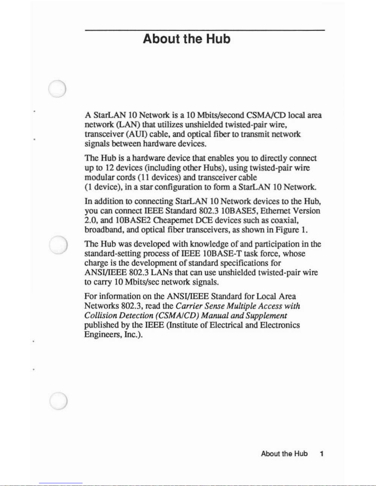
A StarLAN 10 Network is a 10 Mbits/second
CSMNCD
local area
network
(LAN) that utilizes unshielded twisted-pair wire,
transceiver (AUl) cable, and optical fiber to transmit network
signals between hardware devices.
The
Hub is a hardware device that enables you to directly connect
up
to 12 devices (including other Hubs), using twisted-pair wire
modular cords
(II
devices) and transceiver cable
(I
device), in a starconfiguration to form a StarLAN 10 Network.
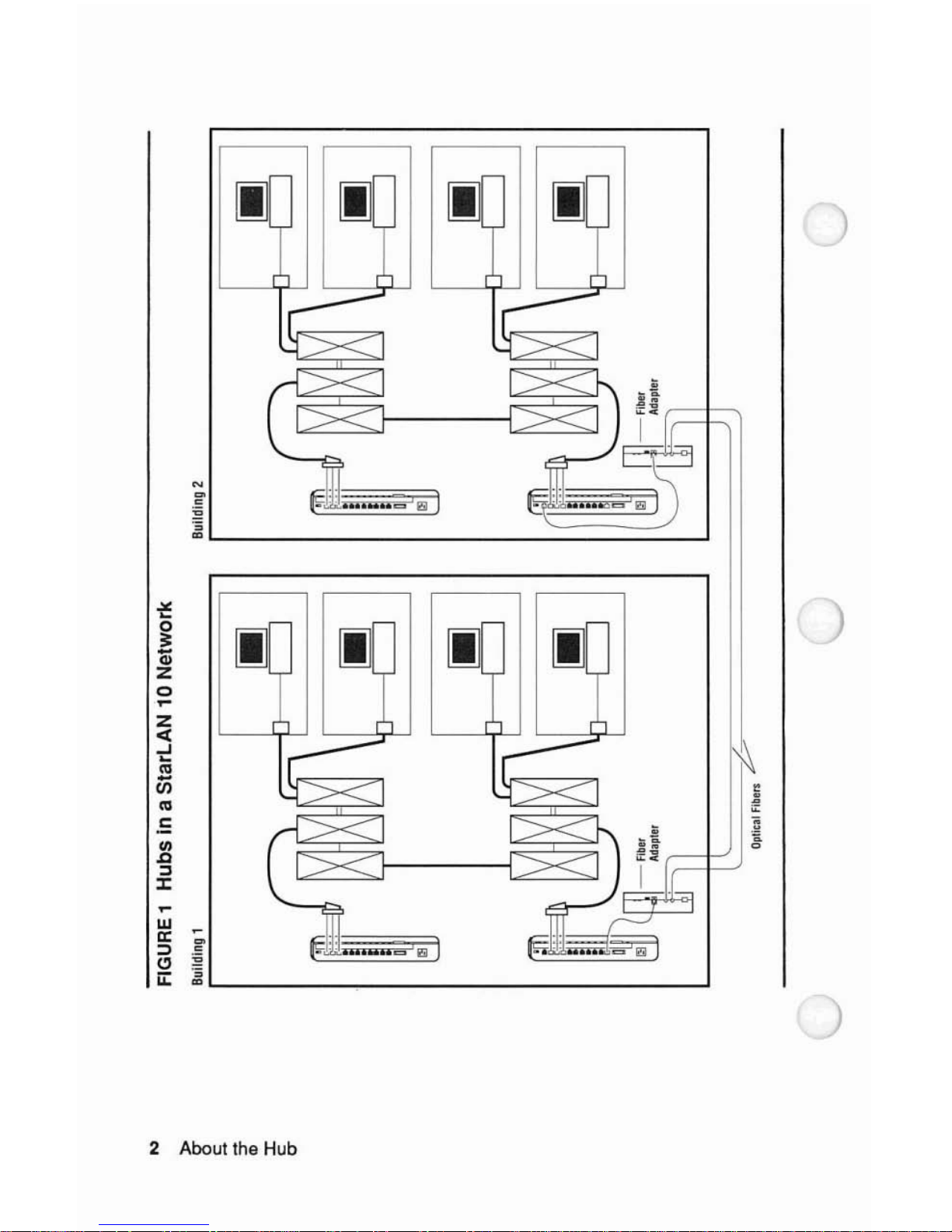
In
addition to connecting StarLAN 10 Network devices to the Hub,
you can connect IEEE Standard 802.3 IOBASE5, Ethernet Version
2.0, and IOBASE2 Cheapemet DCE devices such as coaxial,
broadband, and optical fiber transceivers,
as
shown in Figure I.
The Hub was developed with knowledge
of
and participation in the
standard-setting process
of
IEEE 10BASE-T task force, whose
charge is the development
of
standard specifications for
ANSI/lEEE 802.3 LANs that can use unshielded twisted-pair wire
to carry 10 Mbits/sec network signals.
For
information on the ANSI/lEEE Standard for Local Area
Networks 802.3, read the
Carrier Sense Multiple Access with
Collision Detection (CSMAICD) Manual
and
Supplement
published by the IEEE (InstituteofElectrical and Electronics
Engineers, Inc.).
About the Hub 1
Page 7
IJ IJ
)
-
~
';
:::>
.=
~,;:
.0.0
..
_ " I
(!)
~
u::~'---
---------'
Z
<I:
..J
~
'"
-
til
'"
.S:
III
.c
:::l
J:
2 About
the
Hub
Page 8
)
Features of the Hub
The Hub performs the following functions:
• Distributes Network Signals
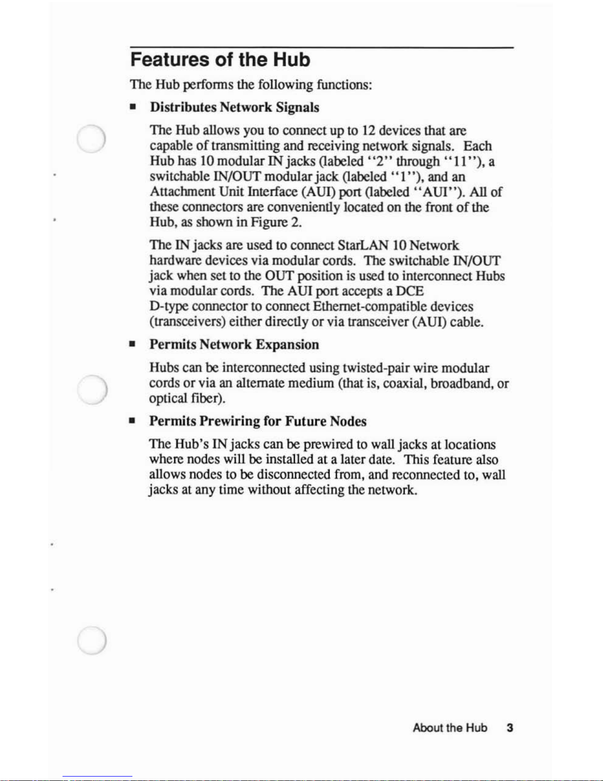
The Hub allows you
to connect up
to
12
devices that are
capable
of
transmitting and receiving network signals. Each
Hub has 10 modular IN jacks (labeled''2"
through'
'II'
'), a
switchable IN/OUT modularjack (labeled
"I"),
and an
Anachment Unit Interface (AUI) port (labeled
"AUI").
All
of
these connectors are conveniently located on the frontofthe
Hub, as shown in Figure 2.
The IN jacks are used to connect StarLAN 10 Network
hardware devices via modular cords. The switchable IN/OUT
jack when settothe OUT positionisusedtointerconnect Hubs
via modular cords. The AUI port accepts a
DeE
D-type connectortoconnect Ethernet-compatible devices
(transceivers) either directly or via transceiver (AUI) cable.
•
Permits
Network Expansion
Hubs can be interconnected using twisted-pair wire modular
cords
or
via an alternate medium (that is, coaxial, broadband, or
optical fiber).
•
Permits
Prewiring
for
Future
Nodes
The Hub's INjacks can be prewired to wall jacks at locations
where nodes will be installed at a later date. This feature also
allows nodes
to
be disconnected from, and reconnected to, wall
jacksatany time without affecting the network.
About the Hub 3
Page 9
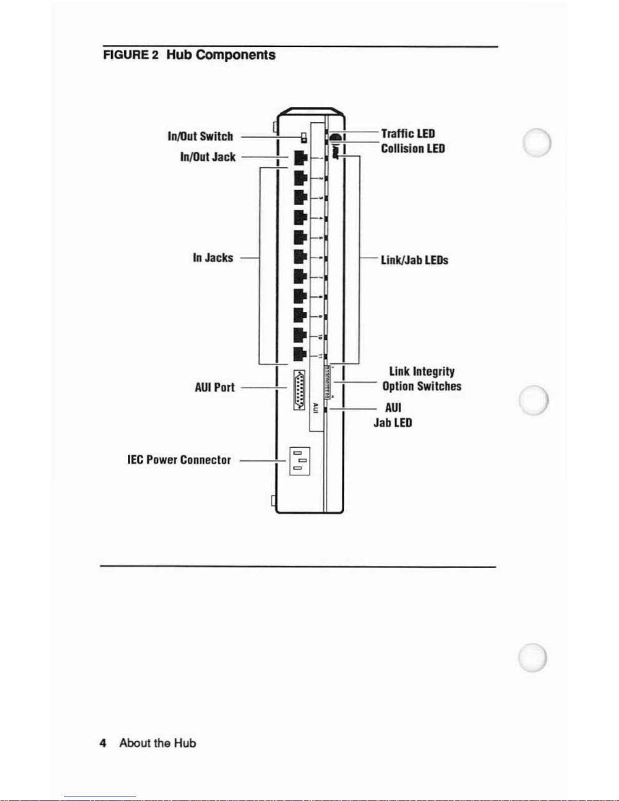
AGURE
2 Hub Components
InllIut
Switch
InlOut
Jack
In
Jacks
AUI
Port
IEC
Power
Connector
4 About the Hub
d
r-
I
I
II
AI
r-~-
..
f--
li~-
..
f-"
..
f-"
..
f-"
..
-"
-
..
f-"
r--
..
f-"
..
f-"
..
"
..
e-,
'-f-"
r-'
I~
t(
~
1.
I
J
~
~
Traffic
LED
Collision
LED
Link/Jab
LEOs
Link
Integrity
Option
Switches
AU!
ab
LED
)
Page 10
)
)
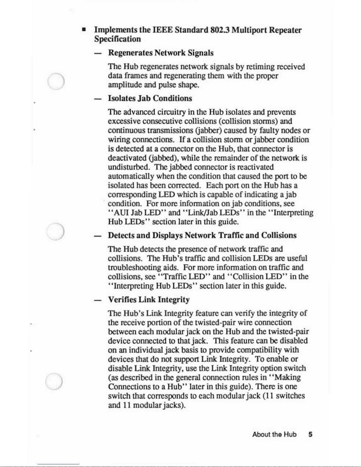
•
Implements
the
IEEE
Standard
802.3
Multiport
Repeater
Specification
Regenerates Network Signals
The Hub regenerates network signals by retiming received
data frames and regenerating them with the proper
amplitude and pulse shape.
Isolates
Jab
Conditions
The advanced circuitry in the Hub isolates and prevents
excessive consecutive collisions (collision storms) and
continuous transmissions Gabber) caused by faulty nodes
or
wiring connections.
If
a collision stormorjabbercondition
is detected at a connector on the Hub, that connector is
deactivated Gabbed), while the remainder
of
the network
is
undisturbed. The jabbed connector is reactivated
automatically when the condition that caused the port to be
isolated has been corrected. Each port on the Hub has a
corresponding LED which is capable
of
indicating a
jab
. condition. For more information
onjab
conditions, see
"AUI
Jab
LED"
and "Link/Jab
LEOs"
in the "Interpreting
Hub LEOs" section later in this guide.
Detects
and
Displays Network Traffic
and
Collisions
The Hub detects the presence
of
network traffic and
collisions. The Hub's traffic and collision LEOs are useful
troubleshooting aids. For more information on traffic and
collisions, see "Traffic
LED"
and "Collision
LED"
in the
"Interpreting Hub
LEOs"
section later in this guide.
Verifies
Link
Integrity
The Hub's Link Integrity feature can verify the integrity
of
the receive portion
of
the twisted-pair wire connection
between each modular jack on the Hub and the twisted-pair
device connected
to
thatjack. This feature can be disabled
on an individual jack basistoprovide compatibility with
devices that do not support Link Integrity. To enable
or
disable Link Integrity, use the Link Integrity option switch
(as described in the general connection rules in
"Making
Connections to a
Hub"
laterinthis guide). Thereisone
switch that corresponds
to
each modularjack
(II
switches
and
II
modularjacks).
Aboutthe Hub 5
Page 11
~
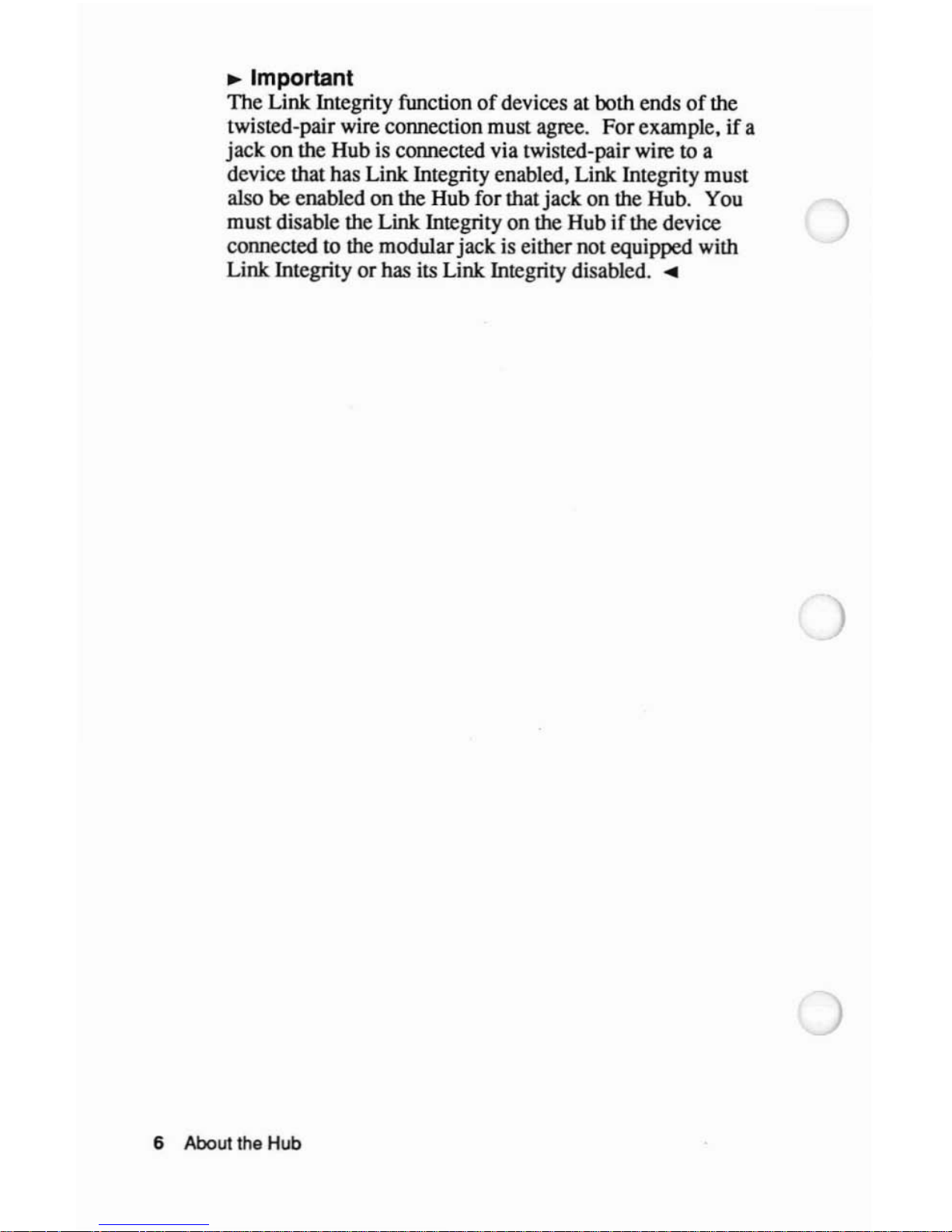
Important
The
Link Integrity function
of
devices at both endsofthe
twisted-pair wire connection must agree.
For
example.ifa
jack
on
the Hub is connected via twisted-pairwire to a
device that has
Link Integrity enabled. Link Integrity must
also
be
enabled
on
the Hub for that
jack
on
the Hub. You
must
disable the Link Integrity
on
the Hubifthe device
connected to the modular
jack
is either
not
equipped with
Link Integrity
or
has its Link Integrity disabled.
~
6 About the Hub
Page 12
)
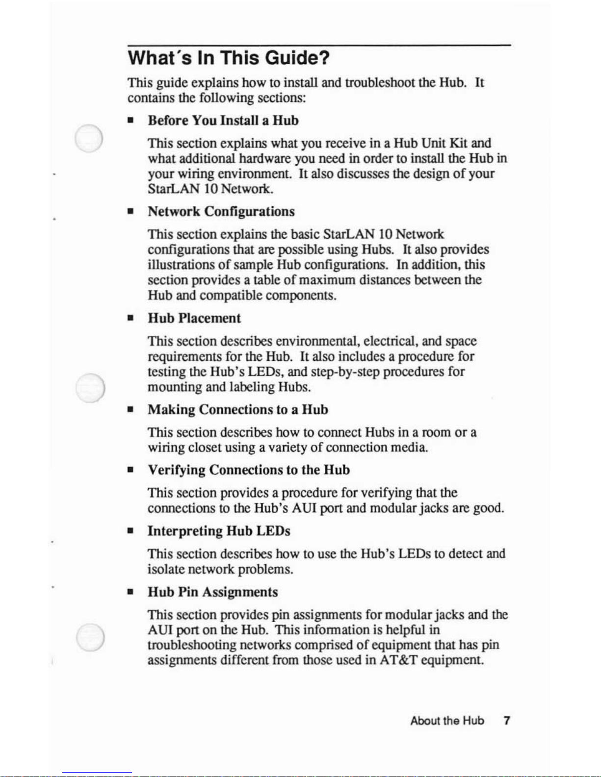
What's
In
This Guide?
This guide explains how to install and troubleshoot the Hub.
It
contains the following sections:
• Before You Install a
Hub
This section explains what you receive in a Hub Unit Kit and
what additional hardware you need in ordertoinsla1l
the Hub in
your wiring environment.
It
also discusses the designofyour
StarLAN 10 Network.
• Network Configurations
This section explains the basic StarLAN 10 Network
configurations that
are
possible using Hubs. It also provides
illustrations
of
sample Hub configurations. In addition, this
section provides a table
of
maximum distances between the
Hub and compatible components.
•
Hub
Placement
This section describes environmental. electrical, and space
requirements for the Hub.
It
also includes a procedure for
testing the Hub's LEDs. and step-by-step procedures for
mounting and labeling Hubs.
•
Making
Connections to a
Hub
This section describes how to connect Hubs in a room
or
a
wiring closet using a variety
of
connection media.
• Verifying Connections to the
Hub
This section provides a procedure for verifying that the
connectionstothe Hub's AU! port and modular jacks are good.
•
Interpreting
Hub
LEOs
This section describes how to use the Hub's LEDs
to
detect
and
isolate network problems.
•
Hub
Pin
Assignments
This section provides pin assignments for modularjacks and
the
AU! port
on
the Hub. This information is helpful in
troubleshooting networks comprisedofequipment that has pin
assignments different from those used in
AT&T
equipment.
About the Hub 7
Page 13

• Glossary
This section explains technical teons for readers who are
unfamiliar with communications wiring environments and local
area networlcs.
8 About the Hub
Page 14
)
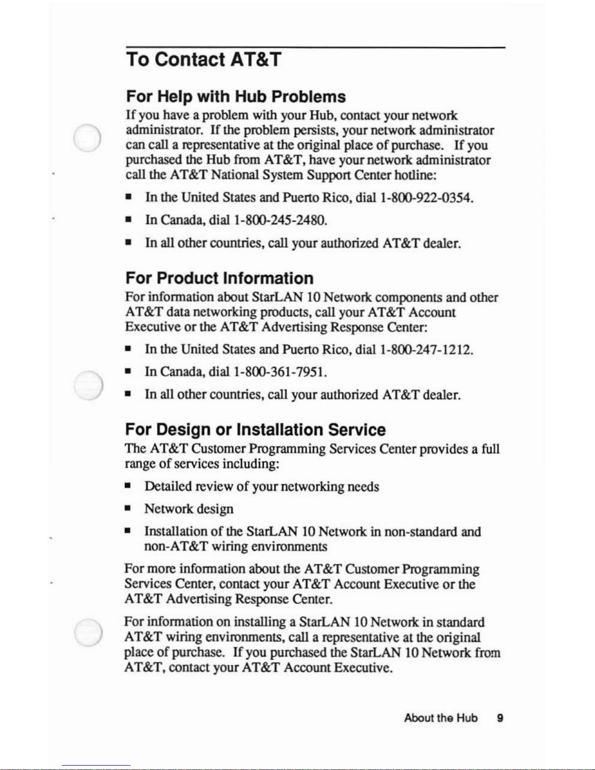
To Contact AT&T
For Help with Hub Problems
If
you have a problem with your Hub. contact your networl<
administrator.
IT
the problem persists. your
networl<
administrator
can call a representative at the original place
of
purchase.
IT
you
purchased the Hub from AT&T. have yournetwork administrator
call the AT&T National System Support Center hotline:
• In the United States and Puerto Rico. dial 1-800-922-0354.
• In Canada. dial 1-800-245-2480.
•
In
all other countries. call your authorized AT&T dealer.
For Product Information
For
information about StarLAN 10 Networl< components and other
AT&T data networking products. call your AT&T Account
Executive
or
the AT&T Advertising Response Center:
• In the United States and Puerto Rico. dial 1-800-247-1212.
•
In
Canada. dial 1-800-361-7951.
•
In
all other countries. call your authorized AT&T dealer.
For Design or Installation Service
The AT&T Customer Programming Services Center provides a full
range
of
services including:
• Detailed review
of
yournetworking needs
• Network design
• Installation
of
the StarLAN 10
Networl<
in non-standard and
non-AT&T wiring environments
For more information about the AT&T Customer Programming
Services Center. contact your AT&T Account Executive
or
the
AT&T Advertising Response Center.
For
information on installing a StarLAN 10 Networl< in standard
AT&T wiring environments. call a representative at the original
place
of
purchase.
IT
you purchased the StarLAN 10 Network from
AT&T. contact your AT&T Account Executive.
About the Hub 9
Page 15
)
)
Before You Install a Hub
Before installing a Hub, you should verify the contentsofthe
Hub
Unit
Kit
and detennine what,ifany, additional hardware is
required to install the Hub.
You
also should contact your network
administrator for a copy
of
the network configuration design and
for
any
additional hardware required for the installation.
Design Considerations
To
ensure proper installationofthe StarLAN 10 Network, you
should have a network configuration design that specifies all
of
the
components to be installed
in
each room and wiring closet
(if
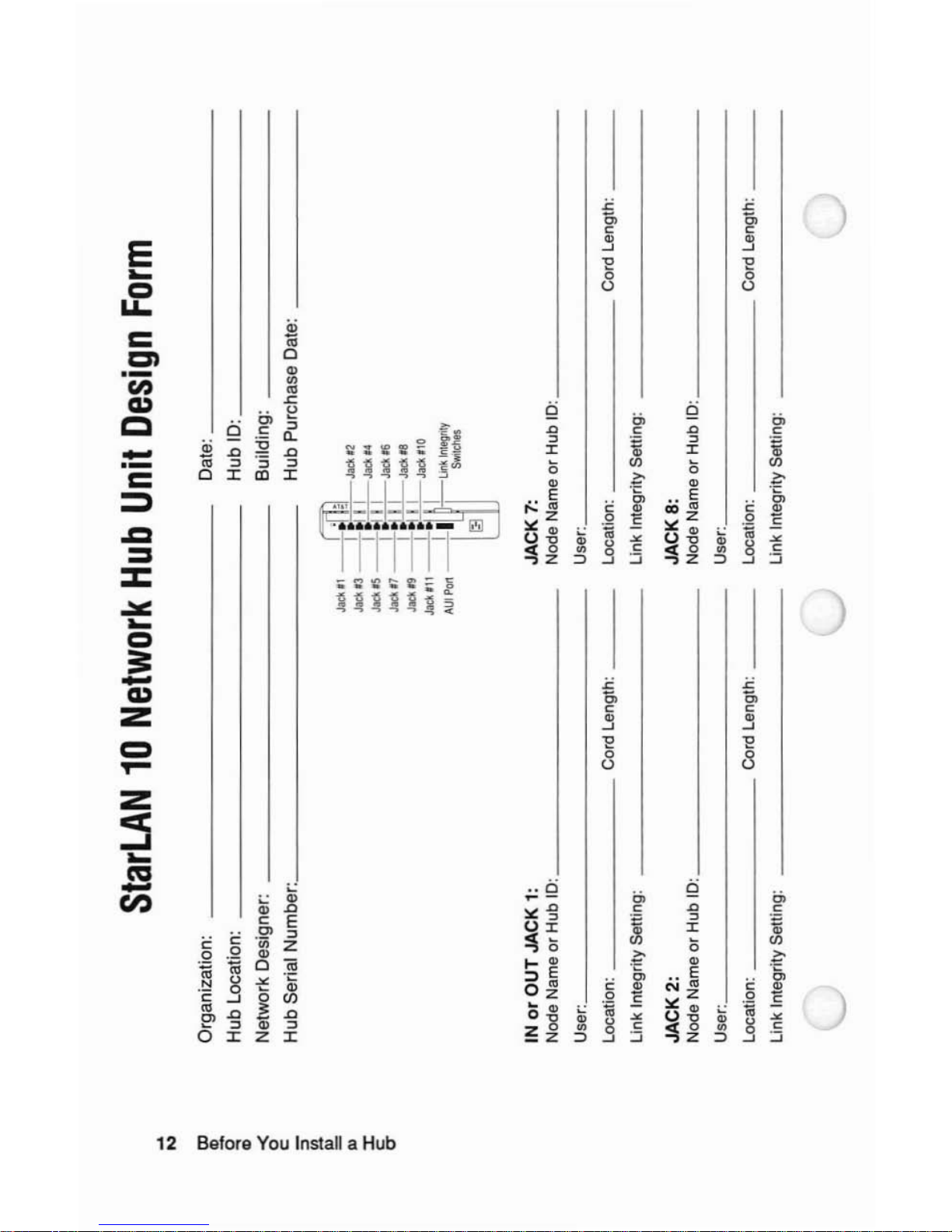
applicable).
The
StarLAN 10 Network Hub Unit Design Form,
shown
on
the next page, is used to identify the hardware devices
to
be connected to a Hub.
If
you
don't
have a network configuration design, it is important for
you to realize that there are maximum distance and delay
guidelines associated with a StarLAN 10 Network.
Your
network
must
confonn
to these distance and delay guidelines.
If
you are installing a StarLAN 10 Network that will use the
building's existing twisted-pair wiring, you also should have a
basic understanding
of
the wiring environment in which you intend
to install components.
For
infonnation
about
StarLAN 10 Network configurations, read
the
"Network
Configurations" section in this guideorrefer to the
StarLAN 10 Network Hardware Design Guide.
Before You Install a Hub
11
Page 16
~
.,
StarLAN
10
Network
Hub
Unit
Design
Form
Jack.1
--;
:1
gl
JadI,2
Jack
n
--[:1
1_1_
J
acl\,4
Jack
.5
--I
tJ
1_1_
Jadl
'6
Jack,7
--I
:11_1_",,,,
Jacklr9
--I
tJ
'_I_Jack.IO
JacUll
--~I
L
Unk
Inlegrity
AUI
Porl
--
SWilches
Ii3
'"
~
CD
~
c:
:;-
!e
g!,
..
:I:
c:
C"
Organization:
Hub
Location:
Network Designer:
Hub
Serial Number: _
Date: _
Hub
10:
_
Building:
Hub
Purchase Date: _
Cord Length: _
Cord Length: _
IN
or
OUT JACK
1:
Node Name
or
Hub
10:
_
User: _
Location: Cord Length: _
Link
Integrity
Setting:
JACK 2:
Node
Name
or
Hub
10:
_
User: _
Location: Cord Length: _
Link
Integrity
Setting:
JACK
7:
Node Name or Hub
ID:
_
User: _
Location:
_
Link
Integrity
Setting:
JACK 8:
Node Name
or
Hub 10: _
User: _
Location:
_
Link
Integrity
Setting:
Page 17

'---"
"'--'
J
JACK
3:
JACK
9:
Node
Name
or
Hub
10:
Node
Name
or
Hub
10:
User: User:
Location:
Cord Length: Location: Cord Length:
Link Integrity Setting:
Link Integrity Setting:
JACK
4:
JACK
10:
Node
Name
or
Hub
10:
Node
Name
or
Hub
10:
User: User:
Location:
Cord Length: Location: Cord Length:
Link Integrity Setting:
Link Integrity Setting:
JACK
5:
JACK
11:
Node
Name or
Hub
10:
Node
Name
or
Hub
10:
User: User:
Location:
Cord Length: Location:
Cord
Length:
'"
Link
Integrity Setting: Link Integrity Setting:
~
iii
JACK
6:
AUI PORT:
~
Node
Name
or
Hub
10:
Node Name
or
Hub
10:
c
5"
User:
User:
~
location:
Cord
Length:
Location:
Cord Length:
~
III
Link Integrity Setting:
::I:
c
Notes:
CT
~
Col
Page 18

What's Supplied in a Hub Unit Kit?
The Hub Unit Kit. illustrated in Figure 3. contains the following
components:
a
AHub
b A bracket for mounting the Hub on the wall
C Four wall anchor.; for mounting the Hub on wallboard
d Four
No.8
X I-inch (2.5 centimeter) panhead sheet-metal
screwstohold the bracket on the wall
e A UL/CSA listed SIT-type power cable for connecting the
Hub's internal power supplytocommercial power
If
any
of
the items are missingordamaged. return the kit to the
original placeofpurchase.
14 Before You Install a Hub
Page 19
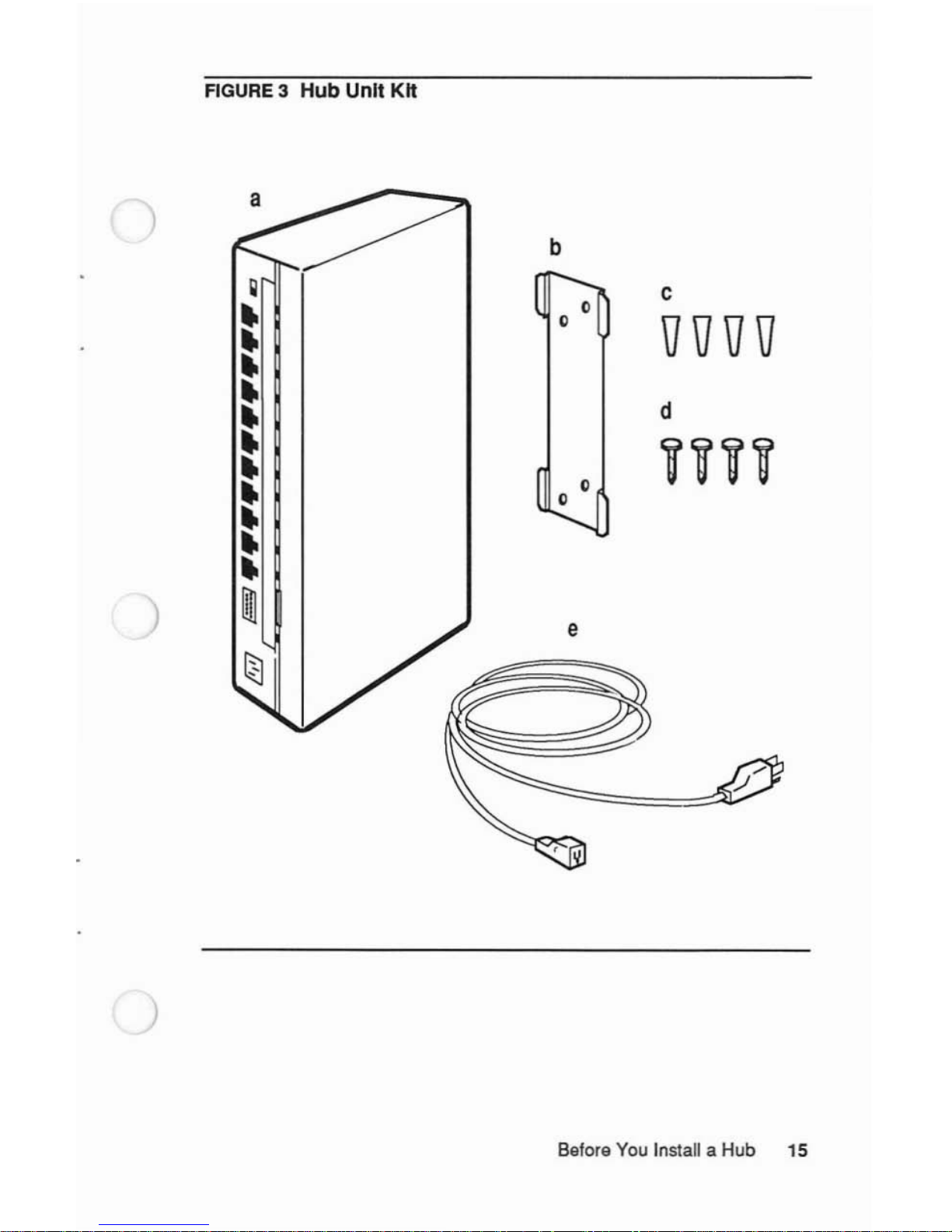
FIGURE3Hub
Unit Kit
)
B8for8 You Install a Hub 15
Page 20
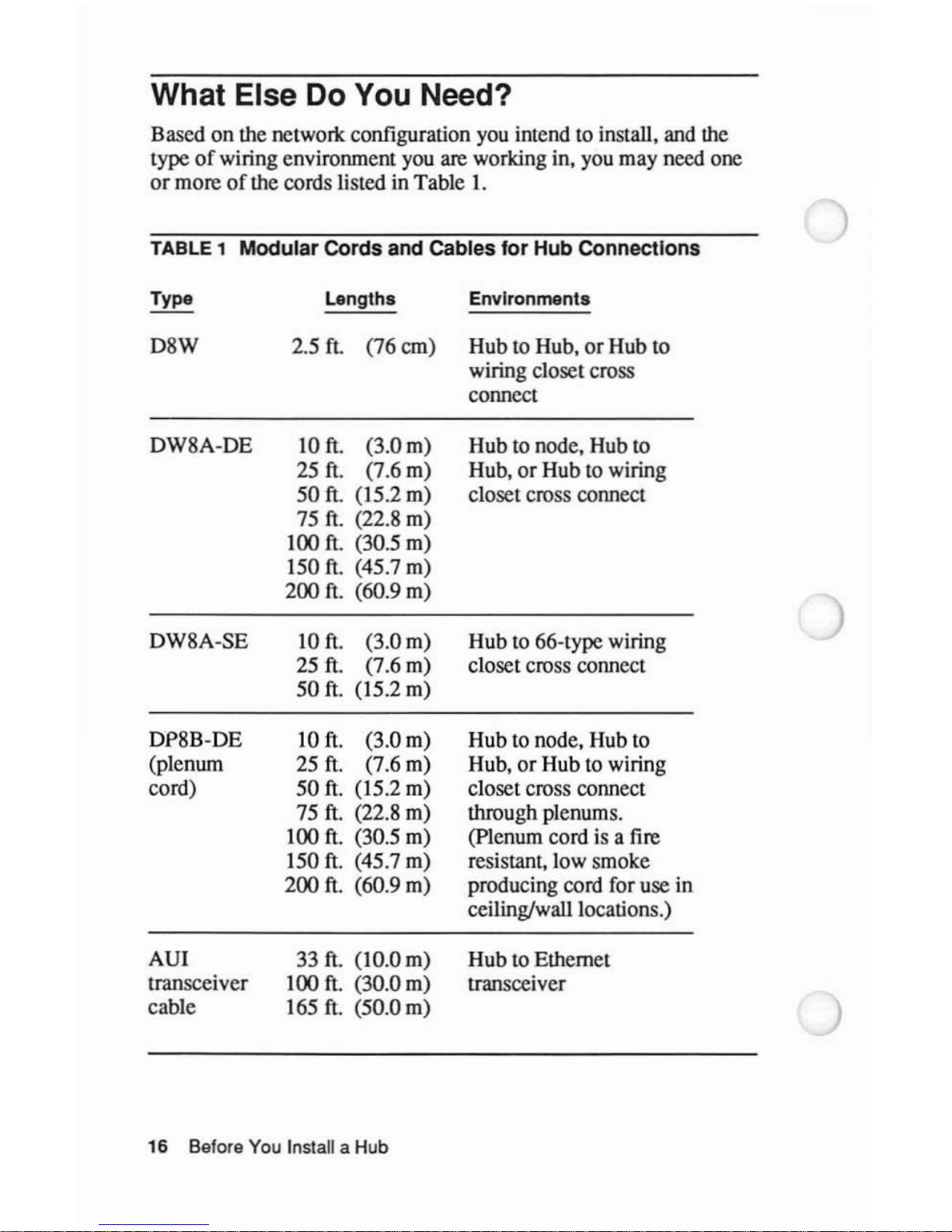
What Else Do You Need?
Based on the network configuration you intend to install. and the
type
of
wiring environment you are working in. you may need one
or
moreofthe cords listed in Table I.
TABLE
1 Modular Cords and Cables for Hub Connections
Type
Lengths
Environments
D8W
2.5
ft.
(76 em) Hub to Hub,orHub to
wiring closet cross
connect
DW8A-DE
10
ft.
(3.0 m)
25
ft.
(7.6
m)
50
ft. (15.2
m)
75
ft.
(22.8 m)
100 ft. (30.5 m)
150 ft. (45.7 m)
200
ft. (60.9 m)
DW8A-SE
10
ft.
(3.0 m)
25
ft.
(7.6 m)
50
ft.
(15.2 m)
DP8B-DE
10
ft.
(3.0 m)
(plenum
25
ft.
(7.6 m)
cord)
50
ft.
(15.2 m)
75
ft.
(22.8 m)
100
ft.
(30.5 m)
150
ft.
(45.7 m)
200
ft.
(60.9 m)
AU!
33
ft. (10.0
m)
transceiver
100
ft.
(30.0 m)
cable
165
ft.
(50.0 m)
Hub to node. Hub to
Hub.
or
Hub to wiring
closet cross connect
Hub
to 66-type wiring
closet cross connect
Hub to node, Hub to
Hub,
or
Hub to wiring
closet cross connect
through plenums.
(plenum cord is a fire
resistant, low smoke
producing cord for use in
ceiling/wall locations.)
Hub
to Ethernet
transceiver
16
Before You Install a Hub
Page 21
)
)
)
Your installation also may require oneormoreofthe following:
• 356A Adapter (11O-type wiring
closet)-used
to connect
modular cords to a 25-pair cable.
• 451A Adapter (Hub to
node)-used
to join two modular cords.
• Fiber Adapter (Hub to
Hub)-
used to connect modular cord
to
optical fiber.
• Power strip---used to connect more than one Hub to a single
electrical receptacle.
• A UL/CSA listed SIT-type extension cord to connect a Hub to
an electrical receptacle that is more than 7 feet away from the
Hub.
•
If
you intend to access commercial power via a 220 volt outlet,
you must purchase and use a UL/CSA listed 220 volt power
cord
of
the appropriate length, type SIT, 3 conductor,
18AWG,
configured for NEMA6-15.
• Rack mounting bracket--used to mount multiple Hubs, Fiber
Adapters, and Fiber Hubs.
If
you do not have the appropriate hardware for your installation,
have your network administrator call your AT&T Account
Executive
or
the AT&T Advertising Response Center.
Before
You
Install a Hub 17
Page 22
)
)
)
Network Configurations
The Hubiscompatible with all StarLAN 10 Network components.
The Hub supports a variety
of
industry standard IEEE 802.3
IOBASE5, Ethernet, and IOBASE2 Cheapernet DCE devices such
as coaxial, broadband, and optical fiber transceivers. The Hub also
supports the IOBASE-T standard specifications currently being
developed by the IEEE IOBASE-T task force for ANSlIIEEE 802.3
LANs utilizing unshielded twisted-pair wire media
at a IOMbit/sec
transmission rate.
All StarLAN 10 Networks, regardless
of
their size, are installed in
a star
or
multiple-star configuration. In a StarLAN 10 Network
with more than one Hub, each Hub
is
considered a peer (there is no
hierarchy relative to the distribution
of
traffic over the network).
However, when you install a StarLAN 10 Network that uses
building wire, that building wire typically is installed in a
hierarchical fashion (that is, rooms are wired to satellite wiring
closets, which are in tum wired to an equipment room).
In
such
cases, it is important
to understand that any resulting hierarchical
configuration
of
the StarLAN 10 Network is due to the physical
arrangement
of
the building wire.
Network Configurations 19
Page 23
Hub Locations
You can install a Hub in a roomora wiring closet:
•
If
you are supporting a small networlc (confined to a room)
or
if
there are more devices in the room than available wall jacks,
you should install the Hub in the room.
•
If
you are supporting a larger network (distributed throughout a
floor
or
a building), you should install the Hubs in wiring
closets.
When you install a Hub in a room, you directly connect a device to
the Hub using a modular cord
or
a transceiver (AUI) cable.
When you install a Hub in a wiring closet. you connect a device to
the Hub using a combination
of
media: modular cords, building
twisted-pair wires. optical fiber,
or
transceiver (AUI) cable.
Typical room and wiring closet configurations are discussed in the
next section,
••
Sample Networlc Configurations."
20 Hub Configurations
Page 24
)
)
Sample Network Configurations
This section contains sample StarLAN 10 Networlc configurations.
Each configuration is subject to maximum distance and delay
guidelines that must be observed in order for the network to
function properly.
The following sections contain information about maximum
distance and delay guidelines:
•
For
information on maximum distances between various
devices connected to a Hub. see the "Distance Guidelines for
Connections to a
Hub"
section in this guide.
•
For
information on the maximum distances and delay
guidelines for StarLAN
10
Networlcs in general, see the
StarLAN 10 Network Hardware Design Guide.
Network Configurations
21
Page 25
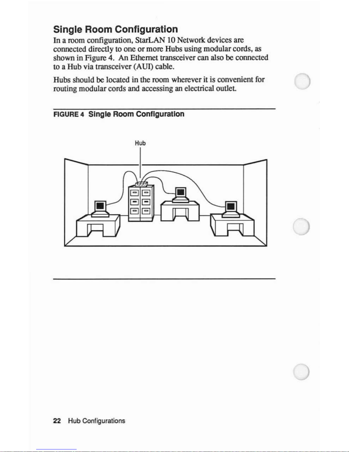
Single Room Configuration
In
a room configuration, StarLAN 10 Networlc devices are
connected directly to one
or
more Hubs using modular cords,
as
shown in Figure 4. An Ethernet transceiver can also
be
connected
to a Hub via transceiver (AUI) cable.
Hubs should
be located in the room wherever it is convenientfor
routing modular cords and accessing an electrical
outlet
FIGURE
4 Single Room Configuration
Hub
22
Hub Configurations
Page 26
)
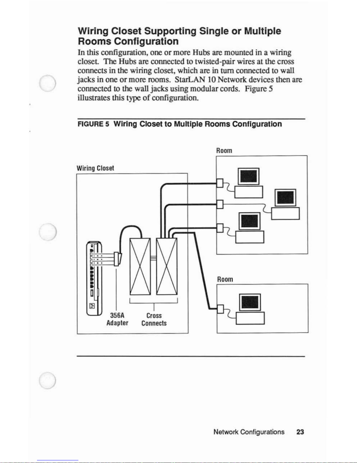
Wiring Closet Supporting Single or Multiple
Rooms Configuration
In
this configuration, oneormore Hubs are mounted in a wiring
closet
The Hubs are connected to twisted-pair wires at the cross
connects in the wiring closet, which are in tum connected to wall
jacks
in one
or
more rooms. StarLAN 10 Network devices then are
connected
to the wall jacks using modular cords. Figure 5
illustrates this type
of
configuration.
FIGURE
5 Wiring Closet to Multiple Rooms Configuration
Room
)
)
Wiring
Closet
I
356A
Cross
Adapter
Connects
Room
Network Configurations 23
Page 27
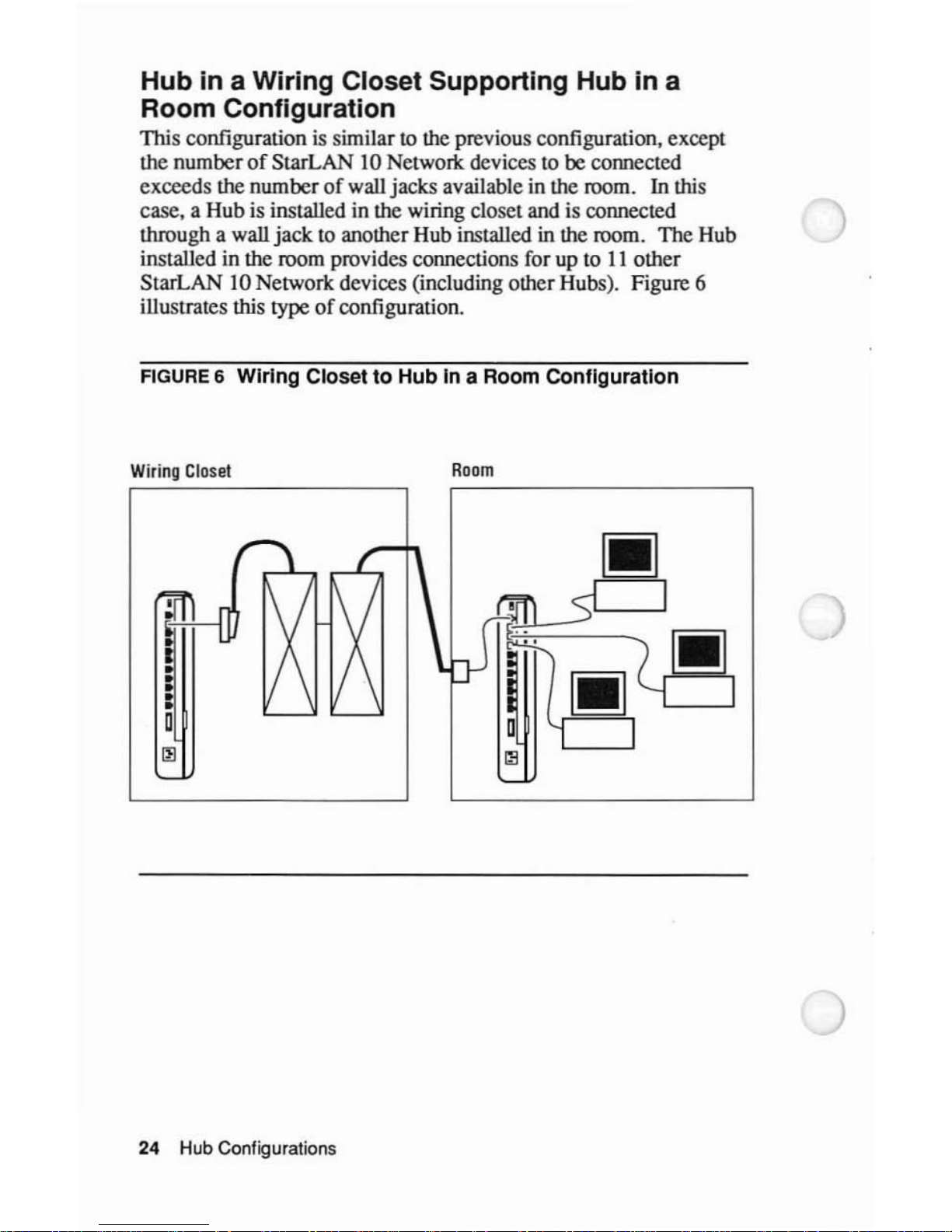
Hub in a Wiring Closet Supporting Hub in a
Room Configuration
This configurationissimilar to the previous configuration, except
the number
of
StarLAN 10 Networlc devices to be connected
exceeds the number
of
wall jacks available in the room. In this
case, a Hub is installed in the wiring closet and is connected
through a wall
jack
to another Hub installed in the room. The Hub
installed in the room provides connections for up to
II
other
StarLAN 10 Network devices (including other Hubs). Figure 6
illustrates this
type
of
configuration.
FIGURE
6 Wiring Closet to Hub in a Room COnfiguration
Wiring
Closet
Room
I
•
•
•
:
o
~
24
Hub Configurations
Page 28
)
)
Multiple Wiring Closet Configuration
In this configuration. Hubs installed in wiring closets (that provide
service to different areas
or
floorsofthe building) are connected
together using building wire and/or optical fiber to create a singIebuilding-wide StarLAN
IO
Network,
as
shown in Figure 7.
Optical fiber is an ideal medium for interconnecting Hubs in
different wiring
closets-
offering both increased working
distances and network transmissions free
of
electrical noise
generated by other devices in the building. When connecting Hubs
via optical fiber, a StarLAN
IO
Network Fiber Adapter is required
for each Hub-to-optical fiber pair, as shown in Figure
8.
Network Configurations
25
Page 29

FIGURE
7 MUltiple Wiring Closet Configuration
R
W"
CI
t
iring
ose
oom
[II
/
\-,
I
I
,.1L:-
/-l
..-
&I
IX
1\
/
1\/
Room
[:,
..
c::'
M •
[II
•
•
1/
\
1/
\
•
Ii
\
•
L..
....
'-- '--
\-,
I
•
•
/-l
D
~
"-
Wiring
Closet
Room
[II
h
I
..L::-n
~
~'-
~
rmI
IX
:X
:x
Room
•
...
[II
...
•
•
•
\h
I
\..'--
'--
I
•
•
~
D
~
'-
26 Hub Configurations
Page 30

FIGURE
8 Multiple Wiring Closet Configuration Using Optical
Fiber
Fiber
Adapter
•
/"
h
I
~/
~
,..I..t:;-
f-'
~
X
X
IX
Room
•
I
,-
......
\
'-- '--
'---'
h
I
~
D
f-'
III
'-
Wiring
Closet
Room
Fiber
Adapter
•
h
I
~/
,-----
.----,
I I
.-
f-'
X
IX IX
Room
rl=t
•
...
'-
......
\.'--
'---'
h
I
f-'
-
D
III
'-
)
)
)
Wiring
Closet
Room
Networl<
Configurations 27
Page 31

Building-to-Building Configuration
In
this configuration. Hubs installed in wiring closetsofdifferent
buildings are connected together using optical fiber to fonn a
building-to-building StarLAN
IO
Networlc. This configuration
requires a StarLAN
IO
Networlc Fiber Adapter for each Hub-to-
optical fiber pair connection.
Figure 9 illustrates this type
of
configuration.
28
Hub Configurations
Page 32

)
c
.2
)
1U
~
::I
Cl
:;::
C
0
U
Cl
c
:E
::I
a:l
,
0
-
c.
c
:g
::I
a:l
'"
W
II:
::;)
Cl
u::
)
-
- - -
-'-,
-'-, r,
n
~><
~
><
1><
~!
1><
><
rrr
@
,:I
...._..
~
" )
~~
...
~-:b
-
-0
- -
l l
-'-,
f><1
r:
Y><
I
><
1
I><h
~i(
1><
><1
\...
1
II
Jiw.w
..
_"
I
@~
Network Configurations 29
Page 33

Distance Guidelines for Connections
to a Hub
Regardlessofthe network configuration you choose, whenever you
connect a device
to
a Hub. certain distance guidelines must be
observed. These guidelines vary accordingtothe typeofdevice
being connected and the connection medium being used.
Table 2 provides maximum distances for connections between a
Hub and various other devices.
TABLE
2 Wire
and
Transceiver
Cable Distance Guidelines
Distance
Medium Connection Feet Meters
Wire Hub-to-NAU
328*
100*
Wire Hub-to-Hub
328*
100*
Wire Hub-to-AUI
328*
100*
Adapter
Wire Hub-to-Coax
328*
100*
Adapter
Wire
Hub-to-Bridge
328*
100*
Wire Hub-to-Fiber
49
15
Adapter
Transceiver
Hub-to-
164 50
(AUI) Cable Ethernet
Transceiver
• Distance includes
Hub·lO·Cross
CmneCl
Field(s)
30 Huli.Configuralions
Page 34

)
)
)
Hub Placement
You can set a Hub (horirontally) on a level surface (for example. a
table top. a
fl1ing
cabinet,ora desk top) or mount it (verticaIly) on
a waIl.
Before placing a Hub in a room
or
wiring closet. you must
determine
if
the environmental. electrical. and space requirements
for the Hub are satisfied.
Hub Placement
31
Page 35

Placement Considerations
You can place
oneormore Hubs in roomsorwiring closets that
satisfy the conditions described
in
the following steps:
1 Determine whether the operational environment for the Hub
meets the following specifications:
Temperature:
Humidity:
Altitude:
oto
50
°C
32 to 122
of
5% to 95% NC
oto 10.000 feet
oto 3.017 meters
~
Note
Where the operational environment differs significantly from
the environment in which the Hub was stored. wait at least two
hours before installing the Hub.
...
32 Hub Placement
Page 36

2 Be sure thereisa commercial power receptacle within a 7-foot
(2.2-meter) cord distance
of
the Hub.
If
there is no convenient
location within 7 feet (2.2 meters)
of
a receptacle. use a power
strip
or
grounded extension cord to extend the range
of
your
powercable.
The
power requirements for a Hub
are:
Voltage:
Frequency:
Power:
85 to 250 VAC
47
to 63Hz
35W
)
)
The power receptacle must be a non-switched. 3-pronged.
grounded receptacle. There
are
no voltage switches
on
the
Hub. It operates continuously from 85 to 250 VAC.
•
WarnIngs
a Do not use a 3-to-2-pronged adapter at the receptacle; use
of
this typeofadapter may result in electrical shock and/or
damage to the Hub.
b The detachable powercable shipped with the Hub Unit Kit
is
rated only 125 VAC.
If
you intend to access commercial
powervia a 220 volt outlet. you must purchase and use a
UL/CSA listed 220 volt power cable. type SIT. 3 conductor.
18
AWG. configured forNEMA6-I5.....
Hub Placement 33
Page 37

3
Be
sure to allocate enough space for
• the Hub. A
Hub's
dimensions, including the mounting
bracket, are:
16.5 inches (42 centimeters) in height
3 inches
(8
centimeters) in width
7 inches (18 centimeters) in depth
• the cords that will be connected to the Hub (including the
powercable).
• air circulation.
When you mount a Hub on the wall, allow 5 inches (12
centimeters)
of
clearance between the topofa Hub and
any other object.
When you set a Hub on a level surface, allow 5 inches
(12 centimeters)
of
clearance between the Hub and any
object positioned overthe Hub. Never place an object
directly on top
of
the Hub.
If
you are installing more than one Hub in the same location, it is a
good idea to locate Hubs close to one another to simplify
administration and troubleshooting tasks,
as
shown in Figure 10.
If
you are mounting multiple StarLAN 10 Network wiring devices
within a closet, you may want
to consider rack mounting them.
~
Note
Do
not stack Hubs on topofeachother. Stacking will affect the
heat dissipation capabilities
of
the Hubs.
~
The
next section describes a procedure for mounting a Hub on a
wall in a room
or
wiring closet.
If
you are not mounting your Hub
on
the wall, simply follow Steps 6, 7, and 8ofthe following
procedure.
34
Hub Placement
Page 38

FIGURE
10
Collocating Hubs In a Room
or
Wiring Closet
ij
•
,-----------------
~
I
~----------
~
,
,.-
-!)
•
•
•
•
•
•
•
o
~
~
B B
B
...
-€>
...
-€>
--
~
•
•
•
•
•
•
• •
•
• •
•
• •
•
)
•
• •
• •
•
•
•
•
• •
•
• •
•
0 0
0
~
~
~
)
Hub Placement 35
Page 39

How to Mount a Hub
The following procedure describes how to mount a Hub onto
wallboard
or
wood (a stud. heavy wooden paneling. etc.) using the
hardware provided in the Hub Unit
Kit.
If
you are mounting a Hub
on a wall other than the types mentioned above (for example. a
masonry wall). you may need additional mounting hardware.
To mount a Hub. the only tools you need are a flat-blade
screwdriver and a drill with a 3/16-inch bit (when mounting onto
wallboard)
or
a liS-inch bit (when mounting onto wood).
If
you are not mounting your Hub
on
a wall (that is. it will siton a
level surface). skip ahead to Step 6
of
this procedure.
To mount a Hub. follow these steps:
1 Slide the mounting bracket out
of
the Hub.asshown in
Figure
II.
FIGURE
11
Removing
the
Bracket from the Hub
36 Hub Placement
•
Page 40

)
)
2 Position the bracket on the wall, and carefully mark the location
for each screw with a pencil. The bracket can be mounted with
either end up.
3 Mount the bracket, as shown in Figure
12.
•
If
you are mounting the bracket onto wallboard between
studs:
a Drill four holes for the wall anchors, using a 3/16-inch
bit.
b Insert the wall anchors
and
lightly tap them into place
until they are flush with the wall.
e Position the mounting bracket on the wall so that the
four holes in the bracket line up with the anchors
you
have inserted.
d Insert the sheet-metal screws through the holes in the
mounting bracket and into the wall anchors.
e Screw the mounting bracket onto the wall.
•
If
you are mounting the bracket onto wood:
a Drill four holes for the sheet-metal screws, using a
1/8-
inch bit.
b Position the mounting bracket on the wall so that the
four holes in the bracket line up with the holes you have
drilled.
e Insert the sheet-metal screws through the holes in the
mounting bracket and into the drilled holes.
d Screw the mounting bracket onto the wall.
Hub Placement
37
Page 41

FIGURE
12
MountIng the Bracket
0
OJ OJ
0
(Wall
anchors
for
wallboard
mounting
only)
--'OJ
6-
e
--
OJ
4 Place the Hub finnly against the wallsothat the mounting
bracket fits into the slots on the back
of
the Hub.
38 Hub Placement
Page 42

5 Slide the Hub down on the bracket,asshown in Figure
13,
until
it locks into place.
FIGURE
13
Placing the Hub
on
the
Bracket
)
)
--
I II
-.,.
III
II
11
.., 0
II
I v
I I
I I
I n I
I U I
I I
I I
I I
I I
~
I
III
0 J
ill
~
11
..........
II
.....
Hub Placement 39
Page 43

6 Connect the powercable to the 3-prong
lEC
powerconnector
on the front
of
the Hub, as shown in Figure 14.
FIGURE
14
COnnecting the Power
cable
7 Insert the otherendofthe power cable into a grounded outlet
on
the wall, a power strip, or a grounded extension cord.
~
Warning
Do not use a 3-to-2-pronged adapter at the outlet; useofthis
type
of
adapter may result in electrical shock and/or damage to
the Hub.....
8 Repeat Steps 1 through 8 for each Hub to
be mounted (Steps 6
through 8 for freestanding Hubs).
Once the Hubs are properly placed in the room
or
wiring closet,
you should perform the power-up LED test in the next section.
40 Hub Placement
Page 44

Power-Up LED Test
Once the
Hub
is mounted, you should verify that its
LEDs
are
functioning properly
by
using the procedureinthis section. Figure
15 illustrates
all
of
the
LEDs
on the Hub.
FIGURE
15
Hub
LEOs
)
-
._1
'I
"".
..
.!.L
..
- .
..
·
..
·
..
·
..
·
-
..
-.
..
-.
..
- .
..
-,
..
-,
"~
-
~
.
l,
•
"
-
~
[
Traffic
LEO
Collision
LEO
link/Jab
LEOs
AUI
Jab
LEO
Hub Placement
41
Page 45

Procedure
To
verify that
the
Hub's
LEDs are functioning properly, follow
these steps:
1 Remove the powercable from the Hub.
2 Plug the powercable back into the Hub and observe the LED
activity on the Hub:
a
For
approximately two seconds after power is initially
applied, the following LED activity should occur.
LED
LED
Slale
Traffic
OFF
Collision
ON
Link/Jab
ON
RED
AUIJab
ON
b After two seconds,
the
LEDs should return to their normal
states.
LED
LED
Slale
Traffic ON
Collision OFF
Link/Jab OFF
(ON AMBER
if
Link
Integrity is disabled)
AUIJab
OFF
~
Note
If
you are running this test with any
of
the twisted-pair wire
jacks connected, the status
of
the Link/Jab LED may vary.
Therefore, it is recommended that you disconnect all jacks
before performing the power-up LED
test
....
42 Hub Placemenl
Page 46

)
)
If
all LEOs followed the described sequence, then the Hub's
LEOs are operating properly.
If
there is a deviation from
the described sequence, proceed as follows depending on
the deviation:
•
If
all LEOs remained OFF, determine whether the power
source is functioning by plugging another device into
the receptacle. Then do
one
of
the following:
If
the receptacle is not providing power, plug the
Hub
into another receptacle known to have power.
If
the receptacle is providing power and allofthe
Hub's
LEOs remain OFF, check the connection
between the Hub and the powerreceptacle by
following these steps:
a Unplug the Hub from the receptacle.
b Oisconnect the female connector on the power
cable from the IEC Power Connector on the front
of
the Hub.
eRe-insert
the female connector into the IEC
Power
Connector.
d Plug the Hub into the receptacle.
If
all
of
the LEOs remain OFF. either the Hub
or
the power cable is not operating properly.
Contact a representative at the original place
of
purchaseora Service Technician.
Hub Placement
43
Page 47

•
If
there are any otherdeviations from the power-up
sequence in Step 2b. return the Hub
to
the original
place
of
purchase.
If
you purchased your Hub from
AT&T:
In the United States and Puerto Rico. call the
toll-free
AT&T
National System Support Center
hotline
at
1-800-922-0354.
In Canada, call the toll-free AT&T Canada, Inc.
hotline
at
1-800-387-0913.
In all other countries, call your authorized AT&T
dealer.
Now
that
you've
completed the power-up test successfully,
proceed
to the next section,
"How
to Label
Hubs."
44
Hub Placement
•
Page 48

)
)
How to Label Hubs
You should label all Hubsina StarLAN 10 Network to simplify the
tasks
of
administration and troubleshooting.
The Hub
to which all other Hubs in a room
or
wiring closet are
connectediscalled a primary Hub. All Hubs connected to a
primary Hub within the same room
or
wiring closet are called
secondary Hubs.
~
Note
The StarLAN 10 Network Hub Unit Design Form, included in the
"Before You Install a
Hub"
sectionofthis guide, should be
maintained to identify the destinationofeach connection to the
Hub.....
To label oneormore Hubs in a roomora wiring closet, follow
these steps:
1 Label the primary Hub (to which all other Hubs in the room
or
wiring closet will be connected) as
"Hub
I."
2 Label all secondary Hubs in the room
or
wiring closet as
"Hub
2"
with extensions in sequential order. For example, the first
secondary Hub should be labeled
"Hub
2-1
" the second
secondary Hub should be labeled
"Hub
2-2,"
etc., as shown in
Figure 16.
Hub Placement
45
Page 49

FIGURE
16
labeling Hubs
Hub
1
'i
•
•
•
•
•
•
•
•
0
~
"-
Hub
2-1
Hub
2-2
Hub
2-3
! ""'r
"!'"
~
""'i
•
• •
•
• •
•
•
• •
..
• •
..
..
•
..
.. ..
..
•
•
..
..
•
..
•
•
0 0
0
~
~
~
"-
46
Hub Placement
PRIMARY
HUB
SECONOARY
HUBS
Page 50

)
Making Connections to a Hub
Each
Hub
has
II
modular (RJ45) jacks and one AUt port. The
jacks
labeled'
'2"
through'
'II
" are permanently configuredasIN
jacks, and the jack
labeled''I"
is
a switchable IN/OUT jack.
This section describes how to make connections to a Hub in a room
or
a wiring closet to form a StarLAN 10 Network. Before making
any connections to a Hub
or
any other StarLAN 10 Network
device, you should read the "General Connection
Rules"
section
that follows.
Once you have completed making connections
to
the Hub, test the
network traffic movement through the Hub by following the
procedure in "Verifying Connections to the
Hub"
later in this
guide.
General Connection Rules
The following connection rules apply to all StarLAN 10 Network
configurations:
• When you connect a transceiver (AUI) cable to a
Hub's
AUI
port, you must connect the DCE D-type male connector
of
the
transceiver cable to the DTE D-type female connector
on
the
Hub.
• When connecting two devices together using twisted-pair wire,
you must connect the OUT
jackofone device to the IN jack
of
the otherdevice.
Certain StarLAN 10 Network hardware devices (such as the
Hub, the Coax Adapter, the Fiber Hub, and the Fiber Adapter)
have switchable IN/OUT jacks. When connecting a modular
cord to an IN/OUTjack, you must check the position
of
the
IN/OUT switch to verify that the IN to OUT connection rule
is
obeyed.
Making Connections to a Hub
47
Page 51

To set the IN/OUT switch on a mounted Hub to the OUT
position, push the switch up, as shown in Figure IS.
FIGURE
17 setting
the
IN/OUT Switch
on
a
Hub
"",,""'
~=~
~
T
..
..
• The
Link
Integrity option switches are set to enable by default,
as shown in Figure 18. When connecting using twisted-pair
wire, you must make sure that the
Hub's
Link Integrity function
is set appropriately.
Certain devices do not support
Link Integrity.
If
you connect
the Hub to a device that does not support
Link Integrity, you
must make sure that the
Link Integrity function
is
disabled for
that
jack
on
the Hub.
If
you connect the Hub to a device that
supports
Link
Integrity, and the device has the
Link
Integrity
function enabled, you must make sure that the function is
enabled for that
jack
on the Hub.
48 Making Connections to a Hub
•
I
Page 52

)
FIGURE
18
Link IntegrityOption Switch
Enabled
link
Integrity
Option
Switch
)
If
the Link/Iab LED is ON GREEN, the receive portionofthe
link between the Hub and the connected device
is
good.
If
it is
OFF, there is a problem with the connection.
Making Connections to a Hub 49
Page 53

• When you are connecting more than two Hubs in the same
room, select a Hub to serve as
the
primary Hub for this room
(the Hub to which
all other Hubs in the room will be
connected), as shown in Figure 19. This will minimize the
number
of
Hubs in
anyone
path (end-to-end connection) on the
networlc.
RGURE
19
Connecting More Than Two Hubs In a Room
•
/
"
~.,
SECONOARY
HUBS
PRIMARY
HUB
]]-IN
Jacks
~
~
..
..
..
..
..
..
..
..
D
~
'--
~
~
~
I !
/f1
A1
Ai
UT
:
OUT
:
OUT
:
ack
..
Jack
..
Jack
..
..
..
..
..
..
..
..
..
..
..
..
..
D
D
D
~
~
~
~
~
o
J
)
50
Making Connections to a Hub
Page 54

)
Connections to a Hub
in
a Room
A Hub installed in a room can support connections to the
following:
• StarLAN 10
Network nodes located in the room (using modular
cords)
• an Ethernet transceiver in the room (using transceiver cable)
• other Hubs in that room (using modular cords)
• a Hub in a wiring closet (using modular cords)
The procedures in this section describe connections between a Hub
in a room and a StarLAN 10
Network node, an Ethernet
transceiver, and another Hub located in the same room.
For
information
on
connecting a Hub in a room to a Hub in a wiring
closet, see "Hub-to-Hub Connection (Wiring
OosettoRoom)"
later in this section.
Making Connections to a Hub
51
Page 55

Node-to-Hub Connection (Room)
To
connectaStarLAN
10
Network
node to a
Hub
in a room, follow
these steps:
1 Select the appropriate length
DW8A-DE
modular cord for the
connection.
2 Connect
one
endofthe modular cord to the
OUT
jack
on
the
hardware device
(for
example, a
PC
NAU)
you are connecting
to the
Hub
as
showninFigure 20.
3 Route
the
free
endofthe
modular
cord to the area
where
the
Hub
is located.
4 Connect the free end
of
the
modular
cord to
an
IN
jack
on
the
Hub.
~
Note
If possible, reserve the switchabIe
IN/OUT
jack
on
the
Hub
for
a connection to another Hub.
....
5
Make
sure
that
the
Link
Integrity setting for the modular
jack
on
the
Hub
agrees with thatofthe node.
52 Making Connections to a Hub
)
•
•
Page 56

FIGURE 20 Node-Io-Hub Connection (Room)
OUT
Jack
~
--
"'-....
..
..
II
..
..
rn
..
C)
..
..
=
..
==
..
..
O·
~
I
OWBA-OE
~~''''''
Ethernet Transceiver-to-Hub Connection (Room)
To connect an Ethernet transceivertoa Hub in a room, follow these
steps:
1 Select the appropriate length transceiver (AUI) cable for the
connection.
2 Be sure the SQE (Signal Quality Error) test function on the
transceiver is
disabled. Forinformation on how
to
disable the
SQE test function, see the transceiver documentation.
~
Note
If
you enable the SQE test function, a high numberofcollisions
will occur
....
Making Connectionstoa Hub 53
Page 57

3 Connect the female endofthe transceiver cable to
the
port on
the Ethemettransceiver
as
shown in Figure
21.
4 Route the free endofthe transceiver cable to the area where the
Hub is located.
5 Connect the male end
of
the transceiver cabletothe A
VI
port
on the Hub.
FIGURE
21
Ethernet Transcelver-to-Hub Connection (Room)
c:
::J.
""
Ethernet
-
Transceiver
i
: Coaxial
• Transceiver
Cable
:
Cable
•
•
•
..
~H+----
~~
'-_.JI-J
II!
AUIPort
54
Making Connectionstoa Hub
•
)
Page 58

Hub-to-Hub Connection (Room)
To connect one Hub (Hub A) to a second Hub (Hub B) in the same
room, follow these steps:
1 Set the IN/OUT switch on Hub B to the OUT position
as
shown
in
Figure 17.
2 Make sure that the Link Integrity settings for the modularjacks
on both Hubs agree.
3 Select the appropriate length
of
modularcord (DW8A-DE or
D8W) for the Hub-to-Hub connection.
4 Connect one end
of
the modular cordtothe IN/OUT
jack
of
Hub B as shown in Figure 22.
5 Route the free end
of
the modular cordtothe area where Hub A
is located.
6 Connect the free end
of
the modular cordtoan
IN
jack
on
HubA.
~
Note
Remember, when connecting two or more Hubs in the same room,
it is important to minimize the number
of
Hubs in
anyone
path
(end-to-end connection) on the network. For information on how
you might minimize the number
of
Hubs in a path, read the
"General Connection Rules" section earlier in this guide
.....
Making Connections to a Hub 55
Page 59

FIGURE
22
Hub-la-Hub Connection (Room)
Hub
A
TIl
"--H,,I-INJack
•
•
•
•
:
PRIMARY
•
HUB
•
•
D
~L
Hub
B
~=-
~ll
'-+-<"1-
OUT
Jack
•
•
•
•
•
:
SECONDARY
•
HUB
•
•
D
~
56 Making Connections to a Hub
)
)
Page 60

Connections to a Hub
in
a Wiring Closet
A Hub installed in a wiring closet can support connections to the
following:
• wall jacks in rooms (using building twisted-pair wire)
• a Hub located in a room (using building twisted-pair wire)
• an Ethernet transceiver (using transceiver cable)
• Hubs installed in the same wiring closet (using modular cords)
• a Hub located in another wiring closet (using building twistedpair wire
or
optical fiber)
• a Hub located in a wiring closet in another building (using
optical fiber)
This section contains the procedures for connecting a Hub in a
wiring closet to a room wall
jack
and to a Hub in a room.
The procedures for connecting devices (an Ethernet transceiver
or
multiple Hubs) to a Hub within that wiring closet are the same as
for connecting them in a room. The following sections contain
information on connecting devices:
•
For
information on connecting an Ethernet transceiver to a Hub
in a wiring closet, read the "EthernetTransceiver-to-Hub
Connection (Room)" section earlier in this guide.
•
For
information on connecting a Hub to another Hub in the
same wiring closet, read the "Hub-to-Hub Connection (Room)"
section earlier in this guide.
Instructions for making Hub-to-Hub connections between wiring
closets will be provided later in this guide.
~
Note
If
you are not familiar with wiring closet connectionsordo not feel
comfortable attempting such connections, it
is
recommended that
you retain the services
of
an AT&T technicianorother similarly
qualified professional.
For
installation service information,
read the
"To
Contact AT&T" section in the beginningofthis
guide
.....
Making Connections to a Hub 57
Page 61

Before making anyofthese wiring closet connections, you must
know what type
of
wiring closet hardware and associated wiring is
being used in the building. To determine what type
of
wiring is in
the building, read the next section, "Identifying the Building's
Wiring Environment."
After you have determined the type
of
wiring environment the )
building has, turn to the appropriate procedure to connect each
Hub
you are installing.
Identifying the BUilding's Wiring Environment
Each StarLAN 10 Network hardware device you connect using the
building twisted-pair wire requires two pairs
of
wires: one pair to
transmit network signals and one pair to receive network signals.
In
a 4-pair cableora 25-pair cable with 4-pair groups, pairs 2 and 3
are used.
Your wiring closet will contain one
of
the two possible types
of
cross connects: llO-type cross connectsor66-type cross connects
(shown in Figure 23).
)
)
58
Making Connections to a Hub
•
Page 62

FIGURE
23
IdentifyIng Cross COnnects
110-type
66-type
If
your wiring closet is equipped with I IO-type cross connects, it
is
called a "Premises Distribution System" (PDS).
If
your wiring closet is equipped with 66-type cross connects, it
is
either a tip/ring wiring environmentora lA-Key wiring
environment, depending on the type
of
telephone equipment in
your building.
If
your building is a tip/ring wiring environment, you can identify
the unused pairs (the twisted-pair used to complete the connection
between the Hub and a wall
jackoranother cross connect) on the
66-type cross connect by the color codes in Table
3.
Making Connections to a Hub 59
Page 63

TABLE3Color
and
Function
of
PairsIna 25-Palr
Cable
(Tip/Ring
Environment)
DW8A·SE
Cord 25-Palr Station Cable
Color Group
Color Function'
)
! W-BL
Tip
BL-W
Ring
WoO
WOO
OD!
O-W
O-W
002
W-G W-G
ID!
G-W
G-W
ID2
W-BR
Power
BR-W
Power
2 W-S
Tip
SoW
Ring
WoO
R-BL
OD!
O-W
BL-R
002
W-G R-O
ID!
G-W
O-R
ID2
R-G
Power
G-R
Power
)
3
R-BR
Tip
BR-R
Ring
WoO
R-S
OD!
O-W
S-R
002
W-G
BK-BL
ID!
G-W
BL-BK
ID2
BK-O Power
O-BK Power
•
00
stands for
Out
Data.
001
and
002
are the transmit pair. ID stands for In )
Data.
lOt
and
ID2
are the receive pair.
60
Making
Connectionstoa
Hub
Page 64

TABLE3Color
and FunctionofPairs In a 25-Palr Cable
(Tip/Ring Environment) (continued)
DW8A·SE
Cord
25·Palr
Station
Cable
Color Group Color
Function·
4
BK-G
Tip
G-BK
Ring
WoO
BK-BR
OD!
O-W
BR-BK
OD2
W-G
BK-S 101
G-W
S-BK 102
Y-BL
Power
BL-Y
Power
5 Y-O
Tip
O-Y
Ring
WoO
Y-G
OD!
O-W
G-Y
002
W-G
Y-BR
101
G-W
BR-Y
102
Y-S
Power
Soy
Power
6
V-BL
Tip
BL-V
Ring
WoO
V-O
OD!
O-W
O-V
002
W-G
V-G 101
G-W
G-V
102
V-BR Power
BR-V
Power
V-S
Spare
S-V
Spare
•
00
stands for Out Data.
001
and
002
are the transmit pair. ID stands for
In
Data.
IDl
and
102
are
the
receive
pair.
Making
Connectionstoa
Hub
61
Page 65

If
your building is a lA-Key wiring envirorunent, you can identify
the unused pairs (the twisted-pair used to complete the connection
between the Hub and a wall jack
or
another cross connect)
on
the
66-type cross connect by the color codes
in Table 4.
~
Note
Pairs 23, 24, and 25 are usedinconjunction with a 149B Adapter; )
all other types
of
connections (that is, PC/lA-Key Adapter and
Armiger Adapter) use pairs 16, 17,21 and 22
....
TABLE4Color
and
FunctionofPairsIna 25-Palr
cable
(1
A-Key Environment)
DW8A-SE
Cord 25-Palr Station Cable
Color Pair
Color Function·
WoO
23,24
V-G OD!
O-W G-V
OD2
W-G
V-BR
101
G-W
BR-V
102
WoO
24,25
V-BR
OD!
O-W
BR-V OD2
W-G V-S 101
G-W
S-V
102
WoO
23,25
V-G OD!
O-W
G-V OD2
W-G
V-S
101
G-W
S-V
102
WoO
16,17
Y-BL
OD1
O-W
BL-Y
OD2
W-G Y-O 101
G-W
O-Y
102
WoO
21,22
V-BL
OD!
O-W
BL-V
002
W-G V-O 101
G-W
O-V
102
•
00
stands for Out
Data
001
and OD2 are the ttansmit pair. ID stands
for
In
)
Data.
IOl
and ID2 are the receive pair.
62
Making
Connectionstoa
Hub
Page 66

Hub-to-Wall Jack Connection (Wiring Closet)
You can connect a Hub in a 66-typeorItO-type wiring closet to
room wall jacks.
To
connect a modular wall
jack
in a room to a Hub in a wiring
closet, you must connect the appropriate cross connects in the
closet to one
of
the Hub's IN jacks:
•
If
this closet contains ItO-type wiring, use a DW8A-DE
modular cord to connect the IN
jackofthe Hub to a 356A
Adapter that, in tum, is connected to the appropriate pairs
of
wires on the wiring block in the purple field.
Then
connect the same wire pairs on the purple field to the wire
pairs
on
the blue field that lead to the room's wall jack with
either a 2-pair
or
3-pairpatch cord (see Figure 24).
FIGURE
24
Hub
to
11o-type
Cross
Connect
IN
Jack
•
•
DW8A·DE
•
3S6A
2S·palr
• /
Adapter
Station
•
•
Cable
•
/
•
•
•
•
0
~
Purple
Field
4-pair
Cord
or
2S-pair
Station
Cable
~I
__
To
Room's
•
Wall
Jack
Blue
Field
Making Connections to a Hub
63
Page 67

•
If
this closet contains 66-type wiring, use a DW8A-SE modular
cord to connect the
IN
jackofthe Hub to the appropriate wire
pairs on the cross connect leading to the room's wall jack (see
Figure
25).
To
connect the DW8A-SE modular cord to the wire pairs
on
the
cross connect, you punch down the appropriate leads
of
the )
DW8A-SE cord to the selected pairs on the cross-connect
block.
To
determine which unused pairs
are
appropriate for use
in your wiring environment, see Table
3
or
Table
4.
FIGURE
25
Hub to 66-type Cross
Connect
To
Room's
Wali
Jack
I
25-pair/
Station
Cable
)
64 Making Connections to a Hub
Page 68

Hub-to-Hub Connection (Wiring Closet to
Room)
To connect a Hub in a wiring closet to a Hub in a room, you must
first connect the Hub in the wiring closet to a wall jack in the room
as described in the previous section.
After you have made that connection, connect the Hub in the room
to the wall
jack
using modular cord, as described in the following
steps:
1 Set the IN/OUT switch on the Hub in the room
to the OUT
position,
as
shown in Figure
17.
2 Make sure that the Link Integrity settings for the modularjacks
on both Hubs agree.
3 Select the appropriate length DW8A-DE modular cord
to
connect the Hub to the wall jack.
4 Connect one end
of
the modular cordtothe IN/OUT
jackofthe
Hub.
S Route the free end
of
the modular cord to the wall jack.
6 Connect the free end
of
the modular cordtothe wall jack.
Making Connections to a Hub 65
Page 69

Hub-to-Hub Connection Between
Wiring Closets
The two procedures in this section describe how to connect Hubs in
wiring closets using twisted-pair wire and optical fiber,
respectively.
Each procedure assumes that a twisted-pair wire
or
optical fiber
path already exists between the two target wiring closets. You can
take advantage
of
this existing path to connect a Hub in one closet
to a Hub in a second closet.
Closet-to-Closet Hub Connection Using
Twisted-Pair Wire
To
connect a Hub in wiring closet Atoa Hub in wiring closet B
using existing twisted-pair wire, follow these steps:
1 Connect one
of
the Hub's INjacks in wiring closet Atothe
appropriate cross connects for your wiring environment.
•
If
this closet contains IIG-type wiring, use a DW8A-DE
modular cord
to connect the IN jack
of
the Hub to a 356A
Adapter that, in tum, is connected to the appropriate pairs
of
wires
on
the wiring block in the purple field.
66
Making Connectionstoa Hub
)
•
Page 70

Thenconnect the same wire pairs on the purple field to the
wire pairs on the gray/white field leading to wiring closet B
with either a 2-pair
or
3-pair patch cord (see Figure 26).
FIGURE
26
Hubto11D-type
Cross
Connect
IN
Jack
,
•
DWBA-DE
•
•
25-pair
•
•
Station
•
Cable
•
•
~
•
•
a
~
To
Wiring
Block
B
GraylWhile
Field
Purple
Field
Making
Connections to a Hub
67
Page 71

•
If
this closet contains 66-type wiring, use a DW8A-SE
modular cord to connect the
IN
jackofthe Hub to the
appropriate wire pairs
on
the cross connect that
are
connected to wiring closet B (see Figure 27).
To
connect the
DW8A-SE
modular cord to the wire pairs
on
the cross connect, you punch down the appropriate lcads
of
the
DW8A-SE
cord to the selected pairs
on
the cross-
connect block.
To
determine which unused pairs are
appropriate for
useinyour wiring environment, see
Table
3
or
Table 4.
FIGURE
27
Hub to 66-type
Cross
Connect
To
Wiring
Closet
8
I
25-pair~
Station
Cable
68 Making Connections to a Hub
DWBA-SE
r;;;""./
IN
Jack
\
~i
)
Page 72

2 Set the IN/OUT switch on the Hub in wiring closet B to the
OUT
position, as shown in Figure 17.
3 Make sure that the Link Integrity settings for the modularjacks
on
both Hubs agree.
4 Connect the IN/OUT
jackofthe Hub in wiring closet B to
the
wire pairs on the cross connect that lead to the Hub in wiring
closet
A,
as shown in Figure 28 (for aIIOotype
wiring closet) or
Figure 29 (for a 66-type wiring closet).
FIGURE
28
110-type Cross Connect to Hub
OUT
Jack
~II
~
~
~
~
~
~
~
~
~
~
o
~
DW8A·DE
2S-pair
Station
Cable
--------~-
From
Wiring
Closet
A
GraylWhile
Fieid
Purple
Field
Making Connections to a Hub
69
Page 73

FIGURE
29
66-type
Cross
ConnecttoHub
From
Wiring
Closet
A
I
25-pair/
Station
Cable
70 Making Connections to a Hub
DWBA-SE
\
)
•
D
~
_
...
0..."
(
)
o..I\9"Wh"
_.C:
..
n
1O,.
...WlIlIll
Page 74

Closet-to-Closet Hub Connection Using
Optical Fiber
To
connect a Hub in
one
wiring closet to a Hub in anotherwiring
closet using optical fiber, you must use two StarLAN 10
Networlc
Fiber Adapters.
The
Fiber Adapter accepts a modularcord from
the
Hub
and two optical fiber connections (transmit and receive).
Both ends
of
the optical fiber have this same typeofconnection.
For
additional information about the Fiber Adapter, see the
StarLAN 10 Network Fiber Adapter Installation Guide.
To connect a Hubinwiring closet A to a Hub in wiring closet B
using optical fiber, follow these steps:
1
Set
the IN/OUT switch
on
the FiberAdapter in wiring closet A
to the
OUT
position.
2
Make
sure that the Link Integrity settingofthe Hubinwiring
closet A matches that
of
the Fiber Adapter.
Making Connections to a Hub
71
Page 75

3 Connect an IN
jackofthe Hub in wiring closet A to the
IN/OUT jack
on
the Fiber Adapter using a modular cord with a
maximum length
of
15
meters,asshown in Figure 30.
FIGURE
30
COnnecting a
Hub
to a Fiber Adapter (Closet A)
Wiring
Closet
8
~~
~
..
..
..
..
..
..
tor
rt
?
..
..
..
/1e-
..
0
r
~
Fiber
XlLink
LEO
TX
onnecto
RX
Connec
Wiring
Closet
A
~
I R
..
OUT
FY1
..
..
JacZ
..
..
i'
..
..
\
~
..
..
~I
..
0
~
""'-
"""IN
C
8
Jack
4 Select two optical fibers that run from wiring closet A to wiring
closet B.
5 Connect one optical fiber
in
wiring closet A to the
Rx
(receive)
connectoron the Fiber Adapter in wiring closet A.
Then
connect the other optical fiber in wiring closet A to the
Tx
(transmit) connector
on
the Fiber Adapter in wiring closet
A.
(See Figure 31.)
6 Go to wiring closet B.
)
72 Making Connections to a Hub
Page 76

7 Connect the optical fiber from the
Tx
(transmit) connector in
wiring closet A
to
the Rx (receive) connector
on
the
Fiber
Adapter in wiring closet B.
The
FiberRx/Link
LED
(green) on
the Fiber Adapter will
tum
ON
when the correct optical fiber is
connected.
If
the
Fiber
Rx/Link
LED
on
the Fiber Adapter does not light,
disconnect that fiber and connect the other optical fiber to the
Rx
(receive) connector.
If
the Fiber Rx/Link
LED
on
the Fiber Adapter still does not
light, refer to the
StarlAN
10 Network Fiber Adapter
1nslallatlon Guide
for troubleshooting procedures.
8
If
the Fiber Rx/Link
LED
lights, connect the remaining fiber to
the
Tx
(transmit) connector
on
the FiberAdapter.
9
Set
the IN/OUT switch
on
the Fiber Adapter in wiring closet B
to the IN position.
10
Set
the IN/OUT switch
on
the Hub in wiring closet B to the
OUT
position, as showninFigure
17.
11
Make
sure that the Link Integrity settingofthe Hubinwiring
closet B matches that
of
the Fiber Adapter.
Making Connections to a Hub 73
Page 77

12 Connect the IN/OUT jackofthe Hub in wiring closet B to the
IN/OUT
jack
on
the Fiber Adapter in wiring closet B using a
modular cord.
13Ifdesired, enable the Link Integrity Pass Thru switch on both
FiberAdapters
in
rooms A and B. The Pass Thru function
sends link failure indications received at a Fiber Adapter
through to a Hub. Thus, the Link/Jab LED on the Hub
in
closet
B can indicate link failures on the modular cord connection
in
closet B, the optical fiber connection between closets,orthe
modular cord connection in closet
A.
The Pass Thru function
is
only supported on Fiber Adapters that have Wire Link Integrity
enabled.
For
more information, see the Fiber Adapter
Installation Guide.
When you have properly connected the Hubs and Fiber
Adapters, the Hub-to-Hub connection using modular cord and
optical fiber will look like Figure 31.
FIGURE
31
Closet-to-Closet
Connection
Using Optical Fiber
Wiring
Closet
A
Wiring
Closet
B
OUT
~
Jack_
~
..
F=
.-
..
\
..
..
..
.. ..
..
..
..
..
..
\
I"--IN
..
..
~
..
..
Jack
..
..
..
..
0
'-
'-
0
~
~
74 Making Connections to a Hub
)
Page 78

Hub-to-Hub Connection Between Buildings
The StarLAN 10 Network allows you to share infonnation between
buildings.
To
do this, you connect a Hub in a wiring closet
(typically the closet in the basement, called the
"equipment
room
")
in one building to a Hub located in a wiring closetofanother
building using Fiber Adapters and optical fiber as the medium.
The optical fibers used
to connect Fiber Adapters can be up to 6560
feet (2 kilometers) long. The use
of
optical fiber as a connection
medium between Hubs allows you to create a single StarLAN
10
Network that services users in multiple buildings. When designing
a multiple-building StarLAN 10 Network, you must adhere to delay
and distance guidelines.
Each connection to optical fiber requires a StarLAN 10 Network
Fiber Adapter.
The
Fiber Adapter accepts a
modul¥
cord from the
Hub and two optical fiber connections (transmit and receive)
from
the optical fiber cross connect Both closets must have this type
of
connection.
For
additional infonnation on the Fiber Adapter, see the StarLAN
10 Network Fiber Adapter1nstallation Guide.
To connect a
Hub
in building A to a Hub in building B, follow the
procedure "Closet-to-Closet Hub Connection Using Optical Fiber"
earlier in this guide.
Making Connections to a Hub
75
Page 79

Verifying Connections
to the Hub
After you have completed making properconnections to the Hub's
A
U1
port and the modular jacks, you should verify that these
connections are good by performing the procedure in this section:
~
Note
Before performing this procedure, make the proper connections to
the Hub's AUI port and its modularjacks. Verify that the
connected devices are powered on and that
Link Integrity is
configured properly
on
the Hub and the connected twisted-pair
devices
....
Procedure
To
verify connections to the Hub, follow these steps:
1 Plug in the Hub and turn on the devices connected to it.
2 Load the network software on
aU
of
the computers connected
to
the Hub.
3 After the network software has been loaded, verify connectivity
through the Hub by attempting to establish communications
between any two computers connected to it:
•
If
you are using AT&T
StarGROlJPTM
software, you can run
the NETSTAT Program to test connectivity.
For
information
on
running the NETSTAT Program, see the
guides packaged with the StarGROUP software.
•
lfyou
are not using AT&T StarGROUP software, see the
documentation supplied with your software for a method
of
checking network connectivity.
Ver~ying
Connections to the Hub 77
Page 80

4 Ifthe connectivity test perfonned in Step 3 is not successful,
verify the relationship between the Hub's AU! port/modular
jacks and the connected devices. Verify that the OUT to
IN
connection rule is obeyed (for more infonnation, see the section
entitled''General Connection Rules" earlier in this guide).
If
the relationship is correct, the Hubisprobably not the source
of
the problem. Contact your system administrator for further
assistance.
78 Making Connections to a Hub
)
)
Page 81

Interpreting Hub LEOs
Your Hub has LEOs which verify connections to twisted-pair wire
devices (linkIjab LEOs) and indicate the presenceofthe following:
• network traffic (traffic LEO).
• network collisions (collision LEO).
• collision stonns (link/jab LEOs).
• continuous
transmissions-also
knownasjabber (link/jab
LEOs).
You can use these LEOs to isolate defective building wiring.
modular cords. cord connections. power transfonners. and nodes.
Of
the
14
LEOs shown in Figure 32. two LEOs (traffic and
collision) indicate activity related
to the Hub (not specific to any
one connection). Included in the remaining
12
LEOs are the AUI
jab
LEO and the link/jab LEOs. The AU!
jab
LEO is associated
with the AUI port. and the
II
link/jab LEOs are associated with
eachofthe
II
modularjacks (one LEO perjack/port).
Interpreting Hub
LEOs
79
Page 82

FIGURE
32
Hub
LEOs
~
_1
II
'11'1
..
f--
I!!-
..
f-
•
..
f- •
..
f-
•
..
f- •
..
f-.
I--
..
f--
..
f- •
..
f- •
..
H
..
f-'
J,~
f-
0
"
-.
•
<
~
~
Traffic
LED
Collision
LED
Link/Jab
LEOs
AUI
Jab
LED
)
80 Interpreting Hub
LEOs
Page 83

To
better understand how traffic and collision LEDs reflect
network activity, it is important for you to know how network
signals travel through Hubs. A network signal enters the Hub
through any port and is transmitted out through
all other Hub ports
(see Figure 33).
FIGURE
33
Traffic Traveling Through Hubs
To
a
connected
device
......
>---~
• I D
.. I D
..
I
[)
.. I
[)
..
I
()
.. I D
..
I
[}
..
I D
• I
Co
--.
-----i-O
~
•
Network
signals
initiated
from
this
node
The following sections describe the functions
of
the
Hub's
LEDs
and explain how to interpret their various states.
Interpreting Hub
LEOs
81
Page 84

Traffic LED
The green
LED
located
on
the top rightofthe Hub (see Figure 34)
indicates network traffic.
Under normal operating conditions. the traffic LED
is
ON when
there is no traffic (and power is being supplied to the Hub) and )
blinks
OFF to indicate the presence
of
traffic from a connected
node
or
another Hub.
The traffic
LED
is useful as a troubleshooting aid, as indicated in
the next section, •'Traffic LED Indications
.••
FIGURE
34
Traffic
LED
Traffic
LED
~y
~
~
..
..
82
Interpreting Hub LEDs
)
)
Page 85

Traffic LED Indications
Table 5 lists the possible statesofthe traffic LED. Match the
activity
of
the traffic LED on the Hub with one
of
the states
indicated in the table.
TABLE
5 Traffic LED
State
Indication Interpretation
Blink
Normal Traffic received from any
device connected to
the
Hub
On Normal
No traffic, power on
Off
Problem No power. (See
"Note")
~
Note
If
the traffic
LED
is off, return the Hub to the original place
of
purchase.
if
you purchased the Hub from AT&T in the United
States
or
Puerto Rico, call the toll-free AT&T National System
Support Center hotline at I-800-922-0354.
In
Canada, call the
toll-free AT&T Canada. Inc. hotline at 1-800-387-0913.
In
all
othercountries, call your authorized AT&T dealer.
...
Interpreting
Hub
LEOs
83
Page 86

Collision LED
The
amber
LED
located
on
the top rightofthe Hub (see Figure 35)
indicates collisions. This
LED
normally is OFF and blinks
ON
to
indicate the presence
of
collisions.
A collision occurs when two nodes anempt to transmit
on
the
network at the same time. When a collision occurs, both nodes
recognize the collision, stop transmitting, wait a random amount
of
time, and attempt to
retransmit
Collisions are normal occurrences
on
CSMA/CD networks; the more heavily used a StarLAN 10
Network is, the more often collisions will occur.
FIGURE
35
Collision
LED
g
..
..
Collision
LED
~
(
)
84 Interpreting Hub LEOs
)
Page 87

)
As the frequency
of
collisions on a networlc increases. the activity
(on-time)
of
the LED also increases.
If
the collision LED becomes
very active. you may want to make use
of
other networlc
troubleshooting tools. such
as
the
AT&T StaR3ROup™ Software
Networlc Managerorthe NETSTAT command, to determine
whether the
networlc has reached capacity and may need to be
separated into two
networlcs connected by a bridge.
While the collision LED blinks to indicate normal
networlc
collisions. it also may be useful in troubleshooting certain problems
related to
networlc wiring.
If
the collision LED blinks when only
one node connected to the Hub is active. there may be a wiring
problem associated with that jack
or
port.
Typical wiring problems indicated by excessive activity
of
the
collision LED include the following:
• a defective twisted-pair wire connected to a Hubjack
or
cross
connect
• a defective connector
• a poor grade
or
wrong typeofcable
• a twisted-pair wire that exceeds recommended length
• a twisted-pair wire that passes through
or
is bundled with an
excessive source
of
high intensity noise
• a bridged tap
• a Medium Attachment Unit (MAU) connected to the AUI port
without the SQE test function disabled
If
noneofthese problems exist, the problem may be related to that
jackorport
on
the Hub.
Interpreting Hub LEDs
85
Page 88

AUI Jab LED
The
red
LED
located
near
the AU! port
on
the Hub (see Figure 36)
indicates a
jab
condition.
The
AU! Jab
LEDisOFF
under normal
operating conditions and
ON
to indicate that
ajab
condition exists
at
the AU! port.
FIGURE
36
AUI Jab LED
-
T
B
..
--
..
-0
..
_0
..
--
..
-0
..
-0
..
-"
..
_0
..
0
..
•
..
"
~
,
n
..
~
J
'-
~
AUI
ab
LED
86 Interpreting Hub
LEOs
)
)
Page 89

)
A
jab
condition exists when eitherofthe following events is
detected at the AUI port:
•
The
transmissionofnetwork signals exceeds the maximum
allowable transmission time.
• Successive collisions are detected on a given connector (A
UI
port) without an intervening successful transmission
or
reception.
A
jab
condition may be caused by a faulty nodeorwiring
connection. A typical faulty wiring condition would
be a missing
terminator
on
the coax segment attached to the AUI port.
When a jab condition is detected at the AUI port, the Hub
automatically deactivates the AUI port's ability to receive
incoming data. The
jab
condition is indicated at the AUI port by
the
ON
stateofthe AUI
jab
LED. The hardware device (and
consequently all devices connected to that hardware device)
associated with the AUI port is temporarily disconnected from the
network. The modular jacks and their associated devices are
undisturbed and continue functioning nOlmally.
When the cause
of
the
jab
condition has been corrected and a
normal data packet
is
transmitted to
or
received from that AUI port
without a collision, the AUI port is automatically reactivated and
the LED is turned OFF.
Interpreting Hub
LEOs
87
Page 90

Link/Jab LEOs
Link/Jab LEDs are multicolored (red, green, amber). A Link/Jab
LED is located near each modular jack on the Hub (see Figure
37).
The Link/Jab LED indicates the presenceofjab at the Hub's
modularjacks (this function overrides the Link/Jab LED's Link
Integrity indications). In the absence
of
jab, the Link/Jab LED
indicates whether the Link Integrity is enabled. When Link
Integrity is enabled, the Link/Jab LED verifies the integrity
of
the
receive portion
of
the twisted-pair wire connection.
FIGURE 37 Link/Jab LEOs
11-
T
..
--
--
..
--
..
--
..
--
..
--
..
--
..
--
f---
Link/Jab
LEOs
..
--
..
-
..
-,
..
-,
...,---
88
Interpreting
Hub
LEOs
)
)
Page 91

Undernonnal operating conditions, the Link/Jab LED will remain
either
ON
GREEN (ifLink Integrity is enabled and the link is
good)
or
ON
AMBER
(if
Link Integrityisdisabled). The Link/Jab
LED is
OFF
when its corresponding
jack:isnot in use.
Use Table 6 to interpret the status
of
a Link/Jab LED that is
connected
to a device. Complete descriptions
of
jab
and Link
) Integrity states appear following the table.
TABLE 6 States
of
the
link/Jab
LED
at Connected Jacks
LED
State Description
ON
RED A jab condition exists at the modularjack:. This
function overrides the Link/Jab LEOs Link
Integrity Indications.
ON
GREEN
Link:
Integrity is enabled and the receive portion
of
the link is good.
OFF Link Integrity is enabled and one
of
the
following conditions exist:
• a problem exists with the connection to the
twisted-pair wire device
•
if
the connected device is a Fiber Adapter
with Link Integrity Pass Thru enabled, a
problem may also exist in the connections
between the fiber side
of
the adapter and the
end device in the path.
• the connected device is powered OFF
• the Hub is not receiving power
• the LED is malfunctioning
To test the LED, disconnect the twisted-pair
wire
jacks and perfonn the procedure in the
the section entitled "Power-Up LED
Test"
earlierinthis guide.
)
ON
AMBER
Link Integrity is disabled.
Interpreting
Hub
LEOs
89
Page 92

Jab Indications
The Link/Jab LED will remain ON RED when
ajab
condition
exists at a modular jack. A
jab
condition exists when eitherofthe
following events
is
detected at a modularjack:
• The number
of
successive collisions exceeds the maximum
allowable number
of
successive collisions.
• The duration
of
a collision exceeds the maximum allowable
duration for a collision.
A
jab
condition may be caused by a faulty nodeorwiring condition
(forexample, an electrical short in a piece
of
twisted-pair wire).
When
jab
is detected at oneofthe ports, the Hub automatically
deactivates this port. The twisted-pair wire device connected to the
port is disconnected temporarily from network. The remaining
devices connected to other ports
on
the Hub are undisturbed and
continue to function normally.
When the cause
of
the
jab
has been corrected and a normal data
packet is transmitted to the port, the port is automatically
reactivated and the Link/Jab LED returns to its previous state.
Communication is automatically re-established between the
twisted-pair wire device connected to the port and the rest
of
the
network.
90 Interpreting Hub LEOs
)
)
Page 93

)
Link Integrity Indications
In the absenceofjab
and with Link Integrity enabled, the Link/Jab
LED can provide the following indications:
•
If
the LED remains ON GREEN, the receive portionofthe
twisted-pair wire connection is good. Check the LED
on
the
connected device
to verify the integrity
of
the transmit portion.
•
If
the LED remains OFF, either a problem with the twisted-pair
wire connection is indicated, or,
if
the Hub is connected to a
FiberAdapter with Link Integrity Pass
Thru enabled, a problem
may also exist in the connections between the fiber side
of
the
adapter and the end device in the path.
Verify that both the Hub and the connected device are powered
on and that the Link Integrity option switch has been set
correctly
on
both devices.
If
the connected device is a Fiber
Adapter, disable Pass
Thru on the Adapter and check the Hub
LED again.
If
the LED is now ON GREEN, the problem is on
the fiber side
of
the adapter.
If
the problem needs to be isolated further, check for an incomplete
or
incorrect twisted-pair wire connection between the devices (such
as a loose modular cord
or
an OUT-OUT connection).
If
necessary, use a continuity testerora time domain reflectometer
(TOR) to test the twisted-pair wire for breaks
or
shorts.
If
a valid
twisted-pair wire connection exists, one
of
the two devices may be
defective.
In the absence
of
jab and with Link Integrity disabled. the Link/Jab
LED should remain ON AMBER. This indicates that the Hub is
receiving power. Note that this does not necessarily indicate a
valid twisted-pair wire connection.
Interpreting Hub
LEOs
91
Page 94

Hub Pin Assignments
The following illustrations indicate the pin assignments for
modularjacks and the AU!
port on the Hub. You may find this
information helpful in troubleshooting networks comprised
of
equipment that has pin assignments different from those used in
AT&T equipment.
FIGURE
38
RJ45
Connector
Pin
OUT Jack Assignments IN Jack Assignments
1 OUTGOING DATA 1 (+) INCOMING DATA 1 (+)
2 OUTGOING DATA 2 (-)
INCOMING DATA 2
(-)
3
INCOMING DATA 1 (+) OUTGOING DATA 1 (+)
4 (No Connection) (No Connection)
5
(No Connection) (No Connection)
6
INCOMING DATA 2 (-) OUTGOING DATA 2 (-)
)
7
(No Connection) (No Connection)
8 (No Connection) (No Connection)
Hub
Pin
Assignments
93
Page 95

FIGURE
39
OTE O·type Connector
)
\0
0 0 0 0 0 0
~}
O
876543210
o 0 0 0 0 0 0
15 14 13 12
11
10
9
Pin
3
10
11
5
12
4
7
15
8
2
9
I
6
13
14
Shell
Circuit
DO-A
DO-B
DO-S
DI-A
DI-B
DI-S
CO-A
CO-B
CO-S
CI-A
CI-B
CI-S
V
c
VP
VS
PG
Use
Data Out Circuit A
Data Out Circuit
B
Data Out Circuit Shield
Data
In
Circuit A
DataInCircuit B
DataInCircuit Shield
Control Out Circuit
A
Control Out Circuit B
Control Out Circuit Shield
Control
In
Circuit A
ControlInCircuit B
ControlInCircuit Shield
Voltage Common"
Voltage Plus"
Voltage Shield
Protective Ground (Conductive Shell)
• Voltage
Common
and
Voltage
Plus
use a single
twisted-pairinthe
AUl cable. )
94
Interpreting Hub LEDs
Page 96

Glossary
This section explains technical tenns for readers unfamiliar with
communications wiring environments and local area networks.
)
)
lA-Key
system
IOBASE2
IOBASES
IOBASE-T
66-type
wiring
environment
nO-type
wiring
environment
The AT&T wiring system for the 6-button
telephones called
"lA-Key
sets."
An
IEEE Standard 802.3 for local area
networks. Complying networks must be
capable
of
carrying infonnation at a rate
of
10
Mbitslsecond over distances up to 606 feet
(185 meters)
of
thin coaxial cable.
An
IEEE Standard 802.3 for local area
networks. Complying networks must be
capable
of
carrying infonnation at a rate
of
10
Mbitslsecond over distances up to 1640 feet
(500 meters)
of
thick coaxial cable.
A draft standard
of
the ANSI/lEEE Standard
802.3 for LANs compatible with Ethernet
networks on unshielded twisted-pair wire.
An
older AT&T wiring system. now
being replaced by the 110-type. in which a
special tool must be used
to attach to the
cross connect the twisted-pairs from
telephones. nodes. and othercommunications
devices.
Also called "Premises Distribution
System"
(PDS).The AT&T wiring system in
which the telephones. nodes, and other
communications devices can be easily added
and rearranged with modular wiring
components and patch cords.
Glossary
95
Page 97

802.3
An
IEEE standard for local area networks
based on bus configuration and Carrier Sense
Multiple Access with Collision Detection
(CSMNCD)
(includes !BASE5. IOBASE2.
and IOBASE5).
adapter
A device that supports the interconnection
of
)
different sizesortypesofplugs.
Attachment
Unit
The interface between the Medium
Interface
(A
VI)
Attachment Unit and a node within a local
area network.
bridged
tap
A cable (or cord) connected to another cable
(orcord) at a point other than its end. Such a
tap causes impairment
of
network signal
transmissions.
coaxial
cable
A cable with at least one transmission line
consisting
oftwo
conductors. an inner
conductor and an outer conductor. insulated
from one another by a dielectric. Coaxial
cable carries higher frequencies than
twisted-pair cable and offers a broader
bandwidth.
It
is
commonly used to transmit
)
video signals. but can also be used for certain
high speed data applications.
collision A condition that occurs when two nodes
attempt to transmit on the network at the
same time. When a collision occurs. both
nodes recognize the collision. stop
transmission. wait for a random time interval.
and then attempt to retransmit.
collision
storm
An
excessive amountofconsecutive
collisions on a port indicating a potential
problem with the wiring connection
or
a
faulty node.
conductor
A medium suchascopper wire that can carry
electrical current.
)
configuration
The
layoutofnodes and components in the
network.
96 Glossary
Page 98

cross
connect
A panel on which the leadsofstation cable
are mounted so that an AT&T technician,
other wiring craftsperson,
or
the system
administratorcan make electrical connections
between the communications devices wired
to the cables.
DCE
Data communication equipment.
DTE
Data terminal equipment.
equipment
room
An
enclosed space where voice and data
common equipment circuit administration is
performed.
Ethernet
A 10 Mbits/second Carrier Sense Multiple
Access with Collision Detection
(CSMNCD)
local area network on coaxial cable.
Ethernet
A device usedinan Ethernet local area
transceiver
network to couple data terminal equipment to
the transmission medium.
Fiber
Adapter
A hardware device used to convert StarLAN
10 Network signals between electrical signals
transmitted on twisted-pair wire medium and
light pulses transmitted on optical fiber
medium.
Hub
A device used to provide connectivity
between data terminal equipment
in
a
StarLAN
10
Network. Each Hub provides
connections for up to
12
hardware devices:
11
modularjacks (10 dedicated IN jacks and
1 switchable IN/OUT jack) and an
AUt
port.
jab
A condition where a port is disconnected
from the network
as
a resultofthe detection
of
jabberora collision storm on that port.
jabber
A condition where the transmission
of
network signals exceeds the maximum
)
allowable transmission time. Jabbermay be
caused by a faulty node
or
wiring connection.
LED
Light emitting diode.
Glossary
97
Page 99

Link
Integrity
A generated signal that verifies
function
continuity between twisted-pair wire devices.
local
area
A data communications network consisting
network
(LAN)
of
host computersorother equipment
interconnected to terminal devices, such
as
personal computers, often via twisted-pair
wire
or
coaxial cable. Typically, the network
is limited
to a single premise.
Medium
A device used in a data station to couple
Attachment
the data terminal equipment to the
Unit
(MAU) transmission medium.
megabit
(Mbit)
One million
bilS.
modular
cord
A cord containing four twisted pairsofwires,
with a modular plug on one
or
both ends.
Network
Access A plug-in expansion board that enables
Unit
(NAU)
StarLAN 10 Network nodes to send and
receive data through the network.
node
A Network Access Unitoran AT&T
Information Systems
Network (ISN) StarLAN
Interface Module (SLIM).
)
optical fiber
A transmission medium consisting
of
a core
of
glass surrounded by strengthening material
and a protective jacket. Signals are
transmitted
as
light pulses and introduced
into the optical fiber by a laser
or
light
emitting diode.
plenum
cord
Communications cord with fire-retardant
insulation, generally used in suspended
ceilings and other places where air circulates
back to the building's air-conditioning system.
port
On a network device, an outlet where other
devices may be connected.
For
example, the
AU! port and modularjacks
on
the StarLAN
10
Network Hub.
primary
Hub
The
Hub to which all other Hubs in a room
or
)
wiring closet are connected.
If
a room
or
a
wiring closet has only one Hub, it also is
considered a primary Hub.
98
Glossary
Page 100

wiring
environment
)
secondary
Hub
Any Hub whose OUTjack is connectedtoan
INjackofa primary Hub in the same room or
wiring closet.
tip/ring system The AT&T wiring environment that
designates
tip and ring as the functions
of
two
conductors within each wire group
of
a 25-
pairstation cable.
transceiver cable A cable used
to
connect two hardware
devices: one having aD-type DCE connector
and the other having aD-type DTE
connector. Also
called"
AU! cable."
twisted-pair wire Two insulated copper wires twisted together.
The twists are varied in length to reduce the
potential for signal interference between
pairs.
In
cables greater than 25 pairs, the
twisted-pairs are grouped and bound together
in
a common cable sheath. Twisted-pair
cable is the most common of transmission
media.
wall
jack
Also called "connecting block,"
"modular
wall outlet," or "information outlet.
"A
receptacle used with a modular plug to make
electrical contact between circuits and
communications devices. such
as
telephones
and nodes.
wiring block The part
of
the I!O-type cross connect that
terminates twisted pair wiring and can be
used with eitherjumper wires orpatch cords
to
establish circuit connections.
wiring closet A room, closet, or cabinet where station cable
is
terminated on cross connect blocks and
where the building communications system
can be administered.
Any building communications wiring
system. See also
nO-type
wiring
environment and 66-type wiring
environment.
Glossary
99
 Loading...