

Page 1

11/16/92
AT&T
AT&T Door Phone Controller
Installation and Operation Manual
Page 2

© 1992, AT&T
All Rights Reserved
Printed in U.S.A.
CIC# 999-500-315
0II722050-055
Issue 3, November 1992
NOTICE
Every effort was made to ensure that the information in this manual was complete and accurate at the
time of printing. However, information is subject to change.
COMPATIBILITY
The AT&T Door Phone Controller is recommended for use with any AT&T business telephone system.
It is also intended to be used with the AT&T Door Phone Speaker.
WARRANTY INFORMATION
AT&T provides a limited warranty to this product. Refer to “Warranty Information” in Appendix F.
Partner, Spirit, Merlin, System, Dimension, Horizon, Touch-Tone and Comkey are registered trademarks
of AT&T.
VG
ii
Page 3
AT&T Door Phone Controller Compatibility Chart
Mode
System
DIP
Switches
Home Use
(single line
service)
PARTNER
PARTNER
PLUS
Spirit
308/616,
1224/2448
Dedicated
Trunk
Loop
Start
(Section 4)
NO
YES
see Note 11
YES
see Note 11
YES
see Note 4
Dedicated
Trunk
Ground
Start (Analog) (Analog)
(Section 4)
NO NO
NO YES
NO
NO YES
Port
Saver
Loop
Start
(Section 6)
see Notes 8,7 see Note 4
see Notes11,12
YES
see Notes 11,12
see Notes 4,6
Trunk
Saver
Loop
Start
(Section 3/6)
YES
YES
see Notes 11,12
YES
see Notes 11,12
YES
see Notes 4,6
Station
Access
Aux. Alert
(Section 5)
NO
NO
YES
NO
Station
Access Auto
Ringdown
(Section 5)
NO
NO
YES
see Note 13
NO
Merlin
206/410/820
Merlin II
Merlin
Plus
Merlin
1030/3070
System 25
System 75
see Note 14
System 85
see Note 14
Dimension
see Note 14
Horizon
see Note 14
YES
See Notes 4,5 see Notes 4,5
YES
see Notes 4,5
YES
see Notes 4,5
YES
see Notes 4,5
YES
see Notes 1,4
NO
NO
NO
YES
see Note 4
NO
NO
NO YES
NO
YES
see Notes 1,4
NO NO NO NO
YES
see Note 4
YES
see Note 4
YES
see Note 4
YES
YES
see Notes 4,5,9
see Notes 4,5
YES
see Notes 4,5,9
YES
see Notes 2,7
NO NO
NO
YES
see Notes 4,6,7
YES NO
see Notes 4,5
YES
see Notes 4,5,9
YES
see Notes 4,5
YES
see Notes 4,5,9
YES
see Notes 2,7 see Note 1
NO
YES
see Notes 4,6,7
YES
NO
YES
YES
YES
YES
YES
NO
YES
NO
YES
YES
see Not e 1
YES
YES
YES
YES
Comkey
see Note 14 see Note 4
YES
NO
YES
see Note 4
YES
see Note 4
NO
NO
Page 4

Application Notes (for Compatibility Chart)
1.
When used in any mode of a System 25, if the user initiates a call to the door and he wishes to enter the
Option Selection mode, pressing three pound keys followed by the digit 3 (i.e., # # # 3, not # # 3) must be
entered. Actually, the first # does not seem to be recognized at any time during the call. However, it should be
noted that only # # 3 is needed to enter the Option Selection mode when the call is initiated from the door
button press.
When sharing a trunk port on a System 25, that port
2.
must be configured as an “805” PBX/Centrex, not an
“801” Loop trunk. This is the only way to transmit a
hook flash to that port.
3.
On the Merlin 1030/3070 tip and ring station application,
there is a preset delay such that the Merlin system will
disregard DTMF for the first 12 seconds of the connection. In this mode, users have the choice of either
changing that time period or waiting for it to time out for
each call.
In general, the ring-cadence option selection applies
4.
only if there is an auxiliary alert device connected. All
of the EKTS/PBX’s will “absorb” the ringing signal from
the AT&T Door Phone Controller and generate their
own ring cadence to the telephone sets.
When using the AT&T Door Phone Controller in any con-
5.
figuration with a Merlin System, the pound key must be
pressed twice (##) for each pound (#) sent to the unit
when dialing from a multi-button set.
Port Saver/Trunk Saver operation will not work for
6.
Tip/Ring sets. A switch-hook flash is not passed to the
trunk port from these sets.
A trunk shared with the AT&T Door Phone Controller
7.
should not be placed in a trunk pool with other trunks.
When the AT&T Door Phone Controller shares a C.O.
8.
trunk, Trunk Saver operation is recommended.
iv
Page 5

Application Notes (for Compatibility Chart) continued
Tip/Ring telephone sets connected to the Merlin System
9.
through a BTMI cannot use Port Saver/ Trunk Saver op-
eration. The BTMI wiII not transmit the required
hook-flash signal.
10.
System 75 requires a pound (#) to be dialed at the end
of every dial string. This is required to send the dialed
number to the trunk port.
Tip/Ring telephone sets cannot be used in this mode to
11.
access the AT&T Door Phone.
For PARTNER telephone sets not equipped with a Re-
12.
call button, “FEATURE 03” must be dialed to send a
hook-flash signal to the trunk port.
13.
In the Ringdown mode, no number should be programmed in the AT&T Door Phone for it to dial when
the door button is pressed. The PARTNER Plus system
should be programmed to alert the desired stations
when the door phone goes off-hook on its station port.
14.
The information for this system is based on engineering
judgment.
v
Page 6

Contents
1
2
Introduction
■ Using This
■ Features
■ Terms You
Manual
Should Know
Installation Procedures
Important Safety Information
■
General Information
■
Introduction
■
Door Phone Controller Back Panel Connections
■
Prior to Installation
■
AT&T Door Phone Controller Location
■
Installation
■
■
Connecting Door Speaker, Door
Switch to the AT&T Door Phone
■
Connecting Power
■
Operation and Controls Information
■
Connecting the AT&T Door Phone Controller to
Your Telephone Equipment
Button, and
Controller
Door Ajar
1-1
1-2
1-3
1-5
2-1
2-3
2-5
2-6
2-6
2-8
2-9
2-11
2-13
2-17
2-20
2-22
3
Installation for Home/Residential
■ Overview
■ DIP Switch Selections
■ Installation
■ Option Selection
■ Operation – Basic Door Answer Function
3-1
3-2
3-2
3-3
3-5
3-7
vii
Page 7

4
Installation for Telephone Systems With Available 4-1
Dedicated Trunk Port
■ Overview
■ DIP Switch Selections
■ Installation
■ Option Selection
■ Operation –
Basic Door Answer Function
4-2
4-2
4-3
4-6
4-8
5 Installation for Telephone Systems With Available 5-1
Station Port
■ Overview
■ DIP Switch Selections
■ Installation
■ Option Selection
■ Operation
5-2
5-2
5-3
5-5
5-8
6 Installation for Telephone Systems Without Available 6-1
Dedicated Trunk or
■ Overview
■ DIP Switch Selections
■ Installation
■ Option Selection
■ Port Saver or Trunk Saver Mode Installation
■ Operation – Basic Door Answer Function
7
Troubleshooting and Maintenance
■ Troubleshooting Procedures
■ Maintenance
Station Port
6-2
6-2
6-3
6-5
6-6
6-9
7-1
7-2
7-4
viii
Page 8

A
DIP Switch Settings
A-1
D
E
B
C
Option Selection Mode Definitions
Specifications
Using the AT&T Door Phone Controller With an
Answering Machine
AT&T Auxiliary Alert Option
B-1
C-1
D-1
E-1
F FCC Regulations and Warranty
F-1
ix
Page 9

Figures
1
2
Introduction
1-1.
Installation Procedures
2-1.
2-2.
2-3.
2-4.
2-5.
2-6.
2-7.
2-8.
2-9.
Front View of the AT&T Door Phone Controller
and Control Panel
Door Phone Controller Back Panel Connections
Typical AT&T Door Phone Controller Installation
Mounting AT&T Door Phone Controller to Wall
Connections for AT&T Door Phone Speaker,
Door Button and Door Ajar Devices
Connections for Remote Door Open Switch
(optional)
Connections for Electric Door Strike Plate
(optional)
Connections for Auxiliary Alert Device (optional)
Plug the AT&T Door Phone Controller Power Cord
and Transformer to 120 VAC Outlet
Configuration of Telephone Equipment Flow Chart
1-1
1-4
2-1
2-8
2-10
2-12
2-14
2-15
2-16
2-18
2-19
2-22
3
x
Installation-Home/Residential
3-1.
3-2. Connecting AT&T Door Phone Controller to
Home/Residential DIP Switch Settings
Standard Telephone Equipment
3-1
3-3
3-4
Page 10

4
Installation-Dedicated Trunk Port
4-1
4-1. DIP Switch Setting for PBX with Dedicated Trunk 4-3
Port
4-2a.
Connecting Door Phone Controller to Standard 4-4
Telephone Equipment
4-2b.
Using Modified Modular Cable for Ground Start
4-5
Installations
5
Installation-Dedicated Station Port
5-1.
DIP Switch Configuration for Telephone System 5-3
with Dedicated Station Access, Station Mode
5-2. Connecting the AT&T Door Phone Controller to a 5-4
Telephone System with Dedicated Analog Station
Port
6
Installation-No Dedicated Trunk/Station Port
6-1.
DIP Switch Setting for PBX With Shared Trunk Port 6-3
6-2. Connecting The AT&T Door Phone Controller to 6-4
a Telephone System With Shared Trunk Port
D Using the Door Phone Controller With An Answering
Machine
5-1
6-1
D-1
D-1.
Installation Method Used For Answering Only
D-2
Telephone Calls
D-2. Installation Method Used For Answering Both Door D-2
and Telephone Calls
E
Appendix-Auxiliary Alert Device Connections
E-1.
Connections For Auxiliary Alert Device
E-1
E-3
xi
Page 11

Tables
3
4
5
Installation-Home/Residential
3-1.
Installation-Dedicated Trunk Port
4-1. AT&T Door Phone Controller Option Selection
Installation-Dedicated Station Port 5-1
5-1.
AT&T Door Phone Controller Option Selection
Information
Information
AT&T Door Phone Controller Option Selection
Information
3-1
3-6
4-1
4-8
5-7
6
7
xii
Installation-No Dedicated Trunk/Station Port
6-1.
Troubleshooting and Maintenance
7-1.
AT&T Door Phone Controller Option Selection
Information
Troubleshooting Procedures 7-2
6-1
6-8
7-1
Page 12

Introduction
1
Introduction
1-1
Page 13

Using This Manual
This manual will help you install, program and operate the
AT&T Door Phone Controller. It contains important information
on what features are available and how to use them. We urge
you to read this manual prior to installing the AT&T Door
Phone Controller; this will ensure that you are using the
product to its fullest capability.
Section 1 (this section) provides basic information on what the
AT&T Door Phone Controller is and what are its features. Also
included is a GIossary of Terms, a necessity for persons not
familiar with telephone equipment operation and installation.
Section 2, Installation, provides important installation
information. This section has step-by-step procedures for
connecting the AT&T Door Phone Controller to such optional
equipment as
■
Remote door unlocking devices
■
Door ajar switch
■
Auxiliary alert device
■
Remote open button
Section 2 also provides an easy to use flow chart, which directs
the installer to the next appropriate section, depending on what
type of telephone equipment (residential, PBX, etc.) will be
used along with your AT&T Door Phone Controller.
Sections 3 through 6 – after reading Section 2 and the flow
chart at the end of that section, the installer is referred to one
of these sections. Depending on which section is referenced,
all the necessary programming, switch setting and operating
information will also be included.
Section 7 provides troubleshooting tips for when installation is
complete and the AT&T Door Phone Controller is not operating
correctly.
1-2 Introduction
Tear-out Reference Card at the end of this manual provides
all the necessary option selection information along with
complete DIP switch settings and their definitions.
Page 14

The AT&T Door Phone Controller
The AT&T Door Phone Controller provides multi-functional
control for communications to a dedicated door-speaker unit
and a remote door-unlocking device. The AT&T Door Phone
Controller (see Figure 1-1) can be used alone, or it can be
used along with a PBX (Private Branch Exchange) or
communications system to alert personnel within a residence or
building that someone is requesting attention at the entrance.
Operating the unit is simple: when the push button on the door
speaker is pressed, the AT&T Door Phone Controller unit
signals a telephone station(s) and can activate an auxiliary
alerting device (such as a door bell, chime, or tone generator)
within the home or building. Upon hearing the ringing telephone
and/or alerting device, answer the phone and have a two-way
phone conversation with the person at the door. The person
inside the building can also remotely unlock the door, either by
entering a numeric code (Door Code) on the telephone’s
touch-tone keypad, or by pressing a button.
Features
■ Control for remote door unlocking
■ Voice communications with door speaker
■ Door ajar detect
■ Interface for door bell, chime, or tone generator
■ Selectable option functions (from touch tone telephone)
Introduction 1-3
Page 15
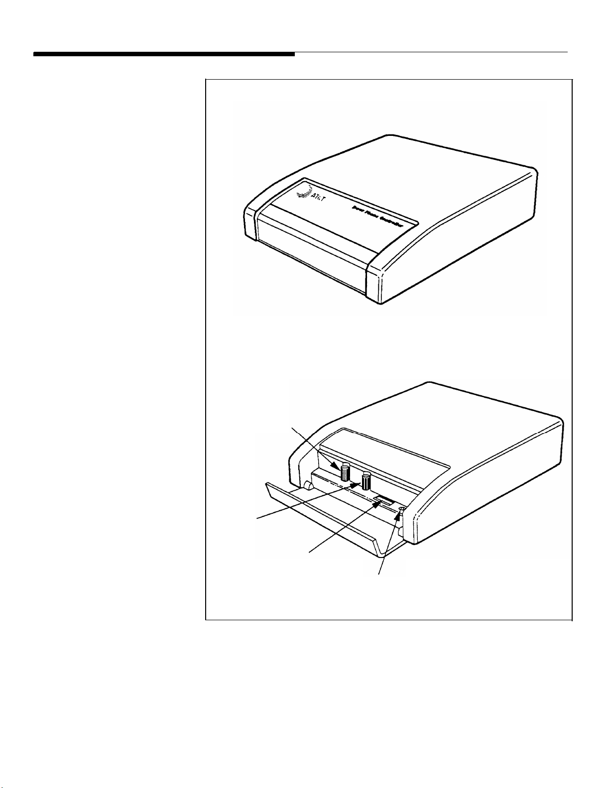
SPEAKER
VOLUME
TALK BACK
VOLUME
DIP SWITCH
LED
Figure 1-1. Front View of the AT&T Door Phone
Controller and Control Panel
1-4 Introduction
Page 16

Terms You Should Know
AuxiliaryAlert
bell/chime within the building.
Cadence —Telephone Ringing cycle, i.e., 2 second ringing,
4 second no ringing.
C.O. line —Central Office telephone line carrier into building.
EKTS (Electronic Key Telephone System) —Small business
telephone communications system.
Ground Start —One method by which a business telephone
system (PBX) signals the telephone company that you have
gone off-hook. Used in most business applications – contact
your telephone company to determine if you have Ground or
Loop Start.
Loop Start —One method of signaling the telephone company
that your telephone has gone off-hook – used for most
residential and communication system applications. Contact
your telephone company to determine if you have Ground or
Loop Start.
—A door speaker’s push button can activate a
PBX (Private Branch Exchange) —Business telephone
system.
Ringdown
speaker’s push button will cause the AT&T Door Phone
Controller to dial the number of a predetermined telephone
station number (PBX or EKTS must be installed). When the
telephone is answered, there is direct two-way communication
with the door speaker.
Trunk Port —PBX connection for Central Office or trunk lines.
Station Port —PBX connection for station sets.
Hook-Flash —This causes telephone equipment to go “on
hook” for a duration usually less than a second (not long
enough to be considered as calling for the circuit to be
released.)
—In Station mode, the activation of the door
Introduction 1-5
Page 17

Installation Procedures
2
Installation Procedures 2-1
Page 18

2-2 Installation Procedures
Page 19

Important Safety Instructions
When using your telephone equipment, basic safety
precautions should always be followed to reduce the risk of fire,
electric shock and injury to persons, including the following:
Read and understand all instructions.
1.
2.
Follow all warnings and instructions marked on the
product.
3.
Unplug this product from the wall outlet before cleaning.
Do not use liquid cleaners or aerosol cleaners. Use a
damp cloth for cleaning.
4.
Do not use this product near water, for example, near a
bath tub, wash bowl, kitchen sink, or laundry tub, in a
wet basement, or near a swimming pool.
5.
Do not place this product on an unstable cart, stand, or
table. The product may fall, causing serious damage to
the product.
6.
Slots and openings in the cabinet and the back or bottom are provided for ventilation. To avoid overheating,
these openings must not be blocked or covered. The
openings should never be blocked by placing the
product on the bed, sofa, rug, or other similar surface.
This product should never be placed near or over a
radiator or heat register. This product should not be
placed in a built-in installation unless proper ventilation
is provided.
This product should be operated only from the type of
7.
power source indicated on the marking label. If you are
not sure of the type of power supply to your home, con-
sult your dealer or local power company.
Installation Procedures 2-3
Page 20

8.
9. Do not allow anything to rest on the power cord. Do not
10. Do not overload wall outlets and extension cords as this
WARNING: RISK OF ELECTRICAL SHOCK –
EQUIPMENT MUST BE PROPERLY GROUNDED.
Your AT&T equipment requires a properly grounded
three-prong power receptacle for safe operation. Have
the receptacle checked by a qualified electrician before
connecting this equipment. Do not cut or remove the
third (ground) prong from the power transformer. Do
not use two-prong extension cords or adapters to
defeat the safety features of this equipment. If you
have a two-prong receptacle, it must be replaced with
a three-prong receptacle, installed by a qualified
electrician.
locate this product where the cord will be abused by persons walking on it.
can result in the risk of fire or electric shock.
11.
12. To reduce the risk of electric shock, do not disassemble
13. Unplug this product from the wall outlet and refer servic-
Never push objects of any kind into this product through
cabinet slots as they may touch dangerous voltage
points or short out parts that could result in a risk of fire
or electric shock. Never spill liquid of any kind on the
product.
this product, but take it to a qualified serviceman when
some service or repair work is required. Opening or
removing covers may expose you to dangerous voltages
or other risks. Incorrect reassembly can cause electric
shock when the appliance is subsequently used.
ing to qualified service personnel under the following
conditions:
A. When the power supply cord or plug is damaged or
frayed.
2-4 Installation Procedures
B. If liquid has been spilled into the product.
Page 21

C. If the product has been exposed to rain or water.
D. If the product does not operate normally by following
the operating instructions. Adjust only those controls
that are covered by the operating instructions, because
improper adjustment of other controls may result in
damage and will often require extensive work by a
qualified technician to restore the product to normal
operation.
E. If the product has been dropped or the cabinet has
been damaged.
F. If the product exhibits a distinct change in performance.
14.
15.
SAVE THESE INSTRUCTIONS.
General Information
Please adhere to the following precautions:
1. Never install telephone wiring during a lightning storm.
2. Never install telephone jacks in wet locations unless the
3. Never touch uninsulated telephone wires or terminals un-
Avoid using a telephone (other than a cordless type)
during an electrical storm. There may be a remote risk
of electric shock from lightning.
Do not use the telephone to report a gas leak in the
vicinity of the leak.
jack is specifically designed for wet locations.
less the telephone line has been disconnected at the
network interface.
4. Use caution when installing or modifying telephone lines.
Installation Procedures 2-5
Page 22

Introduction
Contact a licensed electrician
for installation of optional
devices such as an electric
strike plate and auxiliary alert
device which may require
electrical wiring. For the electric
strikeplate, a low voltage device
(24 volts or less) is
recommended.
This section provides instructions for installing your AT&T Door
Phone Controller. Provided are installation instructions for an
optional electric door strike plate, door ajar contacts, and an
auxiliary alert device. These optional components must be
installed prior to the installation of your AT&T Door Phone
Controller. (Refer to the respective installation manuals for
specific mounting and wiring instructions.) The flow-chart
provided in Figure 2-9, will help direct you to the next
appropriate section for attaching the AT&T Door Phone
Controller to the telephone equipment in your home or
business (also see Compatibility Chart on page iii).
Inside the AT&T Door Phone Controller shipping carton
you will find:
■ The AT&T Door Phone Controller unit
■ Mounting template (along the edge of the Tear-out
Reference Card)
■ Power cord and attached transformer
■ Two mounting screws
■ Two 6-conductor modular-to-modular 6 foot long cables
■ Terminal strip connector
■ Instruction Manual (this manual)
Door Phone Controller Back Panel Connections
The 14-contact terminal strip
can be unplugged from the back
panel.
The AT&T Door Phone Controller back panel (see Figure 2-1)
has two RJ11 modular connectors and one 14-contact “hard
wire” terminal strip. These connections provide:
■ Auxiliary Alert Contacts (2) – output to optional door
bell/chime device.
■ Door Latch Contacts (3) – output to an electric door strike.
2-6 Installation Procedures
■ Remote Open Button Contacts (2) – input from a remote
(inside) door open button.
Page 23

■ Door Ajar Switch Contacts (2) – input from door ajar device.
■ Door Bell Button Contacts (2) – input from door bell/chime
button.
■ Shield Contact (1) – used for shielding audio speaker wires.
■ Speaker Contacts (2) – provides audio connection to door
speaker(s).
Host system RJ11 (J1 Host) modular jack interface —This
jack is provided for connection to your own telephone set, or
business telephone system (PBX or EKTS) (the host system).
Central Office RJ11 (J2) modular jack interface —This jack is
provided for connection to a C.O. telephone line (from
telephone company’s central office).
WARNING: RISK OF ELECTRICAL SHOCK —
EQUIPMENT MUST BE PROPERLY GROUNDED.
Your AT&T equipment requires a properly grounded
three-prong power receptacle for safe operation. Have
the receptacle checked by a qualified electrician before
connecting this equipment. Do not cut or remove the
third (ground) prong from the power transformer. Do
not use two-prong extension cords or adapters to
defeat the safety features of this equipment. If you
have a two-prong receptacle, it must be replaced with
a three-prong receptacle, installed by a qualified
electrician.
Installation Procedures 2-7
Page 24
AT&T DOOR PHONE
CONTROLLER
BACK PANEL
RJ11
CONNECTORS
14-POSITION
TERMINAL STRIP
(REMOVABLE)
Figure 2-1. Door Phone Controller Back Panel Connections
Prior To Installation
NOTE: Consider
1.
Never install
2.
Never install
jack is specifically designed for wet
3.
Never touch uninsulated telephone wires or terminals unless the telephone
network interface.
the following items before installation:
telephone wiring during a lightning storm.
telephone jacks in wet
line has been disconnected at the
locations unless the
locations.
2-8 Installation Procedures
4.
Use caution when
installing or modifying
telephone lines.
Page 25

AT&T Door Phone Controller Location
You need to determine exactly where you want the unit
installed and how you want it configured. Another consideration
is what components will be used with the AT&T Door Phone
Controller. Here are some questions that must be answered
prior to installation:
■ Do you currently have a door speaker installed?
■ Do you have a business telephone system (PBX or EKTS)?
■ Do you have a remote door unlock mechanism (electric
door strike) installed?
■ Do you have an auxiliary alert system (door chime) currently
installed?
■ Do you have a door ajar switch installed?
The AT&T Door Phone Controller is designed to control the
functions of the components mentioned above, and how you
answer these questions will determine how the AT&T Door
Phone Controller will be installed, optioned, and operated.
When selecting options for your AT&T Door Phone Controller,
e.g., to change the door-unlock security code, the AT&T Door
Phone Controller unit must be DIP switch selected to Option
Selection mode. For this reason you may want to install the
AT&T Door Phone Controller unit in a secure area which has
access only by authorized personnel. If you are installing the
unit in a business environment (currently have PBX/EKTS), you
may wish to install the unit along with the telephone equipment.
(See Figure 2-2 for a typical installation diagram.)
Installation Procedures 2-9
Page 26
AT&T DOOR PHONE
CONTROLLER
(Secure Location)
22-24 GAUGE
WIRE
AUX. ALERT DEVICE
TELEPHONE
EXTENSION
22-24 GAUGE
WIRE
DOOR AJAR
SWITCH
MODULAR
PHONE
CABLE
TELEPHONE
EQUIP.
22-24 GAUGE
WIRE
EXISTING
PHONE
LINES
SHIELDED TWISTED
PAIR SPEAKER
WIRES
ATTENDENT
POSITION
DOOR SPEAKER
W/ PUSH BUTTON
ELECTRIC
DOOR STRIKE
PLATE DEVICE
Figure 2-2. Typical AT&T Door Phone Controller Installation
2-10 Installation Procedures
Page 27

Installation
Mounting Instructions
The AT&T Door Phone Controller can be placed on a flat table
or shelf, or mounted to a wall.
Wall Mount Instructions
The AT&T Door Phone Controller is shipped with a keyhole
mounting template and mounting screws. Follow the steps
below to mount the Door Phone Controller to a wall.
When moving AT&T Door
Phone Controller or adding/
removing cables from back
panel, unplug transformer from
120V outlet.
Also unplug the terminal strip
and modular phone connectors
on the back panel.
1.
Place template (tear-out page at end of manual) over
desired wall mounting location and mark screw positions.
2. Use a Philips screwdriver to screw each of the two
screws into the marked screw positions.
IMPORTANT: Do not drive screws all the way into
wall; adequate space (5/16'') must be left to position
the AT&T Door Phone Controller bottom panel
keyholes over screw heads.
3. Mount the AT&T Door Phone Controller over the protruding screw heads and seat unit firmly to the wall. See
Figure 2-3.
WARNING: RISK OF ELECTRICAL SHOCK —
EQUIPMENT MUST BE PROPERLY GROUNDED.
Your AT&T equipment requires a properly grounded
three-prong power receptacle for safe operation. Have
the receptacle checked by a qualified electrician before
connecting this equipment. Do not cut or remove the
third (ground) prong from the power transformer. Do
not use two-prong extension cords or adapters to
defeat the safety features of this equipment. If you
have a two-prong receptacle, it must be replaced with
a three-prong receptacle, installed by a qualified
electrician.
Installation Procedures 2-11
Page 28

4. When the AT&T Door Phone Controller is securely
mounted to the wall, then all cables and wires can be
connected to the terminal strip and then plugged into
the back panel.
DOOR PHONE
CONTROLLER
BACK PANEL
KEYHOLE
MOUNTING
SLOTS
5/16'' TYPICAL
8.1''
MOUNTING SCREWS
Figure 2-3. Mounting AT&T Door Phone Controller to
Wall
2-12 Installation Procedures
Page 29

Connecting Door Speaker, Door Button, and Door
Ajar Switch to the AT&T Door Phone Controller
Use the diagram in Figure 2-4 and follow the steps below:
Polarity of wires is not important.
Total wire length should not
exceed 1500 feet.
Door Ajar switch should be
closed when door is closed. If a
door ajar switch will not be
used, you must leave a jumper
installed across the two “Door
Ajar Switch” terminals.
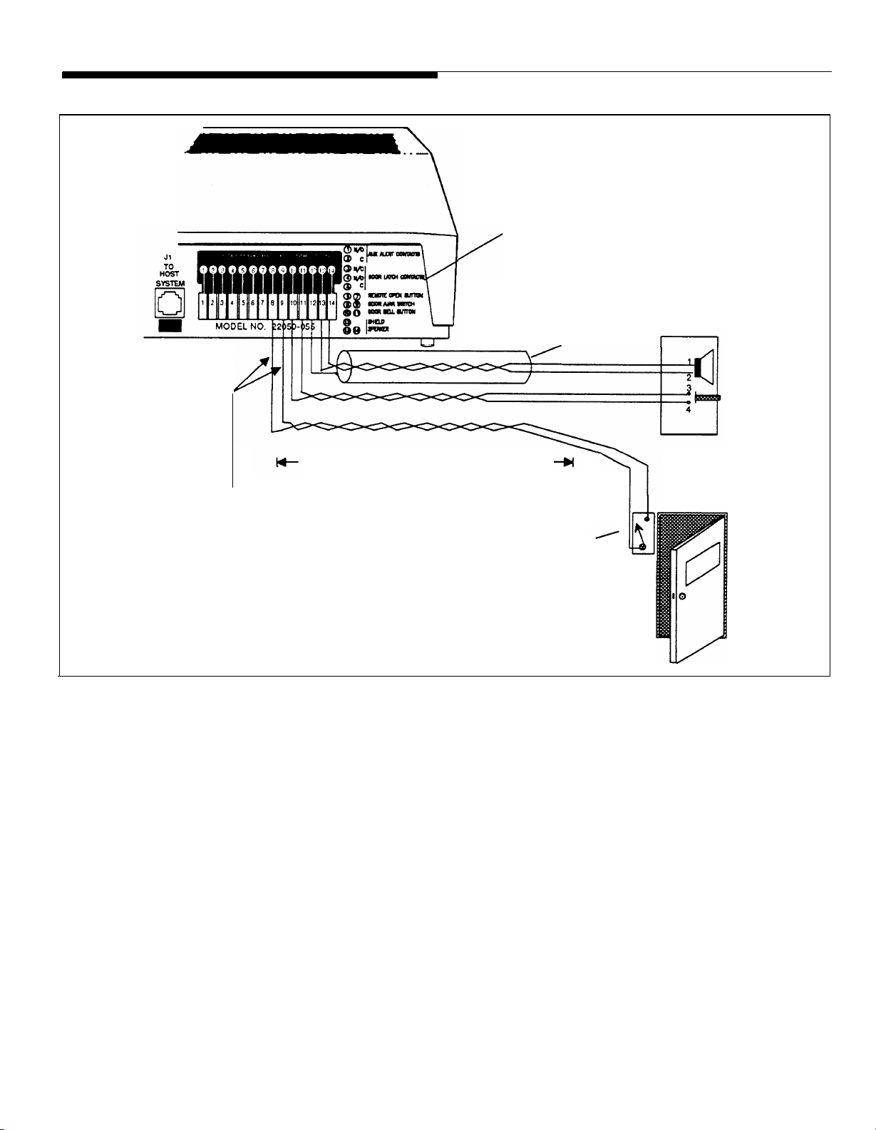
1.
Run shielded twisted pair wires (22–24AWG) from the
“Speaker” terminals on the rear panel of the AT&T Door
Phone Controller (13 & 14) to the installed Door
Speaker (1 & 2). Connect the shield to the “Shield” terminal on the controller (12).
Run 2 wires (22–24AWG) from the “Door Bell Button”
2.
terminals (10 & 11) to the door bell push button on the
installed door speaker/push button assembly (3 & 4).
Run 2 wires (22-24AWG) from the optional “Door Ajar
3.
Switch” terminals (8 & 9) to the installed door ajar
switch.
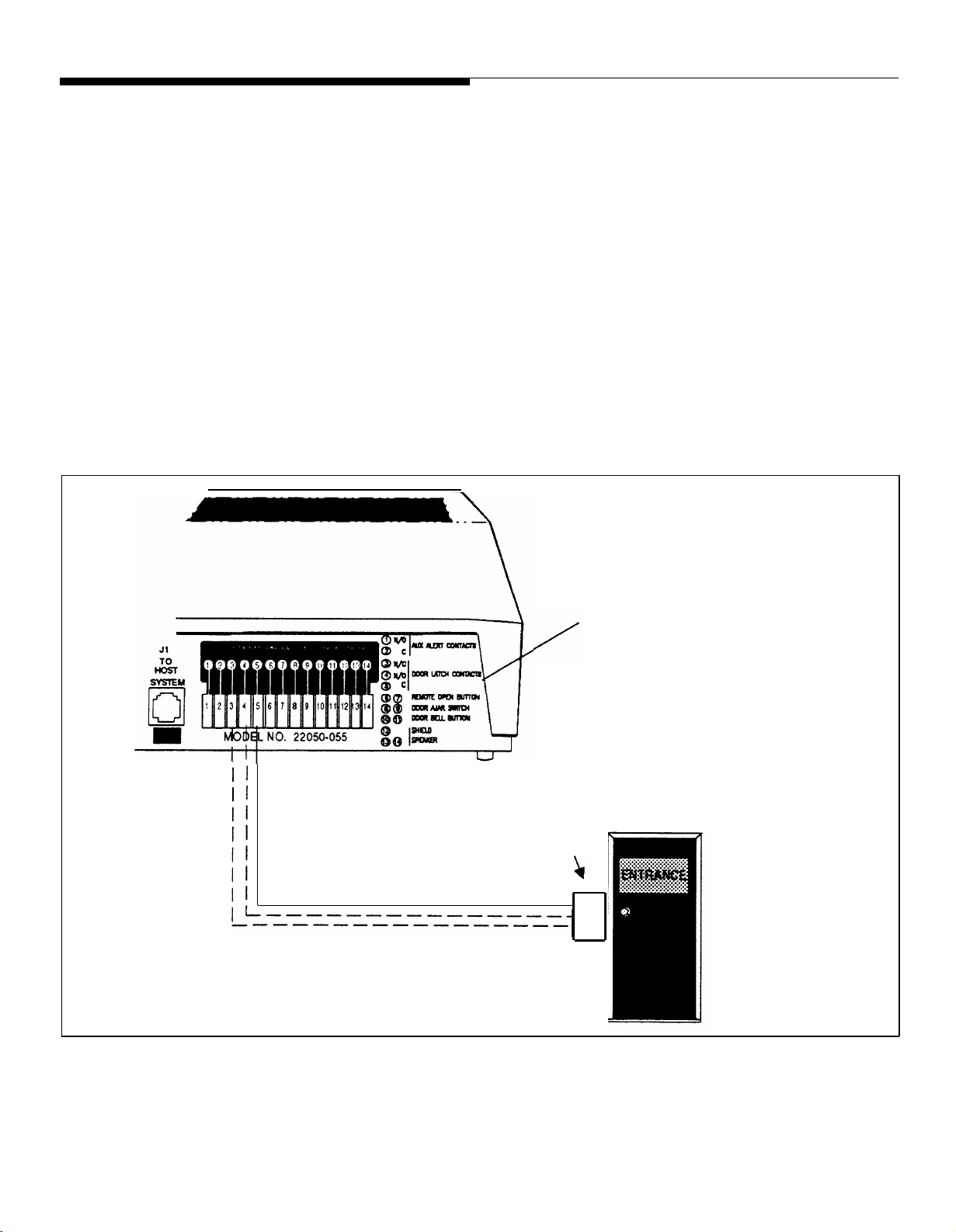
Remote Door Open Switch (optional)
A remote door open switch (normally-open contact) provides
additional means for opening an electric door opening device.
To connect wires for a remote door open switch use the
diagram in Figure 2-5 and follow the steps below.
1. Install the remote door open button in desired location
using manufacturer’s installation instructions.
2. Run 2 wires (22–24AWG) from the installed (normallyopen contact) remote door open switch to the “Remote
Door Open” terminals (6 & 7) on the AT&T Door Phone
Controller back panel (polarity of wires is not important).
Installation Procedures 2-13
Page 30
SHIELDED, TWISTED PAIR, 24 AWG.
APPROX. 1500 FT. MAXIMUM LENGTH
JUMPER THE TWO DOOR AJAR SWITCH TERMINALS
IF DOOR AJAR DEVICE IS NOT USED
DOOR AJAR SWITCH
NOTE: MAGNETIC SWITCH
IS CLOSED WHEN DOOR
IS CLOSED
AT&T DOOR PHONE CONTROLLER
BACK PANEL
AT&T DOOR SPEAKER
AND DOOR BELL
BUTTON
Figure 2-4. Connections for AT&T Door Phone Speaker, Door Button and Door
Ajar Devices
2-14 Installation Procedures
Page 31

AT&T DOOR PHONE
CONTROLLER BACK PANEL
Figure 2-5. Connections for Remote Door Open Switch (optional)
MOMENTARY
PUSH BUTTON
NORMALLY OPEN
Electric Door Strike Plate Device (optional)
An electric door strike plate is used to automatically open a
closed or locked door. A low-voltage device (24V or less) is
If your Electric Door Strike Plate
has more than a 1 Amp current
draw, then an external relay
arrangement is required.
recommended. The AT&T Door Phone Controller can provide
an open or closed contact when requested to interface to and
to operate your electric door strike plate device. Once an
electric door strike plate has been installed, it can be controlled
by the AT&T Door Phone Controller unit, either from entering
the appropriate digits from a touch tone phone or from the
Remote Open switch (push button).
Follow the
door strike
steps below and refer to Figure 2-6 for wiring the
plate device to the AT&T Door Phone Controller.
Installation Procedures 2-15
Page 32
Do not include strike plate wires
within the same cable as others
wires connecting to the AT&T
Door Phone Controller.
1.2.Have the electric door strike pIate device installed as instructed by the manufacturers installation manual.
Check electric installation codes and local ordinances
for exact wiring requirements in your area.
Normally Open (N.O.), Normally Closed (N.C.), and
Common (C.) relay contacts are accessible at the Door
Phone Controller terminal block. Wire these to the door
strike plate device and its power source as instructed by
your manufacturer’s installation manual. If no instructions exist, wire the above relay contacts to the existing
door open button (see #3 below).
AT&T DOOR PHONE
CONTROLLER BACK PANEL
ELECTRIC
DOOR STRIKE
PLATE DEVICE
WITH POWER
SOURCE
Figure 2-6. Connections for Electric Door Strike Plate (optional)
2-16 Installation Procedures
Page 33

NOTE: One or the other will
apply, not both.
3. Verify all connections when connecting the door strike
contacts on the AT&T Door Phone Controller to existing
door open buttons. Make sure of the following:
■
The NO and C contacts are connected in parallel to a
normally-open button.
■
The NC and C contacts are connected in series to a
normally-closed button.
Auxiliary Alert Device
In most configurations, the Door Phone Controller will cause a
telephone to ring when the doorbell button is pushed. An aux-
iliary alert device (chime, bell, horn, tone generator, etc.) can
also be used as an alert to notify the person inside the building
that the doorbell button has been pushed (Auxiliary Alert
If the Auxiliary Alert Device has
more than a 1 Amp draw, then
an external relay arrangement
will be required.
See Appendix E for specific
auxiliary alert device installation
information.
Mode). A low-voltage device (24V or less) is recommended.
Follow the steps below (refer to Figure 2-7) for wiring auxiliary
alert device (door bell/chime) to the Door Phone Controller:
1.
2. The Normally Open (N.O.) and Common (C.) relay con-
(optional)
Install the auxiliary alert device (door bell/chime) as in-
structed by the manufacturer’s installation manual.
tact, located on the Door Phone Controller back panel
(see Figure 2-7), are accessible at the Door Phone Controller terminal block. Wire these to the auxiliary alert
device and it’s power source as instructed by the
manufacturer’s installation manual.
Connecting Power
When the Door Phone Controller has been mounted to a wall
or placed on a shelf and all cables and wires have been
connected to the back panel, plug the transformer into a 120
VAC outlet. See Figure 2-8.
Installation Procedures 2-17
Page 34

AT&T DOOR PHONE
CONTROLLER BACK PANEL
DOOR BELL/CHIME
(AUXILIARY ALERT
DEVICE) WITH POWER
SOURCE
Figure 2-7. Connections for Auxiliary Alert Device (optional)
2-18 Installation Procedures
Page 35

Figure 2-8. Plug the AT&T Door Phone Controller Power
Cord and Transformer to 120 VAC Outlet
Installation Procedures 2-19
Page 36

Operation and Controls Information
Door Ajar Function
Default Condition —After the door has been opened by the
four digit code or the remote push button, the Door Phone
Controller will wait for the Door Ajar Call-back time-out to
elapse. At this point if the door is still open, the Door Phone
Controller will call back the phone/chime for the duration of the
ring/chime duration and then repeat after the Door Ajar
Call-back time-out has elapsed again. If the phone is answered
during that time, a Door Ajar Tone will be heard. The Door Ajar
Tone will cease when any DTMF Digit is pressed, or the user
speaks or hangs-up.
Alternate Condition —If the door is ever opened and the Door
Ajar Call-back time-out has elapsed, the Door Phone Controller
will call back the phone/chime for the duration of the ring/chime
duration and then repeat after the Door Ajar Call-back time-out
has elapsed again. If the phone is answered during that time, a
Door Ajar Tone will be heard. The Door Ajar Tone will cease
when any DTMF digit is pressed, or the user speaks or
hangs-up.
Speaker Volume Control
You can adjust the volume level of the door speaker by
adjusting the Speaker Volume Control on the Door Phone
Controller front panel (see Figure 1-1).
Talk Back Volume Control
You can adjust the volume level from the door speaker to an
inside telephone extension by adjusting the Talk Back Volume
Control (see Figure 1-1).
2-20 Installation Procedures
Page 37

LED
When the AT&T Door Phone Controller is powered on and
functioning normally, the LED (Figure 1-1) should continually
blink 2.5 times a second. If there is a malfunction the LED will
blink faster than 4 times a second (see Troubleshooting
section) or go out completely. If the LED is not lit, check power
to unit first before calling for repair.
Installation Procedures 2-21
Page 38

Connecting the AT&T Door Phone Controller to
Your Telephone Equipment
Use the flow chart in Figure 2-9 to assist in configuring the
AT&T Door Phone Controller to your residential or
business-type telephone equipment. Answer each appropriate
question in the flow chart and refer to the section specified
within this manual. Then proceed with the necessary
installation and option selection requirements. NOTE: If you
are installing the AT&T Door Phone Controller into a
typical Home/Residential environment (no PBX) refer to
Section 3 now.
REFER TO
SECTION 3
NO
RESIDENTIAL INSTALLATION
Do
you have a
Business
Telephone
System
?
YES
YES
Spare
Trunk Port
Available*
?
NO
*You must refer to your telephone system
owner manual for description of this
port.
YES
Spare
Station Port
Available*
?
NO
REFER TO
SECTION 4
PBX WITH DEDICATED
TRUNK PORT
REFER TO
SECTION 5
PBX WITH STATION PORT
REFER TO
SECTION 6
PBX WITHOUT DEDICATED
TRUNK OR STATION PORT
Figure 2-9. Configuration of Telephone Equipment Flow Chart
2-22 Installation Procedures
Page 39

Installation for Home/Residential
(Trunk Saver Mode - Loop Start)
3
Installation
— Home/Residential 3-1
Page 40

Overview
This section provides installation and operation information for
applications such as residences or small businesses which do
not have a telephone system.
You may also use the AT&T
Door Phone Controller with a
dedicated phone.
When your AT&T Door Phone Controller is installed with
standard telephone equipment (no PBX), the unit may operate
in Shared Line Mode which permits a single telephone set to
be shared between the AT&T Door Phone Controller and an
outside line (to a Central Office). Thus, the standard telephone
equipment can be used for normal call operations as well as
servicing the door.
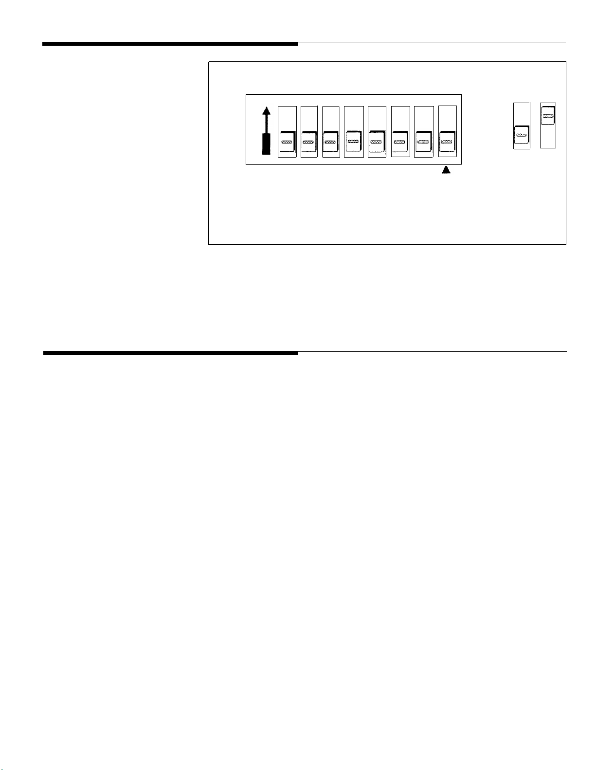
DIP Switch Selections
To customize the AT&T Door Phone Controller to your specific
installation and option requirements, you must properly set the
8 position DIP switch located on the AT&T Door Phone
Controller front panel (see Figure 1-1).
CAUTION: Do not connect to the modular jacks on
the AT&T Door Phone Controller until after the DIP
switches have been properly set.
Complete information about the
DIP switch settings can be
found in Appendix A.
3-2 Installation —
Home/Residential
When using the Door Phone Controller with a small business or
residential telephone equipment (no PBX installed), the DIP
switches must be set as shown in Figure 3-1 (all OFF).
Page 41
ON
1 2 3 4 5 6 7 8
LEGEND
Off On
Installation
When moving the Door Phone
Controller or adding or removing
cables from the back panel,
unplug the transformer from
120V outlet. Also unplug the
terminal strip and modular
phone connectors on the back
panel.
NOTE: The Forced Disconnect
Timeout option does not apply
when DIP switch position 8 is ON.
Figure 3-1 Home/Residential DIP Switch Settings
.
I
I
— —
ON for
Option Selection
Mode Only
Connect the Door Phone Controller using the information in
Section 2. Refer to Figure 3-2.
Installation — Home/Residential 3-3
Page 42

AT&T DOOR PHONE CONTROLLER
BACK PANEL
TO DOOR SPEAKER
TO DOORBELL BUTTON
TO DOOR AJAR SWITCH
TO REMOTE DOOR OPEN SWITCH
TO DOOR STRIKE PLATE DEVICE
TO C.O.
(Outside Line)
TO AUXILIARY ALERT DEVICE (DOOR BELL/CHIME)
TO TELEPHONES
Figure 3-2. Connecting AT&T Door Phone Controller to Standard Telephone
Equipment
OPTIONAL
3-4 Installation — Home/Residential
Page 43

Option Selection
Refer to Appendix B for a
detailed explanation of each of
these options.
The final step of the installation procedure is selecting options
for your AT&T Door Phone Controller. The selection of these
options must be done while in the Option Selection Mode. This
mode lets you control such things as:
■
Delay Before Door Ajar Call-Back
■
Ring/Chime Cadence
■
Ring/Chime Duration
■
Door Unlock Code
■
Door Unlock Duration
■
Enable Door Code
■
Door Ajar Mode
■
Forced Disconnect
Time-Out
Any or all options may be
reselected in any order.
■
Reset Options to Factory Defaults
Follow the steps below to select options for the Door Phone
Controller.
1.
Select Option Selection Mode by setting position 8
of the Door Phone Controller DIP switch to the ON
position (see Figure 1-1).
2. Once the DIP switch has been set, you must make connection to the door speaker by “hook-flashing” the
phone (within 5 seconds) and entering “##3” on the
telephone keypad (option selection mode is active as
soon as you hear a distinctive dial tone).
3. Use Table 3-1 to make each option selection.
Installation — Home/Residential 3-5
Page 44

Table 3-1. AT&T Door Phone Controller Option Selection Information
Options
Delay Before
Verify
To Select Option
Press
00
Door Ajar
Mode Option/
Call-back
Ring/Chime
To Verify
To Select Option 10
01
Cadence
To Verify
11
Ring/Chime To Select Option 20
Duration
Door Unlock
To Verify
To Select Option 30
21
Code
To Verify
31
Listen
Press
Single 000 to 255 for 0 to 255 Double
Beep seconds of delay after strike Beep
plate release stops until
AT&T Door Phone Controller
calls back to indicate that
door is ajar
Single 24 (for 2 sec. on 4 sec. off
Beep cadence)
15 (for 1 sec. on 5 sec. off
cadence)
Single 00 to 99 (0 to 99 second(s)
Beep
Single 4 digits (first digit must be
Beep 0,3,4,5,6,7 or 8
ring/chime)
remaining digits can be set
from 0 to 9)
or
Listen
For
Double
Beep 4 sec.
Double
Beep
Double 6736
Beep
Default
30 sec.
2 sec./
30 sec.
“OPEN”
Door Unlock
Duration
Enable Door
Code
Door Ajar To Select Option 50
Mode
Forced
Disconnect
Time-Out
Reset Options
to Factory
Defaults
NOTE: The Door Ajar Delay (Option Selection) will begin when the call to the door speaker is disconnected.
To Select Option 40
To Verify
To Select Option 50
To Verify
To Verify
To Select Option 60
To Verify
To Select Option 70
To Verify
41
51
51
61
71
Single 00 to 99 (door lock active
Beep time in sec.)
Single
Beep 0 Disable door code
Single 2 For callback after strike
Beep
Single 010 to 255 (unit disconnects
Beep
Single ## (to restore factory default
Beep
1
Enable door code Double
plate release only
3 For callback anytime
door is opened
in 10 to 255 sec.)
conditions)
.
Double 4 sec.
Beep
Beep
Double 2
Beep
Double 120 sec.
Beep
Double
Beep
1
(Enabled)
N/A
3-6 Installation —
Home/Residential
Page 45

The Forced Disconnect
Time-out option does not apply
when setting options (unless 2
minutes elapse without a
Touch-Tone selection)
4. To exit option selection mode, press “##3” on the
telephone keypad (you will hear 2 beeps). Hang up the
phone.
5. Set position 8 of the AT&T Door
switch back to the OFF position.
Phone Controller DIP
Operation –
Basic Door Answer Function
Visitor Presses Door Speaker Button
When a visitor presses the door speaker push button, the
AT&T Door Phone Controller will signal the telephone
equipment inside your home or building to ring, and activate a
door-bell/chime device (optional). Any additional presses on the
door speaker push button will be ignored until the option
selected ring/chime duration has expired (with the exception
that a confirmation tone will still be sent to the speaker when
the door button is pressed).
Answering a Call from the Door Speaker
The person inside the building can simply answer the ringing
phone and establish two-way communications with the door
speaker. To open the door, the person inside the building either
enters the Door Code on the telephone’s keypad or presses
the customer provided door-unlock push button. Either of these
actions will activate the customer provided electric door strike
plate device.
Installation —
Home/Residential 3-7
Page 46

As an alternative response when the telephone or door
bell/chime is heard, the person inside the building can press
the door-unlock push button, which will stop the ringing and will
open the door. This allows the door to be unlatched without the
use of a phone.
Calling the Door Speaker from Inside the Building
To initiate a call to the door, the person within the building
simply takes the telephone off-hook and hook-flashes the
telephone within the first 4 seconds. At this point, there will be
direct two-way communication from within the building to the
door speaker.
Telephone Line In Use When Visitor Presses Door Speaker Button
Once the push button is
pressed, you can “Hook Flash”
to the door speaker and then
back to the original call only
once, unless the push button is
pressed again.
If you forget to hook-flash back
to the original call, the AT&T
Door Phone Controller will call
you back.
If a visitor presses the door speaker button while an existing
call is already taking place on the C.O. line, the AT&T Door
Phone Controller will generate a “door alert” signal to indicate
a visitor needs attention at the entrance. The person inside the
building can hook-flash the phone and be in direct two-way
communication to the door speaker. Then normal AT&T Door
Phone Controller functions can take place. When door phone
functions have been completed, i.e., door has been remotely
opened, hook-flashing the phone again within the forced
disconnect timeout (or pressing 9) will return the line back to
the original call. This feature operates much like a call-waiting
function.
3-8 Installation — Home/Residential
Page 47

Telephone Line In Use With Door When Incoming Call Arrives
If there is a call in progress between the door speaker and a
person inside the building and a C.O. call comes in, the person
inside the building (not the door speaker) will hear a call
waiting tone. The person inside the building can hook-flash the
phone (or dial 9) and communicate with the incoming caller.
When the call is complete, the person inside the building hangs
up the phone or to speak with the person at the door speaker
again, the person inside the building must hook-flash the phone
(within 4 seconds after picking up the receiver).
Installation —
Home/Residential 3-9
Page 48

Installation for Telephone System With
Available Dedicated Trunk Port
4
Installation - Dedicated Trunk Port 4-1
Page 49

Overview
This section provides installation and operation information for
installations with a telephone system that has an available
Dedicated Trunk port.
DIP Switch Selections
Complete information about the To customize the AT&T Door Phone Controller to your specific
DIP switch settings can be
found in Appendix A.
installation and option requirements, you must properly set the
8-position DIP switch located on the AT&T Door Phone
Controller front Panel (see Figure 4-1).
CAUTION: Do not connect to the modular jacks on the
AT&T Door Phone Controller until after the DIP switches
have been properly set.
Use the Flow Chart in Figure
4-1 to properly set the DIP
switch.
When using the AT&T Door Phone Controller with a telephone
system which has an available dedicated trunk, set the DIP
switch as shown in Figure 4-1.
you must know if the dedicated trunk is Loop Start or Ground
Start; this information can be obtained from your local
telephone company.
Prior to setting this DIP switch,
4-2 Installation - Dedicated Trunk Port
Page 50

LEGEND
Off On
. . . The C.O.
(Trunk Saver Mode)
Immediately
after cut-thru
(Dialing Trunk) to AT&T
Door Phone Controller,
what do you want to
be connected
to...?
.
. . The DOOR
(Port Saver Mode)
LOOP START
LOOP START
1 2 3 4 5 6 7 8
ON
ON for
Option Selection
Mode Only
1 2 3 4 5 6 7 8
ON
Figure 4-1. DIP Switch Setting for PBX with Dedicated Trunk Port
Installation
When moving the AT&T Door
Phone Controller or adding or
removing cables from the back
panel, unplug transformer from
120V outlet. Also unplug the
terminal strip and modular
cords.
Complete information regarding
each DIP switch position can be
found in Appendix A.
To customize the AT&T Door Phone Controller use the
information supplied in Section 2 and the diagram in Figure
4-2a. For ground start installations, also see Figure 4-2b.
phone connectors on the back panel.
Install the AT&T Door Phone Controller using the information
supplied in Section 2 and the diagram in Figure 4-2a. For
ground start installations, also see Figure 4-2b.
Installation - Dedicated Trunk Port 4-3
Page 51

AT&T DOOR PHONE
CONTROLLER BACK PANEL
TERMINAL BLOCK “HARD
WIRE” CONNECTOR
NOT USED
NOTE: For Ground Start installations
see Figure 4-2b.
TO DOOR SPEAKER
TO DOOR BELL BUTTON
TO DOOR AJAR SWITCH
TO REMOTE DOOR OPEN SWITCH
TO DOOR STRIKE PLATE DEVICE
TO AUXILIARY ALERT DEVICE (DOOR BELL/CHIME)
TRUNK PORT
TO C.O.
TO C.O. TRUNK PORT
TRUNK PORT
OPTIONAL
TELEPHONE SYSTEM
STATION
PORT
STATION
PORT
Figure 4-2a. Connecting Door Phone Controller to Standard Telephone Equipment
4-4 Installation - Dedicated Trunk Port
Page 52

TO AT&T DOOR PHONE CONTROLLER
J1 CONNECTORS
TO C.O.
TO “SHIELD” TERMINAL (12) ON AT&T
DOOR PHO
NE CONTROLLER
TELEPHONE SYSTEM
GROUND TERMINAL
TRUNK PORT STATION
PORT
TRUNK PORT
NOTE: For Ground Start installations:
Connect the green wire to Tip
and the red wire to Ring.
Figure 4-2b. Ground Start Installations
TRUNK PORT
STATION
PORT
TELEPHONE SYSTEM
Installation - Dedicated Trunk Port 4-5
Page 53

Option Selection
Refer to Appendix B for a
detailed explanation of each of
these options.
The final step of the installation procedure is selecting options
for your AT&T Door Phone Controller. The selection of these
options must be done while in the Option Selection Mode. This
mode lets you control such things as:
■
Delay Before Door Ajar Call-Back
■
Ring/Chime Cadence
■
Ring/Chime Duration
■
Door Unlock Code
■
Door Unlock Duration
■
Enable Door Code
■
Door Ajar Mode
■
Forced Disconnect Time-Out
■
Reset Options to Factory Defaults
4-6 Installation - Dedicated Trunk Port
Page 54

Follow the steps below to select options for your AT&T Door
Phone Controller.
CAUTION: Never connect an AT&T DOOR PHONE
CONTROLLER with the DIP Switches optioned for TRUNK
access to a STATION LINE! Doing so may cause damage
to the STATION LINE and/or the AT&T DOOR PHONE
CONTROLLER!
1.
Select Option Selection Mode by setting position 8
of the AT&T Door Phone Controller DIP switch to
the ON position (see Figure 1-1).
2.
Once the DIP switch has been set, you must make connection to the door speaker by accessing the trunk
connected to the AT&T Door Phone Controller. At this
point you must enter “##3” on the telephone keypad (option selection mode is active as soon as you hear a
distinctive dial tone).
Any or all options may be
reselected in any order,
The Forced Disconnect
Time-out option does not apply
when setting options (unless 2
minutes elapse without a
Touch-Tone selection).
3.
Use Table 4-1 to make each option selection.
4.
To exit option selection mode, press “##3” on the
telephone keypad, you will
hear 2 beeps. Hang up the
phone.
5.
Set position 8 of the AT&T
switch (Figure 1-1) back to
Door Phone Controller DIP
the OFF position.
Installation - Dedicated Trunk Port 4-7
Page 55

Operation –
Basic Door Answer Function
Table 4-1. AT&T Door Phone Controller Option Selection Information
Options
Mode Option/
Verify
Delay Before To Select Option
Door Ajar
Call-back
To Verify
Ring/Chime To Select Option
Cadence
To Verify
Ring/Chime To Select Option
Duration
To Verify
Door Unlock To Select Option
Code
To Verify
Press
00
01
10
20
21
30
31 remaining digits can be set
Listen
For
Single 000 to 255 for 0 to 255
Beep seconds of delay after strike
plate release stops until
AT&T Door Phone Controller
calls back to indicate that
door is ajar
Single 24 (for 2 sec. on 4 sec. off
Beep cadence)
11
Single 00 to 99 (0 to 99 second(s)
Beep
Single 4 digits (first digit must be
Beep 0,3,4,5,6,7 or 8
15 (for 1 sec. on 5 sec. off
cadence)
ring/chime)
from 0 to 9)
Press
or
Listen
For
Double 30 sec.
Beep
Double
Beep 4 sec.
Double 30 sec.
Beep
Double 6736
Beep “OPEN”
Default
2 sec./
Door Unlock To Select Option
Duration
To Verify
Enable Door To Select Option
Code
To Verify
Door Ajar To Select Option
Mode
To Verify
Forced To Select Option
Disconnect
Time-Out
To Verify
Reset Options To Select Option
to Factory
Defaults
NOTE: The Door Ajar Delay (Option Selection) will begin when the call to the door speaker is disconnected.
To Verify
40
41
50
51
50
51
60
61
70
71
Single
Beep time in sec.)
Single 1
Beep 0 Disable door code
Single
Beep
Single
Beep in 10 to 255 sec.)
Single ## (to restore factory default
Beep
00 to 99 (door lock active
Enable door code Double 1
2
For callback after strike
plate release only
3
For callback anytime
door is opened
010 to 255 (unit disconnects
conditions)
Double
Beep
Beep
Double
Beep
Double 120 sec.
Beep
Double
Beep
4 sec.
(Enabled)
2
N/A
4-8 Installation - Dedicated Trunk Port
Page 56

Visitor Presses Door Speaker Button
When a visitor presses the door speaker push button, the
AT&T Door Phone Controller will signal the telephone
equipment inside your building to ring and activate a
door-bell/chime (optional). Any additional presses on the door
speaker push button will be ignored (with the exception that a
confirmation tone will still be sent to the speaker when the door
button is pressed).
Answering a Call From the Door Speaker
When a person inside the building hears the telephone ring
and/or the door bell/chime sound, he can simply respond by
answering the ringing phone. At this point, the AT&T Door
Phone Controller will establish two-way communication with the
door speaker. To open the door, the person inside the building
either enters the Door Code on the telephone’s keypad or
presses the door-unlock push button. Either of these actions
will activate the customer provided electric door strike plate
device.
As an alternative response to hearing the telephone or door
bell/chime, the person inside the building can press the
door-unlock push button which will stop the ringing and will
open the door. This allows the door to be unlatched without the
use of a phone.
Calling the Door Speaker
To initiate a call to the Door Speaker, the person inside the
building simply takes the telephone off-hook and accesses the
trunk connected to the AT&T Door Phone Controller.
Installation - Dedicated Trunk Port 4-9
Page 57

Installation for PBX Equipment With Available Station Port
5
Installation - Dedicated Station Port 5-1
Page 58

Overview
This section provides installation and operation information for
installations which use on-premise telephone system that has
an available Dedicated Analog Station Port.
DIP Switch Selections
Complete information about the
DIP switch settings can be
found in Appendix A.
Use the flow chart in Figure 5-1
to properly set the DIP switch.
To customize the AT&T Door Phone Controller to your specific
installation and option requirements, you must properly set the
8-position DIP switch located on the AT&T Door Phone
Controller front panel (see Figure 5-1).
CAUTION: Do NOT connect to the modular jacks on
the AT&T Door Phone Controller until after the DIP
switches have been properly set.
When using the AT&T Door Phone Controller with a telephone
system which has an available dedicated station port, set the
DIP switch as shown in Figure 5-1. Prior to setting this DIP
switch, you must know if the telephone system is configured for
auxiliary alert mode or ringdown mode (see page 1-5 for
explanation of ringdown and auxiliary modes).
5-2 Installation - Dedicated Station Port
Page 59

LEGEND
On
Off
AUX. ALERT
MODE
NO
1 2 3 4 5 6 7 8
ON
Will you
configure your
telephone system
ON for
Option Selection
Mode Only
for Ringdown
?
YES
1 2 3 4 5 6 7 8
ON
RINGDOWN
MODE
Figure 5-1 DIP Switch Configuration for Telephone System with Dedicated
.
Station Access, Station Mode
Installation
When moving the AT&T Door
Phone Controller or adding or
removing cables from the back
panel, unplug transformer from
120V outlet. Also unplug the
terminal strip and modular
phone
panel.
connectors on the back
To customize the AT&T Door Phone Controller for this type of
installation, you must properly configure the 8-position DIP
switch located on the Door Phone Controller front panel (see
Figure 1-1). Use the Flow Chart in Figure 5-1 to properly set
the DIP switch.
Installation - Dedicated Station Port 5-3
Page 60

Install the AT&T Door Phone Controller using the information in
Section 2. Refer to Figure 5-2.
AT&T DOOR PHONE
CONTROLLER BACK PANEL
TERMINAL BLOCK “HARD
WIRE” CONNECTOR
NOT USED
TO DOOR SPEAKER
TO DOOR BELL BUTTON
TO DOOR AJAR SWITCH
TO REMOTE DOOR OPEN SWITCH
TO DOOR STRIKE PLATE DEVICE
TO AUXILIARY ALERT DEVICE (DOOR BELL/CHIME)
ANALOG
STATION PORT
TO C.O.
TRUNK PORT STATION
OPTIONAL
TELEPHONE SYSTEM
PORT
Figure 5-2. Connecting the AT&T Door Phone Controller to a Telephone System
with Dedicated Analog Station Port
5-4 Installation - Dedicated Station Port
Page 61

Option Selection
Refer to Appendix B for a
detailed explanation of each of
these options.
The final step of the installation procedure is selecting options
for your AT&T Door Phone Controller. The selection of these
options must be done
mode lets you control
■
Delay before Door
■
Ring/Chime Cadence
■
Ring/Chime Duration
■
Door Unlock Code
■
Door Unlock Duration
■
Enable Door Code
■
Door Ajar Mode
■
Forced Disconnect Time-Out
while in the Option Selection Mode. This
such things as:
Ajar Call-Back
■
Reset Options to Factory Defaults
■
Phone Number Storage Memory 1
■
Phone Number Storage Memory 2
Installation - Dedicated Station Port 5-5
Page 62

Follow the steps below to select options for the AT&T Door
Phone Controller.
CAUTION: Never connect an AT&T DOOR PHONE
CONTROLLER with the DIP Switches optioned for TRUNK
access to a STATION LINE! Doing so may cause damage
to the STATION LINE and/or the AT&T DOOR PHONE
CONTROLLER!
Select Option Selection Mode by setting position 8
1.
of the AT&T Door Phone Controller DIP switch (see
Figure 1-1) to the ON position.
2. Once the DIP switch has been set, you must make connection to the door speaker by calling the extension
number assigned to the Door Phone Station Port. At
this point you must enter “##3” on the telephone
keypad (option selection mode is active as soon as you
hear a dial tone).
Any or all options may be
reselected in any order.
The Forced Disconnect
Time-out option does not apply
when setting options (unless 2
minutes elapse without a
Touch-Tone selection).
3. Use Table 5-1 to make each option selection.
4. To exit option selection mode, press “##3” on the
telephone keypad. You will hear 2 beeps. Hang up the
phone.
5. Set position 8 of the AT&T Door Phone Controller DIP
switch back to the OFF position.
5-6 Installation - Dedicated Station Port
Page 63

Table 5-1. AT&T Door Phone Controller Option Selection Information
Options
Delay Before Door
Ajar Call-back
Ring/Chime
Cadence
Ring/Chime
Duration
Door Unlock Code
Door Unlock
Duration
Mode Option/ Listen
Verify
To Select Option
To Verify
To Select Option
To Verify 11
To Select Option 20
To Verify
To Select Option 30
To Verify
To Select Option 40
To Verify 41
Press
00
01
10
21
31
For
Single 000 to 255 for 0 to 255 seconds Double
Beep of delay after strike plate
Single 24 (for 2 sec. on 4 sec. off Double
Beep
Single 00 to 99 (0 to 99 second(s) Double
Beep
Single 4 digits (first digit must be Double
Beep
Single 00 to 99 (door lock active time Double
Beep
Press
release stops until AT&T Door
Phone Controller calls back to
indicate that door is ajar
cadence)
15 (for 1 sec. on 5 sec. off
cadence)
ring/chime)
0,3,4,5,6,7 or 8;
remaining digits can be set from
0 to 9)
in sec.)
or
Listen
For
Beep
Beep
Beep
Beep
Beep
Default
30 sec.
2 sec./
4 sec.
30 sec.
6736
“OPEN”
4 sec.
Enable Door Code
Door Ajar Mode
Forced Disconnect
Time-Out
Reset Options to
Factory Defaults
Phone Number
Storage Memory 1
Phone Number
Storage Memory 2
To Select Option 50
To Verify
To Select Option 50
To Verify
To Select Option 60
To Verify
To Select Option 70
To Verify
To Select Option
To Verify
To Select Option 90
To Verify
51
51
61
71
80
81
91
Single 1 Enable door code
Beep 0 Disable door code
Single 2 For callback after strike
Beep plate release only
3 For callback anytime
door is opened
Single 10 to 255 (unit disconnects in
Beep
Single ## (to restore factory default
Beep conditions)
Single 0 to 20 numerical digits and
Beep
Single 0 to 20 numerical digits and
Beep
10 to 255 sec.)
❊ ( ❊ = 2 second pause) #
terminates entry
❊ ( ❊ = 2 second pause) #
terminates entry
Double
Beep (Enabled)
Double
Beep
Double
Beep
Double
Beep
Double
Beep
Double
Beep
1
2
120 sec.
N/A
#
#
Installation - Dedicated Station Port 5-7
Page 64

Operation
Auxiliary Alert Mode
Visitor Presses Door
Speaker Button
Answering a Call Sent
From the Door Phone
The telephone system must
pass Touch Tones to the station
port connected to the AT&T
Door Phone Controller in order
for the Door Code to be
recognized.
When a visitor presses the door speaker push button, the Door
Phone Controller will activate an auxiliary alert
(door-bell/chime). Any additional presses on the door speaker
push button will be ignored (with the exception that a
confirmation tone will still be sent to the speaker when
button is pressed).
When a person inside the building hears the door bell/chime
sound, he can simply respond by dialing the Door Phone
Controller station number. At this point, the AT&T Door Phone
Controller will establish two-way communications with the door
speaker.
To open the door, the person inside the building either enters
the Door Code on the telephone’s keypad or presses the
customer provided door-unlock push button. Either of these
actions will activate the customer provided electric door
release.
– Basic Door Answer Function
the door
,
Complete installation
instructions for adding an
Auxiliary Alert option can be
found in Appendix E.
Calling the Door
Speaker
As an alternative response to hearing the door bell/chime, the
person inside the building can press the door-unlock push
button which will stop the auxiliary contacts and will open the
door. This allows the door to be unlatched without the use of a
phone.
To initiate a call to the Door Speaker, the person inside the
building simply takes the telephone off-hook and dials the
station phone number of the door speaker.
Ringdown Mode – Basic Door Answer Function
Visitor Presses Door
Speaker Button
When a visitor presses the door speaker push button, the
AT&T Door Phone Controller will activate a door-bell/chime
(optional), go off-hook, and dial the pre-selected stored phone
5-8 Installation - Dedicated Station Port
Page 65

number, 1 or 2 (these can be selected by pressing ##1 or ##2
once connection to the speaker has been made). Any
additional presses on the door speaker push button will be
ignored while the Door Phone Controller is off-hook.
Answering a Call Sent
From the Door Phone
Opening door will terminate
station mode access.
Calling the Door
Speaker
When a person answers the ringing telephone, the Door Phone
Controller will establish two-way communications with the door
speaker.
To open the door, the person inside the building either enters
the Door Code on the telephone’s keypad or presses the
customer provided door-unlock push button.
Either of these actions will close the metallic contacts which
activate the customer provided electric door release.
To initiate a call to the Door Speaker, the person inside the
building simply takes the telephone off-hook and dials the
station phone number of the door speaker.
Installation - Dedicated Station Port 5-9
Page 66

Installation for Telephone System Without Available Dedicated Trunk or Station Port
6
Installation - No Dedicated Trunk/Station Port 6-1
Page 67

Overview
This section provides installation and operation information for
installations which use a telephone system that does not have
Ground start trunks will NOT
operate properly with this
shared trunk installation. telephone system equipment will operate in Trunk/Port share
DIP Switch Selections
an available Dedicated Trunk or Station Port. By configuring
the telephone system to the instructions in this section, your
mode.
Complete information about the
DIP switch settings can be
found in Appendix A.
To customize the AT&T Door Phone Controller to your specific
installation and option requirements, you must properly set the
8-position DIP switch located on the AT&T Door Phone
Controller front panel (see Figure 1-1). Use the flow chart in
Figure 6-1 to help configure the DIP switch for either Trunk
Saver or Port Saver Mode.
A trunk shared with the AT&T Door Phone should never be
configured in a telephone system with other trunks in a
common pool or group.
6-2 Installation - No Dedicated Trunk/Station Port
Page 68

LEGEND
Off On
.
. . The C.O.
(Trunk Saver Mode)
Immediately
after cut-thru
(Dialing Trunk) to AT&T
Door Phone Controller,
what do you want to
be connected
to...?
.
. . The DOOR
(Port Saver Mode)
LOOP START
ON
1 2 3 4 5 6 7 8
ON
ON for
Option Selection
Mode Only
1 2 3 4 5 6 7 8
LOOP START
Figure 6-1. DIP Switch Setting for PBX With Shared Trunk Port
Installation
When moving the AT& T Door
Phone Controller or adding or
removing cables from the back
panel, unplug transformer from
120V outlet, Also unplug the
terminal strip and modular
phone connectors on the back
panel.
Complete information regarding
each of the DIP switch positions
can be found in Appendix A.
Install the AT&T Door Phone Controller using the information in
Section 2. Refer to Figure 6-2.
To customize the AT&T Door Phone Controller for this type of
installation, you must properly set the 8-position DIP switch
located on the AT&T Door Phone Controller front panel (see
Figure 1-1). Use the Flow Chart in Figure 6-1 to properly set
the DIP switch.
CAUTION: Do NOT connect to the modular jacks on
the AT&T Door Phone Controller until after the DIP
switches
have been
properly set.
Installation
- No Dedicated Trunk/Station Port 6-3
Page 69

AT&T DOOR PHONE
CONTROLLER BACK PANEL
TERMINAL BLOCK "HARD
WIRE" CONNECTOR
TO DOOR SPEAKER
TO DOOR BELL BUTTON
TO DOOR AJAR SWITCH
TO REMOTE DOOR OPEN SWITCH
OPTIONAL
TELEPHONE SYSTEM
STATION
PORT
STATION
PORT
TO C.O.
(TELEPHONE LINE)
TO DOOR STRIKE PLATE DEVICE
TO AUXILIARY ALERT DEVICE (DOOR BELL/CHIME)
TRUNK PORT
(LOOP START)
TO C.O.
TRUNK PORT
Figure 6-2. Connecting the AT&T Door Phone Controller to a Telephone System
With Shared Trunk Port
6-4 Installation - No Dedicated Trunk/Station Port
Page 70

Option Selection
Refer to Appendix B for a
detailed explanation of each of
these options.
The final step of the installation procedure is selecting options
for your AT&T Door Phone Controller. The selection of these
options must be done while in the Option Selection Mode. This
mode lets you control such things as:
■ Delay Before Door Ajar Call-Back
■ Ring/Chime Cadence
■ Ring/Chime Duration
■ Door Unlock Code
■ Door Unlock Duration
■ Enable Door Code
■ Door Ajar Mode
■ Forced Disconnect Time-Out
■ Reset Options to Factory Defaults
Installation - No Dedicated Trunk/Station Port 6-5
Page 71

Port Saver or Trunk Saver Mode Installation
Refer to the following instructions for Port Saver Mode or Trunk
Saver Mode installation.
Port Saver Mode
Follow the steps below to set the AT&T Door Phone Controller
for Port Saver Mode.
CAUTION: Never connect an AT&T DOOR PHONE
CONTROLLER with the DIP Switches optioned for TRUNK
access to a STATION LINE! Doing so may cause damage
to the STATION LINE and/or the AT&T DOOR PHONE
CONTROLLER!
1.
Select Option Selection Mode by setting position 8
of the AT&T Door Phone Controller DIP switch (see
Figure 1-1) to the ON position.
Any or all options may be
reselected in any order.
The Forced Disconnect
Time-out option does not apply
when setting options (unless 2
minutes elapse without a
Touch-Tone selection).
Access the trunk (allocated for the AT&T Door Phone
2.
Controller), and make connection to the door speaker by
dialing “1” or “2” within 4 seconds. At this point you
must enter “##3” on the telephone keypad (Option
Selection Mode is active as soon as you hear a distinc-
tive dial tone – if you don’t hear a distinctive dial tone,
check to see if switch 8 is DOWN).
3.
Use Table 6-1 to make each option selection.
4.
To exit Option Selection Mode, press “##3” on the
telephone keypad. You will hear 2 beeps. Hang up
phone.
5.
Set position 8 of the AT&T Door Phone Controller DIP
switch back to the OFF position.
6-6 Installation - No Dedicated Trunk/Station Port
Page 72

Trunk Saver Mode
Any or all options may be
reselected in any order.
The Forced Disconnect
Time-out option does not apply
when setting options (unless 2
minutes elapse without a
Touch-Tone selection).
Follow the steps below to set the AT&T Door Phone Controller
for Trunk Saver Mode.
CAUTION: Never connect an AT&T DOOR PHONE
CONTROLLER with the DIP Switches optioned for TRUNK
access to a STATION LINE! Doing so may cause damage
to the STATION LINE and/or the AT&T DOOR PHONE
CONTROLLER!
1.
Select Option Selection Mode by setting position 8
of the AT&T Door Phone Controller DIP switch (see
Figure 1-1) to the ON position.
Access the Trunk (allocated for AT&T Door Phone Con-
2.
troller) and make connection to the door speaker by
“Hook-Flashing” the phone. At this point you must enter
“##3” on the telephone keypad (Option Selection Mode
is active as soon as you hear a distinctive dial tone – if
you don’t hear a distinctive dial tone, check to see if
switch 8 is DOWN).
3.
Use Table 6-1 to make each option selection.
To exit Option Selection Mode, press “##3” on the
4.
telephone keypad, you will hear 2 beeps. Hang up
phone.
5.
Set position 8 of the AT&T Door Phone Controller DIP
switch back to the OFF position.
Installation - No Dedicated Trunk/Station Port 6-7
Page 73

Table 6-1. AT&T Door Phone Controller Option Selection Information
Options
Delay Before
Door Ajar
Call-back
Ring/Chime
Cadence
Ring/Chime
Duration
Door Unlock
Code
Mode Option/ Listen Listen
Verify
To Select Option
To Verify 01
To Select Option
To Verify 11 15 (for 1 sec. on 5 sec. off
To Select Option
To Verify 21
To Select Option
To Verify
Press
00
10
20
30
31
For
Single 000 to 255 for 0 to 255 Double 30 sec.
Beep
Single 24 (for 2 sec. on 4 sec. off Double
Beep
Single 00 to 99 (0 to 99 second(s) Double 30 sec.
Beep
Single 4 digits (first digit must be
Beep
seconds of delay after strike
plate release stops until
AT&T Door Phone Controller
calls back to indicate door is
ajar
cadence)
cadence)
ring/chime)
0,3,4,5,6,7 or 8;
remaining digits can be set
from 0 to 9)
Press
For
Beep
or Beep
Beep
Double 6736
Beep “OPEN”
Default
2 sec./
4 sec.
Door Unlock
Duration
Enable Door
Code
Door Ajar
Mode
Forced To Select Option
Disconnect
Time-Out
Reset Options
to Factory
Defaults
NOTE: The Door Ajar Delay (Option Selection) will begin when the call to the door speaker is disconnected.
To Select Option
To Verify
To Select Option
To Verify 51
To Select Option
To Verify 51
To Verify
To Select Option
To Verify
40
41
50
50
60
61
70
71
Single 00 to 99 (door lock active
Beep time in sec.)
1
Single
Beep
Single
Beep
Single 010 to 255 (unit disconnects
Beep
Single ## (to restore factory default
Beep
Enable door code
0 Disable door code
For callback after strike
2
plate release only
3
For callback anytime
door is opened
in 10 to 255 sec.)
conditions)
Double
Beep
Double
Beep (Enabled)
Double
Beep
Double 120 sec.
Beep
Double
Beep
4 sec.
1
2
N/A
6-8 Installation - No Dedicated Trunk/Station Port
Page 74

Operation
– Basic Door Answer Function
Visitor Presses Door Speaker Button
When a visitor presses the door speaker push button, the
AT&T Door Phone Controller will signal the telephone
equipment inside your building to ring, and activate an auxiliary
alert (door-bell/chime) (optional). Any additional presses on the
door speaker push button will be ignored (with the exception
that a confirmation tone will still be sent to the speaker when
the door button is pressed).
Answering a Call From the Door Speaker
When a person inside the building hears the telephone ring
and/or the door bell/chime sound, he can respond by answer-
ing the ringing phone. At this point, the AT&T Door Phone
Controller will establish two-way communication with the door
speaker. To open the door, the person inside the building either
enters the Door Code on the telephone’s keypad or presses
the customer provided door-unlock push button. Either of these
actions will activate the customer provided electric door strike
plate device.
As an alternative response to hearing the telephone or door
bell/chime, the person inside the building can press the doorunlock push button which will stop the ringing and will open the
door. This allows the door to be unlatched without the use of a
phone.
Installation - No Dedicated Trunk/Station Port 6-9
Page 75

Calling the Door Speaker From Inside the Building
Your PBX must be capable of To initiate a call to the door in the Trunk Saver mode, the
relaying the hook-flash from the
station set to the trunk port.
person within the building simply takes the telephone off-hook,
accesses the trunk connected to the AT&T Door Phone
Controller, and hook-flashes the telephone within the first
5 seconds. At this point, there will be direct two-way
communication from within the building to the door speaker.
To initiate a call to the door in the Port Saver mode, the person
within the building simply takes the telephone off-hook,
accesses the trunk connected to the AT&T Door Phone
Controller, and dials “1” within the first 4 seconds. At this point,
there will be direct two-way communication from within the
building to the door speaker. (Alternatively, the person may dial
a “9” within the first 4 seconds after accessing the trunk in
order to be immediately connected to the C.O. line.)
Telephone Line In Use When a Visitor Presses Door
Speaker Button
If a visitor presses the door speaker button while an existing
Once the doorbell push button
is pressed, you can "Hook-
Flash" to the door speaker and
then back to the original call
only once, unless the push
button is pressed again.
If you forget to hook-flash back
to the original call, the AT&T
Door Phone Controller will call
you back.
call is already taking place on the line, the AT&T Door Phone
Controller will generate a “door alert” signal to indicate a visitor
needs attention at the entrance. The person using the line can
hook-flash the phone and be in direct two-way communication
to the door speaker. The other party will be placed on hold. At
this point, normal AT&T Door Phone Controller functions can
take place. When the door phone functions have been
completed, i.e., door has been remotely opened, hook-flashing
phone again (or pressing 9) will return line to original call. This
feature operates much like a call-waiting function.
6-10 Installation - No Dedicated Trunk/Station Port
Page 76

Telephone Line In Use With Door When a Call Arrives
If there is a call in progress between the door speaker and a
station user and a call (C.O.) comes in, the person inside the
building (not the door speaker) will hear a call waiting tone. The
station user can hook-flash the phone (or dial 9) and
communicate with the incoming caller. When the call is
complete, the station user hangs up the phone. To speak with
the door phone again, the station user must either hook-flash
the phone (within 4 seconds of picking up the receiver) if
installed for Trunk Saver Mode or dial “1” if installed for Port
Saver Mode.
Placing a Call Through the C.O. From Inside Building
To initiate a call through the C.O. in the Trunk Saver Mode, the
person within the building simply takes the telephone off-hook,
accesses the trunk connected to the AT&T Door Phone
controller, and then dials the desired phone number. This is
normal procedure for placing an outside call.
To initiate a call through the C.O. in the Port Saver Mode, the
person within the building simply takes the telephone off-hook,
then accesses the trunk connected to the AT&T Door Phone
Controller. At this point the caller will hear a dial tone from the
Door Phone Controller. Dialing a “9”, or waiting 4 seconds, will
switch the caller to the C.O. and the regular phone number is
dialed.
Installation - No Dedicated Trunk/Station Port 6-11
Page 77

Troubleshooting and Maintenance
7
Troubleshooting and Maintenance 7-1
Page 78

Troubleshooting Procedures
Table 7-1. Troubleshooting Procedures
Trouble
LED “off” constantly
LED “on” constantly
LED blinking more than four
Check power connection. If power connection is good,
Brown-out condition or software
frozen.
Internal software error; may still
Possible Cause
times a second work.
Talkback volume, but no
speaker volume
Speaker volume, but no
Volume control turned down or
DIP switches incorrectly set for
mode of operation.
Volume control turned down.
talkback volume
No page or talkback volume
Unit disconnects after a
Shorted or open speaker lead
connection.
Check forced disconnect
certain time time-out selection.
Possible Solution
then return for repair.
Unplug and plug back in.
Unplug and plug back in; if
problem continues return for
repair.
Verify setting of controls and
DIP switches.
Verify setting.
Remove short or open.
Change time-out (option
selection).
Dial tone heard from the
speaker
Cannot hear your own voice
DIP switches incorrect for mode
of operation. Telephone system
returns dial tone after Door no dial tone on this extension.
Phone goes on-hook.
DIP switch incorrect.
Verify Mode of operation.
Program telephone system for
Correct.
in telephone ear piece
Station mode seizes line then
disconnects before AT&T
Door Phone Controller is
Plugged wires into wrong jack.
Forced disconnect timeout set
to low.
Correct.
Enter Option Selection Mode
(##3), and enter new Forced
Disconnect Timeout Duration.
accessed
Station line plugged into J2. Correct, move to J1.
Cannot access AT&T Door
J1 and J2 swapped.
Check connections and correct
Phone Controller in trunk if needed.
saver mode
Getting door-ajar callback
Bad door ajar switch. Fix or adjust.
when door is actually closed
Open door ajar switch wiring.
Fix.
7-2 Troubleshooting and Maintenance
Page 79

Table 7-1. Troubleshooting Procedures (Continued)
Trouble
Possible Cause
Getting door-ajar callback Missing jumper on terminal
when door ajar switch is not
block.
used
Receive C.O. call waiting
tone when accessing the
Door Phone Controller but
Door Phone Controller optioned Verify DIP switch positions.
for dedicated mode instead of
Trunk Saver or Port Saver Mode.
cannot dial and/or hook-flash
to connect to call
Cannot open door remotely
using Touch Tone door
unlatch function
PBX does not relay the hookflash.
Door Unlock option disabled
or
Wrong Door Code.
Check all wiring from AT&T
Door Phone Controller to electric
strike plate device (see
manufacturer’s instructions).
Possible Solution
Jumper pins 8 & 9 of terminal
block.
Use in dedicated mode.
If error tone, verify Door Open
Code and Door Unlock enable
option.
Disconnect wires from the
terminal block “Door Unlatch
Contacts.” Use volt/ohm meter
to check continuity between
NO and C terminals while
activating Touch-Tone door
unlatch function. If continuity
test fails, return AT&T Door
Phone Controller for repair.
Cannot open door remotely
using remote door open
button
Check all wiring from AT&T
Door Phone Controller to electric
strike plate device, also check
operation of electric strike plate
device (see manufacturer’s
instructions).
Troubleshooting and Maintenance 7-3
Disconnect wires from the
terminal block “Remote Open
Button” and “Door Unlatch
Contacts.” Use volt/ohm meter
to check continuity between
both wires from the remote
open button while activating
the button. If continuity test of
button is good, button is OK.
Now reconnect button wires to
“Remote Button Contacts,”
and check continuity of “Door
Unlatch Contacts” (between
NO and C) while activating
remote door open button. If
continuity test fails, return
AT&T Door Phone Controller
for repair.
Page 80

Table 7-1. Troubleshooting Procedures (Continued)
Trouble Possible Cause
Cannot open door remotely
Improper wiring to existing door
using either Remote Door strike device. May be caused
Open Button or the Door
Code
Selected options are not
operating as expected
by improper connection and use
of NO (Normally-Open), NC
(Normally Closed), and C
(Common) door latch relay
contacts, especially when
interfacing these contacts to
existing door configurations.
Incorrect or inappropriate values
were entered.
Possible Solution
Verify all connections when
connecting the door strike
contacts on the AT&T Door
Phone Controller to existing
door open buttons. Make sure
of the following:
1. The NO and C contacts
are connected in parallel to a
normally-open button.
2. The NC and C contacts
are connected in series to a
normally-open button.
Use Verify mode to confirm
selected options without
changing the values.
Carefully consider the
“consequences” of options
chosen.
Maintenance
Periodic maintenance is not required.
Units requiring repair are returned to AT&T for service.
7-4 Troubleshooting and Maintenance
Page 81

Appendix A—DIP Switch Settings
Setting
NOTE: All switches are OFF telephone equipment. Position 8 is used to access Option
when shipped from the
factory.
the
DIP
Switch
The AT&T Door Phone Controller’s basic operating modes are
selected on the 8-position DIP switch at the front of the unit
(see Figure 1-1). Positions 1 through 5 are used to set up the
way the AT&T Door Phone Controller will interface with your
Selection Mode. Positions 6 & 7 are not used. The definition of
each switch position is given below:
Positions
Switch 1
Selects between Trunk Access and Station Access. Trunk
Access = OFF; Station Access = ON.
Switch 2
Selects between Dedicated Trunk or Shared Trunk. This switch
only has meaning when Trunk Access is selected with
Switch 1. Shared Trunk = OFF; Dedicated Trunk = ON.
Switch 3
Selects between Trunk Saver or Port Saver. This switch only
has meaning when Trunk Access is selected with Switch 1 and
Shared Trunk is selected with Switch 2. Trunk Saver= OFF;
Port Saver = ON.
Switch 4
Selects between Loop Start and Ground Start. This switch only
has meaning when Trunk Access is selected with Switch 1.
Loop Start = OFF; Ground Start = ON.
Switch 5
Selects between Auxiliary Alert or Ringdown. This switch only
has meaning when Station Access is selected with Switch 1.
Auxiliary Alert = OFF; Ringdown = ON.
DIP Switch Settings A-1
Page 82

Switch 6
Not used.
Switch 7
Not used.
Switch 8
Selects between Option Selection Mode and Normal Operation.
This switch acts as a Option Selection security switch. If this
switch is ON, any user can activate Option Selection Mode by
keying in “##3” on a touch-tone telephone set which connects
directly to the AT&T Door Phone Controller. When this switch is
OFF, Option Selection Mode cannot be activated. Normal
Mode = OFF; Option Selection Mode = ON.
A-2 DIP Switch Settings
Page 83

Appendix B
—Option Selection Mode Definitions
The information below provides detailed information regarding
each of the settable options for the AT&T Door Phone
Controller.
Ring/Chime Cadence
Ring/Chime Duration
Door Unlock Code
Door Unlock Duration
Provides an alternate ring (on/off) cycle from how it would ring
for a normal call. For instance, you can configure the telephone
to ring for 2 seconds and then be silent for 4 seconds, or ring
for 1 second and then be silent for 5 seconds.
This option provides a maximum duration of telephone ringing
cycles (in seconds) before the AT&T Door Phone Controller will
disconnect.
This option determines what your door unlock combination will
be. The default is set for 6736, but for security reasons it
recommended you change this to your own four-number
combination.
This option determines the amount of time the door unlock
function will be activated. The default is 4 seconds.
is
Enable Door Code
Door Ajar Mode
Forced Disconnect
Timeout
This option can be set so the door access code is disabled.
Once it is disabled, entering the door unlock code will not
provide a door unlock function.
This option provides the choice of either having the Door Ajar
call back any time the door is opened, or only after it has been
opened via the strike plate release. Note: When the Door Ajar
switch senses that the door has been opened and closed
again, the door open relay will cease being energized.
This option sets the maximum time in which two-way
communications can take place between the door speaker and
the telephone. Setting this option to less than 30 seconds is not
advised.
Option Selection Mode Definitions B-1
Page 84

Reset Option
Selections to Factory
Defaults
This option is useful when current option selections are
unknown. Note that this function will reset the Door Unlock
Code to the default value, but it will not reset “Phone Number
Storage Memory 1” or “Phone Number Storage Memory 2”
(see below). Defaults to dialing phone number #1.
Phone Number
Storage Memory 1
Phone Number
Storage Memory 2
Delay Before Door
Ajar Call Back
This option is used in what is called “Ringdown Mode” to
auto-dial a particular extension or outside-line phone number.
The AT&T Door Phone Controller has two memory locations for
holding user stored telephone numbers. Phone numbers can
be for telephones within the same building or off-premises.
These memory locations are used exclusively in Ringdown
Mode. Only one memory location is active at a time. To select
the active location for the phone number, a telephone
connection to the AT&T Door Phone Controller must be made
(by calling the extension number of the Door Phone). Once
connected dial in “##1”, this selects Memory Location 1; if you
were to dial in “##2”, you
See above explanation.
This option determines the length of time allowed for the door
to shut after it has been opened by the strike plate release. If
the door is still ajar at the end of this period, the controller will
would select Memory Location 2.
call back and an alarm tone will be heard in the receiver when
the phone is answered.
B-2 Option Selection Mode Definitions
Page 85

Appendix C—Specifications
Electrical
Standards
Electrostatic Discharge
Power Supply
The Door Answer Controller meets:
■ U.L. listing requirements
■ F.C.C. part 15, class B requirements
■ F.C.C. part 68 requirements
Your AT&T Door Phone Controller complies with the ESD
requirements in BELL Pub 48002.
All user accessible connectors and controls have electrostatic
discharge protection.
The AT&T Door Phone Controller is powered by an UL listed
wall mount transformer with a strain relieved cord.
It functions over an input power range of 96 VAC to 129 VAC.
Your AT&T Door Phone Controller has a green LED power
indicator.
A flashing state of 2.5 per second indicates normal power to
■
the unit and normal microprocessor operation.
■
A constant ON state indicates a brown-out condition or
microprocessor failure.
■
A constant OFF state indicates there is no power to the unit.
Page and Talk-Back
Amplifier
Paging output power is 2 watts (continuous) @ 3.35 Vrms (sine
wave). Talk-back input sensitivity:
speaker leads, tip and ring output
Auxiliary Alert Relay Contact Closures rated at 1
Door Latch Contacts Relay Contact Closures rated at 2
with 600 microVrms at the
level will be -17 dBm.
amp.
amps.
Specifications C-1
Page 86

Ring Generator
Your AT&T Door Phone Controller provides a ring generator
signal which can ring devices that respond to either 20 Hz or
60 Hz frequencies. The ringer will automatically adapt to a 50
Hz line by ringing at 25 Hz.
A Ringer Equivalence (REN) of 2 is supported by the AT&T
Door Phone Controller.
C.O. Line Jack
Mechanical
Front Panel
Input has a REN of 0.5, Type B.
The AT&T Door Phone Controller’s control unit PCB is
mounted in a molded plastic enclosure with a metal back panel.
The front panel is protected by a flip down cover. You have
access to controls and connections on the front panel and back
panel.
The front panel controls and indicators consist of:
■ one page volume control
■ one talkback volume control
■ one 8 position DIP switch
■ one power indicator (green LED)
Back Panel
Dimensions and Weight
C-2 Specifications
The back panel connections consist of:
■ one strain relieved cord approximately 6 feet in length
attached to a wall mount transformer
■ one RJ11 jack for the telephone/PBX interface
■ one RJ11 jack for Central Office interface
■ one connector mounted terminal strip.
Length: 10.5'', Width: 9.5'', Height: 2.5'', Weight: 5.5 Lbs.
Page 87

Appendix D—Using the Door Phone Controller With
An Answering Machine
Installation Information
This Appendix provides two methods for configuring an
answering machine to the AT&T Door Phone Controller. The
first method diagrams how to connect the AT&T Door Phone
Controller with an answering machine so that only regular
telephone calls are answered by the answering machine (see
Figure A-1). The second method diagramed will allow the
answering machine to answer both regular telephone calls and
calls from the Door Speaker (see Figure A-2).
When configuring the AT&T
Door Phone Controller to
answer both the door and
telephone calls, be sure to
change your outgoing message
accordingly.
CAUTION: When using your answering machine to
answer both door and telephone calls, make sure to set
your answering machine to allow for a limited length in-
coming message. Do not use an answering machine that
cannot limit the incoming message length.
Using With an Answering Machine D-1
Page 88

TYPICAL
ANSWERING MACHINE
AT&T DOOR PHONE CONTROLLER
(SHARED TRUNK MODE)
TO TEL. TO TEL.
LINE JACK
TO PHONE C.O.
TO J2
CONNECTOR
SET JACK
TELEPHONE SYSTEM TRUNK
TO J1
CONNECTOR
TELEPHONE OR
Figure D-1. Installation Method Used For Answering Only Telephone Calls
AT&T DOOR PHONE CONTROLLER
(SHARED TRUNK MODE)
TYPICAL
ANSWERING MACHINE
TO J2
CONNECTOR
TO
PHONE C.O.
Figure D-2 Installation Method Used For Answering Both Door and Telephone Calls
.
TO J1
CONNECTOR
TO TEL. TO TEL.
LINE JACK SET JACK
CAUTION: SET
ANSWERING MACHINE
FOR A LIMITED LENGTH
INCOMMING MESSAGE
ONLY!
TELEPHONE OR
TELEPHONE SYSTEM
TRUNK
D-2 Using With an Answering Machine
Page 89

Appendix E—Auxiliary Alert Option
Installation Instructions
The following instructions utilize the WP91683 L1 Power
Supply for the AT&T Door Phone Controller external alert
feature.
APPLICATION
INFORMATION
HOW IT WORKS
The WP91683 L1 Power Supply is the interface
48VDC to operate external alert features for the
Phone Controller such as bells, horns, lamps, strobes, and
chimes.
The WP91683 L1 Power Supply is a plug-in power supply
capable of providing 48VDC at up to 200 milliamps. The power
supply operates from a 115/120 volt AC standard single or
duplex receptacle.
The AT&T Door Phone, in conjunction with a telephone system,
provides a means to alert a customer that a doorbell button has
been pressed. In response the customer can answer and talk
to the door from a telephone within the customers premises.
The alerting device function can be provided by an external
alert device powered by the WP91683 L1 Power Supply. The
AT&T Door Phone’s AUX. ALERT contact closure is used by
the WP91683 L1 Power Supply to provide 48 Volts DC to
activate the external alert device.
for providing
AT&T Door
INSTALLATION
These instructions apply to the use of a four-conductor modular
cord
only.
1.
Locate the WP91683 L1 Power Supply as close as possible to the AT&T Door Phone Controller (the nearest
wall receptacle, DO NOT PLUG IN YET).
2.
Run a standard 2-pair wire DIW or equivalent between
the AT&T Door Phone Controller and a 103A connect-
ing block. Connect jack on the 103A block to the jack
Auxiliary Alert Device Connections E-1
Page 90

marked “Control” on the WP91683 L1 Power Supply
with DW4A modular cords or equivalent (see Figure
E-1).
A) Connect one end of the wire to the AT&T Door Phone
Controller as follows:
Connect the black and yellow leads to the Aux. Alert
terminals of the Door Phone Controller.
B) Connect the other end of the wire to the 103A
connecting block. Connect the leads as follows:
On the 110-type connector, connect Terminal 2 to the
black wire, and connect Terminal 6 to the yellow wire
(see Figure E-1).
A standard 4-conductor modular 3.
cord set can be used for limited
distances (25 feet and under)
for connections between the
WP91683 L1 Power Supply
power jack and alerter (signal)
only.
Place alerter where desired. Run 2-pair DIW from
alerter (signal) to power supply. Connect 4-conductor
modular plugs to both ends of 2-pair wire DIW as follows:
Position 1 - Black Wire
Position 2 - Red Wire
Position 3 - Green Wire
Position 4 - Yellow Wire
4.
Place one modular plug into modular jack on alerter
(SIGNAL).
5.
Place the second modular plug into the WP91683 L1
Power Supply jack marked “POWER”.
Plug WP91683 L1 Power Supply into wall receptacle.
6.
7.
Test to see that external alert is operating by pressing
the button on the AT&T Door Phone Speaker.
E-2 Auxiliary Alert Device Connections
Page 91

AT&T DOOR
PHONE CONTROLLER
BACK PANEL
2 PAIR DIW
OR EQUIVALENT
22-26 AWG.
AT&T AUXILIARY
ALERT DEVICE
48VDC
BLACK
YELLOW
DW4A CORD
(OR EQUIVALENT)
CONECTOR BLOCK
CONNECTOR
JACK
1
2
3
4
5
6 6
7
8
103A
1
2
3
4
5
7
8
EXTERNAL
ALERT
SIGNAL
POWER CONTROL
COMCODE 405712928
Figure E-1. Connections For Auxiliary Alert Device
DW4A CORD
(OR EQUIVALENT)
PEC 60314
Auxiliary Alert Device Connections E-3
Page 92

Appendix F
—FCC Regulations and Warranty
FCC Regulations Pertaining to this Equipment
FCC (PART 15)
Radio Frequency
Interference
The AT&T Door Phone Controller generates and uses radio frequency
energy and if not installed and used in strict accordance with the
manufacturer’s instructions, may cause interference to radio and
television reception.
NOTE: The AT&T Door Phone Controller has been tested and
found to comply with the limits for a Class B digital device,
pursuant to Part 15 of the FCC Rules. These limits are designed
to provide reasonable protection against harmful interference in a
residential installation. The AT&T Door Phone Controller
generates, uses and can radiate radio frequency energy and, if
not installed and used in accordance with the instructions, may
cause harmful interference to radio communications. However,
there is no guarantee that interference will not occur in a
particular installation. If the AT&T Door Phone Controller does
cause interference to radio or television reception, which can be
determined by turning the AT&T Door Phone Controller unit off
and on, the user is encouraged to try to correct the interference
by one or more of the following measures:
●
Reorient or relocate the radio or TV receiving antenna.
FCC (PART 68)
●
Relocate the unit to increase the separation with respect to the
radio or TV receiver or vice-versa.
●
Plug the unit into a different outlet so that it and the radio or TV
receiver are on different branch circuits.
●
If necessary, the user should consult the dealer or an experienced
radio/television technician for additional suggestions. The user
may find the following booklet, “How To Identify and Resolve
Radio-TV Interference Problems,” helpful. This booklet was
prepared by the Federal Government Printing Office, Washington,
DC 20402. Stock order No. 004-000-00345-4.
This equipment is registered with the Federal Communications
Commission (FCC) in accordance with Part 68 of its Rules. The FCC
requires that the manufacturer provide you with the following
information:
FCC Regulations and Warranty F-1
Page 93

1. Connection and Use with Nationwide Telephone Network
The FCC requires that you connect your telephone equipment to the
nationwide telephone network through a modular telephone outlet or
jack. The modular telephone outlet or jack to which the equipment
must be connected is a USOC RJ11C.
If this equipment causes harm to the telephone network, the telephone
company will notify you in advance that temporary discontinuance of
service may be required. If advance notice isn’t practical, the
telephone company will notify the customer as soon as possible. Also,
you will be advised of your right to file a complaint with the FCC if you
believe it is necessary.
The telephone company may make changes in its facilities, equipment,
operations, or procedures that could affect the operation of the
equipment. If this happens, the telephone company will provide
advance notice in order for you to make the necessary modifications in
order to maintain uninterrupted service.
If trouble is experienced with this equipment, please contact your
dealer for repair and(or) warranty information. If the trouble is causing
harm to the telephone network, the telephone company may request
you remove the equipment from the network until the problem is
resolved.
Registered equipment may not be used on telephone company Coin
Telephone Lines. Equipment may be used with Party Lines in areas
where state tariffs permit such connections and when equipment is
adaptable for such use.
2. Information You May Need to Supply the Telephone Company
Upon request of your local telephone company, you are required to
provide them with the following information:
A. The lines to which you will connect the telephone equipment.
B. The FCC registration number and Ringer Equivalence Number
(REN). Both numbers are listed on the equipment label. The REN is
useful to determine how many devices you may connect to your
telephone line and still have them ring when your telephone line is
called. In most, but not all areas, the sum of all RENs per line should
be 5 or less. You may want to contact your local telephone company.
The local telephone company must also be notified upon final
disconnection of the equipment from the local telephone company
lines.
F-2 FCC Regulations and Warranty
Page 94

Warranty Information
Limited Warranty and Limitation of Liability
AT&T warrants to you that the product will be free from defects
in material and workmanship when title passes to you. If you
notify AT&T that the product has failed to operate as warranted
within one year of the date title passes to you, AT&T will, at its
option, repair or replace the component or components of the
product that failed to operate as warranted. Any repair or
replacement components may be new or refurbished and will
be provided on an exchange basis. If AT&T determines that the
product cannot be replaced, AT&T will refund the purchase
price to you.
If you purchased the product directly from AT&T, AT&T will
perform warranty repair on your premises in accordance with
the terms and conditions of AT&T’s “Business Day” or
“Around-the-Clock” warranty plans. The details of AT&T’s
warranty plans may be obtained from AT&T. If you purchased
the product from an authorized dealer, you will be covered by
AT&T’s authorized dealer warranty plan during the warranty
period. Contact your authorized dealer for details of AT&T’s
authorized dealer warranty plan. AT&T’s obligation to repair,
replace or refund as set forth above is your exclusive
remedy.
The limited warranties provided above do not cover damages,
defects, malfunctions or product failures caused by:
■
Failure to follow AT&T’s installation, operation or
maintenance instructions;
■
Unauthorized modification or alteration of the product or its
components;
■
Product abuse, misuse or the negligent
under the reasonable control of AT&T;
■
Actions of third parties and acts of God
surges (e.g., lightning).
acts of persons not
other than power
FCC Regulations and Warranty F-3
Page 95

This limited warranty applies only to the product purchased
directly from AT&T or purchased directly from an authorized
AT&T dealer. This limited warranty does not apply to products
purchased or operated outside the United States.
You may be required to provide AT&T with proof of purchase
before AT&T will perform any warranty repair or provide any
warranty replacements.
EXCEPT AS SPECIFICALLY SET FORTH ABOVE, AT&T, ITS
AFFILIATES, SUPPLIERS AND DEALERS MAKE NO
WARRANTIES, EXPRESS OR IMPLIED, AND SPECIFICALLY
DISCLAIM ANY WARRANTY OF MERCHANTABILITY OR
FITNESS FOR A PARTICULAR PURPOSE.
EXCEPT FOR PERSONAL INJURY, THE LIABILITY OF AT&T,
ITS AFFILIATES, SUPPLIERS AND DEALERS FOR ANY
CLAIM, LOSS, DAMAGE OR EXPENSE FROM ANY CAUSE
WHATSOEVER, REGARDLESS OF THE FORM OF THE
ACTION, WHETHER IN CONTRACT, TORT OR OTHERWISE,
SHALL NOT EXCEED THE LESSER OF DIRECT DAMAGES
PROVEN OR THE REPAIR OR REPLACEMENT COST OF
THE SYSTEM OR THE SYSTEM’S PURCHASE PRICE. IN
NO EVENT SHALL AT&T, ITS AFFILIATES, SUPPLIERS AND
DEALERS BE LIABLE FOR INCIDENTAL, RELIANCE,
CONSEQUENTIAL OR ANY OTHER INDIRECT LOSS OR
DAMAGE (INCLUDING LOST PROFITS OR REVENUES
SUSTAINED OR INCURRED IN CONNECTION WITH THE
SYSTEM). THIS LIMITATION OF LIABILITY SHALL SURVIVE
FAILURE OF THE EXCLUSIVE REMEDY SET FORTH IN THE
LIMITED WARRANTY ABOVE.
F-4 FCC Regulations and Warranty
Page 96

AT&T
To Select Options: (1) Set DIP switch location 8 to the ON position. (2) Dial door speaker phone number or
extension. (3) Dial ##3. (4) Program any or all of the following functions, in any order:
Door Phone Controller
— Option Selection
Options
Delay Before
Mode Option/
Verify
To Select Option
Press
00
Door Ajar
Call-back
To Verify
Ring/Chime To Select Option
01
10
Cadence
To Verify
11 15 (for 1 sec. on 5 sec. off
Ring/Chime To Select Option 20
Duration
To Verify 21
Door Unlock
To Select Option 30 Single 4 digits (first digit must be
Code
To Verify 31
Door Unlock
To Select Option 40
Duration
To Verify
41
Listen
For
Single 000 to 255 for 0 to 255 Double 30 sec.
Beep seconds of delay after strike
plate release stops until
Door Phone Controller calls
back to indicate that door is
ajar
Single 24 (for 2 sec. on 4 sec. off
Beep
Single 00 to 99 (0 to 99 second(s)
Beep
Beep 0,3,4,5,6,7 or 8;
Single 00 to 99 (door lock active
Beep
cadence)
cadence)
ring/chime)
remaining digits can be set
from 0 to 9)
time in sec.)
Press
or
Listen
For
Beep
Double
Beep
Double 30 sec.
Beep
Double
Beep
Double
Beep
Default
2 sec./
4 sec.
6736
“OPEN”
4 sec.
Enable Door To Select Option 50
Code
To Verify 51
Door Ajar
To Select Option
50
Mode
To Verify
51
Forced To Select Option 60
Disconnect
Time-Out
To Verify
Reset Options To Select Option
61
70
to Factory
Defaults
Phone
To Verify
To Select Option
71
80
Number
Storage
To Verify 81
Memory 1
Phone
To Select Option 90 Single 0 to 20 numerical digits and Double
Number
Storage
To Verify 91 terminates entry
Memory 2
Single
Beep
Single
Beep
Single 010 to 255 (unit disconnects Double 120 sec.
Beep in 10 to 255 sec.) Beep
Single ## (to restore factory default Double N/A
Beep conditions)
Single 0 to 20 numerical digits and Double
Beep ❊ ( ❊ = 2 second pause) #
Beep ❊ ( ❊ = 2 second pause) #
1
Enable door code Double
0 Disable door code
For callback after strike
2
plate release only Beep
3
For callback anytime
door is opened
terminates entry
Beep
Double
Beep
Beep
Beep
1
(Enabled)
2
#
#
After Selecting Options: (1) Press ##3. (2) Hang up after hearing a double beep confirmation. (3) Set DIP
location 8 back to the OFF position, to prevent unauthorized re-programming. (See other side for DIP Switch Settings.)
Page 97

AT&T
Door Phone Controller
DIP Switch Settings
NOTE: All switches are OFF
when shipped from the factory.
The Door Phone Controller’s operating modes are selected on the
8-position DIP switch at the front of the unit. Positions 1 through 5 are
used to set up the way the Door Phone Controller will interface with
your telephone equipment. Position 8 is used to access Option Selection Mode. Positions 6 & 7 are not used. Definition are given below:
Switch 1
Selects between Trunk Access and Station Access.
Trunk Access
= OFF, Station Access = ON.
CAUTION: Damage to the PBX Station Card may result if
switch position #1 is incorrectly set. Double check that switch
position
Switch 2
Switch 3
#1 is set to ON for Station Port Access.
Selects between Dedicated Trunk or Shared Trunk.
This switch only has meaning when Trunk Access
is selected with Switch 1. Shared Trunk = OFF,
Dedicated Trunk = ON.
Selects between Trunk Savor or Port Saver. This
switch only has meaning when Trunk Access is
selected with Switch 1 and Shared Trunk is
selected with Switch 2. Trunk Saver = OFF, Port
Saver = ON.
Switch 4
Switch 5
Switch 6
Switch 7
Switch 8
Selects between Loop Start and Ground Start. This
switch only has meaning when Trunk Access is
selected with Switch 1. Loop Start = OFF, Ground
Start = ON.
Selects between Auxiliary Alert or Ringdown. This
switch only has meaning when Station Access is
selected with Switch 1. Auxiliary Alert = OFF,
Ringdown = ON.
Not used.
Not used.
Selects between Option Selection Mode and Normal
Operation. This switch acts as a Option Selection
security switch. If this switch is ON, any user can
activate Option Selection Mode by keying in “##3”
on a touch-tone telephone set which connects
directly to the Door Phone Controller. When this
switch is OFF, Option Selection Mode cannot be
activated. Normal Mode = OFF, Option Selection
Mode = ON.
(See other side for DTMF Option Selection.)
Page 98

© 1992 AT&T
CIC# 999-500-315
All rights reserved. Printed in U.S.A.
0II722050-055
Issue 3, November 1992
Graphics © AT&T 1988
 Loading...