

Page 1

AT&T
MERLIN LEGEND™
Communications System
AT&T 555-620-141
Issue 1
October 1992
Release
2.0
Installation Section
Page 2

Copyright © 1992 AT&T
All Rights Reserved
Printed in U.S.A.
AT&T 555-620-141
Issue 1
October 1992
Notice
Every effort was made to ensure that the information in this book was complete and
accurate at the time of printing. However, information is subject to change.
Federal Communications Commission (FCC)
Electromagnetic Interference Information
This equipment has been tested and found to comply with the limits for a Class A digital
device, pursuant to Part 15 of the FCC Rules. These limits are designed to provide
reasonable protection against harmful interference when the equipment is operated in a
commercial environment. This equipment generates, uses, and can radiate radio
frequency energy and, if not installed and used in accordance with the instruction
manual, may cause harmful interference to radio communications. Operation of this
equipment in a residential area is likely to cause harmful interference, in which case the
user will be required to correct the interference at his own expense.
Canadian Department of Communications (DOC)
Interference Information
This digital apparatus does not exceed the Class A limits for radio noise emissions set
out in the radio interference regulations of the Canadian Department of Communications.
Le Présent Appareil Numérique n’émet pas de bruits radioélectriques dépassant les
limites applicable aux appareils numériques de la class A prescrites dans le Règlement
sur le brouillage radioélectrique édicté par le ministère des Communications du Canada.
Trademarks
CONVERSANT, Magic On Hold, and MERLIN are registered trademarks, and AUDIX
Voice Power, InnManager, MERLIN Attendant, MERLIN LEGEND, MERLIN MAIL, MERLIN
PFC, MLX-10, MLX-10D, MLX-20L, and MLX-28D are trademarks of AT&T in the U.S. and
other countries.
MS-DOS is a registered trademark of Microsoft Corp.
Mirage, StarSet, Supra, and Supra NC are registered trademarks of Plantronics, Inc.
Support Telephone Number
AT&T provides a toll-free customer Helpline (1-800-628-2888) 24 hours a day
(U.S.A. only). Call the Helpline, or your authorized dealer, if you need assistance when
installing, programming, or using the system.
Page 3

Contents
2
1
About This Book
Intended Audience
■
Conventions
■
Product Safety Labels
■
■
Related Documents
■
How to Comment on This Document
Introduction to Installation
■ Overview of the Installation Process
■ System Forms
■ Upgrading the Communications System
Installing the Control Unit
Overview
■
Preparation
■
Power and Grounding
■
■
Unit Loads
■
Installing the Basic Carrier
■
Upgrading the Control Unit
■
Installing Expansion Carriers
■
Installing the Power Supply
■
Installing the Processor
■
Installing the Modules
■
Connecting the Control Unit to an AC Outlet
1
1
1
2
3
5
1-1
1-2
1-3
1-6
2-1
2-1
2-2
2-6
2-18
2-20
2-22
2-26
2-28
2-39
2-53
2-62
Contents i
Page 4

Contents
4
3
■ Powering Up the System
■ Powering Down the System
Installing Telephones and Adjuncts
■ Installing the Multi-Function Module
■ Installing Adjuncts
■ Installing the Direct Station Selector
■ Assembling the MLX Telephone
■ Connecting the Telephones to the Control Unit
Connecting the Control Unit to the
Network Interface
■ Wiring
■ Testing Trunks
■ Labeling Trunks
■ Installing the Channel Service Unit
2-63
2-64
3-1
3-2
3-12
3-31
3-36
3-43
4-1
4-2
4-14
4-16
4-17
5
ii
Installing the PC, CAT, or Printer
■ Connecting a PC to the Control Unit
■ Connecting a CAT to the Control Unit
■ Connecting a Printer to the Control Unit
Contents
5-1
5-1
5-7
5-8
Page 5

Contents
8
7
6
Connecting Data Equipment
■ Data Stations
■ Modem Pools
Initializing and Testing the System
■ Initializing the System
■ Setting the Time and Date
■ Testing the System
■ Installing the Control Unit Housing
Installing Applications
Voice Messaging Systems and TTRs
■
■
Automated Document Delivery System
■
Call Accounting System
■
Call Accounting Terminal
■
Call Management System
CONVERSANT Intro
■
■
InnManager Guest Management System
■
Integrated Solution III
MERLIN Attendant
■
MERLIN MAIL Voice Messaging System
■
■
MERLIN PFC
System Programming and Maintenance (SPM)
■
6-1
6-2
6-23
7-1
7-1
7-9
7-10
7-32
8-1
8-2
8-4
8-5
8-8
8-11
8-14
8-16
8-18
8-21
8-23
8-27
8-29
Contents iii
Page 6

Contents
A
B
System Numbering Forms
■ Form 2a, System Numbering—Station Jacks
■ Form 2b, System Numbering—Digital Adjuncts
■ Form 2c, System Numbering—Trunk Jacks
■ Form 2d, System Numbering—Special Renumbers
Unit Load Calculation Worksheet
■ Unit Load Worksheet
C Ordering Codes
■ Ordering Codes
A-1
A-2
A-4
A-5
A-6
B-1
B-2
C-1
C-1
iv
Contents
Page 7

Figures
2
Installing the Control Unit
Figure 2-1.
Figure 2-2.
Figure 2-3. Central Office and AC Grounds
Figure 2-4.
Figure 2-5.
Figure 2-6.
Figure 2-7. Removing the Control Unit Housing
Figure 2-8. Connecting the Carriers
Figure 2-9.
Figure 2-10. Replacing a Ring Generator
Figure 2-11. Installing a Copper Shield in the Power Supply
Figure 2-12. Modifying the Processor Board for Key Mode
Figure 2-13. Installing the Feature Module in the Processor
Figure 2-14. Installing the Processor into the Carrier
Figure 2-15. Installing an Auxiliary Power Unit
Figure 2-16. Setting the 400EM Module DIP Switches for
AC Grounding Requirements
Measuring the AC Outlet Voltages
Installing 146A and 147A Protectors
Marking the Basic Carrier Screw Holes
Installing the Housing Clips on the Carrier
Installing a Ring Generator in the Power
Supply
2-7
2-10
2-12
2-17
2-20
2-21
2-23
2-26
2-31
2-34
2-37
2-42
2-44
2-47
2-49
3
E&M Signaling Types 1C and 5
Figure 2-17. Trunk and Telephone Jacks on Each Module
Installing Telephones and Adjuncts
Figure 3-1.
Figure 3-2.
Figure 3-3.
Figure 3-4. Setting the MFM Jumpers
Multi-Function Module Packing List
Remove Desk Stand and Module Cover
MFM Locking Tabs
2-54
2-58
3-3
3-5
3-7
3-8
Contents v
Page 8

Figures
Figure 3-5.
Figure 3-6.
Figure 3-7.
Figure 3-8. Single-Zone Paging with PagePac 20
Figure 3-9. Single-Zone Paging with Customer-Supplied
Figure 3-10. Single-Zone Paging with Paging Access
Figure 3-11. Single-Zone Paging with Background Music
Figure 3-12. Multizone Paging with Background Music,
Figure 3-13. Installing the Supplemental Alert Adapter
Figure 3-14. Connecting One or More DSSS
Figure 3-15. Removing the Extension Label
Figure 3-16. Labeling the Extension
Removing the Jack Guard
Powering up the Telephone after Installing the
MFM
Routing the Cord(s) through the Cord Channel
Amplifier
Module
and Magic On Hold
Magic On Hold, and Talk-Back
3-9
3-11
3-14
3-21
3-22
3-23
3-25
3-26
3-28
3-33
3-38
3-38
vi
Figure 3-17. Removing the Handset Holder
Figure 3-18. Rotating the Handset Holder
Figure 3-19. Replacing the Extension Label
Figure 3-20. Routing the Cord through the Backplate
Figure 3-21. Mounting the Backplate
Figure 3-22. Hardware for Connecting up to 24 Telephones
(also included in SYSTIMAX Hardware Kit; see
also Figure 3-27)
Figure 3-23. Tools for Connecting up to 24 Telephones
Figure 3-24. Inserting the Conductors into the Connecting
Blocks
Contents
3-39
3-39
3-40
3-41
3-42
3-46
3-47
3-50
Page 9

Figures
Figure 3-25. Using the D-Impact Tool to Seat the
Conductors
Figure 3-26. Routing the Wires through the Wire Troughs
and D-Rings
Figure 3-27. SYSTIMAX Hardware Kit (See also
Figure 3-22)
Figure 3-28. Attaching the SYSTIMAX Template to the Wall
Figure 3-29. Using the SYSTIMAX Template to Place the
Hardware
Figure 3-30. Drilling Holes for Each Piece of Hardware
Figure 3-31. Using the 788J1 Tool to Seat and Trim the
Conductors
Figure 3-32. Using the Reversed Blade Edge on the 788J1
Impact Tool
Figure 3-33. Connecting Termination Blocks to
Field-Terminated Blocks
Figure 3-34. Connecting Two Voice Pairs to a Telephone
Using a Bridge Adapter (BR-241-B1)
Figure 3-35. Pressing the Wires Over the Slots in the Outlet
Figure 3-36. Removing the Connecting Block
3-51
3-52
3-54
3-56
3-57
3-58
3-60
3-61
3-63
3-64
3-66
3-73
4
Connecting the Control Unit to the
Network Interface
Figure 4-1.
Figure 4-2.
Figure 4-3.
Figure 4-4. Using the D-Impact Tool to Seat the
RJ21X Network Interface Connector
RJ21X Wiring Field Hardware
RJ21X Wiring Field Tools
Conductors
4-5
4-7
4-8
4-10
Contents
vii
Page 10

Figures
5
Figure 4-5. RJ11 and RJ14 Interfaces
Figure 4-6. Connecting the ESF T1 CSU (Rear Panel)
Figure 4-7.
Figure 4-8.
Figure 4-9. Connecting the T1 Lines to the CSU
Figure 4-10. Signal Monitor Unit
Figure 4-11. Inserting the Office Repeater into the
ESF T1 CSU Front Panel
551 T1 CSU
551 T1 CSU
Installing the PC, CAT, or Printer
Figure 5-1.
Figure 5-2. Connecting the PC (50 Feet or More)
Figure 5-3. Connecting the Printer (Within 50 Feet)
Figure 5-4. Connecting the Printer (50 Feet or More)
Figure 5-5. Connecting the 248B Adapter and the 2012D
Connecting the PC (Within 50 Feet)
Transformer
4-11
4-26
4-30
4-33
4-37
4-38
4-40
5-3
5-5
5-13
5-17
5-20
6
Connecting Data Equipment
Figure 6-1.
Figure 6-2.
Figure 6-3.
Figure 6-4.
Figure 6-5.
Figure 6-6. Digital Data-Only Equipment Configuration
viii Contents
Data Stations and a Modem Pool
Analog Data and Analog Voice
Equipment Configuration
Analog Data Only Equipment Configuration
Analog Data and Digital Voice
Equipment Configuration
Digital Data and Digital Voice
Equipment Configuration
6-1
6-6
6-9
6-11
6-13
6-16
Page 11

Figures
7
8
A
Figure 6-7. Video Conferencing Connections
Figure 6-8. Modem Pool Configurations
6-20
6-26
Initializing and Testing the System
Figure 7-1.
Figure 7-2.
Ground-Start Button
Installing the Control Unit Housing
7-29
7-32
Installing Applications
Figure 8-1.
Connecting the CAT
8-9
System Numbering Forms
Figure A-1.
Figure A-2. Form 2b, System Numbering—Digital Adjuncts A-4
Figure A-3. Form 2c, System Numbering—Trunk Jacks
Figure A-4. Form 2d, System Numbering—Special
Form 2a, System Numbering—Station Jacks
Renumbers
A-2
A-5
A-6
Contents ix
Page 12

x
Contents
Page 13

Tables
4
3
2
Installing the Control Unit
Table 2-1.
Table 2-2.
Table 2-3.
Table 2-4.
Table 2-5.
Environmental Requirements
AC Power Requirements
Heavy Lightning Protection
Setting the 400EM Module DIP Switches
Sample DIP Switches for the 400EM Module
Installing Telephones and Adjuncts
Table 3-1.
Table 3-2.
Unsupported Telephones and Adjuncts
Insert Labels
Connecting the Control Unit to the
Network Interface
Table 4-1.
Table 4-2.
Table 4-3.
Table 4-4.
Table 4-5.
Table 4-6.
Table 4-7.
Table 4-8.
Table 4-9.
Table 4-10.
Network Interfaces
Central Office Network Interface Codes
SW1 Default Settings
SW2 Default Settings
SW4 Default Settings
SW5 Default Settings
SW6 Default Settings
SW7 Settings
SW2 BER Options
Switch Settings in Hybrid/PBX Mode: Network
2-3
2-8
2-16
2-55
2-55
3-30
3-68
4-3
4-4
4-19
4-19
4-20
4-20
4-21
4-21
4-22
and Equipment are ESF Framed lJsing AMI
ZCS Line Code
4-23
Contents xi
Page 14

Tables
Table 4-11.
Table 4-12.
Table 4-13.
Table 4-14.
Table 4-15.
Table 4-16.
Table 4-17.
Table 4-18.
Table 4-19.
Table 4-20.
Table 4-21.
Table 4-22.
Table 4-23.
Table 4-24.
Table 4-25.
Table 4-26.
Table 4-27.
Switch Settings in Hybrid/PBX Mode: Network
and Equipment are ESF Framed Using B8ZS
Line Code
Switch Settings in Hybrid/PBX Mode: Network
and Equipment are D4 Framed
Artificial Transmit Line Options
100D Module Pin Assignments
Wire-Wrap Connector Pin Assignments
DTE 15-Pin Connector Pin Assignments
Network 15-Pin Connector Pin Assignments
CSU Front Panel LEDs
CSU Front-Panel Controls
CSU Front-Panel Test Jacks
Signal Monitor Unit Switch Settings
Office Repeater Power Mode Option Settings
Office Repeater Artificial Line Options
Signal Monitor Unit Front-Panel LEDs
Signal Monitor Unit Front-Panel Test Jacks
CSU Rear-Panel Pin Assignments
TBI Pin Assignments
.
4-23
4-24
4-25
4-27
4-28
4-29
4-29
4-31
4-32
4-32
4-35
4-36
4-36
4-39
4-39
4-41
4-42
5
xii
Installing the PC, CAT, or Printer
Table 5-1.
Table 5-2.
Table 5-3.
Contents
AT&T 572 Printer Options
AT&T 475/476 Printer DIP Switch Settings
AT&T CAT Printer DIP Switch Settings
5-21
5-23
5-24
Page 15

Tables
8
7
6
Connecting Data Equipment
Table 6-1.
Table 6-2.
Table 6-3.
Table 6-4.
Table 6-5.
Data Station Configurations
Data Module Settings
7500B Option Settings for Digital-to-Analog
Modem Pool
Modem Option Settings for Modem Pools
7500B Option Settings for Analog-to-Digital
Modem Pool
Initializing and Testing the System
Table 7-1.
Table 7-2.
Compatibility of SPM Versions during Upgrade 7-4
Programming Compatibility
Installing Applications
Table 8-1.
Table 8-2.
Table 8-3.
TTRs Required by VMS
Voice Channels Required
MERLIN MAIL Ports Required
6-4
6-23
6-30
6-31
6-32
7-4
8-3
8-18
8-24
Contents xiii
Page 16

xiv
Contents
Page 17
CUSTOMER WARNING
This manual is designed for use
by qualified service technicians
only. Technician qualification includes completion of an AT&T
hands-on instructor-led course covering installation and
maintenance for this product. Installation or maintenance of this
product by anyone other than a qualified service technician may
void the warranty. Hazardous electrical voltages are present
inside this product.
The exclamation point in an equilateral triangle is
intended to alert the user to the presence of
important operating and maintenance (servicing)
instructions in the literature accompanying the
product.
IMPORTANT SAFETY INSTRUCTIONS
When installing telephone equipment, always follow basic safety precautions
to reduce the risk of fire, electrical shock, and injury to persons, including:
■
Read and understand all instructions.
■
Follow all warnings and instructions marked on or packed with the
product.
■
Never install telephone wiring during a lightning storm.
■
Never install a telephone jack in a wet location unless the jack is
specifically designed for wet locations.
■
Never touch uninsulated telephone wires or terminals unless the
telephone wiring has been disconnected at the network interface.
■
Use caution when installing or modifying telephone lines.
xv
Page 18

■
Use only AT&T-manufactured MERLIN LEGEND™ Communications
System circuit modules, carrier assemblies, and power units in the
MERLIN LEGEND Communications System (511A) control unit.
■
Use only AT&T-recommended/approved MERLIN LEGEND
Communications System accessories.
If equipment connected to the analog station modules (008, 408,
■
408 GS/LS) or to the MLX telephone modules (008 MLX, 408 GS/LSMLX) is to be used for in-range out-of-building (IROB) applications,
IROB protectors are required.
■
Do not install this product near water, for example, in a wet basement
location.
Do not overload wall outlets, as this can result in the risk of fire or
■
electrical shock.
The MERLIN LEGEND Communications System is equipped with a
■
three-wire grounding-type plug with a third (grounding) pin. This plug
will fit only into a grounding-type power outlet. This is a safety feature.
If you are unable to insert the plug into the outlet, contact an electrician
to replace the obsolete outlet. Do not defeat the safety purpose of the
grounding plug.
xvi
The MERLIN LEGEND Communications System requires a
■
supplementary ground.
■
Do not attach the power supply cord to building surfaces. Do not allow
anything to rest on the power cord. Do not locate this product where
the cord will be abused by persons walking on it.
■
Slots and openings in the module housings are provided for ventilation.
To protect this equipment from overheating, do not block these
openings.
Never push objects of any kind into this product through module
■
openings or expansion slots, as they may touch dangerous voltage
points or short out parts, which could result in a risk of fire or electrical
shock. Never spill liquid of any kind on this product.
Unplug the product from the wall outlet before cleaning. Use a damp
■
cloth for cleaning. Do not use cleaners or aerosol cleaners.
Page 19

Customer Support Information
Support Telephone Number
In the U.S.A. only,
24 hours a day. Call the Helpline, or your authorized dealer, if you need assistance
when installing, programming, or using your system.
AT&T provides a toll-free customer Helpline (1-800-628-2888)
Outside the U.S.A.,
your system, contact your authorized AT&T dealer.
Federal Communications Commission (FCC)
Electromagnetic Interference Information
This equipment has been tested and found to comply with the limits for a Class A
digital device, pursuant to Part 15 of the FCC Rules. These limits are designed to
provide reasonable protection against harmful interference when the equipment is
operated in a commercial environment. This equipment generates, uses, and can
radiate radio frequency energy and, if not installed and used in accordance with the
instruction manual, may cause harmful interference to radio communications.
Operation of this equipment in a residential area is likely to cause harmful interference,
in which case the user will be required to correct the interference at his own expense.
Canadian Department of Communications (DOC)
Interference Information
This digital apparatus does not exceed the Class A limits for radio noise emissions set
out in the radio interference regulations of the Canadian Department of
Communications.
Le Présent Appareil Numérique n'émet pas de bruits radioelectriques depassant les
limites applicable aux appareils numériques de la class A prescrites dans le
reglement sur le brouillage radioelectrique edicté par le ministère des Communications
du Canada.
if you need assistance when installing, programming, or using
Customer Support Information
xvii
Page 20

Customer Support Information
FCC Notification and Repair Information
This equipment is registered with the FCC in accordance with Part 68 of its rules. In
compliance with those rules, you are advised of the following:
■ Means of Connection. Connection of this equipment to the telephone network
shall be through a standard network interface jack: USOC RJ11C, RJ14C,
RJ21X. Connection to E&M tie trunks requires a USOC RJ2GX. Connection to
off-premises stations requires a USOC RJ11C or RJ14C. Connection to 1.544Mbps digital facilities must be through a USOC RJ48C or RJ48X. Connection
to DID requires a USOC RJ11C, RJ14C, or RJ21X. These USOCs must be
ordered from your telephone company.
This equipment may not be used with party lines or coin telephone lines.
■ Notification to the Telephone Companies. Before connecting this
equipment, you or your equipment supplier must notify your local telephone
company’s business office of the following:
— The telephone number(s) you will be using with this equipment.
— The appropriate registration number and ringer equivalence number
(REN), which can be found on the back or bottom of the control unit,
as follows:
If this equipment is to be used as Key System, report the number
AS593M-72914-KF-E.
If the system provides both manual and automatic selection of
incoming/outgoing access to the network, report the number
AS593M-72682-MF-E.
If there are no directly terminated trunks, or if the only directly
terminated facilities are personal lines, report the number
AS5USA-65646-PF-E.
The REN for all three systems is 1.5A.
— For tie line connection, the facility interface code (FIC) is TL31M and
the service order code (SOC) is 9.0F.
— For connection to off-premises stations, the FIC is OL13C and the SOC
is 9.0F.
— For equipment to be connected to 1.544-Mbps digital service, the FIC
is 04DU9-B for D4 framing format or 04DU9-C for extended framing
format, and the SOC is 6.0P.
— For equipment to be connected to DID facilities, the FIC is 02RV2-T
and the SOC is AS.2.
— The quantities and USOC numbers of the jacks required.
— For each jack, the sequence in which lines are to be connected: the
line types, the FIC, and the REN by position when applicable.
You must also notify your local telephone company if and when this equipment
is permanently disconnected from the line(s).
The REN is used to determine the number of devices that may be connected to
the telephone line. Excessive RENs on the line may result in the devices not
xviii
Customer Support Information
Page 21

Customer Support Information
ringing in response to an incoming call. In most, but not all, areas the sum of
the RENs should not exceed five (5.0). To be certain of the number of devices
that may be connected to the line, as determined by the total RENs, contact the
telephone company to determine the maximum REN for the calling area.
Installation and Operational Procedures
The manuals for your system contain information about installation and operational
procedures.
Repair Instructions.
■
malfunctioning, the FCC requires that the equipment not be used and that it be
disconnected from the network until the problem has been corrected. Repairs
to this equipment can be made only by the manufacturers, their authorized
agents, or others who may be authorized by the FCC. In the event repairs are
needed on this equipment, contact your authorized AT&T dealer or,
U.S.A. only,
contact the National Service Assistance Center (NSAC) at
1-800-628-2888.
■
Rights of the Local Telephone Company.
the telephone network, the local telephone company may discontinue your
service temporarily. If possible, they will notify you in advance. But if advance
notice is not practical, you will be notified as soon as possible. You will also be
informed of your right to file a complaint with the FCC.
Your local telephone company may make changes in its facilities, equipment,
operations, or procedures that affect the proper functioning of this equipment.
If they do, you will be notified in advance to give you an opportunity to maintain
uninterrupted telephone service.
Hearing Aid Compatibility.
■
compatible with inductively coupled hearing aids as prescribed by the FCC.
Automatic Dialers.
■
MAKING TEST CALLS TO EMERGENCY NUMBERS:
— Remain on the line and briefly explain to the dispatcher the reason for
the call.
— Perform such activities in off-peak hours, such as early morning or late
evening.
Direct Inward Dialing (DID).
■
a. This equipment returns answer supervision signals to the Public
Switched Telephone Network when:
(1)
(2)
(3)
(4)
If you experience trouble because your equipment is
in the
If this equipment causes harm to
The custom telephone sets for this system are
WHEN PROGRAMMING EMERGENCY NUMBERS AND/OR
answered by the called station
answered by the attendant
routed to a recorded announcement that can be administered
by the customer premises equipment user
routed to a dial prompt
Customer Support Information
xix
Page 22

Customer Support Information
b. This equipment returns answer supervision on all DID calls forwarded
back to the Public Switched Telephone Network. Permissible
exceptions are when:
(1) a call is unanswered
(2)
(3)
Allowing this equipment to be operated in such a.manner as not to provide
proper answer supervision signaling is in violation of Part 68 rules.
DOC Notification and Repair Information
NOTICE:
equipment. This certification means that the equipment meets certain
telecommunications network protective, operational, and safety requirements. The
DOC does not guarantee the equipment will operate to the user’s satisfaction.
Before installing this equipment, users should ensure that it is permissible to connect it
to the facilities of the local telecommunications company. The equipment must also be
installed using an acceptable method of connection. In some cases, the company’s
inside wiring for single-line individual service may be extended by means of a certified
connector assembly (telephone extension cord). The customer should be aware that
compliance with the above conditions may not prevent degradation of service in some
situations.
Repairs to certified equipment should be made by an authorized Canadian
maintenance facility designated by the supplier. Any repairs or alterations made by
the user to this equipment, or any equipment malfunctions, may give the
telecommunications company cause to request the user to disconnect the equipment.
The Canadian Department of Communications (DOC) label identifies certified
a busy tone is received
a reorder tone is received
Users should ensure for their own protection that the electrical ground connections of
the power utility, telephone lines, and internal metallic water pipe system, if present,
are connected. This precaution may be particularly important in rural areas.
CAUTION:
contact the appropriate electrical inspection authority or electrician, as appropriate.
To prevent overloading, the Load Number (LN) assigned to each terminal device
denotes the percentage of the total load to be connected to a telephone loop used by
the device. The termination on a loop may consist of any combination of devices
subject only to the requirement that the total of the Load Numbers of all the devices
does not exceed 100.
xx
Customer Support Information
Users should not attempt to make such connections themselves, but should
DOC Certification No.: 230 4095A
CSA Certification No.: LR 56260
Load No.: 6
Page 23

Customer Support Information
Renseignements sur la notification du ministère des Communications du Canada et
la réparation
AVIS: L'étiquette du ministère des Communications du Canada identifie le matériel
homologué. Cette étiquette certifie que le matériel est conforme à certaines normes de
protection, d'exploitation et de sécurité des réseaux de télécommunications. Le
Ministère n'assure toutefois pas que le matériel fonctionnera à la satisfaction de
l'utilisateur.
Avant d'installer ce matériel, l'utilisateur doit s'assurer qu'il est permis de le raccorder
aux installations de l'entreprise locale de télécommunication. Le matériel doit
également être installe en suivant une méthode acceptée de raccordement. Dans
certains cas, les fils intérieurs de l'enterprise utilsés pour un service individuel à ligne
unique peuvent être prolongés au moyen d'un dispositif homologué de raccordement
(cordon prolongateur téléphonique interne.)
L'abonné ne doit pas oublier qu'il est possible que la conformité aux conditions
énoncées ci-dessus n'empêchent pas la dégradation du service dans certaines
situations. Actuellement, les enreprises de télécommunication ne permettent pas que
l'on raccorde leur matériel à de jacks d'abonne, sauf dans les cas précis prévus pas
les tarifs particuliers de ces entreprises.
Les réparations de matériel homologué doivent être effectuées par un centre
d'entretien canadien autorisé désigne par le fournisseur. La compagnie de
télécommunications peut demander à l'utilisateur de débrancher un appareil à la suite
de réparations ou de modifications effectuées par l'utilisateur ou à cause de mauvais
fonctionnnement.
Pour sa propre protection, l'utilisateur doit s'assurer que tous les fils de mise à la terre
de la source d'energie électrique, des lignes téléphoniques et des canalisations d'eau
métalliques, s'il y en a, sont raccordés ensemble. Cette précaution est
particulièrement importante dans les régions rurales.
AVERTISSEMENT:
même; il doit avoir recors à un service d'inspection des installations électriques, ou à
un electricien, selon le cas.
L'indice de charge (IC) assigné à chaque dispositif terminal indique, pour éviter toute
surcharge, le pourcentage de la charge totale qui peut être raccordée à un circuit
téléphonique bouclé utilisé par ce dispositif. La terminaison du circuit bouclé peut être
constituée de n'importe quelle combinaison de dispositifs, pourvu que la somme des
indices de charge de l'ensemble des dispositifs ne dépasse pas 100.
No d’homologation: 230 4095A
Node certification: CSA LR 56260
L’indice de charge: 6
L'utilisateur ne doit pas tenter de faire ces raccordements lui-
Customer Support Information xxi
Page 24
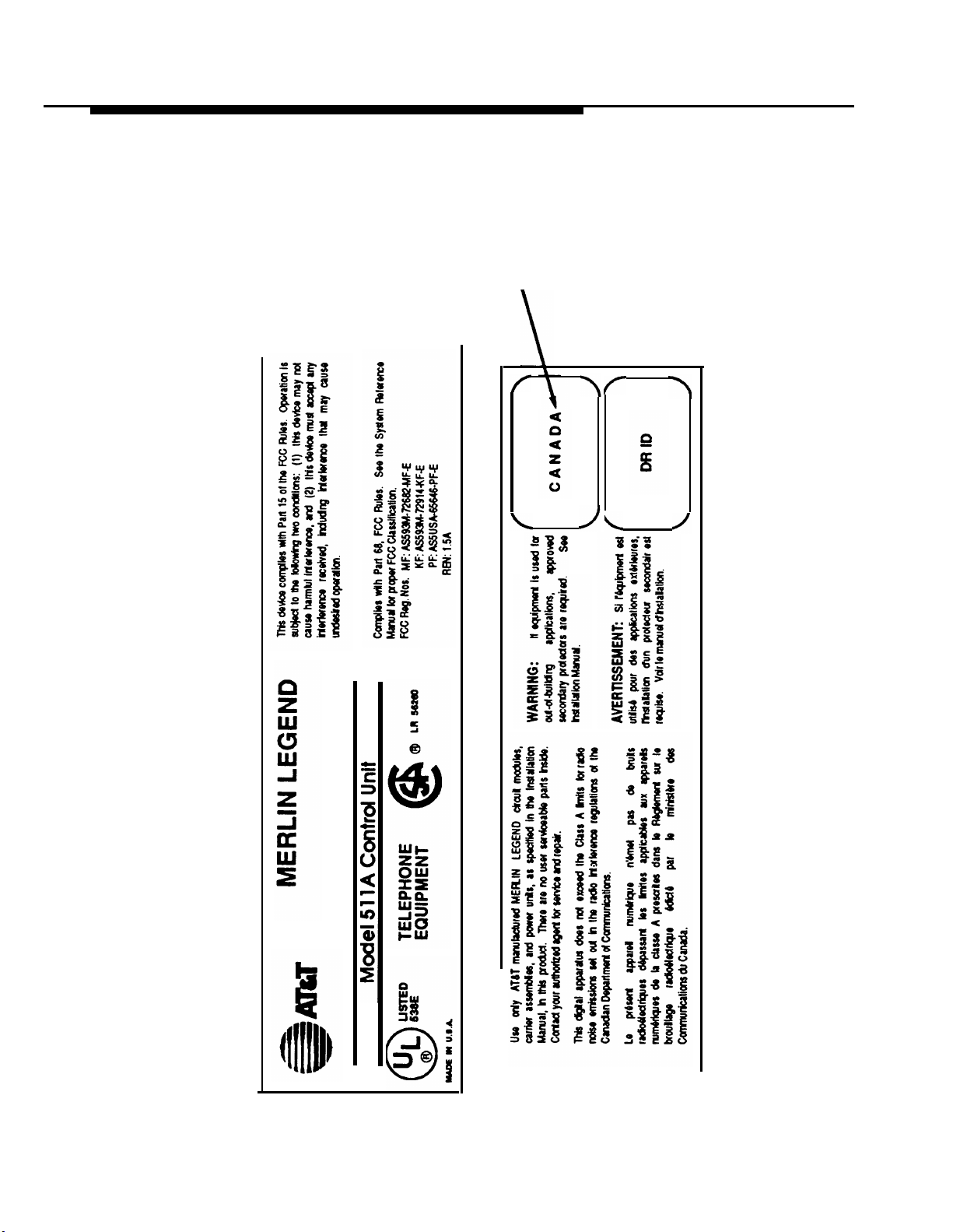
Customer Support Information
MERLIN LEGEND D.O.C.
Location Label Placement
Ministère des Communications
du Canada emplacement de
l'étiquette
xxii
Customer Support Information
Page 25

Customer Support Information
Security of Your System—Preventing Toll Fraud
As a customer of a new telephone system, you should be aware that there exists an
increasing problem of telephone toll fraud. Telephone toll fraud can occur in many
forms, despite the numerous efforts of telephone companies and telephone equipment
manufacturers to control it. Some individuals use electronic devices to prevent or
falsify records of these calls. Others charge calls to someone else’s number by
illegally using lost or stolen calling cards, billing innocent parties, clipping on to
someone else’s line, and breaking into someone else’s telephone equipment physically
or electronically. in certain instances, unauthorized individuals make connections to
the telephone network through the use of remote access features.
The Remote Access feature of your system, if you choose to use it, permits offpremises callers to access the system from a remote telephone by using an 800
number or a 7- or 10-digit telephone number. The system returns an
acknowledgement signaling the user to key in his or her authorization code, which is
selected and administered by the system manager. After the authorization code is
accepted, the system returns dial tone to the user. If you do not program specific
egress restrictions, the user will be able to place any call normally dialed from a
telephone associated with the system. Such an off-premises network call is originated
at, and will be billed from the system location.
The Remote Access feature, as designed, helps the customer, through proper
administration, to minimize the ability of unauthorized persons to gain access to the
network. Most commonly, phone numbers and codes are compromised when
overheard in a public location, through theft of a wallet or purse containing access
information, or through carelessness (writing codes on a piece of paper and improperly
discarding it). Additionally, hackers may use a computer to dial an access code and
then publish the information to other hackers. Enormous charges can be run up
quickly. It is the customer’s responsibility to take the appropriate steps to properly
implement the features, evaluate and administer the various restriction levels, protect
access codes, and distribute access codes only to individuals who have been fully
advised of the sensitive nature of the access information.
Common carriers are required by law to collect their tariffed charges. While these
charges are fraudulent charges made by persons with criminal intent, applicable tariffs
state that the customer of record is responsible for payment of all long-distance or
other network charges. AT&T cannot be responsible for such charges and will not
make any allowance or give any credit for charges that result from unauthorized
access.
Customer Support Information xxiii
Page 26

Customer Support Information
To minimize the risk of unauthorized access to your communications system:
■
Use a nonpublished Remote Access number.
Assign authorization codes randomly to users on a need-to-have basis,
■
keeping a log of ALL authorized users and assigning one code to one person.
Use random sequence authorization codes, which are less likely to be easily
■
broken.
■
Deactivate all unassigned codes promptly.
Ensure that Remote Access users are aware of their responsibility to keep the
■
telephone number and any authorization codes secure.
When possible, restrict the off-network capability of off-premises callers, via
■
use of Call Restrictions and Disallowed List capabilities.
When possible, block out-of-hours calling.
■
Frequently monitor system call detail reports for quicker detection of any
■
unauthorized or abnormal calling patterns.
■
Limit Remote Call Forward to persons on a need-to-have basis.
Limited Warranty and Limitation of Liability
AT&T warrants to you, the customer, that your MERLIN LEGEND Communications
System will be in good working order on the date AT&T or its authorized reseller
delivers or installs the system, whichever is later (“Warranty Date”). If you notify AT&T
or its authorized reseller within one year of the Warranty Date that your system is not in
good working order, AT&T will without charge to you repair or replace, at its option, the
system components that are not in good working order. Repair or replacement parts
may be new or refurbished and will be provided on an exchange basis. If AT&T
determines that your system cannot be repaired or replaced, AT&T will remove the
system and, at your option, refund the purchase price of your system, or apply the
purchase price towards the purchase of another AT&T system.
Voice Mail Systems
Your Voice Mail system permits callers to leave verbal messages for system users or
gain access to the back-up position in an emergency as well as create and distribute
voice messages among system users.
The Voice Mail system, through proper administration, can help you reduce the risk of
unauthorized persons gaining access to the network. However, phone numbers and
authorization codes can be compromised when overheard in a public location, are lost
through theft of a wallet or purse containing access information, or through
carelessness (writing codes on a piece of paper and improperly discarding them).
Additionally, hackers may use a computer to dial an access code and then publish the
information to other hackers. Substantial charges can accumulate quickly. It is your
xxiv
Customer Support Information
Page 27

Customer Support Information
responsibility to take appropriate steps to implement the features properly, evaluate
and administer the various restriction levels, protect and carefully distribute access
codes.
Under applicable tariffs, you will be responsible for payment of toll charges. AT&T
cannot be responsible for such charges and will not make any allowance or give any
credit resulting from unauthorized access.
To reduce the risk of unauthorized access through your Voice Mail system, please
observe the following procedures:
■
Employees who have voice mailboxes should be required to use the
passwords to protect their mailboxes.
— Have them use random sequence passwords.
— Impress upon them the importance of keeping their passwords a
secret.
— Encourage them to change their passwords regularly.
The administrator should remove any unneeded voice mailboxes from the
■
system immediately.
AUDIX Voice Power™ has the ability to limit transfers to subscribers only. You
■
are strongly urged to limit transfers in this manner.
Use the PBX or Key system administration capability to do the following:
■
— Block direct access to outgoing lines and force the use of account
codes/authorization codes.
— Disallow trunk-to-trunk transfer unless required.
— Assign toll restriction levels to all AUDIX Voice Power ports.
— If you do not need to use the Outcalling feature, completely restrict the
outward calling capability of the AUDIX Voice Power ports.
Monitor SMDR reports or Call Accounting System reports for outgoing calls that
■
might be originated by AUDIX Voice Power ports.
.
Remote Administration and Maintenance
The Remote Administration and Maintenance feature of your telecommunications
system, if you choose to use it, permits users to change the system features and
capabilities from a remote location.
The Remote Administration and Maintenance feature, through proper administration,
can help you reduce the risk of unauthorized persons gaining access to the network.
However, telephone numbers and authorization codes can be compromised when
overheard in a public location, are lost through theft of a wallet or purse containing
access information, or through carelessness (writing codes on a piece of paper and
improperly discarding them). Additionally, hackers may use a computer to dial an
access code and then publish the information to other hackers. Substantial charges
Customer Support Information xxv
Page 28

Customer Support Information
can accumulate quickly. It is your responsibility to take appropriate steps to implement
the features properly, evaluate and administer the various restriction levels, and protect
and carefully distribute access codes.
Under applicable tariffs, you will be responsible for payment of toll charges. AT&T
cannot be responsible for such charges and will not make any allowance or give any
credit resulting from unauthorized access.
To reduce the risk of unauthorized access through Remote Administration and
Maintenance, please observe the following procedures:
■
The System Administration and Maintenance capability of a PBX or Key system
is protected by a password.
— Change the default password immediately.
— Continue to change the password regularly.
— Only give the password to people who need it and impress upon them
the need to keep it secret.
— If anyone who knows the password leaves the company, change the
password immediately.
■
If you have a special telephone line connected to your PBX or Key system for
Remote Administration and Maintenance, you should do one of the following:
— Unplug the line when it is not being used.
— Install a switch in the line to turn it off when it is not being used.
— Keep the Remote Administration and Maintenance telephone number
secret. Only give it to people who need to know it, and impress upon
them the need to keep it a secret. Do not write the telephone number
on the PBX or Key system, the connecting equipment, or anywhere
else in the system room.
■
If your Remote Administration and Maintenance feature requires that someone
in your office transfer the caller to the Remote Administration and Maintenance
extension, you should impress upon your employees the importance of only
transferring authorized individuals to that extension.
xxvi
Customer Support Information
Page 29

About This Book
The Installation guide contains information on installing and upgrading the
MERLIN LEGEND
TM
Communications System.
Intended Audience
This book is intended for qualified technicians who install and upgrade the
system.
Conventions
The following typographical conventions are used in this book:
■ Bold type is used for telephone buttons.
Press
■ Italic type is used for emphasis and as a substitute for information for
which you must supply a specific value.
Drop
to delete the current entry.
Dial feature code; dial ✱ ext. no.
Conventions 1
Page 30

About This Book
■
Constant width type is used for information on telephone display
screens or on a PC screen.
Select
■ Bold constant width type indicates
Sys Program.
nformation that you enter
exactly as shown.
Type
install;
■ Keys on the PC are shown in boxes.
Press
■ When two keys are to be pressed at the same time, the keys are
[F7]
.
dial
#55.
connected by a hyphen.
Press
[Alt]
-
[P]
.
Product Safety Labels
Throughout these documents, hazardous situations are indicated by an
exclamation point inside a triangle and the-word “caution” or “warning.”
WARNING:
Warning indicates the presence of a hazard that could cause death
or severe personal injury if the hazard is not avoided.
CAUTION:
Caution indicates the presence of a hazard that could cause minor
personal injury or property damage if the hazard is not avoided.
2
Product Safety Labels
Page 31

About This Book
Related Documents
The books listed below comprise the entire MERLIN LEGEND
Communications System family of documentation. These documents are
listed by their abbreviated titles. For example, MERLIN LEGEND, Release 2.0
Communications System Installation is referred ‘to as installation.
To order these books, call the Customer Information Center (CIC). Check the
inside front cover for the telephone number.
NOTE:
For any application that runs on the system, you can also order
documentation from the CIC. If you do not know the exact title or number,
they can provide
you with a list of all documentation for each application.
Document No.
555-620-114
555-620-110
555-620-115
555-620-116
555-620-111
555-620-112
555-620-113
555-620-122
555-620-123
555-620-150
555-620-152
555-620-124
555-620-125
555-620-151
Title
System Documents
System Overview
Feature Reference
Equipment and Operations Reference
Pocket Reference
System Programming
System Planning
System Planning Forms
Telephone User Support
MLX-10D™, MLX-28D™, and MLX-20L™
Display Telephones User’s Guide
MLX-10D, MLX-28D, and MLX-20L
Display Telephones Quick Reference
MLX-10D Telephone Tray Cards (6 cards)
MLX-28D and MLX-20L Telephone Tray Cards (5 cards)
MLX-10™ Non-Display Telephone User’s Guide
MLX-10 Non-Display Telephone Quick Reference
MLX-10 (non-display) Telephone Tray Cards (6 cards)
Related Documents 3
Page 32

About This Book
Document No.
555-620-120
555-620-121
555-620-128
555-620-126
555-620-127
555-620-134
555-620-135
555-620-132
555-620-133
555-620-136
555-620-137
555-620-130
555-620-131
555-620-129
Title
Analog Multiline Telephones User’s Guide
Analog Multiline Telephones Quick Reference
MLC-5 Cordless Telephone Quick Reference
Single-Line Telephones User’s Guide
Single-Line Telephones Quick Reference
System Operator Support
MLX Direct-Line Consoles Operator’s Guide
MLX Direct-Line Consoles Quick Reference
Analog Direct-Line Consoles Operator’s Guide
Analog Direct-Line Consoles Quick Reference
MLX Queued Call Console Operator’s Guide
MLX Queued Call Console Quick Reference
Miscellaneous User Support
Calling Group Supervisor’s Guide
Calling Group Supervisor’s Quick Reference
Data User’s Guide
555-620-140
555-620-141
555-620-142
555-620-143
555-620-144
Documentation for Qualified Technicians
Installation, Programming, & Maintenance (lP&M) Binder
(consists of 555-620-141, 555-620-142, 555-620-143,
and 555-620-144)
Installation
System Programming & Maintenance (SPM)
Maintenance and Troubleshooting
Programming Summary
Related Documents
4
Page 33

About This Book
How to Comment on This Document
We welcome your comments, both good and bad. Please use the feedback
form on the next page to let us know how we can continue to serve you.
If the feedback form is not included in this section, write directly to the
following address:
A. Sherwood
AT&T
99 Jefferson Road
Room 2A25
Parsippany, NJ 07054
How to Comment on This Document 5
Page 34

Introduction to Installation
1
Installation of the MERLIN LEGEND Communications System, involves the
following:
■ installing the control unit
■ installing the telephones
■ connecting the system wiring
■ installing optional equipment
Optional equipment, such as a data module, printer, and various adjuncts
may be connected to the control unit. This chapter provides an overview of
the entire installation process, which varies from customer to customer.
Introduction to Installation 1-1
Page 35

Introduction to Installation
Overview of the Installation Process
The following is a comprehensive list of everything that the system could
include. When installing your customer’s system, try to adhere to this order as
much as possible.
1.
Install the control unit (required).
See Chapter 2.
2.
Connect power accessories to the control unit (optional).
See Chapter 2.
Install the telephones (required) and adjuncts (optional).
3.
See Chapter 3.
4.
Connect the telephones to the control unit (required).
See Chapter 3.
5.
Connect the control unit to the network interface (required).
See Chapter 4.
6.
Connect the channel service unit to the 100D module on the control
unit (required only with the 100D module).
See Chapter 4.
7.
Connect the printer and PC to the control unit (optional).
See Chapter 5.
Connect data equipment to the control unit (optional).
8.
See Chapter 6.
Initialize and test the system (required).
9.
See Chapter 7.
10. Install the control unit housing (required).
See Chapter 7.
11. Install applications (optional).
See Chapter 8.
.
1-2
Overview of the Installation Process
Page 36

Introduction to Installation
Tools and Equipment
A list of required tools and equipment is provided just before each procedure
throughout this guide.
System Forms
Throughout this guide, the installation procedures refer to system forms.
These forms indicate information that is specific to your customer’s system.
The forms that you need should be included with the system programming
diskette, which contains all of the programming specifically for your
customer’s system.
If you find that you do not have a fully completed set of planning forms for
your customer’s system, contact your technical support organization or the
Customer Service Center (CSC). See the inside of the front cover for
telephone numbers.
Using the System Forms
Not all of the system forms are necessary for each system.
The following sections list the forms according to the following categories:
■ Installing the control unit
■ Installing telephones and adjuncts
■ Connecting the network interface
■ Connecting data equipment
■ Programming the system
System Forms
1-3
Page 37

Introduction to Installation
Installing the Control Unit
■ Form 1, System Planning (the Control Unit Diagram on the back)
■ Form 3c, Incoming Trunks—Tie
Some of the procedures in Chapter 2 refer to the Control Unit Diagram, which
is the second side of Form 1, System Planning.
If you are installing a 400EM module in the control unit, you need Form 3c,
Incoming Trunks—Tie to determine the switch settings prior to installing the
module in the control unit.
Installing Telephones and Adjuncts
The following forms indicate the telephones and adjuncts that are to be
installed, as described in Chapter 3.
■ Form 2a, System Numbering—Station Jacks
■ Form 2b,
■ Form 4b,
■ Form 4d,
■ Form 4e,
■ Form 4f, Tip/Ring Equipment
■ Form 5a, Direct-Line Console (DLC)—Analog
■ Form 5b, Direct-Line Console (DLC)—Digital
■ Form 5c, MFM Adjunct—DLC
■ Form 5d, Queued Call Console (QCC)
System Numbering—Digital Adjuncts
Analog Multiline Telephone
MLX Telephone
MFM Adjunct—MLX Telephone
Connecting the Network Interface
The following forms indicate the trunks that are to be connected to the control
unit. Information regarding the channel service unit is indicated as well. This
information is needed to perform the procedures in Chapter 4.
-
1-4 System Forms
Page 38

Introduction to Installation
■ Form 2c, System Numbering—Trunk Jacks
■ Form 3a, Incoming Trunks—Remote Access
■ Form 3b, Incoming Trunks—DS1 Connectivity
■ Form 3d, Incoming Trunks—DID
(100D Module)
Connecting Data Equipment
The following forms indicate the data equipment needed to setup data
stations and modem pools, as described in Chapter 6:
■ Data Form 1a,
■ Data Form 1b,
■ Data Form 2a,
■ Data Form 2b,
■ Data Form 3, Data Hunt Groups
Modem Pool—Analog to Digital
Modem Pool—Digital to Analog
Analog Data Station
Digital Data Station
Programming the System
If you have a system programming diskette that was created using SPM, you
do not need to program the system. Use that diskette to restore the system
as described in Chapter 7. If you did not receive this diskette and it is your
responsibility to program the system, see the System Programming guide for
instructions. Each programming procedure indicates the appropriate form.
System Forms
1-5
Page 39

Introduction to Installation
Upgrading the Communications System
If you are upgrading to Release 2.0 from Release 1.0, 1.1, or from the
MERLIN® II Communications System, see Chapter 7 for the upgrade
procedure.
NOTE:
You cannot upgrade the system software from the MERLIN II
Communications System. You can upgrade only the hardware.
1-6
Upgrading the Communications System
Page 40

Installing the Control Unit
2
If you have not read Chapter 1, do so before continuing with any instructions
in this chapter.
Overview
Installing the control unit involves the following, which this chapter describes
in detail:
1. Installing the backboard
2. Meeting the power and grounding requirements
3. Checking the total unit load
4. Installing the basic carrier
5. Installing any expansion carriers specified for the system
6. Installing the power supply
7. Installing the processor
8. Installing the trunk/station modules
These are referred to as modules throughout this guide.
Overview 2-1
Page 41

Installing the Control Unit
9. Connecting the control unit to AC power
10. Powering up the system
11. Powering down the system
Be sure to follow these procedures in the order specified.
Preparation
The control unit must be installed on a backboard, which may already be
installed. If so, skip to the section, “Power and Grounding.”
If backboard installation is your responsibility, follow the procedures in this
section.
Environment
The placement of the control unit requires careful consideration. Make sure
you install the backboard in an area that meets all of the environmental
requirements listed in Table 2-1.
2-2
Preparation
Page 42

Installing the Control Unit
Table 2-1. Environmental Requirements
Operating
Temperatures
Humidity
Airborne
Contamination
40° - 104°F (4° - 40°C)
Optimum temperature: 60°F (15.6°C)
20%-80%
Do not expose the control unit to moisture, corrosive gases,
dust, chemicals, spray paint, or similar material.
Ventilation Allow at least 1 inch (2.54 cm) on the right and left sides of
the control unit and 12 inches (31 cm) above and below to
prevent overheating.
Do not place the control unit near extreme heat (for
example: furnaces, heaters, attics, or direct sunlight).
Electrical
Fields
Heat
Dissipation
Do not expose the control unit to devices that generate
electrical currents causing interference (such as arc
welders or motors).
Basic carrier: 500 BTU/hr
Basic carrier with one expansion carrier: 1000 BTU/hr
Basic carrier with two expansion carriers: 1500 BTU/hr
WARNING:
Do not install the control unit outdoors.
Electrical Noise/Radio-Frequency Interference (RFI)
In most cases, electrical noise is introduced to the system through trunk or
telephone cables. However, electromagnetic fields near the control unit may
also induce noise in the system. Therefore, the control unit and cable runs
should not be placed in areas where a high electromagnetic field strength
exists.
Preparation 2-3
Page 43

Installing the Control Unit
Radio transmitters (AM or FM), television stations, induction heaters, motors
(with commutators) of 0.25 horsepower (200 watts) or greater, and similar
equipment are leading causes of interference. Small tools with universal
motors are generally not a problem when they operate on separate power
lines. Motors without commutators generally do not cause interference.
Field strengths below 1.0 volt per meter are unlikely to cause interference.
The field strength produced by radio transmitters can be estimated by
dividing the square root of the emitted power in kilowatts by the distance from
the antenna in kilometers. This yields the approximate field strength in volts
per meter and is relatively accurate for distances greater than about half a
wavelength (492 ft, or 150 m, for a frequency of 1000 Hz). See the Customer
Support Information in the beginning of this guide for FCC Part 15 radio
frequency regulations.
Control Unit Requirements
■ Dimensions
— Basic carrier: 14” W x 23” H x 12” D
— Basic carrier and one expansion carrier:
25” W x 23” H x 12” D
— Basic carrier and two expansion carriers:
37” W x 23” H x 12” D
■ Location
— Within 5 ft
controlled
— Within 25 ft (762 cm) of the network interface—or use an off-
premises range extender (OPRE)
— Within 1000 cable feet (305 m) of telephones— or use an OPRE
(for basic telephones)
(152 cm) of AC power outlet that is not switch-
2-4
Preparation
Page 44

Installing the Control Unit
Backboard Requirements
The backboard should be wide enough to accommodate additional carriers if
system growth is anticipated. In addition to the basic carrier, two expansion
carriers can be added.
To accommodate the maximum control unit size, make sure the backboard
meets the following requirements:
■ Dimensions
— with SYSTIMAX wiring: 7’ W x 4’ H x 3/4” D
— without SYSTIMAX wiring: 6’ W x 3’ H x 3/4” D
■ Material
— 3/4” plywood
— Check with local building code enforcement agency to see if
fire-retardant material is required.
— Make sure that the material meets local building code
requirements.
Installing the Backboard
When you are certain that the backboard and its location meet the
requirements indicated in this section, attach the backboard to the wall,
allowing enough room on either side of the control unit for necessary wiring
fields and future addition of expansion carriers.
Use the following mounting hardware:
■ For a wood mounting surface, use woodscrews.
■ For brick, cinder block, or concrete, use masonry anchors.
■ For plaster or plasterboard, use toggle bolts.
■ For sheet-metal, use sheet-metal screws and attach them to the
structural members.
Preparation
2-5
Page 45

Installing the Control Unit
NOTE:
The combined pullout force of the backboard should be at least 650
pounds (295 kilograms).
Power and Grounding
Proper power and grounding are essential for correct and safe functioning of
the system.
Use
this section to verify that all power and grounding requirements are met.
CAUTION:
If any of these requirements are not met, have the customer contact
a licensed electrician. Do not install the system until all requirements
are met.
The load center of appropriate current rating must be equipped with
■
circuit breaker(s) labeled
■
Each breaker must protect one dedicated quad AC outlet or two
120 VAC, 15 amps.
dedicated duplex AC outlets.
All AC outlets must be connected to the same load center and must
■
have the ground wire connected to the single-point ground bar on the
first AC outlet (see Figure 2-1).
■
One outlet must have an attached ground bar connected by a #6 AWG
copper wire to an approved ground. This ground bar is the system’s
single-point ground (see Figure 2-1).
2-6
Power and Grounding
Page 46

Installing the Control Unit
From AC
Load Center
(2 separately
fused 15 A
circuits)
HUBBELL Receptacles
(5262 15 A
or equivalent)
TYPICL AC GROUNDING
Ground
(#14 AWG)
4" Box (RACO 230
or equivalent)
Single-Point
Ground
Ground Bar
Mounted on a 4" Box
(Square "D" PK9GTA or
approved equivalent)
Building Ground
(#6 AWG Copper)
#12 or #14 AWG Copper
Wire to EAch Power Supply
Grounding Screw
(RACO 807
or equivalent)
Approved
Figure 2-1. AC Grounding Requirements
■ Each carrier requires one outlet receptacle.
■ Additional AC outlets may be required for auxiliary equipment.
■ If a printer or a PC is to be installed with the system, it must be
plugged into the same AC branch as the power supply of the basic
carrier.
If the printer or PC is 50 ft (15 m) or more from the control unit or is
plugged into a different AC circuit, asynchronous data units (ADUs)
must be installed as well. Complete installation instructions are
provided in Chapter 5.
4" Cover
Power and Grounding
2-7
Page 47

Installing the Control Unit
■ The AC power requirements indicated in the next section, “AC Outlet
Tests” must be met.
CAUTION:
The AC outlet for the control unit cannot be switch-controlled.
Plugging the control unit into such an outiet invites accidental
disconnection of the system. The AC outlet must be properly wired
as described in the next section, “AC Outlet Tests.”
AC Outlet Tests
If the AC outlet tests indicate that any of the power requirements in Table 2-2
are not met, your customer must contact a licensed electrician. Do not install
the system until all requirements are met.
Table 2-2. AC Power Requirements
Parameter
Nominal voltage
Voltage range
Frequency
Maximum current
Power consumption
117
110-125
60±5%
3 per power supply
225 per power supply
Value
Unit
VAC
VAC
Hz
amps
watts
2-8
Power and Grounding
Page 48

Installing the Control Unit
If the AC outlet tests reveal any of the following conditions, they must be
corrected before you install the system:
■ open ground
■ hot and neutral
■ open hot
■ open neutral
■ hot and ground
reversed
reversed
WARNING:
Hazardous voltages are present during the following tests. Follow all
instructions carefully when working with AC power line voltages.
Using an Ideal 61-035 Circuit Tester (or Equivalent)
1.
Plug the circuit tester -into the outlet to be tested.
If the circuit is properly grounded, the yellow and white lights on the
tester turn on.
A
2.
Using a
1.
2.
Unplug the circuit tester.
Volt-Ohm Milliammeter (VOM)
Set the VOM to the scale on which you can read 130 VAC.
Measure the AC outlet voltages (see Figure 2-2).
Power and Grounding 2-9
Page 49

Installing the Control Unit
110 - 125
Volts
Figure 2-2.
Neutral
Less than
2.5 Volts
Phase
(HOT)
Ground
110 - 125
Volts
Measuring the AC Outlet Voltages
■
Phase to ground should be 110 to 125 VAC.
■
Neutral to ground should be less than 1 VAC.
■
Phase to neutral should be 110 to 125 VAC.
WARNING:
If the voltage readings do not measure the values required,
the AC outlet is improperly wired: do not install the system.
Advise the customer to have a licensed electrician correct the
problem.
2-10
Power and Grounding
Page 50

Installing the Control Unit
Grounding Requirements
Proper grounding of the installation site safeguards system functioning by
protecting the system from the following:
■ lightning
■ power surges
■ power crosses on central office trunks
■ electrostatic discharge (ESD)
When installing the control unit, make sure that you meet the following
grounding requirements:
The control unit, the central office trunk protector, and the AC power
■
service panel should be as close to each other as possible.
Because equipment can be located throughout a building, the National
■
Electrical Code requires that the ground point for the central office
trunk protector be bonded to the AC power ground as shown in
Figure 2-3.
The AC outlet and the single-point ground bar must be properly
■
grounded as shown earlier in Figure 2-1.
■
Each power supply in the control unit must be connected to the
single-point ground bar by a #12 AWG or a #14 AWG solid copper
wire. Figures 2-1 and 2-3 show this connection.
This wire run should be as short as possible, preferably within 5 ft
(152 cm), not to exceed 10 ft (305 cm). This procedure is described
later in this chapter under “Providing the Proper Grounding.”
The AC outlet must be connected to the 147A protector with #12 AWG
■
or a #14 AWG solid copper wire.
Power and Grounding
2-11
Page 51

Installing the Control Unit
To
Central
Office
or
Serving
Facility
CO
Lines
CO
Line
Protector
Network
Interface
Power
Supply
DIW or 25-Pair Cable
Coupled Bonding
Conductor (optional)
CO
Wiring
Field
D2R Cords
Commercial
Power
Ground
Wire
Earth
Ground
#6 AWG
Bond
Wire
Plug
Power
Ground
Rod
Outlet
Figure 2-3. Central Office and AC Grounds
2-12
Power and Grounding
AC
Single Point
Ground
Bar
Shield
Ground
B
W
GND (Green)
Power
Service
Page 52

Installing the Control Unit
WARNING:
Improper ground can cause equipment failures, service outages,
and electrical shock. Verify that the AC power uses an approved
ground for its primary ground, that all voltage-limiting devices are
grounded to an approved ground, and that the ground is one of the
approved grounds listed below.
Approved Grounds
The following is a list of approved grounds, starting with the most preferred:
■ building steel
■ acceptable water pipe—must be a metal, underground water pipe at
least ½-inch (30.4 cm) in diameter, and in direct contact with the earth
for at least 10 ft (3 m).
It must be electrically continuous so that the protector ground is
connected. (Check for insulated joints, plastic pipe, and plastic water
meters that might interrupt electrical continuity.)
A metallic underground water pipe must be supplemented by the
metal frame of the building, a concrete-encased ground, or a ground
ring. If these grounds are not available, the water pipe ground can be
supplemented by one of the following types of grounds:
—
other local metal underground systems or structures—local
underground structures such as tanks and piping systems
— rod and pipe electrodes—a 5/8 -inch (1.6-cm) solid rod or
¾-inch (1.9-cm) conduit or pipe electrode driven to a minimum
depth of 8 ft (244 cm)
— plate electrode—a minimum of 2 square ft (61 square cm) of
metallic surface exposed to the exterior soil
Power and Grounding
2-13
Page 53

Installing the Control Unit
■ concrete-encased ground—must be an electrode, consisting of one of
the following:
—
at least 20 ft (6.1 m) of one or more steel reinforcing rods, each
being at least ½-inch (1.27 cm) in diameter
— 20 ft (6.1 m) of bare copper conductor not smaller than
#4 AWG, encased in 2 inches (5 cm) of concrete.
— This electrode must be located within and near the bottom of a
concrete foundation or footing that is in direct contact with the
earth.
— ground ring-consists of at least 20 ft (6.1 m) of bare copper
conductor not smaller than #2 AWG encircling the building.
The ground ring must be in direct contact with the earth and
buried at least 2.5 ft (77 cm) below the earth’s surface.
WARNING:
Do not use metal underground gas piping system—this is a
safety risk.
Central Office Trunk Protection
The telephone company is responsible for providing the following protection
of central office trunks at the entrance to the site:
■ carbon blocks or gas discharge tubes connected to an approved
ground
■ adequate bonding of the central office trunk protector ground and the
power company ground
2-14
Power and Grounding
Page 54

Installing the Control Unit
CAUTION:
Check these requirements with a simple, visual inspection; if you
cannot verify that the central office grounding requirements are met,
contact the central office. Do not connect the centrai office trunks
until you are ceflain that these requirements are met.
Heavy Lightning Protection
For most surges, adequate protection is provided by meeting the
requirements listed in the previous section, “Grounding Requirements.”
Additional protection is required when the customer is located in a heavy
lightning area:
Connect a 147A protector to the system to limit surges from the AC lines and
central office trunks.
One 147A protector provides protection for four central office trunks.
■ Connect a 146A protector to the 147A to provide protection for another
four trunks.
You can connect as many as three 146A protectors to a 147A, which
allows a maximum of 16 central office trunks on one 147A protector.
■ For more than 16 trunks, add another 147A protector and continue
adding 146As as needed.
See Table 2-3 for various configurations.
See Figure 2-4 for a typical 147A protector installation.
Power and Grounding
2-15
Page 55

Installing the Control Unit
Table 2-3. Heavy Lightning Protection
If you have
this number of
central office trunks . .
1-4
5-8
9-12
13-16
17-20
21-24
Connect these protectors
.
147A
147A and a 146A
147A and two 146As
147A and three 146As
Two 147As and three 146As
See the note below.
Two 147As and four 146As
See the note below.
NOTE:
When you use the additional 147A, you can connect the 146As in any
combination, up to a maximum of three 146As per 147A. For example, if
you have only enough wall space for two 146As and a 147A, put two
146As with the first 147A, and then put the third 146A with the additional
147A.
2-16
Power and Grounding
Page 56

Installing the Control Unit
Connect telecommunications
equipment only to these outlets.
CONTROL UNIT
TEL CO LINE
CONTROL UNIT
TEL CO LINE
Status
Indicator
Light
Ground
Strap
Maximum load 12.5A
AC Surge
Protector
147A Protector
146A Protector
Ground
Strap
CONTROL UNIT
TEL CO LINE
CONTROL UNIT
TEL CO LINE
Central Office
Cross-Connect
Field
To
To
Control Unit
AC
Outlet
Power Strip
Ground
Wires
12 or 14
AWG
Figure 2-4. Installing 146A and 147A Protectors
For more detailed installation instructions, see the documentation packaged
with the protectors.
Power and Grounding
2-17
Page 57

Installing the Control Unit
Unit Loads
A unit load is a measure of power (1.9 watts) used to determine the electrical
load that the following components have on each carrier’s power supply:
■ telephones and adjuncts
Only the telephones and adjuncts that connect to the analog and
digital ports on the control unit require unit load calculation. Do not
include any equipment with its own power supply in the unit load
calculation.
■ 800 DID modules
Checking Unit Loads
In the event of maintenance or equipment changes, recalculate the unit loads
for each carrier resulting in a different configuration.
Use the worksheet in Appendix B.
General Rule: If you can distribute the 800 DID modules and telephone
modules equally
across the carriers, you will prevent unnecessary drain on
any one carrier.
Also, depending
provide the rules
Unit Loads for
on the system’s mode, the rules vary. The next two sections
for calculating unit loads in various modes.
the Hvbrid/PBX Mode
The power supply (model 391A1) generally supports six modules of any type
in a Hybrid/PBX system—
without requiring an auxiliary power unit.
If, however, both of the following conditions are true, the unit loads on a
carrier can exceed the 54-unit maximum, and therefore require auxiliary
power:
■
all six carrier slots are occupied by MLX telephone or analog multiline
telephone modules
2-18 Unit Loads
Page 58

Installing the Control Unit
■ the carrier has a total of more than 45 MLX-20L telephones or 34-
button analog multiline telephones installed
Unit Loads for Key or Behind Switch Mode
In a Key or Behind Switch system with four or fewer modules, no calculation is
needed. The power supply (model 391A1) generally supports four modules
of any type in Key or Behind Switch mode.
Auxiliary Power Units
The power supply provides 54 unit loads to each carrier. If the unit load
requirement for a carrier exceeds 54, an auxiliary power unit is needed to
allow that carrier to support an additional 27 unit loads.
CAUTION:
Running the system with more than 54 unit loads per carrier may not
appear to do harm. However, this can cause the system to
malfunction, thereby creating “no trouble found” situations, such as
malfunctioning LEDs on multiline telephones, or power unit failure.
Any station connected to the modules in the last two slots receives power
from the auxiliary power unit instead of from the power supply.
If an auxiliary power unit is required, complete instructions are provided later
in this chapter, as the fourth step under “Installing the Processor.”
Unit Loads
2-19
Page 59

Installing the Control Unit
Installing the Basic Carrier
Begin this procedure only if you have met all of the requirements discussed
earlier in this chapter.
NOTE:
If you are upgrading a system, the basic carrier (and possibly one or two
expansion carriers) is already installed. Do not remove any of these
carriers; skip to the next section, “Upgrading the Control Unit.”
Following the instructions given below, mount the basic carrier onto the
plywood, leaving 5 inches (12.7 cm) of plywood to the left. This allows easy
access to the installation and removal of the system cover, while allowing
enough room for system expansion (up to a total of three carriers and
5 inches (12.7 cm) of plywood to the right of the third carrier).
1. Mark the screw hole locations on the backboard using the basic carrier
as a guide. See Figure 2-5.
Make sure the carrier is level before marking the holes.
Mounting Surface
Mounting
Screw
Background
Basic
Carrier
Figure 2-5. Marking the Basic Carrier Screw Holes
2-20
Installing the Basic Carrier
Page 60

Installing the Control Unit
2. Remove the carrier from the backboard and drill a pilot hole in the
center of each of the four screw-hole marks.
3. Anchor the screws approximately halfway into the backboard.
4. Place the housing clips around the molding for the screws on the back
of the carrier. See Figure 2-6.
NOTE:
Install all four housing clips if the system has only one carrier.
If an expansion carrier is to be added, install the housing clips only
on the left side of the basic carrier.
Figure 2-6. Installing the Housing Clips on the Carrier
5. Position the carrier on the screws and slide the carrier to the left.
6. Check to see that the carrier is level and that the housing clips extend
as far as possible from the sides of the carrier.
7. Tighten the screws.
Installing the Basic Carrier
2-21
Page 61

Installing the Control Unit
Upgrading the Control Unit
When upgrading, do the following:
1. Remove the control unit housing:
a. Disconnect AC power from each auxiliary power unit at the wall
outlet.
b. Disconnect AC power from each carrier by disconnecting the
power cord at the wall outlet.
c. If the existing control unit is a MERLIN II Communications
System, remove the housing as follows. See Figure 2-7.
i.
Remove the front housing from each carrier by pulling the
bottom-front towards you. When it releases, remove it by
lifting up as shown in Figure 2-7.
ii.
Remove the top from each carrier. in the system by
pushing it straight up from the front.
iii. Discard the MERLIN II Communications System housing.
d. If the existing control unit is a MERLIN LEGEND Communications
System, remove the housing as follows. See Figure 2-7.
i.
From both sides of the control unit, pry the clips from the
housing, using a screwdriver if difficult to reach.
ii. When the clips are freed from the housing, carefully pull
the housing towards you.
NOTE:
If the system has more than one carrier, make sure
you hold the housing only from the basic carrier side.
Otherwise, the housing may disassemble.
iii. Do not discard the housing, unless new housing is
provided. You will reassemble the housing when
installation of the entire system is complete, as described
in Chapter 7.
2-22
Upgrading the Control Unit
Page 62

Installing the Control Unit
MERLIN II
Communications System
MERLIN LEGEND
Communications System
Figure 2-7. Removing the Control Unit Housing
2. Do not remove any of the existing carriers.
3. Power down the system as described later in this chapter, under
“Powering Down the System.”
Upgrading the Control Unit
2-23
Page 63

lnstalling the Control Unit
.
4. See the Control Unit Diagram on Form 1, System Planning.
If you will be adding an expansion carrier, remove the rightmost
module from the control unit and put it aside.
CAUTION:
If you remove the cords from the module, make sure they are
labeled first.
5. If housing clips are already installed on the existing control unit,
remove them:
Remove the rightmost module from the control unit. See
a.
“Removing a Module” later in this chapter for instructions.
Using a flat-blade screwdriver, unscrew the upper-right corner of
b.
the carrier only far enough to free the clip.
Pull the top-right corner of the carrier toward you while grasping
c.
the housing clip and pushing it away from you (to free it from the
carrier).
When the clip is free enough to clear the screw molding on the
back of the carrier, slide the clip out and discard it.
d.
Compare the Control Unit Diagram with the existing control unit.
If you will be installing an additional expansion carrier in this
upgrade, do not replace the clip on the right side until the last
expansion carrier is installed. If no more carriers are to be
installed, replace the clip now, making sure the clip is as far to
the right as possible.
e.
Secure the screw, and then repeat Steps b, c, and d for the
lower-right corner of the carrier.
2-24
Upgrading the Control Unit
Page 64

lnstalling the Control Unit
6. Remove the power supply as follows:
a. Press upon the tab at the bottom rear of the power supply.
b. While the tab is unlocked, pull the power supply towards you,
and
then lift it straight up.
WARNING:
Beware of hazardous voltages; whenever the carrier
connections are exposed, use extreme caution; do not
touch them directly or with any type of tool. Follow all
procedures carefully.
7. Remove the clips from the left side of the control unit in the same way;
however, make sure you replace the clips before securing the screws
again.
8. If not already installed, install the new clips on the left side of the
control unit:
a. Using a flat-blade screwdriver, unscrew the upper-left corner of
the carrier only enough to slide a new clip behind the screw
molding on the back of the carrier.
b. With the clip in place, secure the screw, making sure the clip is
as far to the left as possible.
c. Repeat Steps a and b for the lower-left corner.
9. Reinstall the power supply by hooking it onto the rod at the top of the
carrier, and then swinging it down into place.
10. Push the power supply firmly until you hear it lock.
11. To install any expansion carriers, see the next section, “Installing
Expansion Carriers.”
12. To install or replace any modules, see “Installing the Modules,” later in
this chapter.
Upgrading the Control Unit 2-25
Page 65

Installing the Control Unit
Installing Expansion Carriers
If one or more expansion carriers is indicated for the system, follow this
procedure to mount each one (see Figure 2-8).
1. If you are adding an expansion carrier to an existing system, see the
previous section before continuing.
2. Locate the breakaway plastic tab on the right side of the previously
mounted carrier. Using a flat-blade screwdriver, gently pry the tab
open to expose the card extenders and connectors on the carriers.
BASIC CARRIER
CONNECTOR
CARD
EXTENDER
(under the
breakaway tab)
BACKBOARD
EXPANSION CARRIER
Figure 2-8. Connecting the Carriers
3. Align the connector of the expansion carrier with the card extender on
the previously mounted carrier and slide the connector onto the
extender.
2-26
4. Mark the screw hole locations on the backboard using the expansion
carrier as a guide. Make sure the carrier is level before marking the
holes.
Installing Expansion Carriers
Page 66

Installing the Control Unit
5.
Disconnect the expansion carrier connector from the previously
mounted carrier and put the expansion carrier aside.
6.
Drill a pilot hole in the center of each of the four screw-hole marks.
Anchor the screws approximately halfway into the backboard.
7.
If this is the last carrier in the system, place the control unit housing
8.
clips around the right-hand molding for the screws on the back of the
carrier.
If not, skip this step.
Position the expansion carrier on the screws and slide it to the left,
9.
thereby reconnecting the expansion carrier card extender to the
previous carrier’s connector.
10.
Make sure the connection is secure.
11.
Check to see that the carrier is level and that the housing clips extend
as far as possible from the right side of the carrier.
Tighten the screws.
12.
Installing Expansion Carriers
2-27
Page 67

Installing the Control Unit
Installing the Power Supply
WARNING:
■
Do not attach any cables or power cords to the power supply
until it is installed in the carrier.
■
Do not power up the control unit until all of the modules and
power equipment are installed.
Once they are installed, follow the procedures under
“Powering Up the System” later in this chapter. Failure to
comply with these procedures can result in shock hazard or
damage to the equipment.
If a ring generator is specified in the system forms (Control
■
Unit Diagram), install it in the power supply before putting the
power supply in the carrier. The detailed procedure is
provided in the section “Step 2a: Installing a Ring Generator,”
later in this chapter.
■
For expansion carriers only, a copper shield must be installed
on the power supply before installing it in the carrier. The
detailed procedure is provided in the section, see
“Step 3: Installing a Copper Shield.”
To prevent damage from electrostatic discharge (ESD), avoid
■
touching leads, connectors, pins, and other components.
Use a properly grounded wrist strap.
Remove the protective cover from the gold-finger connector
■
(on the back of the power supply) before inserting it into the
carrier.
2-28
Installing the Power Supply
Page 68

Installing the Control Unit
Installing the power supply can involve as many as four steps, depending on
the system configuration. The following procedure includes steps that require
detailed explanation. The detailed procedures for those steps immediately
follow this high-level procedure.
1. Make sure all power to the control unit is turned off.
See “Step 1: Turn Off the Power.”
2. Install a ring generator in the power supply if an 012 basic telephone or
008 OPT module is connected to the same carrier. See “Step 2a:
Installing a Ring Generator.”
NOTE:
Place all 012 modules and 008 OPT modules in one carrier
whenever possible.
3. Add a copper-foil shield to any power supply that is to be installed in
an expansion carrier. See “Step 3: Installing a Copper Shield.”
4. Install the power supply in the leftmost slot of each carrier. See
“Step 4: Installing the Power Supply into the Carrier.
Step 1: Turn off the Power
a. Make sure that each power supply is turned off.
b. Make sure all power cords and auxiliary units are disconnected.
Installing the Power Supply
2-29
Page 69

Installing the Control Unit
Step 2a: Installing a Ring Generator
If a ring generator (the 129B frequency generator) is indicated on the Control
Unit Diagram it must be installed in the power supply before installing the
power supply into the carrier.
NOTE:
■
This procedure is part of a larger procedure for installing the power
supply. If you have not already read the beginning of this section,
“Installing the Power Supply,” do so before continuing.
■
If you are replacing a ring generator, skip to the next section, “Step
2b: Replacing a Ring Generator.”
WARNING:
Hazardous electrical voltages may be present if the following steps
are not performed correctly.
Follow these steps to install a ring generator (see Figure 2-9 throughout this
procedure):
a. Make sure each power supply is turned off, including the module in the
control unit and any auxiliary power units.
b. Unplug the power supply cord from the AC outlet (or from the auxiliary
power unit) and then from the power supply.
NOTE:
At this point, all cords should be removed from the power supply.
c. Remove the power supply from the carrier.
d. Place the power supply on its left side and remove the five screws.
2-30
Installing the Power Supply
Page 70

Installing the Control Unit
WIRE
CLIP
P2
P1
RING GENERATOR
P202
P101
WIRE MANAGER:
MAKE SURE THE
MODIFICATION LABEL
IS ATTACHED WHEN
FINISHED: "EQUIPPED WITH
129B FREQ GEN"
Figure 2-9. Installing a Ring Generator in the Power Supply
e. Carefully turn the module over on its right side and then remove the top
of the power supply housing.
f.
Position the ring generator as shown in Figure 2-9 and align the screw
holes.
Installing the Power Supply
2-31
Page 71

Installing the Control Unit
.
NOTE:
Make sure the
of the power supply housing as the
board.
Secure the ring generator using the four screws, one in each corner.
g.
h.
Connect one end of the ring generator’s cable with the 3-pin
connectors to the header labeled
board.
NOTE:
This cable connector, as with all four cable connectors, is “keyed”
so that you cannot attach it to the header if it is turned the wrong
way.
P1
header on the ring generator is on the same side
P101
P101
header on the circuit
on the power supply circuit
i.
Connect the other end of the cable to the header labeled
ring generator.
NOTE:
The cable headers,
the housing, so that the cables do not cross each other.
Connect one end of the 4-pin cable to the header labeled
j.
power supply circuit board.
k.
Connect the other end of the cable to the header labeled
ring generator.
l.
Use the clips provided with the ring generator to attach the cables to
the inside edge of the plastic housing.
m.
Replace the top of the module housing.
P1
and
P101,
should be on the same side of
P1
P202
P2
on the
on the
on the
2-32
Installing the Power Supply
Page 72

Installing the Control Unit
NOTE:
Take time to ensure that the on/off faceplate on the front of the
power supply housing is aligned and inside the top cover.
n.
Carefully, taking time to make sure the on/off faceplate stays aligned,
turn the module over and replace the five screws on the housing.
Fasten the modification label
o.
the wire manager (on the front of the power supply as shown in
Figure 2-9).
Equipped with 129B Freq Gen
Step 2b: Replacing a Ring Generator
WARNING:
Hazardous electrical voltages may be present if the following steps
are not performed correctiy.
Follow these steps to replace a ring generator (see Figure 2-10 throughout
this procedure):
a. Make sure each power supply is turned off, including the module in the
control unit and any auxiliary power units.
b. Unplug the power supply cord from the AC outlet (or from the auxiliary
power unit) and then from the power supply,
to
NOTE:
At this point, all cords should be removed from the power supply.
c. Remove the power supply from the carrier.
d. Place the power supply on its left side and remove the five screws.
e. Carefully turn the module over on its right side and then remove the top
of the power supply housing.
Installing the Power Supply
2-33
Page 73

Installing the Control Unit
Steps a through e:
Open the power supply
Step f:
Detach cable
from wire clip
Step g:
Disconnect the P202 header
(pry the clip away from the header
and pull the header straight up)
P202
WIRE
CLIP
P2
RING GENERATOR
Step i:
Remove the four screws
(one in each corner of
the ring generator)
P1
Step f:
Detach cable
from wire clip
Grip here
P101
Step h:
Disconnect the
P101 header
(grip the sides and
pull forcefully)
Grip here
Step t:
Wire manager:
make sure the
modification label is
attached when finished;
"Equipped with 129B
Freq Gen"
Figure 2-10. Replacing a Ring Generator
f. Detach the cables from the inside edge of the plastic housing by
removing them from the clips.
2-34
Installing the Power Supply
Page 74

Installing the Control Unit
Disconnect the 4-pin cable from the header labeled P202 on the left
g.
side of the power supply circuit board.
As shown in Figure 2-10, you may need to pry back the clip to free the
cable.
h.
Disconnect the other cable from the header labeled P101 on the right
side of the power supply circuit board.
As shown in Figure 2-10, you need to grip this cable firmly and pull
forcefully.
i.
Remove the four screws from the ring generator as shown in
Figure 2-10.
Remove the ring generator.
j.
k.
Position the replacement ring generator as shown in Figure 2-10 and
align the screw holes.
P1
Make sure the
the power supply housing as the
l.
Replace the four screws and fasten them to secure the ring generator.
m.
Connect one end of the new ring generator’s cable with the 3-pin
connectors to the header labeled P101 on the power supply circuit
board.
This cable connector, as with all four of the cable connectors, is
“keyed” so that you cannot attach it to the header if it is turned the
wrong way.
header on the ring generator is on the same side of
P101
header on the circuit board.
Installing the Power Supply
2-35
Page 75

Installing
n.
o.
the
Control Unit
Connect the other end of the cable to the header labeled
ring generator.
P1
on the
NOTE:
The cable headers,
the housing, so that the cables are not crossing each other.
Connect one end of the new 4-pin cable to the header labeled
the power supply circuit board.
P1
and
P101,
should be on the same side of
P202
on
Connect the other end of the cable to the header labeled
p.
ring generator.
Attach the cables to the clips on the inside edge of the plastic housing.
q.
r.
Replace the top of the module housing.
P2
on the
NOTE:
Take time to ensure that the on/off faceplate on the front of the
power supply housing is aligned and inside the top cover.
s.
Carefully, taking time to make sure the on/off faceplate stays aligned,
turn the module over and replace the five screws.
Verify that the modification label
t.
adhered to the wire manager (on the front of the power supply shown in
Figure 2-10).
If not, adhere the label supplied with the new ring generator.
Reinstall the power supply by hooking the top into the carrier and then
u.
swinging it down into place. Push the lower end firmly until the locking
tab clicks.
Equipped with 129B Freq Gen
is
2-36
v.
Reconnect the cords to the power supply and then the auxiliary power
units (if any were connected before).
w.
Connect the cord(s) to AC power when ready to power up the system.
Installing the Power Supply
Page 76

Installing the Control Unit
Step 3: lnstalling a Copper Shield
Each expansion carrier requires a power supply.
The added power supply can cause excessive noise in the module occupying
the next slot. To eliminate this noise, install a copper foil shield to the power
supply as indicated in this procedure. These shields and their labels are
packaged in the power unit shielding kit included with the expansion carrier.
See Figure 2-11.
Upper Copper
Foil Shield
Lower Copper
Foil Shield
Power Unit
Information
Label
UL Label
or
CSA Label
Figure 2-11. Installing a Copper Shield in the Power Supply
Installing the Power Supply
2-37
Page 77

Installing the Control Unit
NOTE:
This procedure is part of a larger procedure for installing the power
supply. If you have not already read the beginning of this section,
“Installing the Power Supply,” do so before continuing.
Make sure all power is off as indicated in the beginning of this section,
a.
“Installing the Power Supply.”
Lay the power supply on a flat surface with the right side up (as viewed
b.
from the front edge).
Wipe the module free of any dust or dirt.
c.
Peel the backing paper from the smaller copper-foil shield to expose
d.
the adhesive.
NOTE:
Check the position of the foil shield before sticking it to the side of
the module. Once in place, the foil is difficult to remove.
Position the foil on the upper part of the module. Work out any air
e.
bubbles as you press the foil firmly in place.
Peel the backing paper from the larger copper-foil shield to expose its
f.
adhesive.
Position the foil on the lower part of the module.
g.
— The shields should meet.
— They should not overlap or have any space between them.
— Tuck the foil shield tightly along the ledge (or crease) of the
housing. Work out any air bubbles as you press the foil firmly
in place.
With the copper-foil shield in place, put the power unit information label
h
on the lower piece of foil.
2-38
Attach the UL or CSA label on the power supply below the copper-foil
i.
shield.
Installing the Power Supply
Page 78

Installing the Control Unit
Step 4: Installing the Power Supply into the Carrier
a. Lower the module hook onto the rod.
b. Make sure the connector on the module mates properly with the
connector on the carrier.
c. Push the module into the carrier until it locks into place.
CAUTION:
Do not connect the power cord until the entire control unit is
assembled.
Installing the Processor
Installing the processor requires the following steps:
1. If both of the following conditions are true, open the processor and
modify the board as indicated in “Step 1: Modifying the Processor for
Key Mode.”
■ Form 1, System Planning, indicates Key mode
■ Form 2c, System Numbering—Trunk Jacks, does not have any
GS trunks indicated in the
Incoming Trunk Type
column
Installing the Processor
2-39
Page 79

Installing the Control Unit
NOTE:
On initialization of a Release 1.0 system, all loop-start and groundstart trunks default to loop-start. In Releases 1.1 and 2.0, if the
system is programmed for Key mode, the strap is checked on
initialization. If the strap is set (Key-only operation), all trunks revert
to loop-start. If the strap is not set, any programmed designation of
ground-start trunks is retained.
The ground-start pool never has trunks assigned to it automatically,
but must be programmed after the ground-start ports are
designated. In Releases 1.1 and 2.0, ground-start trunks are
assigned to the ground-start pool on initialization, except in a
system strapped for Key mode operation.
2. Install the feature module in the processor as indicated in “Step 2a:
Installing the Feature Module.”
3. Insert the processor into the carrier as indicated in “Step 3: Installing
the Processor in the Carrier.”
CAUTION:
To prevent damage from electrostatic discharge (ESD), avoid
touching leads, connectors, pins, and other components when
handling the circuit board. Use a properly grounded wrist
strap.
4. Install or replace the auxiliary power unit as described in “Step 4a:
Installing the Auxiliary Power Unit” or “Step 4b: Replacing an Auxiliary
Power Unit.”
5. Provide the proper grounding as described in “Step 5: Providing the
Proper Grounding.”
2-40
Installing the Processor
Page 80

Installing the Control Unit
Step 1: Modifying the Processor for Key Mode
CAUTION:
■ This procedure is part of a larger procedure for installing the
processor. If you have not already read the beginning of this
section, “Installing the Processor,” do so before continuing.
■ This procedure must be performed for KF registration with the
FCC.
■ This procedure prevents the system from being programmed
as a Hybrid/PBX system. Do this only if the system is
programmed for Key mode and GS trunks are not indicated
on Form 2c, System Numbering—Trunk Jacks.
Otherwise, skip to the next section, “Step 2a: Installing the
Feature Module.”
a. Remove the processor from its package.
b. Put the processor on a flat surface.
c. If the feature module is installed, remove it as indicated later, under
“Step 2b: Replacing the Feature Module.”
CAUTION:
Do not touch the HDR3 header on the processor board, which
is exposed when the feature module is not instal!ed in the
processor. If the HDR3 header is removed, the system
programming may be deleted and have to be restored.
See Figure 2-12.
Installing the Processor
2-41
Page 81

Installing the Control Unit
HDR4
SHUNT
Figure 2-12. Modifying the Processor Board for Key Mode
on the exposed portion of the processor board, find the header
d.
marked
A shunt is attached to one of the pins on the HDR4 header.
e.
Remove the shunt from the single header pin; then reinsert it so that it
f.
HDR4;
it is in the upper-left area.
covers both pins on the header.
g.
Take the
KF
label from the Jack Numbering Labels Sheet that is
packed with the feature module; fasten it to the wire manager at the
base of the module.
HDR3
Do not touch
HDR3
2-42
Installing the Processor
Page 82

Installing the Control Unit
Step 2a: Installing the Feature Module
This procedure is part of a larger procedure for installing the processor. If
you have not already read the beginning of this section, “Installing the
Processor,” do so before continuing.
Upgrades: If you are upgrading an existing system, skip to
“Step 2b: Replacing the Feature Module.”
Before you install the processor in the carrier, you must install the feature
module in the processor:
a.
Unpack the feature module.
Fasten the round feature module label to the front of the processor
b.
housing.
Put the processor on a flat surface as shown in Figure 2-13.
c.
Align the connectors on the feature module with the connectors in the
d.
processor as shown in Figure 2-13.
When you are sure that the feature module is properly seated, press it
e.
firmly into place.
Installing the Processor
2-43
Page 83

Installing the Control Unit
Figure 2-13. Installing the Feature Module in the Processor
2-44
Installing the Processor
Page 84

Installing the Control Unit
.
Step 2b: Replacing the Feature Module
It may become necessary at some point to replace the feature module
because of upgrades or malfunctions.
CAUTION:
Make sure that you have a backup of the system programming
before replacing the feature module. (When the feature module is
replaced, system programming is lost.) See Chapter 7 for
information on the backup procedure.
Follow this procedure to replace the feature module in a fully installed system:
a. Turn off the system (see “Powering Down the System” later in this
chapter). Make sure the switch on the power supply is turned off.
b. Remove the processor from the carrier:
i.
Press upon the tab on the bottom-rear of the module.
ii. Pull the bottom of the module away from the carrier.
iii. Lift upward to disengage the module from the rod on the top of
the carrier.
c. Put the processor on a flat surface.
d. Grasp both metal rings on the outside of the feature module and pull
straight up.
CAUTION:
Grasping onfy one of the rings may cause damage to
components on the processor circuit board or feature module.
Installing the Processor
2-45
Page 85

Installing the Control Unit
e. Check the HDR4 header on the processor circuit board for proper
mode operation (see “Step 1: Modifying the Processor for Key Mode”
earlier in this chapter).
f. Align the connectors on the new feature module with the connectors in
the processor (see Figure 2-13).
g. Firmly press the new feature module into the processor.
h. Insert the processor back into the carrier as described in
section, “Step 3: Installing the Processor in the Carrier.”
the next
Step 3: Installing the Processor in the Carrier
This procedure is part of a larger procedure for installing the processor. If
you have not already read the beginning of this section, “Installing the
Processor,” do so before continuing.
To install the processor in the carrier, follow this procedure (see Figure 2-14).
a. Remove the protective cover from the gold-finger connector (on the
back of the processor).
b. Lower the top of the processor onto the carrier in Slot 0 (the first slot
next to the power supply).
2-46
Installing the Processor
Page 86

Installing the Control Unit
Figure 2-14. Installing the Processor into the Carrier
c. Make sure that the connector on the module mates properly with the
connector on the carrier as you swing the processor down into place.
Installing the Processor
2-47
Page 87

Installing the Control Unit
d. Push firmly until the processor snaps into place.
The processor should be securely attached to the carrier and locked in
place by the locking tab on the bottom-rear of the processor.
CAUTION:
To avoid damage, do not force the module. If the module
does not insert easily, press the bottom-rear locking tab,
remove the module, and inspect the module and carrier for
damage or obstruction.
If there is no damage and no obstruction, reinsert the module.
A damaged carrier or module must be replaced.
See Figure 2-14 for the botlom-rear locking tab. This tab is
used on ail modules.
Step 4a: Installing the Auxiliary Power Unit
The Control Unit Diagram on the back of System Form 1, System Planning,
indicates whether an auxiliary power unit is required for the carrier that you
are installing. (see Figure 2-15).
NOTE:
■ Use the 9024 auxiliary power unit for new installations.
You can continue to use a previously installed 335A auxiliary
power unit provided no new telephones or modules are added to
the carrier.
■ To replace an auxiliary power unit, skip to the next section,
“Step 4b: Replacing an Auxiliary Power Unit.”
2-48
Installing the Processor
Page 88

Installing the Control Unit
Auxiliary
Power
Unit
AUX J2 DC
POWER
OUTPUT
Auxiliary
Power
Input
AC
Input
Control
Unit
AC Power
Cord
AC
Outlet
Figure 2-15. Installing an Auxiliary Power Unit
a. Make sure that the switch on the power supply is turned off.
b. Mount the auxiliary power unit on a surface (preferably the backboard)
within 2 ft (61 cm) of the control unit.
c. Connect the power unit line cord into the jack labeled
AUX POWER INPUT
on the power supply.
Installing the Processor
2-49
Page 89

Installing the Control Unit
d. Connect the other end of the line cord into the jack labeled
J2 DC OUTPUT
CAUTION:
on the auxiliary power unit.
■
Do not plug the power supply or the auxiliary power
unit into the AC outlet until you are ready to turn on the
system, as described in “Powering Up the System”
later in this chapter.
■
If the system is backed up by an Uninterruptible Power
Supply (UPS), connect the auxiliary power to the UPS.
■
Do not attach the power cord(s) to any building
surfaces.
■
Use only the power unit line cord supplied with the
auxiliary power unit. An incorrect cord will damage the
power supply and may damage modules.
2-50 Installing the Processor
Page 90

Installing the Control Unit
Step 4b: Replacing an Auxiliary Power Unit
See Figure 2-15 throughout this procedure.
Make sure that the switch on the power supply is turned off.
a.
b.
Unplug both the power supply and the auxiliary unit from the outlet.
Disconnect the cord from the jack labeled
c.
AUX POWER INPUT
power supply.
Remove the auxiliary power unit (with the two cords still attached).
d.
Mount the replacement auxiliary power unit in place of the old one.
e.
f.
Connect the cord into the jack labeled
J2 DC OUTPUT
on the
replacement auxiliary power unit.
Connect the other end into the jack labeled
9.
AUX POWER INPUT
power supply.
CAUTION:
■ Do not plug the power supply or the auxiliary power
unit into the AC outlet until you are ready to turn on the
system, as described later in this chapter under
“Powering Up the System.”
■ Do not attach the power cord(s) to any building
surfaces.
on the
on the
Installing the Processor
2-51
Page 91

Installing the Control Unit
Step 5: Providing the Proper Grounding
As discussed earlier under “Power and Grounding,” the power supply on
each carrier (basic and expansion) must be grounded.
WARNING:
Grounding circuit continuity is vital for safe operation. There is a risk
of electric shock if the system is not properly grounded.
Follow these steps to properly ground the control unit power supplies (see
Figures 2-1 and 2-3):
a. Attach a #12 AWG or #14 AWG solid copper ground wire to the
grounding screw on each power supply.
b. Connect the other end of each ground wire to the terminals of the
single-point ground bar on the AC outlet box.
2-52
Installing the Processor
Page 92

Installing the Control Unit
Installing the Modules
CAUTION:
To prevent damage from electrostatic discharge (ESD), avoid
touching leads, connectors, pins, and other components. Use a
properly grounded wrist strap.
Guidelines for Installing Modules
By installing the modules as indicated on the Control Unit Diagram of Form 1,
System Planning, you should meet the following guidelines:
■ Do not leave empty slots between modules. The system will ignore
modules installed beyond any empty slot.
■ Whenever possible, place all 012 modules and 008 OPT modules in
the same carrier so that the same ring generator can support them.
■ Make sure you install each module in the slot assigned; if installed in
the wrong slot, the system will not function properly.
■ If a phantom module (a programmed empty slot) is indicated on the
Control Unit Diagram, make sure the slot remains empty, and do not
install any modules to the right. The system will ignore any modules
installed to the right of an empty slot.
Installing the Modules
2-53
Page 93

Installing the Control Unit
Switches
1 through 5
control
Port 4
(E&M
unprotected)
Switches
6 through 10
control
Port 3
(E&M
protected)
Switches
1 through 5
control
Port 2
(E&M
simplex)
Switches
6 through 10
control
Port 1
(E&M
protected)
Figure 2-16. Setting the 400EM Module DIP Switches for E&M Signaling
Types 1C and 5
2-54
Installing the Modules
Page 94

Installing the Control Unit
Table 2-4. Setting the 400EM Module DIP Switches
E&M Signaling Type
Ports
(As numbered in
Figure 2-15)
DIP
Switch
Position
1S (Default)
Unprotected -
E&M Mode
1C
Protected
E&M Mode
5
Simplex
Mode
1
2
2 4
1 3
Example: If ports 1 through 4 are programmed per column 2 of Table 2-5, set
the DIP switches as indicated in column 3:
Table 2-5. Sample DIP Switches for the 400EM Module
Ports
E&M Signal
3
4
5
6
7
8
9
10
Switches
OFF
OFF
OFF
OFF
OFF
OFF ON
ON
ON OFF
ON
ON
OFF NA
OFF ON
OFF
OFF ON
OFF
OFF
OFF ON
OFF
OFF
NA
ON
NA
NA
ON
1 and 2
3 and 4
1C
1S
Set all switches to
Default: no action required
OFF
Installing the Modules
2-55
Page 95

Installing the Control Unit
Procedure
See the Control Unit Diagram on the back of System Form 1, System Planning,
to determine the order of modules.
Once you have installed the power supply and the processor in the basic
carrier, use the remaining slots for the modules as follows:
■ Basic carrier: slots 1 through 5
■ First expansion carrier: slots 6 through 11
■ Second expansion carrier: slots 12 through 17
Follow this procedure to install the modules, starting from Slot 1 (the first open
slot next to the processor).
1.
For each 400EM module trunk jack (numbered as ports 1 through 4 in
Figure 2-16, check the System Planning Form 3d (Outside Trunks—
Tie). If the
E&M Signal
logical ID, set the DIP switches on the front of the 400EM module, as
shown in Table 2-4 and Figure 2-14.
column indicates
1C
or 5 for a particular
NOTE:
The default E&M signal,
the DIP switches.
Remove the protective cover from each module’s gold-finger
2.
connector.
3.
Lower the module onto the rod on the top of the carrier in the
appropriate slot as shown in Figure 2-14.
4.
Be sure that the connector on the module mates properly with the
connector on the carrier.
1S,
does not require any adjustments in
2-56
Installing the Modules
Page 96

Installing the Control Unit
5. Swing the module into the slot and firmly push the module into the
carrier until it locks into place.
CAUTION:
To avoid damage, do not force the module. If the module
does not insert easily, press the bottom-rear locking tab,
remove the module, and inspect the module and carrier for
damage or obstruction.
If there is no damage and no obstruction, reinsert the module.
A damaged carrier or module must be replaced.
6. After all modules have been installed, label all jacks with the numbered
labels provided with the feature module:
■ Trunk labels: green numbers on off-white
■ Telephone labels: blue numbers on off-white
See Figure 2-17 for the locations of trunk jacks and telephone jacks on
each module, and label them as described in the procedure that
follows.
Installing the Modules 2-57
Page 97

Installing the Control Unit
PFT Jack
Trunk
Jacks
PFT
Telephone
Figure 2-17. Trunk and Telephone Jacks on Each Module
a. Label each trunk jack on the modules sequentially, 1 through 80.
Begin with the module in slot 1, numbering from bottom to top on
each module and working from left to right across the carrier(s).
NOTE:
The 100D module has 24 numbers
jack.
assigned to the trunk
2-58
Installing the Modules
Page 98

Installing the Control Unit
b. Label each telephone jack sequentially, 1 through 144. Begin
with the module in slot 1, numbering from bottom to top on each
module and working from left to right across the carrier.
CAUTION:
The 008 OPT module is assigned 12 Logical IDs, and
the last four numbers are not assigned to jacks. For
example, if the previous module (on the left) is labeled
with Logical IDs 1 through 8, label the 008 OPT jacks
with Logical IDs 9 through 16. Skip numbers
17 through 20.
When you label the next module (on the right), label the
first jack as Logical ID 21.
Removing a Module
Follow this procedure to remove a module:
1. Follow the procedure in the last section of this chapter, “Powering
Down the System.”
2. Push up firmly on the tab at the bottom rear of the module.
3. While holding up the tab, swing the bottom of the module toward you,
away from the carrier.
4. Lift up the module to disengage it from the rod on the top of the carrier.
Installing the Modules
2-59
Page 99

lnstalling the Control Unit
Replacing Modules
Modules can be removed and inserted (separately or at the same time)
without affecting normal call processing. Leave the system power on.
CAUTION:
■ This section does not apply to the processor or power supply.
■
Although the system is designed for modules to be removed
and replaced without affecting call processing, partially
inserting and removing a module can cause a cold start.
■ Adding a 100D module or changing any of its DS1
parameters requires that the system be idle.
■ When replacing a module, be sure to use the same module
type. For example, do not put an 008 MLX module in place of
400 GS/LS/TTR. If a module is replaced with another type of
module, or if a module is added to the system without
powering down the system first, a cold start occurs.
■ If you move any module to a different slot, be sure to
renumber the modules by selecting
Board Renumber
from
System Programming.
See the “System Programming” guide for information on
Board Renumber.
2-60
Installing the Modules
Page 100

Installing the Control Unit
.
Follow these steps to replace a module:
1.
Busy-out or reset the module. (Busy-out is recommended.)
2.
Label all cords (if they haven’t been labeled already) and then unplug
them from the module.
For information on labeling trunk and extension cords, see Chapters 3
and 4.
For instructions on checking poorly labeled wiring, see “Checking
Poorly Labeled Wiring” in Chapter 3.
Run a demand test by entering the test mode.
3.
4.
Remove the module as described previously, under “Removing a
Module.”
Inspect the module for visible damage.
5.
Insert the new module as shown in Figure 2-14.
6.
7.
Restore the module as described in Chapter 7.
Plug-in the trunk and extension cords.
8.
Attach a tag, error printout, and any information that will help identify
9.
any visible problems or failure symptoms.
Installing the Modules
2-61
 Loading...