

Page 1

Lucent Technologies
Bell Labs Innovations
PARTNER™ PIus
Communications System
System Manager’s Guide
Lucent Technologies –
formerly the communications
AT&T
systems and technology
units of AT&T
999-506-142
Comcode 106431281
Issue 2
October 1990
Page 2

Copyright © 1990 AT&T
All Rights Reserved
Printed in U.S.A.
AT&T 999-506-142
Issue 2
October 1990
Notice
Every effort was made to ensure that the information in this document was complete and accurate at the time of
printing. However, information is subject to change.
Federal Communications Commission (FCC) Interference Notice
This equipment has been tested and found to comply with the limits for a Class A digital device, pursuant to Part
15 of FCC rules. These limits are designed to provide reasonable protection against harmful interference when the
equipment is operated in a commercial environment. This equipment generates, uses, and can radiate radio
frequency energy and, if not installed and used in accordance with the instruction manuals, may cause harmful
interference to radio communications. Operation of this equipment in a residential area is likely to cause harmful
interference, in which case the user will have to correct the interference at his or her own expense.
Trademarks
PARTNER is a trademark of AT&T.
MLS-6, MLS-12, and MLS-12D are trademarks of AT&T.
MAGIC-ON-HOLD is a registered trademark of AT&T.
MERLIN is a registered trademark of AT&T.
Warranty
AT&T provides a limited warranty to this product. Refer to “AT&T Limited Warranty and Limitation of Liability” in
chapter 9.
Ordering Information
The order number for this book is 999-506-142. To order copies of this document, call 1 800 432-6600
in the U.S. and 1 800 255-1242 in Canada. For more information on how to order this and other PARTNER
system reference materials, refer to “Reference Materials” in the Introduction. For information on ordering
replacement parts, accessories, and other compatible equipment, refer to appendix B, “Product Ordering
Information. ”
TM
Plus
Support Telephone Numbers
AT&T provides several toll-free customer helplines 24 hours a day. In the U.S., call the Helpline at 1 800 628-2888
if you need assistance when installing, programming, or using your system. In Canada, call one of the following
Technical Assistance Centers for service or technical assistance:
Eastern Canada and Ottawa:
Ontario:
Central and Western Canada 1 800 663-9817
Intellectual property related to this product and registered to AT&T Corporation has been
transferred to Lucent Technologies Incorporated.
Any references within this text to American Telephone and Telegraph Corporation or AT&T should
be interpreted as references to Lucent Technologies Incorporated. The exception is cross references
to books published prior to December 31, 1996, which retain their original AT&T titles.
Lucent Technologies
delivers a wide range of public and private networks, communication systems and software,
consumer and business telephone systems, and microelectronic components. The world-renowned
Bell Laboratories is the research and development arm for the company.
– formed as a result of AT&T’s planned restructuring – designs, builds, and
1 800 363-1882
1 800 387-4268
Page 3

Contents
About This Guide
1
2
3
Overview
■
The System Manager’s Role
■
Features and Capabilities
■
System Components
■
Optional Equipment
Basic Call Handling with PARTNER Phones
■
PARTNER Phone Controls
■
Basic Call Handling
Making an Outside Call
Making an Intercom Call
Answering a Call
Putting a Call on Hold
Transferring a Call
Making a Conference Call
Joining a Call
User-Programmable Features
1-1
1-2
1-3
1-5
2-1
2-4
2-5
2-6
2-7
2-9
2-10
2-12
2-14
4
■
Dial Code Features
■
Quick Dialing Features
System Features
■
System Speed Dialing
■
Dialing Restrictions and Permissions
■
Night Service
■
Pickup Group
■
Calling Group
■
Loudspeaker Paging
■
Hotline
■
Using the Password
3-2
3-6
4-1
4-2
4-4
4-6
4-7
4-8
4-8
4-9
Page 4

5
Changing System Settings
■
Changing the System Clock
■
Adding an Outside Line
■
Adding an Extension
■
Adding or Removing Telephone Numbers
■
Adding or Removing Allowed Numbers
■
Adding or Changing Emergency Numbers
■
Changing the Password
■
Connecting the System to a PBX or Centrex
5-1
5-1
5-2
5-3
5-3
5-3
5-4
5-4
6
7
Using Standard Telephones
■
Basic Call Handling
Making an Outside Call
Making an Intercom Call
Answering a Call
Putting a Call on Hold
Transferring a Call
Making a Conference Call
Speed Dialing
■
Using Dial Code Features
■
Using a Combination Extension
Using Optional Equipment
■
Fax Machines
■
Answering Machines
■ Modems
■
Credit Card Scanners
6-3
6-3
6-3
6-3
6-4
6-4
6-5
6-5
6-6
6-7
7-2
7-10
7-15
7-17
8
9
Troubleshooting
■
When You Have a Problem
■
In Case of Power Failure
Maintenance and Customer Support
■
Maintenance
■
Customer Support
Warranty and Post-Warranty Repair
AT&T Limited Warranty and Limitation of Liability
8-1
8-15
9-1
9-2
9-2
9-3
Page 5

A
User Forms
B
IN
Product Ordering Information
Index
Page 6

About This Guide
How to Use This Guide
Product Safety Labels
The PARTNER™ Plus System Manager’s Guide is a non-technical reference that
provides instructions for using the PARTNER Plus Communications System. It
explains what the PARTNER Plus system can do, and how to get the most out of
its many features and capabilities.
This guide assumes that your system has already been installed and
programmed, as described in the Installation and Programming Guide.
■
If you area new user, read chapter 1 through chapter 5 to familiarize
yourself with the system’s abilities and basic functions.
■
Once you are experienced with the PARTNER Plus system, use the Table of
Contents or Index to locate the information you need.
Reference Materials
This book contains product safety labels, identified by a . A
CAUTION
label indicates the presence of a hazard that will or can cause property damage
or minor personal injury if the hazard is not avoided.
The following materials are available to help you install, program, and use the
PARTNER Plus system (the order numbers are in parentheses):
■
System Planner provides the forms needed to plan and record how your
system and telephones are to be programmed. If you need a System
Planner, contact your AT&T customer service representative or authorized
dealer.
■
Installation and Programming Guide (999-506-141) provides instructions for
installing the hardware and programming the system.
■
System Manager’s Guide, (999-506-142) provides instructions for using the
system and its many features.
■
Quick Reference for Users with MLS-Model Telephones (999-506-145,
package of 6) contain basic instructions for using MLS phones with the
PARTNER Plus system.
To order additional reference materials (except the System Planner), call the
AT&T Customer information Center:
In the U.S.: 1 800 432-6600
In Canada: 1 800 255-1242
About This Guide i
Page 7

How to Comment on This Guide
A feedback form is located at the end of this guide, after the appendices. If the
feedback form is missing, send your comments and recommendations for
changes to:
A. Sherwood
AT&T General Business Systems
99 Jefferson Road (Room 2B-63)
Parsippany, NJ 07054
Fax: 201 887-6898
ii About This Guide
Page 8

Overview
1
1-i
Page 9

The System Manager’s Role
This guide is the system manager’s reference. Wherever a PARTNER Plus
Communications System is installed, there is usually one person who becomes
responsible for its overall operation and for providing the rest of the staff with
help and instruction. We refer to this person as the system manager, who is
typically a company’s telecommunications manager or receptionist, but could
be any employee who is designated as the “resident expert” in the operation of
the PARTNER Plus system.
This guide will help you, the system manager, do the following:
■
Train Co-Workers.
trained in basic call handling, programming a telephone with the proper
features, and using those features effectively. In short, the system manager
helps the staff get the most out of their telephones. To help with this task,
give each telephone user a Quick Reference Card, and filled-in copies of the
“Speed Dial Numbers” form and the “Extension Programming Information”
form, both found in appendix A. If anyone on your system uses a standard
rotary or touch-tone phone, they should also get a copy of chapter 6, “Using
Standard Telephones.”
■
Change the System.
accommodate expanding needs. This guide will help you accomplish
whatever system changes you need to make, whether they be
reprogramming or adding equipment and lines.
The system manager makes sure that co-workers are
The PARTNER Plus system changes easily to
■
Solve Problems.
If the system should malfunction, you may be able to
solve the problem by following the steps provided in chapter 8,
“Troubleshooting.”
This chapter can also help you with problems co-workers
may have using their telephones.
Overview 1-1
Page 10

Features and Capabilities
The PARTNER Plus system is a digital telephone system that can connect as
many as 8 telephone lines with up to 24 extensions. It is sophisticated and
powerful, yet it is easy to use and can readily change to accommodate your
growing needs.
■
Display-assisted programming
yourself when you need to.
■
Direct connection of standard telecommunications devices
do not have to buy extra lines or expensive adapters to connect devices
such as standard touch-tone and rotary telephones, answering machines,
and fax machines to the PARTNER Plus system.
■
Fax Management feature
phones and transfer calls to them with a single touch.
■
Dialing restriction features
phone bills down by restricting the kinds of calls your users can make,
including long-distance calls and calls to 900 number “chat lines.”
■
Programmable telephone buttons
handling features such as Last Number Redial, Do Not Disturb, Auto Dialing,
and Privacy.
makes it easy to reconfigure the system
means you
lets users monitor fax machines from their tele-
allow you to control telephone activity and keep
give quick and convenient use of call
■
Quick DiaIing
allows users to dial frequently called numbers by dialing a
short code or pressing a single button.
■
Group features
allow users to call or page a group of phones simultaneously
and to automatically pick up calls ringing at a group of extensions.
■
Night Service
prevents unauthorized use of telephones after normal busi-
ness hours while allowing incoming calls to be answered.
■
Hotline feature
lets you create a special hotline telephone that automatically
calls a predetermined extension when someone lifts the handset.
■
Doorphone feature
lets you screen visitors from your phone without having
to walk to and from a normally locked door.
■
Direct connection of a loudspeaker paging system and an audio source
for Music On Hold*
means you do not have to buy special adapters or addi-
tional phone lines to connect loudspeakers or an audio source.
■
Interchangeable system components
make the PARTNER Plus system
easy to install, maintain, and upgrade.
* If you use equipment that rebroadcasts music or other copyrighted materials, you may be required to obtain a license
from a third party such as ASCAP or BMI. Or, you can purchase a MAGIC-ON-HOLD® system from AT&T that does
not require you to obtain such a license.
1-2 Overview
Page 11

System Components
“MLS” stands for Multi-Line
Series telephones, so designated
because they can handle more
than one outside line.
Figure 1-1 on the next page shows a basic PARTNER Plus system. A brief
description of each component follows.
■
Control Unit.
The control unit is the heart of the PARTNER Plus system. It
consists of a backplane, cover, a processor module, and one to four 206
modules.
■
206 Module.
Each 206 module has jacks to connect a maximum of 2
outside telephone lines and 6 extensions. Other telecommunications devices (fax machines, answering machines, modems, etc.) can also be connected. Each 206 module has a power indicator, a green light that shows
that the system is turned on.
■
Processor Module.
The processor module provides the intelligence that
controls most of the system’s features. It also has an RCA jack for a
music-on-hold audio source and a jack for a loudspeaker paging system.
■
AT&TMLS-12D™ Telephone.
This phone has 12 buttons with lights, which
include eight buttons for outside lines or programmable features, two intercom buttons, two lighted programmable buttons, and six additional programmable buttons without lights. it has a built-in speaker and microphone,
and a display that shows the date, time, the number dialed, programming
messages when in the program mode, and the amount of time elapsed during a call. In order to program the system, you must install an MLS-12D
phone at extension 10. Throughout this guide, the AT&T MLS-12D telephone
is referred to as the PARTNER display phone.
■
AT&T MLS-12™ Telephone.
This telephone is identical to the MLS-12D telephone except that it has no display. Throughout this guide, the AT&T MLS12 telephone is referred to as the PARTNER 12-button phone.
■
AT&T MLS-6™ Telephone.
This telephone has six buttons with lights, which
include four buttons for outside lines or programmable features, and two
intercom buttons. It also has a built-in speaker. Throughout this guide, the
AT&T MLS-6 telephone is referred to as the PARTNER 6-button phone.
Overview 1-3
Page 12
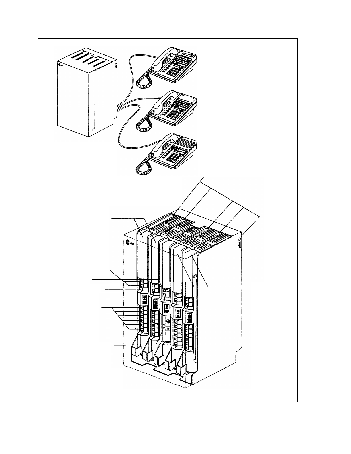
PARTNER Display Phone
(MLS-12D)
Control Unit
206 modules
Outside line jacks
PARTNER 12-Button Phone
(MLS-12)
PARTNER 6-Button Phone
(MLS-6)
Circuit Breakers
Processor
module
Paging jack
Power indicators
Extension jacks
RCA Music-on-Hold
jack
Inside the Control Unit
Figure 1-1 Basic PARTNER Plus System
1-4 Overview
206 modules
Page 13

Optional Equipment
The PARTNER Plus system works with many telecommunications devices, not
only PARTNER telephones. You can connect these other devices without having
to invest in more lines, expensive adapters, or circuit cards.
Industry Standard Devices
Many types of industry-standard telecommunications devices will work with your
PARTNER Plus system. They include:
■
Touch-tone and rotary telephones
■
Cordless telephones
■
Fax machines
■
Answering machines
■
Modems
■
Credit card verification terminals
Limitations
Connecting and Using
Standard Devices
You can connect the above devices to your system regardless of the manufacturer. However, the following limitations apply:
■
It must be a single-line device.
■
It must be industry standard. That is, it cannot be made specifically for use
on a particular telephone system. (For example, you cannot connect an
AT&T MERLIN® phone because it is specifically designed for use on a MERLIN system.)
■
The device’s Ringer Equivalence Number (REN) cannot be greater than 2.
For more information on RENs, refer to the section “Hardware” of chapter 1
in the Installation and Programming Guide.
You can connect the standard device so that it is on an extension by itself, or it
can share an extension with another piece of equipment (either another standard device or a PARTNER phone). T
O
connect two devices on one extension,
you will need an inexpensive AT&T 267F2 bridging adapter, two of which are
provided free with each 206 module. In addition, the total RENs for both devices must not exceed 2. See the Installation and Programming Guide (figure
2-3) for installation instructions.
For information on using standard devices with your PARTNER Plus system, see
chapter 6 and chapter 7 in this guide.
Overview 1-5
Page 14

Other Devices
Y
OU
can also connect other devices to your system, but only specific models are
compatible with the PARTNER Plus system. These devices include:
■
Loudspeaker paging systems
■
Doorphones
■
Headsets
■
Extra alerts (such as chimes or loud bells)
Connecting and Using Other Devices
Ordering Information
For instructions on connecting these devices to your system, see chapter 2 in
the Installation and Programming Guide.
For information on how to use your loudspeaker paging system with the
PARTNER Plus system, see chapter 4 in this guide. For information on using
doorphones, headsets, and extra alerts, follow the manufacturer’s instructions.
Optional equipment is available from many AT&T sources. Contact any of the
following for sales information and advice on the equipment that would best
meet your needs.
AT&T Catalog Sales
1 800 451-2100
AT&T General Business Systems Sales Office 1 800 247-7000
AT&T PhoneCenter Store
1 800 222-3111
AT8tT Authorized Dealer 1 800 247-1212
1-6 Overview
Page 15

Basic Call Handling
with PARTNER Phones
2
2-i
Page 16

PARTNER Phone Controls
Figure 2-1 Shows the buttons and displays on the PARTNER display telephone.
MLS Telephone Controls and Indicators
Display
[MLS-12D only]
Shows date and time (when idle) and the number
being dialed. During a call, shows the duration of
the call. When in program mode, shows progmnming options.
Dual-Purpose
Line/Programmable
Buttons
[MLS-6 has 4 buttons instead of 8]
When connected to an outside line, press to place
and receive calls. When not connected to an outside line, button can be programmed to store
dialing sequences or dial code features. An MLS6 with 4 outside lines has no programmable buttons.
Intercom
Press either button to place an intercorn (inside)
call to another extension.
Feature
Press to enter program mode or use dial code
features.
Conf (Conference)
Press to add other parties to your call.
Transfer
Press to transfer a call to another extension.
Hold
Press to put a call on hold for later retrieval.
Programmable Buttons
(2 with lights)
[MLS-12D and MLS-12 only]
Can be programmed with dial code features or
dialing sequences, according 10 needs of user.
Spkr (Speaker) Button
Tumson Speaker so you can dial or monitor a call
without lifting the handset. See in this chapter,
"Using the Speaker and Microphone.”
Mic (Microphone) Button
[MLS-12D and MLS-12 only]
Press to talk without lifting the handset. See in this
chapter, "Using the Speaker and Microphone.”
Message Indicator
Indicator lights when someone signals you with
the Message Light On feature. See “Dial Code
Features” in Chapter 3.
Volume Control Buttons
Press to increase ( ▲ ) or decrease ( ▼ ) the volume
of the ringer, speaker, and handset
❑
To adjust ringer volume, while phone is idle and
handsets on the phone, press ▲ or
❑
To adjust speaker volume, while on a call press
Spkr then press
▲
or ▼ while listening through
▼
.
Figure 2-1 PARTNER Telephone Controls
❑
To adjust handset volume, while on a call lift
handset and press
Basic Call Handling with PARTNER Telephones
▲
or ▼ while listening.
2-1
Page 17

Lights
These light patterns apply only
for buttons that have lines
assigned to them. Lights for
unused buttons are always off.
Light patterns are different when
the phone is in program mode.
There is a green and a red light next to each line button. These lights work in
different ways to show calling activity on each line. Green lights indicate activity
at your extension; red lights indicate activity at other extensions. The various
light patterns are shown below.
■
Steady On
A steady on light signifies a busy line. When the green light is on, your
extension is busy on that line. When the red light is on, someone at another
extension is busy on that line.
■
Off
(off continuously)
An off light signifies an idle line, or an unused button.
■
Flash
A flash pattern (long off, long on) signifies a ringing call. When the green
light flashes, a call is ringing on that line at your extension. When the red
light flashes, it means that the line is ringing, but not at your extension.
■
Wink
A wink pattern (long on, short off) signifies a call on hold. When the green
light winks, a call is on hold at your extension. When the red light winks, a
call is on hold at another extension.
■
Flutter
A flutter pattern (short on, short off) signifies a call on Exclusive Hold (only
you can retrieve the call). When the green light flutters, a call is on Exclusive
Hold at your extension.
■
Broken Flutter
A broken flutter (short on and off followed by long off) signifies fax trouble
when the button is programmed as a Fax Management Button (see “Fax
Management Button” in chapter 7).
■
Alternate Red/Green Flash
An alternating red and green flash (red on, green on, red on, green on)
appears on both extensions on a joined call. It also appears on an extension
connected in a conference call.
These light pattern definitions are used throughout this guide.
2-2
Basic Call Handling with PARTNER Telephones
Page 18

Using the Speaker and Microphone
Every PARTNER telephone has a speaker, which you can turn on by pressing
[Spkr]
. The PARTNER display phone and the PARTNER 12-button telephone
also have a microphone, which you can turn on by pressing
green light next to the button is on, the speaker or microphone is on.
On PARTNER phones that have a speaker and a microphone, you can make
and answer calls without lifting the handset by turning both the speaker and the
microphone on. When you turn on the speaker, you will hear a dial tone. Turning the speaker on and off is the same as lifting and replacing the handset.
On PARTNER phones that have a speaker only, you can turn on the speaker to
get a dial tone, dial the call, and hear the call ringing. When the other party
answers, you must lift the handset to talk.
You can switch from the handset to the speaker and microphone by pressing
[Spkr]
and
[Mic]
and hanging up the handset. To go from the speaker and micro-
phone to the handset, lift the handset.
[Mic]
. When the
Hands-Free Answer
on Intercom (HFAI)
This feature allows you to automatically answer a voice-signaled intercom call.
If you leave the microphone on all the time, you can respond to a voice-signaled
intercom call without lifting the handset. The incoming voice-signaled intercom
call will automatically turn on your speaker. This is called Hands-Free Answer
on Intercom. If the microphone is on and an outside call comes in, press
[Spkr]
to answer the call.
Basic Call Handling with PARTNER Telephones
2-3
Page 19

Basic Call Handling
As soon as your system is installed and programmed, you can make and handle
basic calls as described in this section. Basic call handling involves using the
buttons on the PARTNER phone that are permanently labeled, such as
[Conf]
,
[Transfer]
and
[Intercom]
.
[Hold]
,
For instructions on how to handle calls using standard rotary and touch-tone
phones, see chapter 6.
Using the Handset
or the Speaker
A Word About
Dial Tones
The procedures in this section direct you to use the handset to make and
answer calls. However, if you prefer to dial and conduct calls without lifting the
handset, you can use the speaker and the microphone instead. If you have a
PARTNER display phone or a PARTNER 12-button telephone, leave the microphone on all the time. When you want to make or answer a call (or when the
instructions direct you to “Lift the handset,”) simply press
[Spkr]
. If you receive
a voice-signaled intercom call while your microphone is on, you will hear the
caller’s voice and be able to respond without lifting the handset or turning the
speaker on. For more detail on speakerphone operation, see “Using the
Speaker and Microphone” in this chapter.
You will encounter two different dial tones when making calls with the PARTNER
Plus system.
■
Outside dial tone.
Generated by your local phone company, indicates that
you are connected with an outside line.
■
Intercom dial tone.
Generated by the PARTNER Plus system, indicates that
you are connected with an inside line. Used to make inside, or intercom,
calls.
To hear the difference between the two types of dial tones, press a line button.
The dial tone you hear is an outside line dial tone. To hear an intercom dial
tone, press either
[Intercom]
button.
2-4
Basic Call Handling with PARTNER Telephones
Page 20

Making an Outside Call
To make an outside call:
If you lift the handset before
pressing a line button, you will be
automatically connected to the
first idle line. The sequence of
idle lines to which you are connected is determined by the
Automatic Line Selection procedure. See chapter 4 in the
Installation and Programming
Guide.
If an outside line you want to use is busy (steady red light), you can reserve it so
that when the line becomes free you can make your call on it. Simply press the
busy line button without lifting the handset or touching the
the line is free, your phone will beep. Then lift the handset and dial the number.
This Line Reserve feature is useful when you have to share a line—such as a
WATS Iine—with coworkers.
If more than one person reserves a line, each phone on which the line is
reserved beeps when the line is free. The first person to pick up the phone is
connected to the reserved line; all other reservations for the line are canceled.
Feature Hints
1. Press any idle line button. (An idle line button is one that is unlit.)
The light next to the line button is steady green.
2. Lift the handset.
3. Dial the number.
On a PARTNER display telephone, the dialed number appears on the display and
the call timer begins.
[Spkr]
button. When
■
System Speed Dial.
Allows you to store up to 60 outside numbers that all
system users can dial with a few button presses. See chapter 4.
■
Personal Speed Dial.
Allows each user to store up to 20 outside numbers
that can be dialed with a few button presses. See “Quick Dialing” in chapter
3.
■
Auto Dial.
Allows each user to dial a number with a single touch by storing
the number on a button. See “Quick Dialing” in chapter 3.
■
Last Number Redial.
All users can redial the last dialed number by pressing a few buttons. Or, by programming Last Number Redial on a button, you
can redial a number by pressing the button. See “Dial Code Features” in
chapter 3.
■
Line Assignment.
You can create private lines (such as a “boss’s line”), or
regulate outgoing calls by assigning specific lines to specific telephones.
See chapter 3 in the Installation and Programming Guide.
■
Outgoing Call Restriction.
You can reduce your phone bills by preventing
callers from making specific kinds of outside calls. See “Call Restrictions
and Permissions” in chapter 4.
Basic Call Handling with PARTNER Telephones
2-5
Page 21

Making an Intercom Call
An intercom call, or inside call, is a call between two extensions in the PARTNER
Plus system.
nal the extension you are calling: by ringing or by voice. A ringing intercom call
causes the called telephone to ring, whereas a voice-signaled call causes the
caller’s voice to be heard on the called telephone’s speaker.
To make a ringing intercom call:
1. Lift the handset.
When you make an intercom call, there are two ways you can sig-
You can only voice-signal a
PARTNER phone.
2. Press an idle
You hear the intercom dial tone, and the light next to the Intercom button is green
steady.
[Intercom]
button.
3. Dial the 2-digit extension number.
To make a voice-signaled intercom call:
1. Lift the handset.
2. Press an idle
You hear the intercom dial tone, and the light next to the Intercom button is green
steady.
3. Press
busy, it will ring instead.
[ ✲ ]
Your voice is heard on the other extension’s speaker. If the other extension is
[Intercom]
button.
and the 2-digit extension number. Speak into the handset.
Feature Hints
■
Auto Dial.
by storing the number on a button. See “Quick Dial” in chapter 3.
■
Calling Group.
once. For example, if you need to talk to anyone in the sales group, you can
call all the phones in the group at the same time. See chapter 4.
Allows each user to dial an intercom number with a single touch
Anyone can ring or voice-signal a group of extensions at
■
Hotline.
lifts the receiver at a Hotline telephone, an intercom call is automatically
made to another specified extension. See chapter 4.
■
Loudspeaker Paging.
large area if you have a paging system connected to your PARTNER Plus
system. See chapter 4.
2-6
Basic Call Handling with PARTNER Telephones
You can set up a standard telephone as a Hotline. When anyone
This allows you to broadcast an announcement over a
Page 22

Answering a Call
If a call comes in on a line that
has been programmed for
“delayed ring” or “no ring, ” or if
the Do Not Disturb feature is
turned on, the call will appear as
a flashing red light, but will not
audibly ring. To answer the call,
press the line button and lift the
handset.
To answer a call:
When the telephone is ringing. . .
1. Lift the handset.
You are connected to the incoming call. If more than one line is ringing, you are
connected to the line that has been ringing longest.
If the call is an intercom call and you have a PARTNER display phone, the caller’s
extension number will briefly appear on your display.
To answer a call ringing on a specific line (when more than one line is ring-
ing):
1. Press the line button for the line you want to answer.
2. Lift the handset.
You are connected to the incoming call.
The procedure below describes how to answer a call ringing at another extension. Note that the call ringing at the other extension can be any type of call,
including a transferred call, or an intercom call. It can even be a call on a line
not assigned to your extension.
To answer a call ringing at another extension:
Ringing Patterns
A transferred call will ring like an
intercom call (ring BEEP) until the
person transferring the call hangs
up, at which time the call will ring
like a transferred call (ring BEEP
BEEP).
1. Lift the handset.
2. Press
3. Dial
[Intercom]
[6]
plus the 2-digit number of the extension that is ringing.
You are connected to the incoming call.
.
You can tell what kind of call you are receiving by the way your telephone rings.
■
A single ring (ring. . . ring. . . ring. . .) signifies an outside call.
■
A ring and a beep (ring BEEP. . . ring BEEP. . . ring BEEP . . .) signifies an
intercom call.
■
A ring and two beeps (ring BEEP BEEP. . . ring BEEP BEEP. . .
ring BEEP BEEP. .
.) signifies either a transferred call, or a transferred call
that was not answered and is ringing back.
Standard rotary and touch-tone phones ring differently. See chapter 6.
Basic Call Handling with PARTNER Telephones
2-7
Page 23

Feature Hints
■
Do Not Disturb.
telephone calls, you can stop calls from ringing at your extension. See “Dial
Code Features” in chapter 3.
■
Abbreviated Ringing.
while you are on another call. See chapter 3 in the Installation and Programming Guide.
■
Pickup Group.
group of phones, or if people in a group have to answer each other’s
phones, a call ringing at any extension can be answered from any other
extension by dialing a code. This feature is useful when calls often ring at
unattended telephones. See chapter 4.
■
Line Ringing Options.
no ring at all. For example, if a boss and a secretary share the same line
and the boss wants the secretary to answer the line first, the boss’s phone is
set to delayed ring. When the secretary is not there to answer a call, the call
will eventually ring at the boss’s phone. See chapter 4 in the Installation and
Programming Guide.
■
Night Service.
business hours while changing which phones ring on incoming calls. See
chapter 4.
When you need quiet or do not want to be interrupted by
You can program an extension to only ring once
If one person is responsible for answering calls to a certain
You can program a phone to have a delayed ring or
You can prevent unauthorized use of phones after regular
2-8
Basic Call Handling with PARTNER Telephones
Page 24

Putting a Call on Hold
There are two types of hold: Hold and Exclusive Hold. Any extension can
retrieve a call on Hold as long as it has access to the line on which it is held. A
call on Exclusive Hold can only be retrieved at the telephone at which it is held.
You can put both outside calls and intercom calls on Hold. Note, however, that
a held intercom call is always on Exclusive Hold.
To put an outside or intercom call on Hold:
1. Press
[Hold]
.
The light next to the line button winks green.
To put an outside call on Exclusive Hold:
1. Press
The light next to the line button flutters green.
[Feature] [0] [2]
.
To retrieve a call from either type of hold:
1. Press the line button on which the call is held. (For a call on Exclusive
Hold, you must beat your own phone.)
The light next to the line button changes from winking or fluttering to steady
green.
Notes
■
A user is free to make and receive other calls while a call is on hold.
■
If a call is left on hold for longer than one minute, the extension at which the
call is held generates a short Hold Reminder Tone. The reminder tone is
sounded once every minute until the held call is retrieved, or until the caller
hangs up.
■
Only one party on an intercom call can put the call on hold. If both parties
try to put the call on Hold, the call will be disconnected.
Feature Hints
■
Exclusive Hold Button.
gram a button to do it with a single touch. See “Dial Code Features” in
chapter 3.
■
Music On Hold.
You can provide music or news to outside callers on hold.
See chapter 2 in the Installation and Programming Guide for instructions on
how to connect a stereo or other audio source.
If you put calls on Exclusive Hold frequently, pro-
Basic Call Handling with PARTNER Telephones
2-9
Page 25

Transferring a Call
To transfer a call means to pass the call from one extension to another. You can
transfer both outside calls and intercom calls.
A transferred call will ring like an
intercom call (ring BEEP) until the
person transferring the call hangs
up, at which time the call will ring
like a transferred call (ring BEEP
BEEP).
You can only announce a call
through the speaker of a
PARTNER phone. If it is busy, or
if it is a standard phone, it will
ring instead.
There are three ways to transfer a call:
■
You can announce the call when it is picked up.
■
You can announce the call through the speaker.
■
You can transfer the call with no announcement.
To transfer a call with an announcement over the handset:
1. While active on a call, press
You hear the intercom dial tone. The call is put on Hold and its associated light
winks green.
[Transfer]
.
2. Dial the 2-digit number of the extension to which you want the call
transferred.
3. When someone answers, announce the call. If the call is accepted, hang
up. If no one answers or the call is refused, press the held line button next
to the winking light and you are reconnected with the caller.
To transfer a call with announcement over speaker:
1. While active on a call, press
You hear the intercom dial tone. The call is put on Hold and its associated light
winks green.
2. Dial
[ ✳ ]
plus the 2-digit number of the extension to which you want the call
[Transfer]
.
transferred.
3. Announce the call.
The other party’s speaker is automatically turned on, and your voice is heard on it.
The other party can pick up the call by pressing [Mic]
4. If you hang up and the party does not pickup the call, the call will ring
back at your phone. Press the held line button next to the winking light (or
press the lit
2-10
Basic Call Handling with PARTNER Telephones
[Intercom]
or lifting the handset.
button), and you are reconnected with the caller.
Page 26

To transfer a call with no announcement:
1. While active on a call, press [Transfer] .
You hear the intercom dial tone. The call is put on Hold.
2. Dial the 2-digit number of the extension to which you want the call
transferred.
3. Hang up.
If no one answers, the call will ring back at your extension.
Feature Hints
Another way to transfer an out-
side call is to put it on Hold, and
then have another user pick the
call up at another extension by
pressing the line button (they see
it as winking red) of the held call.
■
One Touch Transfer.
If you program an intercom number onto a button, you
can transfer calls to that extension simply by pressing the button. See
“Quick Dialing Features” in chapter 3.
Notes
■
You cannot transfer calls to the Calling Group (see page 4-7).
■
When you transfer a call to another extension from a PARTNER display
phone, the extension number you transfer the call to briefly appears on the
display. If that extension does not pickup within a certain number of rings,
the call will ring back at your phone with the transfer ring pattern, and the
extension number will again briefly appear on the display.
Your system is set at the factory to return a transferred call after it rings four
times. You can change this number if you need to. See “Transfer Return
Rings” in the Installation and Programming Guide, chapter 3.
Basic Call Handling with PARTNER Telephones
2-11
Page 27

Making a Conference Call
A conference call connects up to five parties (including the conference originator) in a single call. You can connect both outside calls and intercom calls in a
conference call; however, the call cannot include more than two outside parties.
During the conference call, any inside party can exit the call at any time simply
by hanging up. However, if an outside party hangs up during a conference call,
the callers that remain on the conference will hear a dial tone. A PARTNER Plus
system feature called Conference Drop removes the last added outside party
from a conference call. Therefore, when setting up a conference call, plan carefully. If you have two outside parties on a conference call, and you think that
one of those parties may exit the call before the other, add that party last so that
you can remove it using Conference Drop while maintaining the connection with
the other parties.
The conference originator can put his or her end of the call on Hold during the
conference. Other parties can continue to talk while the call originator is on
Hold. Other inside parties cannot put their extensions on Hold. When the
conference originator hangs up, the conference is disconnected.
To setup a conference call:
1.
Set up the call to the first party. (Y
from Hold, or answer an incoming call.)
You are connected with the first party.
OU
can call the party, or pick up the call
If you are adding an intercom
extension to a call, you must wait
until the party answers before
you press
[Cont] to add the party.
2.
Press
3.
Set up the call to the second party.
4.
Press
You can now speak with the first and second parties.
Return to step 2 to add one or two more parties.
5.
[Conf]
.
The first party is now on Hold.
You are connected with the second party.
[Conf]
again.
To drop the last added outside call from a conference call:
1. Press
The outside call is dropped.
[Feature] [0] [6]
.
Notes
■
You can use System Speed Dial, Personal Speed Dial, or Auto Dial numbers
to add calls to the conference.
■
You should not add a busy or ringing outside call to a conference; if you do,
all callers will hear the busy or ringing signal. If you hear a busy signal or the
2-12
Basic Call Handling with PARTNER Telephones
Page 28

party does not answer, reconnect with the held party by pressing the line
button.
■
You cannot transfer a conference call.
You cannot join a conference call. That is, the conference initiator must add
■
each party to the conference.
■
You cannot add outside calls to a conference call if your system is pro-
grammed for Outside Conference Denial. See chapter 3 in the Installation
and Programming Guide.
Feature Hints
■
Conference Drop.
gram the Conference Drop feature onto a button. See “Dial Code Features”
in chapter 3.
■
Quick Dialing.
the conference call. See chapter 3.
If you make conference calls frequently, you can pro-
You can use Speed Dialing or Auto Dialing to add parties to
Basic Call Handling with PARTNER Telephones 2-13
Page 29

Joining a Call
One extension can connect itself to an outside call at another extension by joining. For example, if John is on an outside call and wants you to participate in
that call, you can join in by pressing the line button of the line on which the call
is being conducted. You cannot join an intercom call, and you can only join a
call on a line that is assigned to your extension.
To join a call:
A steady red light at a line button indicates a call in progress. . .
1. Press the line button.
2. Lift the handset to speak.
The red and green lights alternately flash. You are now joined with the call.
Notes
■
You can tell when someone has joined your call when the steady green light
next to the line button changes to an alternately flashing red and green light.
■
Do not confuse joining with conferencing. In joining, you add yourself to a
call in progress in the same way you would on a home telephone by picking
up an extension. In conferencing, the call originator calls you in the process
of setting up the call.
■
You cannot put a joined call on hold.
■
If you call an outside line, up to three PARTNER extensions can join you on
the call (for a total of one outside caller and four inside parties).
Feature Hints
■
Privacy.
from joining a call on your telephone. Any user can program Privacy onto a
button so that it can be turned on and off as needed. See “Dial Code
Features” in chapter 3.
■
Automatic Privacy.
specific extension. This is typically used for answering machines, fax
machines, modems, and credit card verification terminals, because trying to
join one of these devices could interfere with its operation. See chapter 3 in
the Installation and Programming Guide.
Can be turned on and off as needed to prevent other extensions
Prevents other extensions from joining calls on a
2-14
Basic Call Handling with PARTNER Telephones
Page 30

User-Programmable Features
3
3-i
Page 31

The user-programmable features described in this chapter are those features
that anyone on the PARTNER Plus system can use at his or her telephone.
User-programmable features are divided into two groups:
■
Dial Code Features.
Used to handle calls more quickly and efficiently, to
customize a PARTNER phone for an individual user’s needs, or to activate
certain capabilities of the PARTNER Plus system.
■
Quick Dialing Features.
Spare you from constantly having to look up long
telephone numbers by allowing you to dial those numbers with three button
presses or fewer.
User-Programmable Features
3-1
Page 32

Dial Code Features
Two dial code features, Do Not
Disturb and Privacy, must be
programmed onto a button with a
light.
There are 10 dial code features. Table 3-1 lists each dial code feature, what the
feature does, and how to use it.
If there are certain dial code features that someone uses often, he or she can
program those features onto a programmable button. This allows the feature to
be activated or turned on and off with a single touch. All dial code features can
be programmed onto a button. Since there are more features than buttons,
each person should decide which features are most useful to him or her before
assigning them to a button.
Immediately following table 3-1 are instructions on how to program a dial code
feature onto a button.
3-2
User-Programmable Features
Page 33

Table 3-1 Dial Code Features
Feature
Do Not Disturb
Exclusive Hold
Recall
What It Does
Prevents your phone
from ringing. Outside
callers hear ringing;
intercom callers hear a
busy signal. If you
transfer a call and it is
not answered and
returns to you, your
phone will ring even if Do
Not Disturb is on.
Prevents any other
extension from picking
up a call you put on hold.
Gives you a dial tone
without having to press
the switchhook. (Many
PBX/Centrex features
often require a Recall
operation in order to
work. ) Recall will disconnect an intercom call.
How to Use It
This feature must be
programmed onto a but-
ton with a light. (See
instructions in this
chapter.) Use button
like a switch—when the
light is on, Do Not Dis-
turb is on.
Press
[Feature] [0] [2]
, or
the programmed button,
to hold call. Retrieve the
call by pressing the line
button on which the call
is held.
Press
[Feature] [0] [3]
or
the programmed button.
Dial Code
01
02
03
Save Number Redial
Last Number Redial
Saves the most recently
dialed outside number
(maximum 20 digits per
phone number). After it
is saved, the number can
be redialed any time until
you save a different
number. Allows you to
make calls before redialing a number.
Redials the last outside
number dialed (maximum 20 digits per
phone number). Good
for redialing a busy
number.
To save a number
into memory: before
hanging upon the
outside call, press
[Feature] [0] [4] or the
programmed button.
To redial the saved
number: lift the
handset, then press
[Feature] [0] [4]
, or
the programmed
button.
Lift the handset and
press
[Feature] [0] [5]
, or
press the programmed
button.
04
05
.
User-Programmable Features
3-3
Page 34
Table 3-1 Dial Code Features (cont.)
Feature
Conference Drop
What It Does
Drops the last added
outside party from a
conference call without
disconnecting the
other parties.
How to Use It
Press [Feature] [0] [6] or
the programmed but-
ton.
Dial Code
06
Privacy
Touch-Tone Enable
Message Light On
Prevents other extensions who share lines
This feature must be
programmed onto a
with you from joining a button with a light.
call on your phone. (If
Automatic Privacy—a
system programming
Use the button like a
switch; when the light
is on, Privacy is on.
procedure—is pro
grammed for an extension, using Privacy will
override it.)
Sends touch-tone signals over the line.
Good for services that
require touch-tone
digits, such as tele-
Press
the programmed button, at the point in the
call when you need
touch-tone signals.
[Feature] [0] [8]
phone banking, pag- Touch-Tone Enable
ing, and automatic
stays on for the rest of
answering. the call.
Turns on the Message
light on another
PARTNER phone.
Although anyone can
use this feature, it is
typically used by a
Press
[Feature] [0] [9]
or the programmed
button, then dial the
extension number or
press an Intercom
Auto Dial button.
receptionist to let
someone know a message is waiting.
,
or
07
08
09
Message Light Off
3-4
User-Programmable Features
Turn off a previously lit
Message light.
Press
[Feature] [1] [0]
,
or the programmed
button, then dial the
extension number or
press an Intercom
Auto Dial button.
10
Page 35

Programming Dial Code Features onto Buttons
Any user can program a dial code feature onto a button at his or her own phone.
Or, you can program other users’ telephones for them by working from extension 10. For instructions on how to do this, see chapter 4 in the Installation and
Programming Guide.
Note that a PARTNER 6-button telephone with 4 outside lines assigned to it has
no programmable buttons. However, any unused line button on a PARTNER 6button phone can be used as a programmable button. In fact, any unused line
button on any PARTNER phone can be used as a programmable button.
To program a dial code feature onto a programmable button on an indivi-
You can also use this procedure
to program a new dial code
feature over another one already
assigned to a button. Simply
enter the new dial code.
dual telephone:
Press [Feature] [0] [0] .
1.
You are in program mode.
Press the button to which you want the dial code feature assigned.
2.
On a PARTNER display phone, the display shows what feature, if any, is currently
assigned to that button.
Press
3.
4.
[Feature]
Enter the dial code. (See table 3-1.) For example, to program Last
Number Redial, enter
The button is now programmed.
.
[0] [5]
.
You cannot remove a dial code
feature from a button on a
PARTNER 6-button phone. You
must do it by working from extension 10. See chapter 4 in the In-
stallation and Programming
Guide.
To program more feature buttons, repeat steps 3 and 4. To exit program
5.
mode, press [Feature] [0] [0] , or lift the handset and replace it.
To remove a dial code feature from a programmed button:
1. Press
[Feature] [0] [0]
You are now in program mode.
.
2. Press the button from which you want the dial code feature removed.
On a PARTNER display phone, the display shows what feature, if any, is currently
assigned to that button.
3. Press
[Mic]
.
4. To clear another programmed button, return to step 2. To exit program
mode, press
[Feature] [0] [0]
, or lift the handset and replace it.
User-Programmable Features
3-5
Page 36

Quick Dialing Features
Quick Dialing allows you to dial frequently called numbers by pressing three or
fewer buttons. Quick Dialing spares you from memorizing or constantly looking
up different telephone numbers. You can also use Quick Dialing to dial such
additional numbers as bank account or credit card numbers.
There are three different Quick Dialing features:
■
Each Auto Dial, Personal Speed
Dial, or System Speed Dial
number can contain up to 20
digits.
Auto Dialing.
grammable button and dial the number by pressing that button. Or, you can
program a user’s telephone from extension 10.
■
Personal Speed Dialing.
20 digits in each telephone’s memory. Each Personal Speed Dial number is
assigned a 2-digit code. The number is dialed by pressing
2-digit code. Any user can program Personal Speed Dial numbers at his or
her telephone. Or, you can program a user’s telephone from extension 10.
■
System Speed Dialing.
numbers in the system's memory that any user can dial. Each System
Speed Dial number is assigned a 2-digit code. The number is dialed by
pressing
chapter 4.)
Any user can program numbers onto a telephone’s pro-
Any user can program up to 20 numbers of up to
[Feature]
From extension 10, you can program up to 60
[Feature]
plus the 2-digit code. (System Speed Dialing is covered in
plus the
Auto Dialing
You can program a fax extension
number as an Auto Dial number
on a PARTNER phone at another
extension (the Auto Dial button
must have a light). You can then
use the Auto Dial number to
quickly transfer calls from that
extension to the fax machine. In
addition, the light on that button
shows whether the fax machine
is in use
you transferred to it, or not
answering calls. If your AT&T fax
machine includes the “Notify”
feature, the fax machine can also
notify you when a fax has been
received.
busy, returning a call
r
IMPORTANT:
When programming and/or testing emergency numbers (such
as 911 or other emergency services):
1. Remain on the line and briefly explain to the dispatcher the reason for the
call before hanging up.
2. Perform such activities during the off-peak hours, such as early morning or
late evening.
Auto Dialing allows any user to dial a number with a single touch. To use the
Auto Dial feature, you must first program the number onto a programmable button. You can program both outside numbers and intercom numbers for Auto
Dialing.
There are added benefits when you store an intercom number for Auto Dialing.
They are:
■
One Touch Transfer.
You can transfer a call to an extension simply by
pressing the Auto Dial button.
■
Intercom Status.
You can monitor the calling activity at another extension
by programming the extension onto a button with a light. The light patterns
next to the button show the activity at the extension. Table 3-2 shows what
each light pattern means.
3-6
User-Programmable Features
Page 37

Table 3-2 Light Patterns on Intercom Auto Dial Button
Light Pattern Status
steady red extension is busy or has Do Not Disturb on
green flash
green flutter
extension is calling you
a call you transferred to another extension is
returning
Since there are more features than there are programmable buttons, you should
consider using Auto Dial only for your most frequently dialed numbers, or for the
extra capabilities you get from programming an intercom number for Auto Dial.
You can also program an Auto
Dial number onto an extension
while working from extension 10.
See chapter 4 in the Installation
and Programming Guide.
You can also use this procedure
to program a new Auto Dial
number over another one already
assigned to a button. Simply
enter the new number.
You cannot remove an Auto Dial
number from a button on a
PARTNER 6-button phone. You
must do it by working from extension 10. See chapter 4 in the In-
stallation and Programming
Guide.
To program an Auto Dial number (at any extension):
1. Press
[Feature] [0] [0]
You are now in program mode.
.
2. Press the programmable button to which you want the number assigned.
3. To program an intercom number, press the left
[Intercom]
button and dial the
extension number. To program an outside number, dial the number. If you
want to insert special functions into an outside number or numeric
sequence, such as Pause, Stop, Touch-Tone Enable, or Recall, see “Pro
gramming Special Functions Into a Telephone Number” in this chapter.
4. To program another button, return to step 2. To leave program mode,
press
[Feature] [0] [0]
You are now out of program mode. The Auto Dial number is stored and ready to
use.
, or lift the handset and replace it.
To remove an Auto Dial number from a programmable button:
Press
1.
2.
[Feature] [0] [0]
You are now in program mode.
Press the programmable button from which you want the Auto Dial number
.
removed.
On a PARTNER display telephone, the display shows what number, if any, is
currently assigned to that button.
Press
[Mic]
3.
4.
To clear another programmable button, return to step 2. To exit program
mode, press
.
[Feature] [0] [0]
, or lift the handset and replace it.
User-Programmable Features
3-7
Page 38

You can dial an Auto Dial number
To dial an Auto Dial number:
while on an outside call. For
example, you can do this to dial
an account number for an
automatic banking service. However, you cannot dial an Auto Dial
number while on an intercom call.
If you want to call on a specific line, press the line button before pressing the
Auto Dial button.
Personal Speed Dialing
Personal Speed Dialing allows anyone to store up to 20 numbers that can be
dialed with only three button presses. (This is different from Auto Dialing, which
allows you to dial a number with a single button press.) Personal Speed Dial
numbers are stored into memory and assigned a 2-digit code from 80 through
99. To dial the number, press
number. Only outside numbers can be stored for Personal Speed Dialing.
Personal Speed Dialing is used for those personal numbers that are dialed fre-
quently, but not frequently enough to be programmed onto a button as an Auto
Dial number. The Quick Reference Card has a form on which each user can
record Personal Speed Dial numbers.
1. Press the programmable button on which the Auto Dial number is programmed.
A line is automatically selected, the speaker comes on, and the Auto Dial number
dials automatically.
[Feature]
plus the 2-digit code associated with the
You can use this procedure to
program a Personal Speed Dial
number over another one without
first c/earing the old number.
Simply enter the new number.
To program a Personal Speed Dial number:
Press [Feature] [0] [0] .
1.
You are now in program mode.
2.
Press
[Feature]
and then press the 2-digit number between 80 and 99 that
you want to assign to the Personal Speed Dial number.
Enter the number, up to 20 digits long. (If you want to include special
3.
functions into the number, such as Pause, Stop, Touch-Tone Enable, or
Recall, see “Programming Special Functions into a Telephone Number” in
this chapter.
4.
To program another Personal Speed Dial number, return to step 2. To
leave program mode, press
[Feature] [0] [0]
, or lift the handset and replace
it.
You are now out of program mode. The Personal Speed Dial number is now
stored and ready to use.
3-8
User-Programmable Features
Page 39

You cannot remove a Personal
Speed Dial number while working
from a PARTNER 6-button phone.
You must do it by working from
extension 10. See chapter 4 in
the Installation and Programming
Guide.
To remove a Personal Speed DiaI number from memory:
1. Press [Feature] [0] [0] .
You are now in program mode.
2. Press
[Feature]
and then press the 2-digit code of the Personal Speed Dial
number you want to remove.
3. Press
[Mic]
.
4. To remove another number, return to step 2. To leave program mode,
press
[Feature] [0] [0]
, or lift the handset and replace it.
You can dial a Personal Speed
Dial number while on an outside
call. For example, you can do
this to dial an account number for
an automatic banking service.
However, you cannot dial a Personal Speed Dial number while
on an intercom call.
To dial a Personal Speed Dial number:
1. Press
[Feature]
code.
A line is automatically selected, the speaker comes on, and the Personal Speed
Dial number dials automatically.
If you want to call on a specific line, press the line button before pressing
[Feature] .
.
and then press the 2-digit Personal Speed Dial number
Programming Special Functions into a Telephone Number
Table 3-3 (p. 3-10) lists certain actions you can program into any Quick Dial
number that give it added capabilities for special situations.
User-Programmable Features
3-9
Page 40

Table 3-3 Special Dialing Functions
Function Button
Pause
[Hold]
Display
P
Inserts a 1.5-second pause in the dialing sequence to wait
for a response, such as a dial tone or computer voice message.
Example:
4.5 seconds, then dial 321 to retrieve messages, enter
[5] [5] [5] [0] [5] [2] [9] [Hold] [Hold] [Hold] [3] [2] [1] .
Description and Example
To
call an answering machine at 555-0529, wait
Recall
Stop
[Spkr]
[Mic]
R
Sends a timed switchhook flash needed to alert the system
on the other end (such as a PBX or Centrex), and to use
some local telephone company custom calling features
(such as Call Waiting). Use Recall only as the first entry in
a speed dial number.
Example:
To use a favorite Centrex feature, you have to
send a timed switchhook flash and then dial 388. Enter
[Spkr] [3] [8] [8] .
S
Stops the dialing sequence so the user can enter additional digits, such as a credit card number or password.
Press
Note:
[Feature]
Since PARTNER 6-button phones have no
and the 2-digit speed dial code to continue.
[Mic]
button, the Stop dialing function is not available on those
phones.
Example:
Your local bank-by-phone service requires you
to enter a password before the account number. To program a marked speed dial number to call the bank at 5557898, include a stop for manually entering the password,
and continue with the bank account number (679 556 88),
enter [ ✳ ] [5] [5] [5] [7] [8] [9] [8] [Mic] [6] [7] [9] [5] [5] [6]
[8] [8]
. Marking the phone number prevents the account
number from being displayed when users dial it.
Touch-Tone
[Transfer]
Enable
3-10 User-Programmable Features
T
Sends touch tones over a rotary line to electronic equip-
ment such as answering machines and bank computers.
Example:
Your system is connected to rotary lines but
you want to tail an answering machine at 555-3454 to
retrieve messages. Since the answering machine requires
touch tones, enter [5] [5] [5] [3] [4] [5] [4] [Transfer] . All
digits pressed during the rest of the call are sent as touch
tones.
Page 41

System Features
4
4-i
Page 42

System Speed Dialing
System features affect the operation of the entire system and can be
programmed only at extension 10. These features are normally programmed
when the system is installed. However, you may from time to time have need to
change, remove, or reinstate them. For complete instructions on system
programming procedures, see chapter 3 in the Installation and Programming
Guide.
Do not confuse the System
Speed Dial feature with Personal
Speed Dial, which allows each
user to create an individual list of
speed dial numbers.
You can use this procedure to
program a System Speed Dial
number over another one without
first clearing the old number.
Simply enter the new number.
Marked System Speed Dial
numbers cannot contain a Recall
character. (See “Programming
Special Functions into a
Telephone Number” in chapter 3
for more in formation.)
System Speed Dialing allows you to program phone numbers that any user can
dial by pressing only three buttons. System Speed Dial numbers are typically
numbers that users may often need to dial, such as suppliers, repair services,
customers, or other business associates. You can store up to 60 System Speed
Dial numbers of up to 20 digits each. Each System Speed Dial number is
assigned a 2-digit code from 20 through 79.
You can designate System Speed Dial numbers to override all call restrictions
except those imposed by Line Use Restriction (#302). (See “Call Restrictions
and Permissions” in this chapter for more information.) These specially
designated numbers are called Marked System Speed Dial Numbers.
Appendix A in this guide provides a form on which to record System Speed Dial
numbers. Please give a photocopy to each user.
To program a System Speed Dial number (from extension 10):
Press [Feature] [0] [0] .
1.
You are now in program mode.
2.
Press
[Feature]
and then dial the 2-digit code (20 through 79) you want
assigned to the System Speed Dial number.
Enter the System Speed Dial number (up to 20 digits). If you want the
3.
number to override call restrictions, enter a
[ ✳ ]
in front of the number. (If
you want to insert special functions into the number, such as Pause, Stop,
Touch-Tone Enable, or Recall, see “Programming Special Functions into a
Telephone Number” in chapter 3.)
4.
To program another Speed Dial number, return to step 2. To leave
program mode, press
You are now out of program mode. The System Speed Dial number is stored and
ready to use.
[Feature] [0] [0]
, or lift the handset and replace it.
IMPORTANT:
When programming and/or testing emergency numbers (such
as 911 or other emergency services):
1. Remain on the line and briefly explain to the dispatcher the reason for the
call before hanging up.
2. Perform such activities during the off-peak hours, such as early morning or
late evening.
.
System Features 4-1
Page 43

You cannot remove a System
Speed Dial number while working
from a PARTNER 6-button phone.
You must do it by working from
extension 10. See chapter 4 in
the Installation and Programming
Guide.
To remove a System Speed Dial number from memory:
1. Press
You are now in program mode.
2. Press
[Feature] [0] [0]
[Feature]
and then dial the 2-digit System Speed Dial code of the
.
number you want to remove.
3. Press
[Mic]
.
4. To delete another number, return to step 2. To leave program mode,
press
[Feature] [0] [0]
, or lift the handset and replace it.
To dial a System Speed Dial number (from any extension):
1. Lift the handset.
2. Press
[Feature]
The phone number dials automatically.
and press the 2-digit System Speed Dial code.
Dialing Restrictions and Permissions
The PARTNER Plus system has several programmable procedures that are used
to restrict telephone use, and several that are used to to override those restrictions.* You can use any combination of these procedures to design a system
that meets your needs.
There are three basic categories of restrictions that you can program into your
All system programming procedures are identified by a # and
a 3-digit number. See chapter 3
of the Installation and Program
ming Guide for detailed instructions.
system. These are:
■
Restrictions on Lines.
specific extensions. (See “Line Use Restriction (#302),” below.)
■
Restrictions on Extensions.
sion can make. (See “Outgoing Call Restrictions (#401 ),” below.)
■
Restrictions on Numbers.
extension can dial. (See “Disallowed Phone Number List (#404 ),” below.)
You can also program an extension with the ability to override these restrictions
in several ways. See “Restriction Override Procedures, ” below. For instructions
on system programming, see chapter 3 in the Installation and Programming
Guide.
Allow you to restrict activity on specific lines at
Allow you to restrict the type of calls an exten-
Allow you to restrict what kind of numbers an
* While procedures that restrict dialing are very effective, absolute protection against misuse cannot be guaranteed.
PARTNER phones give you more protection against such misuse than standard phones. Therefore, we strongly
recommend that you install PARTNER phones where restricting phone use is important.
4-2 System Features
Page 44

Dialing Restrictions
The procedures that restrict telephone activity are:
■
Line Use Restriction (#302).
Allows you to impose incoming and outgoing
restrictions on the specific lines assigned to an extension. These restrictions
are:
■
Out only. The extension can make but not receive calls (except
transferred calls) on this line.
Example:
If part of your business involves heavy outside phone calling,
such as telemarketing or phone surveys, you can program a phone so
that all its lines are “out only.”
The phone can make outside calls, but not
receive calls, thereby preventing employees from receiving calls while
working.
■
In only. The extension can receive but not make calls on this line.
Example:
set up one or more lines for “in only.”
If part of your business involves taking phone orders, you can
Employees will be unable to make
outgoing calls on those lines, thereby keeping them open for incoming
calls.
■
No access. The extension cannot make or receive calls on this line.
However, calls can be transferred to it. The employee using this extension can also monitor calling activity on the line by looking at light indicators.
Example:
The boss may have a private line that no one else can use.
However, the boss may want his or her secretary to be able to see
whether or not he or she is busy on the phone. The secretary’s phone
could have the boss’s line assigned to it, but set for “no access.” This
would allow the secretary to see when the boss is on the phone. It would
also allow the boss to transfer a call to the secretary.
■
Outgoing Call Restriction (#401).
Defines the type of calls an extension
can make. There are two types of call restriction:
■
Intercom calls only (i.e., cannot make outside calls)
■
Local calls only (i.e., cannot make toll calls)
Once you program a restriction for an extension, it applies to all the lines on
that extension.
Example:
You can set up an extension in your lobby as a “courtesy phone”
from which visitors can make intercom calls and local calls but not toll calls.
The courtesy phone would be set for “local calls only.”
■
Disallowed Phone Number List (#404).
Creates a list of numbers that can-
not be dialed. The numbers on a disallowed list do not have to be specific;
they can be numbers of a certain length, or of a certain type, such as all
numbers in a certain area code, or all 900 numbers. You can store up to four
different lists of up to 10 numbers each. After you create the Disallowed
System Features 4-3
Page 45

Phone Number List, use the Disallowed List Assignment (#405) procedure to
assign one or more of the lists to a specific extension. When a Disallowed
Phone Number List is assigned to an extension, it applies to all the lines on
that extension.
Overriding Dialing Restrictions
Example:
Use the Disallowed Phone Number List to restrict calls to 900
entertainment numbers.
The following procedures allow an extension to override dialing restrictions
imposed by the outgoing Call Restriction (#401) procedure and the Disallowed
Phone Number List (#404) procedure. Restrictions imposed by the Line Use
Restriction (#302) procedure cannot be overridden.
■
Emergency Phone Number List (#406).
Allows you to create a list of
numbers that all extensions in the system can dial, at any time, overriding all
dialing restrictions except Line Use Restriction (#302), even when Night Service is on. It is typically used to list emergency numbers, such as doctor or
police, or service numbers suchas611. The emergency list holds up to 10
numbers.
■
Marked System Speed Dialing.
(This is not a procedure. See “System
Speed Dialing,” in this chapter.) This allows you to “mark” a system Speed
Dial number so that it can override the above-mentioned restrictions.
■
System Password (#403).
This procedure allows you to create a password
that, when entered, enables a user to override all dialing restrictions except
those imposed by Line Use Restriction (#302). See “Using the Password” in
this chapter.
Night Service
■
Allowed Phone Number List (#407).
Allows you to create a list of numbers
that an extension is allowed to dial, despite the Outgoing Call Restriction and
Disallowed Phone Number List procedures. The PARTNER Plus system
stores up to four different lists of up to 10 numbers each. After creating
allowed lists, use the Allowed List Assignment (#408) procedure to assign
one or more of the lists to a specific extension.
Example:
You have restricted outside calling. However, there are certain
business numbers, such as suppliers, repair services, etc., that your employees need to call. Place these numbers on the allowed list.
The Night Service feature allows you to change how a group of extensions
operate, usually outside of normal business hours. When Night Service is turned
on, all incoming calls will ring immediately at the extensions in the Night Service
Group. These incoming calls will override any other previously programmed
Line Ringing options (“delayed ring” or “no ring”).
In addition, if the system is programmed with a password, the extensions in the
Night Service Group are restricted from calling any outside numbers except
4-4 System Features
Page 46

Marked System Speed Dial numbers or those on the Emergency Phone Number
List. Users can, however, make an outside call if they first enter the system
password. (See “Entering the Password” in this chapter.)
Example:
Night Service is typically used in the following scenario: The system
is set up in an office where all calls normally come through a receptionist. The
receptionist goes home at 5:00 in the evening, but there are often people who
stay to work later. At 5:00, the receptionist turns on Night Service, which
causes all the phones in the Night Service Group to ring immediately when a call
comes in.
Programming your system for Night Service requires two basic steps: deciding
which extension belong in the Night Service Group, and assigning a Night Service button to extension 10. If you want to restrict outward calling while Night
Service is on, program a system password.
For detailed instructions on how to program Night Service, see the following procedures in chapter 3 of the Installation and Programming Guide:
■
Night Service Group (#504)
Night Service Button (#503)
■
■
System Password (#403)
Night
(optional)
Service button
is here
Figure 4-1 Night Service Button
System Features
4-5
Page 47

Turning On Night
Service
To turn on Night Service (without a password):
1. Press the Night Service button on extension 10.
The light is steady green. Night Service is on.
To Turn On Night Service (with a password):
1. Press the Night Service button on extension 10.
The light is flashing green.
2. Enter the password.
The light is steady green. Night Service is on.
Turning Off Night Service
Pickup Group
To Turn Off Night Service (without a password):
1. Press the Night Service button on extension 10.
The green light goes off. Night Service is off.
To Turn Off Night Service (with a password):
1. Press the Night Service button on extension 10.
The light is flashing green.
2. Enter the password.
The green light goes out. Night Service is off.
The Pickup Group feature allows you to create a group of extensions in which
any outside call can be answered from any other extension in the system by
dialing a special code. In other words, when an outside call rings in the Pickup
Group, you can answer that call from any extension by dialing a code. You can
create one Pickup Group.
The Pickup Group is typically used for a group of people who can handle each
other’s incoming calls.
Example:
A group of word processors work in a large room separated by cubicles. If any one of the word processors is away from his or her desk, anyone
else in the group can answer an incoming call without knowing whose phone is
ringing simply by pressing
[Intercom]
plus the Pickup Group dial code. Another
way to use this feature is to leave all extensions in the Pickup Group. This allows
anyone on the system to answer any ringing phone.
4-6 System Features
The PARTNER Plus system comes preset with all extensions in the Pickup
Group. If you want to customize a Pickup Group, use the Pickup Group Extensions (#501) procedure to remove extensions from the group until only those you
want in the group remain. For detailed instructions on how to program this procedure, see chapter 3 in the lnstallation and Programming Guide.
Page 48

Answering a Call to
the Pickup Group
To answer a call to the Pickup Group:
When an extension in the Pickup Group is ringing:
1. Lift the handset at any extension.
Calling Group
Making a Call to a Calling Group
You can program [Intercom] [7] [1]
onto a programmable button to
call the Calling Group with a sin-
gle touch.
2. Press
[Intercom] [6] [6]
.
The Calling Group feature allows you to make an intercom call—either ringing or
voice-signaled—to an entire group of extensions simultaneously. If one extension in the group answers the call, the ringing stops at the other extensions in
the group. You can create one Calling Group.
Example:
One way to use the Calling Group is to place all extensions in the
Calling Group. This allows anyone to make an intercom call (either ringing or
voice-signaled) that will be heard at every extension. Another way is to place
only those extensions belonging to a certain group (such as all the phones in the
sales department or warehouse) in the Calling Group. Then, if you need to talk
to anyone in that group, you can make an intercom call to the group.
The PARTNER Plus system is preset at the factory with all extensions in the Cal-
Iing Group. if you want to customize the Calling Group, use the Calling Group
(#502) procedure to remove extensions from the group until only those you want
in the group remain. For detailed instructions on how to program a Calling
Group, see chapter 3 in the Installation and Programming Guide.
To make a ringing call to the Calling Group:
1. Lift the handset and press
You hear the intercom dial tone.
2. Dial
[7] [1]
.
All available extensions in the Calling Group ring.
[Intercom]
(in either order).
To make a voice-signaled call to the Calling Group:
1. Lift the handset and press
You hear the intercom dial tone.
2. Dial
[ ✳ ] [7] [1]
.
[Intercom]
(in either order).
3. Speak into handset.
Your voice is heard through the speakers of all PARTNER telephones that are not
busy in the calling group. When the call is answered, either by someone lifting
the handset or pressing [Mic]
on the phone that answered the call.
NOTE:
You cannot transfer calls to the Calling Group.
, your voice is no longer heard on ail telephones, only
System Features 4-7
Page 49

Loudspeaker Paging
You can connect a loudspeaker paging system directly to your system without
having to buy additional jacks or phone lines. Any phone can make an
announcement over the loudspeaker paging system.
To make an announcement over the loudspeaker paging system:
Hotline
You must use a standard rotary
or touch-tone telephone for the
Hotline extension.
1. Lift the handset and press
2. Dial
[7] [0]
.
[Intercom]
(in either order).
3. If your paging system is an AT&T PagePac 6, speak into the handset.
Your voice is heard through the system.
If your paging system is an AT&T PagePac 6 Plus, dial
announcement in zone 1; dial
zones 2 and 3; dial
[7]
for all zones. Speak into the handset. Your voice is heard through the
[5]
for zones 1 and 3; dial
[2]
for zone 2; dial
[6]
for zones 1 and 2; dial
[1]
to make an
[3]
for zone 3; dial
[4]
for
system.
If you have a paging system other than a PagePac 6 or Pagepac 6 Plus
follow the manufacturer’s instructions.
The Hotline feature allows you to create a Hotline extension. Lifting the handset
on a Hotline extension automatically makes an intercom call to another predeter-
mined extension.
Example:
Many supermarkets install a Hotline phone near their meat counters.
When customers lift the handset on the Hotline phone, they automatically ring
the butcher’s phone on the other side of the glass.
For instructions on programming a Hotline, see the following procedures in
chapters 3 and 4 of the Installation and Programming Guide:
4-8
System Features
■
Hotline (#603)
■
Automatic Line Selection.
The Hotline extension’s Automatic Line Selection
must be programmed to Intercom only.
■
Line Assignment (#301).
Use this procedure to make sure that no outside
lines are assigned to the Hotline extension.
■
Calling Group Extensions (#502).
Use this procedure to remove the Hot-
Iine extension from the Calling Group.
Page 50

Using the Password
If a password has been programmed for the system, you can use the password
to override all dialing restrictions except those imposed by Line Use Restriction
(#302). You must enter the password for each call you want to make.
To program a password, use the System Password (#403) procedure. See
chapter 3 in the Installation and Programming Guide.
To enter the password:
Before lifting the handset or turning on the speaker. . .
1. Press
2. Enter the password.
3. Press an outside line button.
4. Lift the handset and dial the number.
[Hold]
.
System Features 4-9
Page 51

Changing System Settings
5
5-i
Page 52

Although your PARTNER Plus system was programmed to meet your
requirements at the time it was installed, you may occasionally want to change
those settings as the needs of your business change. For example, your
business may grow, and you may need to add more lines or extensions to your
system. Or, your local telephone company might upgrade from rotary dial to
touch-tone service, in which case some of the procedures in your system will
need to be changed. Or you might simply want to change the system time to
Daylight Savings Time.
All system programming
procedures are identified by a #
and a 3-digit number. See
chapter 3 of the Installation and
Programming Guide for detailed
instructions.
In the following list of situations that require re-programming the system, the
specific procedures are listed and briefly described. For detailed instructions
on how to actually change the settings, refer to chapters 3 and 4 of the
Installation and Programming Guide.
This section does not list all system procedures, only those that are most
commonly changed. For a complete list of system procedures and settings, see
the inside back cover.
Changing the System Clock
You may have to change or reset the system clock for Daylight Savings Time,
after a prolonged power failure, or after a complete system reset. To change
the system clock, use the following procedures:
■
System Date (#101).
■
System Day (#102).
■
System Time (#103).
Adding an Outside Line
If you add an outside line to your system, you may need to use the following
procedures:
Sets the month, day, and year.
Sets the day of the week.
Sets the hour.
■
Line Assignment (#301).
Assigns the new line to specific extensions in the
system.
■
Dial Mode (#201).
Identifies the new line as a rotary dial line or a touch-tone
line.
■
Line Type (#202).
Identifies the new line as connected directly to the local
telephone company or to a PBX/Centrex.
■
Line Ringing Options.
Specifies, for each outside line, how an extension
rings when a call comes in. The choices are:
■ Immediate ring
■ Delayed ring
■ No ring
Changing System Settings
5-1
Page 53

Adding an Extension
The Copy Settings (#399) procedure copies settings from one
extension to another. If the new
extension has the same settings
as any other extension, you can
use the Copy Settings (#399)
procedure to save time. See
chapter 3 of the InstalIation and
Programming Guide.
■
Line Use Restriction (#302).
Restricts call activity on specific lines
assigned to the extension. You can specify the following calling activity:
■ No restriction
■ Out only
■ In only
■ No access
If you add an extension to the system, you may need to use the following procedures:
Automatic Line Selection.
■
Specifies to which lines a user is automatically
connected when the handset is lifted.
Line Ringing Options.
■
Specifies, for each outside line, how an extension
rings when a call comes in. The choices are:
■ Immediate ring
■ Delayed ring
■ No ring
■
Line Assignment (#301).
Assigns specific lines to the extension (only if
lines in your system are assigned on a per-extension basis).
■
Line Use Restriction (#302).
Restricts call activity on specific lines
assigned to the extension. You can specify the following calling activity:
■ No restriction
■ Out only
■ In only
■ No access
■
Display Language (#303).
Specifies what language (English, French, or
Spanish) appears on PARTNER display phones,
■
Automatic Privacy (#304).
Prevents anyone from joining a call at the extension. Typically used for an extension connected to a modem, fax, or answering machine—any device whose function can be disrupted by someone
attempting to join it.
■
Outgoing Call Restriction (#401).
Specifies the type of call the extension is
allowed to make. The three choices are:
■ No restriction
■ Inside (intercom) only
■ Local (inside and local calls only)
5-2 Changing System Settings
Page 54

■
Disallowed List Assignment (#405).
Assigns a Disallowed Phone Number
List to the extension. Use the Disallowed Phone Numbers List (#404) procedure to compile a list of outside numbers that extensions are restricted
from dialing.
■
Allowed List Assignment (#408).
Assigns an Allowed Phone Number List
to the extension. Use the Allowed Phone Numbers List (#407) procedure to
compile a list of outside numbers that extensions can dial, overriding all other
dialing restrictions except Night Service (#504) and Line Use Restriction
(#302).
■
Pickup Group Extensions (#501).
Assigns the extension to a Pickup
Group.
■
Calling Group Extensions (#502).
Assigns the extension to a Calling
Group.
■
Night Service Group (#504).
Assigns the extension to the Night Service
Group.
Adding or Removing Restricted Telephone Numbers
If you want to add or remove numbers that users are not allowed to dial, use the
following procedure:
■
Disallowed Phone Number Lists (#404).
that certain extensions are restricted from dialing. You can compile up to
four different lists of up to 10 numbers each. After compiling the list, use the
Disallowed List Assignment (#405) procedure to assign lists to specific
extensions.
Compiles lists of outside numbers
Adding or Removing Allowed Numbers
If you need to add or remove numbers that users are allowed to dial despite
dialing restrictions, use the following procedure:
■
Allowed Phone Number Lists (#407).
that certain extensions can dial, overriding dialing restrictions except Night
Service and Line Use Restriction (#302). You can compile up to four different
lists of up to 10 numbers each. After compiling the list, use the Allowed List
Assignment (#408) procedure to assign lists to specific extensions.
Adding or Changing Emergency Numbers
If you want to add or change emergency numbers that users can dial, overriding
all dialing restrictions including Night Service, but not Line Use Restriction
(#302), use the following procedure:
■
Emergency Phone Number List (#406).
that, when dialed at any telephone in the system, will override all dialing
Compiles lists of outside numbers
Compiles a list of outside numbers
Changing System Settings
5-3
Page 55

restrictions except those imposed by Line Use Restriction (#302). This list is
typically used for numbers such as doctor, police, or the boss’s home
number. The emergency list holds up to 10 numbers.
Changing the Password
If you want to change the password, or program one when there was none
before, use the following procedure:
■
System Password (#403).
override dialing restrictions
by entering
Connecting the System to PBX or Centrex
If you want to connect your PARTNER Plus system to a PBX or Centrex system,
see appendix A in the Installation and Programming Guide for instructions.
Specifies a
system password. Any user can
the password.
5-4
Changing System Settings
Page 56

Using Standard Telephones
6
6-i
Page 57

Single-line cordless phones, and
fax machines and answering
machines with built-in phones,
function the same way standard
phones do as described in this
chapter.
This chapter provides instructions for using standard single-line touch-tone or
rotary dial telephones with your PARTNER Plus system.
You can connect standard touch-tone or rotary dial telephones
directly to the PARTNER Plus system without using expensive adapters or
connecters. Standard telephones can do many of the things that the PARTNER
telephones can do, and you can save money by using them in certain
applications where a PARTNER telephone is not needed. Because standard
phones do not have PARTNER line buttons, feature buttons, or dedicated
function buttons, basic call handling procedures are sometimes different from
those for PARTNER telephones. in addition, the following actions cannot be
performed at a standard telephone:
■
Because a standard phone does not have line buttons, you cannot make or
answer a call on a specific line. You can only make calls on automatically
selected lines.
■
You cannot join a call at another extension.
■
You cannot pickup a call on hold at another extension.
■
You cannot enter program mode.
■
You cannot use the System Password.
■
You cannot use the following dial code features: Do Not Disturb, Exclusive
Hold, Save Number Redial, or Privacy.
In addition, a PARTNER phone cannot turn on a standard phone’s message
waiting light.
Programming
Extensions for
Standard Phones
Using Feature Phones
You must set the Automatic Line Selection to “Intercom first” for all standard
telephones expected to make any intercom calls, regardless of whether the
standard phone is at an extension by itself or shares an extension with a
PARTNER phone. This means that when you lift the handset on a standard
phone, you are automatically connected to an intercom line. Then, to get an
outside line, dial
[9]
. (To set Automatic Line Selection, see chapter 4 in the
Installation and Programming Guide.)
A feature phone is a standard telephone that has additional buttons other than
the regular 12-key dial pad. For example, there are feature phones that have
programmable auto dial buttons, last number redial buttons, hold buttons, and
built-in speakerphones. Most of the features on these phones will work with the
PARTNER Plus system. You can use the PARTNER Plus system’s dial code
features from a feature phone, and program them onto a feature phone button.
However, there are some limitations to what these phones can do.
The capabilities of a feature phone are in the phone itself. For example, if you
store a number on a feature phone’s auto dial button, that number is stored in
the feature phone. (This is different from storing a number on a PARTNER
phone’s Auto Dial button. When you program a button on a PARTNER phone,
the number is actually stored in the control unit.) Similarly, when you press a
Using Standard Telephones
6-1
Page 58

[Hold]
button on a feature phone, the call is held at the phone itself. Other
phones in the system cannot see that the call is on hold (it appears as a busy
line). Nor can you retrieve a call on hold at a feature phone from another exten-
sion.
If you want to program an outside number on a feature phone’s auto dial button,
you must add a
outside line, and the
[9] [pause] [pause]
[pause]
accounts for the few seconds it takes for the outside
before each outside number. (The
[9]
gets an
line to connect.)
Note that the feature phone’s last number redial button will not work for an out-
side call. To redial the last number, use the PARTNER Plus system’s Last
Number Redial feature by pressing
[#] [0] [5]
.
6-2
Using Standard Telephones
Page 59

Basic Call Handling
Making an Outside Call
To make an outside call:
1. Lift the handset.
You hear the intercom dial tone.
2. Dial
3. Dial the number.
Making an Intercom Call
To make a ringing intercom call:
1. Lift the handset.
2. Dial the 2-digit extension number.
To make a voice-signaled intercom call:
You can only voice-signal a
PARTNER phone.
1. Lift the handset.
2. Dial
3. When you hear a “beep,” speak into the handset.
[9]
to get an outside line.
You hear the outside line dial tone.
You hear the intercom dial tone.
You hear an intercom dial tone.
[ ✳ ]
plus the 2-digit extension number.
Your voice is heard on the other extension’s speaker. If the extension you are calling is a busy PARTNER phone, it will ring instead, and you will hear a ringing signal instead of a “beep.”
If it is a standard phone, you will hear a busy signal.
Answering a Call
Ringing Patterns
A transferred call will ring like an
intercom call (Ring-Ring) until the
person transferring the call hangs
up, at which time the call rings
like a transferred call (Ring-Ring).
To answer a call:
When the telephone is ringing. . .
1. Lift the handset.
You are connected to the incoming call.
You can tell what kind of call you are receiving by the way your standard telephone rings.
■
A single ring pattern (RING. . . . RING. . . . RING. . . .) means you are
receiving an outside call.
■
Two rings (RING-RING. . . . RING-RING. . . . RING-RING . . . .) means you
are receiving an intercom call.
■
Three rings (RING-RING-RING. . . . RING-RING-RING. . . . RING-RING-
RING . .
. .) means you are receiving a transferred call, or, that a call you
transferred was not answered and is returning to you.
Using Standard Telephones
6-3
Page 60

Putting a Call on Hold
You cannot put a call on
Exclusive Hold at a standard
phone.
Transferring a Call
To put a call on hold:
While active on the call. . . . .
1. Press the switchhook down once rapidly.
You hear the intercom dial tone. The call is on hold. Do not hang up the
handset while the call is on hold. If you do hang up the handset, the phone will
ring. Answering the ring will reconnect you with the held call.
To retrieve a call from hold:
1. Hang up.
The call “rings back.”
2. Lift the handset.
You are reconnected with the held call.
To transfer a call with an announcement:
1.
While active on the call, press the switchhook down once rapidly.
You hear the intercom dial tone. The call is put on hold.
Dial the 2-digit number of the extension to which you want the call
2.
transferred.
When someone answers, announce the call. If the call is accepted, hang
3.
up. If no one answers, press the switchhook down once rapidly and you
are reconnected with the caller. If the call is refused, wait for the person
who refused the transfer to hang up. Then, hang up, and the call will ring
back. (If the person who refused the transfer does not hang up, press the
switchhook twice and you will be reconnected with the call.)
To transfer a call with no announcement:
1. While active on the call, press the switchhook down once rapidly.
You hear the intercom dial tone. The call is put on hold.
2. Dial the 2-digit number of the extension to which you want the call
transferred.
3. Hang up.
If no one answers, the call will ring back.
-
6-4 Using Standard Telephones
Page 61

Making a Conference Call
You can set up a conference call from a standard telephone that connects you
and two other parties together at the same time. All rules and considerations
regarding conference calling with PARTNER telephones also apply to standard
telephones.
To add a second party to an existing call:
You are connected with the first party. . .
1. Press the switchhook down once rapidly:
The first party is put on hold. You hear the intercom dial tone.
Speed Dialing
You cannot program Speed Dial
numbers from a standard phone.
It must be done from extension
10.
2. To add an outside party, dial
[9]
plus the outside number. If the number is
busy or does not answer, hang up and the first party will ring back.
To add an inside party, dial the 2-digit extension number. If the extension
is busy or does not answer, press the switchhook down once rapidly and
you will be reconnected with the first party.
3. When the second party answers, press the switchhook down once rapidly.
You are now connected with both parties.
To drop the second added party from a conference call:
1. Press the switchhook down once rapidly.
The last added party is dropped.
To dial a Personal or System Speed Dial number:
1. Lift the handset.
You hear the intercom dial tone.
2. Press
number.
[#]
plus the 2-digit Speed Dial code.
The system automatically selects an outside line and dials the Speed Dial
Using Standard Telephones 6-5
Page 62
Using Dial Code Features
You can use several dial code features with a standard touch-tone telephone by
pressing [#] instead of [Feature] . See table 6-1.
Table 6-1 Dial Code Features with Standard Phones
You cannot use dial code
features from a rotary telephone.
Feature
Recall
Last Number Redial
Touch-Tone Enable
Message Light On
Message Light Off
Press [#] [0] [3] .
Press [#] [0] [5] .
Press [#] [0] [8] .
Press [#] [0] [9] plus ext. number.
Press [#] [1] [0] plus ext. number.
How to Use It
You cannot use Do Not Disturb, Exclusive Hold, Save Number Redial, or Privacy
with standard telephones.
To use a dial code feature on a standard touch-tone telephone:
If you are not on a call. . .
1. Lift the handset.
You hear the intercom dial tone.
2. Dial
[#]
plus the 2-digit dial code.
If you are on an outside call. . .
1. Press the switchhook down once rapidly.
You hear an intercom dial tone and the call is put on hold.
6-6
Using Standard Telephones
2. Press [#] plus the 2-digit dial code. If you are using the Message Light On
or Message Light Off feature, you must also dial the extension number and
then press the switchhook.
The system automatically returns you to the outside line you were on and then
activates the feature.
For a complete description of what dial code features do, and when to use
them, see “Dial Code Features” in chapter 3.
Page 63

Using a Combination Extension
A combination extension is a PARTNER telephone and a standard telephone
that share a single extension. For complete instructions on how to install a combination extension, see the Installation and Programming Guide (figure 2-3).
The following are examples of useful combination extensions:
■
PARTNER phone plus standard telephone, for power failure backup (exten-
sions 10, 16, 22, and 28).
■
PARTNER phone plus answering machine with built-in phone
■
PARTNER phone plus fax machine with built-in phone
For a combination extension, use
Automatic Line Selection to
ensure that the extension connects to an intercom (not to an
outside line) when you pick up
the handset.
Using the telephones in a combination extension is fairly simple. The main thing
to understand is that the two telephones share a single PARTNER Plus extension
in the same way several home telephones share a single number. For example:
■
Both phones share the same extension number.
■
Both phones share the same “voicepath;” that is, when either one is busy,
the extension is busy.
■
The lights on the PARTNER phone show what the standard telephone is
doing as well as what the PARTNER phone is doing. For an explanation of
light patterns on PARTNER phones, see “Lights” in chapter 2.
■
An incoming call rings at both phones.
In the combination extension, a PARTNER telephone works like it always does
and a standard telephone works like it always does when connected to the
PARTNER Plus system. And, only one phone can be used at a time, unless you
want to join the two on a single call, the same way you can on your home
phones have two people on the same call on different telephones.
There are, however, the following differences from normal operation:
■
You can manipulate a call on the standard telephone by pressing buttons on
the PARTNER telephone. For example, you can use the PARTNER phone to
select a specific outside line, and conduct the call on the standard phone.
Or, if someone is on a call using the standard telephone, someone else can
put that call on hold by pressing
[Hold]
on the PARTNER phone. To do this, it
is not necessary to lift the handset of the PARTNER phone.
■
You can also activate dial code features from the PARTNER telephone while
the standard phone is on a call. Simply press
[Feature]
plus the 2-digit dial
code.
■
A voice-signaled call will not signal at a standard phone.
■
Held calls cannot be retrieved from a standard phone in a combination
extension.
Using Standard Telephones 6-7
Page 64

Using Optional Equipment
7
7-i
Page 65

This chapter provides suggestions for using—and instructions for
programming—the industry-standard single-line telecommunication devices
described in chapter 1:
■
Fax machines
■
Answering machines
■ Modems
■
Credit card scanners
In general, there are many ways to setup this equipment—the setup you
choose depends upon your needs and the number of devices you have.
This chapter does not cover how to connect the optional equipment or how to
perform the necessary programming. For installation instructions, see chapter 2
in the Installation and Programming Guide. For detailed programming
instructions, see chapters 3 and 4 in the Installation and Programming Guide.
Using Optional Equipment
7-1
Page 66

Fax Machines
You get several benefits from connecting a fax machine to your PARTNER Plus
system. One is that you can set up one or more fax machines in different ways
to suit your needs, as described below. Another benefit is the Fax Management
Button, which is programmed on a PARTNER phone and allows you to monitor
the status of a fax machine and to transfer calls to a fax machine with a single
touch. (See in this section, “Fax Management Button.”) Different ways you can
set up fax machines with the PARTNER Pius system are listed below. (The first
two examples are the most basic and easy to use.)
■
Single fax machine.
Good for light or moderate fax traffic. This basic setup
uses a published fax number.
■
Fax line saver.
Good for light fax traffic, with no need for a published fax
number. Works well with the Fax Management button.
■
Send and receive fax machines.
Good for high volume fax traffic. One
machine sends, the other receives.
If your fax traffic is either very important or very heavy, there are several different
ways you can set up a backup fax machine so that you will not miss a fax
transmission:
Using Dialing Restrictions
■
Backup fax machine.
If one machine is busy or not working, the backup
machine will get the incoming calls. Each machine is connected to its own
extension.
■
Line saver backup fax.
If you want a backup machine, but cannot spare an
extra extension for it, you can connect both machines to a single extension.
■
Double backup fax machines.
Good for heavy traffic situations. This setup
has two fax machines and two dedicated fax lines. Each machine sends and
receives full time, and each serves as a backup for the other.
Other ways to use a fax machine, explained at the end of this section, are:
■
Fax Management Button
■
Using an AT&T fax machine’s “Notify” feature
You can install both a telephone and a fax machine on the same extension using
an AT&T 267F2 bridging adapter. This lets you receive both voice and fax calls
on the same line (but not at the same time). If you pick up the phone and hear a
fax signal, you can simply hang up to let the fax machine receive the call.
You can use dialing restrictions to restrict calling activity on a fax machine. For
example, you can use the Outgoing Call Restrictions (#401) procedure to restrict the fax machine to local calls only. For a more detailed discussion of dialing
restrictions, see chapter 4.
7-2
Using Optional Equipment
Page 67
Single Fax Machine
The single fax machine setup is shown in figure 7-1. The fax machine has its
own line (Line A), the number of which is published as the fax number. The fax
machine is connected to its own extension (extension X).
CONTROL
UNIT
extension X
FAX
To use:
by the fax machine. When you send a fax, the fax line will be automatically
selected when you lift the handset on the fax machine. If a fax call comes in on
a line other than the fax line, you can transfer the call to the fax extension (see in
this section, “Transferring a Call to the Fax Machine”). If you have programmed
a Fax Management button, you can transfer the call with a single touch, as well
as monitor the status of the fax machine (see in this section, “Fax Management
Button”).
fax line A
All fax calls that come in on the fax line will be automatically answered
To Program:
1. Use Line Assignment (#301) to assign
only line A to extension X.
2. Set Automatic Privacy (#304) for
extension X to “on.”
3. Use Fax Machine Extensions (#601) to
designate extension X as a fax
extension.
4. Set the Line Ringing Options for line A
on extension X to “immediate ring.”
(On all other extensions, set line A to
“delayed ring” or “no ring.”)
5. Set the Automatic Line Selection for
extension X to “line A only.” (Omit line A
from Automatic Line Selection on all
other extensions.)
6. Remove extension X from the Calling
Group (#502), the Pickup Group (#501),
and the Night Service Group (#504).
Figure 7-1 Single Fax Machine
Using Optional Equipment
7-3
Page 68

Fax Line Saver
If you don’t use your fax machine enough to justify paying for its own outside
line, you can put the fax on its own extension if you don’t mind manually
transferring calls to it. Figure 7-2 shows the setup.
line A
ext
B
X
To use:
naling on the other end. Realizing that a fax call is coming in, this person
transfers the call to extension Y—the fax machine extension. To send a fax
transmission in this configuration, simply lift the handset on the fax machine-an
outside line will be automatically selected.
C
CONTROL
UNIT
The person at extension X answers a call and hears a fax machine sig-
H
ext
Y
FAX
To Program:
1. Use Line Assignment (#301) to assign
all lines to extension Y.
2. Set Automatic Privacy (#304) to “on.”
3. Set Line Ringing Options for all lines on
extension Y to “no ring.”
4. Set Automatic Line Selection for
extension Y to “A, B, C, etc.”
5. If you want to program a Fax
Management Button, use Fax
Machine Extensions (#601) to
designate extension Y as the fax
extension.
6. Remove extension Y from the Calling
Group (#502), the Pickup Group
(#501), and the Night Service Group
(#504).
Figure 7-2 Fax Machine Line Saver
7-4
Using Optional Equipment
Page 69

Send and Receive Fax Machines
If your business has high volume fax traffic, you can set up two fax machines,
one that only sends and the other that only receives. For example, in figure 7-3,
there are two fax machines. Fax 1 is the send machine, fax 2 is the receive
machine. Line B is the fax line, the number of which is published as the fax
number.
line
A
CONTROL
UNIT
fax
line
B
To use:
When you want to send a fax, just lift the handset of fax 1 and an out-
side line will be automatically selected. Incoming fax calls on the fax line are
answered automatically by fax 2. If a fax comes in on a line other than line B,
you can transfer the call to fax 2 (see in this chapter, “Transferring a Call to the
Fax Machine”). If you program Fax Management buttons, you can transfer the
call with a single touch, as well as monitor the status of the fax machines (see in
this chapter, ''Fax Management Button”).
To Program:
Fax 1 (Send)
1. Use Line Assignment (#301) to assign any or all lines except
line B to extension X.
2. Set Automatic Privacy (#304) for extension X to “on.”
3. Use Fax Machine Extensions (#601) to designate extension X
as a fax machine extension (only if you want to monitor the
machine via a Fax Management button).
4. Set the Line Ringing Options for all lines on extension X to “no
ring.”
5. Set the Automatic Line Selection for extension X to “all lines.”
6. Remove extension X from the Calling Group (#502), the Pickup
Group (#501 ), and the Night Service Group (#504).
ext
X
FAX 1
send
ext
FAX 2
receive
X
Fax 2 (Receive)
1. Use Line Assignment (#301) to assign only line B to extension Y.
2. Set Automatic Privacy (#304) for extension Y to “on.”
3. Use Fax Machine Extensions (#601) to designate extension X
as a fax machine extension (only if you want to monitor the
machine via a Fax Management button).
4. Set the Line Ringing Options for line B on extension Y to
“immediate ring.”
(On all other extensions, set the Line Ringing
options for line B to “delayed ring” or “no ring.”)
5. If Fax 2 has the “Notify” feature, set the Automatic Line
Selection for “intercom first.”
6. Remove extension Y from the Calling Group (#502), the Pickup
Group (#501), and the Night Service Group (#504)
Figure 7-3 Send and Receive Fax Machines
Using Optional Equipment
7-5
Page 70

Backup Fax Machine
If your business absolutely depends on fax service—if reliability is essential—
you can set up two fax machines so that one serves as a backup for the other.
In the example shown in figure 7-4, fax 1 is set up as the primary machine; fax
2 is the backup. If fax 1 runs out of paper or otherwise malfunctions, fax 2 will
answer the call after three rings. This setup uses a dedicated fax line.
fax line A
CONTROL
ext
X
FAX 1
primary
To use:
Machine,” If a call comes in when the primary machine is busy, the backup
machine will take the call. If the primary machine is busy, you can send a fax on
the backup machine. An outside line will be automatically selected when you
make a call from the backup machine.
UNIT
FAX 2
backup
Use the primary fax machine as described under “Single Fax
To Program:
1.
Use Line Assignment (#301) to assign
only line A to extension X and all lines
to extension Y.
2.
Set Automatic Privacy (#304) for
extensions X and Y to “on.”
3.
Use Fax Machine Extensions (#601) to
designate extensions X and Y as fax
extensions.
4.
Set Line Ringing Options for line A on
extension X to “immediate ring.”
Set Line Ringing Options for line A on
5.
extension Y to “delayed ring.”
ext
Y
Set Automatic Line Selection for
6.
extension X to “line A only.” (On all
other extensions, set the Line Ringing
options for line A to “delayed ring” or
“no ring.”)
7.
Set Automatic Line Selection for
extension Y to any sequence of
outside lines, with line A last.
Remove extensions X and Y from the
8.
Calling Group (#502), the Pickup
Group (#501), and the Night Service
Group (#504).
Figure 7-4 Backup Fax Machine
7-6 Using Optional Equipment
Page 71

Double Backup Fax Machines
If you have very heavy fax traffic, and don’t want to miss a call, you can setup
two fax machines that back each other up. For example, in figure 7-5, fax 1 and
fax 2 each works independently of the other. Lines A and B are both dedicated
fax lines, the number or numbers of which are published as the fax number.
However, if for any reason either machine does not answer a call, the other
machine will answer for it.
TO use:
machine fails to answer, the other machine will answer for it. If a fax comes in
on a line other than line A or line B, you can transfer the call to either machine
(see in this chapter, “Transferring a Call to the Fax Machine”). If you have programmed a Fax Management button, you can transfer the call with a single
touch, as well as monitor the status of the fax machines (see in this chapter,
“Fax Management Button”).
Use each machine as described under “Single Fax Machine.” If either
line line
A
B
CONTROL
UNIT
ext
ext
X Y
FAX
1
FAX
2
To Program:
1. Use Line Assignment (#301) to assign
only line A and line B to extensions X
and Y. (Do not assign lines A and B to
any other extensions.)
2. Set Automatic Privacy (#304) for
extension X and Y to “on.”
3. Use Fax Machine Extensions (#601) to
designate extensions X and/or Y as fax
machine extensions.
4.
For extension X, set the Line Ringing
Options for line A to “immediate ring;”
set the Line Ringing Options for line B
to “delayed ring.”
5. For extension Y, set the Line Ringing
Options for line A to “delayed ring;”
set the Line Ringing Options for line B
to “immediate ring.”
6. Set the Automatic Line Selection for
extension X to “line A, line B,” and for
extension Y to “line B, line A.”
7. Remove extensions X and Y from the
Calling Group (#502), the Pickup
Group (#501), and the Night Service
Group (#504).
Figure 7-5 Double Backup Fax Machines
Using Optional Equipment
7-7
Page 72

Fax Management Button
You can program a button with a light on any PARTNER telephone to serve as a
Fax Management button. The light next to this button can tell you when the fax
machine is in use, when it is available, or when it is not answering (for example,
when it is out of paper). You can also use the button to transfer calls from your
extension to the fax machine with a single touch.
Programming the Fax Management Button
Using the Fax Management Button
It takes two steps to program a Fax Management button:
1. Program an intercom Auto Dial button for the fax machine extension. See
“Auto Dialing” in chapter 3.
2. Use the Fax Machine Extensions (#601) procedure to designate the fax
extension. See chapter 3 in the lnstallation and Programming Guide.
The light next to the fax management button shows what is happening at the fax
machine.
Table 7-1 Fax Management Button Light Patterns
Light Pattern
Red broken flutter
Red steady
Fax trouble.
broken flutter occurs because machine is out of
paper, refill the paper. The light clears the next
time machine makes or answers a call. If
machine takes longer than 4 rings to answer,
light shows
answer, light changes to
Fax busy.
answering a call.
Fax machine is busy making or
Indicates
Fax machine is not answering. If
fax trouble;
. . .
when machine does
fax busy.
7-8
Using Optional-Equipment
Green flash
Green flutter
Fax calling.
“Notify” feature can call you after it receives a
transmission. See in this chapter, “Using the
Fax Machine’s Notify Feature.”
Fax transfer return.
the fax machine is returning:
An AT&T fax machine with the
A call You transferred to
Page 73

Transferring a Call to the Fax Machine
There are two situations in which you would want to transfer a call to your fax
machine:
■
You might answer an outside call and hear a fax machine signaling. (A fax
signal is a single beep sequence— beep. . . . beep. . . . beep). If you hear
this, you should transfer the call immediately to the fax machine extension.
■
You might be on a call and the person to whom you are speaking has a fax
machine connected to his or her phone and wants to fax you something.
You can receive the fax by transferring the call to the fax extension. Tell the
other party to wait until he or she hears the fax tone before pressing the
[Start] button.
There are two ways to transfer the call to the fax extension:
■
If you have a Fax Management button, simply press the button.
If you do not have a Fax Management button, press
■
extension number. When the fax machine answers, hang up.
Using the Fax Machine’s Notify Feature
Some AT&T fax machines (for example, models 9025FX and 9035FX) have a
feature called Notify. After such a machine receives a fax call, it automatically
dials a number and plays a recorded message, such as, “You have just
received a fax.”
machine is located in an isolated part of your building, you can use Notify in any
of the following ways:
■
Program the fax machine to make a ringing or voice-signaled intercom call to
an individual extension or to a Calling Group. (Program the fax machine to
dial
[ ✳ ]
to the Calling Group.)
■
Program the fax machine to turn on the Message light at someone’s exten-
sion by dialing
■
Program the fax machine to dial
over your loudspeaker paging system.
For all of the above examples, program the fax machine extension’s Automatic
Line Selection for “Intercom first,” followed by whatever outside lines you
want to assign to it. If the machine has, an auto dial feature, program a
[9] [pause] [pause]
dial
[9]
to get an outside line. For instructions on how to set the Automatic Line
Selection, see chapter
If you need to know exactly when a fax comes in, or if your fax
plus the extension number for a voice-signaled call;
[#] [0] [9]
plus the extension number.
before each auto dial number. When manually making a call,
4
in the Installation and Programming Guide.
[Transfer]
[7] [0]
to make its recorded announcement
plus the fax’s
[7] [1]
for a call
Using Optional Equipment
7-9
Page 74

Answering Machines
You can use an answering machine to answer calls at night when no one is
around, or during business hours when no one can get to the phone. The following are ways you can connect answering machines to your system:
■
■
■
■
The following pages describe the programming required for each of these
examples.
Single answering machine.
This basic setup can cover all the lines in the
system. Anyone on the system can call the machine to retrieve messages.
Multiple answering machines.
If
you get too many calls for one machine to
cover, you can connect two or more machines to cover all calls.
Personal answering machine.
An answering machine can share an exten-
sion with a phone (via a bridging adapter) to answer all calls to the exten-
sion.
Answering machine backup for fax machine.
You can back up your fax
machine with an answering machine so that no incoming fax call goes
unanswered.
7-10 Using Optional Equipment
Page 75

Single Answering Machine
The single answering machine setup (figure 7-6) serves the entire system. It is
connected to its own extension, and can cover all the lines in the system, or as
many lines as you assign to it.
To retrieve messages:
■
Go to the machine to manually play back messages.
■
From inside the system, make an intercom call to the answering machine
extension. When the machine answers, dial its message retrieval code.
■
From outside the system, call in on any line assigned to the machine. When
the machine answers, dial its message retrieval code.
lines
To Program:
CONTROL
UNIT
ext
X
ANS
MACH
Figure 7-6 Single Answering Machine
1.
Use Line Assignment (#301) to assign
all the lines to-extension X that you
want the answering machine to cover.
2.
Set Line Ringing Options for all lines
assigned to extension X to “immediate
ring.”
Adjust the answering machine to
3.
answer according to your needs. For
example, after 4 rings in the daytime,
after 1 ring at night.
4.
Remove extension X from the Calling
Group (#502), the Pickup Group
(#501), and the Night Service Group
(#504).
Using Optional Equipment
7-11
Page 76
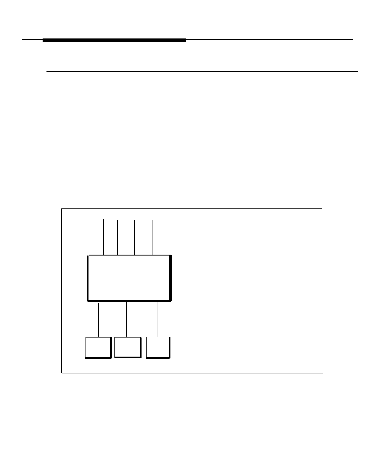
Multiple Answering Machines
If a single answering machine cannot handle all your calls, you can setup two
or more machines to answer (figure 7-7). A setup such as this might be used by
a movie theater to announce movie times to people calling for information.
To retrieve messages:
■
Go to the machines to manually play back messages.
■
From inside the system, make an intercom call to an answering machine
extension. When the machine answers, dial its message retrieval code.
■
From outside the system, call in on any line assigned to the machine. When
the machine answers, dial its message retrieval code. Note, however, that
when calling in from outside, you can only retrieve messages from the first
machine that answers.
ext
ANS
MACH
1
ABC
CONTROL
UNIT
ext
X
ANS
MACH
2
Y
lines
ext
Z
ANS
MACH
3
TO Program:
1.
Use Line Assignment (#301) to assign
all the lines to extensions X, Y, and Z
that you want the machines to cover.
2.
For extension X, set Line Ringing
options for line A to “immediate ring,”
lines B and C to “delayed ring.” For
extension Y, set Line Ringing-Options
for line B to “immediate ring,” lines A
and C to “delayed ring.” For extension
Z, set Line Ringing Options for line C
to “immediate ring,” lines A and B to
“delayed ring.”
3.
Adjust all answering machines to
answer on the same number of rings.
4.
Remove extensions X, Y, and Z from
the Calling Group (#502), the Pickup
Group (#501), and the Night Service
Group (#504).
Figure 7-7 Multiple Answering Machines
7-12 Using Optional Equipment
Page 77

Personal Answering Machine
A personal answering machine is used to answer all the calls that ring on the
lines at a certain extension (figure 7-8). It is useful for the following situations:
■
When the extension receives a lot of intercom calls
■
When outside calls come through a receptionist and are transferred to the
extension
■
When an extension has a private line.
To retrieve calls:
■
From inside the system, make an intercom call to the extension. When the
machine answers, dial the retrieval code.
■
From outside the system, call in and have someone transfer you to the exten-
sion. When the machine answers, dial the message retrieval code. Or, call
in when no one will answer before the answering machine does.
lines
CONTROL
UNIT
.
ext
X
267F2
bridging
adapter
To Program:
1. Set Line Ringing Options for all lines
assigned to extension X to “delayed
ring.”
2. If the lines assigned to extension X are
also assigned to other extensions,
adjust the answering machine to
answer on the third or fourth ring so
that it does not answer calls before
someone else can.
ANS
MACH
Figure 7-8 Personal Answering Machine
Using Optional Equipment
7-13
Page 78

Answering Machine Backup for Fax Machine
If you have a fax machine, and do not want to let an incoming fax call go
unanswered because the fax machine is out of paper, you can back up the fax
machine with an answering machine. In this setup (figure 7-9), if for any reason
your fax machine does not answer, the call is switched over to the answering
machine. The answering machine plays a message like: “The fax machine is
busy—please call back in five minutes.”
You can install the answering machine in two different ways: the answering
machine and fax machine can each go on their own extensions, or they can
share the same extension via an AT&T 267F2 bridging adapter.
Answering Machine and Fax on
Separate Extensions
fax line A
CONTROL
UNIT
ext
X
FAX
To Program:
1. Program Fax Machine Extensions
(#601) as described under “Single Fax
Machine.”
2. Use Line Assignment (#301) to assign
only fax line A to extension Y.
3. Set Line Ringing Options for line A at
extension Y to “delayed ring.”
4. Record appropriate message on
answering machine.
5. Remove extensions X and Y from the
Calling Group (#502), the Pickup Group
(#501), and the Night Service Group
(#504).
ext
ANS
MACH
Y
Answering Machine and Fax on
Same Extension
fax line A
CONTROL
UNIT
ext
X
267F2
bridging
adapter
FAX
To Program:
1. Program Fax Machine Extensions
(#601) as described under “Single Fax
Machine.”
2. Adjust fax machine to answer on first
ring,
3. Adjust answering machine to answer on
third or fourth ring.
4. Record appropriate message on
answering machine.
5. Remove extension X from the Calling
Group (#502), the Pickup Group (#501),
and the Night Service Group (#504).
ANS
MACH
Figure 7-9 Answering Machine Backup for Fax Machine
7-14 Using Optional Equipment
Page 79

Modems
Stand-Alone Modem
There are two ways to use modems with your system:
■
Stand-alone modem.
connect with computer bulletin boards and other data services.
■
Modem pool.
several users to simultaneously use an on-premises computer.
Modems can connect directly to an extension jack without an adapter.To connect modems to the system, see chapter 2 in the Installation and Programming
Guide.
A modem and a terminal allow you to dial out and connect to computer bulletin
boards and other data services. The setup is shown in figure 7-10. Note that
the 267F2 bridging adapter and telephone are optional, and can be used if you
want the terminal to share an extension with a phone.
Uses your PARTNER Plus system like a data switch. Allows
This allows you to dial out into the phone network to
To use:
Follow the modem manufacturer’s instructions.
lines
267F2
bridging
CONTROL
UNIT
adapter
(optional)
ext
modem
PC
terminal
X
telephone
(optional)
To Program:
1. Use Line Assignment (#301) to assign one or more lines to extension X.
2. Set Automatic Privacy (#304) for extension X to “on.”
3. Set Automatic Line Selection for extension X to “outside lines first.”
or
4. Set Line Ringing Options for all lines assigned to extension X to “no ring.”
5. Remove extension X from the Calling Group (#502), the Pickup Group (#501), and the
Night Service Group (#504).
Figure 7-10 Standalone Modem
Using Optional Equipment
7-15
Page 80

Modem Pool
ext W
modem
You can set up your PARTNER PI
several people to simultaneously use a single on-premises computer (figure
7-11).
To install:
To use:
call to the Calling Group. It will be connected to the first available modem.
Plug each modem connected to the computer into its own extension
Any extension with a modem can dial into the computer by making a
267F2
bridging
adapter modem
CONTROL
UNIT
ext
US
system as a small data switch that allows
PC
or
terminal
V
telephone
(optional)
X
Y
Z
COMPUTER
To Program:
1.
Set Automatic Privacy (#304) for extensions V, W, X, Y, and Z to “on.”
2.
Use Line Assignment (#301) to remove all lines from extensions W, X, Y, and Z.
Use Calling Group (#502) to put all the modems connected to the computer
3.
(extensions W, X, Y, Z) into the Calling Group. These must be the only extensions in
the Calling Group.
4.
Adjust each modem in the Calling Group to answer on a progressively higher ring.
For example, set modem 1 to answer on the first ring; set modem 2 to answer on
the second ring; etc.
5.
Remove extension V from the Calling Group (#502), the Pickup Group (#501), and
the the Night Service Group (#504).
6.
Remove extensions W, X, Y, and Z from the Pickup Group (#501) and the Night
Service Group (#504).
Figure 7-11 Modem Pool
7-16 Using Optional Equipment
Page 81

Credit Card Scanners
Many retail businesses and restaurants use credit card scanners to get instant
approval of credit card purchases. The PARTNER Plus system allows your
credit card scanners to share the lines in your system.
CONTROL
ext
X
Credit
Card
Scanner
UNIT
TO use:
automatically selected.
When you make a call on the credit card scanner, an outside line is
lines
To Program:
1. Use Line Assignment (#301) to assign the
lines you want the terminal to use to
extension X.
2. Set Automatic Privacy (#304) for extension X to “on.”
3. Set Automatic Line Selection for extension
X to “outside lines first.”
4.
Remove extension X from the Calling
Group (#502), the Pickup Group (#501),
and the Night Service Group (#504).
For multiple scanners, follow the above procedure
for each extension.
Figure 7-12 Credit Card Scanner
Using Optional Equipment 7-17
Page 82

Troubleshooting
8
8-i
Page 83

When You Have a Problem
If you should have a problem with your system, there is a good chance you can
solve it by following the appropriate procedure in this section.
If you need help, call:
The Helpline is open 24 hours a
day.
National Service Assistance Center Helpline
1 800 628-2888
If you call, the Helpline representatives can better help you if you have the
following information ready:
■
The kind of system you have (PARTNER Plus)
■
The number of lines and extensions in your system
■
The model number of the problem phone, if applicable (located on the upper
right-hand corner of the phone—MLS-12D, MLS-12, or MLS-6).
If you followed a troubleshooting procedure and need more help, tell the
representative what you did.
Troubleshooting 8-1
Page 84

All Phones Dead: No Dial Tone or Lights
Possible Cause
1. Control unit not
receiving power.
2. The power outlet
may be faulty.
Do This
Locate the control unit.
Make sure the power cord
is plugged securely into
the wall outlet. Also make
sure all circuit breakers
(little plastic pop-up tabs)
are in the “ON” position,
i.e., pushed down. (For
location of circuit breakers, see figure 1-1 in
chapter 1.) To view all circuit breakers, remove the
cover from the control unit.
Test
the
outlet by plugging
in an appliance, like a
lamp or radio.
If...
The green indicator lights The problem is corrected.
on the modules are “ON”
and the trouble is gone,
The green indicator lights
on the modules are “ON”
but the trouble remains,
The green indicator lights
on the modules are “OFF,”
Any green indicator lights
on the modules are “OFF”
or “FLASHING,”
The appliance does not
work,
The appliance works, Call 1 800 628-2888.
Then:
Call 1 800 628-2888.
Go to Possible Cause 2.
Call 1 800 628-2888.
The outlet is faulty. If possible, plug the control unit
into a different outlet.
Check fuse box or call an
electrician.
8-2 Troubleshooting
Page 85

Phone Has Lights but No Dial Tone
Possible Cause
1. Faulty telephone.
2. Bad telephone
cord.
3. Bad adapter or
combination device.
Do This
Unplug the cord from the
base of the problem
phone and plug it into a
phone that works.
Unplug the cord from the
base of the phone and the
wall jack. Replace it with
a cord that works.
If the phone is part of a
combination extension
with another phone or
device, unplug the
adapter from the wall jack.
Unplug the phone’s cord
from the adapter and plug
it directly into the wall
jack.
If...
The other phone works,
The other phone does not
work,
If the phone works,
If the phone does not
work, and it is part of a
combination extension,
If the phone does not
work, and it is not part of a
combination extension,
The phone works,
The phone does not work,
Then:
The old phone was faulty.
Call 1800628-2888 to
arrange for a replacement.
Go to Possible Cause 2.
The cord is bad. Call
1 800 628-2888 to arrange
for a replacement.
Go to Possible Cause 3.
Call 1 800 628-2888.
There is a problem with
the other device attached
to the extension or the
bridging adapter.
Replace the other device.
If the problem is still not
fixed, call 1 800 628-2888.
Call 1 800 628-2888.
Troubleshooting
8-3
Page 86

Trouble Making Outside
Calls
Trouble making outside calls could be one of the following:
■
You hear a dial tone, but the dial tone continues as you try to dial.
■
You hear a dial tone, the dial tone cuts off when you dial, but the line does not ring.
■
You hear a busy signal as you dial.
■
You hear nothing at all.
Possible Cause
1. Local phone com-
pany changed service from rotary to
touch-tone.
2. Someone may
have changed your
Call Restriction settings.
3. Local phone company is not accurately receiving the
dialing signals.
4. Local phone company wiring is faulty.
Do This
If your system was setup
for rotary service, find out
if your local telephone
company has changed to
touch-tone. If it has
changed, you must
change the Dial Mode
(#201) from “rotary” to
“touch-tone.” See chapter
3 in the Installation and
Programming Guide.
Find out: were you able to
make a call without any
trouble before?
lsolate the problem. Make
calls on the telephone
using different lines. Then,
make calls on different
phones using the same
line.
One at a time, unplug
each outside line from the
206 module inside the
control unit. Plug it into a
standard telephone and
try to make a call.
If...
You can make a call,
The dial mode is already
set correctly,
If you were able to call on
the phone before,
If you cannot make calls
from one phone on all
lines,
If you cannot make calls
using different phones,
The trouble appears on
the standard phone,
The trouble does not
appear on the standard
phone,
Then:
The problem is solved.
Go to Possible Cause 2.
Someone may have intentionally changed the
system’s or extension’s
setting. Check to see if
this is true. If you find out
that no one has changed
any system settings, and
the phone used to work,
go to Possible Cause 3.
Follow procedure for
“Phone Has Lights but No
Dial Tone,” Possible
Cause 1.
Go to Possible Cause 4.
There may be a problem
with your outside line.
Report the trouble to your
local phone company.
The trouble is with the
control unit. Call
1 800 628-2888.
8-4 Troubleshooting
Page 87

Phone Does Not Ring
Possible Cause
1. Volume control set
too low.
2. Do Not Disturb If Do Not Disturb is turned
feature turned on.
3. Phone’s Line Ringing may be programmed for “no
ring” or “delayed
ring.”
Do This
Press the volume control
button to increase ringer
volume.
Check to see if Do Not
Disturb is turned on.
Check to see of phone’s
Line Ringing is programmed for “no ring” or
“delayed ring.” Refer to
chapter 4 in the lnstalla-
tion and Programming
Guide.
If...
Phone rings increasingly
louder,
Phone still does not ring,
on,
If Do Not Disturb is not
turned on,
Line Ringing is set for “no
ring” or “delayed ring,”
Line Ringing is set for Phone may be faulty. Fol“immediate ring,” low troubleshooting pro-
Then:
Problem is solved.
Go to Possible Cause 2.
Turn it off by pressing the
programmed button.
Go to Possible Cause 3.
Change programming if
necessary.
cedure for “Phone Has
Lights but No Dial Tone.”
Troubleshooting 8-5
Page 88

Calls are Answered Automatically
Problem: A call rings once, then disappears as if it were answered.
Possible Cause
1. An optional dev-
ice, such as a fax
machine, answering
machine, or modem,
answers when it
should not.
2. PARTNER Plus
system is programmed incorrectly.
Do This
Be sure the device is set
to answer correctly. If the
device answers before it is
supposed to, adjust it to
answer on a later ring. If
the device is not supposed to answer calls at
all, turn its auto-answer
feature off. Refer to the
device’s user manual.
For every optional device
connected to your system,
be sure its extension’s
Line Ringing is set to
“delayed ring.” if it is set
to “immediate ring,” adjust
the device to answer on a
later ring.
If...
The optional device was
set properly,
The optional device was
set improperly,
If the problem is not
solved,
Trouble Hearing Called Party Answer
Then:
Go to Possible Cause 2.
Reset device. if problem
remains, go to Possible
Cause 2.
Call 1 800 628-2888.
Possible Cause
If the system is set
for rotary dialing, the
Rotary Dialing
Timeout interval is
too long. (If the systern is set for touchtone dialing, you
could have a faulty
phone and/or cord.
See “Phone Has
Lights but No Dial
Tone.”)
8-6 Troubleshooting
Do This
Reset the Rotary Dialing
Timeout interval. Refer to
chapter 3 in the Installa-
tion and Programming
Guide.
If...
You can hear the called
party answer,
The problem is not solved,
Then:
The problem is solved.
Reset the Rotary Dialing
Timeout interval to 12
seconds. If problem is still
not solved, call 1 800
628-2888.
Page 89

Using the Recall Feature Has No Effect
Possible Cause
Recall Timer Duration
set too short.
Do This
Increase the Recall Timer
Duration by 100 milliseconds. See chapter 3
in the Installation and Pro-
gramming Guide.
If...
The Recall feature works,
The Recall feature still Continue increasing the
doesn’t work,
Then:
The problem is solved.
Recall Timer Duration by
increments of 100 milliseconds until the problem is solved.
Using the Recall Feature Disconnects Call
This problem applies when the PARTNER Plus is installed behind a PBX or Centrex.
Possible Cause
Recall Timer Duration Decrease the Recall Timer
set too long.
Do This If...
Duration by 100 mil- properly,
liseconds. See chapter 3
in the Installation and Pro-
gramming Guide.
The Recall feature works
The Recall feature still Continue decreasing the
disconnects calls,
Then:
The problem is solved.
Recall Timer Duration by
increments of 100 milliseconds until the probIem is solved.
I
Troubleshooting
8-7
Page 90

Calls on Hold Are Disconnected
Possible Cause
Hold Disconnect
Time is programmed
incorrectly—too
short.
Call on
Possible Cause
Hold Disconnect
Time is programmed
incorrectly—too long.
Hold Hangs Up,
Do This
Change the Hold Disconnect Time from “short” to
“long.” See chapter 3 in
the Installation and Pro-
gramming Guide.
If...
Calls on hold are no
longer disconnected,
Calls on hold still get
disconnected,
The Hold Disconnect Time
was already set to “long,”
but Line Does Not Disconnect
Do This If...
Change the Hold Disconnect Time from “long” to
“short.” See chapter 3 in
the Installation and Pro-
gramming Guide.
Abandoned calls on hold The problem is solved.
are disconnected,
Calls on hold still get
disconnected,
The Hold Disconnect Time
was already “short,”
Then:
The
problem is solved.
Call 1 800 628-2888.
Call 1800
Then:
Call 1 800 628-2888.
Call 1 800 628-2888.
628-2888.
8-8 Troubleshooting
Page 91

Phone Rings Back After Intercom Call with NO One at Other End
Possible Cause
Automatic Line
Selection is programmed incorrectly.
Do This
If one of the phones
involved is a standard
single-line rotary or touchtone telephone, program
its Automatic Line Selection to "Intercom first."
If...
The problem is not solved,
Then:
Call 1 800 628-2888.
Combination Extension Problem: Phone Does Not Ring Properly
Possible Cause
1. Ringer equivalents
are too high for the
extension.
2. Optional device
(fax, answering
machine, etc.) is
faulty.
Do This
If this is a combination The ringer functions prop- Problem is with optional
extension (two devices), erly,
be sure the total of their
Ringer Equivalence
Numbers (REN) does not
exceed 2. (See chapter 2
in the Installation and Pro-
gramming Guide.) If it
exceeds 2, unplug the
extra device.
Remove the optional dev- The ringer functions prop- Problem is in the optional
ice from the extension.
If...
Trouble still appears,
erly,
Trouble still appears, Problem is with control
Then:
device. The system is
okay.
Go to Possible Cause 2.
device. The system is
okay.
unit. Call 1 800 628-2888.
Troubleshooting
8-9
Page 92
Phone Display Does Not Work
Possible Cause
1. Phone has to be To reset the phone,
reset.
2. Phone is faulty.
Do This
unplug the cord from
bottom of the phone and
plug it in again. IMPOR-
TANT: Make sure the
handset is hung up when
you plug the cord in.
Replace problem phone New phone works,
with another PARTNER
display phone.
PARTNER Phone Does Not
If...
The display works,
the
The display still does not
work,
New phone does not work,
Work When Standard Phone Handset Is
Then:
Problem is solved.
Follow procedure for
“Phone Has
Dial Tone.”
Old phone was bad.
Call 1 800 628-2888 to
arrange for a replacement.
Call 1 800 628-2888.
Lights but No
Lifted
This problem relates to combination extensions that have a PARTNER phone and a standard phone.
Possible Cause
Wrong cord and First, unplug the bridging
wrong bridging
adapter used to connect standard phone.
Do This
adapter from the wall jack.
Then, unplug the
PARTNER phone from the
adapter and plug it into
the wall jack.
If...
The PARTNER phone
works properly,
Then:
Either the cord or the
adapter must be replaced.
(Use only an AT&T 267F2
bridging adapter.) Call 1
800 628-2888 for details.
Combination Extension Problem: PARTNER Phone Shows Line Is Busy
Possible Cause
Standard phone is
not hung up.
8-10 Troubleshooting
Do This If...
Hang up standard phone.
PARTNER phone light
goes off,
Standard phone is hung
up,
Then:
Problem is solved.
Reset PARTNER phone
according to procedure
given under “Other Problems with Phones.”
Page 93
Other Problems with Phones
This procedure resets a PARTNER telephone. Use it if you have any problems that are not mentioned above.
Possible Cause
Phone
reset.
needs to be
Do This
Unplug the cord from the
bottom of the phone and
plug it in again. IMPOR-
TANT: Make sure the
handset is hung up when
you plug the cord in.
If...
problem remains,
The
Then:
Call 1 800 628-2888
Other Problems With System
This procedure resets the system. Use it only when you have any problems that are not mentioned above.
Possible Cause
1. System needs a
software reset.
Do This
At extension 10:
1. Press
2. Press
(the left
3. Press [#] [7] [2] [8]
[Feature] [0] [0]
[Intercom] [Intercom]
[Intercom]
button)
If...
The problem is not solved,
Then:
Proceed to Possible
Cause 2.
NOTE: A system reset will
disconnect all calls in progress. However, it will not
erase any system programming.
2. System needs a Unplug the control unit’s
hardware reset.
power cord. Wait 10
seconds, then plug it back
in.
The problem is not solved,
Call 1 800 628-2888.
Troubleshooting
8-11
Page 94

In Case Of Power Failure
When power to the system is cut off, the first line on each 206 module automatically connects to the first extension on the module. For example, Line 1 con-
nects to extension 10, Line 3 connects to extension 16, Line 5 connects to
extension 22, and Line 7 connects to extension 28. This allows the system to
maintain telephone service during a power outage.
PARTNER telephones do not work during a power failure— you must use a stan-
dard touch-tone or rotary telephone. For this reason, it is strongly suggested
that you have at least one standard telephone connected—either directly or by
267F2 bridging adapter—to the first extension of every 206 module (extensions
10, 16, 22, or 28). For more information on preparing for operation during a
power failure, see “General Guidelines” in chapter 2 of the Installation and Pro-
gramming Guide.
The PARTNER Plus system has an internal power supply that allows it to stay
programmed for approximately four days after it stops receiving power. After
four days elapse, all of the system’s programmed settings return to the factory
settings.
8-12
Troubleshooting
Page 95

Maintenance and Customer Support
9
9-i
Page 96

Maintenance
Control Unit
PARTNER Telephones
Your PARTNER Plus system is designed to provide trouble-free performance
without any special maintenance procedures. However, there are a few
precautions you can take to prevent accidental damage to your system.
To prevent damage to the system modules:
■
Keep the system modules in an area free of dust, smoke, and moisture.
■
Do not block the air vents by placing objects on top of the control unit.
■
Place control unit in a place with a temperature between 32 degrees and 104
degrees Fahrenheit.
■
Do not place the control unit in direct sunlight.
To prevent damage to PARTNER telephones:
■
Do not place your telephones near a heating duct, radiator, or other heat
source.
■
Do not drop your telephones or expose them to excessive shock or vibration.
■
Unplug the telephone
■ Its cord is damaged
■ Liquid is spilled into it
■
Its housing becomes cracked or otherwise damaged
■
To clean your telephone, wipe the outside housing with a soft, dust-free
if:
cloth. If absolutely necessary, you may clean it with a soft cloth slightly
dampened with a mild soap and water solution. Dry quickly with a soft cloth.
CAUTION:
Your telephone contains sensitive electronic parts. Never
submerge it in any kind of liquid, and never use detergents, alcohols,
solvents, abrasive cleaners, or an excessive amount of water when
cleaning the housing and faceplate. To do so could result in irreparable
damage.
Maintenance and Customer Support
9-1
Page 97

Customer Support
AT&T customer support personnel can help you program or use the system and
telephones. In the U.S., call the following toll-free number 24 hours a day:
AT&T
General Business Systems
National Service Assistance Center Helpline
1 800 628-2888
In Canada, call the nearest Technical Assistance Center:
Eastern Canada and Ottawa:
Ontario:
Central and Western Canada:
Before calling the Helpline, refer to “Troubleshooting,” chapter 8.
Warranty and Post-Warranty Repair
In-Warranty Repairs
Post-Warranty Repairs
If you purchased or leased your PARTNER Plus system directly from AT&T,
AT&T will repair it free of charge during the one-year warranty period. Simply
call the Helpline at 1 800 628-2888 to ask for service.
Business-Day service is standard during the warranty period for both the control
unit and PARTNER phones. Business-Day service is performed during normal
business hours. However, if you need 24-hour service protection during the
warranty period on the control unit in case there is a major system failure, you
can purchase an Around-the-Clock service contract from your local AT&T sales
office (1 800 247-7000). (Around-the-Clock service is not available for phones.)
If you purchased or leased your system through an AT&T-authorized dealer,
contact your dealer for repairs.
If you purchased your system from AT&T and you have a post-warranty service
contract, AT&T service is provided under the terms of that contract.
1 800 363-1882
1 800 387-4268
1 800 663-9817
9-2
Maintenance and Customer Support
If you do not have a contract, AT&T service is provided on a time-and-materials
basis by calling the Helpline at 1 800 628-2888. T
costs after the warranty period, you can purchase a post-warranty service contract from AT&T. A contract entitles you to unlimited service calls with no
charge for parts and labor, plus preferred dispatch priority. Both Business-Day
and Around-the-Clock coverages of varying lengths are available. To order a
post-warranty service contract, please call 1 800 247-7000.
If you leased your system from AT&T, Business-Day service is included in your
lease. To upgrade to Around-the-Clock service, call 1 800 247-7000.
If you purchased or leased your system through an AT&T-authorized dealer,
contact your dealer for repairs.
O
eliminate unexpected repair
Page 98

AT&T Limited Warranty and Limitation of Liability
AT&T warrants to you that your PARTNER Plus Communications System will be
in good working order when you take title and that it will remain in good working
order for a period of one year (the warranty period) or AT&T will, at its option,
repair or replace the system component that is not in good working order. Any
repair or replacement components may be new or refurbished and will be pro
vided on an exchange basis. If AT&T determines that your PARTNER Plus system cannot be repaired or replaced, AT&T will refund the purchase price of the
PARTNER Plus system to you. If you purchased your PARTNER Plus system
directly from AT&T, AT&T will perform warranty repair on your premises in
accordance with the terms and conditions of AT&T’s “Business Day” or “Around
the Clock’’ warranty plans. The details of AT&T’s warranty plans may be
obtained from AT&T by calling 1 800 247-7000. If you purchased your
PARTNER Plus system from an AT&T authorized dealer, you will be covered by
AT&T’s Authorized Dealer Warranty Plan during the warranty period. Contact
your Authorized Dealer for details of AT&T’s Authorized Dealer Warranty Plan.
AT&T’s obligation to repair, replace, or refund as set forth above is your
exclusive remedy.
The limited warranties provided above do not cover damages, defects,
malfunctions, or product failures caused by:
■
Failure to follow AT&T’s installation, operation, or maintenance instructions.
■
Unauthorized modification or alteration of the PARTNER Plus system or its
components.
■
Product abuse, misuse, or the negligent acts of persons not under the
reasonable control of AT&T.
■
Actions of third parties and acts of God other than power surges (e.g.,
lightning).
This warranty applies to a PARTNER Plus system purchased directly from AT&T
or purchased directly from an authorized AT&T Dealer.
Except as specifically set forth above, AT&T, its affiliates, suppliers, and dealers
make no warranties, express or implied, and specifically disclaim any warranties
of merchantability or fitness for a particular purpose.
Except for personal injury, the liability of AT&T, its affiliates, suppliers and
dealers for any claim, loss, damage, or expense from any cause whatsoever
regardless of the form of the action, whether in contract, tort, or otherwise, shall
not exceed the lesser of direct damages proven or the repair or replacement
cost of the PARTNER Plus system or the PARTNER Pius system's purchase
price. In no event shall AT&T, its affiliates, suppliers, or dealers be liable for
incidental, reliance, consequential or any other indirect loss or damage (including lost profits or revenues) sustained or incurred in connection with the
PARTNER Plus system. This limitation of liability shall survive failure of the
exclusive remedy set forth in the limited warranty above.
Maintenance and Customer Support
9-3
Page 99

Except for damages for personal injury, the liability of AT&T, its affiliates, suppliers and dealers for any loss or damage resulting from any product defector
performance under this warranty and regardless of the form of action shall be
limited to repair or replacement of the product or a refund of the product’s purchase price. In no event shall AT&T, its affiliates, suppliers, and dealers be
liable for indirect, reliance, incidental or consequential damage or loss (including
loss of profits) caused or alleged to have been caused by this product.
This warranty applies only to a product purchased directly from AT&T or
purchased directly from a dealer authorized by AT&T to sell the product.
9-4
Maintenance and Customer Support
Page 100

User Forms
A
This appendix contains two forms to be photocopied and handed out to system
users. These forms are:
■
System Speed Dial Form.
Dial numbers and system extension numbers. For instructions on
programming System Speed Dial numbers, see chapter 4 in this guide.
■
Extension Programming Information Form.
about what their phones can and cannot do, according to how each
extension is programmed. Instructions for completing the form are on the
reverse side of the form.
Provides space on which to write System Speed
Provides information for users
We suggest you fill in a photocopy of the forms, leaving blank originals in the
book, in case you need to distribute revisions in the future.
User Forms A-1
 Loading...