

Page 1

AT&T
PARTNER™
Communications System
Installation and Use
Page 2

Copyright © 1990 AT&T
All Rights Reserved
Printed in U.S.A.
AT&T 999-506-139
Issue 2
October 1990
Notice
Every effort was made to ensure that the information in this document was complete and accurate at the time of
printing. However, information is subject to change.
Federal Communications Commission (FCC) Information
For important FCC interference, registration, and repair information, see appendix D of this document.
Trademarks
PARTNER is a trademark of AT&T.
MLS-6 and MLS-12 are trademarks of AT&T.
MERLIN is a registered trademark of AT&T.
SYSTIMAX is a trademark of AT&T.
Warranty
AT&T provides a limited warranty to this product. Refer to “AT&T Limited Warranties” in chapter 8.
Ordering Information
The order number for this book is 999-506-139. To order copies of this document, call 1 800 432-6600 in the U.S.
or 1 800 255-1242 in Canada. For more information on how to order this and other PARTNER™ system reference
materials, refer to "Reference Materials" in the section entitled "About This Guide." For information on ordering
replacement parts, accessories, and other compatible equipment, refer to appendix C.
Support Telephone Numbers
AT&T provides a toll-free customer helpline 24 hours a day. In the U.S., call the AT&T Helpline at 1 800 628-2888 if
you need assistance when installing, programming, or using your system. In Canada, call one of the following
Technical Assistance Centers for service or technical assistance:
Eastern Canada and Ottawa:
Ontario:
Central and Western Canada:
1 800 363-1882
1 800 387-4268
1 800 663-9817
Page 3

Contents
About This Guide
1
2
3
System Overview
Features and Capabilities
■
■
System Components
Optional Equipment
■
Specifications
■
Quick Start
■
Installing the Hardware
Before You Start
■
Installing System Modules
■
Connecting Equipment
■
Replacing Modules
■
Customizing Your System
iii
1-i
1-1
1-2
1-3
1-5
1-6
2-i
2-1
2-4
2-9
2-14
3-i
Overview
■
Changing Factory Settings
■
Speed Dialing
■
Auto Dialing
■
Special Dialing Functions
■
4
Basic Call Handling with PARTNER Phones
PARTNER Phone Controls
■
Using the Auto Dial Buttons
■
Call Handling
■
Built-In Calling Features
■
3-1
3-2
3-5
3-6
3-7
4-i
4-1
4-4
4-5
4-11
i
Page 4

5
Using Standard Telephones
■
Overview
■
Call Handling
5-i
5-1
5-2
6
7
8
A
B
Using Optional Equipment
■
Fax Machines
■
Answering Machines
■
Modems
■
Credit Card Scanners
Troubleshooting
Maintenance and Customer Support
Use Behind PBX or Centrex
User Form
6-i
6-1
6-7
6-11
6-12
7-i
8-i
A-1
B-1
C
D
E
IN
ii
Ordering Information
FCC Information
Upgrading Your System
Index
C-1
D-1
E-1
IN-1
Page 5

About This Guide
How to Use This Guide
Reference Materials
This guide provides instructions on how to set up and use the PARTNER™
Communications System.
If you are installing and using your PARTNER system for the first time, we
recommend that you read chapters 1 through 5 to Iearn what the PARTNER
system can do. However, if you want to set up your system and use it quickly,
read the System Overview (chapter 1) and use the Quick Start table on page
1-6. Then read through this manual.
Once you are experienced with the PARTNER system, use the Table of Contents
or Index to locate the information you need.
Quick Reference for Use with MLS-6™ and MLS-12™ Telephones (999-506-144,
in packages of 6) are available to help you use the PARTNER system.
To order additional or replacement reference materials, call the AT&T Customer
Information Center (CIC):
In the U.S.: 800 432-6600
In Canada: 800 255-1242
Product Safety Labels
This book contains several product safety Iabels, identified by a . A
CAUTION
property damage or minor personal injury if the hazard is not avoided.
Carefully read the
module will expose you to hazardous voltages that can cause severe personal
injury or death.
How to Comment on This Guide
A feedback form is located at the end of this guide, after the appendixes. If the
feedback form is missing, send your comments and recommendations for
changes to:
A. Sherwood
AT&T General Business Systems
Room 2B-63
99 Jefferson Road
Parsippany, NJ 07054
Fax: 201 887-6898
label indicates the presence of a hazard that will or can cause
WARNING
label on pp. 2-8, 7-1, and 8-1. Opening a 206
About This Guide iii
Page 6

System Overview
Contents
1
Features and Capabilities
System Components
Optional Equipment
■
Industry Standard Devices
Limitations
Connecting and Using Standard Devices
■
Other Devices
■
Ordering Information
Specifications
Quick Start
1-1
1-2
1-3
1-3
1-3
1-4
1-4
1-4
1-5
1-6
1-i
Page 7

Features and Capabilities
Your PARTNER™ system is easy to install, set up, and use. The best way to get
started with the PARTNER system is to read this manual straight through. If
you’re in a hurry to set up and use the system, you can read this chapter and
use the Quick Start table on page 1-6. But you will eventually need to read this
manual to learn about all the capabilities of the system and how it can work for
you.
The PARTNER system can handle as many as 4 outside telephone lines and 12
extensions. The PARTNER system has many features that help you manage
your phone calling and save money. For example:
■
Direct connection
answering machines, and fax machines means you do not have to buy extra
lines or expensive adapters to connect phone equipment you may already
own.
of standard single-line touch-tone and rotary telephones,
Easy, one-touch use of features
■
such as Last Number Redial and Privacy
with AT&T MLS-12™ phones.
Auto Dialing
■
makes it possible to dial long or frequently used numbers with
a single touch.
■
System Speed Dialing
allows people to dial frequently called numbers by
dialing a short code.
■
Dialing Restriction feature
allows you to keep phone bills down by
restricting the kinds of calls people can make.
Interchangeable system parts
■
make it easy to add or remove modules to
expand or repair your system.
System Overview 1-1
Page 8
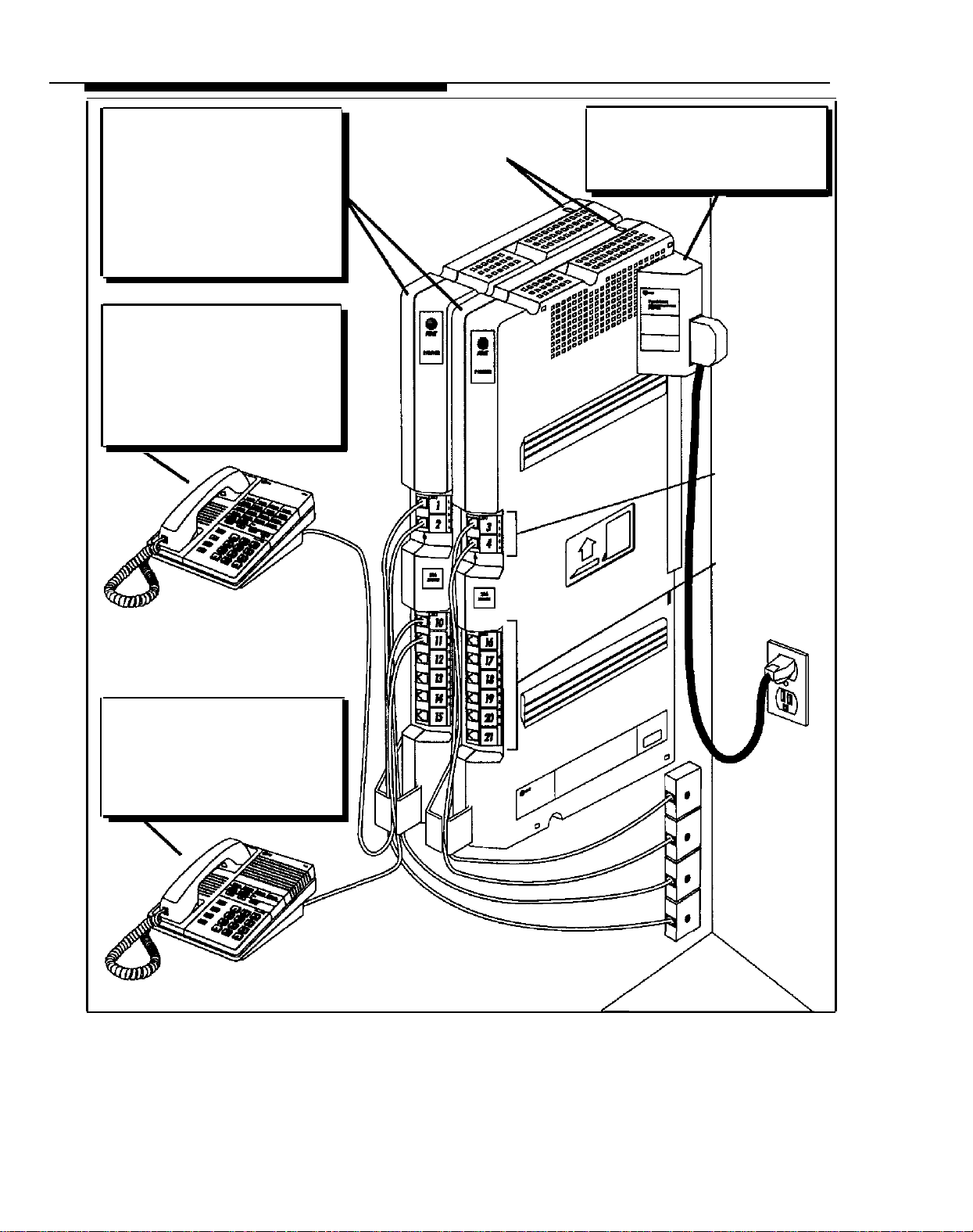
System Components
206 MODULE
A system can have one or two 206
modules. Each 206 module connects
up to 2 telephone company lines
and up to 6 telephones or other
devices such as fax machines,
answering machines, and modems.
With two 206 modules, you can
connect 4 outside lines and
12 extensions. Each 206 module
has a green light that shows it is
turned on.
MLS-12™ (Multi-Line Series)
TELEPHONE
This phone has four buttons for
outside lines, two intercom buttons,
four Calling Feature buttons, and
eight Auto Dial buttons. It also has
a built-in speaker and microphone.
Throughout this guide, the
AT&T MLS-12 phone is referred to
as the PARTNER 12-button phone.
Circuit Breakers
MODULE CONNECTOR
This connector is needed only if you
have two 206 modules. It joins the
modules together so that all the lines
and telephones on both modules are
connected.
Outside Line Jacks
Extension Jacks
PARTNER 12-Button Telephone
(MLS-12)
MLS-6™ TELEPHONE
This telephone has six buttons with
lights, which include four buttons
for outside lines and two intercom
buttons. It also has a built-in
speaker. Throughout this guide, the
AT&T MLS-6 phone is referred to as
the PARTNER 6-button phone.
PARTNER 6-Button Telephone
(MLS-6)
Figure 1-1 PARTNER System Components
Outside Line Cords
1-2
System Overview
Page 9

Optional Equipment
The PARTNER system works with many telecommunications devices, not only
PARTNER telephones. You can connect these other devices without investing in
more lines or circuit cards.
Industry Standard Devices
Many types of industry-standard telecommunications devices will work with your
PARTNER system. They include:
■
Standard single line touch-tone and rotary telephones.
these phones for almost all of your normal phone calling. In fact, you should
connect at least one standard phone to the system because it is the only
kind that will work on the PARTNER system during a power failure. See
chapter 5 for instructions on using standard phones.
■
Single-line cordless telephones.
phones for almost all of your normal phone calling while having the freedom
to move around your premises.
Fax machines.
■
PARTNER system, so you do not have to pay for an extra dedicated outside
line. For information on how to use a fax machine with the PARTNER system,
see chapter 6.
Answering machines.
■
Iines with a single answering machine. For instructions on how to use
answering machines with the PARTNER system, see chapter 6.
Modems.
■
receive data over telephone lines. For instructions on how to use modems
with the PARTNER system, see chapter 6.
Credit card verification terminals.
■
minal, you can connect it directly to your PARTNER system. For instructions
on how to use a credit card verification terminal with the PARTNER system,
see chapter 6.
You can use
You can use single-line cordless tele-
You can save money by connecting your fax machine to the
With the PARTNER system, you can cover up to four
You can use a modem with your personal computer to send and
If you use a credit card verification ter-
Limitations
You can connect the above devices to your system regardless of the manufac-
turer. However, the following limitations apply:
■
It must be a single-line device.
■
It must be industry standard. That is, it cannot be made specifically for use
on a particular telephone system. (For example, you cannot connect an
AT&T MERLIN® phone because it is specifically designed for use on a
MERLIN system.)
In order for the phones or devices to ring properly, the total Ringer
■
Equivalence on a single extension cannot exceed 2. Every device has a
label showing its Ringer Equivalence Number (REN). If you are connecting a
single device to the extension, its REN cannot be more than 2. If connecting
two devices, their total RENs cannot be more than 2.
System Overview 1-3
Page 10

Connecting and Using Standard Devices
Other Devices
You can connect the standard device so that it is on an extension by itself, or it
can share an extension with another piece of equipment (either another standard device or a PARTNER phone). To connect two devices on one extension,
you will need an AT&T 267F2 bridging adapter. (Two of these bridging adapters
are included with each 206 module.) ln addition, the total RENs for both devices must not exceed 2. See pages 2-12 and 2-13 for installation instructions.
For information on using standard devices with your PARTNER system, see
chapters 5 and 6.
You can also connect other devices to your system, but only specific models are
compatible with the PARTNER system. Contact an AT&T sales representative
for datails. These devices include:
■
Loudspeaker paging systems.
large area.
Headsets.
■
on your head, so you can have a private, hands-free conversation. It is useful for receptionists, salespeople, or others who may need to use have their
hands free while talking on the phone. For information on how to use headsets, see the manufacturer’s instructions.
Extra alerts.
■
to ring when a call comes in. For information on how to use these alerts, see
the manufacturer’s instructions.
A headset is a combination earphone and microphone you wear
You can connect extra alerting devices, such as bells or horns,
Allows you to broadcast a message over a
Ordering Information
1-4 System Overview
Optional equipment is available from many AT&T sources. Contact your AT&T
representative or any of the following for sales information and advice on the
equipment that would best meet your needs.
AT&T Catalog Sales
AT&T General Business Systems Sales Office
AT&T PhoneCenter Store
AT&T-Authorized Dealer
For more information, see appendix C.
1 800 451-2100
1 800 247-7000
1 800 222-3111
1 800 247-1212
Page 11

Specifications
Table 1-1 System Specifications
Capacities
Dimensions
Weights
(approx.)
Switch Fabric
Electrical
Specifications
Extension Jack
Specifications
Environmental
Requirements
Electrical
Requirements
Wiring
Local Phone
Company
Information
System
(with two 206 modules)
●
4 outside lines
●
12 extensions
●
Single 206 Module
●
Two Modules and Connector
●
206 Module
●
Module Connector
●
PARTNER 6-Button (model MLS-6) Phone
●
PARTNER 12-Button (model MLS-12) Phone
●
Full digital, nonblocking
●
1 amp per 206 module
●
100 watts per 206 module
●
4-day memory backup (96 hours)
●
Ringing voltage: +5VDC, -140 VDC peak to peak; Trapezoidal wave shaping
●
46-volt talk battery
●
Ringing frequency: 20 Hz
●
Mount on a wall or sturdy, level surface at least 2 feet (.61 meters) from floor. For proper
ventilation, wall mounting is required for 2-module systems (strongly recommended for 1module systems)
●
Locate within 5 feet (1.5 meters) of an electrical outlet not controlled by a switch and within
5 feet (1.5 meters) of the network interface jacks, when using the supplied 7-foot (2.13-meter)
cords.
●
Operating temperature 32° to + 104°F (0° to +40°C), not in direct sunlight
●
Humidity 15%–90%, noncondensing
●
Locate in an area free of excess moisture, corrosive gases, dust, and chemicals
●
For proper ventilation and easy replacement of modules, provide at least 1 foot (0.3 meters)
clearance at the top, bottom, and back; 2 feet (0.6 meters) at the front.
●
90–130 VAC, 50–60 Hz, 3-prong outlet separate ground, separately fused at 15 amps
●
Outlet must not be controlled by an on/off switch
●
Grounding to comply with Underwriters Laboratories (UL) 1459:
A. An insulated grounding conductor that is not smaller in size and equivalent in insulation material and thickness to the
grounded and ungrounded branch circuit supply conductors, except that it is green with or without one or more yel-
low stripes, is to be installed as part of the circuit that supplies the product or system.
B. Connect the grounding conductor to ground at the service equipment.
C. The attachment-plug receptacles in the vicinity of the product or system are all to be of a grounding type, and the
grounding conductors serving these receptacles are to be connected to earth ground at the service equipment.
●
MLS-model phones: AT&T SYSTIMAX™ or at least 2-pair (4-wire) star (“home run” not “loop”)
●
Other standard telecommunications equipment (single-line phones, fax machines, answering
machines, etc.): 1-pair (2-wire) mounting cords (AT&T D2R mounting cords recommended)
●
Bridging adapter: AT&T 267F2
●
Range: 1,000 feet (305 meters) for MLS phones; 3,000 feet (915 meters) for standard devices
●
FCC registration number: AS5 USA-61630-KF-E
●
REN (outside line jack): 0-9A per line jack
●
REN (PARTNER telephone): 0 (zero)
206 Module
●
2 outside lines
●
6 extensions
Extension Jack
●
Maximum 2 devices per exten-
sion jack, total REN not to
exceed 2* (2 devices require
AT&T 267F2 bridging adapter)
11''(D) x 17''(H) x 1,5''(W) or 4.3cm x 6.6cm x .58cm
11''(D) x 17''(H) x 5''(W) or 4.3cm x 6.6cm x 1.9cm (assembled)
4.5 lbs or 9.9 kgs
1.5 lbs or 3.3 kgs
1.8 lbs or 4.0 kgs
2.0 lbs or 4.4 kgs
●
Dissipation of power (30 watts per 206 module during
normal operation)
●
342 BTUs/hour at peak. 103 BTUs/hour at normal per
206 module
●
Jack type: RJ11C
●
Loop start lines
*The two devices combined on an extension jack can be a PARTNER phone with a standard device, or two standard devices; DO NOT connect
two PARTNER phones to the same extension jack. If a device lists two RENs, use the higher number when adding up RENs.
System Overview 1-5
Page 12
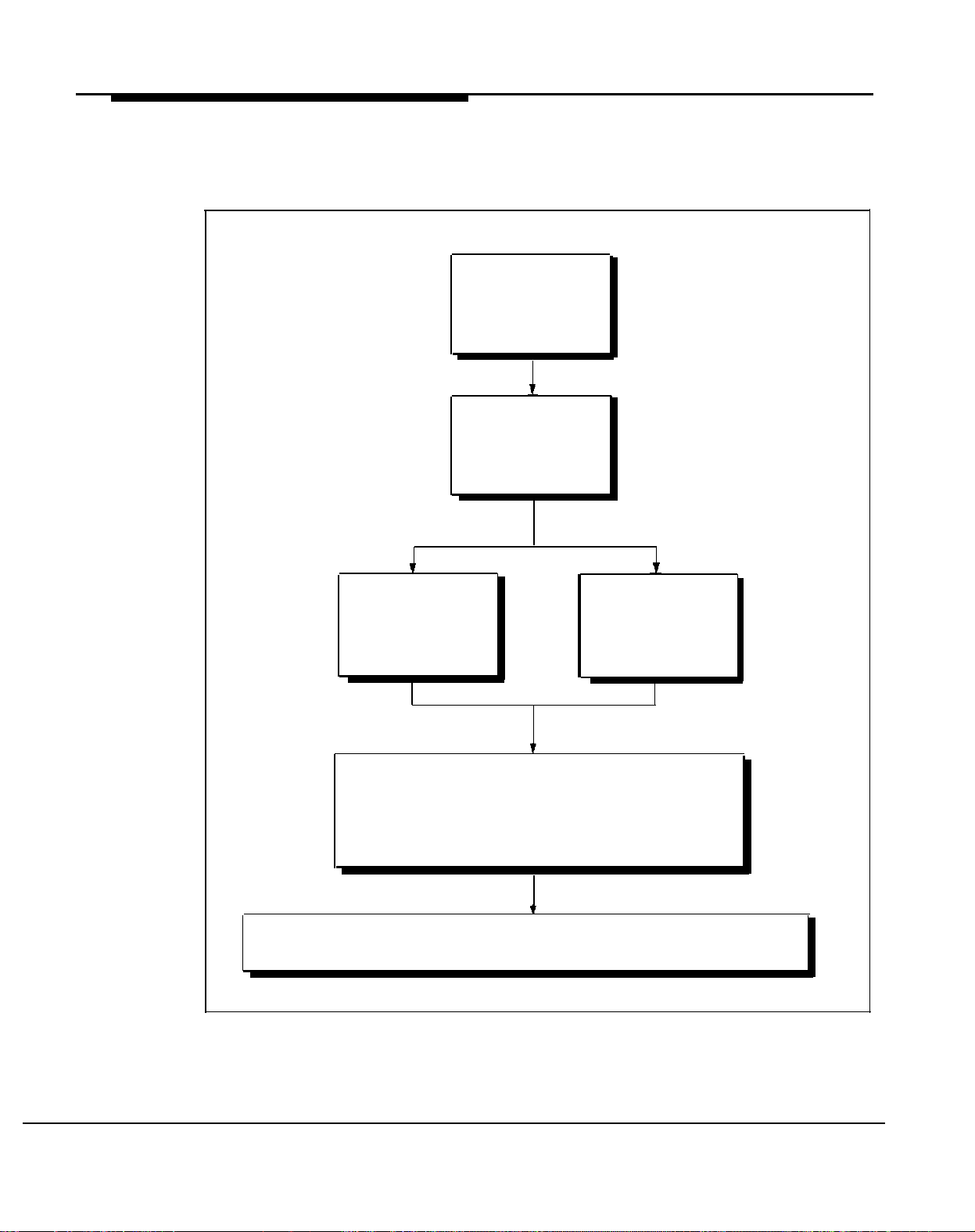
Quick Start
To get started quickly, refer to the figure below for the important steps you must
follow to install and set up the system. Refer to the pages listed to find the additional information you need.
Check the
System Wiring
page 2-1
Install the
System Modules
page 2-4
Install PARTNER
Telephones
page 2-9
Change system settings if the system:
■
has rotary lines, p. 2-12
■
is connected to a PBX or Centrex system,
appendix A
■
Give Quick Reference Cards to users with PARTNER telephones.
■
Give copies of chapter 5 to users with standard telephones.
Figure 1-2 Getting Started Quickly
Install Other
Equipment
page 2-12
1-6 System Overview
Page 13

Installing the Hardware
Contents
Before You Start
■
Check for Outside Lines
Check for Inside Wiring
■
If There Is Wiring
If There Is No Wiring
■
Preparing for a Power Failure
2
2-1
2-1
2-2
2-2
2-3
2-3
Installing System Modules
Connecting Equipment
■
PARTNER Telephones
Connecting Standard Single-Line Equipment
■
Combining Two Devices on One Extension
■
Replacing Modules
2-4
2-9
2-9
2-12
2-13
2-14
2-i
Page 14
Before You Start
Before installing your PARTNER system, you must make sure the system wiring
is ready. This wiring includes both the outside Iines from the local telephone
company and the inside wiring for connecting extensions to the 206 modules
(also called system modules).
You should also plan ahead for using the system during power outages. This
section discusses these two topics.
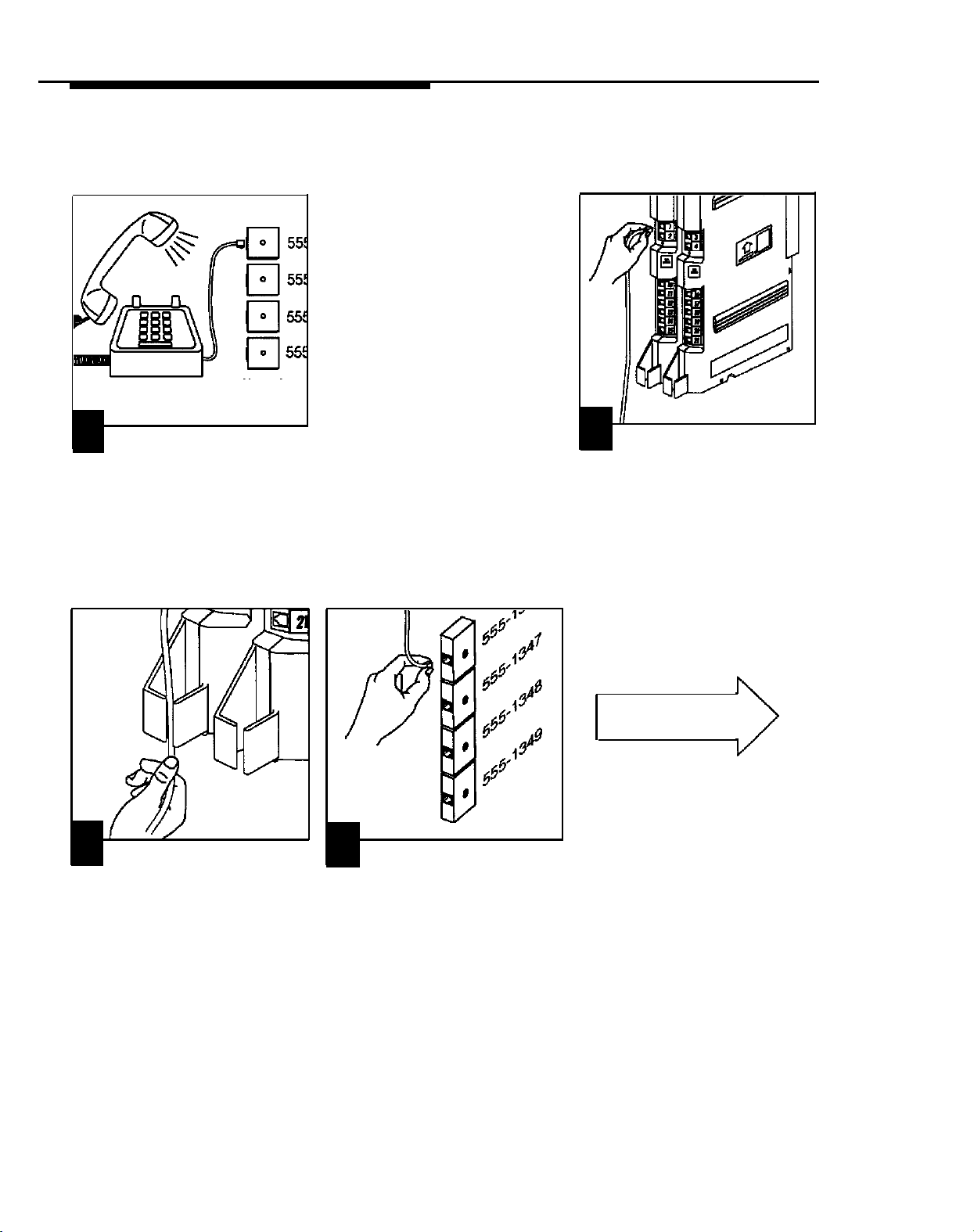
Check for Outside Lines
IMPORTANT:
If you have any problems with the wiring or installation, call
the AT&T Helpline at 1 800 628-2888 or a qualified telephone installer for
assistance.
Make sure the local telephone company has installed the outside lines for the
PARTNER system. Each outside Iine must be connected through an RJ11
network interface jack. These jacks look Iike ordinary wall jacks, but should be
labeled with the telephone number for each outside line (see figure 2-1). If the
network interface jacks are not present, call your local phone company. If two
numbers are assigned to one jack, have the phone company split the lines so
that each line has its own RJ11 jack.
The network interface jacks must be within 5 feet of the system module(s). If
they are not, arrange to have either the local phone company move them or a
qualified telephone installer do the wiring, which requires special expertise and
tools. To arrange for AT&T service, call 1 800 247-7000.
206 (System) Modules
5 feet
(maximum)
Figure 2-1 Network Interface Jacks
555-1346
555-1347
555-1346
555-1349
Network
Interface
Jacks —
Outside Lines
from Phone Company
(one line per jack)
Installing the Hardware
2-1
Page 15

Check for Inside Wiring
Inside wiring (also called “building wiring”) enables you to connect phones and
other equipment to the 206 modules. If the building is already wired, the following section tells you whether or not the wiring will work. If the building is not
wired, you can have it professionally wired or wire it yourself, as described on
the next page.
If There Is Wiring
IMPORTANT:
telephone wiring is "loop" and will
not work.
Ordinary home
Inside wiring consists of wiring runs—one for each extension. A typical wiring
run starts with a wall jack near the system module(s). Then the wiring itself runs
inside the wall to the extension location where it ends in another wall jack. Since
the wiring is hidden, all you see are the wall jacks at both ends (see figure 2-2).
Near the system module(s) there should be a series of jacks, one for each
extension. Each jack is the start of a separate wiring run and should be Iabeled
with either the extension or wiring run number. The wall jacks placed
throughout the building (the ends of the wiring runs) should also be labeled with
the extension or wiring run number.
The PARTNER system works with many types of existing wiring. It requires at
least 2-pair (4-wire) wiring in a “home run” or star (not Ioop) configuration. If
you don’t know whether or not the existing wiring is acceptable, test it as follows
(see figure 2-2):
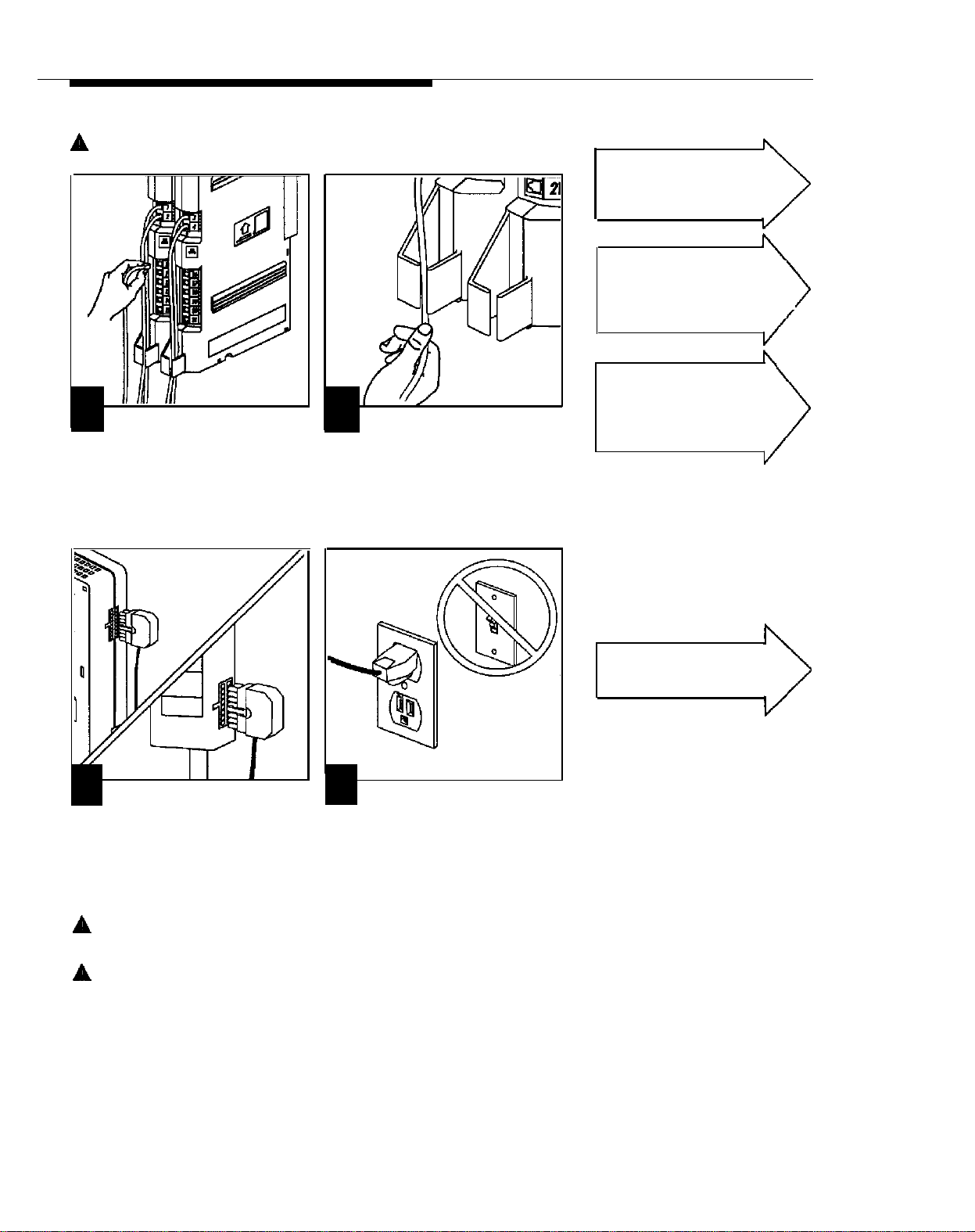
➀
Plug a 206 module into an electrical outlet not controlled by a switch.
Plug one end of a phone cord into an extension jack on the 206 module.
➁
➂
Plug the other end into a wiring run jack.
Plug a PARTNER phone into the wall jack at the end of that wiring run.
➃
Press [
➄
Intercom
] and lift the handset. If you hear a dial tone, the wiring is
acceptable. If you don’t hear a dial tone, read the next section.
2-2 Installing the Hardware
PARTNER Phone
➄
➃
(hidden wiring
Ext. 10
Wall Jack
Figure 2-2 Testing Inside Wiring
in wiring run)
➂
10 11 12 13 14 15
Wiring Run Jacks
(one per extension)
➁
System (206) Module
Power
Cord
➀
Page 16
If There Is No Wiring
If there is no inside wiring, or the existing wiring is not acceptable, you can
install your own wiring. The type of wiring you use depends on how far the
extension is from the system module(s). For extensions that are within
■
14 feet: use the telephone cords included with the system.
75 feet: use the Extension Wiring Kit (see appendix C to order one kit per
■
extension).
1,000 feet: use DlW 4 twisted-pair wire or call AT&T at 1 800 247-7000.
■
IMPORTANT:
under carpets, consult a qualified telephone installer to ensure that the installation meets local building codes.
Rather than install your own wiring, you can have a qualified telephone installer
do the work. To arrange for AT&T installation, call 1 800 247-7000.
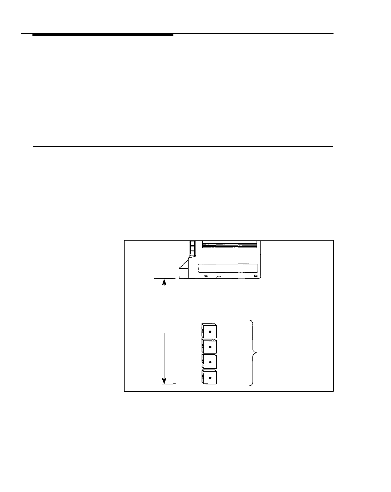
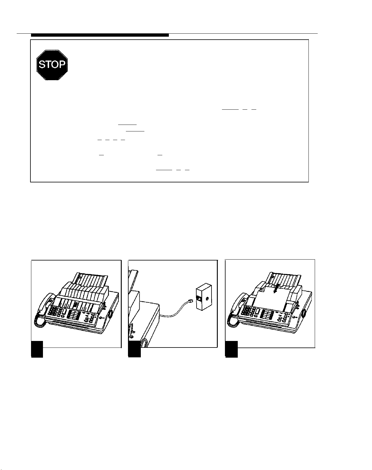
Preparing for a Power Failure
During an electrical outage, your system will lose power. To provide uninterrupted phone service when the system has no power, the first outside line on
each 206 module automatically connects to the first extension on that module.
That is, on the first module, line 1 connects to extension 10; on the second
module, line 3 connects to extension 16 (see figure 2-3). (To easily identify
these jacks, they are both labeled “PFT" for Power Failure Transfer.) However,
bacause PARTNER phones require electricity, you must use a standard touch-
tone or rotary phone to make and receive calls during a power failure. A rotaryIine system requires rotary phones for use during a power failure.
To prepare for a power failure, AT&T recommends:
■
Store standard phones close to extensions 10 and/or 16. During a power
If you combine a standard phone
and PARTNER phone on one
extension, you may want to lower
the ringer volume of the standard
phone during normal use.
failure, replace the PARTNER phone with the standard phone.
■
Or, connect a standard phone to these extensions at all times. On extension
10 combine a PARTNER phone and standard phone. On extension 16 connect the standard phone alone or combine it with a PARTNER phone. Use
only an AT&T 267F2 bridging adapter to combine the two phones (two
adapters are included with each 206 module).
If you need to run the wire inside walls, through ceilings, or
Lines
1 and 3
PARTNER
12-Button
Phone
Standard
Telephone
Wall
Jack
267F2
Bridging
Adapter
Figure 2-3 Power Failure Setup
Ext. 10
Automatic connections
during power outage
Ext. 16
Standard
Telephone
Installing the Hardware
2-3
Page 17
Installing System Modules
■
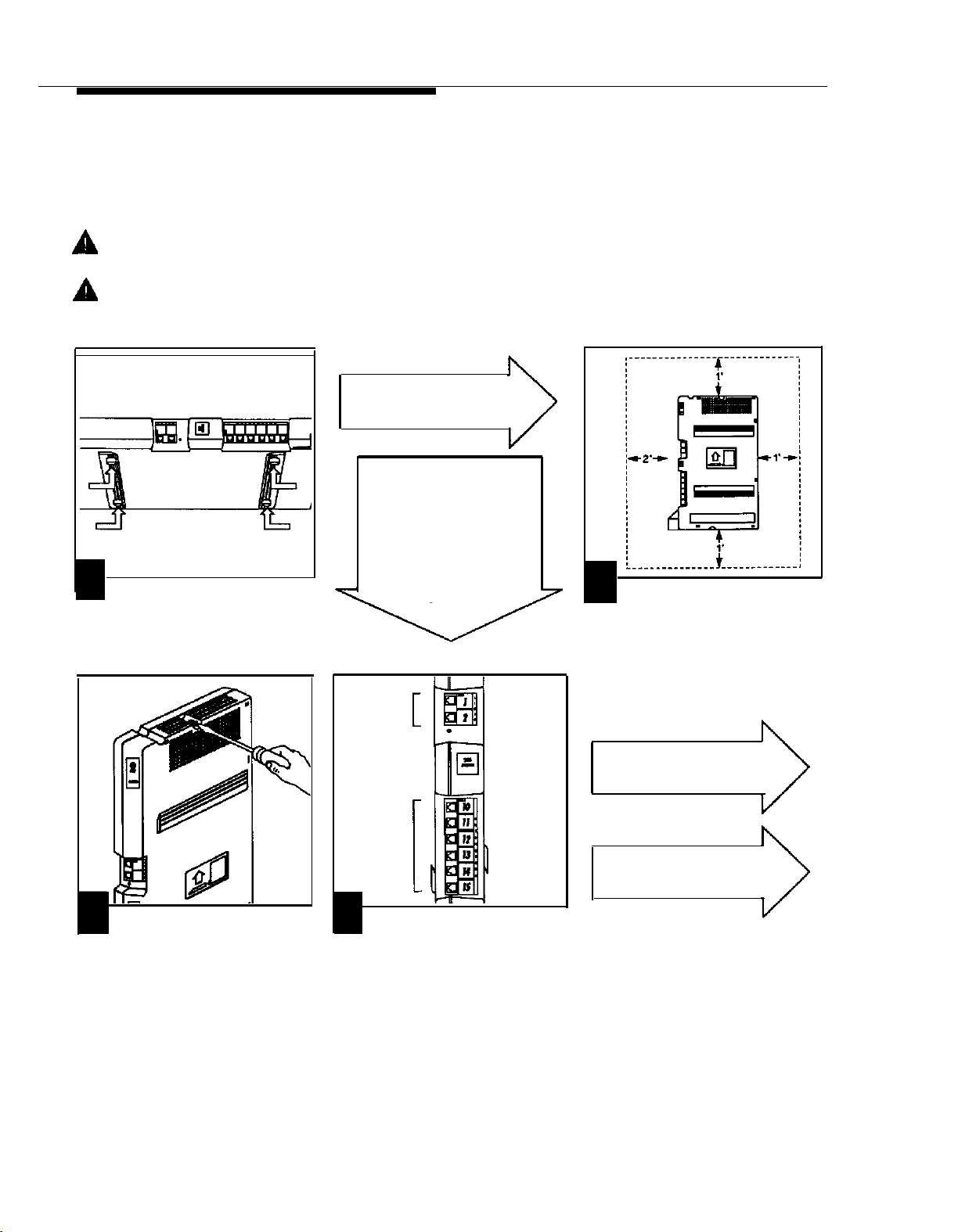
If your PARTNER system has only one mudule, you can install it on a wall or on a flat sturdy surface above the floor
(such as on a table or desk). Wall mounting is recommended. Complete step 1 below and continue as directed.
If your PARTNER system has two modules, you must install it on a wall. Two #12 screws—for mounting the system
■
on a wooden surface—are included with the system. If you are mounting on wallboard, metal, or masonry, use the
proper fasteners for the wall type and weight of the system (approximately 11 Ibs.). Purchase them at any hardware
store. You will also need a screwdriver to mount the system. Complete step 1 below and continue as directed.
■
For testing the system, you will need a standard single-line touch-tone of rotary phone.
CAUTION:
tions must meet the specifications on page 1-6.
CAUTION:
To prevent damage to the system or installation location, the environmental and electrical condi-
Do not connect the AC power cord until the system is fuIIy installed.
Mount the First Module
If you are wall mounting
the system, go to step 2.
If the system has only
one module and you are
installing it on a table,
place the module flat on
the surface with the
rubber feet down. The
module should not slide
easily.
1
Attach the 4 rubber feet to the
mounting tracks on the bottom side of the
module.
Go to step 4.
Lines
2
Hold the 206 module in place on
the wall with the line and extension jacks
facing left. Leave at least 1 foot clearance
at the top, bottom, and back, and at least
2 feat at the front. This allows you to
access the jacks and slide a second
module onto the first, and ensures
adequate ventilation.
3
Insert the screws into the screw
holes at the top and bottom of the module. Tighten until the rubber feet are snug
against the wall. There will be a 3/8" gap
between the wall and the rest of the
module. Do not overtighten—the module
will warp and fail to operate.
2-4
Installing the Hardware
Extensions
4
Label the line and extension jacks
as shown.
If the system has only one
module, go to step 10.
If the system has two
modules, go to step 5.
Page 18
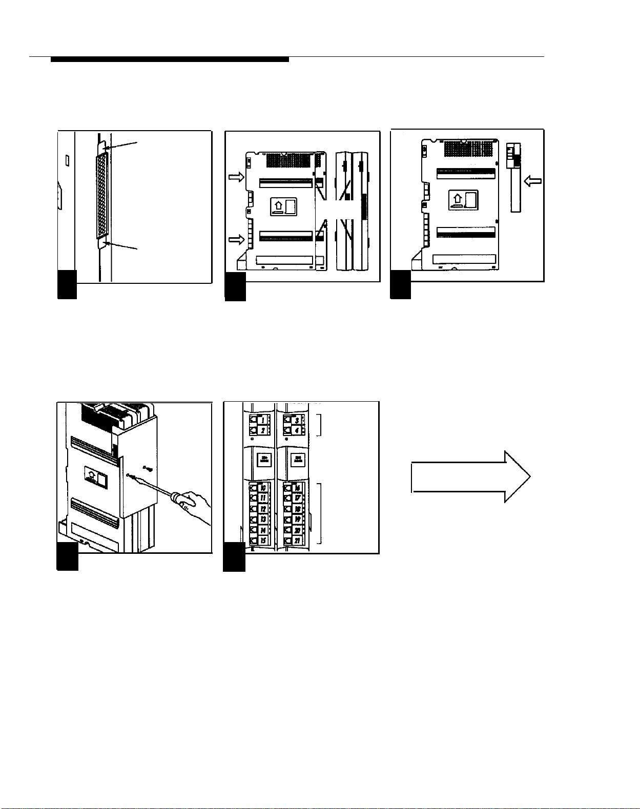
Add the Second Module (for 2-module systems only)
■
A system with two modules must be wall-mounted.
Tab
Tab
5
Remove the plastic protector from
the connectorr on the right side of the
mounted 206 module. Grasp the tabs on
the ends of the protector and lift. If that
module has no plastic protector, check
the other module and remove the
protector.
Front View
6
Slide the second module onto the
first module. Make sure the upper and
lower pairs of mounting tracks interlock,
as shown in the side view above.
Side View
Mounting
Tracks
Lines
7
Attach the module connector to
the top right side of the two modules.
Align the connector carefully and then
push firmly until the connector snaps into
place.
8
Fasten the connector to the
modules using the two screws included
with the connector (the third screw is a
spare).
Extensions
9
Label the line and extension jacks
as shown.
Go to step 10.
Installing the Hardware
2-5
Page 19
Connect Incoming Telephone Lines
Before connecting the telephone company lines, test for dial tone at the network interface jack (step 10).
■
These jacks are the lines from the local telephone company.
If you do not hear a dial tone on one
or more of the incoming lines,
contact your local phone company
and ask a representative to check
the service.
Network
Interface
Jacks
10
To test the incoming telephone
line, connect a standard touch-tone or
rotary phone to the first network
interface jack. Lift the handset and
listen for dial tone.
Repeat for each network interface jack.
12
Route the cords through the
hook below the jacks. Leave 2 feet of
slack to keep the cords from pulling
loose when removing modules.
13
Connect the free end of each line
cord to a network interface jack.
11
Connect the outside line cords to
the line jacks on the module(s). Start
with the jack labeled "1." Continue in
numerical order.
Go to step 14.
2-6
Installing the Hardware
Page 20
Test the System
■
Testing the system includes testing the modules and incoming lines through the modules.
1-Module
System
2-Module
System
14
Make sure the circuit breakers on
each 206 module are pressed down. In
the down position, the top of the circuit
breaker is flush with the top of the
module.
Line Buttons
17
To test the incoming lines, plug a
PARTNER phone into extension 10.
Press the line button for each outside
line and listen for dial tone. lf your
system has two modules, repeat for
extension 16.
15
Connect the AC power cord to
the 206 module on a system with one
module, or to the module connector on
a system with two modules. Press
firmly until it clicks as it locks into
place.
If you do not hear a dial tone for
one or more lines and you have a
1-module system,
Helpline at 1 800 628-2888.
2-module system,
power cord and repeat steps 6 and
7 (p. 2-5) to ensure that the
modules and connector are
properly installed. Test again. If it
still does not work, call the AT&T
Helpline at 1 800 628-2888.
call the AT&T
unplug the
16
Plug the other end of the power
cord into a grounded wall outlet. The
outlet must not be controlled by a
switch.
The green light below the line jacks
on each module should come on. If
not, see chapter 7, “Troubleshooting.” (p. 7-1).
After a successful test,
disconnect the AC power
cord. Go to step 18.
Installing the Hardware
2-7
Page 21
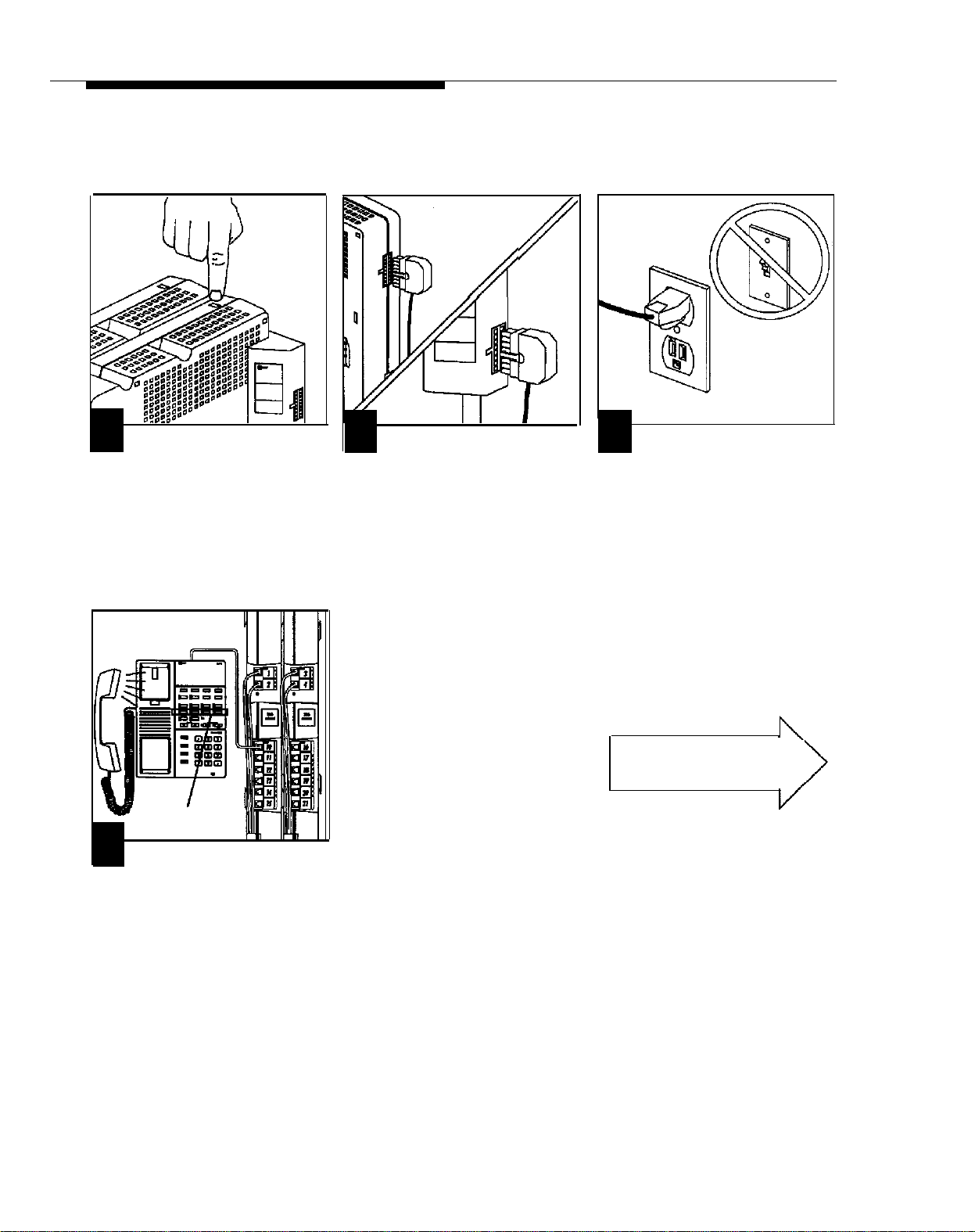
Connect Modular Telephone Cords
CAUTION:
18
Connect the modular telephone
cords for the phones and other equipment to the extension jacks. Start with
the jack labeled “10.” Continue in
numerical order.
Disconnect the AC power cord before continuing.
Connect the Power Cord
19
Route the cords through the hook
below the jacks, Leave 2 feet slack to
keep the cords from pulling loose when
removing modules.
If you are connecting
phones and other equipment directly to the modules, go to step 20.
If you are using the
Extension Wiring Kit for
additional wiring, install
that now. Then go to step
20.
If you are using existing
wiring, connect each cord
to the wiring run jack for
that extension. Then go
to step 20.
20
Make sure the circuit breaker on
each 206 module is pushed in (see step
14). Connect the AC power cord to the
206 module on a system with one
module, or to the module connector on
a system with two modules. Press firmly
until it clicks as it locks into place.
CAUTION:
Do not leave objects (books, cartons, etc.) lying on top of it or resting on its sides.
WARNING:
module connector. Hazardous voltages within. DO NOT OPEN!
2-8
Installing the Hardware
To prevent overheating of the 206 module, do not obstruct the sides.
There are no user-serviceable parts inside the 206 modules or the
21
Plug the other end of the power
cord into a grounded wall outlet. The
outlet must not be controlled by a
switch.
Finish the installation by
connecting telephones
and other equipment.
Page 22
Connecting Equipment
PARTNER Telephones
You can install a PARTNER phone on a desk or wall. Follow the instructions below for desk mounting. For wall
■
mounting, see the next page.
The telephone stand packed with the PARTNER phone is required for wall mounting, optional for desk mounting.
■
To connect a PARTNER phone to the system, use only the 2-pair (4-conductor) telephone cords included with
■
the phone. Use the mounting cord to connect the phone to a wall jack. Or connect the phone directly to a
telephone cord connected to a 206 module.
■
Do not install PARTNER or standard single-line phones out of doors or in a different building from your 206
module(s).
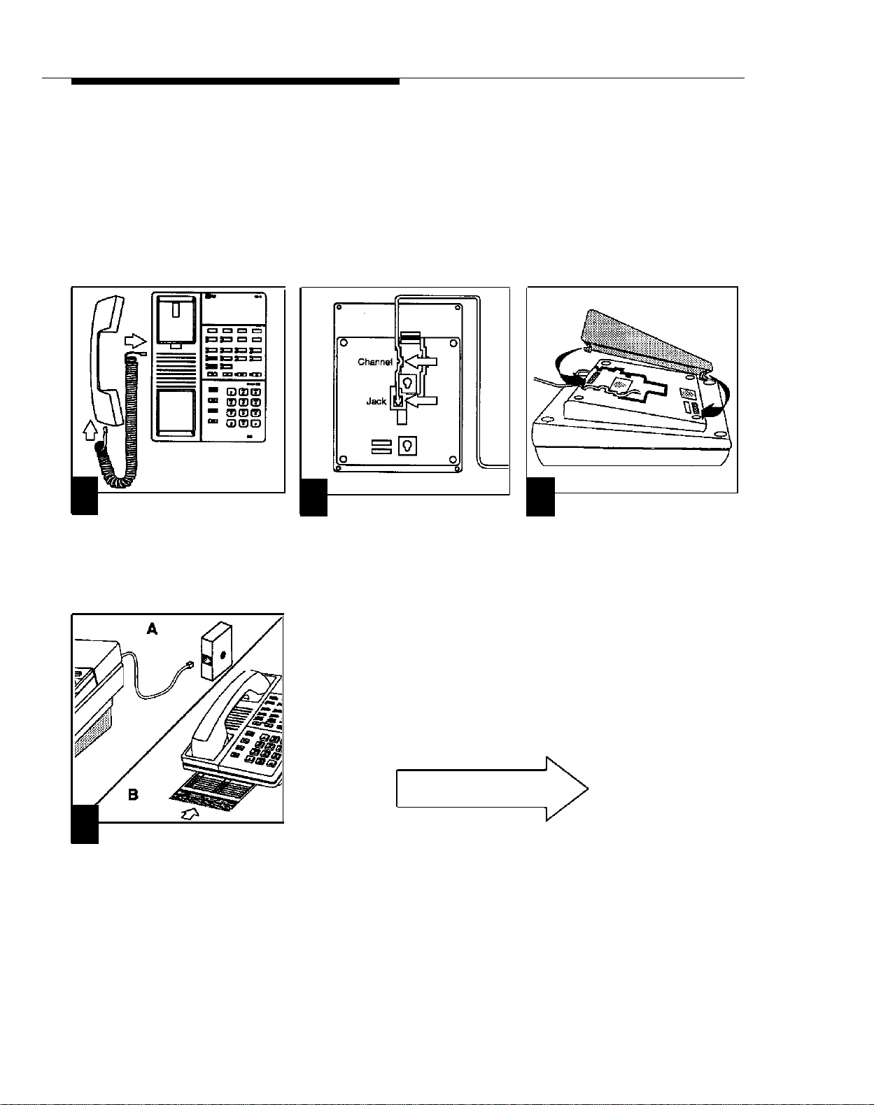
On a Desk:
1
Plug one end of the handset
cord into the jack on the handset. Plug
the other end into the jack on the side of
the phone.
4
A
mounting cord into the modular wall
jack. (Skip this step if connecting the
phone directly to the 206 module).
B
between the “feet” of the phone.
Plug the other end of the
Slide the Quick Reference card
2
Plug the mounting cord (or
telephone cord from a 206 module) into
the jack on the bottom of the phone.
Push the cord into either channel and
out the back end of the phone, so the
phone sits flat without wobbling.
Go to step 7.
3
(Optional) To raise the angle of
the phone, attach the stand to the base
of the phone. Gently place the phone
upside down with the low end of the
phone to the right. Insert the tab on the
narrow end of the stand into the right slot
on the base of the phone. Then insert the
other tab into the left slot, pushing the
stand down and slightly inward until the
tab locks into place.
Installing the Hardware
2-9
Page 23
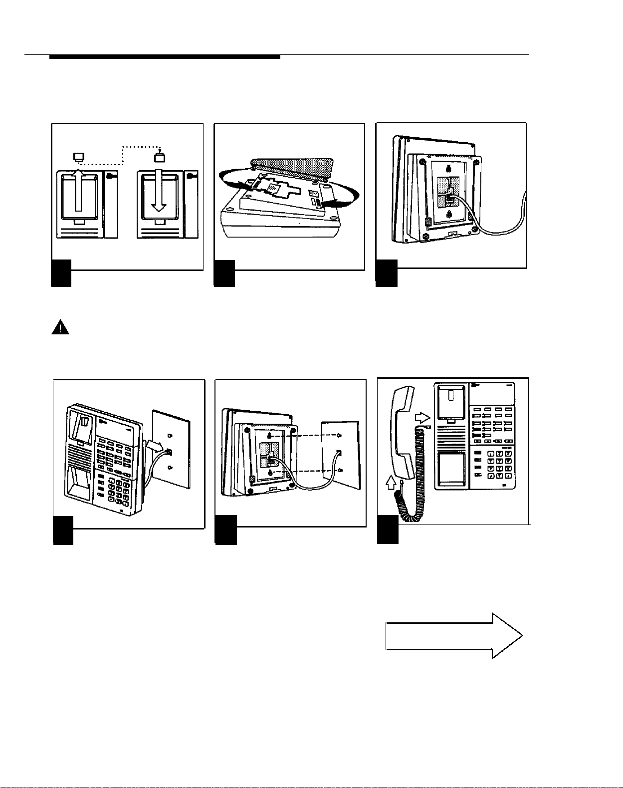
On a Wall:
For a neater mounting, use a shorter, 2-foot mounting cord (AT&T’s D4BU-29). To order, see appendix C.
■
For proper mounting, the wall jack must be an AT&T 630B series connecting or mounting block.
■
1
Reverse the plastic hook that sits
in the earpiece part of the handset
cradle.
CAUTION: Do not attempt
to unscrew the base from the phone.
To do so will expose you to a risk of
electrical shock.
4
Plug the free end of the mounting
cord into the modular wall jack. (Skip
this step if connecting the phone
directly to the 206 module).
2
To attach the stand to the base of
the phone, gently place the phone upside down with the low end of the phone
to the right. Insert the tab on the narrow
end of the stand into the left slot on the
base of the phone. Then insert the other
tab into the right slot, pushing the stand
down and slightly inward until the tab
locks into place.
5
Place the phone/stand assembly
over the wall jack, pushing any excess
cord into the space inside the stand. To
mount the assembly on the wall, place
the screw keyholes on the stand over the
studs above and below the wall jack,
then pull the assembly down gently.
3
Insert the cord through the center
of the stand and plug it into the jack on
the bottom of the phone.
6
Plug one end of the handset cord
into the jack on the handset. Plug the
other end into the jack on the side of the
base. Place the handset in the cradle.
Place the Quick Reference card near the
phone. (You may want to place it on top
of the phone, so the card leans against
the wall.)
2-10
Installing the Hardware
Go to step 7.
Page 24
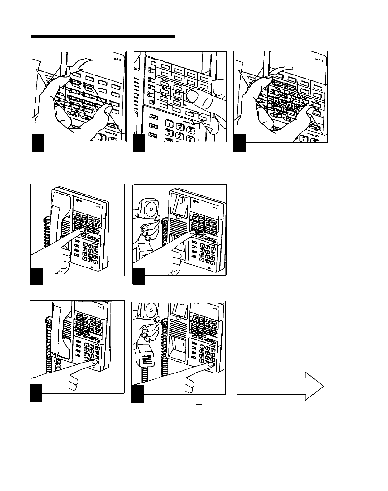
Insert the Button Label Sheet
7
To remove the clear plastic cover Place the button label sheet on
from the phone, gently press down on
the center tab, then lift.
8
the phone. The holes on the sheet
should fit over the buttons.
Test the Connection and Phone
10
To test the outside connection,
press a line button. You should hear an
outside dial tone. Repeat for all lines.
11
To test the intercom, press [
You should hear a system dial tone.
Intercom
9
Replace the plastic cover.
If you don't hear a dial tone for step
10 or 11, see chapter 7, "Troubleshooting" (p. 7-2).
].
12
To test the telephone's lights and
ringer, press and hold [ # ] button for
5 seconds.
13
Before releasing the [ #
lift the handset. All lights should light
and the ringer should sound. Hang up.
] button,
If the lights and/or ringer does not
respond properly, call the AT&T
Helpline at 1 800 628-2888.
Go to next page.
Installing the Hardware
2-11
Page 25
Your PARTNER Communications System should be ready to use. However, if—
■
the system is connected to a PBX or Centrex system, you may need to change certain
system settings. See appendix A.
your local telephone company uses rotary lines instead of touch-tone lines, you must
■
change your system’s Dial Mode from touch-tone to rotary. The procedure is given below:
To change the Dial Mode:
1.
At a PARTNER phone connected to extension 10, press [
The phone beeps once and the light next to the Speaker button is green flutter.
Press the left [
2.
The light next to the
Press [
3.
4.
5.
#
The Message light is steady red if the current setting is touch-tone, flashing red if the current setting is rotary.
Press [
2
If you make a mistake or want to change what you entered, return to step 3.
When you are finished, press [
Intercom
] [
2
] [
0
] [
] button twice.
[
Intercom
1
] .
]
button is steady green.
] to change to rotary, [
1
] to change back to touch-tone.
Feature
] [
0
] [
0
] .
Feature
] [
0
] [
0
] .
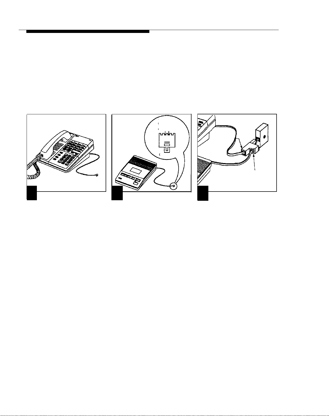
Connecting Standard Single-Line Equipment
Includes rotary, touch-tone, and cordless phones (Iike you might have in your home), fax machines, an-
■
swering machines, modems, credit card verification terminals, and extra alerts (bells, chimes, horns,
strobes, and klaxons).
To connect standard equipment to a wall jack, use 1-pair (2-wire) telephone mounting cords. AT&T rec-
■
ommends D2R mounting cords (see appendix C). To connect standard equipment directly to a 206
module, use 2-pair (4-wire) telephone cords.
1
Assemble the equipment accord-
ing to the manufacturer’s instructions.
2-12
Installing the Hardware
Wall Jack
2
Plug the mounting cord into the
jack on the equipment. Plug the other
end into the modular wall jack.
3
Test the device appropriately.
For example, to test a fax machine,
send a fax to another machine.
If the equipment does not work
correctly, see chapter 7, “Troubleshooting” or the equipment’s
manual.
Page 26
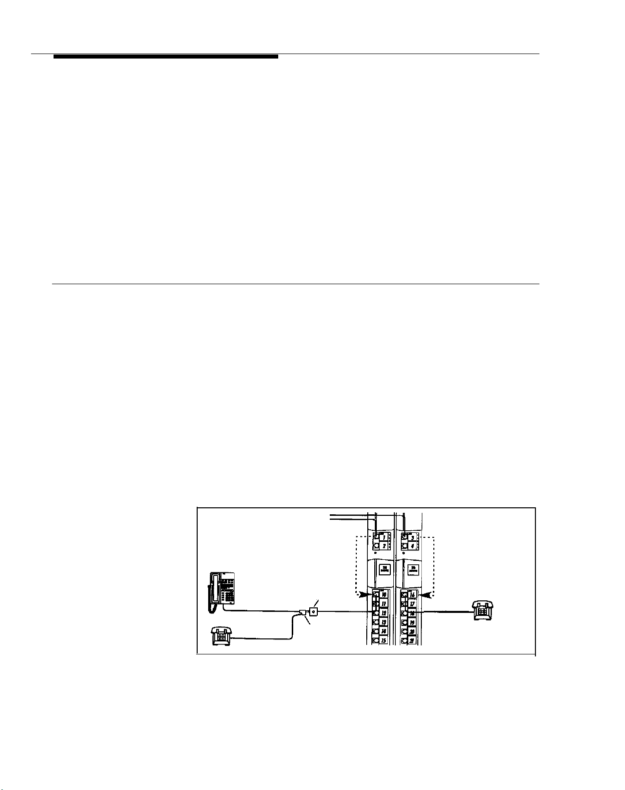
Combining Two Devices
on One Extension
You can combine a PARTNER phone of another standard device or two standard devices on one extension.
■
The total REN (Ringer Equivalence Number) for the devices must be 2 or less (see p. 1-3). Do not combine
two PARTNER phones on one extension jack.
Use only an AT&T 267F2 bridging adapter to combine devices (two included with each 206 module).
■
If the standard device’s mounting cord is loose in the bridging adapter, replace the cord with an AT&T D2R
■
mounting cord (see appendix C).
IMPORTANT:
1
Assemble the PARTNER phone
according to the instructions for desk
mounting (p. 2-9). Attach the mounting
cord included with the phone.
■
Test the PARTNER phone connection by following steps 10 and 11 on page 2-11.
■
Test the other device as appropriate. If it does not work correctly, see chapter 7, “Troubleshooting” or the
Follow these connection instructions instead of those included with the equipment.
Wires in a
1pair-Plug
Green Red
D2 Type Cord
2
Assemble the other device
according to the manufacturer's instructions, except for wiring. Attach a 1-pair
mounting cord to the device (the one
included with the device or an AT&T D2R
cord).
PARTNER
Phone
or
Standard
Device
3
Plug the mounting cord of the standard
device into the jack on the right side of the
267F2 bridging adapter. Plug the
PARTNER phone or second standard
device into the jack on the left side of the
267F2 bridging adpater (the one with four
wires). Plug the adapter into the wall jack
or an extension jack on a 206 module.
Wall Jack
Standard Device
Only
manufacturer’s instructions.
Connecting Other Equipment
In addition to standard equipment, you can connect a variety of headsets and loudspeaker paging systems to the
system. To choose a headset or paging system to meet your needs, call your AT&T representative (or one of the
phone numbers listed on p. 1-4). Follow the instructions provided with the equipment for installation and use.
Installing the Hardware
2-13
Page 27
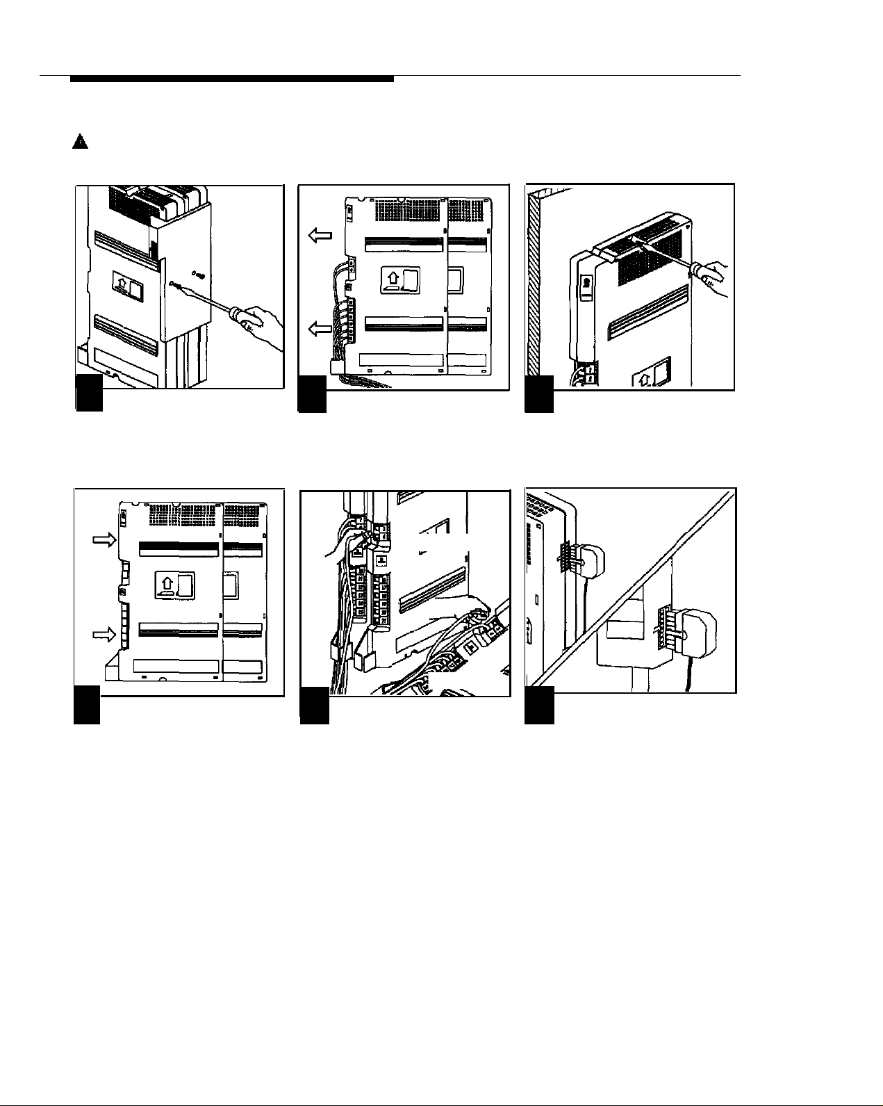
Replacing Modules
■
On a one-module system, follow steps 3-5 below.
■
On a two-module system, start at step 1.
CAUTION:
1
After unplugging the power cord,
remove the screws on the connector.
Pull the connector off the module.
Unplug the AC power cord from the system before starting.
2
Slide off the top module. If replacing that one, go to step 4. If replacing the bottom one, go to step 3.
new module
3
Remove the screws used to
mount the module on the wall.
1-Module
System
2-Module
System
4
Reinstall the module(s) and
connector, as instructed on pages 2-4
and 2-5. Label the new module.
2-14
Installing the Hardware
old module
5
Remove the first line cord of the
old module and connect it to the first
line jack on the new module. Repeat
for the other lines and extensions, one
at a time. (We suggest the "one-at-atime" approach because it’s too easy to
lose track of the wires if you unplug
several at once.)
6
Connect the AC power cord to
the 206 module on a system with one
module, or to the module connector on
a system with two modules. Press
firmly until it clicks into place. If you
unplugged the cord from the wall outlet,
plug it back in at this time.
Page 28

Customizing Your System
Contents
Overview
Changing Factory Settings
■
Outgoing Call Restriction
■
Automatic Line Selection
■ Line Ringing
Abbreviated Ringing
■
Speed Dialing
Auto Dialing
Special Dialing Functions
3
3-1
3-2
3-2
3-3
3-4
3-4
3-5
3-6
3-7
Alphabetical List of Customization Features
Abbreviated Ringing
Auto Dialing
Automatic Line Selection
Call Restriction, Outgoing
Line Ringing
Line Selection, Automatic
Outgoing Call Restriction
Ringing, Abbreviated
Ringing, Line
Speed Dialing
3-4
3-5
3-3
3-2
3-4
3-3
3-2
3-4
3-4
3-5
3-i
Page 29

Overview
After completing the installation steps in chapter 2, your system is fully
operational and ready to go. All the system’s settings are preset and require no
adjustment. However, if you want, you can customize your system to meet your
specific needs by changing some of the factory settings. Following are the
different ways you can customize your system.
■
Outgoing Call Restriction. The system is set up at the factory to allow all
phones to make all calls. However, you can prevent any telephone from
making an outside call. A restricted phone can only make intercom (inside)
calls. This can help you control unauthorized phone activity and keep costs
down. See p. 3-2.
Automatic Line Selection. When you lift a phone’s handset, normally the
■
system automatically connects you to an available outside line. The system
is set at the factory to connect you automatically to outside line 1. If line 1 is
busy, then you are connected to line 2; if line 2 is busy, you are connected to
line 3; and so on. If all the outside lines are busy, you will be connected to
an intercom (inside) line. Automatic Line Selection allows you to change the
sequence of lines to which a user is automatically connected. For examples
of situations when you might want to change the Automatic Line Selection,
and for instructions on how to do it, see p. 3-3.
Line Ringing. The system comes set up so that each line on all phones ring
■
when a call comes in. You can, however, set up a line or lines on a
PARTNER phone so they do not ring. (Even though the phone doesn’t ring,
you can tell a call is coming through by the flashing lights next to the line
buttons.) If the phone is set up not to ring, you can still answer the call. See
p. 3-4.
■
Abbreviated Ringing. Normally, when you are busy on a call, an incoming
call will ring out loud once, and then stop ringing while the green light next to
the line or intercom button continues to flash. You can change this so that a
phone continues to ring until it is answered. See p. 3-4.
Speed Dialing. The system can store up to 10 outside numbers that users
■
can dial by pressing only three buttons. You might want to store numbers of
business associates, suppliers—any numbers that the people who use your
system dial all the time. See p. 3-5.
Auto Dialing. Anyone with a PARTNER 12-button phone can store up to
■
eight additional outside numbers that can be dialed with a single touch. See
p. 3-6 and 4-4.
Customizing Your System
3-1
Page 30

Changing Factory Settings
The system’s factory settings can be changed only from extension 10 using a
PARTNER phone. You can change settings anytime, even when you are on a
call. This allows you to change settings while talking on the AT&T Helpline. Just
remember that (except for Auto Dialing) you must change settings from extension 10 using a PARTNER phone.
Step-by-step instructions are given below for each setting.
Outgoing Call Restriction
An extension can be either unrestricted (can make inside and outside calls) or
restricted (can only make inside calls).* The restrivted setting is used for telephones in reception areas or other public rooms where you want to prevent anyone from making outgoing calls. It is also useful for prohibiting calls from warehouse extensions, or from extensions that are used to take phone orders. The
factory setting is unrestricted for all extensions, so change the setting only to
restrict certain extensions from making outside calls.
Procedure:
1.
Press [
Feature
] [
0
] [
0
].
The phone beeps once, the lights of the four line buttons no longer show the
status of the lines, and the light next to the [
Press the left [ Intercom ] button twice.
2.
The light next to the button is green steady.
Press [
#
] [
4
] [
0
] [
1
3.
4.
Dial the 2-digit number (10 to 21) of the extension you want to change.
The Message light is steady red if the current setting for the extension is "no restriction," flashing red if the current setting is "restricted."
Press [ 1 ] for “no restriction,” or [ 2 ] for “restricted.” If you make a mistake
5.
].
Spkr ] button is green flutter.
or want to change the setting, return to step 3. To change the setting at
another extension, return to step 3.
When you are finished, press [
6.
*
While procedures that restrict dialing are very effective, absolute protection against misuse cannot be guaranteed. PARTNER
phones give more protection than standard phones. Therefore, we strongly recommend that you install PARTNER phones
where restricting phone use is important.
Feature ] [ 0 ] [ 0 ].
3-2 Customizing Your System
Page 31

Automatic Line Selection
If you have a two-module system with four lines, the system is set at the factory
to connect you automatically to lines in the following order: Outside Line 1, 2, 3,
4, Intercom. If you have a system with one 206 module, the system connects
you in the following order: Outside Line 1,2, Intercom. That is, when you lift the
handset, the system will automatically connect you to Line 1. If Line 1 is busy,
then you are connected to Line 2; if Line 2 is busy, to Line 3, and so on. If all the
outside lines are busy, you are connected to the intercom (inside) lines. Change
this setting only if you want to change the order of the lines to which a user is
automatically connected. You can set any possible order, such as 4, Intercom,
1,3,2.
The following examples may help you identify extensions in your business for
which you should change the Automatic Line Selection:
■
■
If you have a standard single-line touch-tone or rotary phone connected to
an extension, change the line sequence from Line 1, 2, 3, 4, Intercom to
Intercom, Line 1, 2, 3, 4. This makes it easy for the person at the standard
phone to make an intercom call. To make an outside call, he or she only has
to dial [
9 ], then the number. For more information about how to use standard
phones with the PARTNER system, see chapter 5.
If a person with a PARTNER phone makes a lot of intercom calls, but rarely
makes outside calls, you might change the order at that person’s extension
to Intercom first. Therefore, when that person lifts the handset, he or she will
be connected to an Intercom line automatically.
If your system has three outside lines, you must remove Line 4 from the
■
Automatic Line Selection sequence for all extensions. For example, you
might change the sequence to Outside Line 1, 2, 3, Intercom.
Procedure:
1.
Press [
Feature
] [
0
] [
0
].
The phone beeps once, the lights of the four line buttons no longer show the
status of the lines, and the light next to the [
2.
Press the left [ Intercom ] button twice.
The light next to the button is green steady.
3.
Press the right [ Intercom ] button.
Dial the 2-digit number (10 to 21) of the extension you want to change.
4.
Press [
5.
Press the line buttons in the order you want them to be automatically
6.
selected. Press the left [
When your sequence is complete, press [
7.
✼
] [
✼
].
Intercom ] button to select Intercom.
Spkr ] button is green flutter.
✼ ] [ ✼ ]. If you want to correct a
mistake, or change the line order for another extension, return to step 3.
8.
When you are finished, press [
Feature
] [
0
] [
0
].
Customizing Your System 3-3
Page 32

Line Ringing
If you want to set up your system
so that all incoming calls come
through a receptionist, you
would change the setting so the
other phones do not ring.
Line Ringing lets you set all, some, or no outside lines to ring on each individual
extension. The factory setting is for each outside line to ring on all extensions.
Change this setting if you want one or more lines on any extension not to ring.
Procedure:
Press [
Feature
] [
0
] [
0
1.
The phone beeps once, the lights of the four line buttons no longer show the
status of the lines, and the light next to the [
2.
Press the left [ Intercom ] button twice.
The light next to the button is green steady.
Press the right [ Intercom ] button.
3.
4.
Dial the 2-digit number (10 to 21) of the extension you want to change.
The light next to each line button is steady green if the setting is for “ring;” green
flutter if the setting is for “no ring.”
If you want to change the setting for any line at that extension, simply
5.
].
Spkr ] button is green flutter.
press the line button. To change the setting for another extension, return
to step 3.
The light changes to show the setting.
Abbreviated Ringing
Receptionists and others who
handle many calls prefer to turn
Abbreviated Ringing off so that
they can be reminded of
unanswered calls.
When you are finished, press [
6.
Feature
] [
0
] [
0
].
The system comes set up so that when an incoming call rings at a busy phone,
it will ring once and then stop ringing while the green light next to the line or
intercom button continues to flash. Turn Abbreviated Ringing "off" if you want
a phone to continue to ring until it is answered.
Procedure:
Press [
1.
The phone beeps once, the lights of the four line buttons no longer show the
status of the lines, and the light next to the [
Press the left [ Intercom ] button twice.
2.
The light next to the button is green steady.
Press [
3.
Dial the 2-digit number (10 to 21) of the extension you want to change.
4.
The Message light is steady red if Abbreviated Ringing is “on;” red flash if it is
"off."
5.
Press [ 1 ] to turn on Abbreviated Ringing, or press [ 2 ] to turn off Abbrevi-
Feature
#
] [
3
] [
] [
0
0
] [
] [
5
0
].
Spkr ] button is green flutter.
].
ated Ringing. If you make a mistake or want to change the setting, return
to step 3.
The light changes to show the setting.
3-4 Customizing Your System
When you are finished, press [
6.
Feature
] [
0
] [
0
].
Page 33

Speed Dialing
All system users should get a
copy of the Speed Dial form in
appendix B.
To dial the Speed Dial number, a
user simply presses [
the 2-digit code.
Feature ] and
Speed Dialing allows you to store up to 10 outside numbers in the system’s
memory. Any user can dial these numbers automatically by pressing only three
buttons. Speed Dialing saves time and effort, and can spare people from constantly looking up telephone numbers. Appendix B provides a form on which to
list the Speed Dial numbers.
You can use Speed Dialing to dial automatically certain numeric sequences
other than regular telephone numbers. For example, some banks and financial
services allow you to transact business over the telephone. After dialing the
call, you are usually requested to enter your account number by pressing the
numbers on the dialpad. These additional numbers can be included in the
Speed Dial number.
You can also include the Pause, Stop, Touch-Tone Enable, and Recall functions
in a Speed Dial number. See p. 3-7 for instructions.
To store a Speed Dial number (from extension 10):
1.
Press [
Feature
] [
0
] [
0
].
2.
Press [ Feature ], then press the 2-digit code between 20 and 29 that you
want to assign to the Speed Dial number.
You can also use this procedure
to program a new Speed Dial
number over another one already
assigned to a 2-digit code. Simply enter the new number.
You must use a PARTNER 12button phone at extension 10 to
remove a Speed Dial number
from memory.
3.
Enter the Speed Dial number (up to 20 digits long). (If you want to include
special functions in the number, such as Pause, Stop, Touch-Tone Enable,
or Recall, see p. 3-7.) To store another Speed Dial number, return to
Step 2.
Feature
] [
0
] [
0
When you are finished, press [
4.
].
IMPORTANT: When programming and/or testing emergency numbers (such
as 911 or other emergency services):
1.
Remain on the line and briefly explain to the dispatcher the reason for the
call before hanging up.
2.
Perform such activities during the off-peak hours, such as early morning or
late evening.
To remove a Speed Dial number from memory (from extension 10):
1.
Press [
Press [ Feature ], then press the Speed Dial number’s 2-digit code.
2.
Press [
3.
When you are finished, press [
4.
Feature
] [
0
] [
0
].
Mic ]. To remove another number, return to step 2.
Feature ] [ 0 ] [ 0 ].
Customizing Your System
3-5
Page 34

Auto Dialing
With Auto Dialing, anybody with a PARTNER 12-button phone can store up to
eight outside phone numbers on Auto Dial buttons. This allows the number to
be dialed with a single touch. Any user can store Auto Dial numbers on his or
her phone. Or, you can work at extension 10 to store Auto Dial numbers on
other phones.
Like Speed Dial numbers, Auto Dial numbers can include numeric sequences
and special functions.
To store an Auto Dial number at
an individual phone, see p. 4-4.
You can also use this procedure
to store a new Auto Dial number
over another one already
assigned to a button.
To dial and Auto Dial number,
simply press the Auto Dial button.
To store an Auto Dial number on another extension (from extension 10):
Press [
1.
Press the left [ Intercom ] button twice.
2.
Press the right [
3.
Dial the 2-digit extension on which the number will be stored.
4.
Ext. 10 now functions as if it were the extension on which the number will be
stored.
Press the button to which you want the Auto Dial number assigned. (Auto
5.
Feature
] [
0
] [
0
].
Intercom ] button.
Dial buttons are shown on p. 4-1.)
Dial the outside number, maximum 20 digits. (To include the Pause, Stop,
6.
Touch-Tone Enable, or Recall functions, see p. 3-7.) To store another
number on the same extension, return to step 5. To store a number on a
different extension, return to step 3.
When you are finished, press [
7.
Feature ] [ 0 ] [ 0 ].
IMPORTANT: When programming and/or testing emergency numbers (such
as 911 or other emergency services):
1.
Remain on the line and briefly explain to the dispatcher the reason for the
call before hanging up.
2.
Perform such activities during the off-peak hours, such as early morning or
late evening.
You must use a PARTNER 12button phone at extension 10 to
remove an Auto Dial number from
another phone.
3-6 Customizing Your System
To remove an Auto Dial number from any extension (from extension 10):
1.
Press [
Feature
] [
0
] [
0
].
Press the left [ Intercom ] button twice.
2.
Press the right [
3.
Dial the 2-digit number of the extension on which the number is stored.
4.
Ext. 10 now functions as if it were the extension on which the number is stored.
Press the button from which you want the Auto Dial number removed.
5.
Press [
6.
7.
Mic
To remove another number from the same extension, return to step 5. To remove
a number from another extension, return to step 3.
When you are finished, press [ Feature ] [ 0 ] [ 0 ].
Intercom ] button.
].
Page 35

Special Dialing Functions
You can add these special functions to any Auto Dial or Speed Dial number:
■
Pause. A pause causes the dialing sequence to stop for 1.5 seconds. You
might need a pause when dialing into a different long distance service or
when dialing an international number. You can insert as many pauses as
needed. For example, if you want to dial your answering machine at home,
and then automatically dial its message retrieval code, you would enter your
auto dial number like this: 201 555 1234 [pause] [pause] [pause] 321.
If you use Recall, it must be the
first entry in the sequence.
You can only insert a Stop from a
PARTNER 12-button phone.
Do not enter a Stop as the first
character in a sequence. This
would remove the Auto Dial or
Speed Dial number.
Summary
To insert a . . . Press . . .
Pause
Recall
Stop
Touch-Tone Enable
[
Hold
[
Spkr
[
Mic
[
Transfer
]
]
]
To insert a pause, press [
Hold ] while storing an Auto Dial or Speed Dial
number.
Recall. If your PARTNER system is connected to a PBX or Centrex system,
■
the recall signal activates many features in the PBX or Centrex system. For
example, you could program a dialing sequence to turn on its Call Waiting
feature with a single touch. Such a sequence might look like this: [recall]
123.
To insert Recall, press [ Spkr ] while storing an Auto Dial or Speed Dial
number.
■ Stop. A stop inserted into a dialing sequence allows you to stop, wait for a
response, and then continue the sequence. For example, there are some
banking services that let you do business over the phone by dialing a
number, waiting for an answer, and then entering your account number. You
can create a dial sequence that first dials the bank’s number and then stops.
After the call is answered, press the Auto Dial button or redial the Speed Dial
code to continue the sequence to automatically dial your account number.
The sequence would look like this: 555 1234 [stop] 54327.
To insert a stop, press [
■ Touch-Tone Enable. If your system has rotary dialing, you can turn on
Mic ] while storing an Auto Dial or Speed Dial number.
touch-tone dialing automatically in the dialing sequence. For example, if you
call your telephone banking service and need to enter your account number
from a touch-tone phone, you could build Touch-Tone Enable into the dialing
sequence. The sequence would look like this: 555 1234 [touch tone enable]
[pause] 54321. (Note that this sequence combines Touch-Tone Enable with
the Pause function described above.)
To insert Touch-Tone Enable, press [
Transfer ] while storing an Auto Dial or
Speed Dial number.
Remember, you can use Pause, Stop, Touch-Tone Enable, and Recall in any
]
Speed Dial or Auto Dial number. And, you can combine them any way you want
(except where otherwise noted).
Customizing Your System
3-7
Page 36

Basic Call Handling with PARTNER Phones
Contents
4
PARTNER Phone Controls
■
Lights
■
Ringing Patterns
■
Using the Speaker and Microphone
Hands-Free Answer on Intercom (HFAI)
Using the Auto Dial Buttons
Call Handling
■
Using the Speakerphone
■
A Word about Dial Tones
■
Making an Outside Call
■
Making an Intercom Call
■
Answering a Call
■
Putting a Call on Hold
Transferring a Call
■
Making a Conference Call
■
Joining a Call
■
Built-In Calling Features
4-1
4-2
4-2
4-3
4-3
4-4
4-5
4-5
4-5
4-6
4-6
4-7
4-7
4-8
4-9
4-10
4-11
4-i
Page 37

PARTNER Phone Controls
Figure 4-1 shows the buttons and indicators on the PARTNER 12-button
telephone. (The PARTNER 6-button telephone is not shown. It is the same as
the PARTNER 12-button phone except that it has no Auto Dial buttons, Calling
Feature buttons, or built-in microphone.)
Calling Feature Buttons
(12-button phone only)
These four buttons, from left to right, are pressed to
use the following features: Privacy, Last Number
Redial, Recall, and Conference Drop. For descriptions
of what these features are, and how to use them, see
p. 4-11.
Intercom Buttons
Press either button to make or answer an inside
(intercom) call to another extension.
Feature Button
Press to change system settings, dial Speed Dial
numbers, and, on a PARTNER 6-button phone, use
Calling Features.
Conf (Conference) Button
Press to add other parties to your call (see p. 4-9).
Transfer Button
Press to transfer a call to another extension (see p. 4-8).
Hold Button
Press to put a call on hold for later pickup (see p. 4-7).
AT&T
MLS-12
Auto Dial Buttons
(12-button phone only)
Stores Auto Dial numbers for dialing with one-touch
(see p. 4-4).
Line Buttons
Press to make or answer outside calls. Green and red
lights next to each button sho
the line (see p. 4-2).
W
what is happening on
Spkr (Speaker) Button
Press to dial without lifting handset. With the speaker
on, the green light appears and you can hear what is
being transmitted from the other end. When the party
answers, lift the handset to talk. (Users with 12-button
phones can press [
Mic ] to talk).
Mic (Microphone) Button
(12-button phone only)
Press to talk without lifting the handset. With the
micrcphone on, the green light appears and the
person on the other end can hear you.
Message Indicator
Flashes to show settings while programming.
Volume Control Buttons
Press to decrease ( ∇ ) or increase ( ∆ ) the volume
of the ringer, speaker, and handset.
❑
To adjust ringer volume, while phone is idle and
handset is on the phone, press ∇ or ∆.
❑
To adjust speaker volume, press ∇ or ∆ while
listening through the speaker.
❑
To adjust handset volume, while listening on a call,
lift handset and press ∇ or ∆.
Figure 4-1 PARTNER 12-Button Telephone Buttons and Indicators
Basic Call Handling with PARTNER Phones
4-1
Page 38

Lights
These light patterns apply only
for buttons that have lines
assigned to them. Lights for
unused buttons are always off.
Light patterns are different when
changing system settings.
To the left of each line and intercom button is a green and a red light. These
lights flash in different ways to show what is happening on that line. The green
light shows activity at your extension; the red light shows activity at other extensions. The following examples use a broken line to illustrate the various light
patterns.
■
Steady On
A steady on light means a busy line. When the green light is on, your telephone is busy on that line. When the red light is on, another extension is
busy on that line.
■
Off (off continuously)
An off light means the line is idle.
■
Flash
A flash pattern (long off, long on) means a call is ringing. When the green
light flashes, a call is ringing on that line at your extension. When the red
light flashes, it means that the line is ringing, but not at your extension.
Alternating Red/Green Flash
■
An alternating red and green flash (red on, green on, red on, green on)
appears on both extensions on a joined call. It also appears on an extension
connected in a conference call.
Ringing Patterns
A transferred call will ring like an
intercom call (Ring-BEEP) until
the person transferring the call
hangs up, at which time the call
will ring like a transferred call
(Ring-BEEP-BEEP).
■
Wink
A wink pattern (long on, short off) shows a call on hold. When the green light
winks, a call is on hold at your extension. When the red light winks, a call is
on hold at another extension.
■
Flutter
A flutter pattern (short on, short off) shows a conference call on hold.
These light patterns are mentioned throughout this guide.
You can tell what kind of call you are receiving by the way your telephone rings.
A single ring (Ring . . . Ring . . . Ring . . .) means you are receiving an out-
■
side call.
■
A ring and a beep (Ring-BEEP . . . Ring-BEEP . . . Ring-BEEP . . .) means
you are receiving an intercom (inside) call.
A ring and two beeps (Ring-BEEP-BEEP . . . Ring-BEEP-BEEP . . . Ring-
■
BEEP-BEEP . . . ) means you are receiving a transferred call.
Standard single-line rotary and touch-tone phones ring differently. See
chapter 5.
4-2 Basic Call Handling with PARTNER Phones
Page 39

Using the Speaker and Microphone
Both PARTNER telephones have a speaker, which you can turn on by pressing
Spkr ]. The PARTNER 12-button telephone also has a microphone, which you
[
When the green light next to the button is on, the
can turn on by pressing [
speaker or microphone is on.
With the PARTNER 12-button phone, you can make and answer calls without lifting the handset by turning both the speaker and the microphone on. When you
turn on the speaker, you will hear a dial tone. When the microphone is on, turning the speaker on and off is the same as lifting and replacing the handset.
On the PARTNER 6-button phone, you can turn on the speaker to get a dial
tone, dial the call, and hear the call ringing. When the other party answers, you
must lift the handset to talk since you do not have a microphone button.
You can switch from the handset to the speaker and microphone by pressing
Mic ] and then [ Spkr ] and hanging up the handset. To go from the speaker and
[
microphone to the handset, lift the handset.
Hands-Free Answer This feature allows users with PARTNER 12-button phones to automatically
on Intercom (HFAI)
answer a voice-signaled intercom call. If you leave the microphone on all the
time, you can respond to a voice-signaled intercom call without lifting the
handset. The incoming voice-signaled intercom call will automatically turn on
your speaker. This is called Hands-Free Answer on Intercom. If the microphone is on and an outside call comes in, press [
Mic ].
Spkr ] to answer the call.
Basic Call Handling with PARTNER Phones
4-3
Page 40

Using the Auto Dial Buttons
Anyone with a PARTNER 12-button telephone can use the Auto Dial buttons
(shown in figure 4-1) to personalize his or her phone. See p. 3-6 for instructions
on how to store an Auto Dial number while working from extension 10.
To store an Auto Dial number:
1.
Press [
2.
You can also use this procedure
to store a new Auto Dial number
over another one already
assigned to a button. Simply
enter the new number.
Press the button to which you want the Auto Dial number assigned.
3.
Dial the number, entering a maximum of 20 digits including special functions. (To insert special functions into the number, such as Pause, Stop,
Touch-Tone Enable, or Recall, see p. 3-7.) To store another Auto Dial
number, return to step 2.
Feature
] [
0
] [
0
].
You can dial an Auto Dial number
while on an outside call. For
example, you can do this to dial
an account number for an
automatic banking service. However, you cannot dial an Auto Dial
number while on an intercom call.
4.
When you are finished, press [
Feature ] [ 0 ] [ 0 ].
IMPORTANT: When storing and/or testing emergency numbers for Auto
Dialing (such as 911 or other emergency numbers):
1.
Remain on the line and briefly explain to the dispatcher the reason for the
call before hanging up.
2.
Perform such activities during the off-peak hours, such as early morning or
late evening.
To remove an Auto Dial number from memory (PARTNER 12-button phone
only):
1.
Press [
Press the button from which you want a number removed.
2.
3.
4.
To dial an Auto Dial number:
Press the Auto Dial button on which the number is stored.
1.
A line is automatically selected, the speaker comes on, and the Auto Dial
number dials automatically. If you do not care to use the speakerphone,
lift the handset.
If you want to call on a specific line, press the line button before pressing the
Auto Dial button.
Feature
] [
0
] [
0
].
Press [ Mic ]. To remove another number, return to step 2.
When you are finished, press [
Feature
] [
0
] [
0
].
4-4 Basic Call Handling with PARTNER Phones
Page 41

Call Handling
In this section you will learn how to handle calls using PARTNER phones, and
how to use the system’s built-in calling features. The information given here is a
more detailed version of the information on the Quick Reference. We recommend that you read this chapter first, and then use the Quick Reference as a
reference.
For instructions on using standard single-line touch-tone, rotary, or feature
phones, see chapter 5.
Using the Speakerphone
A Word about Dial Tones
The procedures in this section instruct you to use the handset to make and
answer calls. However, if you prefer to dial and talk on calls without lifting the
handset, you can use the speaker and the microphone instead. If you have a
PARTNER 12-button telephone, leave the microphone on all the time. When you
want to make or answer a call (or when the instructions tell you to lift the
handset), simply use the speaker. If you receive a voice-signaled intercom call
while your microphone is on, you will hear the caller’s voice and be able to
answer without lifting the handset or turning the speaker on. For more information, see p. 4-3.
You hear two different dial tones when making calls:
■
An outside line dial tone comes from your local phone company. When
you hear an outside line dial tone, you are connected to an outside line.
■
An intercom dial tone comes from the PARTNER system. When you hear
an intercom dial tone, it means that you are connected with an inside line,
which is used to make inside, or intercom, calls.
It is important that you hear the difference between the two types of dial tones.
The best way to do this is to listen to each one and compare the two. To hear
an outside line dial tone, lift the handset, and press a line button. To hear an
intercom dial tone, press either [
Intercom ] button.
Basic Call Handling with PARTNER Phones
4-5
Page 42

Making an Outside Call
If you lift the handset before
pressing an outside line button,
you will be automatically con-
nected to the first idle line. The
sequence of idle lines to which
you are connected is determined
by the "Automatic Line Selection"
feature. See p. 3-3.
To make an outside call:
1.
Press any idle line button. (An idle line button is one that is not lit.)
The light next to the line button is steady green.
2.
Lift the handset.
3.
Dial the number.
To dial a Speed Dial number:
1.
Press [ Feature ] plus the 2-digit speed dial code (20 to 29).
The number dials automatically.
2.
Lift the handset.
To dial a call on a specific line, press the line button first.
To store a Speed Dial number (which must be done at extension 10), see p. 3-5.
To dial an Auto Dial number:
1.
Press the Auto Dial button on which the number is stored.
A line is automatically selected, the speaker comes on, and the Auto Dial number
dials automatically. If you do not care to use the speakerphone, lift the handset.
Auto Dial button.
To store an Auto Dial number on a button, see p. 4-4.
Making an Intercom Call
An inside call, or intercom call, is a call to another extension in the PARTNER
system. When you make an intercom call, there are two ways that you can signal the extension you are calling: by ringing or by voice. A ringing intercom call
causes the called telephone to ring. A voice-signaled intercom call causes the
called extension to beep. After it beeps, the caller can speak, and the caller’s
voice will be heard on the called extension’s speaker.
To make a ringing intercom call:
If you want to call on a specific line, press the line button before pressing the
1.
Press either [
The light next to the [ Intercom ] button is green steady.
2.
Lift the handset.
You hear the intercom dial tone.
3.
Dial the 2-digit extension number.
Intercom
] button.
4-6 Basic Call Handling with PARTNER Phones
Page 43

If you have a PARTNER 12-
button phone, and you leave the
microphone on all the time, you
can answer a voice-signaled
intercom call without lifting the
handset. Be a ware that after
your phone beeps, the caller can
hear through your phone’s microphone.
Answering a Call
If a call comes in on a line that
has been set up for “no ring,” the
call will appear as a flashing red
light, but you will not hear it ring.
To answer the call, press the line
button and lift the handset.
To make a voice-signaled intercom call (to another PARTNER phone only):
1.
Press either [ Intercom ] button.
Lift the handset.
2.
The green light appears and you hear the intercom dial tone.
Press [ ✼ ] and the 2-digit extension number. After you hear a short beep,
3.
speak into the handset.
Your voice is heard on the other extension’s speaker. If the extension you are trying to call is busy, or if it is a standard phone, the phone will simply ring.
To answer a voice-signaled intercom call:
Lift the handset (or press [
1.
Mic ] if you have a PARTNER 12-button phone).
To answer a call:
1.
Press line button next to the flashing green light.
Lift the handset.
2.
You are connected to the incoming call. If more than one line is ringing, simply lift
the handset and you will be connected to the line that has been ringing longest.
To answer a call ringing on a specific line (more than one line ringing):
1.
Press the line button for the line you want to answer.
2.
Lift the handset.
You are connected to the incoming call.
Putting a Call on Hold
A user is free to make and
receive other calls while a call is
on hold.
Only one party at a time can put
an intercom call on hold. If both
parties try to put the call on hold,
the call will be disconnected.
You can hold both outside calls and intercom calls. However, an intercom call
on hold can only be picked up at the extension where it was put on hold.
To put an outside or intercom call on hold:
Press [
1.
The light next to the line button winks green. Other extensions see a winking red
light on held outside calls.
Hold
].
To retrieve a call from hold:
1.
Press the line button on which the call is held.
The light next to the line button changes from winking to steady green.
Lift the handset.
2.
Basic Call Handling with PARTNER Phones 4-7
Page 44

Transferring a Call
A transferred call will ring like an
intercom call (Ring-BEEP) until
the person transferring the call
hangs up, at which time the call
will ring like a transferred call
(Ring-BEEP-BEEP).
To transfer a call means to pass the call from one phone to another. You can
only transfer outside calls; you cannot transfer intercom calls. There are three
ways to transfer a call:
Announce the call when it is picked up.
■
■
Announce the call through the speaker.
■
Transfer the call with no announcement.
To transfer a call with an announcement:
You can only announce a call
through the speaker of a
PARTNER phone. If it is busy, or
if it is a standard phone, it will
ring instead.
1.
While active on a call, press [
You hear the intercom dial tone. The call is put on hold and its associated light
winks green.
2.
Dial the 2-digit number of the extension to which you want the call
Transfer ].
transferred.
When someone answers, announce the call. If the call is accepted, hang
3.
up. If no one answers or the call is refused, press the held line button next
to the winking light and you are reconnected with the caller.
To transfer a call with announcement over the speaker:
1.
While active on a call, press [ Transfer ].
You hear the intercom dial tone. The call is put on hold and its associated light
winks green.
Dial [ ✼ ] plus the 2-digit number of the extension to which you want the call
2.
transferred.
Announce the call.
3.
The other party’s speaker is automatically turned on, and your voice is heard on it.
The other party can pick up the call by pressing [
4.
If you hang up and the party does not pick up the call, press the held line
Mic ] or lifting the handset.
button next to the winking light and you are reconnected with the caller.
To transfer a call with no announcement:
Another way to transfer an outside call is to put it on hold, and
then have another user pick the
call up at another extension by
pressing the line button (they see
it as winking red) of the held call.
1.
While active on a call, press [
You hear the intercom dial tone. The call is put on hold.
2.
Dial the 2-digit number of the extension to which you want the call
transferred.
Hang up.
3.
If no one answers, you can retrieve the call by pressing the held line button next
to the winking light.
4-8 Basic Call Handling with PARTNER Phones
Transfer ].
Page 45

Making a Conference Call
A conference call connects you with two other parties—outside or inside—in a
single call.
During the conference call, any inside party can exit the call at any time by
hanging up. However, if an outside party hangs up during a conference call,
the callers that remain on the conference will hear a dial tone. A PARTNER system feature called Conference Drop removes the last added party from a
conference call. Therefore, when setting up a conference call, plan carefully. If
you have two outside parties on a conference call, and you think that one of
those parties may exit the call before the other, add that party last so that you
can remove the party using Conference Drop while continuing the call with the
other party.
Anyone can put his or her end of the call on hold during the conference. The
other parties can continue to talk while the call originator is on hold. When the
You should not add a busy or
ringing outside call to a conference; if you do, all callers will
hear the busy or ringing signal. If
you hear a busy signal or the
party does not answer, reconnect
with the held party by pressing
the line button.
conference originator hangs up, the conference is disconnected.
To set up a conference call:
1.
Set up the call to the first party. (You can call the party, pick up the call
from hold, or answer an incoming call.)
You are connected with the first party. The light is green steady.
If you are adding an intercom
extension to a call, you must wait
until the party answers before
you press [
Cont ] to add the party.
2.
Press [
The first party is now on hold. The line button is green wink.
3.
Set up the call to the second party.
You are connected with the second party Their line button is green steady.
Press [
4.
You can now speak with the first and second parties. The line buttons for both parties are
alternate green/red flash.
Conf
Conf
].
] again.
To drop the last added party from a conference call:
1.
On a PARTNER 12-button phone, press [ Drop ]. (See p. 4-11.) On a
PARTNER 6-button phone, press [
The last added party is dropped.
Feature
] [
0
] [
6
].
Notes
■
You can use Speed Dialing or Auto Dialing to add calls to the conference.
■
You cannot transfer a conference call.
■
You cannot join a conference call. That is, the conference initiator must add
each party to the conference.
Basic Call Handling with PARTNER Phones 4-9
Page 46

Joining a Call
You can connect yourself to an outside call being conducted at another extension. This is called joining. For example, if John is on an outside call and wants
you to participate in that call, you can join in simply by pressing the button of the
line John is on. You cannot join an intercom call.
To join a call:
A steady red light at a line button indicates a call in progress . . .
1.
Press the line button.
2.
Lift the handset.
The red and green lights alternately flash. You are now connected to that call.
Notes
You can tell that someone has joined your call when the steady green light
■
next to the line button changes to an alternately flashing red and green light.
To prevent other people from joining a call at your extension, use the Privacy
■
feature. (See p. 4-11.)
■
Do not confuse joining with conferencing. In joining, you add yourself to a
call in progress in the same way you would on a home telephone by picking
up an extension. In conferencing, the call originator calls you in the process
of setting up the call.
■
You cannot put a joined call on hold.
Up to two extensions can join a call. Therefore, a maximum of three exten-
■
sions can participate on a single call.
4-10 Basic Call Handling with PARTNER Phones
Page 47

Built-In Calling Features
Four built-in calling features help you make and handle calls. On a PARTNER
12-button phone, use each feature by pressing its calling feature button, as
shown in figure 4-2. On a PARTNER 6-button telephone, use the feature by
pressing [
Feature ] and a 2-digit dial code, also shown on the figure.
PRIVACY.
Press this button to prevent other
extensions from joining a call on
your phone. Press again to turn
Privacy off. When green light is on,
Privacy is on. (Not available on
PARTNER 6-button phones.)
LAST NUMBER REDIAL.
Press this button to redial the
last number dialed (maximum 20
digits). Useful for redialing a busy
number. (On a PARTNER 6-button
phone, lift handset and press
[
Feature ] [ 0 ] [ 5 ].)
AT&T
MLS-12
RECALL.
Press this button to send a
timed switchhook flash over
the line. When you are using the
handset, pressing Recall gives you
a dial tone without having to
press the switchhook. Also press
Recall to use PBX/Centrex features
that require a recall flash in order
to work. Pressing Recall when on
an intercom call will disconnect
the call. (On a PARTNER 6-bulton
phone, press [
Feature ] [ 0 ] [ 3 ].)
CONFERENCE DROP.
Press this button to drop the last
added party from a conference call
without disconnecting the other
party. (On a PARTNER 6-button
phone, press [
Feature ] [ 0 ] [ 6 ].)
Figure 4-2 Built-In Calling Features
Basic Call Handling with PARTNER Phones
4-11
Page 48

Using Standard Telephones
Contents
5
Overview
Setting Up Extensions for Standard Phones
Using the Switchhook
Using Feature Phones
Call Handling
■
Making an Outside Call
■
Making an Intercom Call
■
Answering a Call
Ringing Patterns
Putting a Call on Hold
■
■
Transferring a Call
Making a Conference Call
■
■
Speed Dialing
■
Using Calling Features
■
Using a Combination Extension
5-1
5-1
5-1
5-1
5-2
5-2
5-2
5-2
5-2
5-3
5-3
5-4
5-5
5-5
5-6
5-i
Page 49

Overview
The call handling procedures in
this chapter are meant to be
photocopied and given to those
users with standard phones.
Single-line cordless phones, and
fax machines and answering
machines with built-in phones,
function the same way standard
phones do as described in this
chapter.
Setting Up Extensions for Standard Phones
Using the Switchhook
Some feature phones have a
button labeled “Recall” or “Flash”
that you can press instead of
pressing the switchhook.
You can connect standard touch-tone or rotary dial phones directly to the
system without expensive adapters or connecters. Standard phones can do
many of the things that the PARTNER phones can do, but because standard
phones have no line buttons, feature buttons, or calling feature buttons, basic
call handling is sometimes different.
You cannot make or answer a call on a specific line. You can only make
■
calls on automatically selected lines.
You cannot use the PARTNER system’s Privacy feature, nor can you join a
■
call at another extension. However, another call can add you to a
conference call.
■
You cannot pick up a call on hold at another extension. However, you can
receive a transferred call.
■
You cannot use a standard phone to change system settings.
You must set the Automatic Line Selection to “Intercom first” for all standard
phones, regardless of whether the standard phone is at an extension by itself or
shares an extension with a PARTNER phone (see p. 3-3). When you lift the
handset on a standard phone, you are automatically connected to an intercom
line. To get an outside line, dial [
9 ].
Some of the procedures here direct you to “rapidly press and release the
switchhook.” Pressing the switchhook down for 1/4 to 1 second sends a signal
over the line called a switchhook flash. However, do not press the switchhook
too quickly. If you press the switchhook and nothing happens, try again,
pressing a little longer.
Using Feature Phones
A feature phone is a standard telephone with more buttons than a 12-key dial
pad (for example, auto dial buttons, last number redial buttons, hold buttons,
and built-in speakerphones). Most features on these phones will work with the
PARTNER system. You can use the system’s calling features from a feature
phone, and program them onto a feature phone button. However, there are
some limitations to what these phones can do.
The capabilities of a feature phone are in the phone itself. For example, if you
store a number on a feature phone’s auto dial button, that number is stored in
the feature phone. (When you program a button on a PARTNER phone, the
number is actually stored in the 206 module.) Similarly, when you press a [
Hold ]
button on a feature phone, the call is held at the phone itself. Therefore, a
feature phone does not release a held call.
To store an outside number on a feature phone’s auto dial button, add a 9
[pause] [pause] before each outside number. (The 9 gets an outside line, and
the [pause] accounts for the few seconds in which the outside line connects.)
Note that the feature phone’s redial button will not work for an outside call. To
redial the last number, use the PARTNER system’s Last Number Redial feature
by pressing [
#
] [
0
] [
5
].
Using Standard Telephones 5-1
Page 50

Call Handling
Making an Outside Call
To make an outside call:
1.
Lift the handset.
You hear the intercom dial tone.
2.
Dial [ 9 ] to get an outside line.
You hear the outside line dial tone.
Dial the number.
3.
Making an Intercom Call
To make a ringing intercom call:
1.
Lift the handset.
You hear the intercom dial tone.
Dial the 2-digit extension number.
2.
To make a voice-signaled intercom call:
You can only voice-signal a
PARTNER phone. A standard
phone will ring. You hear an intercom dial tone.
You cannot make a voicesignaled call from a rotary phone.
1.
Lift the handset.
2.
3.
✼ ] plus the 2-digit extension number.
Dial [
When you hear a “beep,” speak into the handset.
Your voice is heard on the other extension’s speaker. If the extension you are
calling is a busy PARTNER phone, it will ring instead, and you will not hear a
beep. If it is a busy standard phone, you will hear a busy signal.
Answering a Call
Ringing Patterns
5-2 Using Standard Telephones
To answer a call:
When the telephone is ringing . . .
Lift the handset.
1.
You are connected to the incoming call.
You can tell what kind of call you are receiving by the way your standard tele-
phone rings.
■
A single ring pattern (Ring . . . Ring . . . Ring . . .) means you are receiving
an outside call.
■
Two rings (Ring-Ring . . . Ring-Ring . . . Ring-Ring . . .) means you are
receiving an intercom call.
■
Three rings (Ring-Ring-Ring . . . Ring-Ring-Ring . . . Ring-Ring-Ring . . .)
means you are receiving a transferred call or that a call left on hold is ringing
back.
Page 51

Putting a Call on Hold
Transferring a Call
To put a call on hold:
While active on the call . . .
Rapidly press and release the switchhook.
1.
You hear the intercom dial tone. The call is on hold. Do not hang up the
handset while the call is on hold. If you do hang up the handset, the phone will
ring. Answering the ring will reconnect you with the held call.
To retrieve a call from hold:
1.
Hang up.
The call "rings back."
Lift the handset.
2.
You are reconnected with the held call.
A transferred call will ring like an
intercom call (Ring-Ring) until the
person transferring the call hangs
up, at which time the call rings
like a transferred call (Ring-Ring-
Ring).
To transfer a call:
While active on the call, press the switchook down once rapidly.
1.
You hear the intercom dial tone. The call is put on hold.
Dial the 2-digit number of the extension to which you want the call
2.
transferred.
3.
When someone answers, announce the call, If the call is accepted, hang
up. If no one answers, press the switchook down once rapidly and you are
reconnected with the caller. If the call is refused, wait for the person who
refused the transfer to hang up. Then, hang up, and the call will ring back.
(If the person who refused the transfer does not hang up, press the
switchook twice and you will be reconnected with the call.)
Using Standard Telephones
5-3
Page 52

Making a Conference Call
A conference call connects you with two other parties—outside or inside—in a
single call. You set up a conference call by adding a second party to an existing call.
To add a second party to an existing call:
You are connected with the first party . . .
1.
2.
3.
During the conference call, any inside party can exit the call at any time simply
by hanging up. However, if an outside party hangs up during a conference call,
the callers that stay on the conference may hear a dial tone. A PARTNER system feature called Conference Drop removes the last added party from a
conference call. When the conference originator hangs up, the conference is
disconnected.
Press the switchhook down once rapidly.
The first party is put on hold. You hear the intercom dial tone.
To add an outside party, dial [ 9 ] plus the outside number. If the number is
busy or does not answer, hang up and the first party will ring back.
To add an inside party, dial the 2-digit extension number. If the extension
is busy or does not answer, press the switchhook down once rapidly and
you will be reconnected with the first party.
When the second party answers, press the switchhook down once rapidly.
You are now connected with both parties.
5-4 Using Standard Telephones
To drop the second added party from a conference call:
Press the switchhook down once rapidly.
1.
The last added party is dropped.
Notes
You cannot use Speed Dialing to set up the second call on the conference.
■
If you set up a conference with a standard phone, you cannot put your end
■
of the conference on hold.
■
You cannot transfer a conference call.
■ You cannot join a conference call.
Page 53

Speed Dialing
Using Calling Features
To dial a Speed Dial number (from a touch-tone phone only):
1.
Lift the handset.
You hear the intercom dial tone.
2.
Press [ # ] plus the 2-digit Speed Dial code (20 to 29).
The system automatically selects an outside line and dials the Speed Dial
number.
You can use two calling features with a standard touch-tone telephone by press-
# ] plus a 2-digit code. (The [ # ] replaces the [ Feature ] button on a PARTNER
ing [
phone.) Table 5-1 shows the calling features you can use.
Table 5-1 Using Calling Features with Standard Phones
Feature How to Use It
Press [
#
] [
0
] [
5
] [
0
] [
3
]
]
Last Number Redial
Recall Press [
#
You cannot use calling features
from a rotary telephone.
To use a calling feature on a standard telephone:
If you are not already on a call . . .
Lift the handset.
1.
You hear the intercom dial tone.
2.
Dial [ # ] plus the 2-digit dial code.
If you are on an outside call . . .
1.
Rapidly press and release the switchhook.
You hear an intercom dial tone and the call is put on hold.
2.
Press [ # ] plus the 2-digit dial code.
The system automatically returns you to the outside line you were on and then
activates the feature.
For a complete description of what calling features do, and when to use them,
see p. 4-11.
Using Standard Telephones
5-5
Page 54

Using a Combination Extension
A combination extension is a PARTNER telephone and a standard telephone (or
other standard device) that share a single extension. For complete instructions
on how to install a combination extension, see p. 2-13.
The following are examples of useful combination extensions:
■
PARTNER phone plus standard telephone, for power failure backup (extensions 10 and 16).
■
PARTNER phone plus answering machine
■
PARTNER phone plus fax machine
Using the telephones in a combination extension is fairly simple. The main thing
to understand is that the two telephones share a single PARTNER extension in
the same way several home telephones share a single number. For example:
■
Both phones share the same extension number.
■
Both phones share the same "voicepath;" that is , when either phone is busy,
the extension is busy.
■
The lights on the PARTNER phone show what the standard telephone is
doing as well as what the PARTNER phone is doing. For a description of
light patterns on PARTNER phones, see p. 4-2.
■
An incoming call rings at both phones.
In the combination extension, a PARTNER telephone works like it always does
and a standard telephone works like it always does when connected to the
PARTNER system. Only one phone can be used at a time, unless you want to
join the two on a single call, the same way you can—on your home phone—
have two people on the same call on different telephones.
There are, however, the following differences from normal operation:
You can handle a call on the standard telephone by pressing buttons on the
■
PARTNER telephone. For example, you can use the PARTNER phone to
select a specific outside line, and conduct the call on the standard phone.
Or, if someone is on a call using the standard telephone, someone else can
put that call on hold by pressing [
Hold ] on the PARTNER phone. To do this, it
is not necessary to lift the handset of the PARTNER phone.
You can also activate calling features from the PARTNER telephone while the
■
standard phone is on a call. Simply press [
■
A voice-signaled call will not signal at a standard phone.
Held calls cannot be retrieved from a standard phone in a combination
■
Feature ] plus the 2-digit dial code.
extension.
■
Held calls at a standard phone will not ring back in a combination extension.
Dialing restrictions cannot be guaranteed on a standard phone. (See foot-
■
note on p. 3-2.)
5-6 Using Standard Telephones
Page 55

Using Optional Equipment
Contents
6
Fax Machines
■
Fax Machine with Its Own Fax Line
■
Fax Line Saver
■
Fax and Telephone Combination
■
Backup Fax Machine
Transferring a Call to the Fax Machine
■
Using the Fax Machine’s “Notify” Feature
■
Answering Machines
Retrieving Messages From the Answering Machine
■
Single Answering Machine
■
Personal Answering Machine
Multiple Answering Machines
■
Modems
Credit Card Scanners
6-1
6-2
6-3
6-4
6-5
6-6
6-6
6-7
6-7
6-8
6-9
6-10
6-11
6-12
6-i
Page 56

Fax Machines
To install a fax machine, see
p. 2-12.
The benefit of connecting a fax machine to your PARTNER system
is that you can set up the fax machines in different ways to suit your needs. By
using the lines connected to your system, you do not have to pay for an
additional fax line. Following are different ways you can set up fax machines
with the PARTNER system.
Fax machine with its own line. Good for heavy fax traffic. This setup uses
■
a published fax number.
■
Fax line saver. Good for light fax traffic, without a published fax number.
■
Fax and phone combination. A fax machine and phone together saves an
extension. Good for light fax traffic.
■
Backup fax machine. If your fax traffic is very important, you can connect
two machines so that one machine covers the other when it is busy or out of
paper.
Other ways to use a fax machine, provided in this section, are:
■
Transferring a call to the fax machine
■
Using an AT&T fax machine’s “Notify” feature
Using Optional Equipment
6-1
Page 57

Fax Machine with Its Own Fax Line
In this setup, which is good for heavy fax traffic, line B is the fax line, the number
of which is published as the fax number (figure 6-1). (This fax line can also be
used by other phones when all other lines are busy.) The fax machine is con-
nected to its own extension (extension X).
line A
fax line B
206
MODULES
ext
X
ext
Y
ext
Z
FAX
Figure 6-1 Fax Machine with Its Own Line
To set up:
1.
Set the Line Ringing for line B on extension X to “ring.”
2.
Set Line Ringing for all other lines on extension X to “no ring.”
6-2 Using Optional Equipment
3.
Set the Line Ringing for line B on all other extensions to “no ring.”
4.
Set the Automatic Line Selection for extension X so that line B is the first
line in the selection sequence. (When the fax machine makes a call, it
automatically connects to the fax line.)
Set the Automatic Line Select for all other extensions so that line B is the
5.
last line in the select sequence. That way, the fax line is used for outgoing
calls only when all other lines are busy.
See instructions for Line Ringing on p. 3-4 and Automatic Line Selection on
p. 3-3.
To use: All fax calls that come in on the fax line are automatically answered by
the fax machine. When you send a fax, the fax line is automatically selected
when you lift the handset on the fax machine. If a fax call comes in on a line
other than the fax line, you can transfer the call to the fax extension (see in this
section, “Transferring a Call to the Fax Machine,” p. 6-6).
Page 58

Fax Line Saver
If you don’t use your fax machine enough to justify paying for its own outside
line, you can put the fax on its own extension if you don’t mind manually
transferring calls to it (figure 6-2).
lines
A B C D
206
MODULES
ext
X Y
ext
ext
Z
FAX
Figure 6-2 Fax Machine Line Saver
To set up:
1. Set the Line Ringing for all the lines on extension X to “no ring.”
2. Set the Automatic Line Selection for extension X so that the outside lines
are first; e.g., line A, line B, line C, line D. (When the fax machine makes a
call, it automatically connects to an available line.)
See instructions for Line Ringing on p. 3-4 and Automatic Line Selection on
p. 3-3.
To use: The person at extension Y or Z answers a call and hears a fax machine
signaling on the other end. Realizing that a fax call is coming in, this person
transfers the call to extension X—the fax machine extension. If the person at
extension Y or Z answers a call from someone who wants to send a fax, he or
she should transfer the call to the fax machine extension. When the fax machine
answers, it sends the fax tone, at which point the caller should press his or her
fax machine’s [
on the fax machine—an outside line will be automatically selected.
Start ] button. To send a fax with this setup, simply lift the handset
Using Optional Equipment
6-3
Page 59

Fax and Telephone Combination
If you want to connect a fax machine but cannot spare an extra extension, or if
your fax machine does not have a built-in telephone, you can connect a telephone and a fax machine to a single extension via an AT&T 267F2 bridging
adapter (figure 6-3). Two 267F2 bridging adapters are included with each 206
module.
lines
A B C D
206
MODULES
ext
X
267F2
bridging
adapter
FAX
Figure 6-3 Fax and Telephone Combination
6-4 Using Optional Equipment
To set up:
1. Set the Line Ringing for all the lines on extension X to “ring.”
2. Set the Automatic Line Selection for extension X so that the outside lines
are first; e.g., line A, line B, line C, line D.
3. Adjust the fax machine to answer on the third or fourth ring.
See instructions for Line Ringing on p. 3-4 and Automatic Line Selection on
p. 3-3.
To use: When anyone in the system hears a fax call coming in, they can
transfer the call to extension X, the fax machine extension. (See in this section,
“Transferring a Call to the Fax Machine.”). To send a fax, simply lift the handset
on the fax machine. Or, if your fax machine does not have a built-in telephone,
use the phone to dial the call. An outside line will be automatically selected.
Page 60

Backup Fax Machine
If your business absolutely depends on receiving fax messages—if reliability is
essential—you can set up two fax machines so that one serves as a backup for
the other. In the example shown in figure 6-4, fax machine 1 is set up as the primary machine; fax machine 2 is the backup. If fax machine 1 runs out of paper
or otherwise malfunctions, fax machine 2 will answer the call after two or more
rings. This setup uses a dedicated fax line. Note that to use this setup, you
must be able to adjust one of your fax machines to answer on a later ring.
fax line A
206
MODULES
ext
X
FAX 1
primary
Figure 6-4 Backup Fax Machine
To set up:
1. Set the Line Ringing for line A on extensions X and Y to “ring.”
2. Set the Line Ringing for all other lines on extensions X and Y to “no ring.”
3. Set the Line Ringing for line A on all other extensions to “no ring.”
4. Set the Automatic Line Selection for extensions X and Y to any sequence
of outside lines, with line A last.
5. Adjust fax machine 1 to answer on the first ring. Adjust fax machine 2 to
answer after two or more rings.
See instructions for Line Ringing on p. 3-4 and Automatic line Selection on
p. 3-3.
To use: Use the primary fax machine as described under "Fax Machine with Its
Own Fax Line." If a call comes in when the primary machine is busy, the
backup machine will take the call. If the primary machine is busy, you can send
a fax on the backup machine. An outside line will be automatically selected
when you make a call from the backup machine.
ext
Y
FAX 2
backup
Using Optional Equipment
6-5
Page 61

Transferring a Call to the Fax Machine
There are two situations in which you would want to transfer a call to your fax
machine:
■
You answer an outside call and hear a fax machine signaling. (A fax signal
is a single beep sequence— BEEP . . . BEEP . . . BEEP). If you hear this, you
should transfer the call immediately to the fax machine extension.
■
You are on a call and the person to whom you are speaking has a fax
machine connected to his or her phone and wants to fax you something.
You can receive the fax by transferring the call to the fax extension. Tell the
other party to wait until the fax tone sounds before pressing the fax
machine’s [
Start ] button.
To transfer the call to the fax extension:
Press [ Transfer ] plus the fax’s extension number. When the fax machine
■
answers, hang up.
Using the Fax Machine’s “Notify” Feature
Certain AT&T fax machines, like the AT&T 9025FX and 9035FX, have a feature
called Notify. After these machines receive a fax call, they automatically dial a
number and play a recorded message, such as, "You have just received a fax."
If you need to know exactly when a fax comes in, or if your fax machine is
located in an isolated part of your building, you can set up the fax machine to
make a ringing or voice-signaled intercom call to another extension. (Program
the fax machine to dial [
✼ ] plus the extension number for a voice-signaled call.)
6-6 Using Optional Equipment
Set up the fax machine extension’s Automatic Line Selection for “Intercom first,”
followed by whatever outside lines you want to assign to it. If the machine has
an auto dial feature, program a [
When manually making a call, dial [
9 ] [ pause ] [ pause ] before each auto dial number.
9 ] to get an outside line. For instructions on
how to set the Automatic Line Selection, see p. 3-3.
Page 62

Answering Machines
To install an answering machine,
see p. 2-12.
You can use an answering machine to answer calls at night when no one is
around, or during business hours when no one can get to the phone. The following are ways you can connect answering machines to your system:
Single answering machine. This basic setup can cover all the lines in the
■
system.
Personal answering machine. An answering machine can share an exten-
■
sion with a phone (via a 267F2 bridging adapter) to answer all calls to the
extension.
■
Multiple answering machines. If you get too many calls for one machine to
cover, you can connect two or more machines to cover all calls.
The text that follows provides instructions for setting up each of these examples.
Retrieving Messages From the Answering Machine
There are two ways to retrieve messages from the answering machine:
■
Go to the machine and manually play back messages.
■
From outside the system, call in on any line that the machine covers. When
the machine answers, dial its message retrieval code. If someone else
answers, ask to be transferred to the answering machine’s extension.
Using Optional Equipment
6-7
Page 63

Single Answering Machine
The single answering machine setup (figure 6-5) serves the entire system. It
is connected to its own extension and covers all the lines in the system, one at a
time.
lines
206
MODULES
ext
X
To set up:
Do not adjust the answering
machine to answer a call before
anyone else on the system can instructions.)
get to the call.
1. Set the Line Ringing for all lines on extension X to “ring.” (See p. 3-4 for
2. Adjust the answering machine to answer according to your needs. For
example, after four rings in the daytime, or after one ring at night.
ANS
MACH
Figure 6-5 Single Answering Machine
6-8 Using Optional Equipment
Page 64

Personal Answering Machine
A personal answering machine (figure 6-6) is used to answer all the calls that
ring on the lines at a certain extension. It is useful for the following situations:
■
When the extension receives a lot of intercom calls
When outside calls come through a receptionist and are transferred to the
■
extension
lines
206
MODULES
ext
X
267F2
bridging
adapter
ANS
MACH
Figure 6-6 Personal Answering Machine
To set up:
1. Adjust the answering machine to answer on the third or fourth ring so that
it does not answer calls too quickly.
Using Optional Equipment
6-9
Page 65

Multiple Answering Machines
If a single answering machine cannot handle all your calls, you can set up two
or more machines to answer (figure 6-7). A setup such as this might be used by
a movie theater to announce show times to people calling in for information.
lines A
B
C
206
MODULES
ext
X
ANS
MACH
1
Figure 6-7 Mulitple Answering Machines
ext
Y
ANS
MACH
2
6-10 Using Optional Equipment
To set up:
1.
For extensions X and Y, set Line Ringing to “ring” for all lines (see instructions on p. 3-4).
2.
Adjust answering machine 1 to answer on the second ring.
Adjust answering machine 2 to answer on the fourth ring. Do not set the
3.
machines to answer on the same ring.
Page 66

Modems
To install a modem, see p. 2-12.
You can connect a modem directly to an extension jack without an adapter. A
modem and a terminal allow you to dial out and connect to computer bulletin
boards and other data services. The setup is shown in figure 6-8. Note that the
267F2 bridging adapter and telephone are optional, and can be used if you
want the terminal to share an extension with a phone.
lines
206
MODULES
ext
X
267F2
bridging
adapter
(optional)
modem
PC
telephone
(optional)
Figure 6-8 Standalone Modem
To set up:
1. Set the Automatic Line Selection for extension X for “outside lines first.”
(See instructions on p. 3-3.)
To use: Follow the modem manufacturer’s instructions.
or
termial
Using Optional Equipment
6-11
Page 67

Credit Card Scanners
To install a credit card scanner,
see p. 2-12.
Many retail businesses and restaurants use credit card scanners (figure 6-9) to
get instant approval for credit card purchases. The PARTNER system allows
your credit card scanners to share the lines in your system.
lines
CONTROL
UNIT
ext
X
267F2
bridging
adapter
Credit
Card
Scanner
telephone
(optional)
Figure 6-9 Credit Card Scanner
To set up:
1. Set the Line Ringing for all lines on extension X to “no ring.” (See instructions on p. 3-4.)
2. Set the Automatic Line Selection for extension X for “outside lines first.”
(See instructions on p. 3-3.)
To use: When you make a call on the credit card scanner, an outside line is
automatically selected. You can optionally put a telephone in a combination
extension with the credit card scanner. This would allow you to use Speed Dialing or Auto Dialing.
6-12 Using Optional Equipment
Page 68

Troubleshooting
Contents
7
When You Have a Problem
■
All Phones Dead: No Dial Tone or Lights
■
PARTNER Phone Does Not Work
■
Trouble Making Outside Calls
■
Phone Does Not Ring
■
Calls are Answered Automatically
■
Using the Recall Feature Has No Effect
■
Using the Recall Feature Disconnects Call
■
Calls on Hold Are Disconnected
Call on Hold Hangs Up, but Line Does Not Disconnect
■
Standard Phone Rings After Intercom Call With No One at Other End 7-7
■
Combination Extension Problem: Phone or Device Does Not Ring
■
Properly
PARTNER Phone Does Not Work When Standard Phone Lifts Handset 7-7
■
Combination Extension Problem: PARTNER Phone Lights Show Line
■
Is Busy
■
Other Problems With System
■
System Dead Due to Power Failure
7-1
7-1
7-2
7-3
7-4
7-4
7-5
7-5
7-6
7-6
7-7
7-8
7-8
7-8
7-i
Page 69

When You Have a Problem
If you should have a problem with your system, there is a good chance you can
solve it by following the appropriate procedure in this section.
If you cannot solve the problem by following the procedures in this section, call:
The helpline is open 24 hours a
day.
If you call, the representatives there can better help you if you have the following
information ready:
■
The kind of system you have (PARTNER)
■
The number of lines and extensions in your system
■
The type or model number of the problem phone, if applicable (PARTNER
phone model numbers are located on the upper right-hand corner of the
phone—MLS-12 or MLS-6).
If you followed a troubleshooting procedure and need more help, tell the
representative what you did.
National Service Assistance Center Helpline
All Phones Dead: No Dial Tone or Lights
Possible Cause
1. 206 module not Locate the 206 module.
receiving power. Make sure that the power
2. The power outlet
may be faulty.
Do This If...
The green indicator lights
on the modules are "ON"
cord is plugged securely
into the wall outlet. Also
make sure all circuit
breakers (little plastic
pop-up tabs) are in the
"ON" position, i.e., pushed
down (see figure 1-1 in
chapter 1.)
Test the outlet by plugging The appliance does not The outlet is faulty. If
in an appliance, like a
lamp or radio.
and the trouble is gone,
The green indicator lights
on the modules are "ON"
or "Flashing" but the
trouble remains,
The green indicator lights Go to Possible Cause 2.
on the modules are "OFF,"
work,
The appliance works,
1 800 628-2888
Then:
The problem is corrected.
Call 1 800 628-2888.
possible, plug the 206
module into a different
outlet. Check fusebox or
call an electrician.
Call 1 800 628-2888.
WARNING: There are no user-serviceable parts inside the modules or module connector. Hazardous
voltages within. DO NOT OPEN!
Troubleshooting
7-1
Page 70

PARTNER Phone Does Not Work
Possible Cause
1. Phone needs to be
reset.
2. Faulty telephone.
3. Bad telephone
cord.
4. Bad adapter or
combination device.
Do This
Unplug the cord from the
bottom of the phone and
plug it in again. lMPOR-
TANT: Make sure the
handset is hung up when
you plug in the cord.
Unplug the cord from the
base of the problem
phone and plug it into a
phone that works.
Unplug the cord from the
base of the phone and the
wall jack. Replace it with
a cord that works.
If the phone is part of a
combination extension
with another phone or device, unplug the adapter
from the wall jack. Unplug
the phone’s cord from the
adapter and plug it
directly into the wall jack.
If...
The problem remains,
The other phone works,
The other phone does not
work,
If the phone works,
If the phone does not
work, and it is part of a
combination extension,
If the phone does not
work, and it is not part of a
combination extension,
The phone works,
The phone does not work,
Then:
Go to Possible Cause 2.
The old phone was faulty.
Call 1 800 628-2888 to
arrange for a replacement.
Go to Possible Cause 3.
The cord is bad. Call 1
800 628-2888 to arrange
for a replacement.
Go to Possible Cause 4.
Call 1 800 628-2888.
There is a problem with
the other device attached
to the extension or the
bridging adapter.
Replace the other device.
If the problem is still not
fixed, call 1 800 628-2888.
Call 1 800 628-2888.
7-2 Troubleshooting
Page 71

Trouble Making Outside Calls
Trouble making outside calls could be one of the following:
You hear a dial tone, but the dial tone continues as you try to dial.
■
You hear a dial tone, and the dial tone cuts off when you dial, but the line does not ring.
■
You hear a busy signal as you dial.
■
You hear nothing at all.
■
Possible Cause
1. Local phone company changed service from rotary to
Do This
If your system was set up You can make a call,
for rotary service, find out
if your local telephone
If... Then:
The problem is solved.
touch-tone. company has changed to
touch-tone. If it has
changed, you must
change the Dial Mode
The Dial Mode is already
set correctly,
Go to Possible Cause 2.
(#201) from "rotary" to
"touch-tone." See p. 2-12.
2. Someone may
have changed the
Outgoing Call Res-
Find out: were you able to You were able to call on
make a call without any
the phone before, tionally changed the
trouble before?
Someone may have intensystem’s or extension’s
triction setting. setting. Check to see if
this is true. If you find out
that no one has changed
any system settings, and
the phone used to work,
go to Possible Cause 3.
3. Local phone company is not accu-
rately receiving the
dialing signals.
Make calls on the tele- You cannot make calls Follow procedure for
phone using different lines.
Then, make calls on
different phones using the
same line.
from one phone on all
lines,
You cannot make calls
using different phones,
"PARTNER Phone Does
Not Work."
Go to Possible Cause 4.
4. Local phone company wiring is faulty.
One at a time, unplug
each outside line from the
206 module. Plug it into a
standard telephone and
try to make a call.
The trouble appears on There may be a problem
the standard phone, with your outside line.
Report the trouble to your
local phone company.
The trouble does not The trouble is with the 206
appear on the standard
phone,
module. Call 1 800 628-
2888.
Troubleshooting 7-3
Page 72

Phone Does Not Ring
Possible Cause
1. Volume control set
too low.
2. Phone’s Line Ringing may be set for
"no ring."
Do This
Press the volume control
button to increase ringer
volume.
Check to see if phone’s
Line Ringing is set for "no
ring." Refer to chapter 3.
If...
Phone rings increasingly
louder,
Phone still does not ring,
Line Ringing is set for "no
ring."
Line Ringing is set for
"ring,"
Calls are Answered Automatically
Problem: A call rings once, then disappears as if it were answered.
Possible Cause
1. An optional device, such as a fax devices connected to your
machine, answering system, check to see that
machine, or modem, they are set to answer
answers when it
should not.
2. Ringer Check to see that the
Equivalence is too
high for the extension.
3. PARTNER system
set incorrectly.
Do This
If there are any optional
correctly. If the device is
answering before it is supposed to, adjust it to
answer on a later ring. If
the device is not supposed to answer calls at
all, turn its auto-answer
feature off. Refer to the
device’s user manual.
Ringer Equivalence
Number (REN) does not
exceed 2 (see p. 1-3.) If it
does, unplug the extra
device(s).
If there are any optional
devices connected to your
system, set their
extension’s Line Ringing to
"no ring." If it is set to
"ring," adjust the device to
answer on a later ring.
If...
The optional device was
set properly,
The optional device was
set improperly,
The problem is not solved,
The problem is not solved,
Then:
Problem is solved.
Go to Possible Cause 2.
Change setting if neces-
sary.
Phone may be faulty. Fol-
low troubleshooting procedure for "PARTNER
Phone Does Not Work."
Then:
Go to Possible Cause 2.
Reset device. If problem
remains, go to Possible
Cause 2.
Go to Possible Cause 3.
Call 1 800 628-2888.
7-4 Troubleshooting
Page 73

Using the Recall Feature Has No Effect
Possible Cause
1. Recall Timer Duration set too short.
Do This
Increase the Recall Timer
Duration.
On a PARTNER phone at
extension 10,
1.
Press [
2.
Press the left
[
Intercom
Feature
] button
] [
0
] [
0
If...
The Recall feature works,
The Recall feature still
doesn’t work,
].
twice.
3.
Press [
#
] [
1
] [
0
] [
7
].
4.
The factory setting is
18. Increase the
setting by 4 by
entering 22.
Press [
Feature
] [
0
] [
0
5.
].
Using the Recall Feature Disconnects Call
This problem applies only when the PARTNER system is connected to a PBX or Centrex.
Possible Cause
Do This
If...
Then:
The problem is solved.
Continue increasing the
interval by increments of 4
until the problem is solved.
(Entire range is 01 to 80.)
If the problem is not
solved, and if your system
is connected to a PBX or
Centrex, call your local
phone company for the
proper Recall Timer Duration. (1 = 25 milliseconds.
Example: 18 = 450 milliseconds.)
Then:
1. Recall Timer inter- Decrease the Recall Timer
val set too long.
Duration.
On a PARTNER phone at
extension 10,
Feature
] [
0
] [
Press [
1.
2.
Press the left
[
Intercom
] button
0
twice.
3.
4.
#
] [
1
] [
0
] [
7
Press [
].
The factory setting is
18. To decrease the
duration, enter a
lower number (01 to
17).
5.
Press [
Feature
] [
0
] [
0
The Recall feature works The problem is solved.
properly,
The Recall feature still
Continue decreasing the
disconnects calls, interval until the problem is
].
solved. (Entire range is 01
to 80.) If the problem is
not solved, and if your
system is connected to a
PBX or Centrex, call your
local phone company for
the proper Recall Timer
Duration. (1 = 25 milliseconds. Example:
18 = 450 milliseconds.)
].
Troubleshooting
7-5
Page 74

Calls on Hold Are Disconnected
Before using the following procedure, make sure that the calls on hold are not being disconnected because the
callers are hanging up.
Possible Cause
Do This
1. Hold Disconnect Change the Hold DisconTime is set
incorrectly—too
short.
nect Time from "short" to
"long."
On a PARTNER phone at
extension 10,
1.
Press [
2.
Press the left
[
Intercom
Feature
] button
] [
0
] [
twice.
3.
Press [
#
] [
2
] [
0
] [
3
4.
Press [ 1 ] for "long,"
2 ] for "short."
[
5.
Press [
Feature
] [
0
] [
0
If...
CalIs on hold are no
longer disconnected,
Calls on hold still are
disconnected,
].
The Hold Disconnect Time
was already set to "long,"
].
0
].
Then:
The problem is solved
Call 1 800 628-2888.
Call 1 800 628-2888.
Call on Hold Hangs Up, but Line Does Not Disconnect
Problem: A call is apparently on hold, showing a winking light. When you go to retrieve the call, you get a dial
tone.
Possible Cause
Do This
If...
Then:
1. Hold Disconnect Change the Hold DisconTime is set
incorrectly—too long.
nect Time from "long" to
"short." Follow the procedure under "Calls on
Hold Are Disconnected."
7-6 Troubleshooting
Abandoned calls on hold
are disconnected,
Calls on hold still are
disconnected,
The Hold Disconnect time
was already "short,"
The problem is solved.
Call your local phone company and ask, "Does the
Central Office send a Hold
Disconnect signal?" After
you get this information,
call 1 800 628-2888.
Call 1 800 628-2888.
Page 75

Standard Phone Rings After Intercom Call with No One at Other End
Possible Cause Do This If... Then:
Automatic Line If one of the phones is a
Selection is set standard telephone, set its
incorrectly.
extension’s Automatic Line
Selection to "Intercom
first." See p. 3-3.
The problem is not solved, Call 1 800 628-2888
Combination Extension Problem: Phone or Device Does Not Ring Properly
Possible Cause Do This
1. Extension overloaded by more Ringer Equivalence
ringers than it can Numbers (REN) does not
handle.
2. Optional device Remove the optional dev- The ringer functions prop- Problem is solved.
(fax, answering
machine, etc.) is
faulty.
Check to see that the total
exceed 2. (For details,
see p. 1-3.) If it does
exceed 2, unplug the extra
device.
ice from the extension. erly,
If...
The ringer functions prop- Problem is with optional
erly, device. System is okay.
Trouble still appears,
Trouble still appears,
Then:
Go to Possible Cause 2.
Problem is with 206
module.
Call 1 800 628-2888.
PARTNER Phone Does Not Work When Standard Phone Lifts Handset
This problem relates to combination extensions that have a PARTNER phone and a standard phone.
Possible Cause Do This If... Then:
Wrong cord and First, unplug the bridging
wrong bridging
adapter used to connect standard phone.
adapter from the wall jack. works properly, adapter must be replaced.
Then, unplug the
PARTNER phone from the
adapter and plug it into
the wall jack.
The PARTNER phone
Either the cord or the
Call 1 800 628-2888 for
details.
Troubleshooting
7-7
Page 76

Combination Extension Problem: PARTNER Phone Lights Show Line Is Busy
Possible Cause
Standard phone is
not hung up.
Do This
Hang up standard phone.
If...
PARTNER phone light
goes off,
Standard phone is hung
up,
Then:
Problem is solved.
Reset PARTNER phone
according to procedure
given under "PARTNER
Phone Does Not Work."
Other Problems with System
This procedure resets the system. Use it when you have any problems that are not mentioned above. Note: A
system reset will disconnect all calls in progress. However, it will not erase any system settings.
Possible Cause
1. System needs a
software reset.
2. System needs a
hardware reset.
Do This
At extension 10,
Press [
Feature
] [
0
] [
1.
2.
Press the left
[
Intercom
] button
0
twice.
3.
Press [
#
] [
7
] [
2
] [
8
]
Unplug the 206 modules’s
power cord. Wait 10
seconds, then plug it back
If...
The problem is not solved,
]
The problem is not solved,
Then:
Go to Possible Cause 2.
Call 1 800 628-2888.
System Dead Due to Power Failure
PARTNER telephones do not work during a power failure— you must use a standard touch-tone or rotary telephone.
For more information about setting up your system for a power failure, see p. 2-3.
The PARTNER system has an internal power supply that allows it to maintain its system settings for approximately
100 hours (four days) after it stops receiving power. After 100 hours elapse, all of the system's settings return to
the factory settings.
7-8 Troubleshooting
Page 77

Maintenance and Customer Support
Contents
8
Maintenance
■
206 Modules
■
Telephones
Customer Support
■
Warranty and Post-Warranty Repair
In-Warranty Repairs
Post-Warranty Repairs
AT&T Limited Warranties
■
Commercial Use
Consumer Use
8-1
8-1
8-1
8-2
8-2
8-2
8-2
8-3
8-3
8-4
8-i
Page 78

Maintenance
206 Modules
Your PARTNER system is designed to provide trouble-free performance without
any special maintenance procedures. However, there are a few precautions
you can take to prevent accidental damage to your system.
To prevent damage to the 206 modules:
Keep the modules in an area free of dust, smoke, and moisture.
■
Do not block the air vents by placing objects on top of the modules.
■
Place the modules in a place with a temperature between 32 degrees and
■
104 degrees Fahrenheit.
■
Do not place the modules in direct sunlight.
WARNING: There are no user-serviceable parts inside the modules or
module connector. Hazardous voltages within. DO NOT OPEN!
Telephones
To prevent damage to telephones:
Do not place your telephones near a heating duct, radiator, or other heat
■
source.
Do not drop your telephones or expose them to excessive shock or vibration.
■
■
Unplug the telephone if:
■
Its cord is damaged
Liquid is spilled into it
■
■
Its housing becomes cracked or otherwise damaged.
To clean your telephone, wipe the outside housing with a soft, dust-free cloth. If
absolutely necessary, you may clean it with a soft cloth slightly dampened with a
mild soap and water solution. Dry quickly with a soft cloth.
CAUTION: Your telephone contains sensitive electronic parts. Never
submerge it in any kind of liquid, and never use detergents, alcohols,
solvents, abrasive cleaners, or an excessive amount of water when
cleaning the housing and faceplate. To do so could result in irreparable
damage.
Maintenance and Customer Support 8-1
Page 79

Customer Support
AT&T customer support personnel can help you program or use the system and
telephones. In the U.S., call the following toll-free number 24 hours a day:
AT&T
General Business Systems
National Service Assistance Center Helpline
1 800 628-2888
In Canada, call the nearest Technical Assistance Center:
Eastern Canada and Ottawa:
Ontario:
Central and Western Canada:
Before calling the Helpline, refer to "Troubleshooting," chapter 7.
Warranty and Post-Warranty Repair
In Warranty Repairs
Post-Warranty Repairs
If you obtained your PARTNER system directly from AT&T, AT&T will repair your
system free of charge during the one-year warranty period, subject to the limitations of the warranty. Simply call the Helpline at 1 800 628-2888 to ask for service. If you purchased your system through an AT&T-authorized dealer, contact
your dealer for repairs.
Business-Day service is standard during the warranty period for both the 206
modules and PARTNER phones. Business-Day service is performed during nor-
mal business hours. However, if you need 24-hour service protection during the
warranty period on the 206 modules in case there is a major system failure, you
can purchase an Around-the-Clock service contract from your local AT&T sales
office (1 800 247-7000).
If you purchased your system from AT&T and you have a post-warranty service
contract, AT&T service is provided under the terms of that contract.
1 800 363-1882
1 800 387-4268
1 800 663-9817
If you do not have a contract, AT&T service is provided on a time-and-materials
basis by calling the Helpline at 1 800 628-2888. (Around-the-Clock service is
not available for phones.)
To eliminate unexpected repair costs after the warranty period, you can purchase a post-warranty service contract from AT&T. A contract entitles you to
unlimited service calls with no charge for parts and labor, plus preferred
dispatch priority. Both Business-Day and Around-the-Clock coverages of varying lengths are available. To order a post-warranty service contract, please call
1 800 247-7000, or contact your AT&T-authorized dealer.
If you leased your system from AT&T, Business-Day service is included in your
lease. To upgrade to Around-the-Clock service, call 1 800 247-7000.
If you purchased or leased your system through an AT&T-authorized dealer,
contact your dealer for repairs.
8-2 Maintenance and Customer Support
Page 80

AT&T Limited Warranties
Commercial Use
The following AT&T limited warranty and limitation of liability will apply if you
have purchased your PARTNER Communications System ("System") primarily
for commercial purposes.
AT&T Commercial Warranty
AT&T warrants to you that your System will be in good working order when you take title and that it will remain in good
working order for a period of one year (the warranty period) or AT&T will, at its option, repair or replace the system com-
ponent that is not in good working order. Any repair or replacement components may be new or refurbished and will be
provided on an exchange basis. If AT&T determines that your System cannot be repaired or replaced, AT&T will refund
the purchase price of the System to you. If you purchased your System directly from AT&T, AT&T will perform warranty
repair on your premises in accordance with the terms and conditions of AT&T’s "Business Day" or "Around the Clock"
warranty plans. The details of AT&T’s warranty plans may be obtained from AT&T by calling 1 800 247-7000. If you purchased your System from an AT&T-authorized dealer, you will be covered by AT&T’s Authorized Dealer Warranty Plan
during the warranty period. Contact your Authorized Dealer for details of AT&T’s Authorized Dealer Warranty Plan.
AT&T's obligation to repair, replace, or refund as set forth above is your exclusive remedy.
The limited warranties provided above do not cover damages, defects, malfunctions or product failures caused by:
■ Failure to follow AT&T’s installation, operation, or maintenance instructions;
■ Unauthorized modification or alteration of the System or its components;
■ Product abuse, misuse, or the negligent acts of persons not under the reasonable control of AT&T;
■ Actions of third parties and acts of God other than power surges (e.g., lightning).
This warranty applies to a System purchased directly from AT&T or purchased directly from an authorized AT&T Dealer.
Except as specifically set forth above, AT&T, its affiliates, suppliers, and dealers make no warranties, express or implied,
and specifically disclaim any warranties of merchantability or fitness for a particular purpose.
Except for personal injury, the liability of AT&T, its affiliates, suppliers, and dealers for any claim, loss, damage, or
expense from any cause whatsoever regardless of the form of the action, whether in contract, tort, or otherwise, shall not
exceed the lesser of direct damages proven or the repair or replacement cost of the System or the System’s purchase
price. In no event shall AT&T, its affiliates, suppliers, or dealers be liable for incidental, reliance, consequential, or any
other indirect loss or damage (including lost profits or revenues) sustained or incurred in connection with the System.
This limitation of liability shall survive failure of the exclusive remedy set forth in the limited warranty above.
Maintenance and Customer Support 8-3
Page 81

Consumer Use
The following AT&T limited warranty will apply if you have purchased your
PARTNER Communications System ("System") primarily for personal, family, or
household purposes.
AT&T Consumer Warranty
What is covered: Any defect in material and workmanship.
For how long: One year.
What we will do:
If your System is defective within one year of the date of purchase, we will repair it or, at our option, replace it at no
charge to you.
If we repair your System, we may use new or refurbished replacement parts. If we choose to replace your System, we
may replace it with a new or refurbished one of the same or similar design. The repair or replacement will be warranted
for the remainder of the original one-year warranty period, plus the number of days, if any, that you were without your
System while we were performing repairs. If we determine that your System cannot be repaired or replaced, we will
refund the purchase price of your System to you.
Limitation:
This warranty applies only if you purchased your System from AT&T or an AT&T Authorized Dealer. Implied warranties,
including those of fitness for a particular purpose and merchantability (an unwritten warranty that the product is fit for
ordinary use), are limited to one year from date of purchase. We will not pay for loss of time, inconvenience, loss of use
of your System, or property damage caused by your System or its failure to work, or any other incidental or consequential damages.
Some states do not allow limitations on how long an implied warranty lasts or the exclusion or limitation of incidental or
consequential damages, so the above exclusions or limitations may not apply to you.
What we ask you to do:
To get warranty service for your System you must provide proof of the date of purchase.
If you purchased your System directly from AT&T: Call our Helpline toll free at 1 800 628-2888 for complete instructions
and details on service. We will service your System on your premises between 8:00AM and 5:00PM Monday through Friday ("Business Days"), except for AT&T holidays. If we determine you have a major failure (one that materially affects
the operation of your System), we will come to your premises to service your System within four Business-Day hours of
your telephone call. If we determine your problem is not a major failure, we will come to your premises within 24 hours
of your call. Visits will only be made, however, during the hours mentioned above.
If you purchased your System from an AT&T authorized dealer: Your AT&T warranty service is provided to you by your
Dealer under the AT&T Authorized Dealer Warranty Plan. Please contact your Dealer directly for details and instructions
(or call our Helpline at 1 800 628-2888).
Repair, replacement, or refund of the purchase price of your system is your exclusive remedy.
What this warranty does not cover:
This warranty does not cover damages, defects, or failures of your System resulting from accidents, alterations, unauthorized repair, failure to follow instructions, misuse, fire, flood, acts of persons not in our control, and acts of God
(except for power surges).
This warranty is the only one we give on your System and it sets forth all our responsibilities regarding your System.
There are no other express warranties.
State Law Rights:
This warranty gives you specific legal rights, and you may also have other rights which vary from state to state.
8-4 Maintenance and Customer Support
Page 82

Use Behind PBX or Centrex
If you are connecting your PARTNER system to a PBX (Private Branch
Centrex is a business telephone
service offered by your local
phone company that offers
Custom Calling features. A PBX
(Private Branch Exchange) is a
private phone system that allows
communication within a business
and between the business and
the outside.
Exchange) or Centrex system, instead of directly to local telephone company
lines, you must make sure your system is set up correctly. This involves the
following system setting:
■
Recall Timer Duration must be set to the appropriate number.
To change the Recall Timer Duration:
From a PARTNER phone at extension 10 . . .
A
1.
Press [
2.
Press the left [ Intercom ] button twice.
3.
Press [
4.
If your system is connected to a PBX, press [ 1 ] [ 8 ]. If your system is
connected to a Centrex, press [
to change what you entered, return to step 3.
When you are finished, press [
5.
Considerations:
■
Last Number Redial will not work reliably unless the "last" number was a PBX
or Centrex number. However, you can dial the PBX or Centrex feature code
for Last Number Redial.
■
To activate PBX or Centrex features, press [
button phone, or [
information about the Recall feature, see p. 4-11.
Feature
] [
0
] [
0
].
#
] [
1
] [
0
] [
7
].
3 ] [ 2 ]. If you make a mistake or want
Feature
] [
0
] [
0
].
Recall ] from a PARTNER 12-
Feature ] [ 0 ] [ 3 ] from a PARTNER 6-button phone. For more
Use Behind PBX or Centrex
A-1
Page 83

User Form
B
Suggestion: Make a photocopy
before filling the form in, and
keep the original clean so that
you can make more copies when
you need them.
We recommend that you photocopy this dial form and give it to system users for
their reference. It provides space on which to write Speed Dial numbers and
system extension numbers.
For information on how to store a Speed Dial number, see p. 3-5.
User Form
B-1
Page 84

AT&T
PARTNER™ COMMUNICATIONS SYSTEM
SPEED DIAL NUMBERS
To dial a Speed Dial Number:
■
On a PARTNER (MLS-model) Telephone:
Press [ Feature ] + Code
For example: [ Feature ] [ 2 ] [ 0 ]
■
On Standard Single-Line Touch-Tone Telephone:
Press [ # ] + Code
For example: [ # ] [ 2 ] [ 0 ]
Hint: On a PARTNER 12-button phone, store an additional
8 telephone numbers for your personal use. Instructions on
Quick Reference card, under "Storing an Auto Dial Number".
Code
20
21
22
Telephone Number
Name/Company
SYSTEM EXTENSION NUMBERS
To dial an extension:
■
On a PARTNER (MLS-model) Telephone:
Press [ Intercom
For example: [ Intercom ] [ 1 ] [ 3 ]
To voice-signal a PARTNER phone:
press [ Intercom
■
On Standard Single-Line Touch-Tone Telephone:
Lift handset. Listen for intercom dial tone, then
dial extension number.
For example: [ 2 ] [ 0 ]
Ext
10
11
12
13
14
] + Ext. number
] + Ext. number
Name
23
24
25
26
27
28
29
15
16
17
18
19
20
21
Page 85

Product Ordering Information
Ordering additional telephones and modules, accessories, and replacement
parts for your PARTNER system is convenient. The table on the next page
shows where you can buy them in the U.S.
You can obtain most items from more than one source, either directly from AT&T
or from authorized dealers. Sources are:
AT&T Catalog Sales. This source is AT&T’s national phone/mail sales
■
center in Cincinnati. A Catalog Associate will place your order, including
AT&T installation if you need it. Or you can charge your order on a VISA,
Mastercard or American Express card. The Catalog Associate can also
give you sales advice and mail you our "Sourcebook" catalog. Call
1 800 451-2100.
■
AT&T General Busines Systems Sales Offices. GBS Sales offices, located
throughout the country, serve the small business customer. To contact the
office closest to you, call 1 800 247-7000. A representative will place your
order, including AT&T installation if you want it.
■
AT&T PhoneCenter Stores. Your local PhoneCenter Store carries most
items. To locate the nearest store, call 1 800 222-3111 or see your local
white pages under "AT&T PhoneCenter Store."
■
AT&T Authorized Dealers. You can also buy most items from one of
AT&T’s authorized dealers. To find the dealer nearest you, call 1 800 247-
1212.
C
■
AT&T National Parts Sales Center. This national sales center, located in
Denver, stocks replacement parts for the PARTNER system modules and
telephones. Telephone orders can be placed by calling 1 800 222-PART.
In Canada, order these items from AT&T Canada:
Eastern Canada and Ottawa:
Ontario:
Central and Western Canada:
The above sources (except the National Parts Sales Center) can also provide
you with the optional equipment you might want for your system, such as AT&T
fax machines, answering machines, standard phones, modems, paging
systems, headsets, and extra alerts.
1 514 335-7200
1 416 756-5236
1 800 561-5165
Product Ordering Information
C-1
Page 86

To use the table, first locate the item you want. A triangle ( ▲ ) indicates
where you can obtain it.
SOURCE (U.S.)
System Modules and Wiring
PARTNER Expansion Unit
Includes 206 module, module connector, two 7-foot line cords, two
267F2 bridging adapters, and installation instructions
206 module (replacement)
(two line jacks, 6 ext jacks, two 7-foot line cords)
Module connector (replacement)
AC power cord
Line cords (D2R)
Connects 206 Module to Network Interface (clear color)
Specify length: 7 (standard length), 14, or 25 foot
Extension Wiring Kit
Wire (75 feet), clips, tie wraps, and labels—enough for wiring one
extension
267F2 bridging adapter
Connects 2 devices to one extension
MLS-Model Telephones and Accessories:
MLS-12 telephone, black or white
MLS-6 telephone, black or white
Telephone stand,
Button label package (specify telephone model)
12 labels with clear plastic cover
Handset (K2S1), black or white
Handset cords, 9 foot, black or white, coiled
Connects handset to telephone
Telephone mounting cords (D4BU)
Connects phone to wall jack, jack panel, or directly to
206 module ext jack
Specify length: 2, 7, or 14 foot (14 foot, standard).
For 25 foot, specify D4DF cord.
Telephone mounting extension cords
Extends the D4BU mounting cords
Specify length: 14, 25, 50, 75, or 100 foot
black or white
AT&T
Catalog Sales
(Sourcebook)
(800) 451-2100 (800) 247-7000
▲
AT&T
General Business
Systems Sales Store
Office
▲
▲
▲
▲
▲
▲
▲
▲
▲
▲
▲
▲
▲
▲
▲ ▲
AT&T
PhoneCenter
✳
▲
▲
▲ ▲
▲
▲
▲
▲
▲
AT&T
Authorized
Dealer
✳✳
▲
▲
▲
▲
▲
▲
▲
▲
▲
▲
▲
▲
▲ ▲
▲ ▲
AT&T
National Parts
Sales Center
(800) 222-PART
▲
▲
▲
▲
▲
▲
▲
▲
▲
▲
✳ To locate the AT&T PhoneCenter Store nearest you, see the listing in your local telephone directory’s white pages (under AT&T),
or call 1 800 222-3111.
✳✳ To locate the nearest AT&T Authorized Dealer, call 1 800 247-1212.
Table C-1 Sources of Additional Equipment and Replacement Parts (U.S.)
C-2 Product Ordering Information
Page 87

FCC Information
D
Federal Communications Commission (FCC) Warning Statement
This equipment has been tested and found to comply with the limits for a Class
B digital device, pursuant to Part 15 of FCC rules. These limits are designed to
provide reasonable protection against harmful interference in a commercial or
residential installation. This equipment generates, uses, and can radiate radio
frequency energy and, if not installed and used in accordance with the
instruction manuals, may cause harmful interference to radio communications.
However, there is no guarantee that interference will not occur in a particular
installation. If this equipment does cause harmful interference to radio or
television reception, which can be determined by turning the equipment on and
off, the user is encouraged to try to correct the interference by one or more of
the following measures:
1.
Where it can be done safely, re-orient the television or radio antenna.
To the extent possible, relocate the television, radio, or other receiver with
2.
respect to the telephone equipment.
3.
Plug the telephone equipment into an AC outlet that is not on the same
circuit as the one used by the radio or television.
FCC Notification and Repair Information
This equipment is registered with the FCC in accordance with Part 68 of its
rules. In compliance with those rules, you are advised of the following:
■
Means of Connection: Connection to the telephone network shall be
through a standard network interface jack USOC RJ11C. These USOC jacks
must be ordered from your Telephone Company.
This equipment may not be used with party lines or coin telephone lines.
■
Notification to the Telephone Companies: Before connecting this
equipment, you or your equipment supplier must notify your local telephone
company’s business office of the following:
FCC Information
D-1
Page 88

■
The telephone number(s) you will be using with this equipment.
■
The appropriate registration number and ringer equivalence number
(REN), which can be found on the right hand side of the control unit.
The facility interface code, which is 02LS2.
■
You must also notify your local telephone company if and when this equipment is permanently disconnected from the line(s).
Repair Instructions: If you experience trouble because your equipment is
■
malfunctioning, the FCC requires that the equipment not be used and that it
be disconnected from the network until the problem has been corrected.
Repairs to this equipment can only be made by the manufacturers, their
authorized agents, or by others who may be authorized by the FCC. In the
event repairs are needed on this equipment, please contact the National Service Assistance Center (NSAC) at 1 800 628-2888. For warranty information,
see chapter 8.
■
Rights of the Local Telephone Company: If this equipment causes harm
to the telephone network, the local telephone company may discontinue your
service temporarily. If possible, they will notify you in advance. But if
advance notice is not practical, you will be notified as soon as possible. You
will also be advised of your right to file a complaint with the FCC.
Your local telephone company may make changes in its facilities, equipment,
operations, or procedures that affect the proper functioning of this equipment. If they do, you will be notified in advance to give you an opportunity to
maintain uninterrupted telephone service.
■
Hearing Aid Compatibility: The custom telephones for this system are
compatible with inductively coupled hearing aids as prescribed by the FCC.
D-2 FCC Information
Page 89

Upgrading Your System
Your PARTNER system can be easily upgraded to a more advanced version,
without discarding the modules, phones, and other equipment you have now.
This advanced version is the affordable PARTNER™ Plus Communications
System.
The PARTNER Plus system gives you more capacity and many more features
than your basic system. Here are just a few of its advantages:
■
Double the capacity. You can connect as many as 8 lines and 24
extensions to a PARTNER Plus system.
E
■
Enhanced cost-control features. The PARTNER Plus system offers many
features that will save you money:
■
Line Assignment features give you more flexibility when assigning lines to
your employees. That is, you can specify the lines a person can use and
the kinds of calls he or she can make on them. You can even specifiy on
which buttons the lines will appear.
■
Disallowed Telephone Numbers allow you to reduce telephone abuse by
blocking specific types of calls by someone or all employees. Calls to
900, 976, and similar numbers can be expensive—not only for the cost of
the call, but also for the loss of productivity that results when these calls
are made and discussed around the office.
Night Service allows you to control outgoing calls after hours.
■
Greatly improved productivity and convenience. The PARTNER Plus
■
system offers many features to increase efficiency. For example:
■ More Speed Dial numbers. You can store 60 System Speed Dial
numbers, instead of the 10 you have now. In addition, each user can
store another 20 numbers for his or her own personal use. The expanded
speed dialing capability makes the PARTNER Plus system more
convenient and flexible.
■
Support of AT&T MLS-Model display telephones. You can use AT&T’s
MLS-12D display phones with the PARTNER Plus system. The display
Upgrading to PARTNER Plus
E-1
Page 90

can be in English, Spanish, or French, and shows the date and time, how
long you are on a call, and the extension that is calling you. The display
is also used for user-friendly programming. That is, the display prompts
you to enter data and makes programming the system a simple task.
■ Fax Management lets users automatically transfer calls to the fax
machine. It also allows users to monitor the fax machine from their telephones. They can see when a fax comes in, when the machine is busy,
and when the machine is not working or is out of paper.
■
Hotline feature allows you to set up a Hotline phone that rings a predetermined extension. This is useful if you need a courtesy phone.
■ Doorphone feature allows you to connect doorphones to the system. This
lets you screen visitors without having to walk to and from a normally
locked door.
■ Direct connection of a paging system and Music On Hold source. Instal-
ling a loudspeaker paging system or audio source is a simple procedure
because each plugs into its own special jack. Expensive adapters are not
needed.
When To Upgrade Upgrading to the PARTNER Plus system is recommended when:
The volume of your incoming calls—or the size of your staff—has increased,
■
and you need more than 4 lines or 12 extensions (the maximum capacity of
the basic PARTNER system).
You need to control phone costs.
■
You need to improve telephone productivity.
■
For information about upgrading to the more advanced PARTNER Plus system,
please contact your nearest General Business Sales Office (1 800 247-7000) or
AT&T-authorized dealer (1 800 247-1212).
E-2 Upgrading to PARTNER Plus
Page 91

Index
E
1-pair D2R mounting cords, 1-5, 2-12, 2-13, C-2
206 modules, 1-2, 1-5, 2-4 to 2-8, 2-14, 8-1, C-2
267F2 bridging adapter, 1-5, 2-3, 2-13
A
Abbreviated Ringing, 3-1, 3-4
Adapter, 267F2 bridging, 1-5, 2-3, 2-13
Alerts, connecting, 2-12
Answering calls, 4-7, 5-2
Answering machines, 1-3, 2-12, 6-7 to 6-10
Auto Dial buttons, 4-1, 4-4
Auto Dial numbers, 3-6, 4-4
Automatic Line Selection, 3-1, 3-3
B
Bells, 1-4, 2-12
Bridging adapter (AT&T 267F2), 1-5, 2-3, 2-13
Button label sheets, installing, 2-11
C
Calling Feature buttons, 4-1
Calling features, 4-11, 5-5
Calling restrictions, 3-2
Capacities, 1-5
Centrex system, 2-12, A-1
Chimes, connecting, 2-12
Circuit breakers, 1-2, 2-7
Combination extension, 2-13, 5-6
Components, system, 1-2
Conference button, 4-1
Conference call, 4-9, 5-4
Conference Drop, 4-9, 4-11, 5-4
Connector, module, 1-2, 1-5, 2-5
Cordless phones, 1-3, 2-12, 5-1 to 5-6
Credit card verification terminals, 1-3, 1-4, 2-12, 6-12
Customer support, 8-2 to 8-3
Customizing the system, 3-1 to 3-7, inside back cover
Electrical requirements and specifications, 1-5
Emergency phone numbers, 3-5, 3-6
Environmental requirements, 1-5
Extension 10, 2-3, 3-2
Extension jacks, 1-2, 1-5, 2-4, 2-5, 2-8
Extra alerts, 1-4, 2-12
F
Factory settings, changing, 3-2 to 3-4
Fax machines, 1-3, 2-12, 6-1 to 6-6
FCC Information, D-1 to D-2
Feature buttons, 4-1
Feature phones, using with system, 5-1
H
Hardware, installing, 2-1 to 2-14
Headsets, 1-4, 2-13
Hearing aid compatibility, D-2
Helpline, 7-1, 8-2
HFAI (Hands-Free Answer on Intercom), 4-3
Hold button, 4-1
Hold Disconnect Time, 7-6
Holding a call, 4-7, 5-3
Horns, 1-4, 2-12
I
Industry-standard devices, 1-3 to 1-4
Inside call, making, 4-6, 5-2
Installation, 1-5, 2-1 to 2-14
Intercom buttons, 4-1
Intercom calls, 3-3, 4-6, 5-2
J
Jack type, 1-5
Jacks, 1-5, 2-1, 2-3, 2-6
Joining a call, 4-10
D
D2R mounting cords, 1-5, 2-12, 2-13, C-2
Default settings, changing, 3-2 to 3-4
Desk mounting PARTNER phones, 2-9
Dial Mode, changing the, 2-12
Dial tones, 4-5
Dialing restrictions, 3-1, 3-2
Dimensions, 1-5
Drop conference, 4-9, 4-11, 5-4
L
Labeling, jacks and phones, 2-4, 2-5, 2-11
Last Number Redial feature, 4-11, 5-5
Lights, PARTNER phone, 4-2
Line buttons, 4-1
Line cords, connecting, 2-6
Line jacks, 1-2, 1-5, 2-5, 2-6
IN-1
Page 92

Line ringing, 3-1, 3-4
Lines, testing during installation, 2-7
Loudspeaker paging systems, 1-4, 2-13
M
Maintenance, modules and telephones, 8-1
Making calls, 4-6 to 4-7, 4-9, 5-2, 5-4
Message indicator, 4-1
Microphone (Mic) button, 4-1, 4-3
MLS-model phones, see PARTNER phones
Modems, 1-3, 1-4, 2-12, 6-11
Module connector, 1-2, 1-5, 2-5
Modules, see 206 Modules
Mounting hardware on a wall, 1-5, 2-4 to 2-5, 2-10
Mounting cords, telephone, 2-9 to 2-10, 2-12, 2-13
N
Network interface jacks, 2-1, 2-6
Notify feature, fax machine, 6-6
O
Outgoing Call Restriction, 3-1, 3-2
Outside call, making, 4-6, 5-2
P
Paging systems, 1-4, 2-13
PARTNER phones
buttons and lights, 4-1 to 4-2
call handling with, 4-5 to 4-10
calling features, 4-11
descriptions, 1-2
installation, 2-9 to 2-13
ordering additional, C-2
power failure operation, 2-3
ringing patterns, 4-2
speaker and microphone, 4-3, 4-5
specifications, 1-5
testing, 2-11
PARTNER Plus system, upgrading to, E-1 to E-2
Pause function, 3-7
PBX system, 2-12, A-1
Power failure, preparing for, 2-3
Power failure transfer (PFT) jacks, 2-3
Privacy feature, 4-11
Problem solving, 7-1 to 7-8
Programming, see Customizing the system; Storing
Restricting outgoing calls, 3-2
Retrieving a held call, 4-7, 5-3
Ringer Equivalence Number (REN), 1-5
Ringing patterns, 4-2, 5-2
RJ11 jack, 1-5, 2-1, 2-6
Rotary service, 2-12
Rotary telephones, see Standard Phones
S
Settings, changing factory, 3-2 to 3-4
Single-line devices, 1-3 to 1-4, 2-12 to 2-13
Speaker (Spkr) button, 4-1, 4-3
Speakerphone, 4-3, 4-5
Special functions, 3-7
Specifications, 1-5
Speed Dial, 3-5, 4-6, 5-5, B-1
Standard devices, 1-3 to 1-4, 2-12 to 2-13
Standard phones
connecting, 2-12 to 2-13
changing line selection for, 3-3, 5-1
limitations, 1-3, 5-1
description, 1-3 to 1-4
using with system, 5-1 to 5-6
Stop function, 3-7
Storing
Auto Dial numbers, 3-6, 4-4
Speed Dial numbers, 3-5
Strobes, 2-12
Switch fabric, 1-5
Switchhook, using on standard phone, 5-1
System reset, 7-8
SYSTIMAX wiring, 1-5
T
Technical specifications, 1-5
Telephone cords, connecting, 2-6, 2-8
Telephones, see PARTNER phones; Standard phones
Temperature, 1-5
Testing the modules and incoming lines, 2-7
Touch-Tone Enable function, 3-7
Touch-tone service, 2-12
Touch-tone telephones, see Standard Phones
Transfer button, 4-1
Transferring a call, 4-8, 5-3, 6-6
Troubleshooting, 7-1 to 7-8
W
R
Recall feature, 4-11, 5-5
Recall function stored in dial sequence, 3-7
Recall Timer Duration, 7-5
Repair, in-warranty and post-warranty, 8-2
Replacement parts, ordering, C-1 to C-2
Requirements, installation, 1-5
Reset, system, 7-8
IN-2
Warranty, AT&T Limited, 8-3, 8-4
Weights, 1-5
Wiring, 2-1 to 2-3, 2-6, 2-8
Page 93

CHANGING FACTORY SETTINGS
SPEED DIAL NUMBERS
(p. 3-5)
AT EXTENSION 10...
1.
PRESS [
PRESS the left [ Intercom ] button twice.
2.
Follow the boxed instructions below for the setting
3.
Feature
] [
0
(or settings) you want to change.
4.
PRESS [ Feature ] [ 0 ] [ 0 ] again when finished.
SETTINGS THAT
AFFECT ALL EXTENSIONS
DIAL MODE
DIAL
DIAL
Repeat above steps to correct a
HOLD DISCONNECT TIME
DIAL
DIAL
(p. 2-12)
#201
1
= Touch-Tone
red steady
2 = Rotary
red flashing
mistake
#203
1 = long ✔
✔
(p. 7-6)
2 = short
Repeat above steps to correct a
mistake.
RECALL TIMER DURATION
(p. 7-5)
#107
DIAL
DIAL two digits to set the length of a
switchhook flash (01 to 80)
where 01 = 25 msec
(18 = 450 msec)
✔
REPEAT above steps to correct a
mistake
✔
= Factory Setting
AT EXTENSION 10...
] [
0
].
TO STORE
TO REMOVE
SETTINGS THAT AFFECT
INDIVIDUAL EXTENSIONS
PRESS [
PRESS [
PRESS [
DIAL telephone number (maximum 20 digits and
PRESS [
PRESS [
PRESS [
Feature ] [ 0 ] [ 0 ] when finished
Feature ] [ 0 ] [ 0 ]
Feature ] followed by a 2-digit code (20–29)
special functions—see box below)
Feature ] [ 0 ] [ 0 ]
Feature ] followed by 2-digit code
Mic ] (MLS-12 phone only)
ABBREVIATED RINGING (p. 3-4)
DIAL #305
DIAL an extension number
1
DIAL
Repeat above steps to change
AUTOMATIC LINE SELECTION
(p. 3-3)
PRESS right [
= Active (On—1 ring)
red steady
2 = Not Active (Off—
repeated ringing)
red flashing
another extension or correct a
mistake.
Intercom ] button
✔
— — — — — — — — — — — — — — — — — — —
STORING SPECIAL FUNCTIONS IN A
SPEED DIAL OR AUTO DIAL NUMBER
(p. 3-7)
— — — — — — — — — — — — — — — — — — —
To insert a ...
Pause
Stop
Touch-Tone Enable [
Recall
— — — — — — — — — — — —— — — — — — —
Press ...
Hold ]
[
Mic ]
[
Transfer ] (MLS-12 phone only)
Spkr ]
[
DIAL an extension number
PRESS [
PRESS the Iine/intercom buttons in
PRESS [
REPEAT above steps to change
✼
] [
✼
]
the desired order
✼
] [
✼
]
another extension or correct a
mistake
TO STORE FROM
EXTENSION 10 (p. 3-6)
AUTO DIAL NUMBERS
PRESS [ Feature ] [ 0 ] [ 0 ]
PRESS the left [
PRESS the right [
DIAL an extension number
Intercom ] button twice
Intercom ] button
PRESS the Auto Dial Button
LINE RINGING (p. 3-4)
PRESS right [
Intercom ] button
DIAL the number maximum 20 digits
and special functions—see box
above)
DIAL an extension number
To change a line’s ringing, press the
line button:
green steady = ring ✔
green flutter = no ring
Repeat above steps to change
another extension or correct a
mistake.
TO STORE AT ANY
PARTNER PHONE (p. 4-4)
TO REMOVE
(MLS-12 phone only)
PRESS [
PRESS the Auto Dial Button
DIAL the number maximum 20 digits
PRESS [
PRESS Auto Dial Button
PRESS [
Feature ] [ 0 ] [ 0 ]
and special functions—see box
above)
Feature ] [ 0 ] [ 0 ]
Mic ]
OUTGOING CALL RESTRICTIONS
(p. 3-2)
DIAL #401
PRESS [
Feature ] [ 0 ] [ 0 ] when finished
DIAL an extension number
DIAL
1 = no restriction ✔
red steady
2 = restricted
red flashing
Repeat above steps to change
another extension or correct a
mistake.
PARTNER, MLS-6, and MLS-12 are trademarks of AT&T.
AT&T
PARTNER™ Communications System
Customization Chart for Use with MLS-6™ and MLS-12™ Telephones
Page 94

Issue 2, October 1990
999-506-139
Comcode 106431307
Graphics © AT&T 1988
 Loading...