


AT&T
585-322-501
Issue 1
August 1992
PARTNER MAIL
™
Voice Messaging System
Planning Guide and Forms

Copyright 1992 AT&T
All rights reserved.
Printed in U.S.A.
Notice
Every effort was made to ensure that the information in this book was complete and accurate at the
time of printing. However, information is subject to change.
Federal Communications Commission (FCC) Interference Notice
This equipment has been tested and found to comply with the limits of a Class A digital device,
pursuant to Part 15 of FCC rules. These limits are designed to provide reasonable protection against
harmful interference when the equipment is operated in a commercial environment. This equipment
generates, uses, and can radiate radio frequency energy and, if not installed and used in accordance
with the instruction manual, may cause harmful interference to radio communications. Operation of this
equipment in a residential area is likely to cause harmful interference in which case the user will be
required to correct the interference at his or her own expense.
Canadian Emissions Requirements
This digital apparatus does not exceed the Class A limits for radio noise emissions from digital
apparatus set out in the Radio Interference Regulations of the Canadian Department of
Communications.
Le present appareil numerique n’emet pas de bruits radioelectriques depassant les limites applicables
aux appareils numeriques de la classe A prescrites dans le Reglement sur le brouillage radioelectrique
edicte par le ministere des Communications du Canada.
585-322-501
Issue 1
August 1992
Trademarks
PARTNER is a registered trademark of AT&T.
PARTNER MAIL is a trademark of AT&T.
Dictaphone is a trademark of Dictaphone Corp. (a division of Pitney-Bowes, Inc.)
Ordering Information
The order number for this book is 585-322-501. To order additional books, call 1-800-432-6600 in the
U.S. and 1-800-255-1242 in Canada.
Support Telephone Numbers
AT&T provides a toll-free customer helpline 24 hours a day. In the U.S. call the AT&T Helpline at
1-800-628-2888 or your AT&T authorized dealer. If you need assistance when installing, programming,
or using your system. For assistance in Canada, contact your local AT&T authorized representative.

Contents
About This Guide v
■
Guide to the Instructions
■
Conventions
■
Related Guides
1 Introduction
Responsibilities
■
■
System Services and Features
2
PARTNER System Planning
■
Form A: System Configuration
■
Form B1: System Extensions
■
Form B2: Customized Extension Setting 2-6
■
Form C: Button Programming
vi
vii
viii
1-1
1-2
1-4
2-1
2-2
2-4
2-9
3
PARTNER MAIL Planning
■
Form 1: Mailbox Assignments
■
Form 2: System Parameters
■
Form 3: Voice Mail Greeting
■
Form 4: Automated Attendant Settings
■
Form 5: Day Greeting and Menu
■
Form 6: Night Greeting and Menu
■
Form 7: Submenus
■
Form 8: Announcements
■
Form 9: Group Lists
■
Form 10: Line Ownership
3-1
3-2
3-6
3-8
3-9
3-11
3-16
3-20
3-23
3-25
3-26
i

Contents
A Appendix A: PARTNER MAIL Forms
B
Appendix B: Factory Settings
C Appendix C: PARTNER MAIL Case Studies
Glossary
Index
A-1
B-1
C-1
G-1
ii

Figures
1 Introduction 1-1
1-1.
1-2.
1-3.
2
3
PARTNER System Planning
2-1.
2-2.
2-3.
2-4.
2-5.
PARTNER MAIL Planning
3-1.
3-2.
3-3.
3-4.
3-5.
3-6.
3-7.
3-8.
3-9.
3-10.
3-11.
3-12.
3-13.
3-14.
3-15.
Overview of PARTNER MAIL Services
PARTNER MAIL System as Immediate Call Handler 1-8
PARTNER MAIL System as Delayed Call Handler 1-9
PARTNER II Form A: System Configuration 2-2
PARTNER II Form B1: System Extensions 2-4
PARTNER II Form B2: Customized Extension Settings 2-6
PARTNER System Template for Night Service
PARTNER II R3 Form C for MLS12/12D and 18D
PARTNER MAIL Form 1
PARTNER MAIL Form 2
PARTNER MAIL Form 3
PARTNER MAIL Form 4
PARTNER MAIL Form 5 Page 1: Day Greeting
PARTNER MAIL Form 5 Page 2: Day Menu Definition
PARTNER MAIL Form 5 Page 3: Day Menu Script
PARTNER MAIL Form 6 Page 1: Night Greeting Script
PARTNER MAIL Form 6 Page 2: Night Menu Definition
PARTNER MAIL Form 6 Page 3: Night Menu Script
PARTNER MAIL Form 7 Page 1: Submenu Definition
PARTNER MAIL Form 7 Page 2: Submenu Script
PARTNER MAIL Form 8: Automated Attendant
Announcements
PARTNER MAIL Form 9: Group Lists
PARTNER MAIL Form 10: Line Ownership
1-5
2-1
2-10
2-11
3-1
3-2
3-6
3-8
3-9
3-11
3-12
3-14
3-16
3-17
3-18
3-21
3-22
3-24
3-25
3-26
iii

About This Guide
This guide provides planning information and forms for the PARTNER MAIL™ Voice
Messaging System. As the system owner, use this guide to:
■
update the System Planner for the PARTNER
System to indicate how a technician should program the PARTNER System to
integrate with the PARTNER MAIL system,
■
complete the PARTNER MAIL system planning forms to indicate how an
implementor should program the PARTNER MAIL system.
®
II Release 3 Communications
AT&T support personnel, or your AT&T authorized dealer, will help you complete
both sets of forms.
Chapter 1 describes the many features available with the PARTNER MAIL Voice
Messaging System. Although your company’s needs dictate how you plan to use this
flexible system, this guide also includes a series of planning examples in Appendix C
which lead you through the PARTNER MAIL system feature selection and planning
process.
Chapter 2 guides you through the process of completing the PARTNER II Release 3
system planning forms required to integrate the PARTNER MAIL system.
Chapter 3 provides a guide for completing the PARTNER MAIL system planning
forms.
In addition to planning instructions, this guide contains blank PARTNER MAIL system
planning forms in Appendix A, a table of factory settings in Appendix B, a glossary of
terms used in this guide, and an index.
v

About This Guide
Guide to the Instructions
Refer to the following table for a list of planning items, the tasks required to perform
each item, and the chapter number where you will find the instructions.
ITEM
Select PARTNER
MAIL system
Features
Plan the Integration
of PARTNER II with
the PARTNER
MAIL system
Plan the
Administration of system Planning Forms 1 through
the PARTNER
MAIL system
TASKS
Select Automated Attendant
VMS Hunt Schedule
VMS Hunt Delay
Select Call Answer Service
Extension Coverage
Line Coverage
Voice Mailbox Transfer
Update:
Form A: System Configuration
Form B1: System Extensions
Form B2: Customized Extension
Settings
Form C: Telephone Button
Programming
Complete the PARTNER MAIL
10.
CHAPTER
NUMBER
Chapter 1
Chapter 2
Chapter 3
vi Guide to the Instructions

About This Guide
Conventions
The following conventions are used throughout this guide:
EXTENSION means press the buttons on the dialpad for the appropriate extension.
means press the pound button. The pound button is frequently used as a
[#]
termination character, enabling the system to detect the end of an extension or
password you have entered.
PASSWORD means press the buttons on the dialpad for the appropriate password.
MAILBOX means press the buttons on the dialpad to dial the Mailbox number of a
subscriber. Usually the Mailbox number is the same as a subscriber’s extension
number.
means press the star button on the dialpad.
[*]
The prompts or responses played by the system are shown in this manner:
Record at the tone.
✔ means that the programmable setting to the left of the ✔ is the factory setting.
Conventions
vii

About This Guide
Related Guides
The following guides are available to help you set up, use, and maintain the
PARTNER MAIL system when it is installed with the PARTNER II Release 3
Communications System. PARTNER MAIL™ Voice Messaging System Installation
and Use is supplied with the PARTNER MAIL system.
You can order additional copies of the related system guides listed in the following
table from the AT&T Customer Information Center. Phone numbers are listed on the
inside front cover.
Guide Title
PARTNER MAIL system
Planning Guide and Forms
Installation and Use
User’s Quick Reference Card
PARTNER II Release 3
Programming and Use
System Planner
Quick Reference for Use with MLS-Series Telephones
Installation
Order Number
585-322-501
585-322-101
585-322-701
518-455-311
518-455-315
518-455-306
518-455-313
viii Related Guides

Introduction
The PARTNER MAIL Voice Messaging System is a single unit that adds the
capabilities of Automated Attendant service, Call Answer Service, and Voice Mail
Service to the PARTNER II Release 3 Communications System.
The PARTNER MAIL system automates call handling by answering calls and
presenting the caller with a menu of options so that the call can be routed directly to
the desired extension. The PARTNER MAIL system routes calls and fax
transmissions, answers calls, provides after-hours service and allows subscribers to
send and receive messages.
1
The PARTNER MAIL system is available in two configurations: single voice
processing card (2-port) and two voice processing cards (4-port).
A Remote Maintenance Device (RMD) is included to provide AT&T Service
personnel remote access to the PARTNER MAIL system.
1-1

Introduction
Responsibilities
Take a moment to identify the personnel resonsible for planning, installing,
programming, and maintaining the PARTNER MAIL system. With the exception of
the Implementor / Technician, all of the remaining functions could be performed by a
single person.
System Planner
The system planner works closely with the PARTNER II System Manager to
coordinate the programming. (In many companies, the System Administrator for the
PARTNER MAIL system and the System Manager for the PARTNER System are the
same person.) The two systems must function as an integrated unit.
Implementor / Technician
The implementor or technician installs the PARTNER MAIL system and performs the
initial programming. An implementor or technician must also program the initial
settings for the PARTNER System to integrate it with the PARTNER MAIL system.
The implementor needs the completed planning forms to program the systems.
System Administrator
The PARTNER MAIL System Administrator maintains the PARTNER MAIL system
by modifying mailboxes, changing menus and greetings, and reporting any system
problems. The System Administrator should provide a copy of the procedure titled
Forwarding General Mailbox Messages to the General Mailbox Owner. This
procedure is included at the back of this guide.
General Mailbox Owner
Messages that are not directed to a subscriber’s mailbox may be stored in the
General Mailbox. The General Mailbox Owner forwards messages from the General
Mailbox to the intended subscriber’s mailbox. The System Administrator should
provide a copy of the procedure titled Forwarding General Mailbox Messages to the
General Mailbox Owner. This procedure is included at the back of this guide.
1-2 Responsibilities

Introduction
System Operator
The System Operator is the receptionist or system user who is primarily responsible
for answering calls. Typically, this person is also the General Mailbox Owner.
Fax Message Receiver
The Fax Message Receiver is the person to notify whenever a fax is received at a
fax extension.
Responsibilities
1-3

Introduction
System Services and Features
Figure 1-1 provides an overview of the services offered by the PARTNER MAIL
system. Read the following descriptions of the Automated Attendant service, Call
Answer Service, Voice Mail Service and their related features; then keep in mind the
type of service and features your company needs.
Refer to “Appendix C: PARTNER MAIL Case Studies” to determine how hypothetical
customers planned the implementation of the PARTNER MAIL system. Appendix C
provides practical examples of how to select, plan, and program the PARTNER II
and PARTNER MAIL systems.
1-4 System Services and Features

Introduction
PARTNER MAIL
Voice Messaging System
Auto Attendant Service
Prompts caller to make a
choice from a menu of
options, then routes the call
to selected destination.
Always
PARTNER
System always
routes calls to
Automated
Attendant
Service
Day Only
PARNTER
System routes
calls to Automated Attendant Service
when night
service is
inactive.
Immediate
Call Handling
Automated Attendant
answers all external
calls immediately. The
Receptionist answers
overflow calls.
Voice Mail Service
Allows subscribers to:
■
Send Messages
■
Listen to Messages
Forward Messages
■
■
Delete Messages
Reply to Messages
■
■
Select Personal Operator
■
Record Personal Greeting
Night Only
PARTNER
System routes
calls to Automated Attendant Service
when night
service is
active.
Delayed
Call Handling
The Receptionist
answers external calls
immediately. Overflow calls go to the
Automated Attendant
after a delay.
Call Answer Service
Prompts the caller to Ieave
a message or transfer to
another extension when the
called party does not
answer.
Extension
Coverage
PARTNER
System
Manager
assigns
Automatic
VMS cover to
an extension.
Coverage ON/OFF
Subscribers turn VMS
cover on and off at
their extension. beepers that a new
Line
Coverage
Assign VMS
line cover for
a line and
associate a
mailbox with
that line.
Notifies subscribers at
remote telephones or
message is in their
mailbox.
Voice Mailbox
Transfer
System users
press a
button to
transfer calls
to a voice
mailbox without ringing an
extension.
Outcalling
FAX Call Handling
Recognizes an incoming FAX
message and routes it to the FAX
extension or hunt group.
Figure 1-1. Overview of PARTNER MAIL Services
Automated Attendant Service
The Automated Attendant service consists of a greeting and a multi-level menu,
which provides callers with a number of options that enable them to reach an
extension, a group of extensions, or obtain information, by pressing a single digit or
by dialing an extension number.
System Services and Features
1-5

Introduction
This service provides several benefits to callers and your company. The Automated
Attendant service:
The PARTNER MAIL Automated Attendant service is useful for many businesses,
such as banks, insurance agencies, post offices, and stores. A bank could, for
example, use Automated Attendant service to allow its customers to select
information from a multi-level menu. This information could include current mortgage
interest rates or the current interest rates on money market funds. The Automated
Attendant service also allows callers to wait to speak to a customer representative.
■
Efficiently routes calls to the correct party.
■
Prompts the caller to leave a message or try another extension if the called
party does not answer or the phone is busy.
■
Enables the caller to access the dial-by-name directory if they do not know the
extension that they need.
■
Plays announcements of frequently requested information (such as directions
or business hours) as menu options, thereby freeing an employee’s time for
other tasks.
■
Receives and transfers fax calls to a designated extension(s).
The menu frees the bank employees to handle customer transactions while the
Automated Attendant service provides general information. In a business like this,
the PARTNER MAIL System Administrator would program the Automated Attendant
service to allow callers to stay on the line or enter an extension to reach a banker.
Selection Considerations
When planning PARTNER MAIL Automated Attendant service you must decide:
■
Which outside lines (if any) are answered by the Automated Attendant service.
When you want the PARTNER System to route calls to the PARTNER MAIL
■
system — Always, Day Only, or Night Only. This is called the VMS Hunt
Schedule.
■
If you want Immediate Call Handling (the Automated Attendant service
answers most calls, and your receptionist and other system users serve as a
backup) or Delayed Call Handling (the system users handle most calls and
the Automated Attendant services is the backup). This is called the VMS Hunt
Delay.
The following three sections explain how to make selections for each feature of the
Automated Attendant service.
1-6 System Services and Features

Introduction
Selecting Outside Lines for Automated Attendant Service
Select the outside lines that require the Automated Attendant service.
Selecting the VMS Hunt Schedule
You can set the PARTNER II Release 3 system to route outside calls to the
PARTNER MAIL Automated Attendant service always, during the day only, or only
during the night. The schedule that you select and the greeting that the caller hears
depend upon the setting of the PARTNER II Night Service button. When Night
Service is ON — and the Hunt Schedule is Always or Night only — the PARTNER
MAIL Automated Attendant service plays the Night Greeting. When the Night Service
button is OFF — and the Hunt Schedule is set to Always or Day only — the Day
Greeting plays. What follows is a summary of the three choices:
■
Always ✔ : Causes the PARTNER System always to route outside calls to the
PARTNER MAIL Automated Attendant service for call handling.
■
Day Only: Causes the PARTNER System to route outside calls to the
PARTNER MAIL Automated Attendant service only when the Night Service is
OFF.
■
Night Only: Causes the PARTNER System to route outside calls to the
PARTNER MAIL Automated Attendant service only when the Night Service is
ON.
Selecting the VMS Hunt Delay
You must set the Automated Attendant service to handle calls in one of two ways:
Immediate Call Handling or Delayed Call Handling.
Immediate Call Handling
The PARTNER MAIL system answers incoming calls after the second ring by playing
the Automated Attendant Day or Night Greeting (Figure 1-2). Callers using rotary
phones or callers requesting assistance can be transferred to the receptionist’s
extension or any other predesignated extension.
System Services and Features
1-7

Introduction
PARTNER II
Control Unit
Central office lines
System User
PARTNER MAIL
answers by 2nd
ring?
Yes
No
PARTNER MAIL
Figure 1-2. PARTNER MAIL System as Immediate Call Handler
Fax Call Handling
The Automated Attendant service recognizes and routes fax calls the fax machine(s)
if the PARTNER MAIL system has a Fax Extension or Fax Extension Hunt Group
administered. You must select Immediate Call Handling to use the Fax Call Handling
feature. Fax Call Handling eliminates the need to dedicate a line for fax machines.
You can enhance this feature by designating a Fax Message Receiver as described
earlier in this chapter.
Delayed Call Handling
An outside call rings at the system extensions. If a system user does not answer the
call after the fourth ring, the PARTNER System sends the call to the Automated
Attendant service as shown in Figure 1-3. This delay allows any system user to
answer the call before the PARTNER System routes the call to the PARTNER MAIL
system.
1-8 System Services and Features

Introduction
PARTNER II
Control Unit
Figure 1-3. PARTNER MAIL System as Delayed Call Handler
Voice Mail Service
The Voice Mail Service allows subscribers (people registered on the PARTNER
MAIL system) to perform these tasks:
■
Listen to messages.
■
Create a message and send it to one or more subscribers.
Receive a message and forward it to one or more subscribers, with additional
■
comments, if desired.
■
Record their own personal greeting and name.
Central office lines
Answers call after fourth ring
System User
Overflow
PARTNER MAIL
■
Assign their own password, which they can change at any time to ensure that
messages are kept confidential.
■
Designate a subscriber to serve as their Personal Operator. The PARTNER
MAIL system connects callers to a Personal Operator if they press [0]
after a
personal greeting plays.
System Services and Features
1-9

Introduction
In addition, the Voice Mail Service allows the System Administrator to do the
following:
■
Create group lists to enable subscribers to send a single message to several
subscribers.
■
Use the Broadcast feature to send a single message to all subscribers.
■
Perform administration of the PARTNER MAIL system.
Subscriber’s Mailbox
By default, the PARTNER MAIL system provides mailboxes for extensions 10
through 57. Users assigned to those extensions are PARTNER MAIL subscribers.
Except for the General Mailbox, a user’s extension number and mailbox number are
the same. When a caller Ieaves a message, the PARTNER MAIL system places the
message in the called subscriber’s mailbox, and turns ON the message light at the
subscriber’s system phone. Subscribers with the Outcalling feature can also have the
system call an off-site telephone, or beeper to inform the subscriber that a new
message has arrived in his or her mailbox. The Outcalling feature is described later
in this chapter.
Call Answer Service
Call Answer Service provides three major features:
Extension Coverage
■
■
CO Line Coverage
■
Voice Mailbox Transfer
Call Answer Service is useful to employees who rely exclusively on the telephone,
are on the road during the day, or may be unavailable much of the time. With Call
Answer, potential clients can leave detailed messages in the employee’s mailbox.
The employee can retrieve the message at his or her convenience and get back to
the client. These features and two additional features are described below.
1-10 System Services and Features

Introduction
Extension Coverage
Extension coverage consists of the following:
■
Automatic VMS Cover which allows callers to leave messages or transfer to
another extension when the extension called is busy or does not answer, and
■
the VMS Cover button which enables users to turn VMS Cover ON and OFF
at their extension.
Automatic VMS Cover
When VMS cover is activated at the called extension, the system greets the caller
with the called party’s personal greeting or with the system greeting if a personal
greeting is not recorded. The caller may do one of the following:
■
Press [0] to transfer to the System Operator or the called party’s personal
operator.
■
Press [*] [8] to transfer to another extension.
■
Record a message that the PARTNER MAIL system leaves in the called
party’s mailbox.
VMS Cover Button
Regardless of the Automatic VMS Cover setting, the PARTNER System enables
users to press a programmed button to turn Voice Mail Cover ON or OFF at an
extension. Users must program a button with lights on their system telephone (MLS-
34D, MLS-18D, MLS-12, MLS12D, MLS-6, MLC-6 model telephones) for this
purpose.
CO Line Coverage
The PARTNER MAIL system provides two levels of line coverage if you do not want
to use PARTNER MAIL Automated Attendant service, or you want to provide
coverage for a private line.
CO Line Coverage consists of assigning VMS Line Cover to a line enabling callers
who call in on the covered line to leave messages in the General Mailbox if no
owner is assigned to the line and no one answers the call. To enhance this feature,
the System Administrator assigns PARTNER MAIL Line Ownership to specify a
subscriber’s extension (mailbox) as the “owner” of the covered line. When a call
comes in on the covered line, the system routes the caller to the line owner’s
mailbox if the call is not answered. The caller has the option of leaving a message or
transferring to another extension.
System Services and Features
1-11

Introduction
Voice Mailbox Transfer
Users may program buttons on their system phones that allow them to transfer
callers directly to another subscriber’s voice mailbox without causing the phone to
ring at the subscriber’s extension. This feature is useful when handling a call for a
person who is not at his or her desk. You can transfer callers to the subscriber’s
voice mailbox where they can leave a message.
Outcalling
The Outcalling feature enables the PARTNER MAIL system to notify a subscriber at
a remote telephone, or activate the subscriber's beeper or pager, when a new
message is in the subscriber’s mailbox. Subscribers who have the Outcalling feature
administered to their mailbox, can remotely log on to PARTNER MAIL Voice mail
Service and retreive the new message or turn Outcalling ON or OFF. They can also
enter and change their outcalling telephone, beeper or pager number using the
Voice Mail Service (see the previous section).
1-12 System Services and Features

PARTNER System Planning
This chapter describes how to complete the PARTNER II Release 3 planning forms
to integrate the PARTNER MAIL system and the PARTNER II Communications
System.
Ask the System Manager for the PARTNER System to provide the following
PARTNER II Release 3 planning forms:
2
■
Form A: System Configuration
■
Form B1: System Extensions
■
Form B2: Customized System Extensions
■
Form C: Telephone Button Programming
Update these forms when adding a new PARTNER MAIL system to your existing
PARTNER Communications System. Complete the forms “from scratch” when
installing a new PARTNER MAIL system and a new PARTNER System.
Copy the completed forms, and store the copies in the pocket of the back cover of
PARTNER MAIL™ Voice Messaging System Installation and Use. Return the originals
to the System Manager
2-1

PARTNER System Planning
Form A: System Configuration
Figure 2-1. PARTNER II Form A: System Configuration
PARTNER II Form A (Figure 2-1) shows the basic configuration of your
Communications System. Use this procedure to specify the system-wide settings
required when adding a new PARTNER MAIL system to your existing PARTNER
System. Refer to the PARTNER
Planner for instructions on how to complete the forms when installing a new
PARTNER MAIL system and a new PARTNER System.
■
Obtain Form A.
■
Ensure that the Telephone Number and Line Type are completed for each
Line.
■
Identify each line that the PARTNER MAIL system covers using Automated
Attendant or Call Answer Service.
For Automated Attendant service: write “VMS-AA” for each Line that you
want to receive the PARTNER MAIL Automated Attendant service.
2-2 Form A: System Configuration
®
II Communications System Release 3 System
PARTNER System Planning
For Call Answer Service:
Write "VMS-MAIL" for each Line covered by the PARTNER MAIL Call
■
Answer service.
■
Write the name of the subscriber who owns the Line in the Line Owner
column. Refer to Chapter 1 of this guide for a description of the Line
Coverage feature.
If you intend to use the PARTNER MAIL Automated Attendant service to
cover calls during the night, or whenever the office is closed, check the box
next to “Night Service Button”.
Check the box next to “VMS Automated Attendant Service” if you intend to
use the PARTNER MAIL Automated Attendant Service.
NOTE:
The ✔ indicates the factory setting.
Indicate whether outside calls should ring at the PARTNER MAIL Automated
Attendant with no delay — Immediate Call Handling — or ring at the
PARTNER MAIL Automated Attendant if the user does not answer the call
after three rings — Delayed Call Handling.
■
No Delay ✔ : Check this block to select Immediate Call Handling.
■
Delay for 3 rings: Check this block to select Delayed Call Handling.
Indicate when the Automated Attendant Immediate or Delayed Call Handling
feature is active:
■
Always ✔ : Check this block to cause the PARTNER System to always
route outside calls to the PARTNER MAIL system for call handling.
■
Day only: Check this block to cause the PARTNER System to only
route outside calls to the Automated Attendant when Night Service is
OFF.
■
Night only: Check this block to cause the PARTNER System to only
route outside calls to the Automated Attendant when Night Service is
ON.
Form A: System Configuration
2-3

PARTNER System Planning
Form B1: System Extensions
Figure 2-2. PARTNER II Form B1: System Extensions
Use Form B1 (Figure 2-2) to record the equipment connected to an extension, and
who owns the extension. Complete the following information to reflect the addition of
the PARTNER MAIL system.
For Subscribers:
■
Ensure that the Name of each PARTNER MAIL subscriber is listed on
the form. Since the PARTNER MAIL system is shipped with mailboxes
created for extensions 10 through 57, the subscriber’s mailbox number
corresponds to their extension.
■
Ensure that the type of system telephone connected at each
subscriber’s extension is indicated in the Telephone column.
2-4 Form B1: System Extensions

PARTNER System Planning
For the PARTNER MAIL RMD:
■
Write “MAIL RMD” next to the extension number that corresponds to
the extension jack on the 206 module that connects to the RMD.
■
Mark an X in the “Aux. Eq. — Other” column.
■
Do not use the top jack of any 206 module or any of the power failure
transfer extensions 10, 16, 22, 28, 34, 40, 46, or 52.
■
Refer to Form B2 (if completed) and locate the ID for the RMD User
Group. Write the User Group ID shown on Form B2 into the “User
Group ID” column. In this example you would write “G” in the “User
Group ID” column.
For the two or four PARTNER MAIL system extensions:
■
Write “VMS” next to the each extension number that corresponds to an
extension jack on the 206 module that connects to a PARTNER MAIL
system port.
■
Mark an X in the “Aux. Eq. — VMS” column for each PARTNER MAIL
system extension.
■
Write the extension (usually the System Operator’s extension) in
“Trans. Return Ext.” column. If the system transfers a call to an
extension which has VMS coverage turned OFF, and that extension
does not answer, the system transfers the call to the Transfer Return
Extension.
■
Refer to Form B2 (if completed) and locate the ID for the VMS User
Group. Write the User Group ID shown on Form B2 into the “User
Group ID” column. In this example you would write “K” in the “User
Group ID” column.
■
Do not use the top jack of any 206 module or any of the power failure
transfer extensions 10, 16, 22, 28, 34, 40, 46, or 52.
For Fax Call Handling:
■
Write “FAX” next to the extension number that corresponds to each
extension jack on the 206 module where a fax machine is connected.
■
Mark an X in the “Aux. Eq. — FAX" column for each Fax extension.
■
Refer to Form B2 (if completed) and locate the ID for the FAX User
Group. Write the User Group ID shown on Form B2 into the “User
Group ID” column. In this example you would write “I” in the “User
Group ID” column.
Form B1: System Extensions
2-5
PARTNER System Planning
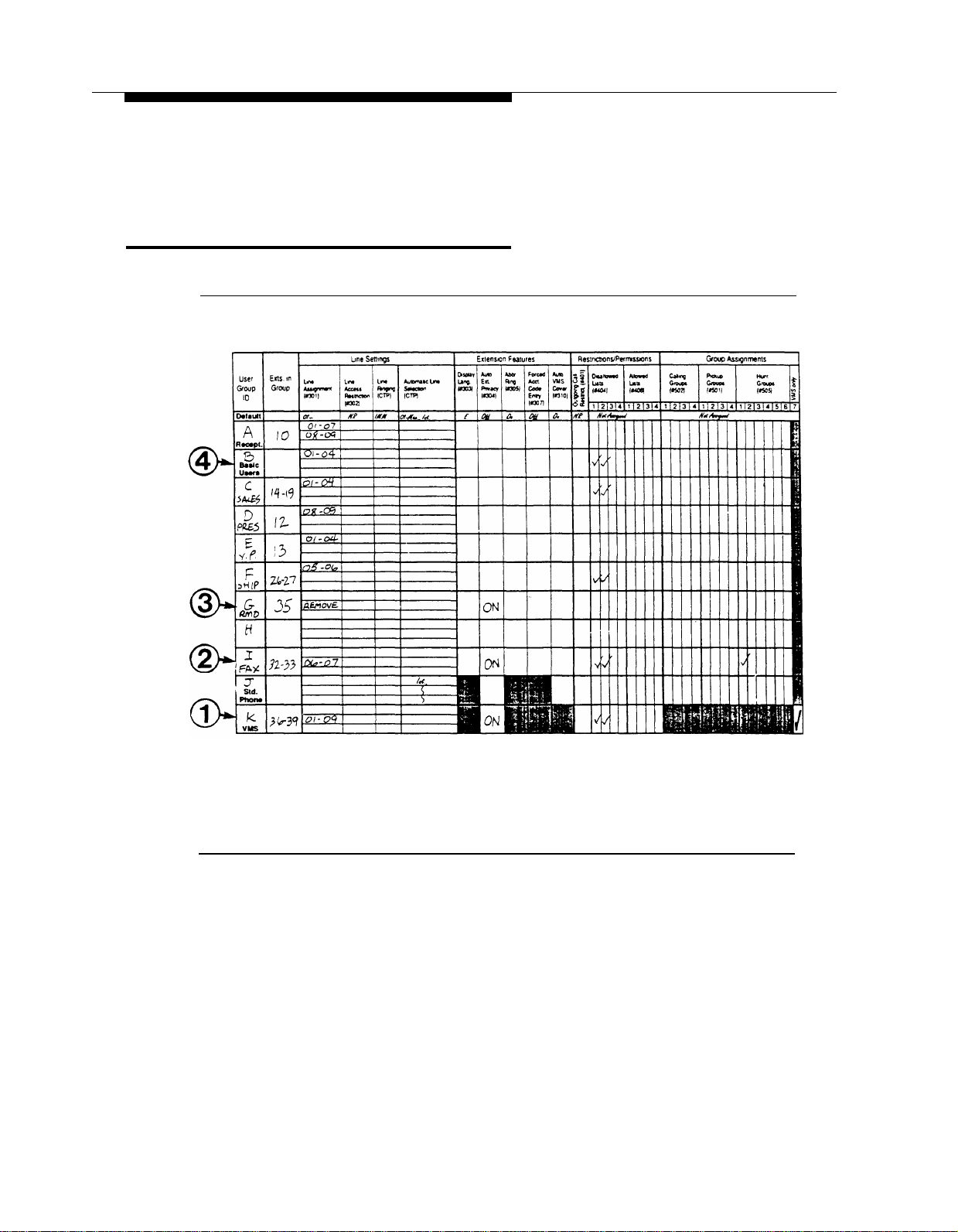
Form B2: Customized Extension Setting
Figure 2-3. PARTNER II Form B2: Customized Extension Settings
Use Form B2 (Figure 2-3) to identify groups of extensions which have the same
settings. A single extension may be included in its own user group if it has unique
settings. Whoever programs the PARTNER System can copy these settings from a
previously programmed extension using the Copy Settings programming option
(#399). The System Planner provides instructions for how to complete Form B2 for
the Receptionist (System Operator), other users and for fax extensions. Use the
procedure below to complete Form B2 for the PARTNER MAIL system extensions
and the Mail RMD.
2-6 Form B2: Customized Extension Setting

PARTNER System Planning
For the PARTNER MAIL system extensions:
■
Locate VMS in the “User Group ID” column and write K in that column.
■
Write the extension numbers for the PARTNER MAIL system
extensions in the “Exts. in Group” column.
■
This setting determines whether users may join calls on an extension.
—
—
■
Leave the remaining items blank if you intend to use the “Default”
settings listed at the bottom of the form.
■
Write an ID (K in this example) in the “User Group ID” column on Form
B1 for each PARTNER MAIL system extension (Figure 2-2).
For Delayed Call Handling: Write OFF in the “Auto Ext. Privacy”
column to make sure privacy is not assigned to the PARTNER
MAIL system extensions. This allows users to join a call after it
has been answered by the Automated Attendant service. The
system automatically disconnects from the call.
For Immediate Call Handling: Write ON in the “Auto Ext. Privacy”
column to make sure privacy is assigned to the PARTNER MAIL
system extensions. This prevents users from joining a call after it
has been answered by the Automated Attendant service.
The example in Figure 2-3 indicates that the default settings will apply to the
PARTNER MAIL system extensions except for the following:
■
Disallowed List number 1 is assigned to the PARTNER MAIL system
extensions. This means that the outcalling feature cannot be used to
place calls to the numbers listed in Disallowed List 1. (Refer to Chapter
1 in this guide for a description of the outcalling feature, and refer to
PARTNER II Release 3 Programming and Use for instructions on how
to program Disallowed Lists.
For Fax Call Handling:
Write FAX in the “User Group ID” column, and assign an ID (An
■
unused Alpha character from A to Z).
■
Write the fax extension number(s) into the “Exts. in Group” column.
Write the group ID (I in this example) into the “User Group ID” column
■
of Form B1 for each fax extension (Figure 2-2).
■
Write YES in the “Auto. Ext. Privacy” column. This setting ensures that
fax calls are not interrupted.
■
Make entries as appropriate for the remaining items, or leave the
remaining items blank if you intend to use the “Default” settings listed at
the bottom of the form.
If you intend to send and receive faxes, you may assign lines using the “Line
Assignment” column, and indicate “No Ring” in the “Line Ringing” column.
Form B2: Customized Extension Setting
2-7

PARTNER System Planning
For the RMD:
■
Write MAIL RMD in the “User Group” column and assign an ID.
■
Write the RMD extension number into the “Exts. in Group” column.
■
Write “Remove all lines” in the Line Assignment column.
■
Write YES in the “Auto. Ext. Privacy” column. This setting ensures that
maintenance calls are not interrupted.
■
Make entries as appropriate for the remaining items, or leave the
remaining items blank if you intend to use the “Default” settings listed at
the bottom of the form.
■
Write the group ID into the “User Group ID” column of Form B1 for the
RMD (Figure 2-2).
For other users:
■
Determine if Auto VMS Cover should be ON or OFF for the Basic User
extensions. Write ON, or OFF in the Auto. VMS Cover column.
■
Assign User Group IDs.
■
Write the group ID (B in this example) into the “User Group ID” column
of Form B1 for the users (Figure 2-2).
2-8 Form B2: Customized Extension Setting

PARTNER System Planning
Form C: Button Programming
Form C provides button templates for each type of MLS and MLC telephone. It is
recommended that you program a button on the telephone for the following
PARTNER MAIL system features:
Night Service button (Program on a system telephone at extension 10 only):
■
enables user to turn Night Service ON or OFF. When Night Service is ON,
and the PARTNER MAIL Automated Attendant handles calls always or at
night only, the system plays the Night Greeting and Night Menu.
The following buttons may be programmed onto any telephone.
■
VMS Cover button: enables users to turn VMS Coverage ON or OFF at their
extensions.
■
Voice Mailbox button: enables users to transfer callers directly to a PARTNER
MAIL system subscriber’s mailbox so that the caller can leave a message.
■
Auto Dial to the PARTNER MAIL system: enables users to press one button
to dial the PARTNER MAIL Hunt Group (777).
Form C: Button Programming
2-9

PARTNER System Planning
Night Service
Figure 2-4. PARTNER System Template for Night Service
Refer to section “8. System Settings” on PARTNER II Form A: System Configuration.
If “Night Service Button” is checked. Obtain the template for the system telephone
(MLS-34D, MLS-12D, or MLS-18D) at extension 10.
Select a button with lights and write “NightSVC” on the template area for the
selected button (Figure 2-4). When the feature button light is ON, the Night
Service feature is ON.
2-10 Form C: Button Programming
PARTNER System Planning
Any System Phone Features
The following feature buttons may be programmed on any user’s system telephone.
Obtain the template for the system telephone (MLS-6/MLC-6, MLS-12D/MLS-12,
MLS-18D) at the user’s extension.
Figure 2-5. PARTNER II R3 Form C for MLS6 and MLS18D
Form C: Button Programming
2-11

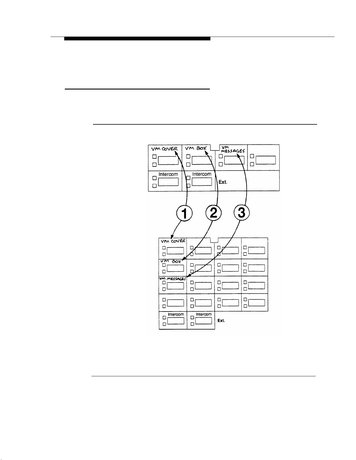
PARTNER System Planning
VMS Cover
Select a button with lights and write “VMCover” on the template area for the
button (Figure 2-5).
NOTE:
Turning VMS coverage ON and OFF at an extension does not affect CO Line
Coverage for outside calls ringing at that extension.
Voice Mailbox Transfer
Select a button to activate the Voice Mailbox Transfer feature and write
“VMBox” on the template area for the selected button.
Auto Dial into PARTNER MAIL System
Select a button that enables callers to automatically dial the PARTNER MAIL
system Hunt Group and write “VM Messages” on the template area for the
selected button.
2-12 Form C: Button Programming

PARTNER MAIL Planning
This chapter contains instructions for completing the PARTNER MAIL system
planning forms. You need information from the following PARTNER II Release 3
forms:
■
Form A: System Configuration
■
Form B1: System Extensions
■
Form B2: Customized Extension Settings
3
You can find blank PARTNER MAIL system planning forms in Appendix A. Make
copies of the forms for planning and leave the originals in this manual. Store the
completed forms in the back cover of PARTNER MAIL™ Installation and Use.
The PARTNER MAIL system forms you need are listed below:
■
Form 1: Mailbox Assignments
■
Form 2: System Parameters
■
Form 3: Voice Mail Greeting
■
Form 4: Automated Attendant Settings
■
Form 5: Automated Attendant Day Greeting and Menu
■
Form 6: Automated Attendant Night Greeting and Menu
■
Form 7: Automated Attendant Submenus
■
Form 8: Automated Attendant Announcements
■
Form 9: Group Lists
■
Form 10: Line Ownership
3-1

PARTNER MAIL Planning
Form 1: Mailbox Assignments
Figure 3-1. PARTNER MAIL Form 1
The PARTNER MAIL system is shipped with mailboxes created for extensions 10
through 57. Use Form 1 (Figure 3-1) to record the name of each PARTNER MAIL
system subscriber assigned to each extension at your office. Form 1 makes it easier
to record subscriber names for the PARTNER MAIL system directory, should you
decide to use one, and also makes it easier to keep track of subscribers if you must
modify or delete mailbox assignments.
You can also use Form 1 to designate Guest Mailboxes for users who do not have
their own extensions, but still require a mailbox. Assign a COS of 7, 8, or 9 to an
unused extension from 10 through 57. Assign the first Guest Mailbox to the highest
numbered extension available (e.g., extension 57) and work backwards toward
extension 10 to assign additional Guest Mailboxes. The PARTNER MAIL system
does not attempt to transfer callers receiving Automated Attendant Service to the
extension associated with the Guest Mailbox. Instead, it transfers callers directly to
the Guest Mailbox where they can leave a message. Guests may log on and retrieve
messages from any touch-tone phone.
3-2 Form 1: Mailbox Assignments

PARTNER MAIL Planning
To use the PARTNER MAIL system’s Voice Mailbox Transfer features, assign a two
digit mailbox number from 10 through 57 for each mailbox. If you assign a mailbox
greater than 57, you must administer a “Transfer Not Permitted” COS of 7, 8, or 9
for that mailbox. The system routes callers receiving the Automated Attendant
Service to the mailbox (greater than 57), not to the extension associated with the
mailbox. The System Administrator programs mailboxes using the Mailboxes menu.
Refer to Chapter 6 in PARTNER MAIL™ Installation and Use for details on how to
change, add, or delete mailboxes. Complete items 1 through 4 as instructed below.
Mailbox
Enter extension numbers for each subscriber (maximum of 48 for extensions
10 through 57). The extension number corresponds to the mailbox number.
Make additional copies of Form 1 as required.
Name
Refer to PARTNER II Release 3 Form B1 and write the name of each
subscriber next to the appropriate mailbox number. Since you can organize
your directory (if you plan to use one) by first or last name, consider entering
the names in a manner that highlights the name you plan to record. For
example, if you plan to record only the first name, write the first name in all
capital letters and the last name in inital capital letters: BOB Smith. If you plan
to record only the last name, write SMITH, Bob.
COS (Class of Service)
The Class of Service describes the characteristics of the mailbox. The factorysetting COS for each mailbox is 2. This COS should satisfy the majority of
subscribers. Review the Class of Service table and the guidelines which
follow. To modify the COS for an extension, choose a number from the Class
column, and write that number into the COS column for the appropriate
extension. Make no entry if you are not modifying the COS for a mailbox.
COS Key
Class
1 5 Permitted
2
✔
3
4
5
6
7 15
8
Mins.
10
15
5 Permitted Permitted
10
15
15
Transfer
Permitted
Permitted
Permitted Permitted
Permitted
Not Permitted Not Permitted
Not Permitted
Outcalling
Not Permitted
Not Permitted
Not Permitted
Permitted
Permitted
9
60
Not Permitted
Not Permitted
Form 1: Mailbox Assignments
3-3

PARTNER MAIL Planning
Use the following guidelines to select the Class of Service:
■
Mins. (Minutes) (10 ✔ ) — the size of the mailbox. Each mailbox can
have 5, 10, 15, or 60 minutes of storage available. Use the 60-minute
size only for mailboxes used to record orders, lengthy messages, or as
a Dictaphone™. The total storage time for all mailboxes is four hours.
The sum of messages stored in each mailbox may exceed four hours.
■
Transfer Type — determines how the PARTNER MAIL system
processes a call when a caller indicates this mailbox as a transfer
destination.
—
—
■
Outcalling (Not Permitted ✔ ) — if outcalling is permitted, and the
subscriber administered it using the Voice Mail Service, the system
calls the subscriber at a designated telephone or beeper number
whenever a new message is in the subscriber’s mailbox. Use discretion
when permitting use of the outcalling feature. Unless a Disallowed List
has been programmed into the PARTNER Communications System,
the system does not restrict the destination of the outside call. Refer to
PARTNER
Use for instructions on how to program disallowed lists.
Transfer Permitted ✔ : the system attempts to transfer the call to
the extension entered by the caller.
Transfer Not Permitted: the system does not attempt to transfer
the call to the extension entered by the caller. Instead, the
system transfers the caller directly to the extension’s voice
mailbox. Assign a COS of 7, 8, or 9 (Transfer Not Permitted) to
mailboxes that provide a place for callers to leave messages for
people who do not have dedicated extensions, such as visitors,
guests, or employees who do not have their own phones. When
a caller dials an extension with a COS of 7, 8, or 9, the system
immediately prompts that caller to leave a message.
®
II Communications System Release 3 Programming and
Letter Key
The directory feature enables callers to reach an extension by dialing a
subscriber’s first or last name, use the the Letter Key to translate up to
four letters of the first or last name of the person to whom the mailbox
is assigned. Each letter of the name has a two-digit code (see the
Letter Key on the next page). The first digit represents the number on
the dialpad where the letter appears. The second digit represents
whether the letter appears in the first, second, third, or fourth position
on the button. For example, the first four characters of the name
“Henderson” translate as shown below:
3-4 Form 1: Mailbox Assignments

PARTNER MAIL Planning
H
4
The “H” is on the “4” button in the second position, “E” is on the “3”
button in the second position, and so on.
Write the first four characters of a subscriber’s first or last name into
the upper block on the letter key, then use the Letter Key as a
reference to write the correct translation digits into the blocks
immediately below each character. The implementor uses the Letter
Key to program the directory list. The PARTNER MAIL system creates
the directory as mailboxes are created for each subscriber. If the
Automated Attendant Main Menu informs callers how to access the
directory service, be sure to indicate which name (first or last) is used
in the directory.
Letter Key
A = 21
B = 22
C = 23 P = 71
2
N = 62
O = 63
E
3
2
N
6 2
D
3
1
D = 31
E = 32
F = 33
G = 41 T = 81
H = 42
I = 43
J = 51 W = 91
K = 52
L = 53
M = 61
Q = 72
R = 73
S = 74
U = 82
V = 83
X = 92
Y = 93
Z = 94
Form 1: Mailbox Assignments
3-5

PARTNER MAIL Planning
Form 2: System Parameters
Position
Fax Extension or Fax
Hunt Group Extension
System Administrator
General Mailbox Owner 10 ✔
System Operator 10 ✔
Fax Message Receiver
Name
Mailbox
EXT.
Factory
Setting
Figure 3-2. PARTNER MAIL Form 2
Complete Form 2 (Figure 3-2) to define the parameters of your PARTNER MAIL
system. The System Administrator programs System Parameters from the PARTNER
MAIL System Parameters menu. Refer to Chapter 6 in PARTNER MAIL™ Installation
and Use for details on how to change, add, or delete each of the parameters
described below.
3-6 Form 2: System Parameters

PARTNER MAIL Planning
NOTE:
You can only use Fax Call Handling with Immediate Call Handling.
Voice Mail Positions
Use PARTNER II Release 3 Form B1 to identify the names and extensions for
subscribers you are assigning as the System Administrator, the General
Mailbox Owner, the System Operator and the Fax Message Receiver. Refer to
Chapter 1 of this guide for a description of responsibilities.
■
Fax Extension
— Refer to PARTNER II Release 3 Form B1 to identify the
extension jack number (on the PARTNER System’s 206 module)
that connects to the Fax machine.
— If there is more than one fax machine, refer to PARTNER II
Release 3 form B2 to determine the Fax Hunt Group extension
(771 to 776).
— Write the fax extension or Hunt Group number into the space
provided.
■
System Administrator
Enter the name and extension of the person responsible for PARTNER
MAIL system administration.
■
General Mailbox Owner
Enter the name and extension of the person responsible for maintaining
the General Mailbox (stores messages not directed to a specific voice
mailbox). The default is extension 10.
■
System Operator Extension
Enter the name and extension of the receptionist or person primarily
responsible for answering telephones at your office. The default is
extension 10.
■
Fax Message Receiver
Enter the name and the extension of the subscriber who you want
notified via the Message light when a fax transmission has been
received at a fax extension. Do not assign this responsibility to a
person using a single line telephone.
Form 2: System Parameters
3-7
PARTNER MAIL Planning
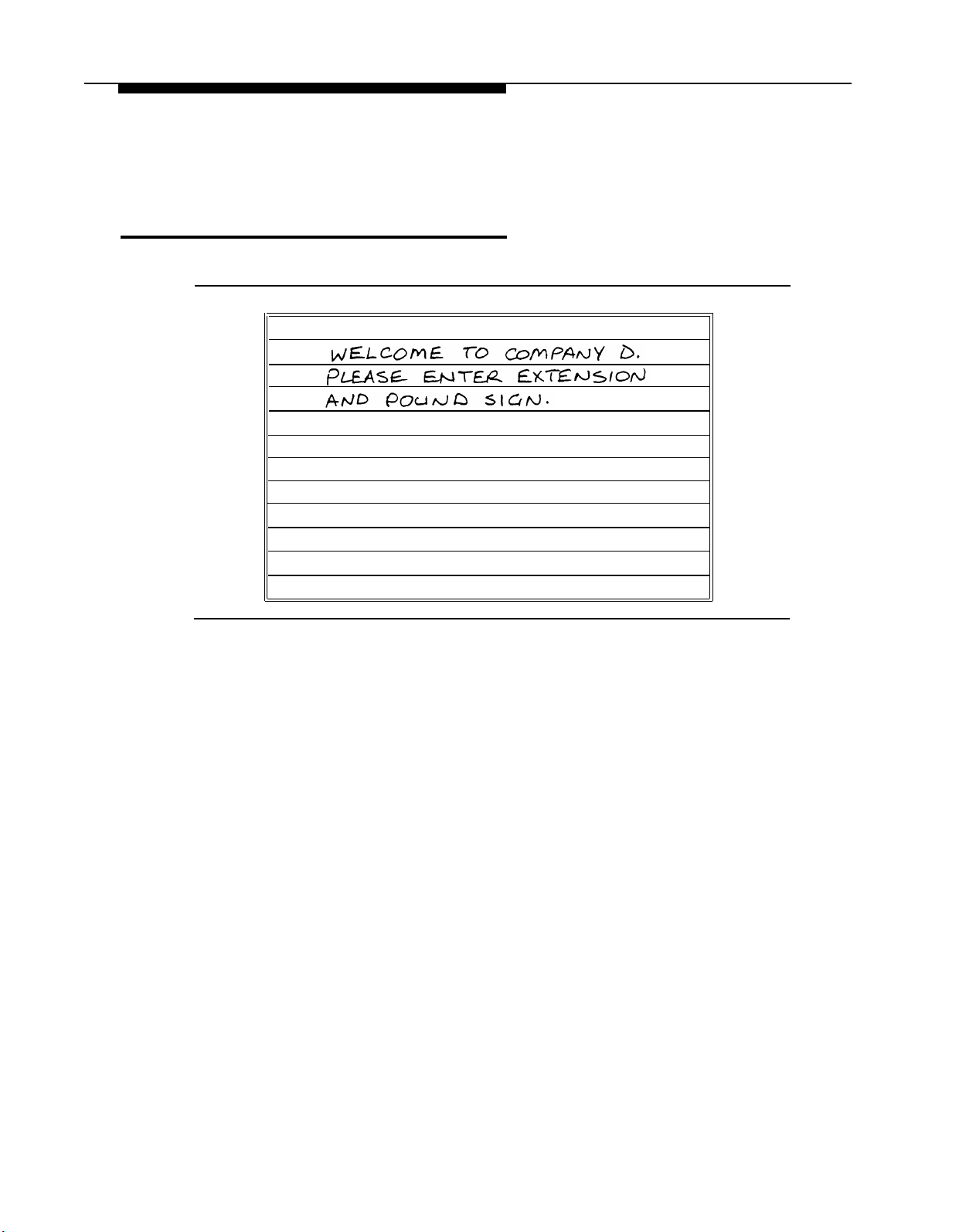
Form 3: Voice Mail Greeting
Voice Mail Greeting
Figure 3-3. PARTNER MAIL Form 3
When subscribers dial into PARTNER MAIL Voice Mail Service they hear the
following factory-set greeting:
Welcome to PARTNER MAIL. Please enter extension and pound sign.
It is recommended that you use the factory-set greeting. If, however, your company
prefers a customized greeting, use Form 3 (Figure 3-3), and the instructions which
follow, to write a script. To record your Voice Mail Greeting, follow the instructions
found in Chapter 6 of PARTNER MAIL™ Installation and Use.
■
Write the greeting that plays to voice mail subscribers.
■
Your greeting can be up to two minutes long.
■
The greeting must include instructions to enter the subscriber's extension and
the pound sign.
3-8 Form 3: Voice Mail Greeting

PARTNER MAIL Planning
Form 4: Automated Attendant Settings
Touch-Tone Gate
■
The Touch-Tone Gate is automatically set to ON if the system is used for Fax
Call Handling.
■
Check one:
✓
❑
ON
OFF ✔
❑
■
To administer: Press
and PASSWORD [#] . Press [9] [3] [5] .
Extensions in Enter Plan
[
Intercom
]
[7] [7] [7] Enter administrator's
EXTENSION
[#]
■
Check the first digit of each extension used in the dial plan.
1 ❑
✓
2 ❑
✓
3 ❑✓4 ❏
5 ❏
7 ❑
✓
Figure 3-4. PARTNER MAIL Form 4
Complete Form 4 (Figure 3-4) to record the system-wide settings that you must keep
in mind when planning the PARTNER MAIL Automated Attendant greetings and
menus.
Complete Form 4 only if you plan to use PARTNER MAIL Automated Attendant
service.
Touch-Tone Gate
Read the following guidelines before checking the ON or OFF box to indicate
your Touch-Tone Gate setting.
■
If you do not have a fax extension, read the following to decide whether
to set the gate ON or OFF.
■
The Touch-Tone Gate factory-setting is OFF.
■
If you have a Fax Machine Extension (see Form 2), the Touch-Tone
Gate is automatically set to ON and cannot be turned OFF.
Form 4: Automated Attendant Settings
3-9

PARTNER MAIL Planning
—
—
Extensions in Dial Plan
Check the first digit of each extension, Hunt Group extension, or Calling
Group. used in the dial plan. If, for example, you use extensions 10
through 30, you would check 1, 2 and 3. If you plan to program
extension Hunt Groups or Calling Groups, check box 7 since Hunt
Groups are reached by dialing 771 — 776 and Calling Groups are
reached by dialing 71 — 74. You will use the dial plan when planning
the Automated Attendant Menus on Forms 5 and 6.
When the Touch-Tone Gate is ON, the Automated Attendant Day
or Night greeting prompts the caller to press [1]
calling from a touch-tone phone. If the system does not detect a
touch-tone, it assumes that the caller is using a rotary phone and
handles the call based upon the Dial 0 / Timeout Options set by
the System Administrator. This enables rotary callers to quickly
bypass the Automated Attendant menu, and reach a receptionist
or system user who handles their call.
If the Touch-Tone gate is OFF, rotary callers are not transferred
until the Automated Attendant menu plays. However, if most
callers to your company have touch-tone phones, leave the
Touch-Tone Gate set to OFF to eliminate a step in reaching the
desired destination.
if he or she is
3-10 Form 4: Automated Attendant Settings

PARTNER MAIL Planning
Form 5: Day Greeting and Menu
Form 5 consists of three pages:
■
Page 1: the Day Greeting Script,
■
Page 2: the Day Main Menu Definition form, and
■
Page 3: the Day Main Menu Script
Day Greeting Script
Day Greeting Script
Figure 3-5. PARTNER MAIL Form 5 Page 1: Day Greeting
Use Page 1 of Form 5 (Figure 3-5) to write the script for the greeting that plays when
callers reach the Automated Attendant Service during business hours. Ten seconds
are allocated for the greeting. If the Touch-Tone Gate is ON (see Form 4) you must
instruct the caller to Press 1 now if you are calling from a touch-tone
phone.
Form 5: Day Greeting and Menu 3-11
PARTNER MAIL Planning
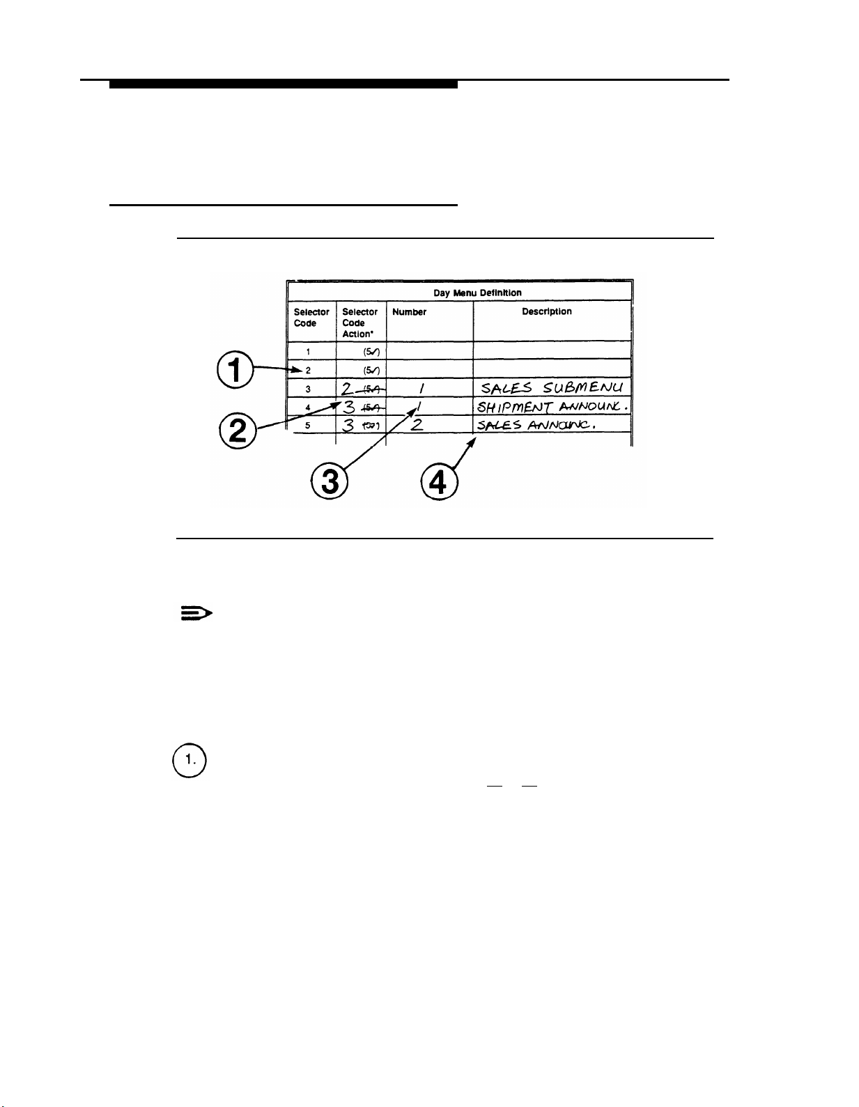
Day Main Menu Definition
Figure 3-6. PARTNER MAIL Form 5 Page 2: Day Menu Definition
NOTE:
If you plan to use submenus or a prerecorded announcement as options on
your Main Menu, you must create them before you can complete the Day
Main Menu programming. See Form 7 for setting up submenus and Form 8
for setting up announcements.
Write the following information on the Day Main Menu Definition form (Figure 3-6):
Selector Code
Callers press a Selector Code (a key from [1]
an item from the Main Menu. Each Selector Code has a corresponding
Selector Code Action that causes the system to transfer callers to the
department or individual that they want to speak to, or to the announcement
or submenu that they want to hear. Assign the most requested department or
extension as the first route and list the Selector Codes in ascending order so
that it’s easier for callers to remember them. For the same reason, try to limit
the menu to five or fewer selections.
to [9] on the dialpad) to select
3-12 Form 5: Day Greeting and Menu

PARTNER MAIL Planning
Selector Code Action 5 (Direct Extension Transfer, see description below) is
the factory-setting for Selector Codes 1 through 5. This enables callers to dial
an extension directly from the main menu. Use step 2 of this procedure to
change these settings.
Selector Code Action
The Selector Code Action determines the action the system takes after a
caller presses a Selector Code. Write the appropriate Selector Code Action
from the list below:
■
Action 1 — Selector Code Transfer
When a caller presses the Selector Code, the system transfers the call
to the specific extension, Hunt Group, or Calling Group that you assign.
■
Action 2 — Play an Existing Submenu
When a caller presses the Selector Code, the system plays another
menu from which the caller presses another Selector Code. Be sure to
complete Form 7: Automated Attendant Submenus. The submenu must
already exist before you can program this action.
■
Action 3 — Play an Existing Announcement
When a caller presses the Selector Code, the system plays a
prerecorded announcement. Use this Action to provide information such
as your business hours or a mailing address. Be sure to complete Form
8: Automated Attendant Announcements. The announcement must
already exist before you can program this action.
■
Action 4 — Prompted Transfer
When callers press a Selector Code, the system prompts them to enter
an extension. For example: ANY Travel uses extensions 10 through 40
in their dial plan (see Form 4). They use Selector Codes 1 through 4 to
direct callers to submenus and announcements. To enable callers to
dial extensions from the main menu, ANY travel assigns Prompted
Transfer to Selector Code 5. Callers to ANY Travel press [5]
at the
main menu then dial an extension number.
■
Action 5 ✔ — Direct Extension Transfer
Callers can dial an extension directly from the Day Main Menu. Write 5
(the default) next to the Selector Code(s) that match the first digit(s) of
the dial plan (Form 4). For example, if extensions 1 and 2 are checked
on Form 4 (indicating that all of your extensions begin with 1 or 2)
leave Selector Codes 1 and 2 at the factory-setting of 5.
Number
For Selector Code Actions 1, 2, or 3, write the corresponding extension, Hunt
Group, or Calling Group number, submenu number, or announcement number
associated with the Action. Actions 4 and 5 do not require an entry in the
Number column.
Description
Write the name of the extension, Hunt Group, Calling Group, submenu, or
announcement, that describes the Selector Code Action.
Form 5: Day Greeting and Menu
3-13

PARTNER MAIL Planning
Day Main Menu Script
Check One:
✓
❏
❏
❏
System Operator ✔
General Mailbox
Disconnect
Day Menu Script
Figure 3-7. PARTNER MAIL Form 5 Page 3: Day Menu Script
Day Dial 0/Timeout Action Options
Review the three options described below to choose how the system handles calls
when callers press [0]
seconds after being prompted. Select one of the following by marking a check in the
appropriate box on Form 5 (Figure 3-7):
■
System Operator ✔ — Transfer caller to the System Operator for assistance
■
General Mailbox — Transfer caller to the General Mailbox to leave a
message.
Disconnect — Disconnect the call.
■
3-14 Form 5: Day Greeting and Menu
, or do not enter a Selector Code or extension, within four

PARTNER MAIL Planning
Use page 3 of Form 5 (Figure 3-7) to write a script that presents the menu choices
to the caller. Your script could prompt callers to:
■
Enter the extension if Selector Code Action 5 (direct extension transfer) is
specified for some Selector Codes.
If you know the extension that you wish to reach, dial it now.
■
Access the directory.
If you know the last name of the person you want to speak to, press [*]
[2]
If you offer a caller the directory list, tell them whether it is listed by first or last
name.
■
Press a Selector Code to:
— Transfer to an extension, Hunt Group or Calling Group,
— Access a submenu,
to access the directory.
— Hear an announcement
■
Press [*]
■
Tell callers what happens if they do nothing. This is the Dial 0 / Timeout
[4] to replay the menu.
Option that you indicated during the previous step.
If you need assistance, stay on the line and an operator will
assist you.
If applicable, the script should explain to callers how they can reach an individual
extension, how to send a fax, and how to hear an announcement, or access a
submenu.
NOTE:
PARTNER MAIL subscribers calling from outside on a line answered by the
Automated Attendant service can enter [*]
[7] to receive Voice Mail Service
and retrieve their messages.
Form 5: Day Greeting and Menu
3-15

PARTNER MAIL Planning
Form 6: Night Greeting and Menu
Form 6 consists of three pages:
■
Page 1: the Night Greeting Script,
■
Page 2: the Night Main Menu Definition form, and
■
Page 3: the Night Main Menu Script
Night Greeting Script
Night Greeting Script
Figure 3-8. PARTNER MAIL Form 6 Page 1: Night Greeting Script
Use Page 1 of Form 6 (Figure 3-8) to write the script for the greeting that plays when
callers reach the Automated Attendant Service when Night Service is ON. Ten
seconds are allocated for the greeting. If the Touch-Tone Gate is ON (see Form 4)
instruct the caller to . . . press 1 now if you are calling from a touch-
tone phone.
3-16 Form 6: Night Greeting and Menu

PARTNER MAIL Planning
Night Menu Definition Form
Complete page 2 of Form 6 (Figure 3-9) to design the night menu. These are the
menu selections that the caller hears if Automated Attendant coverage is chosen for
hours when Night Service is ON. Use this form even if the Night Menu and the Day
Menu are identical.
NOTE:
If you plan to use submenus or a prerecorded announcement as options on
your Night Menu, you must create them before you can complete the Night
Menu programming. See Form 7 for setting up submenus and Form 8 for
setting up announcements.
Figure 3-9. PARTNER MAIL Form 6 Page 2: Night Menu Definition
Write the following information on the Night Main Menu Definition form (Figure 3-6).
Refer to “Day Menu Definition Form” earlier in this Chapter for a description of each
field.
Selector Code
Form 6: Night Greeting and Menu
3-17

PARTNER MAIL Planning
Selector Code Action
Write in the appropriate Selector Code Action from the list below.
■
Action 1 — Selector Code Transfer
■
Action 2 — Play an Existing Submenu
■
Action 3 — Play an Existing Announcement
■
Action 4 — Prompted Transfer
■
Action 5 ✔ — Direct Extension Transfer
Number
For Selector Code Actions 1, 2, or 3, write the corresponding extension, Hunt
Group, or Calling Group number, submenu number, or announcement number
associated with the Action. Actions 4 and 5 do not require an entry in the
Number column.
Description
Write the name of the extension, Hunt Group, Calling Group, submenu, or
announcement, that describes the Selector Code Action.
Night Main Menu Script
Check One:
System Operator
❏
✓
General Mailbox ✔
❏
Disconnect
❏
Night Menu Script
Figure 3-10. PARTNER MAIL Form 6 Page 3: Night Menu Script
3-18 Form 6: Night Greeting and Menu

PARTNER MAIL Planning
Night Dial 0/Timeout Action Options
Review the options described below to choose how the system handles calls when
callers press 0, or do not enter a Selector Code or extension, within four seconds
after being prompted. Select one of the following by marking a check in the
appropriate box on page 2 of Form 6 (Figure 3-10):
■
System Operator — Transfer caller to the System Operator for assistance
■
General Mailbox ✔ — Transfer caller to the General Mailbox to leave a
message.
■
Disconnect — Disconnect the call.
Use page 3 of Form 6 (Figure 3-10) to write a script that presents the night menu
choices to the caller. Tell the caller to:
■
Dial the extension.
If you know the extension that you wish to reach, dial it now.
■ Access the directory.
If you know the last name of the person you want to speak to, press [*]
[2]
to access the directory.
If you offer a caller the directory list, tell them whether it is listed by first or last
name.
Press a Selector Code to:
■
— Transfer to an extension, Hunt Group or Calling Group,
— Access a submenu,
— Hear an announcement
■
Press [*]
■
Tell the caller what happens if he or she does nothing. This is the Dial 0 /
[4] to replay the menu.
Timeout Option that you specified during the previous step.
If you’d like to leave a message, please hold. Your call will be
returned during business hours.
Form 6: Night Greeting and Menu 3-19

PARTNER MAIL Planning
Form 7: Submenus
If you specified a Selector Code Action of 2 — Play an existing submenu — on Form
5 (Day Greeting and Menu Definition) or Form 6 (Night Greeting and Menu
Definition) use Form 7 (Figure 3-11) to define and write a script for the submenu.
You can create up to 99 submenus, but keep in mind that more than two levels of
submenus can confuse callers. You must create and record each submenu (last
level first) before you record the Automated Attendant Day or Night Menu that refers
to the submenu.
Make additional copies of this form as required.
Form 7 consists of the following two pages:
■
Page 1: the Submenu Definition Form,
■
Page 2: the Submenu Script
3-20 Form 7: Submenus

PARTNER MAIL Planning
Submenu Definition Form
Figure 3-11. PARTNER MAIL Form 7 Page 1: Submenu Definition
Write the Submenu Number (01 through 99) in the heading of the Submenu
Definition form (Figure 3-11). You will need this number when you specify
Action 2 on a Day or Night Menu, or a Submenu Definition form. Also, the
system prompts the System Administrator to enter this number when he or
she creates a submenu.
Write the following information on the Submenu Definition Form (Figure 3-11).
Refer to “Day Menu Definition Form” earlier in this Chapter for a description of
each field.
Selector Code
Selector Code Action
Write in the appropriate Selector Code Action from the list below.
■
Action 1 — Selector Code Transfer
■
Action 2 — Play an Existing Submenu
■
Action 3 — Play an Existing Announcement
■
Action 4 — Prompted Transfer
■
Action 5 — Direct Extension Transfer
Form 7: Submenus
3-21

PARTNER MAIL Planning
Number
For Selector Code Actions 1, 2, or 3, write the corresponding extension, Hunt
Group, or Calling Group number, submenu number, or announcement number
associated with the Action. Actions 4 and 5 do not require an entry in the
Number column.
Description
Write the name of the extension, Hunt Group, Calling Group, submenu, or
announcement, that describes the Selector Code Action.
Submenu Script
Submenu No. _______ Script
Figure 3-12. PARTNER MAIL Form 7 Page 2: Submenu Script
Use page 2 of Form 7 (Figure 3-12) to write a script that presents the submenu
choices to the caller. Tell the caller to:
■
Press [*] [4] to replay the menu.
■
Press [*]
■
Press [*]
■
Enter a selector code to hear an announcement, hear another submenu, or
transfer to an extension, Calling Group, or Hunt Group.
For the cruise travel agent, press 3 now.
3-22 Form 7: Submenus
[#] to go back to the previous menu.
[7] to go back to the first menu.

PARTNER MAIL Planning
Form 8: Announcements
Complete Form 8 to create announcements providing current or frequently requested
information. You can create up to 99 announcements. Since you can also create up
to 99 submenus, you could enable callers to access many different announcements.
Remember, however, that more than two levels of submenus confuse callers. Update
the announcements regularly to provide the latest information, such as weather
reports, interest rates, product information, directions, and entertainment listings.
Each announcement can be up to two minutes long.
Make additional copies as required.
Form 8: Announcements
3-23

PARTNER MAIL Planning
Figure 3-13. PARTNER MAIL Form 8: Automated Attendant Announcements
Complete the following information on Form 8 (Figure 3-13):
Announcement No.
Assign each announcement an identifying number (1 through 99). You will
need this number when you specify Action 3 on a menu or submenu Definition
form. Also, the system prompts the System Administrator to enter this number
when he or she creates an announcement. If you want to record more than
one announcement, make additional copies of the blank planning form. Note
that an announcement must be created and recorded before you can program
a Selector Code to refer to it.
Script
Write the announcement script in the space provided.
If a caller does not respond to the announcement within four seconds, the
system disconnects. Therefore, be sure to tell the caller near the end of the
announcement to perform the following if you do not want the caller to be
disconnected:
■
press [0] to transfer to the System Operator,
■
press [*] [4] to go back to the previous submenu,
■
press [*] [8] to transfer to an extension.
3-24 Form 8: Announcements

PARTNER MAIL Planning
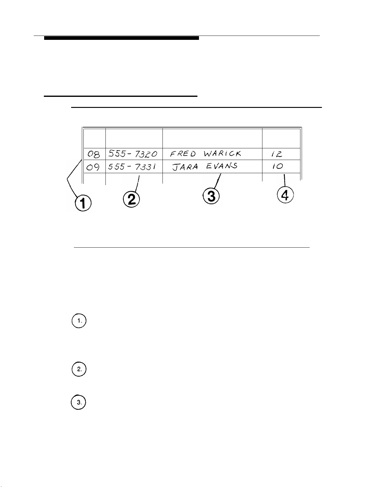
Form 9: Group Lists
Figure 3-14. PARTNER MAIL Form 9: Group Lists
Use Form 9 to organize Group Lists for your office. You can create up to 99
Group Lists which provide the ability to send voice mail messages to multiple
subscribers without entering each extension. A subscriber can enter [*]
followed by a Group List Number, rather than an extension, to send the
message to all mailboxes on the Group List. Create Group Lists to suit
business needs. Provide a copy of the list to each subscriber who is a
member of the group.
Fill in the following information on Form 9 (Figure 3-14):
Group List No.
Write the number of the Group List. This is the number subscribers use to
address their Group List messages. If you want more than one Group List,
number the lists sequentially.
Group Name
Write the Name of the group to which the members of the list belong.
Extension
Write the extensions to be included on the Group List. Your business needs
determine which subscribers to include in a Group List.
Name
Write the name of the subscriber assigned to each extension.
[5]
Form 9: Group Lists
3-25
PARTNER MAIL Planning
Form 10: Line Ownership
Line
Telephone
Number
Line Owner Owner's
Extension
Figure 3-15. PARTNER MAIL Form 10: Line Ownership
Use Form 10 (Figure 3-15) to identify the CO (outside) lines at your site covered by
VMS Line Cover, and dedicated to a specific person or project. Specify the extension
and the subscriber who “owns” the CO line. When a call coming in on this line is not
answered manually, the system associates the CO line number with an extension
and plays the extension’s personal greeeting. This enables the caller to leave a
message in the called party’s voice mailbox. Use the following instructions to
complete Form 10 (Figure 3-15):
CO Line
■
Refer to PARTNER II Release 3 Form A to identify the two digit CO
Line number of each line that has “VMS MAIL” in the Line Coverage
column.
■
Write the CO Line number in the space provided.
Telephone Number
■
Locate the Telephone number on PARTNER II Form A.
■
Write that number in the space provided.
Line Owner
■
Locate the Line Owner on PARTNER II Form A.
■
Write the name of the Line Owner in the space provided.
3-26 Form 10: Line Ownership

PARTNER MAIL Planning
Owner's Ext.
■ Locate the owner’s extension on PARTNER II Form B1.
■ Write the extension number in the space provided.
Form 10: Line Ownership
3-27

Appendices

PARTNER MAIL Forms

Form 1: Mailbox Assignments
■
Write each subscriber’s extension, name, and COS (see the COS Key on the
following page).
Translate the first four letters of the subscriber’s first or last name using the
■
“Letter Key” shown on the following page.
■
To administer: Press
and
PASSWORD
[
Intercom
[#]
.
Press [9] [4] .
]
[7] [7] [7] . Enter administrator's
EXTENSION
[#]
Mailbox
Name
COS
Letter Key

Class of Service (COS) Key
Class
1 5
2 ✔
3 15
4 5 Permitted Permitted
5
6
7
8
9 60
Letter Key
A = 21 N = 62
B = 22 O = 63
C = 23 P = 71
Mins.
10
10
15
15 Not Permitted
15
Transfer
Type
Permitted
Permitted
Permitted
Permitted
Permitted
Not Permitted
Not Permitted Not Permitted
Outcalling
Not Permitted
Not Permitted
Not Permitted
Permitted
Permitted
Not Permitted
Permitted
D = 31 Q = 72
E = 32 R = 73
F = 33 S = 74
G = 41 T = 81
H = 42 U = 82
I = 43 V = 83
J = 51 W = 91
K = 52 X = 92
L = 53 Y = 93
M = 61 Z = 94

Form 2: System Parameters
Voice Mail Positions
■
The fax extension or fax Hunt Group extension.
■
The System Operator and the General Mailbox Owner are usually the same
person.
■
The factory settings are marked with a check ( ✔ ).
■
To administer system parameters: Press
administrator’s EXTENSION [#]
Position
Fax Extension or Fax
Hunt Group Extension
System Administrator
General Mailbox Owner
System Operator
Fax Message Receiver
[ Intercom ] [7] [7] [7] . Enter
and PASSWORD [#] . Press [9] [1] .
Name
Mailbox
EXT.
Factory
Setting
9997
✔
10
✔
10
✔

Form 3: Voice Mail Greeting
■
The factory-setting is:
Welcome to PARTNER MAIL. Please enter extension and pound sign.
If changing the greeting, remind callers to enter the subscriber’s extension and
■
the pound sign.
■
Greeting cannot exceed two minutes
■
To administer: Press
and
PASSWORD
[
Intercom
[#] . Press [9] [7] [1] .
]
[7] [7] [7] . Enter administrator's
Voice Mail Greeting
EXTENSION
[#]

Form 4: Automated Attendant Settings
Touch-Tone Gate
■
The Touch-Tone Gate is automatically set to ON if the system is used for Fax
Call Handling.
■
Check one:
ON
❏
OFF ✔
❏
■
To administer: Press
and
PASSWORD
Extensions in Enter Plan
■
Check the first digit of each extension used in the dial plan.
[
Intercom
]
[7] [7] [7] . Enter administrator's
[#] . Press [9] [3] [5] .
EXTENSION
[#]
❏ 2 ❏
1
3 ❏
4 ❏
5 ❏
7 ❏

Form 5: Day Greeting and Menu
■
Greeting cannot exceed ten seconds.
■
If the Touch-Tone Gate is ON (see Form 4) inform callers using touch-tone
phones to press 1.
■
To administer: Press
and
PASSWORD
[
Intercom
[#] . Press [9] [7] [3] [1] .
Day Greeting Script
]
[7] [7] [7] . Enter administrator's
EXTENSION
[#]

Form 5 (2 of 3): Day Menu Definition Form
■
If using Automated Attendant for Day and Night coverage, complete both the
Day and the Night Menu Definition forms even if the menus are identical.
■
No entries are required in the Number and Description columns if using
Selector Code Actions 4 or 5.
■
Fill in the Number and Description columns if using Selector Code Actions 1,
2, or 3.
■
To administer: Press [ Intercom ] [7] [7] [7] ; EXTENSION [#] PASSWORD [#] [9]
[3] [1] .
Day Menu Definition
Selector
Code
Selector
Code
Action*
1
2
3
4
5
6
7
8
9
*Selector Code Action Key
1
Selector Code Transfer
(5 ✔ )
(5 ✔ )
(5 ✔ )
(5 ✔ )
(5 ✔ )
Number
Description
2
Play an existing submenu
3
Play an existing announcement
4
Prompted transfer
5
Direct extension transfer ✔

Form 5 (3 of 3): Day Menu Script
Day Dial 0 / Timeout Options
■
Specify where calls should be transferred if the caller does not enter a
Selector Code or if they press [0]
Check One:
❏
System Operator ✔
❏
General Mailbox
❏
Disconnect
Script for Day Menu Prompts
■
Write a script that contains the menu which callers will hear after the
Automated Attendant Day Greeting (Form 5 page 1).
■
The menu cannot exceed two minutes.
.
Day Menu Script
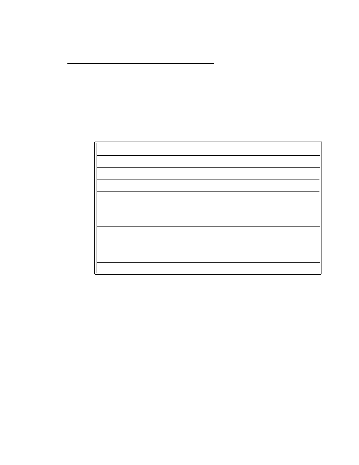
Form 6: Night Greeting and Menu
Greeting cannot exceed ten seconds.
■
If the Touch-Tone Gate is ON (see Form 4) inform callers using touch-tone
■
phones to press 1.
■
To administer: Press
[7] [3] [2] .
[
Intercom
]
[7] [7] [7] ;
Night Greeting Script
EXTENSION
[#]
PASSWORD
[#] [9]

Form 6 (2 of 3): Night Menu Definition Form
■
If using Automated Attendant for Day and Night coverage, complete both the
Day and the Night Menu Definition forms even if the menus are identical.
■
No additional entries are required if using Selector Code Actions 4 or 5.
■
To administer: Press
[3] [2] .
[
Intercom
]
[7] [7] [7] ;
EXTENSION
Night Menu Definition
[#]
PASSWORD
[#] [9]
Selector
Code
Selector
Code
Action*
1
2
3
4
5
(5 ✔ )
(5 ✔ )
(5 ✔ )
(5 ✔ )
(5 ✔ )
6
7
8
9
*Selector Code Action Key
1
Selector code transfer
2
Play an existing submenu
Number
Description
3
Play an existing announcement
4
Prompted transfer
5
Direct exension transfer ✔

Form 6 (3 of 3): Night Menu Script
Day Dial 0 / Timeout Options
■
Specify where calls should be transferred if the caller does not enter a
Selector Code or if they press [0]
Check One:
❏
System Operator
❏
General Mailbox ✔
❏
Disconnect
Script fo Night Menu Prompts
■
Write a script that contains the prompts which callers will hear after the
Automated Attendant Night Greeting (Form 6 page 1).
■
Prompts cannot exceed two minutes.
.
Night Menu Script

Form 7: Submenus
■
During administration of Automated Attendant, you must create and record
each submenu (last one first) before the the Day or Night Menus.
■
Make an additional copy for each submenu.
■
To administer: Press
[3] [3] .
[
Intercom
Submenu No._______Definition Form
]
[7] [7] [7] ;
EXTENSION
[#]
PASSWORD
[#] [9]
Selector
Code
Selector
Code
Action*
1
2
3
4
5
6
7
8
9
*Selector Code Action Key
1
Selector code transfer
2
Play an existing submenu
Number
Description
3
Play an existing announcement
4
Prompted transfer
5
Direct extension transfer ✔

Form 7 (2 of 2): Submenu Script
■
Write a script which provides prompts that callers hear after selecting a
submenu.
■
Make a copy of this form for each submenu.
■
The submenu script cannot exceed two minutes.
To administer: Press
■
[3] .
[
Intercom
]
[7] [7] [7] ;
EXTENSION
Submenu No._______Script
[#]
PASSWORD
[#] [9] [3]
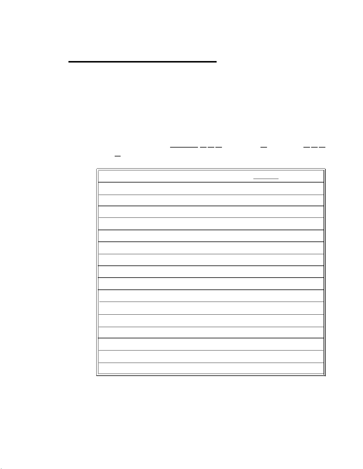
Form 8: Announcements
Each announcement can be up to two minutes in length.
■
■
When programming Automated Attendant, you must create and record all
announcements before creating the Day Menu, Night Menu, or submenu that
refers to it.
■
Make additional copies of this blank form for each announcement that you
want to create.
■
You may create up to 99 announcements.
■
To administer: Press
[4] .
[
Intercom
]
[7] [7] [7] ;
EXTENSION
Announcement No.
[#]
PASSWORD
[#] [9] [3]

Form 9: Group Lists
■
Group Lists provide the ablility to send voice mail messages to multiple
subscribers at one time.
■
When addressing a message, a subscriber can enter [*]
[5] followed by a
Group List Number, rather than entering individual extensions. The system
delivers the message to all the mailboxes on the Group List.
■
Make copies of the Group List form to distribute to the subscribers.
■
You may create up to 99 Group Lists.
■
Each Group List may contain up to 100 entries. An extension can belong to
more than one group.
■
To administer: Press
[
Intercom
]
[7] [7] [7] ;
EXTENSION
[#]
PASSWORD
[5] .
Group List No.
Group Name
Extension
Name
[#] [9]

Form 10: Line Ownership
■
You can provide VMS Line coverage for an outside line, that is dedicated to a
person or project, by designating an extension as the “owner” of the outside
line. If a call coming in on an outside line, that is covered by PARTNER MAIL
Call Answer Service is not answered within four rings, the system transfers
the caller to the mailbox for the extension that owns the line. This allows the
caller to leave a message .
■
Refer to PARTNER II Release 3 Form A to determine Line and Telephone
numbers, and PARTNER II Release 3 Form B1 to determine the Owner’s
extension.
■
Use the form below to assign Line Ownership.
■
To administer: Press
[6] .
[
Intercom
]
[7] [7] [7] ;
EXTENSION
[#]
PASSWORD
[#] [9]
Line
Telephone
Number
Line Owner
Owner's
Extension

Appendix B: Factory Settings
PARTNER MAIL System Factory Settings
B
PARTNER MAIL Parameter
Automated Attendant
Automated Attendant Submenu IDs
Automated Attendant Announcement IDs 1-99
Number of rings before answer 2
System Operator’s Extension 10
Timeout Action Option (No Fax)
Day
Night
Timeout Action Option (With Fax)
Day System Operator
Night
Touch-Tone Gate
Factory Setting
1-99
4 sec./Transfer to:
System Operator
General Mailbox
8 sec./Transfer to:
General Mailbox
OFF
(Continued)
B-1

Appendix B: Factory Settings
PARTNER MAIL System Factory Settings
PARTNER MAIL Parameter
Greetings/Prompts
Voice Mail Greeting
Automated Attendant Greetings
Menu Prompts
Personal Greetings
Name Recordings
Messages
Message Length
Mailboxes
Class of Service
Password
System Operator’s Extension
Factory Setting
2 minutes
10 seconds each
2 minutes each
2 minutes each
4 seconds each
1 sec. - 2 min.
(1 sec. - 5 min for
COS 9 mailboxes)
2
1234
10
B-2
System Administrator’s:
Mailbox
Password
General Mailbox Owner’s:
Extension
Mailbox
Miscellaneous
Group List IDs
Outcalling
9997
1234
10
9999
1 - 99
OFF

Appendix C: PARTNER MAIL
Case Studies
The following case studies provide examples of the planning of the PARTNER MAIL
system for the following features:
■
Company A: Automated Attendant Service as the Delayed Call Handler
■
Company B: Automated Attendant Service as the Immediate Call Handler
■
Company C: Call Answer Service with CO Line Coverage
C
Each case study shows how a fictitious company selects, plans and programs the
features listed above. Use the case studies for ideas on how to implement the
PARTNER MAIL system at your site. Refer to Chapter 3 or Chapter 4 of this guide
for planning procedures. Refer to PARTNER MAIL™ Installation and Use for
programming procedures.
Recording the PARTNER MAIL Features
Each company must record the PARTNER MAIL system features that they require
on the appropriate PARTNER II System Planning forms and on the appropriate
PARTNER MAIL System Planning forms.
PARTNER II System Planning Forms
The PARTNER MAIL system features selected by each company must be entered
on the following PARTNER II Release 3 System Planning forms:
■
System Planner Worksheet
■
Form A: System Configuration
■
Form B1: System Extensions
■
Form B2: Customized Extension Settings
■
Form C: Button Programming Template
C-1

Appendix C: PARTNER MAIL Case Studies
NOTE:
Not all the PARTNER II Release 3 System Planning forms are discussed in
the following examples, nor are all the fields on each form discussed. Only
those items which affect PARTNER MAIL system planning and administration
are highlighted. For a full discussion of the planning forms, see the
instructions which come with the PARTNER II Release 3 System Planner.
NOTE:
Many of the options specified in the following examples, such as the extension
numbers and types of telephones assigned, will vary for each customer.
PARTNER MAIL Planning Forms
There are ten PARTNER MAIL System Planning Forms:
■
Form 1: Mailbox Assignments
■
Form 2: System Parameters
■
Form 3: Voice Mail Greetings
■
Form 4: Automated Attendant Settings
■
Form 5: Automated Attendant Day Greeting and Menu
■
Form 6: Automated Attendant Night Greeting and Menu
■
Form 7: Automated Attendant Submenus
■
Form 8: Automated Attendant Announcements
■
Form 9: Group Lists
■
Form 10: Line Ownership
Each case study presents portions of the appropriate forms as they would be
completed by the company described in the case study.
C-2 Overview

Appendix C: PARTNER MAIL Case Studies
Company A
Company A is a hotel/motel supplies distributor. They take pride in their ability to
provide personalized service and to fill orders quickly. They require the ability to:
■
handle calls when the Customer Service Representatives or receptionist are
busy or not available.
■
take orders at night when no one is available.
■
allow Customer Service Representatives to handle unanswered calls before
they are sent to the PARTNER MAIL system for coverage.
■
transfer calls to a customer service representative’s voice mailbox if the caller
wishes to leave a message.
Selecting the Features
A representative of Company A, with the help of an AT&T representative, selects the
features to meet their requirements (Figure 3-1).
■
Company A wants calls to ring first at the customer service representative's
and the receptionist’s extensions. If they do not answer within 4 rings, calls
are answered by PARTNER MAIL system. To accomplish this, Company A
selects Automated Attendant Service — Delayed Call Handling.
■
The PARTNER MAIL handles all unanswered calls during the day and at
night. Callers hear either the Day Greeting and Menu or the Night Greeting
and Menu. They must select Automated Attendant Service — Always in use.
■
Customers who reach the Automated Attendant Service are routed to the
General Mailbox if they wish to leave orders after hours or when the
receptionist and Customer Service Representatives are busy or are absent.
Set the Dial 0 / Timeout Option to General Mailbox.
■
The receptionist or any customer service representative can transfer callers
directly to another PARTNER MAIL subscriber’s voice mailbox so they can
leave messages. Select Call Answer Service — Direct Transfer to Voice
Mailbox.
Company A
C-3

Appendix C: PARTNER MAIL Case Studies
Incoming
Call
Answered
by fourth
ring?
No
PARTNER
MAIL
Yes
Receptionist Customer Service Customer Service
VM Box
Night Svc
General
Mailbox
Voice Mailbox
Announcement 2
Announcement 1
Day Main Menu
Thank you
for calling
Company A
Representative Representative
VM Box
Voice Mailbox
Voice Mailbox
Customer
Service
Representative
Receptionist
...
General Mailbox
VM Box
Figure 3-1. Call Flow at Company A
C-4 Company A
Sorry!
We're Closed
...
Voice Mailbox

Appendix C: PARTNER MAIL Case Studies
Completing the Planning Forms
Company A, with the assistance of an AT&T representative, completes the
PARTNER II System and PARTNER MAIL system planning forms to indicate the
PARTNER MAIL system features that they selected.
PARTNER II R3 System Planner Worksheet
A salesperson completes the System Planner Worksheet (Figure 3-2) during the
initial meeting with the customer. It contains basic information about how the
customer wants the PARTNER II Communications System configured.
System Planner Worksheet
This worksheet records basic setup decisions for the system.
1. Lines
a. How many lines (total) will be connected to the system?
b. How many lines will be assigned as personal/dedicated lines?
c. How many lines will be assigned to all extensions? (1a – 1b = 1c)
2. Call Handling
Who answers incoming calls for your business during normal business hours? (Check 2a or 2b)
Individual users (all extensions)
a.
b.
Central receptionist (extension 10)
3.
Customizing Extension Settings
✓
1a
1b
1c
2a
2b
User Group
Receptionist
A.
Basic Users
B.
C.
D.
E.
F.
G.
H.
I.
J.
Standard Phone Users
PARTNER Mail (VMS) extensions
K.
4. Voice Mail
To indicate PARTNER Mail (VMS) services you will use, check one or more options: 3a and 3b for
line coverage (see
a. VMS Automated Attendant service (lets callers on specified lines dial extensions or groups directly).
b. VMS Line Coverage (lets callers on a user's personal line leave a message.)
c. VMS Extension Coverage (lets callers for a specific extension leave a message.)
Form A
instructions), or 3c for extension coverage (see
Number of Users
Phone Type
Standard
Not applicable
Form B2).
Figure 3-2. PARTNER II System Planner Worksheet
✓
3a
3b
3c
Company A
C-5

Appendix C: PARTNER MAIL Case Studies
■
3K. PARTNER Mail (VMS) extensions: The number entered here depends
on the number of voice processing cards the customer ordered (one or two).
Company A has two voice mail extensions (one voice-processing card).
■
4. Voice Mail: Specifies which Voice Mail Services are used. Company A
wants Automated Attendant Service coverage on all lines. They do not require
VMS Line coverage or VMS Extension coverage.
PARTNER II System Planner Form A
Form A (Figure 3-3) shows the basic configuration of the PARTNER System.
7 System Lines Number of Lines (#104)
Line
Telephone Number
Jack
No
01
02
03
04
05
06
07
08
09
10
11
12
13
14
15
16
17
18
19
20
21
22
23
24
Line Type
(#201)
Line Coverage
Line Owner (#301)
Caller
ID?
Other Subscription
Services
8. System Settings. Check if applicable: 10. Auxiliary Equipment (Extensions) Check if
9. Auxiliary Equipment (System) Check if applicable:
Figure 3-3. PARTNER II System Planner Form A
■
7. System Lines — Line Coverage: Indicates how the system covers
incoming calls. VMS-AA means that the Automated Attendant Service covers
the lines. Company A wants Automated Attendant Service on all lines.
❑ Transfer Return Rings (#105)___
❑ Outside Conference Denial (#109)
❑ Toll Call Prefix (#402) not required
❑ System Password (#403) __ __ __ __
❑ Emergency Telephone Number List (Form D)
✓
❑ Night Service Button (#503)
❑ Music on Hold (#602)
❑ SMDR Record Type (#608):
❑ All calls
❑ Outgoing calls only
❑ Loudspeaker Paging
Number of zones_____
✓
❑ PARTNER MAIL Automated Attendant Service
VMS Hunt Delay (#506)
❑ Immediate call handling
✓
❑ Delayed call handling
VMS Hunt Schedule (#507):
✓
❑ Always (with Day/Night schedules)
❑ Day only
❑ Night only
❑ IROB Protectors
❑ EMI Filters
❑ Uninterruptible Power Supply
❑ Caller ID Devices
applicable.
❑ Hotline (#603)
List paths of Hotline/alert extensions below
❑ Doorphone 1 Extension (#604): ___
To signal extensions (#606):
❑ Doorphone 2 Extension (#605): ________
To signal extensions (#606):
❑ PARTNER Attendant (#607)
■
■
C-6 Company A
8. System Settings — Night Service Button: Company A requires a Night
Service Button because they wish to have the Automated Attendant Service
answer calls at night with a different Night Greeting and Menu.
9. Auxiliary Equipment — PARTNER MAIL Automated Attendant Service:
Company A wishes to use the Automated Attendant Service.

Appendix C: PARTNER MAIL Case Studies
■
9. Auxiliary Equipment — VMS Hunt Delay — Delayed Call Handling:
Setting the VMS Hunt Delay for delayed call handling allows Company A’s
receptionist and Customer Service Representatives to answer the call first.
■
9. Auxiliary Equipment — VMS Hunt Schedule — Always: Setting the VMS
Hunt Schedule to Always tells the Automated Attendant Service to answer
calls during the day and
at night (when the Night Service Button is ON).
Company A
C-7

Appendix C: PARTNER MAIL Case Studies
PARTNER II System Planner Form B1
Form B1 (Figure 3-4) is used to record extension information such as the name of
each extension user and the equipment connected to each extension.
Figure 3-4. PARTNER II System Planner Form B1
■
■
■
C-8 Company A
Name/Description: Indicates the name of each PARTNER MAIL system
subscriber. It also indicates the two extensions being used for VMS and for
the Remote Maintenance Device (RMD) required with the PARTNER MAIL
system.
Aux. Eq.: Indicates the type of auxiliary equipment connected to the
PARTNER II System’s extension jacks. For the RMD, “MD” is written into the
Other column to indicate that a modem is connected to this extension jack.
An “X” is written into the VMS column for each PARTNER MAIL extension.
User Group ID: Identifies groups of extensions which have the same settings
(specified on Form B2). A single extension may be included in its own User
Group if it has unique customized settings. All VMS extensions must be
assigned to the same User Group (Group K in this example).
The RMD must be assigned to its own user group (group D in this example)
so that all lines will be removed.

Appendix C: PARTNER MAIL Case Studies
■
Trans. Return Ext.: For VMS extensions, set the Transfer Return Extension
to the receptionist’s extension. When the system transfers a call to an
extension, and that extension does not answer, the call returns to the
receptionist for handling.
PARTNER II System Planner Form B2
Form B2 (Figure 3-5) is used to list extensions which have settings (line assignment,
line ringing, etc.) that differ in any way from the default settings listed in the second
row.
Figure 3-5. PARTNER II System Planner Form B2
■
Line Assignment and Line Ringing: Company A requires all lines to ring
immediately at the receptionist and the Customer Service Representatives’
extensions. Notice that in this example, three of the lines appear at other
extensions but do not ring there. These representatives are not expected to
answer calls but they can use the lines to place outside calls.
■
Auto. Ext. Privacy: All calls to an extension are private and no other
extension can join the call. Make sure that Auto Extension Privacy is not
assigned (this is the default setting) to the PARTNER MAIL system extensions
when using the Automated Attendant Service as a Delayed Call Handler. In
Company A, this allows the receptionist or the Customer Service
Company A
C-9

Appendix C: PARTNER MAIL Case Studies
Representatives to pick up the call after the Automated Attendant Service has
answered it. The PARTNER MAIL system then automatically disconnects from
the call.
The RMD requires Auto. Extension Privacy so that maintenance calls are not
interrupted.
PARTNER II System Planner Form C
Form C (Figure 3-6 and Figure 3-7) is used for assigning button features to
telephones. There is a different form for each model of MLS telephone and one for
the Intercom Autodialer.
Figure 3-6. PARTNER II System Planner Form C for Receptionist’s Extension
■
C-10 Company A
Company A's receptionist needs a Night Service button to activate Night
Service, a Voice Mailbox button to transfer callers to other subscriber’s voice
mailboxes, and a VM Messages button programmed for one-touch message
retrieval.
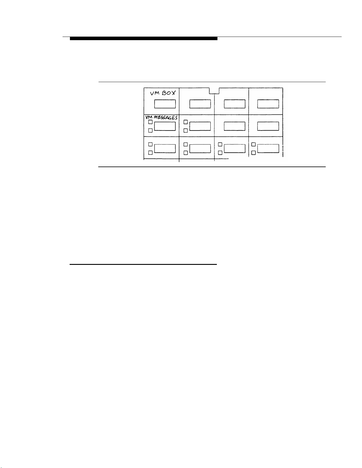
Appendix C: PARTNER MAIL Case Studies
Figure 3-7. Form C for Representative’s Extension
■
Customer Service Representatives require a Voice Mailbox button on their
phones to transfer callers directly to any representative’s voice mailbox.
■
All subscribers need a VM Messages button to dial into the PARTNER MAIL
system with one touch to retrieve messages. They can also use this button to
transfer subscribers who are calling in from outside and wish to be transferred
to the PARTNER MAIL system in order to retrieve their messages.
Programming PARTNER II to Support PARTNER MAIL
Based on the entries on the PARTNER II System Planning forms, an implementor or
programmer performs the following PARTNER II programming procedures for
Company A:
1.
Hunt Group Extensions (#505): All extensions attached to ports on the
PARTNER MAIL unit must be assigned to Hunt Group 7.
2.
Transfer Return Extension (#306): Set the Transfer Return Extension on all
VMS extensions to extension 10, the receptionist.
3.
Line Assignment (#301): Remove all existing line assignments from the RMD
extension so that incoming calls will not be answered.
— Remove lines 04 through 09 from User Group B (Basic Users).
4.
Auto Extension Privacy (#304): Assign Auto Extension Privacy to the RMD
extension so that no one can interrupt maintenance calls.
VMS Hunt Delay (#506): Select 2 Delayed. This sets a four-ring delay
5.
before CO (Central Office) calls on lines administered to Hunt Group 7 are
answered by the PARTNER MAIL system. This gives the receptionist and the
Customer Service Representatives time to answer the call first.
Company A
C-11

Appendix C: PARTNER MAIL Case Studies
VMS Hunt Schedule (#507): Leave the factory setting, 1 Always. With this
6.
setting the Automated Attendant Service provides backup during the day and
at night.
Group Call Distribution (#206): Used to assign all nine outside lines to Hunt
7.
Group 7 (the PARTNER MAIL system Hunt Group). Select 1 Assigned so
that the incoming lines are answered by the Automated Attendant Service.
Night Service Button (#503): Assign a Night Service button to extension 10
8.
so that Night Service can be activated. When Night Service is ON, the
Automated Attendant Night Service Greeting plays for callers.
9.
Program a Voice Mailbox button (F14) on all extensions indicated on Form C.
(There will be multiple copies of Form C).
10.
Program a VM Message button for all subscriber’s phones.
PARTNER MAIL System Planning Forms Used by Company A
Company A must complete forms 1 through 8.
■
Company A does not complete Form 3 because the Voice Mail Greeting is not
being changed.
■
Company A does not complete Form 7 because submenus are not being
used.
■
Company A will complete Form 8 to provide scripts to record announcements,
but the scripts are not shown in this case study.
■
Completion of Form 9 depends on whether Company A uses Group Lists with
the Voice Mail Service. They are not shown in this case study.
■
Company A does not complete Form 10 because they are not using the Line
Coverage feature.
This section shows how Company A completed the PARTNER MAIL Planning forms
1, 2, 4, and 5. Form 6 is not shown since it is completed similarly to Form 5.
C-12 Company A

Appendix C: PARTNER MAIL Case Studies
PARTNER MAIL Form 1
Form 1 is used to record the extension, name and Class of Service (COS) of each
subscriber who is assigned a mailbox.
Mailbox
Name
COS
Letter Key
Figure 3-8. PARTNER MAIL Planning Form 1
■
Mailbox: Indicates the extension number for each subscriber. Note that the
extension number corresponds to the mailbox number.
■
Name: Company A lists each subscriber’s first name, in all capital letters,
since this is the name that will be recorded for the directory.
■
COS: The class of service for the mailbox. The COS indicates the message
storage capacity for the mailbox, the transfer type, and whether or not
outcalling is assigned. A COS of 2 is the default for all mailboxes. Since
Company A intends to use the default setting, no entries are required in the
COS field.
■
Letter Key: Enables Company A to translate up to four characters of each
subscriber’s first or last name. This enables Company A to enter each
subscriber’s name into a directory. Callers can use the directory to reach
subscribers by dialing their first or last name. Since Company A intends to list
callers in the directory by first names, they entered each subscriber’s first
name in all capital letters, and used the letter key to translate the first four
characters of the first name.
Company A
C-13
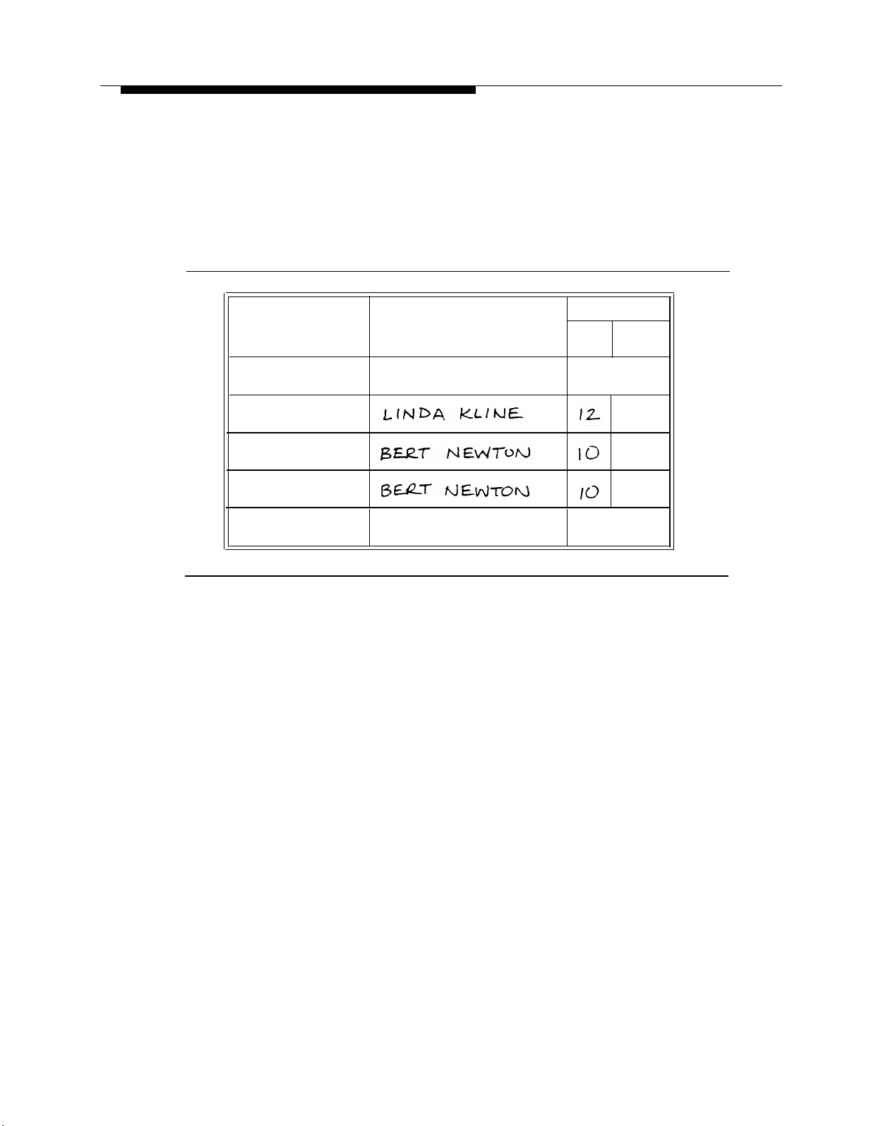
Appendix C: PARTNER MAIL Case Studies
PARTNER MAIL Form 2
Form 2 enables Company A to determine which subscribers are responsible for the
administration and maintenance of the system.
Position Name
Fax Extension or Fax
Hunt Group Extension
System Administrator
General Mailbox Owner
System Operator
Fax Message Receiver
Mailbox
EXT.
Factory
Setting
9997 ✔
10
✔
10 ✔
Figure 3-9. PARTNER MAIL Form 2
■
System Administrator: Linda Kline at extension 12 is responsible for
administering the PARTNER MAIL system.
■
General Mailbox Owner and System Operator: Bert Newton at extension 10
is the System Operator and the General Mailbox Owner. Bert, the receptionist,
handles calls if the representatives are busy, switches the system from day
operation to night operation, and checks the General Mailbox for messages
when the message light on his telephone is lit.
C-14 Company A
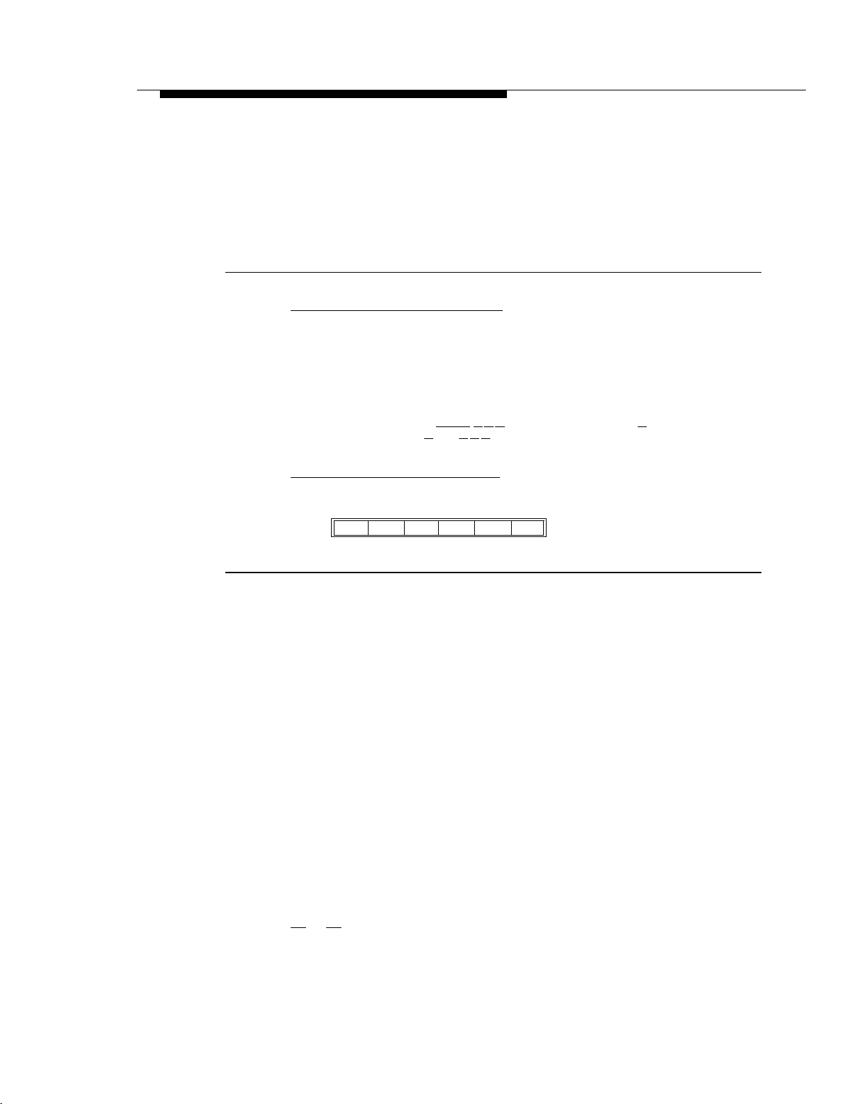
Appendix C: PARTNER MAIL Case Studies
PARTNER MAIL Form 4
Form 4 enables Company A to set the PARTNER MAIL system’s system-wide
settings.
Touch-Tone Gate
■
The Touch-Tone Gate is automatically set to ON if the system is used for Fax
Call Handling.
■
Check one:
ON
❏
❏
✓
OFF
✔
■
To administer: Press
and
PASSWORD
Extensions in Enter Plan
■
Check the first digit of each extension used in the dial plan.
[#] Press [9] [3] [5]
[
Intercom
]
[7] [7] [7] . Enter administrator’s
.
EXTENSION
[#]
✓
❏
1
Figure 3-10. PARTNER MAIL Form 4
■
Touch-Tone Gate: Since all of Company A’s clients call from touch-tone
phones, they have decided to leave the Touch-Tone Gate setting at the
default of OFF.
■
Extensions in Dial Plan: Company A checked 1, 2, and 7. When planning
the Day or Night Main menus, Company A should refer to Form 4 as a
reminder not to assign the 1, 2 or 7 keys as Selector Codes. That way, when
callers dial extensions beginning with 1, 2, or 7 from a menu, the system
transfers them directly to the extension.
Day Greeting and Menu Scripts
Company A uses the Automated Attendant as a backup to their receptionist and
Customer Service Representatives. Callers hear the Day Greeting and Menu only
when no one is available to answer the call. Company A defined their Day Main
Menu so that Selector Codes 1, 2 and 7 are reserved for Direct Extension Transfer.
Selector Codes 3 and 4 cause the system to play an announcement when the caller
presses a [3]
or [4] from the Day Main Menu.
4
❏
5
❏
7
2
❏
✓
3 ❏
❏
✓
Company A
C-15

Appendix C: PARTNER MAIL Case Studies
Announcements must exist before the System Administrator can enter them as part
of the Day Main Menu. The announcements are not illustrated in this example. Refer
to Chapter 3 for instructions on how to complete Form 8 for announcements.
Company A's Day and Night greetings are shown in Figure 3-1. Since callers only
hear the Day Menu when all extensions are busy or cannot answer, Company A set
the Dial 0 / Timeout to General Mailbox so that callers can leave a message (see
Figure 3-11).
Day Menu Definition
Selector Selector
Code
Code
Action*
1
2
3
4
5
6
7
8
9
Number
(5 ✔ )
(5 ✔ )
(5 ✔ )
(5 ✔ )
(5 ✔ )
Description
Day Menu Script
*Selector Code Action Key
Selector Code Transfer
1
Play an existing submenu
2
Play an existing announcement
3
Prompted transfer
4
5
Direct extension transfer
✔
Figure 3-11. Day Menu Definition and Script
Instructions for completing the all PARTNER MAIL System Planning forms are in
Chapter 3 of this document.
C-16 Company A

Appendix C: PARTNER MAIL Case Studies
Administering the PARTNER MAIL System
Based on the PARTNER MAIL System Planning forms, Company A’s System
Administrator performs the administration shown below. These procedures are meant
only as an overview. Detailed instructions for administering the system are found in
Chapter 4 and Chapter 6 of the PARTNER MAlL™ Installation and Use document.
To administer the PARTNER MAIL system:
1.
— Press
[
Intercom
]
[7] [7] [7] ,
— Enter the administrator’s EXTENSION and press [#] ,
— Enter the administrator’s PASSWORD and press [#]
to administer the system.
to administer the System Parameters shown on Form 2.
to administer the Mailboxes shown on Form 1.
to administer the System Greetings shown on Forms 5 and 6. Then:
to administer the Automated Attendant Greetings.
2.
3.
4.
— Press [9]
Press [1]
Press [4]
Press [7]
— Press [3]
— Record the Day Greeting (Form 5).
— Record the Night Greeting (Form 6).
5.
Press [3]
to administer the Automated Attendant, and record Company A’s
announcements as shown on Form 8.
6.
Press [3]
to administer the Automated Attendant, then:
— Record the Day Main Menu (Form 5).
— Record the Night Main Menu (Form 6).
.
Company A
C-17

Appendix C: PARTNER MAIL Case Studies
Company B
Company B is a mortgage agency. They have the following requirements:
All calls are answered by the PARTNER MAIL Automated Attendant Service
■
with overflow calls being handled by the receptionist.
■
The system transfers calls to the appropriate extensions or groups during the
day.
■
Unanswered calls are sent to the receptionist during the day and to the called
party’s voice mailbox during the night.
■
Fax Call Handling for Company B’s three fax machines.
A guest voice mailbox for visiting realtors and lawyers. These visitors will not
■
have their own extensions but have use of their own mailbox which they may
call remotely.
Selecting the Features
A representative of Company B, with the help of the implementor, selects the
following features (Figure 3-12):
■
Company B wants to use the system to handle most of its calls. Their
receptionist will only answer overflow calls. They want the system to transfer
callers with rotary telephones to the receptionist. To accomplish this, Company
B selects Automated Attendant Service – Immediate Call Handling
■
Callers hear either the Day Greeting and Menu or the Night Greeting and
Menu and may transfer to the desired group or extension. Company B selects
Automated Attendant Service – Always in use.
■
Fax Call Handling automatically recognizes fax transmissions and routes them
to the Fax Hunt Group.
■
Company B wants to give subscribers the ability to turn VMS coverage ON
when they leave, and turn it OFF during the day when unanswered calls are
routed to the receptionist. They select Call Answer Service – Extension
Coverage: A VMS Cover button is assigned at each extension.
■
Although each PARTNER II extension is assigned a voice mailbox to receive
messages after hours, Company B requires a special Guest Mailbox with
Class of Service 7 (Transfer Not Permitted) for visitors who are not assigned
their own telephones. The PARTNER MAIL Automated Attendant Service
does not attempt to transfer calls to the extension associated with this
mailbox. Instead, it connects the caller directly to the voice mailbox. Guests
can retrieve their voice mail messages from any touch-tone telephone. Guest
Mailboxes should be assigned a two-digit extension number which is not
being used.
C-18 Company B

Appendix C: PARTNER MAIL Case Studies
Incoming
Call
Receptionist
Ext. 10
Announcement 2
Announcement 1
VM Cover
VM Msgs
Night Svc
Agent
Ext. 14
VM Cover
VM Msgs
FAX?
No
– VMS Extension
Coverage ON
– Dial 0 Timeout =
General Mailbox
– Caller Dials Ext. 53
Agent
VM Cover
VM Msgs
Ext. 15
Yes
Voice Mailbox
Voice Mailbox
General
Mailbox
Figure 3-12. Company B’s Call Handling Flow
Voice Mailbox
Guest Mailbox
Ext 53
Fax Extension
Hunt Group
776
Company B
C-19

Appendix C: PARTNER MAIL Case Studies
Completing the Planning Forms
Company B, with the assistance of an AT&T representative, completes the
PARTNER II System and PARTNER MAIL System Planning forms to indicate the
PARTNER MAIL system features that they selected.
PARTNER II System Planner Worksheet
A salesperson completes the System Planner Worksheet (Figure 3-13) during the
initial meeting with the customer. It contains basic information about how the
customer wants the PARTNER Communications System configured.
1. Lines
How many lines (total) will be connected to the system?
a.
b.
How many lines will be assigned as personal/dedicated lines?
c.
How many lines will be assigned to all extensions? (1a – 1b = 1c)
2. Call Handling
Who answers incoming calls for your business during normal business hours? (Check 2a or 2b)
Individual users (all extensions)
a.
b.
Central receptionist (extension 10)
3.
Customizing Extension Settings
1a
1b
1c
2a
2b
User Group
Receptionist
A.
B.
Basic Users
C.
D.
E.
F.
G.
H.
I.
J.
Standard Phone Users
K.
PARTNER Mail (VMS) extensions
4. Voice Mail
To indicate PARTNER Mail (VMS) services you will use, check one or more options: 3a and 3b for
line coverage (see
VMS Automated Attendant service (lets callers on specified lines dial extensions or groups directly).
a.
b.
VMS Line Coverage (lets callers on a user’s personal line leave a message.)
c.
VMS Extension Coverage (lets callers for a specific extension leave a message.)
Form A
instructions), or 3c for extension coverage (see
Number of Users
Phone Type
Standard
Not applicable
Form B2).
Figure 3-13. PARTNER II Planning Worksheet
3D.: Lists the fax extensions. Company B wants Fax Call Handling so their
■
three fax extensions are put into a Group (Group D in this example) so they
can be assigned the same extension settings.
3K. PARTNER Mail (VMS) extensions: The number entered here depends
■
on the number of voice processing cards the customer ordered (one or two).
Company B has two voice mail extensions (one voice processing card).
✓
✓
3a
3b
3c
C-20 Company B
 Loading...