

Page 1

Lucent Technologies
PARTNER MAIL™
Bell Labs Innovations
Voice Messaging System
Installation and Use
Lucent Technologies -
formerly the communications
AT&T
systems and technology
units of AT&T
585-322-101
Issue 1
Page 2

585-322-101
Issue 1
Intellectual property related to this product (including trademarks) and registered to AT&T
Corporation has been transferred to Lucent Technologies Incorporated.
Any references within this text to American Telephone and Telegraph Corporation or AT&T should
be interpreted as references to Lucent Technologies Incorporated. The exception is cross
references to books published prior to December 31, 1996, which retain their original AT&T titles.
Lucent Technologies – formed as a result of AT&T's planned restructuring - designs, builds, and
delivers a wide range of public and private networks, communication systems and software,
consumer and business telephone systems, and microelectronic components. The world-renowned
Bell Laboratories is the research and development arm for the company.
Page 3

CAUTION:
Environmental and electrical conditions must meet the specifications as listed
on pages 20 and 21.
SAVE THESE INSTRUCTIONS
Page 4

Important Safety Instructions
Always follow these basic safety precautions when using the system:
1.
Read and understand all instructions.
Follow all warnings and instructions marked on the product.
2.
Never spill liquid on the product or drop objects into the ventilation slots and
3.
openings. Doing so may result in serious damage to the components.
4.
Repair or service must be performed by a qualified repair person.
5.
The product is provided with a three-wire grounding type plug. This is a
safety feature. DO NOT defeat the safety purpose of the grounding type plug.
DO NOT staple or otherwise attach the AC power supply cord to building
surfaces.
DO NOT use the product near water or in a wet or damp place (such as a wet
6.
basement).
CAUTION:
DO NOT block or cover the ventilation slots and openings. They prevent the
product from overheating. DO NOT place the product in a separate enclosure
unless proper ventilation is provided.
Additional Safety Instructions for Installation Personnel
1.
DO NOT install telephone wiring during a lightning storm.
2.
DO NOT install telephone jacks in a wet location unless the jack is specifically
designed for wet locations.
3.
Never touch uninsulated telephone wires or terminals, unless the telephone
line has been disconnected at the network interface.
4.
Use caution when installing or modifying telephone lines.
The system carriers must be securely wall mounted.
5.
CAUTION:
If any wiring from the extension jacks leaves the building premises, you must
install AT&T IROB protectors (see “Requirements for Out-of-Building
Extensions” on page 21).
CAUTION:
Use only AT&T - manufactured PARTNER modules in the PARTNER II
Communications System.
Page 5

Contents
About This Guide
■
How to Use this Guide
■
Conventions
■
Related Guides
1
2
Introduction
■
Responsibilities
■
System Services and Features
Installation
■
Preparing for Installation
■
Installing the PARTNER MAIL Unit
■
Add or Replace Voice-Processing Card
viii
x
xi
1-1
1-2
1-4
2-1
2-2
2-4
2-12
3
PARTNER II System Programming
■
PARTNER II System Planning Forms
■
Introduction to System Programming
■
Initial System Programming
■
Programming Automated Attendant
■
Programming Call Answer Service
■
Programming Night Service (#503)
■
Telephone Button Programming
3-1
3-2
3-3
3-5
3-8
3-10
3-12
3-13
i
Page 6

Contents
4
5
PARTNER MAIL - Initial Programming
■
Introduction to Programming
■
Before Programming
■
Programming System Parameters
■
Programming the Schedule
■
Program Automated Attendant Menus
■
Programming System Greetings
■
Modifying Mailboxes
■
Creating Group Lists
■
Assigning Line Ownership
Verifying System Operation
■
Automated Attendant Service
■
Call Answer Service
■
Voice Mailbox Transfer
4-1
4-2
4-5
4-7
4-14
4-17
4-25
4-28
4-31
4-33
5-1
5-2
5-4
5-5
■
Voice Mail Service
6
PARTNER MAIL Administration
■
Guidelines for Administration
■
Administration Menu Hierarchy
■
Planning Forms
■
Accessing the Main Menu
■
Changing System Parameters
■
Changing the Schedule
■
Changing the Main Menus
■
Changing Mailbox Assignments
■
Changing Group Lists
■
Changing Line Ownership
5-6
6-1
6-2
6-3
6-5
6-6
6-7
6-11
6-15
6-31
6-42
6-47
ii
Page 7

Contents
■
Changing Greetings
■
Voice Mail Service
6-51
6-56
7
A
Troubleshooting
Appendix A: Factory Settings
Glossary
Index
7-1
A-1
G-1
IN-1
iii
Page 8

Figures
1
2
Introduction
1-1.
1-2.
1-3.
Overview of PARTNER MAIL Services
PARTNER MAIL System as Immediate Call Handler
PARTNER MAIL System as Delayed Call Handler
Installation
2-1.
2-2.
2-3.
2-4.
2-5.
2-6.
2-7.
2-8.
2-9.
2-10.
2-11.
2-12.
2-13.
PARTNER MAIL Unit
Wall-Mounting the PARTNER MAIL Unit
Mounting the PARTNER MAIL Unit
Connect PARTNER MAIL to PARTNER System
PARTNER MAIL Unit - Rear Panel
PARTNER MAIL RMD Switch Settings
The PARTNER MAIL Remote Maintenance Device
Remove Unit from Wall-mount
Remove Screw from Unit
Voice Processing Card Switch Settings
Installing a Voice Card
Installing the Cover
Mounting the PARTNER MAIL Unit
1-1
1-5
1-8
1-9
2-1
2-4
2-5
2-6
2-8
2-9
2-10
2-11
2-13
2-14
2-15
2-16
2-17
2-18
4
PARTNER MAIL - Initial Programming
4-1.
4-2.
4-3.
4-4.
4-5.
4-6.
4-7.
4-8.
PARTNER MAIL System Programming Menus
Programming PARTNER MAIL System Parameters
Programming the Schedule
Automated Attendant
System Greetings
Programming Mailboxes
Group Lists
Line Ownership
4-1
4-3
4-7
4-14
4-17
4-25
4-28
4-31
4-33
iv
Page 9

Figures
6
PARTNER MAIL Administration
6-1.
6-2.
6-3.
6-4.
6-5.
6-6.
6-7.
6-8.
Administration Menu Hierarchy
System Parameters
Schedule
Changing the Automated Attendant Main Menus
Mailbox Administration Options
Changing Group Lists
Line Ownership
System Greetings
6-1
6-4
6-7
6-11
6-15
6-31
6-42
6-47
6-51
v
Page 10

About This Guide
This guide provides instructions for installing, administering and maintaining the
PARTNER MAIL
TM
Voice Messaging System on the PARTNER® II Release 3
Communications System. This guide is intended for technicians who install, maintain,
and repair communications systems and implementors who initially program the
system.
In addition to installation and administration instructions, this guide contains a table
of factory settings in Appendix A, a glossary of terms, an index, and three removable
pages located at the back of the guide. These pages provide the following:
■
Instructions for using the General Mailbox, which you should give to the
System Operator or to whomever in your company is responsible for
maintaining the General Mailbox.
■
A chart showing all of the PARTNER MAIL system functions that are
administered from the Administration Main Menu.
■
A form for providing feedback on this guide, which you can fax or mail to
AT&T.
vii
Page 11

About This Guide
How to Use this Guide
Refer to the following table for a list of Installation, Programming, and Administration
items, the tasks under each, and corresponding chapter number.
ITEM
Installing the
PARTNER MAIL
system
Programming
PARTNER II for
PARTNER MAIL
Initial Programming Program System Parameters Chapter 4
of the PARTNER Program the Schedule
MAIL system Program Automated Attendant
TASKS
Wall-Mount the Unit Chapter 2
Connect the PARTNER MAIL
system to PARTNER II Release
3
Connect the RMD
Add Voice-Processing Card(s)
Initial Programming Chapter 3
Program Automated Attendant
Service
Program Call Answer Service
Program Night Service Button
Program for the RMD
Program Telephone Buttons
Greetings
Program Automated Attendant
Menus
Program Mailboxes
Create Group Lists
Program Line Ownership
CHAPTER NUMBER
Performing
Acceptance Tests
Performing System
Administration Items” in the next section.
Troubleshooting
viii How to Use this Guide
Test Automated Attendant
Service
Test Call Answer Service
Test Voice Mail Service
Refer to “Administration Menu Chapter 6
Identify and correct problems
with the PARTNER MAIL
system.
Chapter 5
Chapter 7
Page 12

About This Guide
Administration Menu Items
Refer to the following table for a list of Administration Menu items, and the tasks
under each. All Administration menu items are documented in Chapter 6.
MENU ITEM
1. System Parameters Program Fax Extension
2. Schedule Parameters Change the System Date and Time
3. Automated Attendant
4. Mailboxes Create, change, and delete
5. Group Lists Scan, delete and modify
6. Line Ownership Review, assign, modify and delete
7. System Greetings
TASKS
Program System Operator Extension
Program General Mailbox Owner
Assign System Administrator’s
Extension
Program Fax Message Receiver
Temporary Schedule Changes
Program Selector Code Actions
Create Submenus
Create Announcements
Change Main Menus
Record prompts
Change Automated Attendant Greetings
Change Voice Mail Greeting
How to Use this Guide
ix
Page 13

About This Guide
Conventions
The following conventions are used throughout this guide:
EXTENSION means press the buttons on the dialpad for the appropriate extension.
] means press the pound button. The pound button is frequently used as a
[ #
termination character, enabling the system to detect the end of an extension or
password you have entered.
PASSWORD means press the buttons on the dialpad for the appropriate password.
MAlLBOX means press the buttons on the dialpad to dial the Mailbox number of a
subscriber. Usually the Mailbox number is a subscriber’s extension.
] means press the star button on the dialpad.
[ ✱
The prompts or responses played by the system are shown in this manner:
Record at the tone.
✔ means that the programmable setting to the left of the ✔ is the factory setting.
x Conventions
Page 14

About This Guide
Related Guides
The following guides are available to help you set up, use, and maintain the
PARTNER MAIL system when it is installed with the PARTNER
®
II Release 3
Communications System.
OU can order additional copies of the related system guides listed in the following
Y
table from the AT&T Customer Information Center. Phone numbers are listed on the
inside front cover.
Portions of the documentation may be available in French and Spanish. For more
information, contact your AT&T authorized representative.
Guide Title
Order Number
PARTNER MAIL system
Installation and Use
Planning Guide and Forms
User’s Quick Reference
585-322-101
585-322-501
585-322-701
PARTNER II Release 3 Communications System
Programming and Use
System Planner
Quick Reference for Use with MLS-Series Telephones
Installation
518-455-311
518-455-315
518-455-306
518-455-313
Related Guides
xi
Page 15

Introduction
The PARTNER MAIL Voice Messaging System is a single unit that adds the
capabilities of Automated Attendant service, Call Answer Service, and Voice Mail
Service to the PARTNER II Release 3 Communications System.
The PARTNER MAIL system automates call handling by answering calls and
presenting the caller with a menu of options so that the call can be routed directly to
the desired extension. The PARTNER MAIL system routes calls and fax
transmissions, answers calls, provides after-hours service and allows subscribers to
send and receive messages.
1
The PARTNER MAIL system is available in two configurations: single voice
processing card (2-port) and two voice processing cards (4-port).
A Remote Maintenance Device (RMD) is included to provide AT&T Service
personnel remote access to the PARTNER MAIL system.
1-1
Page 16

Introduction
Responsibilities
Take a moment to identify the personnel resonsible for planning, installing,
programming, and maintaining the PARTNER MAIL system. With the exception of
the Implementor / Technician, the all of the remaining functions could be performed
by a single person.
System Planner
The system planner works closely with the PARTNER II System Manager to
coordinate the programming. (In many companies, the System Administrator for the
PARTNER MAIL system and the System Manager for the PARTNER System are the
same person.) The two systems must function as an integrated unit.
Implementor / Technician
The implementor or technician installs the PARTNER MAIL system and performs the
initial programming. An implementor or technician must also program the initial
settings for the PARTNER System to integrate it with the PARTNER MAIL system.
The implementor needs the completed planning forms to program the systems.
System Administrator
The PARTNER MAIL System Administrator maintains the PARTNER MAIL system
by modifying mailboxes, changing menus and greetings, and reporting any system
problems. The System Administrator should provide a copy of the procedure titled
Forwarding General Mailbox Messages to the General Mailbox Owner. This
procedure is included at the back of this guide.
General Mailbox Owner
Messages that are not directed to a subscriber's mailbox may be stored in the
General Mailbox. The General Mailbox Owner forwards messages from the General
Mailbox to the intended subscriber’s mailbox. The System Administrator should
provide a copy of the procedure titled Forwarding General Mailbox Messages to the
General Mailbox Owner. This procedure is included at the back of this guide.
1-2 Responsibilities
Page 17

Introduction
System Operator
The System Operator is the receptionist or system user who is primarily responsible
for answering calls. Typically, this person is also the General Mailbox Owner.
Fax Message Receiver
The Fax Message Receiver is the person to notify whenever a fax is received at a
fax extension.
Responsibilities
1-3
Page 18

Introduction
System Services and Features
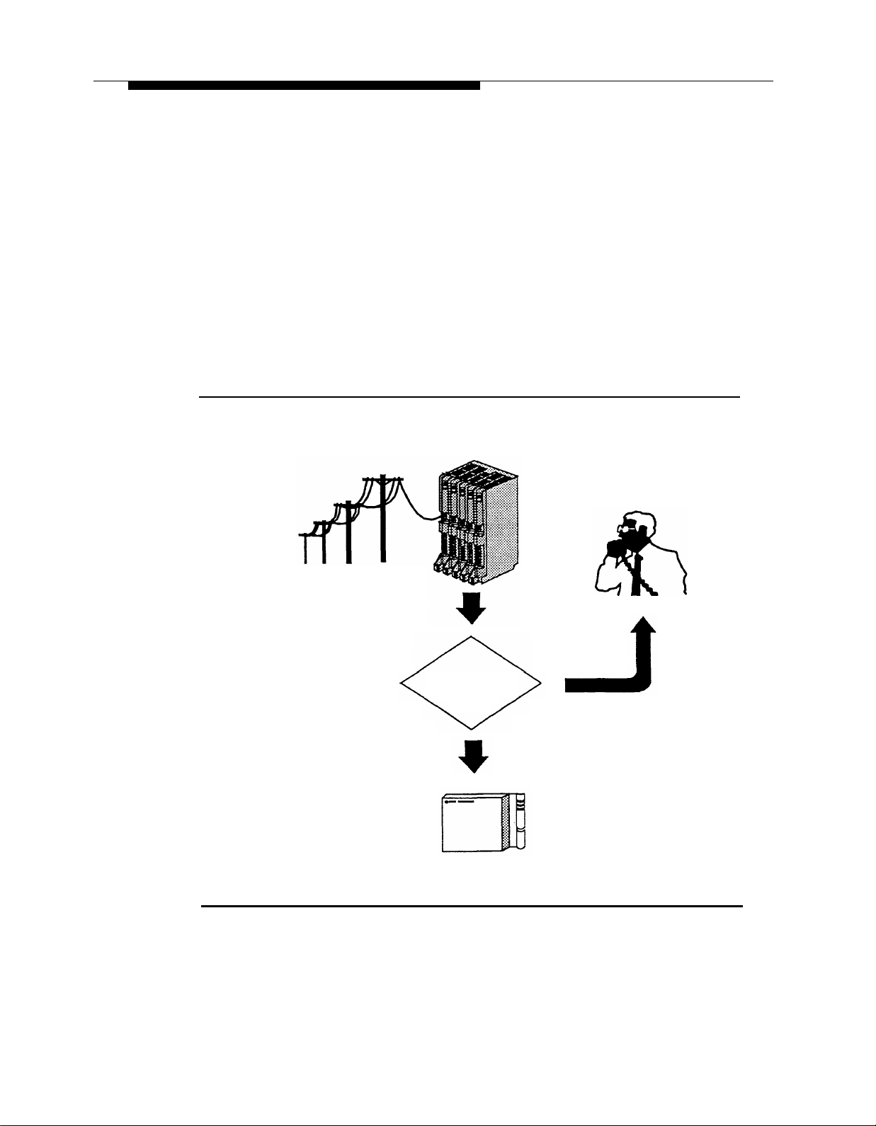
Figure 1-1 provides an overview of the sevices offered by the PARTNER MAIL
system. Read the following descriptions of the Automated Attendant service, Call
Answer Service, Voice Mail Service and their related features; then keep in mind the
type of service and features your company needs.
1-4 System Services and Features
Page 19

Introduction
PARTNER MAIL
Voice Messaging System
Auto Attendant Service
Prompts caller to make a
choice from a menu of
options, then routes the call
to selected destination.
Always
PARTNER
System always
routes calls to
Automated
Attendant
Service
Day Only
PARTNER
System routes
calls to Automated Attendant Service
when night
service is
inactive.
Immediate
Call Handling
Automated Attendant
answers all external
calls immediately. The immediately. OverReceptionist answers
overflow calls.
Call Handling
The Receptionist
answers external calls
flow calls go to the
Automated Attendant
after a delay.
Voice Mail Service
Allows subscribers to:
■
Send Messages
■
Listen to Messages
■
Forward Messages
■
Delete Messages
■
Reply to Messages
■
Select personal operator
■
Record Personal Greeting
Night Only
PARTNER
System routes
calls to Automated Attendant Service
when night
service is
active.
Delayed
Prompts the caller to leave
a message or transfer to
another extension when the
called party does not
answer.
Extension
Coverage
PARTNER
System
Manager
assigns
Automatic
VMS cover to
an extension.
Coverage
Assign VMS
line cover for
a Iine and
associate a
mailbox with
that line.
Coverage ON/OFF
Subscribers turn VMS
cover on and off at
their extension.
Call Answer Service
Line
Voice Mailbox
Transfer
System users
press a
button to
transfer calls
to a voice
mailbox without ringing an
extension.
Outcalling
Notifies subscribers at
remote telephones or
beepers that a new
message is in their
mailbox.
FAX Call Handling
Recognizes an incoming FAX
message and routes it to the FAX
extension or hunt group.
Figure 1-1. Overview of PARTNER MAIL Services
System Services and Features
1-5
Page 20

Introduction
Automated Attendant Service
The Automated Attendant service consists of a greeting and a multi-level menu,
which provides callers with a number of options that enable them to reach an
extension, a group of extensions, or obtain information, by pressing a single digit or
by dialing an extension number.
This service provides several benefits to callers and your company. The Automated
Attendant service:
■
Efficiently routes calls to the correct party.
■
Prompts the caller to leave a message or try another extension if the called
party does not answer or the phone is busy.
■
Enables the caller to access the dial-by-name directory if they do not know the
extension that they need.
■
Plays announcements of frequently requested information (such as directions
or business hours) as menu options, thereby freeing an employee’s time for
other tasks.
■
Receives and transfers fax calls to a designated extension(s).
The PARTNER MAIL Automated Attendant service is useful for many businesses,
such as banks, insurance agencies, post offices, and stores. A bank could, for
example, use Automated Attendant service to allow its customers to select
information from a multi-level menu. This information could include current mortgage
interest rates or the current interest rates on money market funds. The Automated
Attendant service also allows callers to wait to speak to a customer representative.
The menu frees the bank employees to handle customer transactions while the
Automated Attendant service provides general information. In a business like this,
the PARTNER MAIL System Administrator would program the Automated Attendant
service to allow callers to stay on the line or enter an extension to reach a banker.
Selection Considerations
When planning PARTNER MAIL Automated Attendant service you must decide:
■
Which outside lines (if any) are answered by the Automated Attendant service.
■
When you want the PARTNER System to route calls to the PARTNER MAIL
system — Always, Day Only, or Night Only. This is called the VMS Hunt
Schedule.
1-6 System Services and Features
Page 21

Introduction
■
If you want Immediate Call Handling (the Automated Attendant service
answers most calls, and your receptionist and other system users serve as a
backup) or Delayed Call Handling (the system users handle most calls and
the Automated Attendant services is the backup). This is called the VMS Hunt
Delay.
The following three sections explain how to make selections for each feature of the
Automated Attendant service.
Selecting Outside Lines for Automated Attendant Service
Select the outside lines that require the Automated Attendant service.
Selecting the VMS Hunt Schedule
You can set the PARTNER II Release 3 system to route outside calls to the
PARTNER MAIL Automated Attendant service always, during the day only, or only
during the night. The schedule that you select and the greeting that the caller hears
depend upon the setting of the PARTNER II Night Service button. When Night
Service is ON — and the Hunt Schedule is Always or Night only — the PARTNER
MAIL Automated Attendant service plays the Night Greeting. When the Night Service
button is OFF — and the Hunt Schedule is set to Always or Day only — the Day
Greeting plays. What follows is a summary of the three choices:
■
Always ✔ : Causes the PARTNER System always to route outside calls to the
PARTNER MAIL Automated Attendant service for call handling.
■
Day Only: Causes the PARTNER System to route outside calls to the
PARTNER MAIL Automated Attendant service only when the Night Service is
OFF.
■
Night Only: Causes the PARTNER System to route outside calls to the
PARTNER MAIL Automated Attendant service only when the Night Service is
ON.
System Services and Features
1-7
Page 22
Introduction
Selecting the VMS Hunt Delay
You must set the Automated Attendant service to handle calls in one of two ways:
Immediate Call Handling or Delayed Call Handling.
Immediate Call Handling
The PARTNER MAIL system answers incoming calls after the second ring by playing
the Automated Attendant Day or Night Greeting (Figure 1-2). Callers using rotary
phones or callers requesting assistance can be transferred to the receptionist’s
extension or any other predesignated extension.
PARTNER II
Control Unit
Central office lines
No
PARTNER MAIL
answers by 2nd
ring?
Yes
PARTNER MAIL
Figure 1-2. PARTNER MAIL System as Immediate Call Handler
System User
1-8 System Services and Features
Page 23
Introduction
Fax Call Handling
The Automated Attendant service recognizes and routes fax calls the fax machine(s)
if the PARTNER MAIL system has a Fax Extension or Fax Extension Hunt Group
administered. You must select Immediate Call Handling to use the Fax Call Handling
feature. Fax Call Handling eliminates the need to dedicate a line for fax machines.
You can enhance this feature by designating a Fax Message Receiver as described
earlier in this chapter.
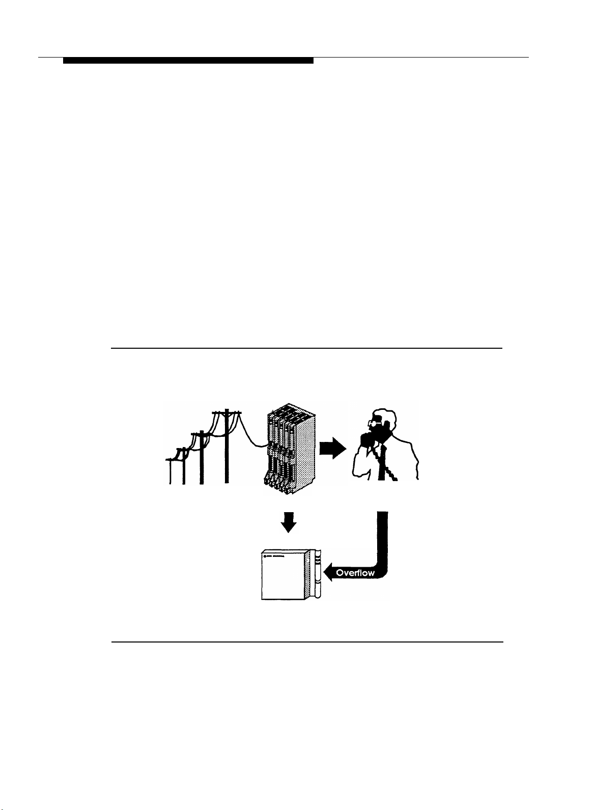
Delayed Call Handling
An outside call rings at the system extensions. If a system user does not answer the
call after the fourth ring, the PARTNER System sends the call to the Automated
Attendant service as shown in Figure 1-3. This delay allows any system user to
answer the call before the PARTNER System routes the call to the PARTNER MAIL
system.
PARTNER II
Control Unit
Central Office Lines
Answers call after fourth ring
PARTNER MAIL
Figure 1-3. PARTNER MAIL System as Delayed Call Handler
System User
System Services and Features
1-9
Page 24

Introduction
Voice Mail Service
The Voice Mail Service allows subscribers (people registered on the PARTNER
MAIL system) to perform these tasks:
■
Listen to messages.
■
Create a message and send it to one or more subscribers.
■
Receive a message and forward it to one or more subscribers, with additional
comments, if desired.
■
Record their own personal greeting and name.
■
Assign their own password, which they can change at any time to ensure that
messages are kept confidential.
■
Designate a subscriber to serve as their Personal Operator. The PARTNER
MAIL system connects callers to a Personal Operator if they press [ 0
personal greeting plays.
] after a
In addition, the Voice Mail Service allows the System Administrator to do the
following:
■
Create group lists to enable subscribers to send a single message to several
subscribers.
■
Use the Broadcast feature to send a single message to all subscribers.
■
Perform administration of the PARTNER MAIL system.
Subscriber's Mailbox
By default, the PARTNER MAIL system provides mailboxes for extensions 10
through 57. Users assigned to those extensions are PARTNER MAIL subscribers.
Except for the General Mailbox, a user’s extension number and mailbox number are
the same. When a caller leaves a message, the PARTNER MAIL system places the
message in the called subscriber’s mailbox, and turns ON the message light at the
subscriber’s system phone. Subscribers with the Outcalling feature can also have the
system call an off-site telephone, or beeper to inform the subscriber that a new
message has arrived in his or her mailbox. The Outcalling feature is described later
in this chapter.
1-10 System Services and Features
Page 25

Introduction
Call Answer Service
Call Answer Service provides three major features:
■
Extension Coverage
■
CO Line Coverage
■
Voice Mailbox Transfer
Call Answer Service is useful to employees who rely exclusively on the telephone,
are on the road during the day, or may be unavailable much of the time. With Call
Answer, potential clients can leave detailed messages in the employee’s mailbox.
The employee can retrieve the message at his or her convenience and get back to
the client. These features and two additional features are described below.
Extension Coverage
Extension coverage consists of the following:
■
Automatic VMS Cover which allows callers to leave messages or transfer to
another extension when the extension called is busy or does not answer, and
■
the VMS Cover button which enables users to turn VMS Cover ON and OFF
at their extension.
Automatic VMS Cover
When VMS cover is activated at the called extension, the system greets the caller
with the called party’s personal greeting or with the system greeting if a personal
greeting is not recorded. The caller may do one of the following:
■
Press [ 0 ] to transfer to the System Operator or the called party’s personal
operator.
■
Press [ ✱ ] [ 8 ] to transfer to another extension.
■
Record a message that the PARTNER MAIL system leaves in the called
party’s mailbox.
VMS Cover Button
Regardless of the Automatic VMS Cover setting, the PARTNER System enables
users to press a programmed button to turn Voice Mail Cover ON or OFF at an
extension. Users must program a button with lights on their system telephone (MLS-
34D, MLS-18D, MLS-12, MLS12D, MLS-6, MLC-6 model telephones) for this
purpose.
System Services and Features 1-11
Page 26

Introduction
CO Line Coverage
The PARTNER MAIL system provides two levels of line coverage if you do not want
to use PARTNER MAIL Automated Attendant service, or you want to provide
coverage for a private line.
CO Line Coverage consists of assigning VMS Line Cover to a line enabling callers
who call in on the covered line to leave messages in the General Mailbox if no
owner is assigned to the line and no one answers the call. To enhance this feature,
the System Administrator assigns PARTNER MAIL Line Ownership to specify a
subscriber's extension (mailbox) as the “owner” of the covered line. When a call
comes in on the covered line, the system routes the caller to the line owner’s
mailbox if the call is not answered. The caller has the option of leaving a message or
transferring to another extension.
Voice Mailbox Transfer
Users may program buttons on their system phones that allow them to transfer
callers directly to another subscriber’s voice mailbox without causing the phone to
ring at the subscriber’s extension. This feature is useful when handling a call for a
person who is not at his or her desk. You can transfer callers to the subscriber’s
voice mailbox where they can leave a message.
Outcalling
The Outcalling feature enables the PARTNER MAIL system to notify a subscriber at
a remote telephone, or activate the subscriber’s beeper, when a new message is in
the subscriber’s mailbox. Subscribers who have the Outcalling feature administered
to their mailbox, can remotely log on to PARTNER MAIL Voice Mail Service and
retreive the new message or turn Outcalling ON or OFF. They can also enter and
change their outcalling telephone, beeper or pager number using the Voice Mail
Service (see the previous section).
1-12 System Services and Features
Page 27

Installation
This chapter provides instructions for installing the PARTNER MAIL system and for
connecting it to the PARTNER II Communications System Release 3.
2
2-1
Page 28

Installation
Preparing for Installation
Verify that you have all the required PARTNER MAIL system and PARTNER II
Release 3 parts, and that the installation site meets the given environmental
conditions before beginning installation.
Parts Checklist
The AT&T PARTNER MAIL Voice Messaging System shipment should contain the
following parts:
PARTNER MAIL Unit
■
PARTNER MAIL Cabinet
■
Wall-mount and Cable Manager Bracket and screws
NOTE:
The cabinet and bracket are together referred to as the PARTNER
MAIL unit.
■
For a single voice-processing card configuration: two (2) 8-foot modular
telephone cords
For a dual voice-processing card configuration: four (4) 8-foot modular
telephone cords
■
PARTNER MAIL power cord
■
RMD (Remote Maintenance Device) cable
Remote Maintenance Device (shipped separately)
■
RMD
■
Modular telephone cord
■
RMD power cord
2-2 Preparing for Installation
Page 29

Installation
PARTNER II Release 3 Hardware Requirements
The following PARTNER II Release 3 equipment is required to install the PARTNER
MAIL system:
■
PARTNER II Release 3 Control Unit equipped with Processor Module
■
Release 2 206 Module
Preparing the Site
The PARTNER MAIL unit should be wall-mounted adjacent to the PARTNER II
System’s Control Unit, on the same mounting surface if possible.
WARNING:
If there is not sufficient room on the existing mounting surface, either secure a
new surface (a piece of plywood) or attach the PARTNER MAIL unit directly to
wall studs. This will best ensure permanent mounting and will prevent wall
damage.
To help ensure trouble-free operation, maintain the following environmental
conditions:
■
Dust-free area (preferably in an office environment)
■
Vibration free area
■
Relative humidity 8% to 85%
■
No exposure to liquids (avoid areas near drinking fountains, coffee makers,
and so on)
■
Recommended Temperature range: 60°F (15°C) to 80°F (26°C)
Maximum Temperature range: 40°F (4°C) to 104°F (40°C)
■
Adequte clearance around PARTNER MAIL unit
■
Do not place objects on top of the PARTNER MAIL unit
■
Do not block the PARTNER MAIL unit’s vents or openings
Preparing for Installation
2-3
Page 30

Installation
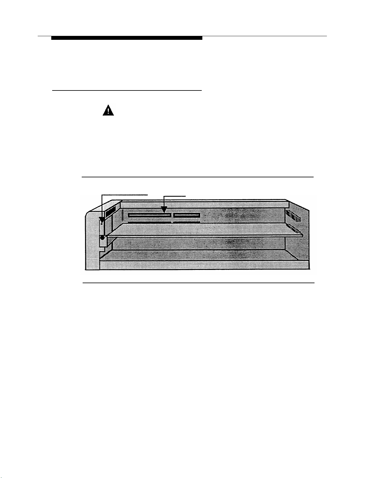
Installing the PARTNER MAIL Unit
Installation of the PARTNER MAIL unit (Figure 2-1) involves the following three
phases:
■
Mounting the unit on the wall near the PARTNER II Release 3 processor,
■ Connecting the unit to the PARTNER II Release 3 system,
■
Connecting the Remote Maintenance Device (modem) to the PARTNER MAIL
unit and to the PARTNER System.
Before you begin, be sure the installation site has been prepared properly.
Figure 2-1. PARTNER MAIL Unit
2-4 Installing the PARTNER MAIL Unit
Page 31

Installation
Mounting the PARTNER MAIL Unit
1.
Remove the bracket from the shipment package.
2.
Use the bracket as a template to mark the points on the wood surface where
you will insert the wall-mounting screws. Position the bracket on the surface
so that the slot is upward (Figure 2-2).
WARNING:
Be sure to install the wall-mounting screws in wall studs or in a piece of
plywood to ensure permanent mounting and to prevent wall damage.
Wall
Slot
Wood
Mounting
Surface
Wall Mount
and Cable
Manager
Bracket
Cable
Manager
Figure 2-2. Wall-Mounting the PARTNER MAIL Unit
3.
Secure the bracket onto the surface using the four #8 screws provided.
Installing the PARTNER MAIL Unit
2-5
Page 32
Installation
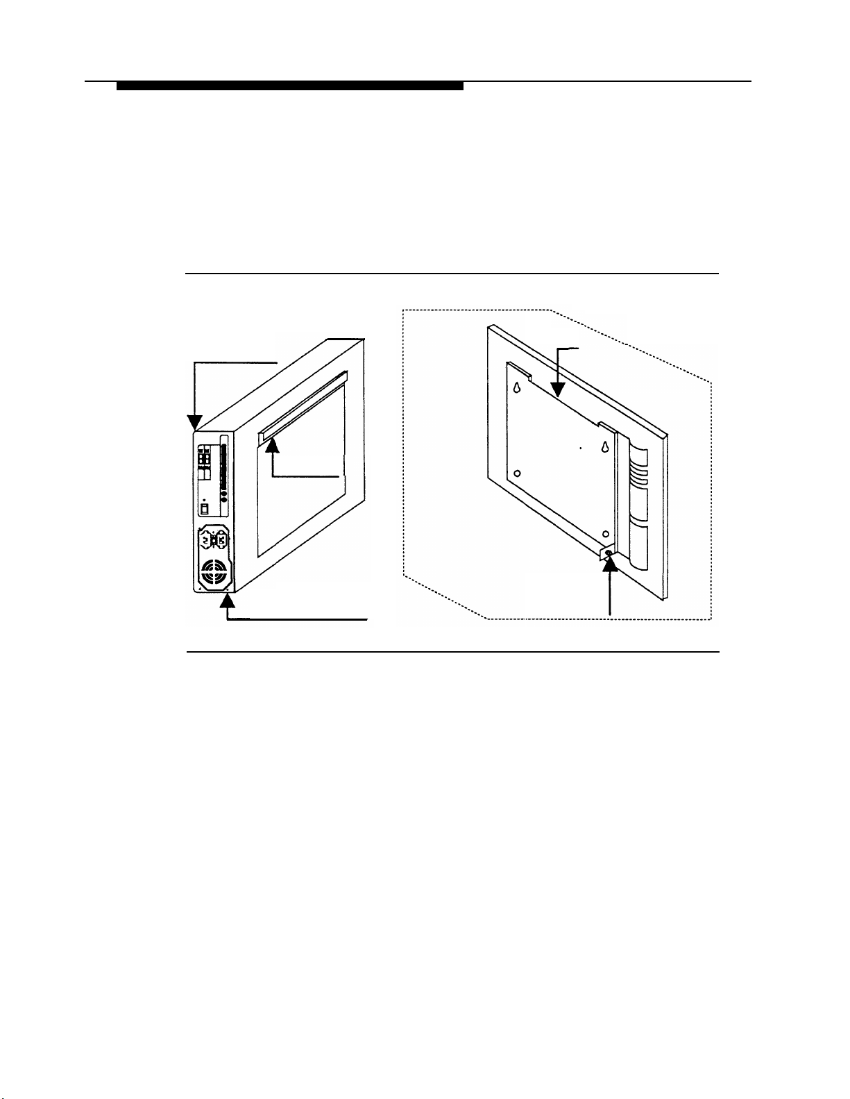
4.
Remove the #6-32 hex-head screw from the rear panel of the unit.
5.
Insert the PARTNER MAIL unit’s bracket lip into the bracket slot.
6.
Tighten the captive retaining screw into the mounting hole on the unit.
Wall
Slot
Rear panel
Bracket Lip
Remove screw from
mounting hole
Figure 2-3. Mounting the PARTNER MAIL Unit
Captive
Retaining
Screw
2-6 Installing the PARTNER MAIL Unit
Page 33

Installation
Connecting the Unit to the PARTNER II Release 3 System
1.
Route the line cords through the slots on the cable manager.
2.
Connect two (or four) modular telephone cords into the ports 1 — 2 or 1 — 4
on the PARTNER MAIL system.
Refer to PARTNER II Release 3 Planning Form B1, and locate the extension
3.
jack numbers for the PARTNER MAIL system cords.
NOTE:
Do not connect the PARTNER MAIL system cords to the top extension
jack of any 206 Module or to power failure transfer extensions 10, 16,
22, 28, 34, 40, 46, or 52.
NOTE:
For proper operation, do not connect the PARTNER MAIL system cords
to a PARTNER System Release 1 206 module (the 206 module Iabled
R1.0).
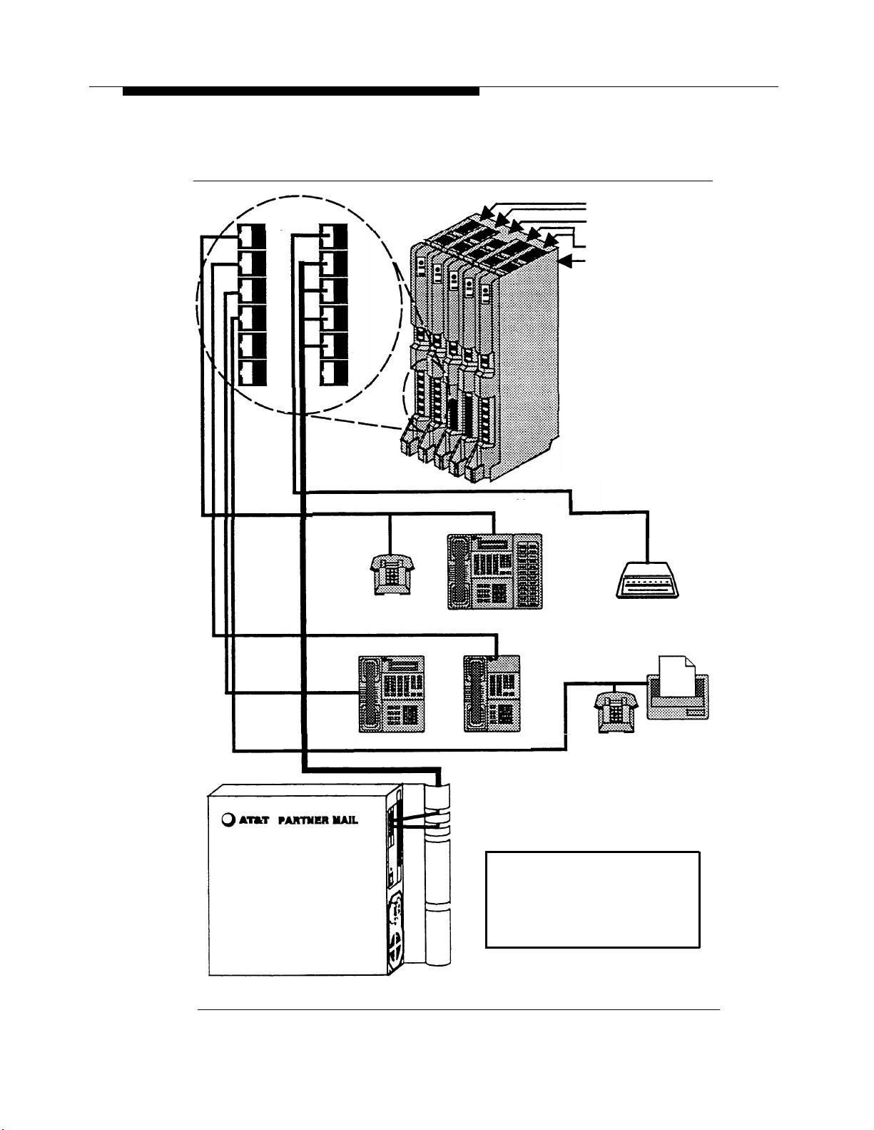
4.
Connect the other end of the modular telephone cords into extension jacks on
the PARTNER II Release 3 206 Module(s) (Figure 2-4).
NOTE:
Be sure to connect the cords from the lowest-numbered port to the
lowest-numbered jack and from the highest-numbered port to the
highest-numbered jack.
Installing the PARTNER MAIL Unit 2-7
Page 34
Installation
10
11
12
13
16
17
18
19
206 Modules
Primary Processor
Module (center slot)
400 Modules
Backplane
14
15
20
21
Extension 10
Extension 12 Extension 11
Extension 16
Extension 13
Figure 2-4. Connect PARTNER MAIL to PARTNER System
2-8 Installing the PARTNER MAIL Unit
Extensions
17, 18, 19, 20
Connections Shown are
for this example only.
Page 35
Installation
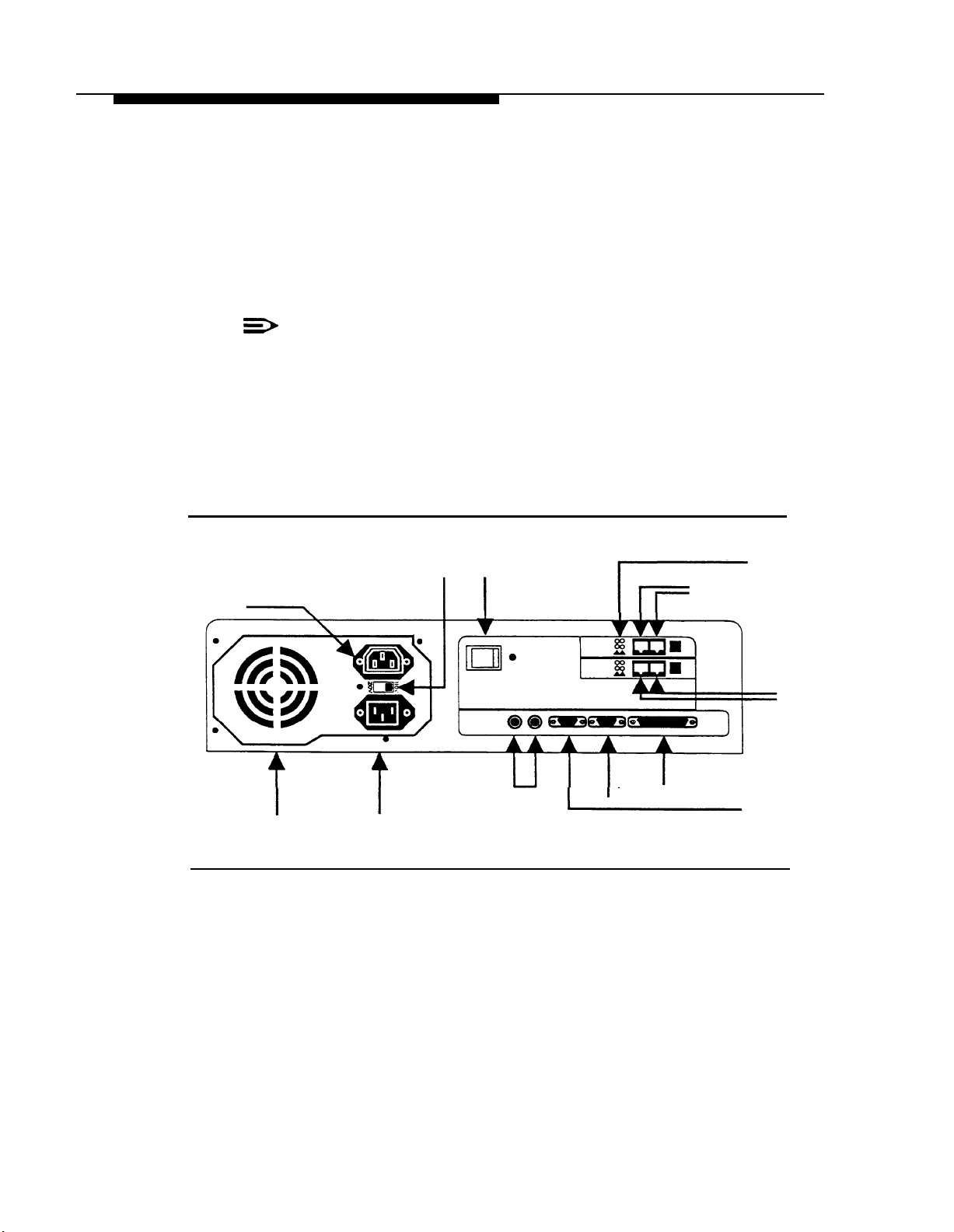
5.
Plug the power cord into the unit’s AC Power IN socket (Figure 2-5).
6.
Check the Voltage Selector Switch to ensure that it is set for your local power
source (Figure 2-5).
7.
Plug the power cord into a properly grounded AC electrical source.
NOTE:
It is strongly recommended that you connect the PARTNER MAIL unit
into the same electrical circuit as the PARTNER II Release 3 so that
the two units share a common ground.
8.
Turn the Power Switch ON (Figure 2-5).
9.
After 2-minutes all Status Indicator Lights should be green indicating that all
PARTNER MAIL system ports are ready to receive calls (Figure 2-5).
Not Used
Vent
(Do not block)
Voltage Selector
Switch (110V/230V)
AC Power IN Used
Power
Switch
Figure 2-5. PARTNER MAIL Unit - Rear Panel
Not
Status Indicator Lights
Port 4
Port 3
Not
Not
Used Used
(COM2)
Remote Maintenance
Device Connector (COM1)
Port 1
Port 2
Installing the PARTNER MAIL Unit
2-9
Page 36
Installation
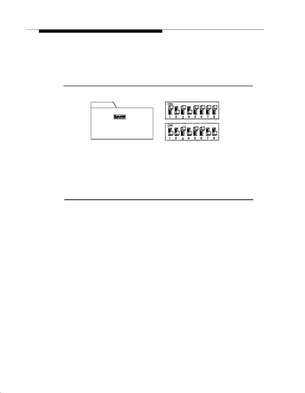
Connecting the Remote Maintenance Device to the Unit
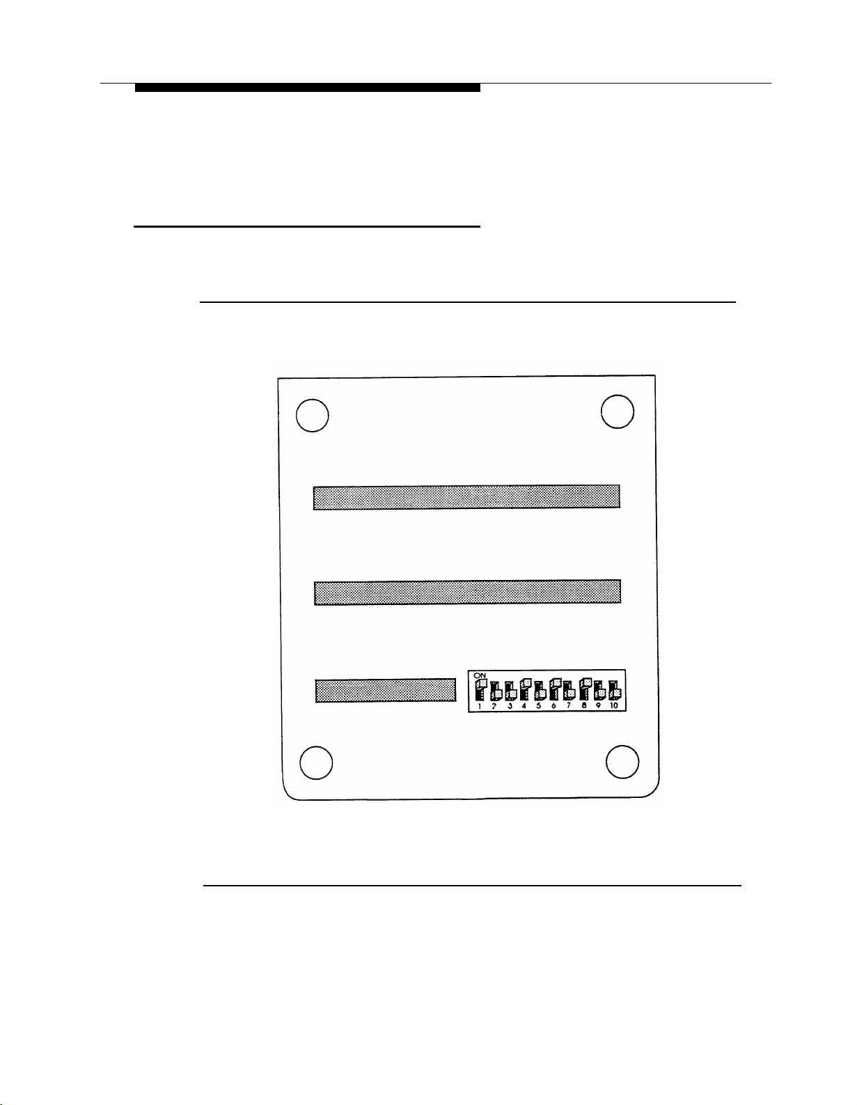
1.
The RMD switches are preset at the factory. Confirm that the switches,
located on the underside of the RMD, are set as shown in Figure 2-6.
Figure 2-6. PARTNER MAIL RMD Switch Settings
2-10 Installing the PARTNER MAIL Unit
Page 37
Installation
NOTE:
If you reset the switches, turn the RMD OFF and ON so that the new
settings take effect.
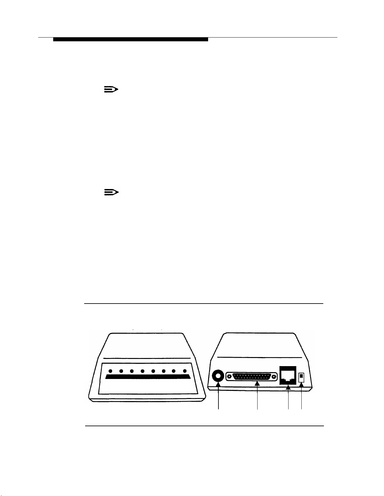
2.
Use the RMD cable to connect the RS-232-C port on the RMD to the COM1
port on the PARTNER MAIL unit (Figure 2-7).
3.
Refer to PARTNER II Planning Form B1 to determine the PARTNER II
extension jack for the RMD.
4.
Use the provided modular telephone cord to connect the RMD telephone line
port to the extension jack on the PARTNER II 206 Module (refer to
Figure 2-4).
NOTE:
Be sure to connect the cords from the lowest numbered port to the
lowest numbered jack, and from the highest numbered port to the
highest numbered jack.
5.
Attach the RMD Power Cord to the RMD (Figure 2-7).
Plug the power cord into a properly grounded AC electrical source.
6.
Turn the RMD ON (Figure 2-7).
7.
8.
The following red status lights are lit: HS, AA, TR, and MR.
9.
Write the 206 Module extension jack number which connects to the RMD onto
a label, and affix the label to the RMD for ongoing maintenance.
Remote Maintenance Device
(Front View)
Remote Maintenance Device
Power IN
Remote Maintenance Device
(Back View)
AC
RS 232-C
Telephone On/Off
Line Port
Switch
Figure 2-7. The PARTNER MAIL Remote Maintenance Device (modem)
Installing the PARTNER MAIL Unit
2-11
Page 38

Installation
Add or Replace Voice-Processing Card
NOTE:
After you have installed the voice processing card, ensure that the extensions
on the PARTNER System where you connect the new PARTNER MAIL
system ports, are administered to the VMS Hunt Group as described in
Chapter 3.
DANGER:
Only qualified personnel should replace the Voice Processing Cards. Personal
injury or damage to the cards may result if the cards are installed incorrectly.
Customers with a 2-port configuration may want to upgrade to a 4-port configuration
to support a greater volume of calls or an increased number of subscribers. To
upgrade from two to four ports, you need to add a voice-processing card.
Removing the PARTNER MAIL Unit
1. Turn the PARTNER MAIL unit OFF.
2.
Unplug the PARTNER MAIL system power cord.
DANGER:
The PARTNER MAIL unit must be unplugged before removing the
cover. Hazardous voltage is inside. Failure to comply could cause
electric shock.
Disconnect all modular telephone cords from the PARTNER MAIL unit.
3.
2-12 Add or Replace Voice-Processing Card
Page 39
Installation
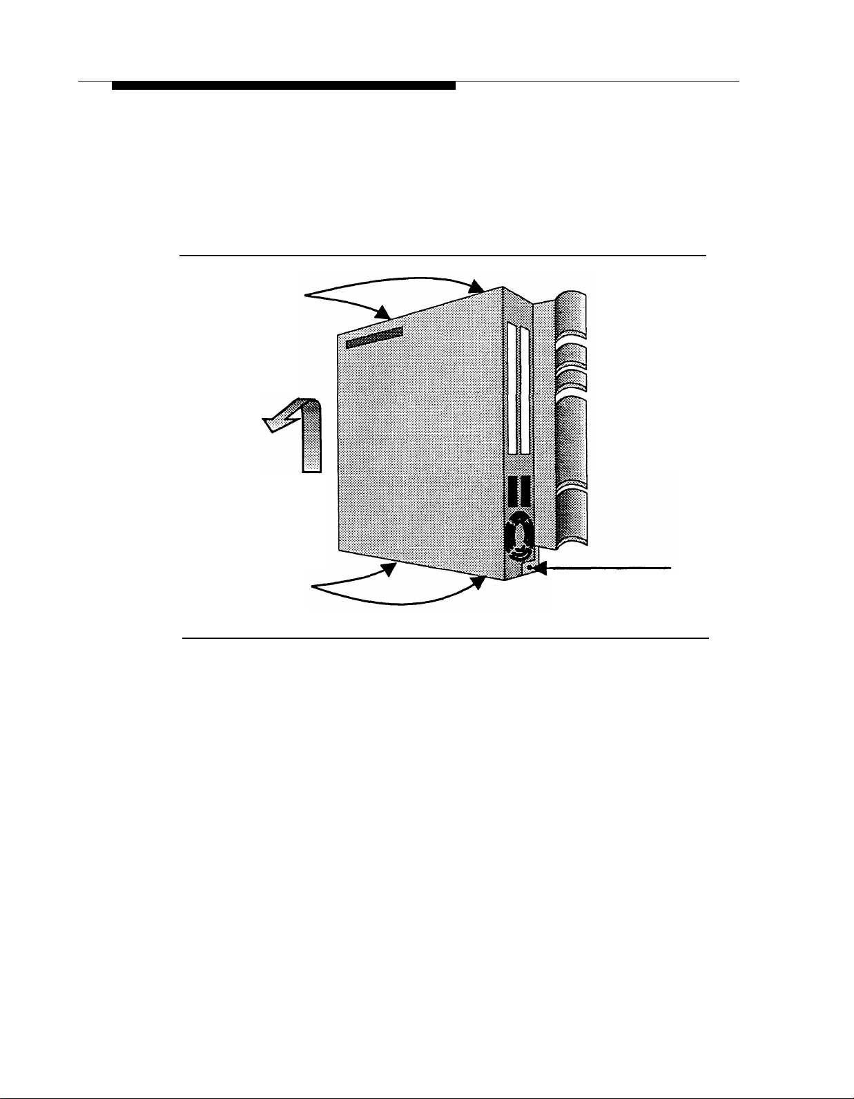
4.
Loosen the captive retaining screw (Figure 2-8).
5.
Carefully lift the unit up and out of the bracket, and place it on a sturdy flat
tabletop (Figure 2-8).
Cover screws
Lift up
and out
Cover screws
Figure 2-8. Remove Unit from Wall-mount
6.
Remove the four screws located on the right and left sides of the PARTNER
MAIL unit.
7.
Remove the cover.
Loosen retaining
screw
Add or Replace Voice-Processing Card
2-13
Page 40
Installation
Verifying Switch Setting
WARNING:
To avoid damaging any electrical component, wear a grounded Static
Wrist Band before handling PARTNER MAIL system circuitry.
1.
Remove the screw from the upper card slot (Figure 2-9).
Remove the clear plastic slot plate.
2.
Remove screw Socket
Figure 2-9. Remove Screw from Unit
2-14 Add or Replace Voice-Processing Card
Page 41
Installation
3.
Use Figure 2-10 to verify the switch settings on the voice-processing card
being installed.
Card 1: Ports 1 and 2
Dip Switch
Voice Processing Card
Card 2: Ports 3 and 4
Figure 2-10. Voice Processing Card Switch Settings
Add or Replace Voice-Processing Card
2-15
Page 42

Installation
Installing the Voice Processing Card
1.
Install the voice-processing card into the upper slot so that the connector of
the card fits securely into the female connector inside the PARTNER MAIL
unit (Figure 2-11).
2.
Install the plastic card spacer so that it holds the upper and lower cards at the
center of the unit, but does not touch any of the components on either card.
3.
Tighten the screw that holds the bracket on the left edge of the unit to secure
the upper card (Figure 2-11)
Tighten Screw
Figure 2-11. Installing a Voice Card
2-16 Add or Replace Voice-Processing Card
Page 43

Installation
4.
Replace the cover so that the latch fits under the front lip on the unit
(Figure 2-12).
Install and tighten the four cover screws.
5.
Latch
Front Lip
Figure 2-12. Installing the Cover
Add or Replace Voice-Processing Card
2-17
Page 44

Installation
Remounting the PARTNER MAIL Unit
1.
Mount the unit by inserting the PARTNER MAIL system bracket lip into the
bracket slot on the wall-mount (Figure 2-3, Figure 2-13).
PARTNER MAIL
Cabinet
Wall
Slot
Wood
Mounting
Surface
Retaining
PARTNER MAIL
Bracket
Mounting hole for
Captive Retaining Screw
Bracket
Figure 2-13. Mounting the PARTNER MAIL Unit
2.
Tighten the captive retaining screw on the wall mount.
3.
Refer to PARTNER II Release 3 Planning Form B1, and locate the extension
jack numbers for the PARTNER MAIL system modular cords.
Cable
Manager
Wall Mount
and Cable
Manager
Bracket
Captive
Retaining
Screw
2-18 Add or Replace Voice-Processing Card
Page 45

Installation
NOTE:
Do not connect the PARTNER MAIL system to the top extension jack of
any 206 Module or to power failure transfer extensions 10, 16, 22, 28,
34, 40, 46, or 52.
NOTE:
For proper operation, do not connect the PARTNER MAIL system cords
to a PARTNER System Release 1 206 module (the 206 module Iabled
R1.0).
NOTE:
Be sure to connect the cords from the lowest-numbered port to the
lowest-numbered jack and from the highest-numbered port to the
highest-numbered jack.
4.
Connect the modular telephone cords from the PARTNER MAIL system ports
to the PARTNER System extension jacks.
5.
Connect the power cord to the PARTNER MAIL unit.
6.
Plug the PARTNER MAIL system power cord into a properly grounded AC
source.
7.
Turn the PARTNER MAIL system power switch ON.
8.
If the PARTNER MAIL system and the PARTNER System have already been
programmed, perform the Acceptance Tests in Chapter 5.
Add or Replace Voice-Processing Card
2-19
Page 46

PARTNER II
System Programming
Use the procedures in this chapter to program the PARTNER II Release 3
Communications System so that it works with the PARTNER MAIL system as an
integrated unit. When the PARTNER System is installed, it uses factory settings that
reflect the most common usage of the equipment. You can change these settings as
required to customize them for the customer’s site.
3
You can program the PARTNER System from extension 10 or 11. Since an
extension cannot be in program mode and handle calls at the same time, and since
extension 10 is generally administered as the PARTNER MAIL System Operator's
extension, you may find it more convenient to program from extension 11 while the
receptionist continues to handle calls from extension 10.
System Programming changes settings for the system as a whole, or for individual
lines or extensions. You can also use System Programming to set up dialing
restrictions, define groups, or set up auxiliary equipment, (Refer to PARTNER
Communication System Release 3 Programming and Use for more information on
the various System Programming options). Refer to the completed PARTNER II
Release 3 System Planner when you are changing system settings, and be sure that
any changes in programming are recorded on the planning forms.
®
II
3-1
Page 47

PARTNER II System Programming
PARTNER II System Planning Forms
Before programming the PARTNER System, ask the PARTNER System Manager for
the following planning forms:
■
Form A: System Configuration
Records basic information about the customer’s business and the customer’s
AT&T sales representative or authorized dealer. The customer indicates the
line number and type of PARTNER MAIL system coverage required for each
line, and other settings required to program the PARTNER System for the
PARTNER MAIL system.
■
Form B1: System Lines
Records information for each system extension. This includes the type of
telephone or auxiliary equipment at the extension, the name of the system
user. or a description of how a specific extension is used.
■
Form B2: Customized Extension Settings
Records feature settings that apply to a specific extension or group of
extensions. This includes the creation of Hunt Groups, and the assignment of
features such as VMS Line Cover, and Auto Extension Privacy.
■
Form C: Telephone Button Programming Templates
Shows where to program features on system telephones (MLS-34D, MLS-
18D, MLS-12, MLS-6, MLC-6H model telephones).
3-2 PARTNER II System Planning Forms
Page 48

PARTNER II System Programming
Introduction to System Programming
System Programming requires a System Telephone (MLS-34D, MLS-18D, or MLS-
12D phone with a display) at extension 10 or 11, with a programming overlay placed
over the phone’s dialpad. System Programming procedures are identified by # and a
3-digit code (for example, the procedure used to program the System Date is #101).
You can program the system in one of two ways:
■
Direct Method: enables you to access a programming procedure directly by
dialing the code for that procedure. This method works best when you are
only using a few procedures during the programming session, and you know
the codes.
For example, press [ # ] [ 1 ] [ 0 ] [ 3 ] to change the system time.
■
Cycle Method: enables you to cycle through a sequence of procedures in
numerical order by pressing
this method when programming PARTNER II Release 3 for the first time, or
when you are changing a series of related settings. However, procedures
#399, #609, and #728 are skipped when you cycle through procedures
[
Next Procedure
]
or
[
Prev Procedure
].
You should use
NOTE:
You can talk on the telephone while you program. This is useful if you need to
talk to someone at the AT&T Helpline about programming. However, you must
place the call before you enter programming mode, and you must use the
handset to talk, not the speakerphone.
Introduction to System Programming
3-3
Page 49

PARTNER II System Programming
Using Programming Overlays
During System Programming, the normal functions of several buttons on the display
phone at extension 10 or 11 change. For example, the left
[ System Program ], which is the button used to enter programming mode. To identify
these buttons while programming, place the appropriate programming overlay
provided with the system on the dialpad of the phone at extension 10 or 11.
Use the following special buttons while programming:
[
Next Procedure
■
programming procedures. (Example: #101, #102, #103 ...)
■
[ Next Item ] and [ Prev Item ] cycle forward and backward through the parameters
offered by a procedure. (Example: Extension 10, 11, 12...)
■
[
Next Data
offered by a procedure. (Example: 1 Assigned, 2 Not Assigned)
■
[ Remove ] returns the current setting to the factory setting.
■
[ Enter ] indicates the end of a variable length entry, such as a telephone
number in the Allowed Phone Number List.
]
and
]
and
[
Prev Data
[ Intercom ] becomes
[
Prev Procedure
]
cycle forward and backward through data values
]
cycle forward and backward through the
■
[ System Program ] starts the System Programming process.
■
[ Central Tel Program ] starts the Central Telephone Programming process. This
enables you to program system telephones from extension 10 or 11.
■
[
Feature
]
when followed by [ 0 ] [ 0 ], enters and exits the programming mode.
Accessing System Programming
Before you can program any of the procedures in this chapter, you must access the
System Programming feature as follows:
At extension 10 or 11, press
1.
2.
Press
[
System Program
3.
Press
[
System Program
Now you can enter specific procedure numbers. Make sure the overlay is in place
over the system phone’s dialpad.
].
].
[
Feature
]
[ 0 ] [ 0 ].
3-4 Introduction to System Programming
Page 50

PARTNER II System Programming
Initial System Programming
Regardless of whether you are programming the PARTNER System to use
PARTNER MAIL Automated Attendant Service, Call Answer Service or both, you
must program the procedures outlined below. Completing these procedures enables
you to access the PARTNER MAIL hunt group and program the PARTNER MAIL
system.
After you complete the procedures below, refer to “Chapter 4 — PARTNER MAIL
Initial Programming” and perform all initial programming for the PARTNER MAIL
system. After completing the initial programming of the PARTNER MAIL system,
return to this chapter an complete PARTNER System programming for the
PARTNER MAIL Automated Attendant Service and Call Answer Service.
Assign VMS Ports Using Hunt Group Extensions (#505)
Use this procedure to assign all PARTNER MAIL system extensions (extension jacks
on the PARTNER System’s 206 Module where modular telephone cords from the
PARTNER MAIL system are connected) to VMS Hunt Group 7.
1.
Locate the two or four PARTNER MAIL system extensions on PARTNER II
Form B1.
2.
Access System Programming as described in “Accessing System
Programming” and press [ # ] [ 5 ] [ 0 ] [ 5 ].
Press [ 7 ] at the
3.
Group:
prompt
NOTE:
To avoid misoperation during a power loss, do not attach the
PARTNER MAIL system to the Power Failure Transfer extensions 10,
16, 22, 28, 34, 40, 46, and 52.
4.
Enter the PARTNER MAIL system EXTENSION at the Extension: prompt.
Press
[
5.
To program the next extension, press
6.
Next Data
]
until the display reads
1 Assigned
[
Next Item
]
or
[
Prev Item
]
until the
extension appears, then repeat step 5.
7.
Choose:
—
Press [ #
] and the system program number to program another feature,
or
—
—
[ Next Procedure ] to program another feature, or
Press
Press
[
Feature
]
[ 0 ] [ 0 ] to exit programming.
Initial System Programming 3-5
Page 51

PARTNER II System Programming
Assign the Transfer Return Extension (#306)
This procedure ensures that a call routed by the system to a user’s extension, that
does not answer and does not have coverage, is transferred to the System
Operator’s extension (normally extension 10). Assign a Transfer Return Extension for
each PARTNER MAIL system extension as described below.
1.
Locate the two or four PARTNER MAIL system extensions on PARTNER II
Form B1.
2.
Access System Programming as described in “Accessing System
Programming” and press [ # ] [ 3 ] [ 0 ] [ 6 ].
3.
Enter the first PARTNER MAIL system EXTENSION at the Trns Ret Ext
prompt.
4.
Enter the System Operator's
prompt.
EXTENSION
(normally [ 1 ] [ 0 ]) at the
Data
5.
To program another extension press [ Next Item ] or [ Prev Item ] until the extension
number appears on the display, then repeat step 4.
6.
Choose:
— Press [ #
—
Press
—
Press
] and a system program number to program another feature, or
[
Next Procedure
[
Feature
]
]
or
[
Prev Procedure
[ 0 ] [ 0 ] to exit programming.
Program the PARTNER II System for the RMD
Use the following procedures to remove all lines from the RMD (Remote
Maintenance Device), and to assign Automatic Extension Privacy to the RMD.
Remove Lines Using Line Assignment (#301)
1.
Refer to PARTNER II Form B1 to determine the RMD extension, and refer to
PARTNER II Form B2 to determine the customized extension settings for the
RMD.
2.
Access System Programming as described in “Accessing System
Programming” and press [ # ] [ 3 ] [ 0 ] [ 1 ].
]
to program another feature, or
3.
Enter the RMD EXTENSION at the Extension: prompt.
Press
[
Remove
4.
]
3-6 Initial System Programming
to remove all existing line assignments.
Page 52

PARTNER II System Programming
5.
Choose:
—
—
—
Press [ #
Press
Press
] and a system program number to program another feature, or
[
Next Procedure
[
Feature
]
]
or
[
Prev Procedure
[ 0 ] [ 0 ] to exit programming.
Assign Automatic Extension Privacy (#304) to the RMD
Use the procedure below to assign Automatic Extension Privacy to the RMD
extension so that users on the same line cannot interrupt RMD transmissions.
1.
Refer to PARTNER II Form B1 to identify the RMD extension.
2.
Access System Programming as described in “Accessing System
Programming” and press [ # ] [ 3 ] [ 0 ] [ 4 ].
3.
Enter the RMD EXTENSION at the Extension: prompt.
4.
Press
[
5.
Choose:
—
—
—
Next Data
Press [ #
Press
Press
]
until the display reads:
1 Assigned.
] and a system program number to program another feature, or
[
Next Procedure
[
Feature
]
]
or
[
Prev Procedure
[ 0 ] [ 0 ] to exit programming.
]
to program another feature, or
]
to program another feature, or
At this point, go to “Chapter 4 — PARTNER MAIL Initial Programming" and perform
all initial programming for the PARTNER MAIL system. After completing the initial
programming, return to this chapter and complete the following as indicated on the
PARTNER II Release 3 System Planning forms:
■
Automated Attendant Service
■
Call Answer Service
■
Telephone Buttons
Initial System Programming
3-7
Page 53

PARTNER II System Programming
Programming Automated Attendant
This section presents the procedures required to program the PARTNER II Release
3 for use with PARTNER MAIL Automated Attendant Service.
Assign VMS Hunt Delay (#506)
Set the delay for either Immediate or Delayed Call Handling.
1.
Locate “VMS Hunt Delay” on PARTNER II Form A.
2.
Access System Programming as described in “Accessing System
Programming” and press [ # ] [ 5 ] [ 0 ] [ 6 ].
If “Immediate Call Handling” is checked (the factory setting for Automated
3.
Attendant Service) press
[
Next Data
]
until the display reads:
1 Immediate.
If “Delayed Call Handling” is checked press [ Next Data ] until the display reads:
4.
2 Delayed.
5.
Choose:
— Press [ #
—
Press
—
Press
] and a system program number to program another feature, or
[
Next Procedure
[
Feature
]
]
or
[ 0 ] [ 0 ] to exit programming.
Assign the VMS Hunt Schedule (#507)
Specify when the Automated Attendant Service handles calls.
1.
Locate “VMS Hunt Schedule” on PARTNER II Form A.
Access System Programming as described in “Accessing System
2.
Programming” and press [ # ] [ 5 ] [ 0 ] [ 7 ].
3
If:
the customer checked “Always” (the factory setting), press
—
until
1 Always
the customer checked “Day only”, press
—
displayed.
is displayed.
[
Prev Procedure
]
to program another feature, or
[ Next Data ]
[
Next Data
]
until
2 Day Only
is
the customer checked “Night only”, press
—
Only
is displayed.
3-8 Programming Automated Attendant
[ Next Data ] until 3 Night
Page 54

PARTNER II System Programming
4.
Choose:
— Press [ # ] and a system program number to program another feature, or
—
—
[ Next Procedure ] or [ Prev Procedure ] to program another feature, or
Press
Press
[
Feature
]
[ 0 ] [ 0 ] to exit programming.
Assign Group Call Distribution (#206)
Assign outside lines, which are to be answered and provided PARTNER MAIL
Automated Attendant service, to the VMS Hunt Group 7.
1.
Locate Lines on PARTNER II Form A which have “VMS-AA” written in the
“Line Coverage” column.
2.
Access System Programming as described in “Accessing System
Programming” and press [ # ] [ 2 ] [ 0 ] [ 6 ].
Press [ 7 ] at the
3.
4.
Enter a two-digit Line number at the Line: prompt.
Press
[
5.
To program another line, press [ Next Item ] or [ Prev Item ] then repeat the
6.
Next Data
previous step.
7.
Choose:
— Press [ # ] and a system program number to program another feature, or
Group:
]
until
1 Assigned
prompt,
is displayed.
Press
[
—
—
Press
Next Procedure
[
Feature
Programming Fax Extensions
If using the Automated Attendant Service to handle fax calls, refer to the PARTNER
II Release 3 Programming and Use document for the procedures required to
program the PARTNER II to recognize your fax extensions or groups.
]
or
[
Prev Procedure
]
[ 0 ] [ 0 ] to exit programming.
]
Programming Automated Attendant
to program another feature, or
®
3-9
Page 55

PARTNER II System Programming
Programming Call Answer Service
This section presents the forms and procedures required to program the PARTNER
II Release 3 for use with PARTNER MAIL Call Answer Service. This includes
Extension and CO Line coverage.
Automatic VMS Cover (#310)
Review PARTNER II Form B2 to determine which users require the Automatic VMS
Cover feature. This feature determines if an extension is normally covered by the
Call Answer Service. This means that an unanswered intercom or transferred call
goes to PARTNER MAIL for Call Answer Service. Assign Automatic VMS Cover to
the extensions listed on Form B2 as described below:
1.
Access System Programming as described in “Accessing System
Programming” and press [ # ] [ 3 ] [ 1 ] [ 0 ].
Enter the EXTENSION at the Extension: prompt.
2.
Press
[
3.
To program another extension, press
4.
Next Data
]
until the display reads
Assigned.
[
Next Item
]
or
[
Prev Item
]
until the
extension number appears on the display, then repeat step 3.
5.
Choose:
— Press [ # ] and a system program number to program another feature, or
Press
[
—
—
Press
Next Procedure
[
Feature
]
]
or
[
Prev Procedure
]
to program another feature, or
[ 0 ] [ 0 ] to exit programming.
NOTE:
Refer to “Telephone Button Programming” found at the end of this chapter to
program a VMS Cover button to enable subscribers to turn VMS Cover ON
and OFF at their extensions.
3-10 Programming Call Answer Service
Page 56

PARTNER II System Programming
CO Line Coverage
Use the Group Call Distribution (#206) procedure to assign outside lines to the VMS
Line Cover option. PARTNER MAIL answers calls on these lines after four rings. If a
Line Owner is assigned (see note below), PARTNER MAIL transfers the caller to the
Line Owner’s mailbox. If there is no Line Owner assigned, PARNTER MAIL transfers
the caller to the General Mailbox. Callers at remote sites may also use Group Call
Distribution to access PARTNER MAIL if the Automated Attendant Service is not in
operation by pressing [ ✱ ] [ 7 ] when the PARTNER MAIL system answers.
1.
Locate Lines on PARTNER II Form A which have “VMS-MAIL” written in the
“Line Coverage” column.
2.
Access System Programming as described in “Accessing System
Programming” and press [ # ] [ 2 ] [ 0 ] [ 6 ].
3.
Press [ 7 ] at the
4.
Enter a two-digit Line number at the Line: prompt.
Group:
prompt,
5.
Press
[
Next Data
To program another line, press [ Next Item ] or [ Prev Item ] the line number
6.
]
until
3 VMS Line Cover
is displayed.
appears on the display, then repeat the previous step.
7.
Choose:
— Press [ # ] and a system program number to program another feature, or
Press
[
—
—
Press
Next Procedure
[
Feature
]
]
or
[
Prev Procedure
]
to program another feature, or
[ 0 ] [ 0 ] to exit programming.
NOTE:
To assign Line Ownership, perform the PARTNER MAIL Line Ownership
procedure in Chapter 4 of this guide.
Programming Call Answer Service
3-11
Page 57

PARTNER II System Programming
Programming Night Service (#503)
Use the procedure below to assign a Night Service Button onto the MLS-model
system phone at the System Operator's extension. Keep the following mind:
■
You can only program a Night Service button on extension 10.
■
You can only program a Night Service button on an MLS-model system
phone.
■
You must program Night Service on a button with lights.
■
Refer to “Night Service Button (#503)” in PARTNER
System Release 3 Programming and Use for details on how to set up Night
Service.
1.
Locate the “NightSVC” label on PARTNER II Form C (the button programming
template).
®
II Communications
2.
Access System Programming as described in “Accessing System
Programming” and press [ # ] [ 5 ] [ 0 ] [ 3 ].
3.
Choose:
— To assign Night Service to the first available button on the system
phone, press
Night Service
1 Assigned-Ext10
[
Next Data
]
until the display reads:
— To assign Night Service to a specific button, press [ 3 ]. The display
reads:
Night Service
3 Select Button
4.
Press the progammable button with lights indicated on Form C.
5.
Choose:
—
Press [ #
—
Press
—
Press
6.
Label the Night Service button at extension 10.
] and a system program number to program another feature, or
[
Next Procedure
[
Feature
]
]
or
[
Prev Procedure
]
to program another feature, or
[ 0 ] [ 0 ] to exit programming.
3-12 Programming Night Service (#503)
Page 58

PARTNER II System Programming
Telephone Button Programming
PARTNER II Form C provides button templates for each type of MLS and MLC
telephone. We recommend that you program a button on each subscriber's system
telephone for the following features:
■
VMS Cover
■
Voice Mailbox Transfer
■
Auto Dial into PARTNER MAIL
The procedures below utilize Centeral Telephone Programming.
VMS Cover Button (F15)
To give subscribers the ability to turn Voice Mail coverage ON and OFF, you may
program a VMS Cover button at the subscriber’s system phone as described below:
1.
Locate the “VMSCover” label on PARTNER II Form C (the button
programming template).
2.
Press
[
Feature
]
[ 0 ] [ 0 ]
3.
Enter the EXTENSION for the system telephone being programmed.
4.
Press a programmable button with lights.
Press
[
Feature
]
5.
Program another button for this extension or press
6.
[ 1 ] [ 5 ]
[
System Program
] [
System Program
] [
Central Tel Program
[
Feature
programming mode.
]
[ 0 ] [ 0 ] to exit
].
Telephone Button Programming
3-13
Page 59

PARTNER II System Programming
Programming Voice Mailbox (F14)
The Voice Mailbox Transfer feature enables the System Operator, or any system
user, to transfer calls directly to the called party’s mailbox, without ringing the
extension. If, for example, a caller wants to talk to a subscriber who is on vacation,
the receptionist can transfer the call to the subscriber's mailbox by pressing the
Voice Mailbox button followed by the called party’s extension. PARTNER MAIL would
answer the call using the called party’s greeting (if he or she recorded a greeting),
and the caller could then leave a message for the called party.
1.
Locate the “VMBox” label on PARTNER II Form C (the button programming
template).
Press
[
Feature
]
2.
Enter the EXTENSION of the system telephone being programmed.
3.
4.
Press a programmable button.
[ 0 ] [ 0 ]
[
System Program
] [
System Program
] [
Central Tel Program
].
Press
[
Feature
]
5.
Program another button for this extension or press
6.
[ 1 ] [ 4 ].
programming mode.
Programming Auto Dial into PARTNER MAIL
To provide one-touch dialing into PARTNER MAIL, program an Auto Dial button for
all subscribers either at the subscribers’ system telephones or through Centralized
Telephone Programming.
Locate the “VMS” label on PARTNER II Form C (the button programming
1.
template).
Press
[
Feature
]
2.
Enter the EXTENSION of the system telephone being programmed.
3.
Press a programmable button.
4.
[ Intercom ] [ 7 ] [ 7 ] [ 7 ] (the Partner Mail Hunt Group).
Press
5.
Program another button for this extension or press
6.
[ 0 ] [ 0 ]
programming mode.
[
System Program
] [
System Program
[
Feature
]
[ 0 ] [ 0 ] to exit
] [
Central Tel Program
[
Feature
]
[ 0 ] [ 0 ] to exit
].
3-14 Telephone Button Programming
Page 60

PARTNER MAIL Initial Programming
This chapter provides guidelines and procedures for initial programming of the
PARTNER MAIL system. The terms program and administer are used interchangably
throughout this guide.
4
4-1
Page 61

PARTNER MAIL - Initial Programming
Introduction to Programming
PARTNER MAIL system programming is performed by placing a call to the
PARTNER MAIL system and logging in as the System Administrator. The System
Administrator uses the dialpad on a touch-tone phone to program the PARTNER
MAIL system. The PARTNER MAIL system plays voice prompts in response to the
touch-tones that you press on the dialpad.
Only the System Administrator may program the PARTNER MAIL system by
accessing the “hidden” option 9 from the Voice Mail Menu.
PARTNER MAIL System Programming Menus
Figure 4-1 illustrates the menus available from the Administration Main Menu. You
must access the PARTNER MAIL system Administration Main Menu before
administering any of the seven submenus listed in Figure 4-1. Refer to the
Administration Map inside the front cover of this guide for a complete listing of all
PARTNER MAIL system administration menus and submenus.
4-2 Introduction to Programming
Page 62

PARTNER MAIL - Initial Programming
Enter System Administrator Extension + #
Enter System Administrator Password + #
Voice Mail Service
Voice Mail
Menu
9
Administration
Main Menu
System
Parameters
1
Schedule
Automated
Attendant
3
Mailboxes
2
Group
Lists
4
Figure 4-1. PARTNER MAIL System Programming Menus
5
Line
Ownership
System
Greetings
7
6
Introduction to Programming
4-3
Page 63

PARTNER MAIL - Initial Programming
Accessing the Administration Main Menu
Use the following procedure to access the PARTNER MAIL system Administration
Main menu.
1.
Press
[
Intercom
2.
Enter the System Administrator's
[ # ].
3.
Enter the System Administrator’s
[ # ].
— The system plays the seven items on the the Voice Mail Menu
(Figure 4-1).
— The system does not play menu item 9, the Administration Menu. The
System Administrator is the only subscriber who can select the “hidden”
menu option 9 from the Voice Mail Menu.
]
[ 7 ] [ 7 ] [ 7 ] or a preprogrammed button.
MAlLBOX
PASSWORD
(initially [ 9 ] [ 9 ] [ 9 ] [ 7 ]) and press
(initially [ 1 ] [ 2 ] [ 3 ] [ 4 ]) and press
4.
Press [ 9 ] to program.
The system plays the system programming options.
Refer to Appendix A for a list of all factory settings. You should confirm a factory
setting, as instructed, even if you are not changing the setting.
Programming Hints
■
You do not need to wait for a prompt before proceeding to the next step if you
are experienced with PARTNER MAIL system programming.
■
Press [ ✱ ] [ # ] to return to the previous menu.
■
Press [ ✱ ] [ 4 ] to repeat the current menu options.
■
Press [ ✱ ] [ 7 ] to return to the System Administration Menu.
■
Press [ ✱ ] [ ✱ ] [ 9 ] to exit from the PARTNER MAIL system.
■
To avoid background noise, speak into the handset to record names,
greetings, and announcements instead of using the speakerphone.
4-4 Introduction to Programming
Page 64

PARTNER MAIL - Initial Programming
Before Programming
Before you program the PARTNER MAIL system, ensure that the programming and
planning tasks described below are completed.
PARTNER II Programming
A technician must program the PARTNER II Communications System for the
PARTNER MAIL system as described below before you program the PARTNER
MAIL system:
■
Assign all PARTNER MAIL system extensions to Hunt Group 7.
■
Assign the Transfer Return Extension for the PARTNER MAIL system
extensions.
Refer to “Chapter 3 — PARTNER II System Programming" for instructions.
Planning Forms
Obtain completed copies of all PARTNER II and PARTNER MAIL system planning
forms.
Planning forms provide the names, extensions, mailboxes and other information
required to complete the PARTNER MAIL system administration.
PARTNER MAIL System Planning Forms
Obtain completed copies of the following forms from the PARTNER MAIL System
Administrator
■
Form 1: Mailbox Assignments
■
Form 2: System Parameters
■
Form 3: Voice Mail Greeting
■
Form 4: Automated Attendant Settings
■
Form 5: Automated Attendant Day Greeting and Menu
■
Form 6: Automated Attendant Night Greeting and Menu
■
Form 7: Automated Attendant Submenus
■
Form 8: Automated Attendant Announcements.
■
Form 9: Group Lists
■
Form 10: Line Ownership
Before Programming
4-5
Page 65

PARTNER MAIL - Initial Programming
PARTNER II Planning Forms
Obtain completed copies of the following forms from the PARTNER II System
Manager
■
Form A: System Configuration
■
Form B1: System Extensions
■
Form B2: Customized Extension Settings
■
Form C: Button Programming Templates
4-6 Before Programming
Page 66

PARTNER MAIL - Initial Programming
Programming System Parameters
Program the PARTNER MAIL System Parameters (Figure 4-2) regardless of the
services used.
Administration
Main Menu
System
Parameters
1
FAX
Extension
System
Operator
4
Extension
5
General
Mailbox
Owner
6 7
System
Administrator
Mailbox
Figure 4-2. Programming PARTNER MAIL System Parameters
FAX
Message
Receiver
8
Programming System Parameters
4-7
Page 67

PARTNER MAIL - Initial Programming
Assigning the
System Administrator Mailbox
■
Refer to PARTNER MAIL Form 2: System Parameters to locate the desired
mailbox number.
■
Factory Setting: 9997
Change the factory setting for System Administrator’s mailbox to
prevent unauthorized programming of the PARTNER MAIL system.
1.
Access the Administration Main Menu as described in an earlier section.
PARTNER MAIL plays the system programming options.
2.
Press [ 1 ] to program System Parameters.
3.
Press [
7
] to change the System Administrator Mailbox.
The current mailbox number plays.
4.
Choose:
—
To change the System Administrator Mailbox dial the new MAlLBOX
followed by [ # ].
The system confirms the new System Administrator mailbox number.
From now on, the System Administrator logs on to the system using
this mailbox number.
To keep the current mailbox press [ # ].
—
✱
5.
Press [
] [ # ] to return to the Administration Main Menu.
4-8 Programming System Parameters
Page 68

PARTNER MAIL - Initial Programming
Changing the System Administrator’s
Password
■
Factory Setting: 1234.
Change the factory settings for System Administrator’s password to
prevent unauthorized programming of the system.
NOTE:
If the System Administrator changes the password and forgets it, or a new
System Administrator does not know the password set by his or her
predecessor, contact the AT&T Helpline or an authorized AT&T dealer to reset
the password after obtaining proper authorization from the customer. The
AT&T Helpline phone number is listed on the inside cover of this guide.
1.
Press
[
Intercom
]
[ 7 ] [ 7 ] [ 7 ] or a preprogrammed button.
2.
Enter the System Administrator’s
MAlLBOX
(initially [ 9 ] [ 9 ] [ 9 ] [ 7 ]) and press
[ # ].
3.
Enter the System Administrator’s
PASSWORD
(initially [ 1 ] [ 2 ] [ 3 ] [ 4 ]) and press
[ # ].
The Voice Mail Menu plays.
Press [ 5 ] to program your new password.
4.
The prompt asks you to enter your new password.
5.
Enter your
PASSWORD
followed by [ # ].
The prompt asks you to re-enter your new password.
6.
Enter your
PASSWORD
followed by [ # ].
The new password is now active.
Press [ ✱ ] [ # ] to return to the Voice Mail Menu, then press [ 9 ] to access the
7.
Administration Main Menu or hang up to quit.
Programming System Parameters
4-9
Page 69

PARTNER MAIL - Initial Programming
Assigning the System Operator’s Extension
The system transfers calls to the System Operator’s extension if callers receiving the
Automated Attendant service enter [ 0
Timeout Option to transfer calls to the System Operator.
■
Use Form 2: System Parameters to locate the System Operator’s extension.
■
Factory Setting: 10
Keep the factory setting unless a new setting is desired.
1.
Access the Administration Main Menu as described in an earlier section.
The system plays the system programming options.
2.
Press [ 1 ] to program System Parameters.
5
3.
Press [
] to program the System Operator extension.
The current extension plays.
] or take no action, and you set the Dial 0 /
4.
5.
Choose:
— To change the System Operator’s extension: Enter the new
EXTENSION
followed by [ # ].
The new extension is confirmed.
To keep the factory setting of 10: press [ # ].
—
✱
Press [
] [ # ] to return to the Administration Main Menu.
4-10 Programming System Parameters
Page 70

PARTNER MAIL - Initial Programming
Assigning a General Mailbox Owner
If the Dial 0 / Timeout Options are set for the General Mailbox, the system transfers
callers to the General Mailbox extension if they enter [ 0
■
Use Form 2: System Parameters to determine the General Mailbox Owner’s
extension.
■
Factory Settings:
Extension: 10
—
Mailbox number: 9999 (Cannot be changed)
—
Password: 1234.
—
■
The General Mailbox owner must log in as mailbox 9999 to retrieve messages
from the GeneraI Mailbox and to change the General Mailbox Owner’s
password.
] or take no action.
■
To change the General Mailbox password, perform the following:
Log on using mailbox 9999.
—
— Use the same procedure as shown for “Changing the System
Administrator Password”.
1.
Access the Administration Main Menu as described in an earlier section.
The system plays the system programming options.
2.
Press [ 1 ] to program System Parameters.
6
3.
Press [
] to program the General Mailbox.
The current extension plays.
4.
Choose:
To change the General Mailbox Owner’s extension: Enter the new
—
EXTENSION
followed by [ # ].
The new extension is confirmed.
To keep the factory setting of 10: press [ # ].
—
✱
5.
Press [
] [ # ] to return to the Administration Main Menu.
Programming System Parameters 4-11
Page 71

PARTNER MAIL - Initial Programming
Programming the Fax Extension
Assign the Fax extension, or the Fax Hunt Group, where the Automated Attendant
Service transfers fax calls.
■
Use Form 2: System Parameters to identify the fax extension or Fax Hunt
Group.
■
When you program the system to transfer fax messages, the Touch-Tone
Gate is set ON automatically. This enables the system to immediately detect
fax transmissions and send them to a fax machine.
1.
Access the Administration Main Menu as described in an earlier section.
The system plays the system programming options.
Press [ 1 ] to program System Parameters.
2.
4
3.
Press [
] to program the fax extension.
Enter the Fax extension or Fax Hunt Group extension followed by [ # ]. The
4.
system confirms the new fax extension and plays,
The touch-tone gate is on.
NOTE:
To deactivate fax call handling, enter [ 0
] as the fax extension, then
press [ # ].
✱
5.
Press [
] [ # ] to return to the System Administration Menu.
4-12 Programming System Parameters
Page 72

PARTNER MAIL - Initial Programming
Assigning the Fax Message Receiver
Designate the mailbox where the system leaves a prerecorded message after it
receives a fax transmission. The system lights the Message light on the subscriber’s
system telephone indicating that a message is stored.
■
Use Form 2: System Parameters to identify the extension for the Fax
Message Receiver.
■
There is no factory setting. If you do not assign a Fax Message Receiver, the
system does not light the Message Iight at any extension after it receives a
fax transmission.
■
PARTNER II Release 3 cannot light Message lights on single line telephones.
Only assign the Fax Message Receiver to system telephones to allow use of
the Message light.
1.
Access the Administration Main Menu as described in an earlier section.
The system plays the system programming options.
2.
Press [ 9 ] to program.
3.
Press [ 1 ] to program System Parameters.
8
Press [
4.
5.
Enter the EXTENSION of the new Fax Message Receiver followed by [ # ].
Press [ ✱ ] [ # ] to return to the System Administration Menu.
6.
] to program the Fax Message Receiver.
Programming System Parameters
4-13
Page 73
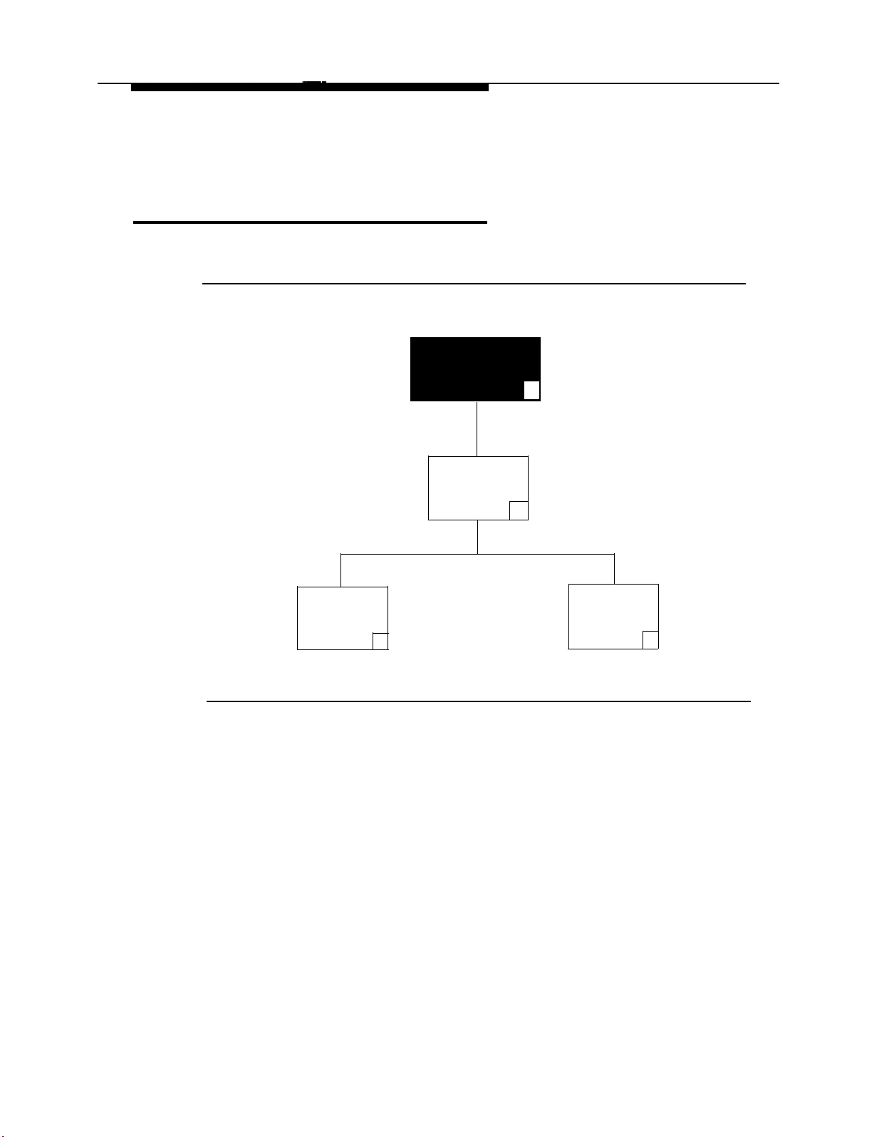
PARTNER MAIL - Initial Programming
Programming the Schedule
Figure 4-3 illustrates the options available when programming the schedule.
Administration
Main Menu
9
Schedule
Update
System Date
and Time
1
Figure 4-3. Programming the Schedule
2
Open or
Closed
for Today
3
4-14 Programming the Schedule
Page 74

PARTNER MAIL - Initial Programming
Setting the Date and Time
Synchronize the date and time settings on the PARTNER MAIL system to those on
the PARTNER II Release 3 system.
1.
Access the Administration Main Menu as described in an earlier section.
The system plays the system programming options.
2.
Press [ 2 ] to program the Schedule.
3.
Press [
The system plays the current date, and prompts you to enter a new date.
4.
To accept the date played, press [ #
following:
The system confirms the date.
5.
Press [ 1 ] to reenter the date or press [ ✱ ] [ # ] to accept the date.
1
] to program date and time.
]. To enter a new date (mmddyy) enter the
— mm: 01-12
— dd: 01-31
—
yy: 00-99
Example: for May 28, 1993 press:
[ 0 ][ 5 ], [ 2 ][ 8 ], [ 9 ][ 3 ]
1
If you pressed [
—
If you pressed [ ✱ ] [ # ]:
—
The system plays the current time and prompts you to enter a new
time.
], go to step 4.
Programming the Schedule 4-15
Page 75

PARTNER MAIL - Initial Programming
To accept the time played, press [ # ]. To enter a new time (hhmm) enter the
6.
following:
— hh: 00–23
— mm: 00-59
The system confirms the new time.
NOTE:
If requested, enter [ 1
enter A.M. or P.M. when the hour you enter is less than 13.
7.
Press [ 1 ] to reenter or press [ ✱ ] [ # ] to accept the time.
— If you pressed [ 1 ], go to step 6.
If you pressed [ ✱ ] [ # ]:
—
The system confirms the new time.
Press [ ✱ ] [ # ] to return to the System Administration Menu.
8.
] for A.M. or [ 2 ] for P.M. the system prompts you to
4-16 Programming the Schedule
Page 76

PARTNER MAIL - Initial Programming
Program Automated Attendant Menus
The Day or Night Main Menu offers the caller a list of options. Figure 4-4 shows the
Administration options required to program the Automated Attendant service menus.
Administration
Main Menu
Automated
Attendant
Service
9
3
Day
Menu
1
Figure 4-4. Automated Attendant
Each option is assigned a one-digit Selector Code and a corresponding Selector
Code Action. For example, the Main Menu for the ANY Travel Agency offers these
options:
For cruises, press [ 1
For corporate travel, press [ 2
For personal travel, press [ 3
For discounted trip information, press [ 4
announcement.
If you know the extension of the person you are calling, press
[ 5 ]
and enter that person’s extension.
Or press
The caller presses a key on the dialpad (a Selector Code), and the system performs
one of the corresponding Selector Code Actions Iisted below:
[ 0 ]
Night Submenus Announce-
Menu
2
].
].
].
for operator assistance.
3
ments
4
]
to hear a recorded
Touch-Tone
Gate
5
Program Automated Attendant Menus
4-17
Page 77

PARTNER MAIL - Initial Programming
■
Action 1 — Selector Code Transfer
When a caller presses the Selector Code, the system transfers the call to the
specific extension, Hunt Group, or Calling Group that you assign to the
Selector Code. For example, when callers to ANY Travel press [ 1
connects them to the cruise travel agent’s extension.
■
Action 2 — Play an Existing Submenu
When a caller presses the Selector Code, the system plays another menu
from which the caller presses another Selector Code. When callers to ANY
Travel press [ 2
], for example, the system plays the Corporate Travel submenu.
The submenu must already exist before you can program this action.
■
Action 3 — Play an Existing Announcement
When a caller presses the Selector Code, the system plays a prerecorded
announcement. Use this Action to provide information such as your business
hours or a mailing address. When callers to ANY Travel press [ 4
announcement regarding discounted trip information. The announcement must
already exist before you can program this action.
■
Action 4 — Prompted Transfer
When callers press the Selector Code, the system prompts them to enter an
extension. For example: ANY Travel uses extensions 10 through 40 in their
dial plan. They use Selector Codes 1 through 4 to direct callers to submenus
and announcements. To enable callers to enter extensions from the main
menu, ANY Travel assigns Prompted Transfer to Selector Code 5. Callers at
ANY Travel press [ 5
] at the main menu and enter an extension number.
], the system
] they hear an
■
Action 5 ✔ — Direct Extension Transfer
This is the factory setting for Selector Codes 1 through 5 on the Day and
Night Main Menus. Callers can enter an extension directly from the menu. For
example, if extensions 1 and 2 are used in the dial plan (indicating that all of
your extensions begin with 1 or 2) leave Selector Codes 1 and 2 at the
factory-setting. This enables callers to enter extension numbers without having
to enter another number first (see Action 4 above).
Program all announcements and lowest level submenus before programming higher
level submenus and the Automated Attendant Main Menus. Use this list to organize
your programming:
■
Program and record all announcements first.
■
Create the submenus, starting with the lowest-level submenu and continuing
up the submenu levels.
■
Program and record the Day Main Menu.
■
Program and record the Night Main Menu.
4-18 Program Automated Attendant Menus
Page 78

PARTNER MAIL - Initial Programming
■
Reorganize the Planning Forms as follows:
—
Form 8: Automated Attendant Announcements
— Form 7: Automated Attendant Submenus
— Form 6: Automated Attendant Night Main Menu
— Form 5: Automated Attendant Day Main Menu.
Creating Announcements
■
Refer to Form 8: Automated Attendant Announcements to program and record
an announcement.
■
Announcements may be up to 2 minutes long.
■
You may record up to 99 announcements. The announcement that you record
plays if callers press the corresponding Selector Code from the Day or Night
Menu or a submenu.
■
Tell callers to press [ ✱ ] [ # ] to back up to the previous menu, or to press [ ✱ ] [ 4 ]
to repeat the announcement.
■
Create announcements before programming the corresponding Selector Code.
■
To eliminate background noise, speak into the handset to record the
announcemnet.
1.
Access the Administration Main Menu as described in an earlier section.
The system plays the system programming options.
2.
Press [ 3 ] for Automated Attendant.
3.
Press [
4.
Press [
5.
Enter the announcement number (01 through 99) followed by [ # ].
6.
Choose:
4
] to program an announcement.
7
] to record an announcement.
[ 9 ] for “Yes” (confirm).
—
— [ 6 ] for “No” (cancel). Go back to step 5.
7.
Lift the handset and record the announcement.
Press [ 1 ] after recording the announcement.
8.
Program Automated Attendant Menus 4-19
Page 79

PARTNER MAIL - Initial Programming
9.
Choose an option:
Press [ 2 ] [ 1 ] to re-record the announcement.
—
Press [ 2 ] [ 3 ] to play back the announcement.
—
Press [ ✱ ] [ 3 ] to delete the announcement.
—
Press [ ✱ ] [ # ] to approve the announcement.
—
10.
Press [ ✱ ] [ # ] to return to the Administration Main Menu.
Creating Submenus
■
Refer to Form 7: Automated Attendant Submenus which contains the
Submenu Definition Table (submenu number, Selector Code, and Selector
Code Action information), and the submenu script.
■
You can create up to 99 submenus, but more than three menu levels tend to
confuse callers.
■
If you are creating more than one submenu, create the lowest-level submenu
first.
■
To eliminate background noise, speak into the handset while recording the
submenu prompt.
1.
Access the Administration Main Menu as described in an earlier section.
The system plays the system programming options.
2.
Press [ 3 ] for Automated Attendant.
3.
Press [
4.
Press [
5.
Enter the submenu number (01 through 99) followed by [
6.
Enter the Selector Code [ 1 ] through [ 9 ].
7.
Press the Selector Code Action.
3
] to program the submenu.
4
] to create a submenu.
[ 1 ] = Selector code transfer
—
—[ 2
] = Play a submenu.
#
].
—
[ 3 ] = Play an announcement.
—[ 4
] = Prompted transfer. Go to Step 9.
—[ 5
] = Direct extension transfer. Go to Step 9.
4-20 Program Automated Attendant Menus
Page 80

PARTNER MAIL - Initial Programming
8.
Enter the extension, submenu, or announcement number where the system
transfers callers, followed by [ # ].
NOTE:
You must create the submenu or announcement before creating the
submenu that directs callers to select the submenu or announcement.
Repeat Steps 6, 7, and 8 for each Selector Code. When finished, go to Step
9.
10.
10.
Press [ ✱ ] [ # ] to approve. The prompt asks you to record the submenu script:
Record at the tone.
11.
Lift the handset and record the submenu script.
12.
Press [ 1 ] after recording the submenu script.
13.
Choose an option:
Press [ 2 ] [ 1 ] to re-record the submenu;
—
Press [ 2 ] [ 3 ] to play back the submenu script;
—
—
Press [ ✱ ] [ 3 ] to delete the submenu script;
—
Press [ ✱ ] [ # ] to approve the submenu. The prompt says,
Approved. Menu Saved.
14.
Press [ ✱ ] [ # ] to return to the Administration Main Menu.
Program Automated Attendant Menus 4-21
Page 81

PARTNER MAIL - Initial Programming
Modifying the Day and Night Main Menus
■
Refer to Form 5: Automated Attendant Day Greeting and Menu.
■
Refer to Form 6: Automated Attendant Night Greeting and Menu.
■
Factory Settings: Selector Codes 1 through 5 are set for Selector Code Action
5 — Direct Extension Transfer. Selector codes 6 through 9 are unassigned.
This enables callers to enter extensions 10 through 57 directly after reaching
the Automated Attendant service.
NOTE:
Submenus and announcements must be created before the Main
Menus. Refer to the preceding instructions for “Creating Submenus”
and “Creating Announcements.”
■
To eliminate background noise, speak into the handset to record menu
prompts.
1.
Access the Administration Main Menu as described in an earlier section.
The system plays the system programming options.
2.
Press [ 3 ] for Automated Attendant
3.
Choose:
—
Press [ 1 ] to program the Day Main Menu.
—
Press [ 2 ] to program the Night Main Menu.
4.
Press [
5.
Enter the Selector Code [
6
] to modify the Main Menu.
1
] through [ 9 ].
The system plays the current Selector Code Action for the Selector Code.
6.
Press [ 9
] to confirm that you are modifying this Selector Code.
4-22 Program Automated Attendant Menus
Page 82

PARTNER MAIL - Initial Programming
Press the Selector Code Action.
7.
NOTE:
If you do not intend to use Selector Codes 1–5, instead of a
Selector Code Action enter [ ✱ ] [ 3 ] to set them to “not used.”
—[ 1
] Selector code transfer.
[ 2 ] Play a submenu
—
—
[ 3 ] Play an announcement
—
[ 4 ] Prompted transfer. Go to Step 9.
—[ 5
] Direct extension transfer. Go to Step 9.
8.
Enter the extension, submenu number, or announcement number where the
Automated Attendant transfers callers, followed by [ # ].
Repeat from Steps 5, 6, and 7 for each Selector Code on the Main Menu. Go
9.
to step 9 after you enter all Selector Codes.
10.
Press [ ✱ ] [ # ] to approve the Selector Codes.
The system plays the current Dial 0/Timeout Option, followed by the Dial
0/Timeout Option Menu.
The Dial 0 / Timeout Options specify where the system transfers calls if callers
enter [ 0 ] or do nothing.
11.
Choose the Dial 0/Timeout Action Option:
Press [ 0 ] for System Operator.
—
—
Press [ 1 ] for General Mailbox.
—
Press [ 2 ] to disconnect.
The Dial 0/Timeout Action Option is confirmed, and the prompt asks
you to record the entire Main Menu script.
Lift the handset and record the Main Menu script.
12.
Press [ 1 ] after recording.
13.
14. Choose an option or go to Step 15:
—
Press [ 2 ] [ 1 ] to re-record the Main Menu.
—
Press [ 2 ] [ 3 ] to play back the Main Menu.
—
Press [ ✱ ] [ 3 ] to delete the Main Menu and use the previously recorded
Main Menu.
Program Automated Attendant Menus
4-23
Page 83

PARTNER MAIL - Initial Programming
15.
Press [ ✱ ] [ # ] to approve the Main Menu.
The prompt says,
Approved. Menu Saved.
16.
Press [ ✱ ] [ # ] to return to the Administration Main Menu.
Setting the Touch-Tone Gate
When the Touch-Tone Gate is ON the Automated Attendant Greetings should
instruct callers to press [ 1
he or she hears the Automated Attendant menu. If the caller does not press [ 1
system transfers the call depending upon the Dial 0 / Timeout Option.
When the Touch-Tone gate is OFF, the Day or Night Greeting the system
immediately plays the corresponding menu. The system transfers callers for
assistance who do not enter a touch-tone after the menu prompt plays three times.
] if calling from a touch-tone phone. If the caller presses [ 1 ],
], The
When the Touch-Tone gate is ON, rotary callers do not have to listen to the Day or
Night Menu before being transferred for assistance.
■
Use Form 4: Automated Attendant Settings to identify the Touch-Tone Gate
setting.
■
Factory Setting: OFF.
■
If using Fax Call Handling, the Touch-Tone gate is automatically set to ON
and cannot be turned OFF.
1.
Access the Administration Main Menu as described in an earlier section.
The system plays the system programming options.
2.
Press [ 3
Press [ 5 ] to program the Touch-Tone Gate.
3.
4.
Choose:
] to program the Automated Attendant
— Press [ 9 ] to turn ON the Touch-Tone Gate. (This menu option only
plays when the Touch-Tone Gate is OFF).
—
Press [ 6
] to turn OFF the Touch-Tone Gate. (This menu option only
plays when the Touch-Tone Gate is ON.)
Press [ ✱ ] [ # ] to return to the System Administrator's menu.
5.
4-24 Program Automated Attendant Menus
Page 84
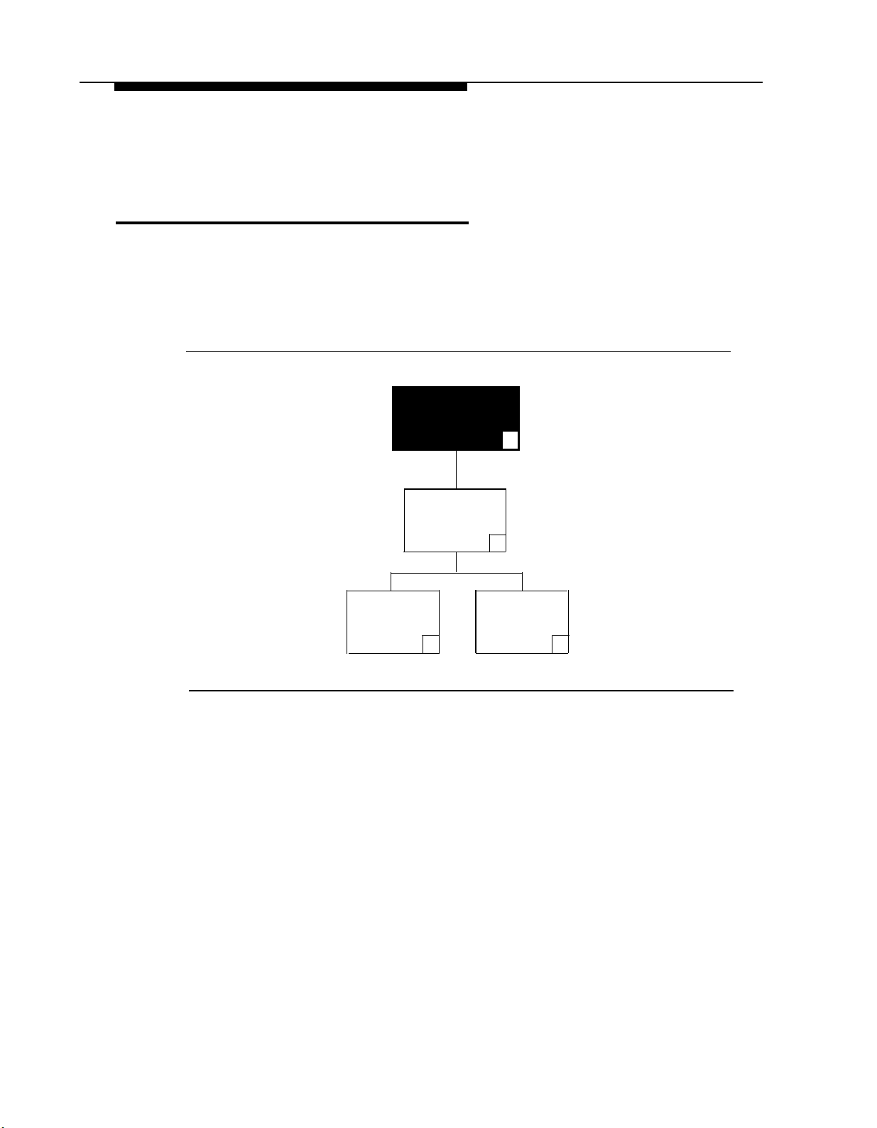
PARTNER MAIL - Initial Programming
Programming System Greetings
The Automated Attendant enables callers to reach destinations without human
assistance. When the Automated Attendant first answers a call, it plays a Day or
Night greeting, then a Day or Night menu.
Figure 4-5 illustrates the menus for recording system greetings.
Administration
Main Menu
9
Voice Mail
Greeting
Figure 4-5. System Greetings
System
Greetings
7
Automated
Attendant
1 3
Greeting
Programming System Greetings
4-25
Page 85

PARTNER MAIL - Initial Programming
Recording a Voice Mail Greeting
The Voice Mail Greeting plays when a subscriber calls the Voice Mail Service.
NOTE:
It is strongly recommended that you do not change this greeting.
■
Refer to Form 3: Voice Mail Greeting for the Voice Mail Greeting script.
■
Factory Setting:
Welcome to PARTNER MAIL. Please enter extension and pound sign.
■
To eliminate background noise while recording, use the handset instead of the
speakerphone when recording greetings.
1.
Access the Administration Main Menu as described in an earlier section.
The system plays the system programming options.
2.
Press [ 7
3.
Press [ 1
4.
Press [ 1
5.
Lift the handset and record the greeting (up to 10 seconds). The system
] to program the System Greetings.
] for Voice Mail Greeting.
] to record the greeting.
plays,
Record at the tone
Press [ 1 ] after recording the greeting.
6.
7.
Choose an option:
—
Press [ 2 ] [ 1 ] to re-record the greeting.
—
Press [ 2 ] [ 3 ] to play back the greeting.
—
Press [ ✱ ] [ 3 ] to delete the new greeting and use the current greeting.
—
Press [ ✱ ] [ # ] to approve the greeting.
Press [ ✱ ] [ # ] to return to the System Administration Menu.
8.
4-26 Programming System Greetings
Page 86

PARTNER MAIL - Initial Programming
Recording the Day and Night Greetings
■
Refer to Form 5: Automated Attendant Day Greeting and Menu and/or Form
6: Automated Attendant Night Greeting and Menu, for the scripts for the Day
and Night Greetings.
■
Record the Day Greeting (Form 5) first.
■
Record the Night Greeting (Form 6) second.
■
Each greeting must be 10 seconds or less.
■
To avoid background noise in your recording, use the handset instead of the
speakerphone when recording greetings.
■
Remember to record a prompt in the greeting if the Touch-Tone Gate is ON.
(See “Setting the Touch-Tone Gate” in a previous section of this chapter)
1.
Access the Administration Main Menu as described in an earlier section.
The system plays the system programming options.
Press [ 7 ] to program the System Greetings.
2.
3.
Press [
4.
Choose the appropriate option:
Press [
5.
6.
Lift the handset and record the greeting (up to ten seconds).
Press [ 1 ] after recording the greeting.
7.
8.
Select one of the following options:
Press [ ✱ ] [ # ] to return to the System Administration Menu.
9.
3
] for the Automated Attendant Greetings.
Press [ 1 ] for the Day Greeting.
—
—
Press [ 2 ] for the Night Greeting.
1
] to record the greeting.
Press [ 2 ] [ 1 ] to re-record the greeting.
—
Press [ 2 ] [ 3 ] to play back the greeting.
—
—
Press [ ✱ ] [ 3 ] to delete new the greeting and use the current greeting.
—
Press [ ✱ ] [ # ] to approve the greeting.
Programming System Greetings 4-27
Page 87

PARTNER MAIL - Initial Programming
Modifying Mailboxes
Administration
Main Menu
Mailboxes
4
Play Mailbox
Configuration
2
Figure 4-6. Programming Mailboxes
The PARTNER MAIL system is shipped with mailboxes created for extensions
10 through 57. The COS (Class of Service) describes the characteristics of
the mailbox. Review the Class of Service key and the guidelines which follow.
Create a
Mailbox
4
Delete a Modify a
Mailbox Mailbox
3
✱
6
4-28 Modifying Mailboxes
Page 88

PARTNER MAIL - Initial Programming
COS Key
Class Mins.
1
5
2 ✔ 10
3 15
4 5
5 10
6 15
7 15
8 15
9 60
■
Mins. (Minutes) (10 ✔ ) — the size of the mailbox.
■
Transfer Type —
—
Transfer Permitted ✔ : The system attempts to transfer the call to
Transfer Outcalling
Permitted
Permitted
Permitted
Not Permitted
Not Permitted
Not Permitted
Permitted Permitted
Permitted
Permitted
Not Permitted
Not Permitted
Not Permitted
Permitted
Permitted
Not Permitted
Permitted
Not Permitted
the extension entered by the caller.
—
Transfer Not Permitted: The system does not attempt to transfer
the call to the extension entered by the caller. Instead, the
system transfers the caller directly to the extension’s voice
mailbox.
■
Outcalling (Not Permitted ✔ ) — if permitted, and the subscriber
administers outcalling using the Voice Mail Service, the system calls a
designated telephone or pager whenever a new message is left in the
subscriber’s mailbox.
This section contains instructions for entering each subscriber into the PARTNER
MAIL system directory, and for recording each subscriber’s name. See Figure 4-6
for an oveview of the menus used to program Mailboxes. (To create or delete
Mailboxes, refer to the Chapter 6 — System Administration).
■
Obtain Form 1: Mailbox Assignments, which lists the names of subscribers,
their extension numbers, and COS (if it is different from the factory setting of
2).
■
Factory Setting: 2
■
A total of 100 Mailboxes can be created, but a maximum of 40 (for four port
systems) or 20 (for two port systems) is recommended to avoid trafficking
problems.
Modifying Mailboxes
4-29
Page 89

PARTNER MAIL - Initial Programming
■
To eliminate background noise, use the handset when recording mailbox
names.
■
You can assign Guest Mailboxes for users who do not have their own
extensions, but still require mailboxes. Assign a COS of 7, 8, or 9 to an
unused extension from 10 through 57. Assign the first Guest Mailbox to the
highest numbered extension available (e.g., extension 57) and work
backwards toward extension 10 to assign additional Guest Mailboxes. The
PARTNER MAIL system does not attempt to transfer callers receiving
Automated Attendant Service to the extension associated with the Guest
Mailbox. Instead, it transfers callers directly to the Guest Mailbox where they
can leave a message. Guests may log on and retrieve messages from any
touch-tone phone.
1.
Access the Administration Main Menu as described in an earlier section.
The system plays the system programming options.
Press [ 4 ] to program Mailboxes.
2.
6
3.
4.
Press [
Enter
] to modify a Mailbox.
EXTENSION
of mailbox being modified and press [ # ]. You can press [ # ]
to program each subsequent mailbox.
If the subscriber's name is not being modified, go to step 11.
5.
Press [ 1 ] to modify the name.
6.
Use Form A to enter first 4 characters of subscriber’s first or last name and
7.
[ # ].
Press [ 9 ] to confirm or press [ 6 ] to cancel the name.
8.
Lift the handset and record the subscriber’s name after the prompt.
9.
10.
Choose:
—
Press [ 2 ] [ 3 ] to play back, or
—
Press [ 2 ] [ 1 ] to re-record, or
—
Press [ ✱ ] [ 3 ] to delete, or
—
Press [ ✱ ] [ # ] to approve the name.
Press [ 2 ] to change the COS, or go to step 13.
11.
Use the COS Key shown on the previous page as a reference to enter the
12.
COS for the mailbox and [ # ].
When finished programming the first mailbox, press [
13.
through 13 as applicable for each subscriber.
Press [ ✱ ] [ # ] to return to the Administration Main Menu.
14.
4-30 Modifying Mailboxes
✱
] [ # ] and repeat steps 4
Page 90

PARTNER MAIL - Initial Programming
Creating Group Lists
Create Group Lists to send messages to groups of users. Refer to Figure 4-7 to
review the Group Lists programming options.
Administration
Main Menu
9
Group
Lists
5
Scan Group
Lists
Create a
Group List
2
4
Modify or
Review a
Group List
6
Delete a
Group List
Figure 4-7. Group Lists
■
Obtain Form 9: Group Lists, which shows the group’s name and Group List
Number, and lists the names and extensions of group members.
■
Up to 99 Group Lists can be created.
■
Make copies of Form 9 and distribute them to all group members.
1. Access the Administration Main Menu as described in an earlier section.
The system plays the system programming options.
Press [ 5 ] to program Group Lists.
2.
3.
Press [ 4 ] to create a Group List.
4.
Enter a Group List Number followed by [ # ].
5.
Enter the first member’s
EXTENSION
followed by [ # ].
The system plays: the subscriber's name (if previously recorded) or their
extension, and prompts you to enter the next extension number.
3
*
Enter the other members’
6.
EXTENSIONS
each followed by [ # ].
Creating Group Lists 4-31
Page 91

PARTNER MAIL - Initial Programming
When finished entering all extension numbers, press [ ✱ ] [ # ] to approve the list.
7.
8.
Press [ ✱ ] [ # ] to return to the System Administration menu.
4-32 Creating Group Lists
Page 92

PARTNER MAIL - Initial Programming
Assigning Line Ownership
Use the programming procedure below to associate an outside line with an extension
(mailbox) used to store messages for covered lines.
Refer to Figure 4-8 to review the Line Ownership programming options.
Administration
Main Menu
9
Line
Ownership
6
Scan Line
Ownership
2
Deallocate
Line
Ownership
✱
Assign Line
Ownership
3
4
Figure 4-8. Line Ownership
■
Refer to Form 10: Line Ownership to determine the Line number(s) that
requires coverage, and the Line Owner’s name and extension.
■
If an owner is not assigned to a covered line, the system transfers callers,
who call in on that line, to the General Mailbox.
1.
Access the Administration Main Menu as described in an earlier section.
The system plays the system programming options.
Press [ 6 ] to program Line Ownership.
2.
Modify Line
Ownership
6
4
Press [
3.
4.
Refer to Form 10 to enter a line number (1 to 24) followed by [ # ].
5.
Refer to Form 10 to enter the Line Owner’s EXTENSION followed by [ #
] to assign Line Ownership.
The system plays the Owner’s name (or the owner’s extension number if their
name was not previously recorded).
Assigning Line Ownership
].
4-33
Page 93

PARTNER MAIL - Initial Programming
6.
Repeat steps 4 and 5 until you assign line ownership to all lines. When
finished entering the lines, press [ ✱ ] [ # ] to return to the Administration Main
Menu.
This concludes the initial programming of the PARTNER MAIL system. Refer to
Chapter 3 — Partner II System Programming to complete the programming
procedures for the PARTNER II Communications System.
4-34 Assigning Line Ownership
Page 94

Verifying System Operation
Once you have completed the initial programming of the PARTNER MAIL system
and the PARTNER II Release 3 System, perform the Acceptance Tests to verify
proper operation.
5
5-1
Page 95

Verifying System Operation
Automated Attendant Service
If the VMS Hunt Schedule is set for day only, ensure that the Night Service button is
OFF. If the VMS Hunt Schedule is set for night only, ensure that the Night Service
button is ON.
Immediate Answer
1.
Call in on a line answered by the Automated Attendant.
2. Listen for the Automated Attendant Greeting. The call should be answered
after 2 rings.
3.
Repeat this test for each line programmed to be answered by the Automated
Attendant.
Delayed Answer
1.
Call in on a line assigned to the Automated Attendant. (Ask the primary call
handler not to answer the call.)
2.
Listen for the Automated Attendant Greeting. The Automated Attendant
service should answer the call after four rings.
3.
Repeat this test for each line programmed to be answered by the Automated
Attendant.
Day Main Menu
1.
Call in on a line programmed for Automated Attendant.
Press [ 1 ] if prompted by the Touch-Tone Gate.
2.
3. After the greeting, choose a Selector Code offered on the Day Menu.
4.
Ensure that your call is transfered to the appropriate extension, or that the
appropriate announcement, or submenu is played.
5.
Repeat this test for each Selector Code offered on the Day Menu.
5-2 Automated Attendant Service
Page 96

Verifying System Operation
Fax Call Handling
1.
Send a fax on one of the incoming lines assigned to Automated Attendant.
2.
Make sure that the fax is received by the fax machine.
3.
If a Fax Message Receiver has been programmed (see PARTNER MAIL
Form 2: System Parameters), check that the message light at the system
phone at the Fax Message Receiver extension is ON.
Night Menu
1.
Turn Night Service ON at extension 10.
2.
Place a call on an incoming line answered by the Automated Attendant.
3.
Listen for the Night Greeting followed by the Night Menu.
4.
Choose a Selector Code from the Night Menu.
5.
Make sure that the transfer is made to the appropriate extension, or that the
appropriate announcement, or submenu is played.
6.
Repeat this test for each Selector Code on the Night Menu.
Automated Attendant Service
5-3
Page 97

Verifying System Operation
Call Answer Service
Extension Coverage
Call an extension which has VMS Cover turned ON.
1.
Do not answer the called extension.
2.
After three rings the Call Answer Service answers, (after approximately 5
3.
rings) you should hear the Call Answer Greeting (or the subscriber’s personal
message).
Repeat this procedure for every extension that has VMS coverage.
4.
CO Line Coverage
1.
Call in on a Line assigned to the VMS Line coverage option.
2.
Do not answer the called Line.
3.
After 5 ringas, the Call Answer Service answers and you should hear one of
the following:
— If the line has an “Owner”, the owner’s greeting should prompt you to
— If the line does not have an owner, the prompt should tell the you to
4.
Repeat this procedure for every line assigned to the VMS Line coverage
option.
leave a message in his or her mailbox.
leave a message in the General Mailbox.
5-4 Call Answer Service
Page 98

Verifying System Operation
Voice Mailbox Transfer
1.
Call in on an outside line and snswer the call at a system phone.
Press the programmed button or dial
2.
3.
Dial the requesated extension number or press an Intercom Auto Dial button,
[
Feature
]
[ 1 ] [ 4 ].
or Manual Signaling button for that extension.
4.
Hang up.
5.
PARTNER MAIL should route the caller to the requested mailbox and play the
greeting for that extension.
Voice Mailbox Transfer
5-5
Page 99

Verifying System Operation
Voice Mail Service
Place an internal call to
[
Intercom
]
[ 7 ] [ 7 ] [ 7 ] (the PARTNER MAIL Hunt Group)
or press a preprogrammed button. You should hear the Voice Mail Greeting.
5-6 Voice Mail Service
Page 100

PARTNER MAIL Administration
6
This chapter explains how to use all menu and submenu options that are accessed
from the PARTNER MAIL
Refer to Chapter 1 — Introduction if you require a detailed overview of the
PARTNER MAIL system services.
®
Voice Messaging System’s Administration Main Menu.
6-1
 Loading...