

Page 1

AT&T
PARTNER MAIL®
Voice Messaging System
Release 3
Planning, Installation, and Use
Page 2

Copyright © 1996, AT&T
All Rights Reserved
Printed in U.S.A.
AT&T 585-322-516
Issue 1
June 1996
Notice
Every effort was made to ensure that the information in this book was complete and accurate at the time of printing. However,
information is subject to change.
Your Responsibility for Your System’s Security
Toll fraud is the unauthorized use of your telecommunications system by an unauthorized party, for example, persons other than
your company’s employees, agents, subcontractors, or persons working on your company’s behalf. Note that there may be a risk
of toll fraud associated with your telecommunications system and, if toll fraud occurs, it can result in substantial additional
charges for your telecommunications services.
You and the System Manager of the communications system are responsible for the security of your system, such as
programming and configuring your equipment to prevent unauthorized use. You and the System Manager are also responsible
for reading all installation, instruction, and system administration documents provided with this product in order to understand
fully the features that can introduce risk of toll fraud and the steps that can be taken to reduce that risk.
AT&T does not warrant that this product is immune from or will prevent unauthorized use of common-carrier telecommunication
services or facilities accessed through or connected to it. AT&T will not be responsible for any charges that result from such
unauthorized use.
Federal Communications Commission (FCC) Statement
This equipment has been tested and found to comply with the limits for a Class A digital device, pursuant to Part 15 of the FCC
Rules. These limits are designed to provide reasonable protection against harmful interference when the equipment is operated
in a commercial environment. This equipment generates, uses, and can radiate radio frequency energy and, if not installed and
used in accordance with the instruction manual, may cause harmful interference to radio communications. Operation of this
equipment in a residential area is likely to cause harmful interference, in which case the user will be required to correct the
interference at his own expense. For more FCC information, see the Programming and Use guide for your communications
system.
Industrie Canada (IC) Interference Information
This digital apparatus does not exceed the Class A limits for radio noise emissions set forth in the radio interference regulations
of Industrie Canada. For more IC information, see the Programming and Use guide for your communications system.
Le Présent Appareil Numérique n’émet pas de bruits radioélectriques dépassant les limites applicables aux appareils
numériques de la classe A préscrites dans le Réglement sur le brouillage radioélectrique édicté par Industric Canada. Vous
troverez des renseignements complémentaires au guide de Programming and Use pour votre systéme.
Trademarks
HackerTracker, PARTNER, and PARTNER MAIL are registered trademarks of AT&T in the U.S. and other countries.
NetPROTECT is a service mark of AT&T in the U.S. and other countries. Phillips is a registered trademark of the Phillips
Screw Co.
Ordering Information
Call:
Write:
Order:
For information about other documents, refer to the section entitled, “Related Documents” in “About This Book.”
Publications Fulfillment Center
Voice 1 800 457-1235
Fax 1 800 457-1764
Publications Fulfillment Center
P.O. Box 4100
Crawfordsville, IN 47933
Document No. 585-322-516
International Voice 317 361-5353
International Fax 317 361-5355
Support Telephone Number
In the continental U.S., AT&T provides a toll-free customer hotline 24 hours a day. Call the hotline at
1 800 628-2888 or your authorized dealer if you need assistance when programming or using your system. Outside the
continental U.S., contact your Sales Representative or your local Authorized Dealer.
AT&T Corporate Security
Whether or not immediate support is required, all toll fraud incidents involving AT&T products or services should be reported to
AT&T Corporate Security at 1 800 821-8235. In addition to recording the incident, AT&T Corporate Security is available for
consultation on security issues, investigation support, referral to law enforcement agencies, and educational programs.
AT&T Fraud Intervention
If you suspect you are being victimized by toll fraud and you need technical support or assistance, call the National Service
Assistance Center at
1 800 628-2888.
Page 3

Contents
About This Book
■
Purpose and Audience
■
Terms
■
How to Use This Book
■
Typographical Conventions
■
Safety Labels
■
Related Documents
1
2
Overview of System Services and Features
■
Introduction
PARTNER MAIL Services
■
■
System Administrator’s Responsibilities
Installation
■
Introduction
■
Preparing for Installation
■
Installing the Mail System
v
v
v
vi
vi
vii
vii
1-1
1-1
1-2
1-10
2-1
2-1
2-1
2-5
3
4
Mail System Initial Programming
■
Introduction
■
Before You Begin
Logging In to System Administration
■
Programming the Mail System
■
After Initial Programming
■
Communications System Initial Programming
■
Introduction
Before You Begin
■
Entering Programming Mode
■
■ Automated Attendant Service
3-1
3-1
3-1
3-5
3-8
3-34
4-1
4-1
4-1
4-2
4-2
Contents
i
Page 4

Contents
Call Answer Service
■
■
Telephone Button Programming
■ After Initial Programming 4-12
5 Understanding the Mail System Features
Administering Features
■
Announcements (Automated Attendant)
■
Automated Attendant Service
■
Broadcast Message
■
Bulletin Board
■
Business Schedule and Temporarily Closed
■
Call Answer Service Operator
■
Dial 0/Timeout Action (Automated Attendant)
■
Directory
■
Fax Extension and Fax Message Receiver
■
General Mailbox
■
Greetings (Personal)
■
Greetings (System)
■
Group Lists
■
Group Mailbox Owner
■
Language
■
Line Assignments
■
Line Ownership
■
Mailbox
■
Main Menus (Automated Attendant)
■
Maximum Digit Length
■
Open or Closed for Today
■
Outcalling
■
Passwords
■
Personal Mailbox Administration
■
■
Personal Operator
■
Schedule Controller
■
Security Violation Notification
■
Single/Multiple Automated Attendant
■
Submenus (Automated Attendant)
■
System Administrator’s Mailbox
4-8
4-10
5-1
5-1
5-3
5-10
5-12
5-14
5-22
5-30
5-32
5-36
5-38
5-43
5-48
5-53
5-60
5-67
5-70
5-73
5-77
5-82
5-98
5-111
5-113
5-120
5-129
5-134
5-144
5-146
5-149
5-152
5-155
5-167
ii
Contents
Page 5

Contents
■
System Date and Time
■
System Language
Touch-Tone Gate
■
6
7
Verifying System Operation and Troubleshooting
■
Verifying System Operation
Troubleshooting
■
Upgrading the System
■
Introduction
■
Disconnecting the Mail System
■
Removing the Cover
■
Adding a Voice Processing Card
Putting the System Unit Back Together
■
5-170
5-172
5-173
6-1
6-1
6-5
7-1
7-1
7-2
7-4
7-5
7-7
A
Mail System Planning
■
Introduction
■
Planning Responsibilities
■
Form A: System Parameters—Part 1 Description
■
Form B: Mailboxes Description
■
Form C: System Parameters—Part 2 Description
■
Form D: Schedule Description
■
Form E: Touch-Tone Gate Description
■
Form F: Voice Mail Greeting Description
■
Form G: Main Menu Prompt Description
Form H: Main Menu Definition Description
■
Form I: Submenu Prompt Description
■
Form J: Submenu Definition Description
■
Form K: Announcement Description
■
Form L: Group List Description
■
Form M: Line Ownership Description
■
Form N: System Security Description
■
Form O: Security Checklist Description
■
A-1
A-1
A-2
A-4
A-6
A-10
A-11
A-12
A-14
A-15
A-17
A-19
A-20
A-21
A-22
A-23
A-24
A-25
Contents
iii
Page 6

Contents
B
C
D
Communications System Planning
■
Introduction
■
Form A: System Configuration, Page 1
Form A: System Configuration, Page 2
■
Form B1: System Extensions
■
Form B2: Customized Extension Settings
■
Form C: Phone
■
Form D: Number Lists
■
Mail System Factory Settings
Introduction
■
Factory Settings
■
Default Greetings
■
■
Default Menus
Letter Key and Class of Service Table
B-1
B-1
B-2
B-5
B-7
B-9
B-12
B-14
C-1
C-1
C-1
C-6
C-12
D-1
GL
IN
iv
Contents
Letter Key
■
Class of Service Table
■
Glossary
Index
Programming Hierarchy Diagrams
D-1
D-2
GL-1
IN-1
Page 7

About This Book
Purpose and Audience
This book explains how to install, program, use, and upgrade the PARTNER
MAIL® Voice Messaging System. It also explains how to program the
PARTNER® II or PARTNER Plus Communications System to work with the mail
system. It is written primarily for the system administrator, the person in the
company who is responsible for the mail system.
Terms
To simplify the text, product names are shortened:
■
Mail system refers to the PARTNER MAIL Voice Messaging System
Release 3.
Communications system refers to the PARTNER II Release 3 or later or
■
PARTNER Plus Release 3.1 or later Communications System.
In addition, the following terms are important to know:
Mailbox refers to a destination in the mail system to which a call can be
■
transferred. There are several types of mailboxes; the most commonly
used type is the Call Answer Service mailbox in which callers can leave
voice messages. You will learn about the other types when you read “Call
Answer Service” in Chapter 1.
■
Subscriber refers to a person who owns or has responsibility for a
mailbox.
About This Book
v
Page 8

How to Use This Book
How to Use This Book
As System Administrator of the mail system, you will be the primary user of this
book. To gain a general understanding of the mail system’s functions and
features, and your responsibilities related to programming and system security,
read Chapter 1.
To record decisions about how the mail system is set up, work with your
salesperson or communications consultant to fill out the mail system Planning
Forms in Appendix A.
The communications system Planning Forms should be updated by the System
Manager of the communications system. Relevant communications system
Planning Forms are described in Appendix B for your information. If you need
additional information about a communications feature, refer to the
Programming and Use guide for the communications system.
Using the information from the Planning Forms, a technician will install the mail
system hardware as instructed in Chapter 2. Then the technician will program
the mail system and the communications system as described in Chapters 3
and 4. The technician also will perform the verification tests in Chapter 6.
After the mail system is installed, you can use Chapter 5 as a reference when
programming and using the mail system. At the back of this book is a pictorial
foldout, representing system administration menus in English, French and
Spanish.
If you have a problem with the mail system, follow the troubleshooting
procedures in Chapter 6. If you need help, you can call for support as
described on the inside front cover of this book.
If the mail system hardware is not at maximum capacity and your company
grows, a technician can upgrade the mail system, as described in Chapter 7, to
allow for more users or to support a greater volume of calls. Before making
changes to your mail system, you should update the Planning Forms in
Appendix A.
Typographical Conventions
As a visual cue in an instruction, a number, letter, or word in a small box
represents a button on the telephone. In the mail system, you press a button to
select an option from a menu. For example, press [
9 ] for System Administration.
vi
About This Book
Page 9
Safety Labels
Safety Labels
Toll fraud security hazards are indicated by an exclamation point inside a
triangle and the words Security Alert.
Security Alert:
Toll fraud is the unauthorized use of your telecommunications system by an
unauthorized party, for example, persons other than your company’s
employees, agents, subcontractors, or persons working on your company’s
behalf. Be sure to read “Your Responsibility for Your System’s Security” on the
inside front cover of this book, as well as “System Security” in Chapter 1.
Hazardous situations are indicated by an exclamation point in a triangle and the
word Caution or Warning.
CAUTION:
Caution indicates the presence of a hazard that could cause minor
personal injury or property damage if the hazard is not avoided.
WARNING:
Warning indicates the presence of a hazard that could cause death or
severe personal injury if the hazard is not avoided.
Related Documents
The following documents are available from the Publications Fulfillment Center.
You can order them as described on the inside front cover of this book.
Document No.
585-322-518
585-322-518FRC
585-322-518SPD
585-322-516
585-322-517
555-025-600
Title
PARTNER MAIL Voice Messaging System Release 3
User’s Guide—English (North American)
User’s Guide—French (Canadian)
User’s Guide—Spanish (Latin American)
Planning, Installation, and Use
Planning Forms
Toll Fraud Security
GBCS Products Security Handbook
About This Book
vii
Page 10

Related Documents
Document No.
518-455-334
518-455-340
518-455-338
518-455-334FRC
518-455-340FRC
518-455-334SPD
518-455-340SPD
518-455-328
518-455-326
518-455-326SP
518-455-319
518-455-317
518-455-317SP
518-455-315
518-455-311
518-455-228
518-455-338
518-455-340
518-455-228FRC
518-455-340FRC
518-455-228SPD
518-455-340SPD
518-455-328
518-455-224
518-455-340SPD
518-455-319
518-455-217
518-455-217SPD
Title
PARTNER II Communications System Release 4.1
Programming and Use—English (North American)
User Instruction Cards (11/pk)—English (North American)
System Planner—English (North American)
Programming Quick Reference—French (Canadian)
User Instruction Cards (11/pk)—French (Canadian)
Programming Quick Reference—Spanish (Latin American)
User Instruction Cards (11/pk)—Spanish (Latin American)
PARTNER II Communications System Release 4.0
System Planner—English (North American)
Programming & Use—English (North American)
Programming Quick Reference—Spanish (Latin American)
PARTNER II Communications System Release 3.1
System Planner—English (North American)
Programming & Use—English (North American)
Programming Quick Reference—Spanish (Latin American)
PARTNER II Communications System Release 3.0
System Planner—English (North American)
Programming & Use—English (North American)
PARTNER PLUS Communications System Release 4.1
Programming & Use—English (North American)
System Planner—English (North American)
User Instruction Cards (11/pk)—English (North American)
Programming Quick Reference—French (Canadian)
User Instruction Cards (11/pk)—French (Canadian)
Programming Quick Reference—Spanish (Latin American)
User Instruction Cards (11/pk)—Spanish (Latin American)
PARTNER PLUS Communications System Release 4.0
System Planner—English (North American)
Programming & Use—English (North American)
Programming Quick Reference—Spanish (Latin American)
PARTNER II Communications System Release 3.1
System Planner—English (North American)
Programming & Use—English (North American)
Programming Quick Reference—Spanish (Latin American)
.
viii
About This Book
Page 11

Overview of System Services
and Features
Contents
1
Introduction
PARTNER MAIL Services
■ Automated Attendant Service
Interactions with the Communications System
■
Call Answer Service
Interactions with the Communications System
Voice Mail Service
■
System Administrator’s Responsibilities
■
System Security
Preventative Measures
Security Policy and User Education
Routine Maintenance
■
Helpful Programming Hints
1-1
1-2
1-4
1-5
1-7
1-8
1-9
1-10
1-10
1-11
1-13
1-14
1-15
Overview of System Services and Features
1-i
Page 12

Overview of System Services and Features
This chapter describes the mail system and explains the responsibilities of the
System Administrator. Features in boldface are described in greater detail in
Chapter 5.
1
Introduction
The PARTNER MAIL Voice Messaging System (hereafter called the mail system)
works with the PARTNER II or PARTNER Plus Communications System
(hereafter called the communications system) to automate the call answering,
voice messaging, and call routing needs of your company.
The mail system is available in three configurations:
■ Two-port system with a message storage capacity of 6 hours
■ Four-port system with a message storage capacity of 11 hours
■ Six-port system with a message storage capacity of 16 hours
Which mail system you need depends on the number of users and the volume
of calls you have. If you purchased a mail system that has less than the
maximum number of ports or the maximum amount of message storage
capacity, you can add to it as the needs of your business grow. For more
information, contact your sales representative or your local authorized dealer.
A Remote Maintenance Device (RMD) is included with the mail system. This
device is used for remote maintenance and diagnostic services by authorized
service personnel.
Overview of System Services and Features
1-1
Page 13

PARTNER MAIL Services
PARTNER MAIL Services
The mail system provides three services:
Automated Attendant Service answers calls on specified lines and routes
■
the calls to pre-defined destinations or destinations that callers select
from a menu of choices.
■
Call Answer Service picks up unanswered calls and transfers them to
pre-defined mailboxes.
Voice Mail Service enables a subscriber (a person who owns or has
■
responsibility for a mailbox) to retrieve messages and to send messages
to other subscribers.
The mail system can operate in English (North American), French (Canadian),
and Spanish (Latin American). All services can be implemented in one
language (monolingual mode) or in two languages (bilingual mode). In bilingual
mode, one of the languages must be English; callers can choose which of the
two languages they want to hear. For more information, see Language.
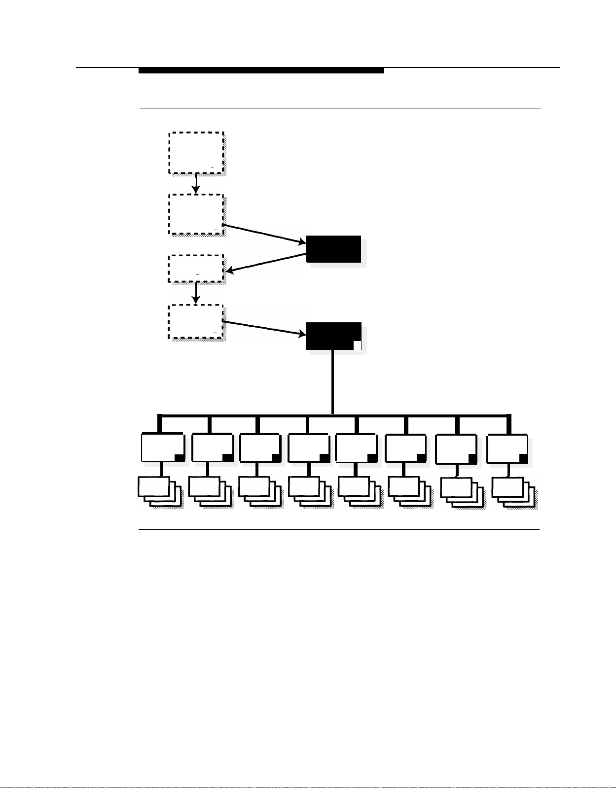
Figure 1-1 shows the main features associated with each service. A description
of the services and their associated features follows the illustration.
1-2
Overview of System Services and Features
Page 14

PARTNER MAIL Services
PARTNER MAIL System
Monolingual/Bilingual
Mode
Voice Mail Service
Allows subscribers to:
■
Send Messages
■
Listen to Messages
■
Reply to Messages
■
Forward Messages
■
Delete Messages
Record Personal Greeting
■
Administer a Personal
■
Operator
■
Change Password
■
Administer Outcalling
In bilingual mode, after logging
in, subscribers hear prompts in
the language administered for
their voice mailbox.
Immediate
Call Handling
The PARTNER MAIL
system answers
external calls. Callers
receive Automated
Attendant Service.
The receptionist
answers calls that
have overflowed from
the mail system.
Automated Attendant Service Call Answer Service
Allows callers to choose from
menu to:
Transfer to specific
■
extensions
■
Play pre-recorded
announcements
Can also:
■
Automatically route calls
■
Accept fax calls
■
Use programmed Business
Schedule
■
Provide customized afterhours service
In bilingual mode, callers can
choose to hear prompts in the
system’s primary or secondary
language.
Allows callers to leave a
message or transfer to another
extension when the called party
does not answer.
In bilingual mode, callers hear
the personal greeting in the
language administered for the
voice mailbox. Callers can
choose to hear prompts in the
alternate language.
Delayed
Call Handling
The receptionist
answers external
calls. Overflow calls
go to PARTNER
MAIL Automated
Attendant Service.
Figure 1-1. Overview of System Services and Features
Introduction
1-3
Page 15

PARTNER MAIL Services
Automated Attendant Service
Automated Attendant Service answers calls and plays a menu of options.
Callers can press buttons to select options, thereby determining how their calls
will be handled.
■
The Automated Attendant’s Main Menu can include options to:
Transfer the caller to an extension or mailbox that you specify.
—
Play a Submenu of additional options.
—
Play an Announcement containing frequently requested information
—
(such as directions to your office or your business hours).
Prompt the caller to dial a transfer destination. If callers are not
—
familiar with your extension numbers, you can create a Directory of
subscribers that they can use.
■
Callers using rotary phones or callers needing assistance are
automatically transferred based on the Dial 0/Timeout Action that you
specify. For example, callers can be transferred to a person of your
choice or to the Automated Attendant’s General Mailbox.
■
If many of your callers have rotary phones, you can turn on a
Touch-Tone Gate so those calls can be handled more quickly. In this
case, a Touch-Tone Gate Greeting plays before the Main Menu. In
bilingual mode this greeting enables callers to choose the language they
want to hear. For more information, see Greetings (System).
If the Touch-Tone Gate is off, the Main Menu is the first thing callers hear
when the Automated Attendant answers. If the mail system is in bilingual
mode, the Main Menu prompt enables callers to choose the language
they want to hear.
■
An Automated Attendant operates in day mode when the business is
open and in night mode when the business is closed. Each mode has its
own menu structure. The Schedule Controller determines whether the
Automated Attendant follows the communications system’s Night Service
setting or an independent schedule that you program.
■
You can choose to have one or up to three Automated Attendants. If you
have multiple Automated Attendants, each one has its own set of menus
and schedule. For more information, see Single/Multiple Automated
Attendant.
If you have multiple Automated Attendants, you must assign lines that are
designated for Automated Attendant Service using Group Call
Distribution (#206) Setting 1 to Automated Attendant 2 and Automated
Attendant 3. Any lines not assigned to Automated Attendant 2 or 3 are
answered by Automated Attendant 1. For more information, see Line
Assignments.
1-4
Overview of System Services and Features
Page 16

PARTNER MAIL Services
Interactions with the Communications System
Automated Attendant Service is used with the following communications system
features:
Group Call Distribution (#206) Setting 1 identifies the lines to be
■
answered by Automated Attendant Service.
VMS Hunt Schedule (#507) specifies when the communications system is
■
to route calls to Automated Attendant Service:
Always (factory setting).
—
Day Only (only when the communications system’s Night Service is
—
off).
Night Only (only when the communications system’s Night Service is
—
on).
VMS Hunt Delay (#506) specifies whether Automated Attendant Service
■
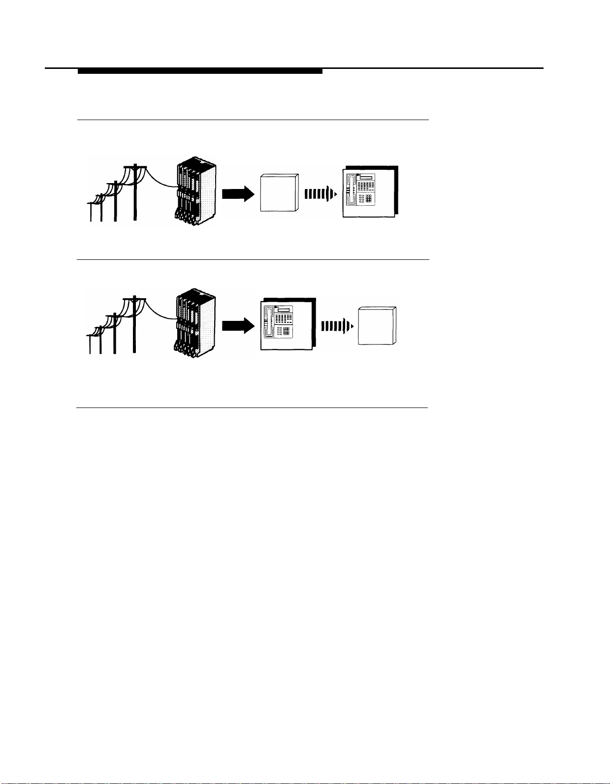
is to provide immediate or delayed call handling (see Figure 1-2):
Immediate (factory setting). Automated Attendant Service answers
—
calls on the second ring. The receptionist acts as backup. This allows
most calls to be routed to the correct destination without the
assistance of the receptionist.
Delayed. Automated Attendant Service answers calls after the fourth
—
ring. This delay gives the receptionist an opportunity to answer the
call if he or she is available.
Automated Attendant Service recognizes calls from fax machines that
produce industry-standard fax calling (CNG) tones. If VMS Hunt Delay is
set to Immediate, you can specify a fax extension or a fax Hunt Group to
which the Automated Attendant transfers fax calls. You also can specify
an extension to be notified when a fax arrives. For more information, see
Fax Extension and Fax Message Receiver.
For more information about these communications system features, see the
Programming and Use guide for your communications system.
Introduction
1-5
Page 17
PARTNER MAIL Services
Immediate Call Handling
Incoming Calls
Incoming Calls
Figure 1-2. Immediate and Delayed Call Handling
Here are a few simple ways to set up Automated Attendant Service:
Control Unit
PARTNER MAIL
answers on
the second ring
Receptionist
backs up
PARTNER MAIL
Delayed Call Handling
Control Unit answers incoming picks up unanswered
■ Case 1: The receptionist is the primary call handler. Automated
Attendant Service handles overflow.
Use Group Call Distribution (#206) Setting 1 to identify the lines to be
1.
answered by Automated Attendant Service.
Receptionist PARTNER MAIL
calls
calls after the fourth ring
2.
Set VMS Hunt Schedule (#507) to Always.
Set VMS Hunt Delay (#506) to Delayed.
3.
Case 2: Automated Attendant Service is the primary call handler.
■
Use Group Call Distribution (#206) Setting 1 to identify the lines to be
1.
answered by Automated Attendant Service.
Set VMS Hunt Schedule (#507) to Always.
2.
3.
Set VMS Hunt Delay (#506) to Immediate.
1-6
Overview of System Services and Features
Page 18

PARTNER MAIL Services
Case 3: The receptionist answers calls during the day; Automated
■
Attendant Service answers calls at night.
1.
Use Group Call Distribution (#206) Setting 1 to identify the lines to be
answered by Automated Attendant Service.
2.
Set VMS Hunt Schedule (#507) to Night Only.
3.
Set VMS Hunt Delay (#506) to Immediate.
Call Answer Service
Call Answer Service picks up unanswered calls and transfers them to predefine mailboxes. You must create a mailbox for each destination to which
callers can be transferred, with the following exceptions:
Fax Extensions should not have mailboxes.
—
The Call Answer Service Operator does not have to have a mailbox.
—
The Call Answer Service Operator is the extension to which you can
choose to transfer callers who need help.
There are four types of mailboxes that you can create.
■
A Call Answer Service mailbox provides message storage space. When
a caller reaches a Call Answer Service mailbox, the caller hears a
greeting. If the mail system is in bilingual mode and the subscriber
recorded a greeting in two languages, the caller can switch between the
two languages. The caller can record a message, review and edit it, and
transfer to another extension or an operator.
When a caller leaves a message, Call Answer Service turns On the
message light on the subscriber’s phone. If the subscriber’s mailbox has
Outcalling privileges and the subscriber has Outcalling turned On, Call
Answer Service calls the numbers specified by the subscriber. The
subscriber can remotely log in and retrieve the message.
■
A Bulletin Board Mailbox provides an information message up to four
minutes long. When a caller reaches a Bulletin Board mailbox, the caller
hears the message. The caller cannot leave a message, but can transfer
to another extension.
A Bulletin Board mailbox is particularly useful for information that
changes frequently. The information can be modified easily without
entering System Administration.
An Automated Attendant mailbox provides access to a pre-defined
■
Automated Attendant. A caller who reaches an Automated Attendant
mailbox hears whatever was recorded for that Automated Attendant. The
caller can make selections from the Automated Attendant’s menus.
Introduction
1-7
Page 19

PARTNER MAIL Services
A Transfer-Only mailbox allows transfer to an extension that does not
■
need message storage space, for example, the extension in a
conference room. When a caller reaches a Transfer-Only mailbox, the
caller hears a greeting. The caller cannot leave a message, but can
transfer to another extension.
You can create mailboxes of any type for Calling Groups and Hunt Groups.
When a caller reaches a Group Mailbox, the call is handled according to the
type of mailbox it is, as described above. If you create a Call Answer Service
mailbox for the group, you can assign a Group Mailbox owner. Then, when a
message is placed in the Group Mailbox, Call Answer Service turns On the
message light on the owner’s phone.
For more information about creating mailboxes, see Mailbox.
Interactions with the Communications System
Call Answer Service is used with the following communications system features:
■
Automatic VMS Cover (#310) is assigned to extensions for which
unanswered intercom and transferred calls are to be automatically routed
to Call Answer Service after a specified number of rings (3 rings for
Release 3.1 and earlier communications systems; 1 to 9 rings for later
communications systems).
■
VMS Cover can be programmed on a subscriber’s phone to turn VMS
Cover on and off. This button can be programmed regardless of the
Automatic VMS Cover setting for that extension. However, if Automatic
VMS Cover is Assigned and a VMS Cover button is programmed, the
subscriber must use the button to turn VMS Cover on.
■
Voice Mailbox Transfer can be programmed on a subscriber’s phone to
transfer callers directly to another subscriber’s mailbox without ringing
the other subscriber’s extension first. This feature is useful when one
subscriber is handling calls for another subscriber who is not at his or her
desk.
■
Group Call Distribution (#206) Setting 3 (VMS Line Cover) can be used to
identify lines on which calls go to a pre-defined mailbox after four rings. If
the mail system Line Ownership feature is used to assign an owner to a
line, calls go to the line owner’s mailbox. If Line Ownership is not used,
calls go to the General Mailbox for Automated Attendant 1.
■
Line Coverage (#208) can be used as an alternative to Group Call
Distribution Setting 3 to assign ownership for a line to an extension. Calls
on the owned line go to the line owner’s mailbox. This feature is available
only on communications system Release 4.0 and later.
1-8
Overview of System Services and Features
Page 20

PARTNER MAIL Services
Group Call Distribution (#206) Setting 3 and Line Coverage Extension
(#208) differ from each other in the following ways:
Distributio
*This setting applies to all extensions programmed for Voice Mail coverage.
For more information about these communications system features, see the
Programming and Use guide for your communications system.
Voice Mail Service
Voice Mail Service provides features that let subscribers manage their own
mailboxes. A subscriber with a Call Answer Service mailbox or a Transfer-Only
mailbox can:
■
Record a name and greetings that callers hear. Hearing the name and a
greeting in the subscriber’s voice reassures callers that they have
reached the correct destination.
Group Call
n
Setting 3
Line
Coverage
Extension
Calls normally Can send calls
go to
Mailboxes after mailboxes
4 rings
1-9 rings as Yes, using Do
specified by Not Disturb and
VMS Cover VMS Cover
Rings (#117)* button.
immediately to coverage on
No No
Can turn
and off
Yes, using
VMS Cover
button
The subscriber can record and store up to three greetings to cover
different situations. Then the subscriber can easily activate the
appropriate greeting without having to re-record it. If the system is in
bilingual mode, the subscriber can record up to three greetings in each
language. For more information, see Greetings (Personal).
■
Choose a password to keep messages in the mailbox confidential. The
subscriber should change the password regularly and keep it secure. For
more information, see Personal Mailbox Administration.
■
Choose the extension to receive the call if the caller presses [
0 ] before,
during, or after leaving a message. For more information, see Personal
Operator.
■
In bilingual mode, listen to Voice Mail prompts in the language
programmed for the mailbox. See Mailbox.
Introduction
1-9
Page 21

System Administrator’s Responsibilities
In addition, a subscriber with a Call Answer Service mailbox can:
■
Create and send messages. The subscriber can address a message to a
specific mailbox number, choose the mailbox from a list of subscribers,
or specify a pre-designated group of subscribers. For more information,
see Personal Mailbox Administration.
The System Administrator can send a message to all subscribers. For
more information, see Broadcast Messages.
■
Listen to messages from callers.
Reply to messages sent by subscribers with Call Answer Service
—
mailboxes.
Forward a received message to one or more subscribers with Call
—
Answer Service mailboxes, with additional comments if desired.
For more information, see Personal Mailbox Administration.
■
If the mailbox has Outcalling privileges, administer Outcalling from any
on-site or remote touch-tone phone:
Designate up to five phone numbers to be called when a message
—
arrives in the mailbox.
Specify the number of times the list of numbers is dialed.
—
Specify the times when Outcalling takes place.
—
—
Turn Outcalling On and Off.
System Administrator’s
Responsibilities
The mail system is set up to meet the needs of your business, based upon the
information that you provide prior to installation. As System Administrator, you
have two primary areas of responsibility after installation: system security and
routine maintenance.
System Security
Toll fraud is the unauthorized use of your telecommunications system by third
parties to make long-distance telephone calls. Under the law, you, the
customer, are responsible for paying for part or all of those unauthorized calls.
Thus the following information is of critical importance to you.
Criminals called hackers may attempt to gain unauthorized access to your
communications system and your mail system. Hackers often attempt to trick a
company’s employees into providing them with access to an outside line or an
outside operator.
1-10
Overview of System Services and Features
Page 22

System Administrator’s Responsibilities
Hackers may pose as telephone company employees or employees of AT&T,
Lucent Technologies, or your local authorized dealer. Hackers will go through a
company’s trash to find directories, dialing instructions, and other information
that will enable them to break into the system. The more knowledgeable they
appear to be about employee names, departments, telephone numbers, and
the internal procedures of your company, the more likely it is that they will be
able to trick an employee into helping them.
Hackers concentrate their activities in two areas related to the mail system:
■
They try to dial into a mailbox, then execute a transfer by dialing [ ★ ] [ T ].
Then they dial an access code, followed by a digit string to either direct
dial or access a network operator to complete the call.
■
They try to locate unused or unprotected mailboxes and use them as
drop-off points for their own messages.
Preventative Measures
The following measures should be taken on the communications system side to
limit the risk of unauthorized activity by hackers:
■
All lines should be removed from the Remote Maintenance Device using
Line Assignment (#301).
■
If Outcalling is not permitted, the extensions connected to the mail
system unit and the Remote Maintenance Device should be restricted to
Inside Only using Outgoing Call Restriction (#401). This denies access to
outside lines.
■
If Outcalling is permitted, Outgoing Call Restriction should be used with
Allowed and Disallowed Lists to meet the needs of the business while
maintaining the security of the system.
Security Alert:
Outcalling introduces the risk of toll fraud abuse. Outgoing Call
Restriction, Allowed Lists, and Disallowed Lists can reduce the risk.
Extensions connected to the mail system ports should be restricted
as much as the needs of the business allow.
For the extensions connected to port 1 on a two-port system, ports 1, 2,
and 3 on a four-port system, or ports 1 through 4 on a six-port system,
Outgoing Call Restriction should be set to Inside Only.
Introduction
1-11
Page 23

System Administrator’s Responsibilities
For the extensions connected to the Outcalling ports (port 2 on a two-port
system, port 4 on a four-port system or ports 5 and 6 on a six-port
system), Outgoing Call Restriction should be set to the most restrictive
value that the business allows; then Allowed and Disallowed Lists should
be assigned as needed. For example, if Outgoing Call Restriction is set
to Inside Only, an Allowed List containing all numbers to which Outcalls
are allowed must be created. This list must be assigned to the extensions
connected to port 2, port 4, or ports 5 and 6.
The following measures should be taken on the mail system side:
■
Create only mailboxes that are necessary and delete any unused
mailboxes.
■
Permit no Outcalling, or permit it only for those with a legitimate business
need.
■
Change the System Administrator’s Mailbox from the factory setting.
■
Set the System Administrator’s mailbox password to a hard-to-guess
value.
■
Set the System Administration Password to a hard-to-guess value.
■
Turn Off the Remote Maintenance Device when it is not in use.
Set the Minimum Password Length to 6 digits or more.
■
■
Set the Security Violation Notification action and number of
unsuccessful login attempts to the most restrictive values that the
business allows.
The following general precautions also should be taken:
■
Provide good physical security for the room containing your
telecommunications equipment and the room with administrative tools,
records, and System Administration information. These areas should be
locked when not attended.
■
Provide a secure trash disposal for all sensitive information, including
telephone directories, call accounting records, or anything that may
supply information about your communications system. This trash should
always be shredded.
1-12
Overview of System Services and Features
Page 24

System Administrator’s Responsibilities
Security Policy and User Education
As a safeguard against toll fraud, establish policies and educate all mail system
users:
■
All reports of trouble, requests to move extensions, or any other
administrative details associated with the communications system or the
mail system should be handled by one person (the System Administrator)
or within one department. Anyone claiming to be a telephone company
representative should be referred to this person or department.
■
If a caller claims to be an authorized telephone company representative,
verify his or her identity before permitting that person any access to the
system.
■
Establish well-controlled procedures for passwords.
Establish a specific date for changing passwords (for example, the
—
first of each month) and help users remember to do it.
Tell users what the Minimum Password Length is.
—
Tell users that passwords should not be recycled. They should be
—
hard to guess and should not contain:
■
All the same numbers (for example, 666666).
■
Sequential characters (for example, 123456).
■
Personal information that can be associated with them (such as
their name, birthdate, telephone number, or social security
number).
Discourage the practice of writing down passwords, If a password
—
needs to be written down, keep it in a secure place and never discard
it while it is still active.
Tell users never to program passwords onto Auto Dial buttons.
—
Display phones reveal the programmed numbers and internal abusers
can use the Auto Dial buttons to originate unauthorized calls.
■
Educate employees that hackers may try to trick them into providing
them with dial tone or dialing a number for them.
■
Ask users to tell you if any of the following suspicious activity occurs:
Inability to log into Voice Mail.
—
Lost mail messages, mailbox lockout, or altered greetings.
—
Inability to get an outside line.
—
Series of calls where there is silence on the other end or the caller
—
hangs up.
Sudden increase in wrong numbers.
—
—
Caller complaints that your lines are busy
Introduction
1-13
Page 25

System Administrator’s Responsibilities
Callers claiming to be the “phone” company. Ask for a callback
—
number.
Callers trying to obtain sensitive information or asking for assistance in
—
placing outside or long-distance calls. Ask for a callback number.
Increases in internal requests for assistance in making outside calls
—
(particularly international calls or requests for dial tone).
■
Make users with Outcalling privileges aware of the potential risks and
their responsibilities.
■
Never distribute the office telephone directory to anyone outside the
company.
■
Collect old office telephone directories and shred them.
■
Never discuss your telephone system’s numbering plan with anyone
outside the company.
■
Never accept collect telephone calls from unknown callers.
■
Any time a call appears to be suspicious, call the National Service
Assistance Center at 1 800 628-2888.
■
You should also take advantage of AT&T monitoring services and
devices, such as the NetPROTECT
CAS with HackerTracker®, and CAT Terminal with Watchdog. Call
1 800 638-7233 to get more information about these products and
services.
SM
family of fraud-detection devices,
Routine Maintenance
The following list is intended to give you an idea of the types of tasks involved in
routine maintenance:
■
Assigning a Call Answer Service Operator, General Mailbox Owners, Fax
Message Receivers, and Group Mailbox Owners. Be sure that people
designated to serve in these roles are aware of what is expected of them.
Refer them to the User’s Guide for a description of their responsibilities.
■
Maintaining mailboxes. Tasks typically involve adding and deleting
mailboxes to accommodate personnel changes, and initializing mailbox
passwords if subscribers forget them.
■
Maintaining Group Lists to facilitate sending messages to groups of
subscribers. Be sure to keep subscribers informed about the lists.
■
Resetting System Time, for example, if you are in an area that observes
daylight saving time.
■
Maintaining the Business Schedule to accommodate holidays, temporary
closings or openings, and changes to your company’s hours of
operation.
1-14
Overview of System Services and Features
Page 26

System Administrator’s Responsibilities
■
Changing greetings, menus, and announcements to accommodate
changes in personnel, your company’s operations and/or services.
For programming instructions, see the appropriate feature in Chapter 5. Be sure
to update the planning forms so that they accurately reflect the programming
for your mail system. You can make a copy of the mail system Planning Forms
in Appendix A.
Helpful Programming Hints
After you become familiar with the mail system, the following hints and shortcuts
can save you time:
■
You can program the mail system from any touch-tone telephone.
■
When logging in from your own extension, simply press [
prompted to enter your extension and [
# ]. You do not have to enter your
# ] when you are
extension number.
■
You never need to wait for a greeting or prompt to finish playing before
you press a button.
■
Press [ ★ ] [ 7 ] at any time during programming to return to the System
Administration Menu.
■
Press [ ★ ] [ # ] to return to the previous menu.
■
Press [ ★ ] [ 4 ] to repeat the current menu or prompt.
■
Press [ ★ ] [ ★ ] [ 9 ] to exit the mail system, or hang up.
■
Use the handset, not the speakerphone, for recording.
■
If you use the speakerphone when programming, turn off the
microphone.
Introduction
1-15
Page 27

Installation
Contents
2
Introduction
Preparing for Installation
Mail System Hardware
■
■ Communications System Hardware
■
Mail System Site Requirements
Installing the Mail System
Mounting the System Unit
■
■
Connecting to the Communications System
■
Connecting to the Remote Maintenance Device
2-1
2-1
2-2
2-2
2-3
2-5
2-5
2-7
2-9
Installation
2-i
Page 28

The exclamation point in an equilateral triangle is intended to alert the user to the
presence of important operating and maintenance (servicing) instructions in the
literature accompanying the product.
IMPORTANT SAFETY INSTRUCTIONS
When installing telephone equipment, always follow basic safety precautions to reduce
the risk of fire, electrical shock, and injury to persons, including:
■
Read and understand all instructions. (Pay particular attention to
Communications System Hardware on page 2-2 and Mail System Site
Requirements on page 2-3.)
■
Follow all warnings and instructions marked on or packed with the product.
■
Never install this unit or telephone wiring for it during a lightning storm.
■
Never install a telephone jack in a wet location unless the jack is specifically
designed for wet locations.
■
Never touch uninsulated telephone wires or terminals unless the telephone
wiring has been disconnected at the network interface.
■
Use caution when installing or modifying telephone lines.
Use only PARTNER modules in the PARTNER communications system control
■
unit.
Use only recommended/approved PARTNER communications system
■
accessories.
■
Do not install this product near water, for example, in a wet basement location.
■
Do not overload wall outlets, as this can result in the risk of fire or electrical
shock.
■
The mail system is equipped with a three-wire grounding-type plug with a third
(grounding) pin. This plug will fit only into a grounding-type power outlet. This is
a safety feature. If you are unable to insert the plug into the outlet, contact an
electrician to replace the obsolete outlet. Do not defeat the safety purpose of the
grounding plug.
■
Do not attach the power supply cord to building surfaces. Do not allow anything
to rest on the power cord. Do not locate this product where the cord will be
abused by persons walking on it.
■
Vents on the sides of the cabinet are provided for ventilation. To protect this
equipment from overheating, do not block these openings.
■
Never push objects of any kind into this product through vent openings in the
unit, as they may touch dangerous voltage points or may short out parts, which
could result in a risk of fire or electrical shock. Never spill liquid of any kind on
this product.
If there is not sufficient room on the existing wood mounting surface, either
■
secure a new surface (a piece of plywood) or use wall studs to install the mail
system unit. This ensures permanent mounting and prevents wall damage.
Unplug the product from the wall outlet before cleaning. Dust with a soft cloth.
■
Do not use cleaners or aerosol cleaners.
Do not operate the system if chemical gas leakage is suspected in the area. Use
■
telephones located in some other safe area to report the trouble.
2-ii
WARNING:
DO NOT open the mail system unit. There are no user-serviceable parts inside the
unit Only an authorized technician should open the unit for required maintenance
or upgrading purposes.
SAVE THESE INSTRUCTIONS
Installation
Page 29
Installation
Introduction
2
This chapter explains how to install the mail system hardware. It is intended for
qualified installers only.
WARNING:
Installation should be performed only by a qualified installer.
Preparing for Installation
Read this entire chapter before you begin the installation. Verify that you have
all the required components, and that your installation site meets the
requirements specified in this chapter.
You should have a copy of communications system Planning Form B1 that
shows extension assignments for the mail system hardware.
NOTE:
Outside of the United States, some telephone networks provide a tone
similar to the U.S. busy tone to signal that the far-end caller has hung-up.
If the mail system needs to respond to this signal, DIP switches need to
be reset on the voice processing cards before the system unit is
installed. See Chapter 7, “Upgrading the System.”
Installation
2-1
Page 30

Preparing for Installation
Mail System Hardware
The mail system includes the following hardware components:
■
Mail system cabinet
■
Wall mount and cable manager bracket
7-foot (2.13m) modular D4BU telephone cords (two-pair, standard phone
■
connection)— 2 for a two-port system, 4 for a four-port system, or 6 for a
six-port system.
■
Power cord—6-foot (1.83m), 3-prong, male/female ends
■
Modem cable
■
Four No. 8 3/4-inch pan-head sheet metal screws for mounting the
system unit on plywood.
NOTE:
The cabinet and bracket together are referred to as the system
unit.
NOTE:
If you are mounting the system unit on a surface other than
plywood, you will need 4 No. 8 screws of the appropriate type for
the wall and the weight of the system unit. For example, if
mounting to wall studs through drywall, use No. 8 1-3/4-inch (or
longer) pan-head sheet metal screws.
■
Remote Maintenance Device and one modular telephone cord (shipped
in a separate box).
Communications System Hardware
The following communications system equipment is required to install the mail
system:
■
PARTNER II Release 3 or later or PARTNER Plus Release 3.1 or later
processor module
■
206 modules, Release 2 or later
NOTE:
You can connect up to five voice mail ports on a 206 module.
The top, or first, port on a 206 module is the power-failure port and
should NOT be used to connect either a voice mail port or the
Remote Maintenance Device.
2-2
Installation
Page 31

Preparing for Installation
■
A sufficient number of touch-tone receivers on the communications
system modules. Each 206 and 200 module has one touch-tone receiver;
each 400 module has two.
Touch-tone receivers are shared by the mail system and the communications
system. The mail system uses one each time it transfers a call, turns a phone’s
message light On or Off, or Outcalls. The communications system uses one
each time a standard device dials a call (intercom or outside).
The total number of touch-tone receivers required is dependent on the amount
and type of traffic that the communications system and the mail system handle.
In addition to the touch-tone receivers needed to support all of the standard
devices in the communications system, one touch-tone receiver generally is
needed for every two mail system ports. A very heavily used system may
require more touch-tone receivers.
Mail System Site Requirements
Table 2-1. Mail System Requirements
Condition
Relative Humidity
Temperature Range
Air Quality
Environment
Dimensions
Voltage
Weight
FCC Number
Ringer Equivalence Number (REN)
TDD Compatibility
Maximum Number of Ports
The system unit should be wall-mounted adjacent to the communications
system control unit on the same wood mounting surface, if possible.
Requirement
8-85%
Recommended: 60°F–80°F (16°C–27°C)
Maximum: 40°F–104°F (4°C–40°C)
Dust-free area (preferably in an office
environment)
No exposure to any liquids (avoid areas
near drinking fountains, coffee makers,
and so on)
Adequate clearance around vents to
allow for air flow
Cabinet: 12” high x 14.5” wide x 5-5/8”
deep
Bracket: 10-7/8” high x 17-1/4” wide
115 or 230 VAC
~26 lb.
EAG USA-21253-VM-E
0.7B
None
6
Installation
2-3
Page 32

Preparing for Installation
WARNING:
If there is not sufficient room on the existing wood mounting surface,
either secure a new surface (a piece of plywood) or use wall studs to
install the system unit. This ensures permanent mounting and will prevent
wall damage.
The system unit should be connected to the same electrical branch circuit as
the communications system control unit. If the communications system’s control
unit is connected to an uninterruptible power supply (UPS) or surge protector, it
is recommended that the mail system unit be connected to the same UPS or
surge protector.
2-4
Installation
Page 33
Installing the Mail System
Installing the Mail System
Installation involves the following activities:
■
Mounting the system unit.
■
Connecting the system unit to the communications system.
■
Connecting the Remote Maintenance Device to the system unit.
NOTE:
The illustrations show a six-port system; if you are installing a two-port or
four-port system, it will look slightly different.
Mounting the System Unit
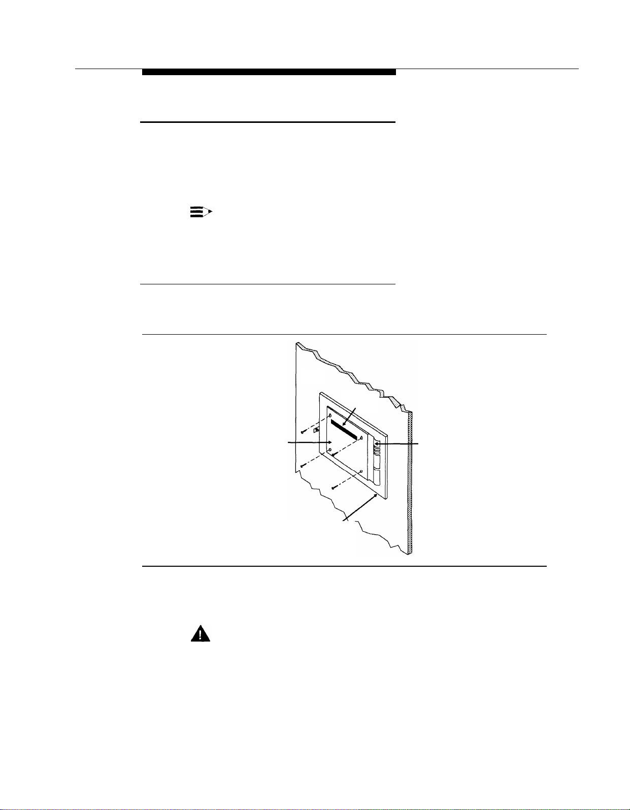
Position the bracket against the wall so that the hanger slot is located near
1.
the top, as shown in Figure 2-1.
Bracket
Wood Mounting
Figure 2-1. Mounting the Bracket
2.
Using the bracket as a template, mark the four points on the wall where the
screws will be inserted.
WARNING:
Be sure the bracket will be screwed into wall studs or a piece of plywood
to ensure permanent mounting and to prevent wall damage.
Wall
Hanger
Slot
Cable Manager
Surface
Installation
2-5
Page 34

Installing the Mail System
3.4.Screw the bracket securely to the wall, using the screws provided or their
equivalents. For mounting to wall studs through drywall, use four No. 8 1-3/4inch (or longer) pan-head sheet metal screws.
Position the cabinet securely on the bracket, placing the cabinet’s bracket
lip into the hanger slot on the bracket, as shown in Figure 2-2.
Right
Side
Panel
Bracket
Lip Captive
Retaining
Screw
Figure 2-2. Mounting the Cabinet
Tighten the captive retaining screw on the cabinet’s left side panel to secure
5.
the cabinet to the bracket.
2-6
Installation
Page 35

Installing the Mail System
Connecting to the Communications System
Route the telephone cords through the slots on the bracket and connect
1.
them to the appropriate ports on the system unit as shown in Figure 2-3.
Figure 2-3. Connecting Cords to the System Unit
Connect the other end of the cords to extension jacks on 206 module(s) in
2.
the communications system control unit. Refer to the PARTNER MAIL
column on communications system Planning Form B1 for extension
assignments.
3. Set the voltage selector switch to the appropriate voltage, 115V or 230V.
Bracket
Lip
Captive
Retaining
Screw
Mounting
Hole
Power
Supply
Vents
(Do not block)
Voltage
Selector
Figure 2-4. System Unit (Back and Left Side View)
Installation
2-7
Page 36

Installing the Mail System
Plug the power cord into the system unit’s AC power socket (see
4.
Figure 2-5).
Ports 1 & 2
Ports 3 & 4
Ports 5 & 6
Status
Indicator
Lights
COM 1 Port
(Remote Maintenance
Device Connector)
COM 2 Port
(Not Used)
Power
Switch
AC
Power
Vents
(Do Not Block)
Right Side
Panel
Serial Comcode
Number Label
Label
Figure 2-5. System Unit (Front and Right Side View)
5. Plug the system unit into a grounded AC electrical source, preferably on the
same branch circuit as the communications system.
6.
Turn on the power switch.
2-8
Installation
Page 37

Installing the Mail System
Connecting to the Remote Maintenance Device
(Front View)
REMOTE MAINTENANCE DEVICE Mk III
(Back View)
DC On/Off RS–232–C Telephone
Power In
Switch
Port Line Port
Figure 2-6. Remote Maintenance Device
1.
Use the modem cable provided to connect the RS-232-C port on the Remote
Maintenance Device (see Figure 2-6) to the COM1 port on the system unit
(see Figure 2-5).
2.
Use a modular telephone cord to connect the Telephone Line Port on the
Remote Maintenance Device (see Figure 2-6) to an extension jack on the
206 module. Refer to Communications System Planning Form B1 for the
correct extension number.
Attach one end of the power cord to the DC Power In jack on the Remote
3.
Maintenance Device (see Figure 2-6) and plug the other end into a
grounded AC electrical source.
Turn on the on/off switch (see Figure 2-6). Verify that the AA, TR, and MR
4.
LEDs on the front of the Remote Maintenance Device are lit.
Turn off the Remote Maintenance Device.
5.
Write the 206 module extension jack number on a label and affix the label to
6.
the Remote Maintenance Device. Keep the extension jack number handy.
You may need it if the mail system needs servicing.
Security Alert:
Keep the Remote Maintenance Device turned off unless your mail system
needs servicing and service personnel need remote access to your
system.
Installation
2-9
Page 38

Mail System Initial
Programming
Contents
3
Introduction
Before You Begin
Completing Planning Forms
■
Preparing the Communications System
■
Hunt Group Extensions
Line Access Mode
Transfer Return Extension
Outgoing Call Restriction
Line Assignment for the Remote Maintenance Device
Automatic Extension Privacy for the Remote Maintenance
Device
Logging In to System Administration
Programming the Mail System
Accessing the System Administration Menu
■
Initial Programming Quick Reference
■
Programming System Parameters
■
System Language
Maximum Digit Length
Single or Multiple Automated Attendant
Automated Attendant Line Assignments
Programming Mailboxes
■
Considerations for Creating Mailboxes
Creating Mailboxes
Assigning a Group Mailbox Owner
Specifying Fax Extensions and System Mailboxes
■
Fax Extension and Fax Message Receiver
Call Answer Service Operator
3-1
3-1
3-1
3-2
3-2
3-3
3-3
3-4
3-4
3-5
3-5
3-8
3-8
3-9
3-11
3-12
3-12
3-12
3-13
3-14
3-15
3-15
3-16
3-17
3-17
3-18
Mail System Initial Programming
3-i
Page 39

Contents
General Mailbox Owner
System Administrator’s Mailbox
■ Programming the Schedule
System Date and Time
Schedule Controller
Business Schedule
Setting the Touch-Tone Gate
■
Recording System Greetings
■
Recording Touch-Tone Gate Greetings
Recording a Voice Mail Greeting
Programming the Automated Attendant Menus
■
Recording Announcements
Creating Submenus
Programming Day and Night Menus
Creating Group Lists
■
Assigning Line Ownership
■
Setting System Security Options
■
Minimum Password Length
Security Violation Notification
After Initial Programming
Assigning the System Administrator’s Mailbox Password
■
■ Assigning a System Administration Password
3-18
3-18
3-19
3-20
3-20
3-21
3-22
3-23
3-24
3-25
3-26
3-26
3-27
3-28
3-30
3-31
3-32
3-33
3-33
3-34
3-34
3-34
3-ii
Mail System Initial Programming
Page 40

Mail System Initial Programming
Introduction
This chapter provides programming procedures for the installer of the mail
system. These procedures are required for correct operation of the system.
Since certain features (for example, language selection) must be programmed
before other features (such as voice mailbox assignments), perform the
procedures in the order in which they are presented in this chapter.
3
Before You Begin
Before you begin to program the mail system, you must have completed
planning forms and you must prepare the communications system.
Comlpeting Planning Forms
To perform the procedures in this chapter, you need the following forms:
■ Communications System Planning Forms B1 and B2
■
Mail System Planning Forms A through N
For information about filling out the planning forms, see Appendix A, “Mail
System Planning” and Appendix B, “Communications System Planning.”
Mail System Initial Programming
3-1
Page 41

Before You Begin
Preparing the Communications System
You must program a few communications system features before you program
the mail system. The following instructions assume that you are familiar with
communications system programming. If you are not, refer to the Programming
and Use guide for the communications system.
For these procedures, you need communications system Planning Forms B1
and B2 to identify the extension numbers associated with the mail system unit
and the Remote Maintenance Device.
Hunt Group Extensions
Use this procedure to assign the extensions associated with the mail system
unit to Hunt Group 7, the VMS Hunt Group.
At extension 10 or 11, press [
1.
Press [ # ] [ 5 ] [ 0 ] [ 5 ].
2.
At the Group:
3.
At the Extension: prompt, enter the first PARTNER MAIL extension
4.
prompt, press [
Feature
] [ 0 ] [ 0 ] [
7 ].
System Program
] [
System Program
number specified on communications system Planning Form B1.
NOTE:
The first extension jack on 206 modules should not be used as a
PARTNER MAIL extension. These jacks should be reserved for use
during a power failure.
5.
6.
Press [
Press [
Next Data
Next Item
] until the display reads
] or [
Prev Item
] until the next PARTNER MAIL extension number
1 Assigned.
displays.
Press [
7.
If additional PARTNER MAIL extensions are specified on Form B1, repeat
8.
Next Data
] until the display reads
1 Assigned.
Steps 6 and 7 for each one.
If this is a PARTNER II system in Hybrid mode, continue with “Line Access
9.
Mode” on page 3-3. Otherwise, go to “Transfer Return Extension” on
page 3-3.
].
3-2
Mail System Initial Programming
Page 42

Before You Begin
Line Access Mode
NOTE:
This procedure applies only to PARTNER II systems in Hybrid mode.
If communications system Planning Form B2 indicates that the extensions
associated with the mail system unit and the extension where the Remote
Maintenance Device is installed are Pooled extensions, use the following
procedure to change them to Key extensions:
Press [ # ] [ 3 ] [ 1 ] [ 3 ].
1.
At the
2.
number specified on communications system Planning Form B1.
Extension:
prompt, enter the first PARTNER MAIL extension
3.
4.
Press [
Press [
Next Data
Next Item
displays.
Press [
5.
Repeat Steps 4 and 5 for each PARTNER MAIL extension and for the
6.
Next Data
extension where the Remote Maintenance Device (VMS-RMD) is installed.
Continue with “Transfer Return Extension.”
7.
Transfer Return Extension
For extensions associated with the mail system unit, use the following
procedure. If the mail system transfers a call to an extension that has no Voice
Mail coverage, or if Voice Mail coverage is Off, and that extension does not
answer, the communications system transfers the call to the Transfer Return
Extension.
For extensions that do not have Voice Mail coverage, this procedure ensures
that unanswered calls transferred by the mail system return to the designated
extension, where they ring until answered.
1.
Press [ # ] 3 ] [ 0 ] [ 6 ].
At the Extension:
2.
specified on communications system Planning Form B1.
] until the display reads
] or [
Prev Item
] until the next PARTNER MAIL extension number
] until the display reads
prompt, enter the first PARTNER MAIL extension
2 Key.
2 Key.
At the Data:
3.
prompt, enter the Transfer Return Ext. No. specified on Form
B1, typically extension 10.
4.
Press [
Next Item
] or [
Prev Item
] until the next PARTNER MAIL extension number,
specified on communications system Planning Form B1, displays.
At the Data:
5.
prompt, enter the Transfer Return Ext. No.
Mail System Initial Programming
3-3
Page 43

Before You Begin
6.
If additional PARTNER MAIL extensions are specified on Form B1, repeat
Steps 4 and 5 for each one.
7.
Repeat Steps 4 and 5 for each extension that does not have Voice Mail
coverage.
8.
Continue with “Outgoing Call Restriction.”
Outgoing Call Restriction
Use this procedure to restrict all extensions associated with the mail system unit
and the Remote Maintenance Device from making outside calls.
Security Alert:
This procedure must be followed to limit the possibility of toll fraud abuse.
1.
Press [ # ] [ 4 ] [ 0 ] [ 1 ].
At the Extension:
2.
Maintenance Device (VMS-RMD) is installed as specified on
communications system Planning Form B1.
3.
4.
Press [
Press [
Next Data
Next Item
] until the display reads
] or [
specified on Form B1 is displayed.
Press [
5.
Repeat Steps 4 and 5 for each PARTNER MAIL extension.
6.
7.
Continue with “Line Assignment.”
Next Data
] until the appropriate value displays.
NOTE:
If Outcalling is permitted, be sure to create Allowed and Disallowed
Phone Lists as needed for Outcalling numbers. Instructions are
provided in Chapter 4.
Line Assignment for the
Remote Maintenance Device
Use this procedure to remove all lines from the extension to which the Remote
Maintenance Device is connected.
prompt, enter the extension number where the Remote
2 Inside Only.
Prev Item
] until the first PARTNER MAIL extension number
Security Alert:
This procedure must be followed to limit the possibility of toll fraud abuse.
1.
Press [ # ] [ 3 ] [ 0 ] [ 1 ].
3-4
Mail System Initial Programming
Page 44

Logging In to System Administration
At the
2.
Extension:
Maintenance Device (VMS-RMD) is installed as specified on
communications system Planning Form B1.
prompt, enter the extension number where the Remote
Press [
3.
4.
Continue with “Automatic Extension Privacy.”
Remove
] to remove all existing line assignments.
Automatic Extension Privacy for the Remote Maintenance Device
Use this procedure to assign Automatic Extension Privacy to the extension to
which the Remove Maintenance Device is connected so that users cannot
interrupt transmission.
Press [ # ] [ 3 ] [ 0 ] [ 4 ].
1.
At the Extension:
2.
prompt, enter the extension number where the Remote
Maintenance Device (VMS-RMD) is installed as specified on
communications system Planning Form B1.
3.
4.
Press [
Press [
Next Data
Feature
] until the display reads
] [ 0 ] [ 0 ] to exit programming.
1 Assigned.
Logging In to System Administration
To program the mail system, you will log in to the System Administrator’s
mailbox and access the System Administration Menu.
For initial programming, you will use the factory setting for the System
Administrator’s mailbox. The System Administrator’s mailbox password and the
Administration password are not factory-set, so you will be prompted to set
them. Be sure the System Administrator knows the passwords that you choose,
because the System Administrator will need them in the future to log in.
Security Alert:
It is strongly recommended that the System Administrator change the
System Administrator’s mailbox password and the System Administration
Password after initial programming is complete. Instructions are provided
at the end of this chapter.
Press [
Intercom
1.
] [ 7 ] [ 7 ] [ 7 ].
The Voice Mail Greeting plays, followed by the extension prompt.
Mail System Initial Programming
3-5
Page 45

Logging In to System Administration
Enter the System Administrator’s mailbox number + [
2.
NOTE:
Until you change it, the System Administrator’s mailbox is 9997.
The password prompt plays.
Press [ # ].
3.
NOTE:
Until you create it, the System Administrator’s mailbox password is
not set. After you press #, you are prompted to change the
password. Follow the prompts to enter a password. This password
must be used in the future to log in to the System Administrator’s
mailbox.
The Voice Mail Activity Menu plays.
Press [ 9 ] for System Administration.
4.
NOTE:
This option is not spoken in the Voice Mail Activity Menu. The option
is deliberately hidden to minimize the system’s vulnerability to
abuse.
The password prompt plays.
# ].
5.
Press [ # ].
NOTE:
Until you create it, the Administration password is not set. After you
press [
# ], you are prompted to change the password. Follow the
prompts to enter a password; it must be different from the System
Administrator’s mailbox password. The System Administration
password must be used in the future to access System
Administration.
The System Administration Menu plays.
Figure 3-1 illustrates the login procedure and shows the options available from
the System Administration Menu.
3-6
Mail System Initial Programming
Page 46
Logging In to System Administration
Enter System
Administrator’s
Mailbox
Number + [ # ]
Enter System
Administrator’s
Mailbox
#
Press
[ # ]
]
#
]
Password + [
Enter System
Administration
Password + [
Voice Mail
Activity
Menu
System
Administration
Menu
9
System
Paramters
Schedule
1 2 3 4 5
Automated
Attendant
Figure 3-1. Mail System Login
Mailboxes
Group
Lists
Line
Ownership
System
Greetings
6
7
Mail System Initial Programming
System
Security
8
3-7
Page 47

Programming the Mail System
Programming the Mail System
All of the procedures in this chapter are shown in short form. For more detailed
instructions, see the appropriate section in Chapter 5, “Features.”
Accessing the System Administration Menu
All procedures in this chapter start from the System Administration Menu. This is
the menu that you access when you log in to the System Administrator’s
Mailbox, as described in the previous section, “Logging In to System
Administration” on page 3-5.
If you are already logged in, you can return to the System Administration Menu
by doing one of the following:
■
Pressing [ ★ ] [ 7 ] to return directly to the System Administration Menu.
■
Pressing [
the “For System Parameters, press [ 1 ]” prompt.
For an overview of the procedural flow described in this chapter, and
information about the relationship between the procedures and the mail system
planning forms, refer to “Initial Programming Quick Reference,” which follows.
★
] [ # ] repeatedly to back up, one level at a time, until you hear
3-8
Mail System Initial Programming
Page 48

Programming the Mail System
Initial Programming Quick Reference
From the System
Administration Menu, Select...
1 System Parmeters
[ 9 ] System Language
Primary
Secondary
8
] Maximum Digit Length
[
1
] Single or Multiple Automated Attendant
[
3 Automated Attendant
[ 6 ] Line Assignments
[ 2 ] Add a Line
4 Mailboxes
[ 4 ] Create a Mailbox
7
] Assign a Group Mailbox Owner
[
1 System Parameters
[ 4 ] Fax Extension and Fax Message Receiver
[ 1 ] Fax Extension
[ 2 ] Fax Message Receiver
[ 5 ] Call Answer Service Operator
[ 6 ] General Mailbox Owner
[ 7 ] System Administrator's Mailbox
Go to Mail
System Planning...
Form A
Form A
Form A
Form A
Form A
Form A
Form B
Form B
Form C
Form C
Form C
Form C
Form C
2 Schedule
[ 1 ] System Time and Date
2
] Automated Attendant Schedule
[
1
] Schedule Controller
[
2
] Weekly Business Schedule
[
3 Automated Attendant
[ 5 ] Touch-Tone Gate
No Form
Form D
Form D
Form E
Mail System Initial Programming 3-9
Page 49

Programming the Mail System
From the System
Administration Menu, Select...
7 System Greetings
[ 3 ] Touch-Tone Gate Greeting
[ 1 ] Day
[ 1 ] Record Greeting
[ 2 ] Night
[ 1 ] Record Greeting
[ 1 ] Voice Mail Greeting
1
] Record Greeting
[
3 Automated Attendant
[ 4 ] Announcements
7
] Record Announcement
[
[ 3 ] Submenus
[ 4 ] Create Submenu
[ 1 ] Day Menu
6
] Modify Menu
[
2
] Night Menu
[
6
] Modify Menu
[
5 Group Lists
[ 4 ] Create a Group List
Go to Mail
System Planning...
Form E
Form E
Form F
Form K
Form J and I
Forms H and G
Forms H and G
Form L
6 Line Ownership
[ 4 ] Assign Line Ownership
8 System Security
[ 2 ] Minimum Password Length
3
] Security Violation Notification
[
4
] System Administration Password
[
Form M
Form N
Form N
3-10
Mail System Initial Programming
Page 50

Programming the Mail System
Programming System Parameters
Following is a list of the factory settings for the system parameters covered in
this section:
Parameter
System Language
Maximum Digit Length
Single or Multiple Automated
Factory Setting
Monolingual, English
2
Single
Attendant
Check mail system Planning Form A to see if you need to change any of these
factory settings.
■
If you do NOT, skip to “Programming Mailboxes” on page 3-14.
■
If you do, continue with the procedures in this section. For these
procedures, you select the System Parameters option from the System
Administration Menu. The System Parameters Menu plays. Figure 3-2
shows the options available from the System Parameters Menu.
System
Administration
Menu
System
Parameters
9
1
Single or
Multiple
Automated
Attendant
Fax Extention
and
Fax Message
Receiver
1 4 5 6 7
Call Answer
Service
Operator
General
Mailbox
Owner
Figure 3-2. System Parameters Administration
System
Administrator
Mailbox
Maximum
Digit
Length
Language
8
Mail System Initial Programming
System
9
3-11
Page 51

Programming the Mail System
System Language
Use this procedure to specify whether the mail system operates in monolingual
or bilingual mode, and to identify the system languages specified on mail
system Planning Form A. For more information, see Language in Chapter 5.
From the System Administration Menu, press [
1.
Press [ 9 ] for System Language.
2.
1
Press [
3.
Press [
4.
Bilingual only: Repeat Step 4 for the secondary language.
5.
Press [ ★ ] [ # ] to approve or [ 1 ] to re-enter the language.
6.
] for monolingual or [ 2 ] for bilingual.
1
] for English, or [ 2 ] for French, or [ 3 ] for Spanish.
Maximum Digit Length
Use this procedure to specify the maximum number of digits that a caller or
subscriber can dial to transfer to an extension or mailbox. This parameter is
specified on mail system Planning Form A. For more information, see Maximum
Digit Length in Chapter 5.
From the System Administration Menu, press [
1.
2.
3.
Press [
Press [
8 ] for Maximum Digit Length.
2 ], [ 3 ],or [ 4 ] to indicate the maximum number of digits.
Single or Multiple Automated Attendant
Use this procedure to specify whether the mail system uses one or up to three
Automated Attendants as specified on mail system Planning Form A. For more
information, see Single/Multiple Automated Attendants in Chapter 5.
1 ] for System Parameters.
1 ] for System Parameters.
3-12
1.2.From the System Administration Menu, press [
Press [
3.
Press [ 1 ] for Single or [ 2 ] for Multiple.
1 ] for Single or Multiple Automated Attendant Operation.
1 ] for System Parameters.
If you selected Multiple in Step 3, you must also program Automated Attendant
Line Assignments, as described in the next procedure. If you selected Single in
Step 3, skip to “Programming Mailboxes” on page 3-14.
Mail System Initial Programming
Page 52

Programming the Mail System
Automated Attendant Line Assignments
Figure 3-3 shows the options available from the Automated Attendant Menu.
System
Administration
Menu
Automated
Attendant
Automated
Attendant
Number
Assignments
9
3
Line
6
Review
Assigned
Lines
1
Add
Line
2
Figure 3-3. Automated Attendant Line Assignments
This procedure applies only to a Multiple Automated Attendant system. Use it to
assign the lines that should be answered by Automated Attendant 2 and 3 as
specified on mail system Planning Form A. Lines to be answered by Automated
Attendant 1 do not need to be assigned. (All lines identified on communications
system Planning Form A in the VMS-AA column and not assigned to Automated
Attendant 2 or 3 are assigned automatically to Automated Attendant 1.) For
more information, see Line Assignments in Chapter 5.
1.
From the System Administration Menu, press [
Press Automated Attendant Number [ 2 ] or [ 3 ].
2.
6
Press [
3.
Press [
4.
Enter the line number + [
5.
] for Line Assignments.
2
] to add a line.
#
].
Delete
Line
✳ D
3 ] for Automated Attendant.
Mail System Initial Programming
3-13
Page 53

Programming the Mail System
Repeat Step 5 until finished.
6.
7..
Press [ ★ ] [ # ] to quit.
8.
If you need to assign lines for another Automated Attendant, press [ ★ ] [ 7 ].
Then repeat from Step 2.
Programming Mailboxes
Programming mailboxes includes creating mailboxes and assigning Group
Mailbox Owners. You must create the mailboxes before you can perform the
remaining mail system procedures.
■
Mailboxes for extensions 10 through 57, Calling Groups 71 through 74,
and Hunt Groups 771 through 776 are not factory-set; you must create
the mailboxes that are needed as specified on mail system Planning
Form B.
■
Group Mailbox Owners are not factory-set.
To perform these procedures, you select the Mailboxes option from the System
Administration Menu. The Mailboxes Menu plays. Figure 3-4 shows the options
available from the Mailboxes Menu.
Play a
Mailbox
Configuration
2
Create a
Mailbox
Figure 3-4. Mailbox Administration
System
Administration
Menu
Mailboxes
Modify a
Mailbox
4
9
4
Delete a
Mailbox
6
✳ D 7
Assign a Group
Mailbox Owner
3-14
Mail System Initial Programming
Page 54

Programming the Mail System
Considerations for Creating Mailboxes
Remember the following as you create mailboxes:
■
You can create a combined total of 100 Call Answer Service, Bulletin
Board, and Automated Attendant mailboxes. To avoid call traffic
problems, however, the following maximums are recommended: 60 for a
six-port system, 40 for a four-port system, and 20 for a two-port system.
■
You can create up to 58 Transfer-Only mailboxes, in addition to the 100
mailboxes cited above.
■
Only mailboxes 10 through 57, 71 through 74, and 771 through 776 can
have a Transfer-Permitted Class of Service.
■
Class of Service 18 should be used only for special situations, such as
dictation where a long message needs to be recorded.
■
Before you can change the System Administrator’s mailbox from the
factory setting to another mailbox, you must first create the other mailbox.
For more information, see Mailbox in Chapter 5.
Creating Mailboxes
Use this procedure to create the mailboxes specified on mail system Planning
Form B.
From the System Administration Menu, press [ 4 ] for Mailboxes.
1.
2. Press [ 4 ] to create a mailbox.
Enter the Mailbox No. + [ # ].
3.
Enter the COS + [ # ]. If monolingual mode, go to Step 7.
4.
Bilingual only: Press [
5.
Bilingual only: Press [
6.
Enter the four two-digit key combinations for the Mailbox Name + [ # ], or
7.
1
] for primary or [ 2 ] for secondary language.
★
] [ # ] to approve or [ 1 ] to re-enter the language.
press [ 0 ] if you do not want to enter a name.
8.
Press [
9.
Record the mailbox name, then press [ 1 ]
9
] to approve or [ 6 ] to cancel the name.
Mail System Initial Programming
3-15
Page 55

Programming the Mail System
Press one of the following:
10.
■
[ ★ ] [ # ] to approve. Then go to Step 11.
■
[ 2 ] [ 3 ] to play back. Then repeat Step 10.
■
[ 2 ] [ 1 ] to re-record. Then repeat from Step 9.
■
[ ★ ] [ D ] ([ ★ ] [ 3 ]) to delete.
Repeat Steps 3 through 10 until finished.
11.
Assigning a Group Mailbox Owner
Check mail system Planning Form B to see if you need to assign Group Mailbox
Owners:
■
If you do NOT, skip to “Specifying Fax Extensions and System
Mailboxes” on page 3-17.
■
If you do, use this procedure to assign Group Mailbox Owners.
The Group Mailbox Owner does not need to have a mailbox but does need to
have a telephone with a message light. The telephone must be a system phone
or (for a Release 3.1 or later communications system) a standard phone with an
LED-compatible message light connected to a Release 3.1 or later 206 module.
For more information, see Group Mailbox Owner in Chapter 5.
Use this procedure to assign Group Mailbox Owners as specified on mail
system Planning Form B:
From the System Administration Menu, press [
1.
2.
Press [ 7 ] for Group Mailbox Owner.
3. Enter the Group Mailbox No. + [
# ].
4. Enter the Group Mailbox Owner’s extension number+ [
5.
Repeat Steps 3 and 4 until finished.
6.
Press [ ★ ] [ # ] to quit.
4 ] for Mailboxes.
# ].
3-16
Mail System Initial Programming
Page 56

Programming the Mail System
Specifying Fax Extensions and System Mailboxes
The following system parameters are covered in this section:
Parameter Factory Setting
Fax Extension and Fax Message Receiver
Call Answer Service Operator
General Mailbox Owner for each
Automated Attendant
System Administrator’s Mailbox
Check mail system Planning Form C to see if you need to change any of the
factory settings.
■
If you do NOT, skip to “Programming the Schedule” on page 3-19.
■
If you do, continue with the procedures in this section. You again select
the System Parameters option from the System Administration Menu. The
System Parameters Menu plays. Figure 3-2, earlier in this chapter, shows
the options available from the System Parameters Menu.
None
10
10
9997
Fax Extension and Fax Message Receiver
Use this procedure to identify the fax extension or fax Hunt Group where an
Automated Attendant transfers fax calls that it receives, and to assign the
extension to be notified when a fax call is transferred. These extensions are
specified on mail system Planning Form C. To designate a Fax Message
Receiver, you already must have created the mailbox (see “Programming
Mailboxes” on page 3-14). For more information, see Fax Extension and Fax
Message Receiver in Chapter 5.
From the System Administration Menu, press [
1.
2.
Press [ 4 ] for Fax Extension and Fax Message Receiver.
3.
Multiple Automated Attendant only: Enter the Automated Attendant number.
4.
Press [ 1 ] for Fax Extension.
5.
Enter the Fax Ext. or Hunt Group + [ # ].
6.
Press [
7.
Enter the Fax Message Receiver Ext. + [
8.
Press [ ★ ] [ # ] to quit.
9.
Multiple Automated Attendant only: If you need to identify the Fax Extension
or the Fax Message Receiver for another Automated Attendant, repeat from
Step 3.
2
] for Fax Message Receiver.
1 ] for System Parameters.
#
].
Mail System Initial Programming
3-17
Page 57

Programming the Mail System
Call Answer Service Operator
Use this procedure to identify the Call Answer Service Operator as specified on
mail system Planning Form C. For more information, see Call Answer Service
Operator in Chapter 5.
From the System Administration Menu, press [
1.
Press [ 5 ] for Operator Extension.
2.
Enter the Call Answer Service Operator Ext. + [
3.
General Mailbox Owner
Use this procedure to identify the General Mailbox Owner for each Automated
Attendant as specified on mail system Planning Form C. For more information,
see General Mailbox in Chapter 5.
From the System Administration Menu, press [
1.
Press [ 6 ] for General Mailbox Owner.
2.
Multiple Automated Attendant only: Enter the Automated Attendant
3.
number.
4.
Enter the General Mailbox Owner Ext. + [
Multiple Automated Attendant only: If you need to change the General
5.
Mailbox Owner for another Automated Attendant, repeat from Step 3.
System Administrator’s Mailbox
1 ] for System Parameters.
#
].
1 ] for System Parameters.
#
].
3-18
Security Alert:
Changing the System Administrator’s Mailbox is strongly recommended
for security of the system.
To change from the factory setting to another mailbox, you already must have
created the other mailbox (see “Programming Mailboxes” on page 3-14). Be
sure that the COS, Language, and Directory Name specified on mail system
Planning Form B for the mailbox are appropriate for the System Administrator.
Use this procedure to identify the System Administrator’s mailbox as specified
on mail system Planning Form C. For more information, see System
Administrator’s Mailbox in Chapter 5.
From the System Administration Menu, press [ 1 ] for System Parameters.
1.
7
Press [
2.
Enter the System Administrator’s Mailbox No. + [ # ].
3.
] for System Administrator’s Mailbox.
Mail System Initial Programming
Page 58

Programming the Mail System
After initial programming is complete, the System Administrator should change
the System Administrator’s Mailbox password and the System Administration
Password. Instructions are provided at the end of this chapter.
Programming the Schedule
You must set the system date and time. Also, check mail system Planning Form
D to see if you need to change the Schedule Controller setting for an Automated
Attendant. If you change the Schedule Controller setting, you must also
program the Business Schedule.
To perform these procedures, you select the Schedule option from the System
Administration Menu. The Schedule Menu plays. Figure 3-5 shows the options
available from the Schedule Menu.
System
Administration
Menu
9
Update
System Date
and Time
Play
Schedule
0
Dashed boxes are available only when using Multiple Automated Attendants.
1
Schedule
Controller
Figure 3-5. Schedule Administration
Schedule
2
Automated
Weekly Business
Schedule
and Temporary
1 2
Closing
Automated
Attendant
Schedule
Attendant
Number
2
Open or
Closed
for Today
3
Mail System Initial Programming
3-19
Page 59

Programming the Mail System
System Date and Time
Use this procedure to set the date and time for the mail system. For more
information, see System Date and Time in Chapter 5.
1.
From the System Administration Menu, press [
2.
Press [ 1 ] for System Date and Time.
3.
Enter the system date, or press [ # ] to leave the date unchanged.
2 ] for Schedule.
Depending on the System Administrator’s mailbox language, use:
mmddyy for English
ddmmyy for French or Spanish
where
=month (01-12)
mm
dd=date (01-31)
yy
=year (91-99 or 00-65)
Press [ ★ ] [ # ] to approve or [ 1 ] to re-enter the date.
4.
Enter the time, or press [ # ] to leave the time unchanged. Enter the time in
5.
hhmm format, where:
hh
=hour (01-12) or (00-23)
mm
=minute (00-59)
■
If the System Administrator’s mailbox language is English or
Spanish, use 12-hour format (0100-1259).
■
If the System Administrator’s mailbox language is French, use
24-hour format (0000-2359) and skip to Step 7.
If the System Administrator’s mailbox language is English or Spanish, press
6.
[ 1 ] for a.m. or [ 2 ] for p.m.
Press [ ★ ] [ # ] to approve or [ 1 ] to re-enter the time.
7.
Schedule Controller
Use this procedure to specify whether an Automated Attendant’s Schedule
Controller follows the Switch Mode or the PARTNER MAIL Business Schedule as
specified on mail system Planning Form D. For more information, see Schedule
Controller in Chapter 5.
1.
From the System Administration Menu, press [
2.
Press [
Multiple Automated Attendant only: Enter the Automated Attendant
3.
number.
Press [
4.
3-20
Mail System Initial Programming
2 ] for Automated Attendant Schedule.
1
] for Schedule Controller.
2 ] for Schedule.
Page 60

Programming the Mail System
5.
Press [ 1 ] for Follow the Switch Mode or [ 2 ] for Follow the PARTNER MAIL
Business Schedule.
6.
Multiple Automated Attendant only: If you need to change the setting for
another Automated Attendant, press [ ★ ] [ # ] and repeat from Step 3.
If you selected Follow the PARTNER MAIL Business Schedule in Step 5, you
must program the Business Schedule using the next procedure. If you selected
Follow the Switch Mode, skip to “Setting the Touch-Tone Gate” on page 3-22.
Business Schedule
This procedure applies only if the Schedule Controller for an Automated
Attendant is set to Follow the PARTNER MAIL Business Schedule.
Use this procedure to establish the weekly business schedule that the
Automated Attendant follows as specified on mail system Planning Form D. For
more information, see Business Schedule in Chapter 5.
From the System Administration Menu, press [
1.
Press [
2.
Multiple Automated Attendant only: Enter the Automated Attendant number.
3.
Press [
4.
Press [ 1 ] for Sunday, [ 2 ] for Monday, [ 3 ] for Tuesday, [ 4 ] for Wednesday,
5.
[
6.
Press [ 1 ] for Open and continue with Step 7, or press [ 2 ] for Closed and
2 ] for Automated Attendant Schedule.
2 ] for Weekly Business Schedule and Temporary Closing.
5
] for Thursday, [ 6 ] for Friday, [ 7 ] for Saturday, or [ 9 ] for all days.
2 ] for Schedule.
return to Step 5 to program another day, or skip to Step 12 to quit.
7.
Enter the Opening Time for this day in hhmm format, where:
=hour (01-12) or (00-23) and mm
hh
■
If the System Administrator’s mailbox language is English or
=minute (00-59)
Spanish, use 12-hour format (0100-1259).
■
If the System Administrator’s mailbox language is French, use
24-hour format (0000-2359) and go to Step 9.
If the System Administrator’s mailbox language is English or Spanish, press
8.
[ 1 ] for a.m. or [ 2 ] for p.m.
9.
Enter the Closing Time for this day in hhmm format, where:
hh=hour (01-12) or (00-23) and mm
■
If the System Administrator’s mailbox language is English or
=minute (00-59)
Spanish, use 12-hour format (0100-1259).
■
If the System Administrator’s mailbox language is French, use
24-hour format (0000-2359) and go to Step 11.
Mail System Initial Programming
3-21
Page 61

Programming the Mail System
10.
If the System Administrator’s mailbox language is English or Spanish, press
[ 1 ] for a.m. or [ 2 ] for p.m.
If you need to program another day, press [ # ] for the next day or enter the
11.
number for the day as described in Step 5; then repeat Steps 6 through 11.
If finished, go to Step 12.
Press [ ★ ] [ # ] to quit.
12.
Multiple Automated Attendant only: If you need to program a Business
13.
Schedule for another Automated Attendant, repeat from Step 2.
Setting the Touch-Tone Gate
Check mail system Planning Form E to see if you need to change the
Touch-Tone Gate setting for an Automated Attendant.
■
If you do NOT, skip to “Recording System Greetings” on page 3-23.
■
If you do, continue with the procedures in this section. You select the
Automated Attendant option from the System Administration Menu. The
Automated Attendant Menu plays. Figure 3-6 shows the options available
from the Automated Attendant Menu.
System
Administration
Menu
Automated
Day Menu
Attendant
Automated
Attendant
Number
2
Submenus
3
Night Menu
1
Dashed boxes are available only when using Multiple Automated Attendants.
Line Assignments is available only if Automated Attendant Number is 2 or 3.
3
Annoucements
Figure 3-6. Automated Attendant Administration
9
Line
Assignments
4
Touch-Tone
Gate
5 6
3-22
Mail System Initial Programming
Page 62

Programming the Mail System
Use this procedure to specify whether the Touch-Tone Gate for an Automated
Attendant is On or Off as specified on mail system Planning Form E. For more
information, see Touch-Tone Gate in Chapter 5.
From the System Administration Menu, press [
1.
Multiple Automated Attendant only: Enter the Automated Attendant number.
2.
Press [ 5 ] for Touch-Tone gate.
3.
Press [ 9 ] for On or [ 6 ] for Off.
4.
5.
Multiple Automated Attendant only: If you need to change the Touch-Tone
Gate setting for another Automated Attendant, press [ ★ ] [ # ] and repeat from
Step 2.
If you set the Touch-Tone Gate for any Automated Attendant to On, you also
must record the Touch-Tone Gate Greetings, as described in the next section.
Recording System Greetings
System Greetings include the Touch-Tone Gate Greetings and the Voice Mail
Greeting. Check mail system Planning Forms E and F to see if you need to
change either greeting.
■
If you do NOT, skip to “Programming the Automated Attendant Menus”
on page 3-26.
■
If you do, continue with the procedures in this section. For these
procedures, you select the System Greetings option from the System
Administration Menu. The System Greetings Menu plays. Figure 3-7
shows the options available from the System Greetings Menu.
3 ] for Automated Attendant.
Mail System Initial Programming
3-23
Page 63
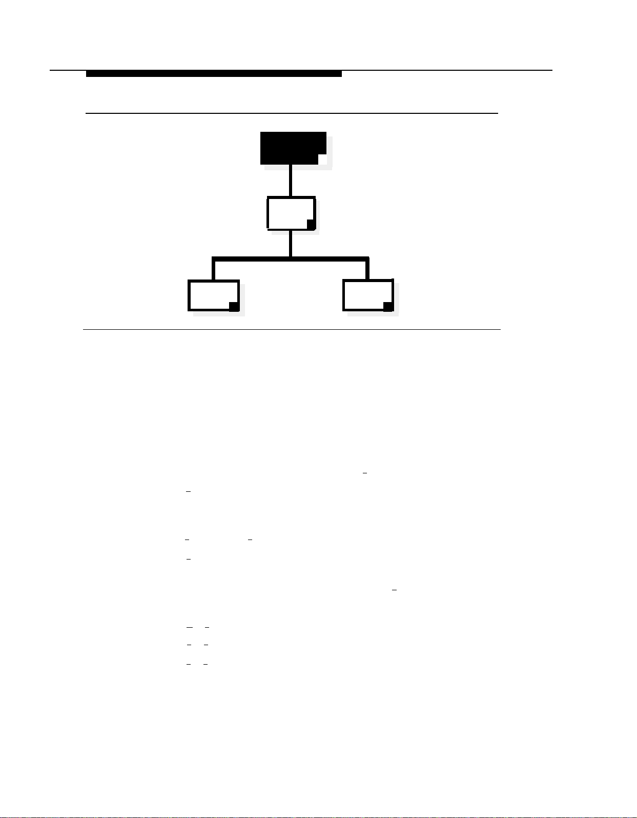
Programming the Mail System
System
Administration
Extension
System
Greetings
9
7
Voice
Mail
Greeting
1
Figure 3-7. System Greetings Administration
Recording Touch-Tone Gate Greetings
This procedure applies only if the Touch-Tone Gate is On. If the Touch-Tone
Gate is Off, skip to “Recording a Voice Mail Greeting.”
Use this procedure to record the Day and Night greetings that callers hear
when an Automated Attendant answers as specified on mail system Planning
Form E. For more information, see Greetings (System) in Chapter 5.
From the System Administration Menu, press [
1.
Press [
2.
Multiple Automated Attendant only: Enter the Automated Attendant
3.
number.
Press [
4.
Press [ 1 ] to record. For better sound quality, be sure to use the handset
5.
rather than the speakerphone to record the greeting.
3 ] for Automated Attendant Touch-Tone Gate Greeting.
1
] for Day or [ 2 ] for Night.
Touch-Tone
Gate
Greeting
3
7 ] for System Greetings.
3-24
6.
Record the greeting (up to two minutes), then press [
Press one of the following:
7.
■
[ ★ ] [ # ] to approve. Then go to Step 8.
[ 2 ] [ 3 ] to play back. Then repeat Step 7.
■
■
2
] [ 1 ] to re-record. Then repeat from Step 6.
[
Mail System Initial Programming
1 ].
Page 64

Programming the Mail System
■
[ ★ ] [ D ] ([ ★ ] [ 3 ]) to delete the new greeting and use the previous
greeting.
8.
If you need to record another greeting for this Automated Attendant, repeat
from Step 4.
Press [ ★ ] [ # ] to quit.
9.
10.
Multiple Automated Attendant only: If you need to record greetings for
another Automated Attendant, repeat from Step 3.
Recording a Voice Mail Greeting
NOTE:
It is recommended that you use the factory setting for the Voice Mail
Greeting.
Use this procedure to record the Voice Mail Greeting that subscribers hear
when they call Voice Mail. This greeting is specified on mail system Planning
Form F. For more information, see Greetings in Chapter 5.
1.
From the System Administration Menu, press [
2.
Press [ 1 ] for Voice Mail Greeting.
3.
Press one of the following:
■
[ 1 ] to record. Then go to Step 4. For better sound quality, be sure to
use the handset rather than the speakerphone to record the greeting.
■
0 ] to listen to the greeting. Then repeat Step 3.
[
■
2 ] to use the system default greeting. Bilingual only: Repeat Step 3
[
for the secondary language.
■
[ ★ ] [ # ] to use the current greeting. Bilingual only: Repeat Step 3 for
the secondary language.
Record the greeting (up to two minutes), then press [
4.
5.
Press one of the following:
■
[ ★ ] [ # ] to approve. Bilingual only: Repeat Steps 3 through 5 for the
secondary language.
■
[ 2 ] [ 3 ] to play back. Then repeat Steps 5.
■
2
] [ 1 ] to re-record. Then repeat from Step 4.
[
■
[ ★ ] [ D ] ([ ★ ] [ 3 ]) to delete the new greeting. Return to Step 3.
7 ] for System Greetings.
1 ].
Mail System Initial Programming
3-25
Page 65

Programming the Mail System
Programming the Automated Attendant Menus
Following is a list of the factory settings for the Automated Attendant menu
features covered in this section:
Parameter
Main Menu Prompt
Factory Setting
See Appendix D, “Day/Night
Main Menu”
Main Menu Selector Codes
Dial 0/Timeout Action
1-5 = Direct Extension Transfer
Day: Transfer to Call Answer
Service Operator
Night: Record Message in
General Mailbox
Submenus
Announcements
None
None
Check mail system Planning Forms G through K to see if you need to change
any of these settings.
■
If you do NOT, skip to “Creating Group Lists” on page 3-30.
■
If you do, continue with the procedures in this section. For these
procedures, you select the Automated Attendant option from the System
Administration Menu. The Automated Attendant Menu plays. Figure 3-6,
earlier in this chapter, shows the options available from the Automated
Attendant Menu.
Security Alert:
Automated Attendants should be programmed to give callers access only
to system extensions, mailboxes (including Bulletin Boards), submenus,
and announcements.
3-26
You must program Announcements and Submenus before you program
the higher-level menu options that select them. Therefore, record all
Announcements first. Then create Submenus, starting with the lowestlevel Submenu and continuing up the Submenu levels so that the Main
Menus are the last ones programmed. To help you, reorganize the mail
system Planning Forms in the following order:
■
Form K, Announcements
■
Form J, Submenu Definition
■
Form I, Submenu Prompt
■
Form H, Main Menu Definition
■
Form G, Main Menu Prompt
Mail System Initial Programming
Page 66

Programming the Mail System
Recording Announcements
Use this procedure to record Announcements that callers hear when they select
them from Automated Attendant menus. Announcements are specified on mail
system Planning Form K. For more information, see Announcements
(Automated Attendant) in Chapter 5.
From the System Administration Menu, press [
1.
Multiple Automated Attendant only: Enter the Automated Attendant
2.
3 ] for Automated Attendant.
number.
4
Press [
3.
4.
Press [
Enter an Announcement Number + [
5.
Press [ 9 ] to approve that you want to record or [ 6 ] to cancel. For better
6.
] for Announcements.
7
] to record.
#
].
sound quality, be sure to use the handset rather than the speakerphone to
record the announcement.
7.
Record the Announcement (up to two minutes), then press [
8.
Press one of the following:
[ ★ ] [ # ] to approve. Then go to Step 9.
■
[ 2 ] [ 3 ] to play back. Then repeat Step 8.
■
■
2
] [ 1 ] to re-record. Then repeat from Step 7.
[
■
[ ★ ] [ D ] ([ ★ ] [ 3 ]) to delete the new Announcement.
1.
Bilingual only: Repeat Steps 7 and 8 for the secondary language.
If you need to record another Announcement for this Automated Attendant,
2.
1 ].
repeat from Step 4.
3.
Multiple Automated Attendant only: If you need to record Announcements
for another Automated Attendant, press [ ★ ] [ 7 ], then repeat from Step 2.
Creating Submenus
Use this procedure to create Submenus for Automated Attendants as specified
on mail system Planning Forms I and J. For more information, see Submenus
(Automated Attendant) in Chapter 5.
1.
From the System Administration Menu, press [
Multiple Automated Attendant only: Enter the Automated Attendant
2.
number.
3.
Press [ 3 ] for Submenus.
Press [
4.
4
] to create a Submenu.
3 ] for Automated Attendant.
Mail System Initial Programming
3-27
Page 67

Programming the Mail System
5.
Enter the Submenu Number + [ # ].
Enter a Selector Code.
6.
7.
Enter the corresponding Action as follows:
Selector Code Transfer:
Play Submenu:
Play Announcement:
Prompted Transfer:
Direct Extension Transfer:
or
★
] [ D ] ([ ★ ] [ 3 ]) to delete. When prompted, press [ 9 ] to approve or [ 6 ] to
[
cancel the deletion.
Repeat Steps 6 and 7 until finished programming Selector Codes.
8.
Press [ ★ ] [ # ].
9.
Record the Submenu prompt (up to two minutes), then press [ 1 ]. For better
10.
sound quality, be sure to use the handset rather than the speakerphone to
record the prompt.
Press one of the following:
11.
[ 1 ] + extension number + [ # ].
[ 2 ] + Submenu number + [ # ].
[ 3 ] + Announcement number + [ # ].
[ 4 ].
[ 5 ].
■
[ ★ ] [ # ] to approve. Then go to Step 12.
■
[ 2 ] [ 3 ] to play back. Then repeat Step 11.
■
[ 2 ] [ 1 ] to re-record. Then repeat from Step 10.
■
[ ★ ] [ D ] ([ ★ ] [ 3 ]) to delete the new Submenu prompt.
1.
Bilingual only: Repeat Steps 10 and 11 for the secondary language.
If you need to record another Submenu for this Automated Attendant,
2.
repeat from Step 4.
Multiple Automated Attendant only: If you need to create Submenus for
3.
another Automated Attendant, press [ ★ ] [ 7 ]. Then repeat from Step 2.
Programming Day and Night Menus
Use this procedure to program the Day and Night Main Menus that callers hear
when an Automated Attendant answers a call. Main Menu information is
specified on mail system Planning Forms G and H. Remember that, even if the
Night Main Menu is identical to the Day Main Menu, you must program both
menus. For more information, see Main Menus (Automated Attendant) in
Chapter 5.
From the System Administration Menu, press [ 3 ] for Automated Attendant.
1.
2.
Multiple Automated Attendant only: Enter the Automated Attendant
number.
3-28
Mail System Initial Programming
Page 68

Programming the Mail System
3.
Press [ 1 ] for day; if you do not need to record a Day Menu, skip to Step 16.
4.
Press [ 6 ] to modify the menu.
5.
Enter a Selector Code.
6.
If prompted, press [
Enter the corresponding Action as follows:
7.
9 ] to approve, or [ 6 ] to cancel and return to Step 5.
Selector Code Transfer:
Play Submenu:
Play Announcement:
Prompted Transfer:
Direct Extension Transfer:
[ 1 ] + extension number + [ # ].
2
] + Submenu number + [ # ].
[
3
] + Announcement number + [ # ].
[
[ 4 ].
[ 5 ].
or
[ ★ ] [ D ] ([ ★ ] [ 3 ]) to delete. When prompted, press [ 9 ] to approve or [ 6 ] to
cancel the deletion.
Repeat Steps 5 through 7 until finished programming Selector Codes.
8.
9.
Press [ ★ ] [ # ].
10.
Choose the Dial 0/Timeout Action:
Transfer to Call Answer Service Operator
Record Message In General Mailbox
Disconnect
Transfer to Extension
Quit (keep current setting)
Enter the extension number + [ # ].
11.
Choose one of the following:
12.
Press [ # ] to use the existing prompt.
■
[ 0 ]. Go to Step 12.
[ 1 ]. Go to Step 12.
[ 2 ]. Go to Step 12.
[ 3 ]. Go to Step 11.
[ ★ ] [ # ]. Go to Step 12.
■
Record a new prompt, then press [ 1 ]. For better sound quality, be
sure to use the handset rather than the speakerphone to record the
prompt.
Press one of the following:
13.
[ ★ ] [ # ] to approve. Then go to Step 14.
■
■
2
] [ 3 ] to play back. Then repeat Step 13.
[
■
2
] [ 1 ] to re-record. Then repeat from Step 12.
[
■
[ ★ ] [ D ] ([ ★ ] [ 3 ]) to delete the new prompt.
Bilingual only: Repeat Steps 12 and 13 for the secondary language.
14.
Mail System Initial Programming
3-29
Page 69
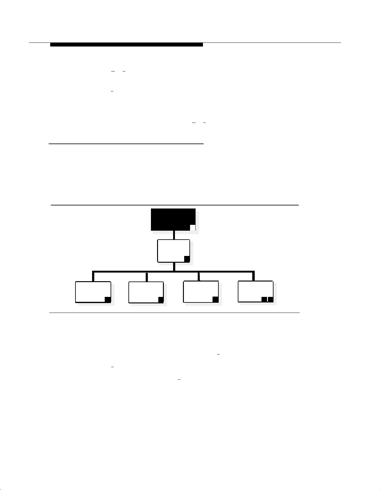
Programming the Mail System
15.
Press [ ★ ] [ # ] to program the Night Main Menu and continue with Step 16;
otherwise, skip to Step 18.
Press [ 2 ] for Night.
16.
Repeat Steps 4 through 14 for the Night Main Menu.
17.
Multiple Automated Attendant only: If you need to program Main Menus for
18.
another Automated Attendant, press [ ★ ] [ 7 ]. Then repeat from Step 2.
Creating Group Lists
Check mail system Planning Form L to see if you need to create Group Lists.
■
If you do NOT, skip to “Assigning Line Ownership” on page 3-31.
■
If you do, continue with the procedure in this section. For this procedure,
you select the Group Lists option from the System Administration Menu.
The Group Lists Menu plays. Figure 3-8 shows the options available from
the Group Lists Menu.
System
Administration
Menu
9
Scan
Group Lists
2
Create a
Group List
Figure 3-8. Group Lists Administration
Use this procedure to create Group Lists as specified on mail system Planning
Form L. For more information, see Group Lists in Chapter 5.
From the System Administration Menu, press [ 5 ] for Group Lists.
1.
Press [ 4 ] to create a Group List.
2.
3.
Enter the Group List Number + [ # ].
Group
Lists
5
Modify or
Review a
4 6
Group List
Delete a
Group List
✳ D
3-30
Mail System Initial Programming
Page 70

Programming the Mail System
Enter the Mailbox No. + [ # ].
4.
NOTE:
If you make a mistake, press [ ★ ] [ D ] ([ ★ ] [ 3 ]) to delete the entry. Then
enter the mailbox you want.
5.
Repeat Step 4 until finished.
6.
Press [ ★ ] [ # ] to quit.
7.
If you need to create another Group List, repeat from Step 2.
Assigning Line Ownership
Check mail system Planning Form M to see if you need to assign Line
Ownership.
■
If you do NOT, skip to “Setting System Security Options” on page 3-32.
■
If you do, continue with the procedure in this section. For this procedure,
you select the Line Ownership option from the System Administration
Menu. The Line Ownership Menu plays. Figure 3-9 shows the options
available from the Line Ownership Menu.
Administration
Scan
Line
Ownership
Deallocate Line
Ownership
2 ✳ 3
Figure 3-9. Line Ownership Assignment
Use this procedure to assign Line Ownership as specified on mail system
Planning Form M. If this system has Multiple Automated Attendants, each
VMS-Mail line for which Group Call Distribution (#206) is used to assign Voice
Mail coverage (VMS Line Cover) should be assigned Line Ownership. Lines not
assigned ownership will be directed to Automated Attendant 1’s General
Mailbox. For more information, see Line Ownership in Chapter 5.
System
Menu
Line
Ownership
9
6
Assign
Line
Ownership
Modify
Line
Ownership
4
6
Mail System Initial Programming
3-31
Page 71

Programming the Mail System
From the System Administration Menu, press [
1.
Press [ 4 ] to assign Line Ownership.
2.
3.
Enter a Line No. + [
4.
Enter the Line Owner’s Extension + [
Repeat Steps 3 and 4 until finished.
5.
Press [ ★ ] [ # ] to quit.
6.
#
Setting System Security Options
Security options include Minimum Password Length and Security Violation
Notification. There are factory settings for both options. Check mail system
Planning Form N to see if you need to change the setting for either option.
■
If you do NOT, skip to “After Initial Programming” on page 3-34.
■
If you do, continue with the procedures in this section. For these
procedures, you select the System Security option from the System
Administration Menu. The System Security Menu plays. Figure 3-10
shows the options available from the System Security Menu.
].
6 ] for Line Ownership.
#
].
System
Administration
Menu
System
Security
Minimum
Password
Length
2
Security
Violation
Notification
Figure 3-10. System Security Administration
9
8
System
Administration
3 4
Password
3-32
Mail System Initial Programming
Page 72

Programming the Mail System
Minimum Password Length
Security Alert:
A minimum password length of at least six digits is strongly
recommended. The shorter the minimum pass word length, the more
vulnerable your system is to abuse by unauthorized persons. Choose the
largest acceptable minimum length in order to maximize the security of
your system.
Use this procedure to set the minimum number of digits in user passwords as
specified on mail system Planning Form N. For more information, see
Passwords in Chapter 5.
From the System Administration Menu, press [
1.
Press [ 2 ] for Password Length.
2.
Enter the minimum number of digits required for a password + [
3.
Security Violation Notification
Security Alert:
The System Administrator should use the most restrictive form of the
feature that the business allows. Use the Mailbox Lock option unless this
would be too restrictive for the business. Use the Warning Message
option otherwise. The System Administrator should investigate all warning
messages received. Programming a system without Security Violation
Notification is strongly discouraged.
Use this procedure to select the action to be taken after unsuccessful attempts
to log in to a mailbox, and to specify the number of attempts permitted before
the action occurs as specified on mail system Planning Form N. For more
information, see Security Violation Notification in Chapter 5.
From the System Administration Menu, press [
1.
Press [ 3 ] for Security Violation Notification.
2.
3.
Press one of the following:
8 ] for System Security.
# ].
8 ] for System Security.
■
[ 1 ] for Mailbox Lock. Continue with Step 4.
■
[ 2 ] for Warning Message. Continue with Step 4.
■ [ 3 ] for No Security Violation Notification. The procedure is complete.
Enter the maximum consecutive unsuccessful login attempts allowed + [
4.
Mail system initial programming is complete. Continue with “After Initial
Programming.”
Mail System Initial Programming
# ].
3-33
Page 73

After Initial Programming
After Initial Programming
When initial programming is completed, notify the System Administrator of the
passwords you have assigned. Then work with the System Administrator to
change the passwords, using the following procedures.
Security Alert:
It is strongly recommended that the System Administrator change the
System Administrator’s mailbox password and the System Administration
Password after initial programming is complete.
Assigning the System Administrator’s Mailbox Password
The System Administrator should perform the following procedure:
Log in to the System Administrator’s mailbox.
1.
Press [
Intercom
a.
Enter the System Administrator’s mailbox number + [ # ].
b.
] [ 7 ] [ 7 ] [ 7 ].
Enter the System Administrator’s mailbox password + [
c.
Press [ 5 ] to change the password.
2.
Enter a new password + [
3.
# ]. For system security, make the password a
difficult-to-guess value.
Re-enter the new password + [ # ].
4.
This new password must be used in the future to log in to the System
Administrator’s mailbox.
Assigning a System Administration Password
The System Administrator should perform the following procedure:
Log in to System Administration.
1.
a.
Press [
Intercom
] [ 7 ] [ 7 ] [ 7 ].
Enter the System Administrator’s mailbox number + [ # ].
b.
Enter the System Administrator’s mailbox password, as assigned in
c.
the procedure above, + [
Press [ 9 ] for System Administration.
d.
# ].
# ].
3-34
Enter the System Administration password + [ # ].
e.
Mail System Initial Programming
Page 74

After Initial Programming
2.
Press [
8
] for System Security.
3.
Press [
Enter a new password + [ # ]. This password must be different from the
4.
4
] for System Administration Password.
System Administrator’s mailbox password. For system security, make the
password a difficult-to-guess value.
Re-enter the new password + [ # ].
5.
This new password must be used in the future to access System Administration.
Mail System Initial Programming
3-35
Page 75

Communications System
Initial Programming
Introduction
Before You Begin
Entering Programming Mode
Automated Attendant Service
■
Group Call Distribution
■
VMS Hunt Delay
■
Fax Machine Extensions
■
Fax Hunt Group
■
Line Ringing
■
Automatic Extension Privacy
■
VMS Hunt Schedule
■
Night Service
■
Music on Hold
Disallowed Phone Numbers
■
Creating a Disallowed List
Assigning the Disallowed Phone Number List
■
Allowed Phone Numbers
Creating an Allowed Phone Number List
Assigning the Allowed Phone Number List
Call Answer Service
Line Coverage
■
VMS Line Cover
Line Coverage Extension (Communications System Release
4.0 or later)
■
Automatic VMS Cover
4-1
4-1
4-2
4-2
4-2
4-2
4-3
4-3
4-3
4-4
4-4
4-5
4-5
4-6
4-6
4-6
4-7
4-7
4-7
4-8
4-8
4-8
4-8
4-9
Communications System Initial Programming
4-i
Page 76

Contents
■
■
Telephone Button Programming
■
■
■
■
After Initial Programming
VMS Cover Rings (Communications System Release 4.0 or
later)
Exiting Programming Mode
VMS Cover
Do Not Disturb
Voice Mailbox Transfer
Voice Mail Messages
4-9
4-9
4-10
4-10
4-10
4-11
4-11
4-12
4-ii
Communications System Initial Programming
Page 77

Communications System Initial Programming
Introduction
This chapter contains procedures for communications system features that must be
programmed for proper operation of the mail system. This information assumes that
communications system forms have been completed and that you are familiar with
communications system programming.
For information about communications system forms, refer to Appendix B. For
information about communications system programming and features, refer to the
Programming and Use guide for the communications system.
References to forms throughout this chapter are based on communications system
Release 4.1 forms. The terminology and page numbers may vary slightly on forms for
other releases of the communications system.
The procedures in this chapter assume that this is the first time a mail system is
being installed on an existing communications system. If this is not the case, some of
the communications system’s settings may already be changed to the values
specified here. It is recommended that you perform each procedure and verify all of
the settings.
Before You Begin
Before you begin, locate communications system Planning Forms A, B1, B2, C and
D.
Communications System Initial Programming
4-1
Page 78

Entering Programming Mode
Entering Programming Mode
To enter programming mode, at extension 10 or 11, press
[
Feature
] [ 0 ] [ 0 ] [
System Program
] [
System Program
Automated Attendant Service
Check communications system Planning Form A, Page 1, Line Coverage, to see if
any lines are checked for VMS-AA. If so, use the procedures in this section to
program Automated Attendant Service; otherwise, skip to “Call Answer Service” on
page 4-8.
Group Call Distribution
Use this procedure to specify the outside lines on which Automated Attendant
Service is required.
].
To assign VMS-AA lines specified on communications system Planning Form A, Page
1,
Line Coverage, to Hunt Group 7:
Press [ # ] [ 2 ] [ 0 ] [ 6 ].
1.
At the
2.
At the
3.
Press [
4.
To program another line, press [
5.
number displays.
Press [
6.
Repeat Steps 6 and 7 for each VMS-AA line on Form A.
7.
VMS Hunt Delay
Check communications system Planning Form A, Page 2, VMS Hunt Delay. If
Delayed (Del) is specified, follow the procedure below. Otherwise, skip to the next
section, “Fax Machine Extensions.”
To change the VMS Hunt Delay setting from Immediate to Delayed as specified on
Form A, Page 2:
Group:
Line:
Next Data
Next Data
prompt, press [ 7 ].
prompt, enter the first VMS-AA line.
] until the display reads
] until the display reads
1 Assigned.
Next Item
] or [
1 Assigned.
Prev Item
] until the appropriate line
Press [ # ] [ 5 ] [ 0 ] [ 6 ].
1.
Press [
2.
4-2
Communications System Initial Programming
Next Data
] until the appropriate value displays.
Page 79

Automated Attendant Service
Fax Machine Extensions
To assign Fax Machine Extensions specified on communications system Planning
Form B1:
Press [ # ] [ 6 ] [ 0 ] [ 1 ].
1.
At the
2.
Extension:
connected.
prompt, enter the extension to which the fax machine is
Press [
3.
To identify another extension, press [
4.
number shows on the display. Then repeat Step 3.
Fax Hunt Group
Check communications system Planning Form B2 to see if a Hunt Group of fax
machines is desired. If so, follow the procedure below. If not, skip to the next section,
“Line Ringing.”
To create a fax Hunt Group:
Press [ # ] [ 5 ] [ 0 ] [ 5 ].
1.
At the Group: prompt, enter the group number.
2.
Enter the number of the first extension to be assigned to the group.
3.
Press [
4.
To assign another extension, press [
5.
shows on the display.
Press [
6.
Repeat Steps 5 and 6 for each extension to be assigned to the group.
7.
Next Data
Next Data
Next Data
] until the display reads
Next Item
] until the display reads
Next Item
] until the display reads
1 Assigned.
] or [
Prev Item
1 Assigned.
] or [
Prev Item
1 Assigned.
] until the extension
] until the extension number
Line Ringing
For Fax Machine Extensions or extensions in a fax Hunt Group, change the Line
Ringing setting to No Ring. Otherwise, skip to the next section, “Automatic Extension
Privacy.”
To change the line ringing setting:
1.
2.
Press [
Central Tel Program
].
Enter the extension number to be programmed. The green lights next to the line
buttons show the current Line Ringing settings for all lines assigned to the
extension. (If a line is not assigned to a button, the green light next to the button is
Off.) The ringing options are as follows:
■ Immediate Ring
■
Delayed Ring
■ No Ring
— green light flutters quickly
—green light on steady
—green light flashes slowly
Communications System Initial Programming
4-3
Page 80

Automated Attendant Service
3.
Press each line button until the green light signifies No Ring.
4.
Press [
Central Tel Program
5.
Repeat Steps 2 through 4 for each extension to be programmed.
6.
When you are finished, press [
Automatic Extension Privacy
If VMS Hunt Delay is set to Immediate, use this procedure to prevent subscribers
from accidentally picking up calls sent to the mail system. Also use this procedure for
all Fax Machine Extensions and all extensions assigned to a fax Hunt Group.
To set Automatic Extension Privacy (#304) to Assigned for the PARTNER MAIL
extensions and the Fax Machine Extensions specified on communications system
Planning Form B1, as well as all extensions assigned to a fax Hunt Group on
communications system Planning Form B2:
Press [ # ] [ 3 ] [ 0 ] [ 4 ].
1.
].
Central Tel Program
], then [
System Program
].
Enter the first PARTNER MAIL extension number specified on Form B1.
2.
3.
4.
Press [
Press [
Next Data
Next Item
displays.
Press [
5.
If additional PARTNER MAIL extensions are specified, repeat Steps 4 and 5 for
6.
Next Data
each one.
If Fax Machine Extensions are specified on Form B1, repeat Steps 4 and 5 for
7.
each one.
If extensions are assigned to a fax Hunt Group on Form B2, repeat Steps 4 and 5
8.
for each extension.
VMS Hunt Schedule
Check communications system Planning Form A, Page 2, VMS Hunt Schedule. If
either Day Only or Night Only is selected, follow the procedure below. Otherwise,
skip to the next section, “Night Service.”
To change the VMS Hunt Schedule setting as specified on communications system
Planning Form A, Page 2:
] until the display reads
] or [
Prev Item
] until the next PARTNER MAIL extension number
] until the display reads
1 Assigned.
1 Assigned.
Press [ # ] [ 5 ] [ 0 ] [ 7 ].
1.
Press [
2.
4-4
Communications System Initial Programming
Next Data
] until the appropriate value appears.
Page 81

Automated Attendant Service
Night Service
Check communications system Planning Form C for extension 10. If a Night Service
button is specified, follow the procedure below.
To program Night Service on a button with lights at extension 10 as specified on
Form C:
1.
Press [ # ] [ 5 ] [ 0 ] [ 3 ].
At this point, do one of the following:
2.
If you want to assign Night Service to the first available button on the
■
system phone, press [
■
If you want to assign Night Service to a specific button, press [ 3 ]. The
display reads:
Next Data
] until the display reads:
Night Service
1 Assigned-Ext10
Night Service
3 Select Button
3.
Label the Night Service button at extension 10.
Music on Hold
The Music on Hold feature activates or deactivates the Music on Hold jack on the
primary processor module. The jack must be active and an audio source must be
connected to the jack in order to provide recorded music or messages to callers on
hold. It is strongly recommended that Music on Hold be used for communications
systems prior to Release 4.1.
Check communications system Planning Form A, Page 2, Music on Hold, to see if the
Music on Hold jack is active. If so, follow the procedure below. Otherwise, skip to the
next section, “Disallowed Phone Numbers.”
To activate the Music on Hold jack:
Press [ # ] [ 6 ] [ 0 ] [ 2 ].
1.
2.
Press [
Press the desired programmable button with lights to assign Night Service
to that button.
Next Data
] until the appropriate value displays.
Communications System Initial Programming
4-5
Page 82

Automated Attendant Service
Disallowed Phone Numbers
If Outcalling is permitted, a Disallowed Phone Number List (#404) can be created to
restrict calls.
Creating a Disallowed List
Check communications system Planning Form D to see if a Disallowed Phone
Number List is needed for Outcalling. If so, continue with the procedures in this
section; otherwise, skip to “Allowed Phone Numbers.”
To create a list of Disallowed Phone Numbers:
1.
Press [ # ] [ 4 ] [ 0 ] [ 4 ].
At the
2.
List Number:
prompt, enter the list number (1–4).
3.
4.
5.
6.
■
Entry:
At the
Data---------------
At the
To save the number in memory,
prompt, select a list entry (01–10).
prompt, enter the first number.
you must press [
At this point:
To change the number you just entered, press [ Remove ] and repeat Steps 4 and
5.
■
To delete the number you just entered, press [
■
To enter other numbers in this list, press [ Next Item ] and repeat Steps 4 and 5.
Assigning the Disallowed Phone Number List
The Disallowed Phone Number List that was created for Outcalling should be
assigned to the extension(s) that are connected to the Outcalling port(s)—port 2 on a
two-port system, port 4 on a four-port system, or ports 5 and 6 on a six-port system.
To assign the Disallowed Phone Number List to the extensions:
1.
Press [ # ] [ 4 ] [ 0 ] [ 5 ].
Enter the number of the extension to be programmed.
2.
3.
Enter the list number (1-4).
Enter
Remove
].
].
To assign the list, press [
4.
5.
To program another extension, press [
Step 2.
4-6
Communications System Initial Programming
Next Data
] until the display reads
Next Procedure
] [
Prev Procedure
1 Assigned.
] and repeat from
Page 83

Automated Attendant Service
Allowed Phone Numbers
If Outcalling is permitted, an Allowed Phone Number List (#407) can be created to
identify numbers to which Outcalling is allowed.
NOTE:
If the PARTNER MAIL extensions were restricted to Inside Only using
Outgoing Call Restriction (#401), Outcalling will not work unless an Allowed
Phone Number List is created and assigned. Outcalls can be made only to
the numbers included in the list.
Creating an Allowed Phone Number List
Check communications system Planning Form D to see if an Allowed Phone Number
List is needed for Outcalling. If so, continue with the procedures in this section;
otherwise, skip to “Call Answer Service” on page 4-8.
To create a list of Allowed Phone Numbers:
Press [ # ] [ 4 ] [ 0 ] [ 7 ].
1.
At the
2.
List Number:
prompt, enter the list number (1–4).
3.
4.
5.
6.
■
Entry:
At the
Data---------------
At the
prompt, select a list entry (01–10).
To save the number in memory,
At this point:
To change the number you just entered, press [ Remove ] and repeat Steps 4 and
5.
■
To delete the number you just entered, press [
■
To enter other numbers in this list, press [ Next Item ] and repeat Steps 4 and 5.
Assigning the Allowed Phone Number List
The Allowed Phone Number List that was created for Outcalling should be assigned
to the extension(s) that are connected to the Outcalling port(s)—port 2 on a two-port
system, port 4 on a four-port system, or ports 5 and 6 on a six-port system.
To assign the Allowed Phone Number List to the extensions:
1.
Press [ # ] [ 4 ] [ 0 ] [ 8 ].
2.
Enter the number of the extension to be programmed.
Enter the list number (1–4).
3.
prompt, enter the first number.
you must press [
Enter
Remove
].
].
4.
To assign the list, press [
To program another extension, press [
5.
Next Data
Step 2.
Communications System Initial Programming
] until the display reads
Next Procedure
] [
Prev Procedure
1 Assigned.
] and repeat from
4-7
Page 84

Call Answer Service
Call Answer Service
Before you begin, locate communications system Planning Forms A and B2.
Line Coverage
Check communications system Planning Form A, Page 1, Line Coverage, VMS-Mail:
■
If check marks appear for any lines in this column, use the procedure in “VMS
Line Cover,” below.
■
For communications system Release 4.0 or later: If extension numbers are
specified for any lines in this column, use the procedure in “Line Coverage
Extension (Communications System Release 4.0 or later)” below.
■
If there are no entries in this column, skip to “Automatic VMS Cover” on
page 4-9.
VMS Line Cover
To assign VMS-Mail lines checked on communications system Planning Form A,
Page 1, Line Coverage, to Hunt Group 7:
Press [ # ] [ 2 ] [ 0 ] [ 6 ].
1.
2.
At the
Group:
At the
3.
4.
5.
Line:
Press [
Next Data
To program another line, press [
prompt, press [ 7 ].
prompt, enter the first line checked in the VMS-Mail column.
] until the display reads
3 VMS Line Cover.
Next Item
] or [
number displays.
Press [
6.
Repeat Steps 5 and 6 for each VMS-Mail line checked on Form A.
7.
Next Data
] until the display reads
3 VMS Line Cover.
Line Coverage Extension (Communications System Release 4.0 or later)
To assign line coverage for the extension numbers specified in the VMS-Mail column
on communications system Planning Form A, Page 1, Line Coverage:
Press [ # ] [ 2 ] [ 0 ] [ 8 ].
1.
At the Line: prompt, enter the first line for which an extension is specified.
2.
At the Data: prompt, enter the number of the extension specified in the VMS-Mail
3.
column.
Prev Item
] until the appropriate line
To program another line, press [
4.
number displays.
At the
5.
4-8
Communications System Initial Programming
Data:
prompt, enter the number of the next extension.
Next Item
] or [
Prev Item
] until the appropriate line
Page 85

Call Answer Service
6.
Repeat Steps 4 and 5 for each VMS-Mail line for which an extension number is
written in the VMS-Mail column.
Automatic VMS Cover
Check communications system Planning Form B2 to see if Automatic VMS Cover is
assigned to any extensions. If it is, follow the procedure below. If not, skip to “VMS
Cover Rings.”
To change the Automatic VMS Cover setting for an extension to Assigned as
indicated on Form B2:
Press [ # ] [ 3 ] [ 1 ] [ 0 ].
1.
Enter the number of the first extension to which Automatic VMS Cover is to be
2.
assigned.
Press [
3.
To program another extension, press [
4.
Next Data
] until the display reads
1 Assigned.
Next Item
number shows on the display.
Press [
5.
Repeat Steps 4 and 5 for each extension to which Automatic VMS Cover is to be
6.
Next Data
] until the display reads
1 Assigned.
assigned.
VMS Cover Rings (Communications System Release
4.0 or later)
Check communications system Planning Form A, Page 2, to see if VMS Cover Rings
(#117) is different from the factory setting of 3. If it is, follow the procedure below. If
not, skip to “Exiting Programming Mode.”
To change the number of times calls ring before they are sent to the mail system as
indicated on Form A, Page 2, VMS Cover Rings:
1.
Press [ # ] [ 1 ] [ 1 ] [ 7 ].
2.
Enter the VMS Cover Rings setting.
Exiting Programming Mode
] or [
Prev Item
] until the extension
To exit programming mode, press [
Feature
Communications System Initial Programming
] [ 0 ] [ 0 ].
4-9
Page 86

Telephone Button Programming
Telephone Button Programming
Before you begin, locate communications system Planning Form C. Be sure you have
a version of the form for each subscriber’s phone.
Use this section to program buttons on subscribers’ phones, including the
receptionist’s phone. This section uses Centralized Telephone Programming.
When you are finished programming, be sure to label all buttons on subscribers’
phones.
VMS Cover
This button enables the subscriber to turn voice mail coverage On and Off.
To program a VMS Cover button as specified on communication system Planning
Form C:
1.
Press [
Feature
] [ 0 ] [ 0 ] [
System Program
] [
System Program
] [
Central Tel Program
].
Enter the number of the extension to be programmed.
2.
Press a programmable button with lights.
3.
4.
Press [
At this point, do one of the following:
5.
Do Not Disturb
This button can be used to prevent calls for the extensions from audibly alerting
(lights still flash). For communications system Release 4.0 or later, Do Not Disturb
can be used in conjunction with either Automatic VMS Cover or manual VMS Cover to
enable the subscriber to send callers immediately to his or her mailbox (without
ringing the extension first).
To program a Do Not Disturb (DND) button as specified on communications system
Planning Form C:
Feature
] [ 1 ] [ 5 ].
■
Go to Step 3 of the next procedure to program another button for this
extension.
■
Press [
Central Tel Program
] and go to Step 2 of any button programming
procedure in this section to program a button for a different extension.
Press [
Feature
■
] [ 0 ] [ 0 ] to exit.
4-10
Press [
Feature
Feature
] [ 0 ] [ 0 ] [
] [ 0 ] [ 1 ].
1.
Enter the number of the extension to be programmed.
2.
Press a programmable button with lights.
3.
Press [
4.
System Program
] [
System Program
Communications System Initial Programming
] [
Central Tel Program
].
Page 87

Telephone Button Programming
At this point, do one of the following:
5.
■
Go to Step 3 of the next procedure to program another button for this
extension.
■
Press [
procedure in this section to program a button for a different extension.
■
Press [
Voice Mailbox Transfer
This button enables any system user to transfer calls to a subscriber’s mailbox,
without ringing the extension first.
To program a Voice Mailbox Transfer (VMBox) button as specified on
communications system Planning Form C:
Press [
1.
2.
3.
4.
5.
Feature
Enter the number of the extension to be programmed.
Press a programmable button.
Press [
Feature
At this point, do one of the following:
■
Go to Step 3 of the next procedure to program another button for this
extension.
Press [
■
procedure in this section to program a button for a different extension.
Central Tel Program
Feature
] [ 0 ] [ 0 ] to exit.
] [ 0 ] [ 0 ] [
System Program
] [ 1 ] [ 4 ].
Central Tel Program
] and go to Step 2 of any button programming
] [
System Program
] [
Central Tel Program
].
] and go to Step 2 of any button programming
■
Press [
Voice Mail Messages
This intercom Auto Dial button enables the subscriber to access the mail system with
the touch of one button.
To program a Voice Mail Messages (VMMsgs) button as specified on
communications system Planning Form C:
Press [
1.
2.
3.
4.
5.
Feature
Enter the number of the extension to be programmed.
Press a programmable button.
Press left [
Press [
Feature
Feature
] [ 0 ] [ 0 ] to exit.
] [ 0 ] [ 0 ] [
Intercom
System Program
] [ 7 ] [ 7 ] [ 7 ].
] [ 0 ] [ 0 ] to exit.
] [
System Program
] [
Central Tel Program
].
Communications System Initial Programming
4-11
Page 88

After Initial Programming
After Initial Programming
When initial programming for the mail system and communications system is
complete, you should perform the verification tests in Chapter 6.
4-12
Communications System Initial Programming
Page 89

Understanding the Mail
System Features
Contents
Administering Features
■
Logging In to Voice Mail
■
Logging In to System Administration
Announcements (Automated Attendant)
Announcement Options
■
■
Announcements and Bulletin Boards
Applications
■
■
Recording an Announcement
Playing an Existing Announcement
■
Deleting an Announcement
■
Automated Attendant Service
Broadcast Message
Broadcast Messages and Group Lists
■
Sending a Broadcast Message
■
Bulletin Board
Monolingual or Bilingual Mode
■
Bulletin Boards and Announcements
■
Dial 0 Destination
■
Other Bulletin Board Options
■
Bulletin Board Mailbox Password
■
Applications
■
Accessing a Bulletin Board Message
■
Recording or Deleting a Bulletin Board Message
■
■
Setting a Dial 0 Destination
■
Changing a Bulletin Board Mailbox Password
5-1
5-2
5-2
5-3
5-4
5-4
5-5
5-6
5-8
5-9
5-10
5-12
5-12
5-13
5-14
5-15
5-15
5-15
5-16
5-16
5-16
5-18
5-19
5-21
5-21
Understanding the Mail System Features
5-i
Page 90

Contents
Business Schedule and Temporarily Closed
Weekly Business Schedule
■
■ Temporarily Closed
Playing the Business Schedule
■
■ Creating or Changing the Weekly Business Schedule
■
Programming a Temporary Closing
Call Answer Service Operator
■
Changing the Call Answer Service Operator Extension
Dial 0/Timeout Action (Automated Attendant)
Changing a Dial 0/Timeout Action
■
Directory
Using the Directory to Reach a Subscriber
■
Using the Directory to Address a Message
■
Changing a Directory Listing
■
Fax Extension and Fax Message Receiver
Fax Extension
■
Fax Message Receiver
■
Creating a Fax Extension or Fax Message Receiver
■
Deleting a Fax Extension or Fax Message Receiver
■
General Mailbox
Changing the General Mailbox Owner’s Extension
■
Forwarding a Message from the General Mailbox
■
Greetings (Personal)
■
Monolingual or Bilingual Mode
■
Recording a Personal Greeting
Activating a Personal Greeting
■
Deleting a Personal Greeting
■
Greetings (System)
Voice Mail Greeting
■
Automated Attendant Touch-Tone Gate Greeting
■
Monolingual Mode—Touch-Tone Gate On
■
Bilingual Mode—Touch-Tone Gate On (Primary Language,
■
English; Secondary Language, Spanish)
Monolingual Mode—Touch-Tone Gate Off
■
Bilingual Mode—Touch-Tone Gate Off (Primary Language,
■
English; Secondary Language, Spanish)
Recording the Voice Mail Greeting
■
Recording a Touch-Tone Gate Greeting
■
5-22
5-23
5-23
5-24
5-25
5-27
5-30
5-31
5-32
5-33
5-36
5-37
5-37
5-37
5-38
5-38
5-38
5-40
5-41
5-43
5-44
5-45
5-48
5-49
5-49
5-51
5-51
5-53
5-53
5-54
5-54
5-54
5-55
5-55
5-56
5-58
5-ii
Understanding the Mail System Features
Page 91

Contents
Group Lists
Group Lists and Broadcast Messages
■
Creating Group Lists
■
Scanning Group Lists
■
Modifying or Reviewing a Group List
■
Deleting Group Lists
■
Sending a Message to a Group List
■
■
Forwarding a Message to a Group List
Group Mailbox Owner
Assigning or Deleting the Group Mailbox Owner
■
Language
■
Recovering from a Language Choice Error
Changing the Language Mode or the Language
■
Line Assignments
Reviewing Line Assignments
■
Adding Line Assignments
■
Removing Line Assignments
■
Line Ownership
■
Scanning Line Ownership
Assigning Line Ownership
■
■
Modifying Line Ownership
Deallocating Line Ownership
■
Mailbox
Class of Service (COS)
■
Mailbox Storage
Message Length
Greeting Length
Transfer Permitted
Mailbox Type
Outcalling Permission
■
Mailbox Language (Bilingual Mode only)
Mailbox Name
■
■
Playing a Mailbox Configuration
Creating Mailboxes
■
■
Deleting a Mailbox
■
Changing a Mailbox Name
Changing the Class of Service
■
Initializing a Mailbox Password
■
Changing the Mailbox Language Bilingual Mode Only)
■
5-60
5-61
5-62
5-62
5-63
5-64
5-65
5-66
5-67
5-68
5-70
5-71
5-72
5-73
5-74
5-74
5-75
5-77
5-78
5-79
5-80
5-81
5-82
5-83
5-84
5-85
5-85
5-85
5-85
5-87
5-87
5-88
5-91
5-92
5-94
5-94
5-96
5-96
5-97
Understanding the Mail System Features
5-iii
Page 92

Contents
Main Menus (Automated Attendant)
Menu Prompt
■
Monolingual Mode Example with Touch-Tone Gate On
Bilingual Mode Example with Touch-Tone Gate On (Primary
Language, English; Secondary Language, Spanish)
Monolingual Mode Example with Touch-Tone Gate Off
Bilingual Mode Example with Touch-Tone Gate Off (Primary
Language, English; Secondary Language, Spanish)
■
Selector Codes
Caller Options
■
Playing a Main Menu Prompt or Definition
■
Recording the Main Menu Prompt Only
■
Modifying a Day or Night Main Menu
■
Maximum Digit Length
Changing the Maximum Digit Length
■
Open or Closed for Today
Open for Today
■
Close for Today
■
Resume Regular Schedule
■
Default Temporary Closure Greetings
■
Touch-Tone Gate Off—Monolingual
Touch-Tone Gate On—Monolingual
Touch-Tone Gate Off–Bilingual
Touch-Tone Gate On—Bilingual
Programming Open or Closed for Today
■
Resuming the Regular Schedule
■
Outcalling
Outcalling List
■
Minimum Time Between Outcalling Attempts
■
Outcalling Cycles
■
Outcalling Schedule
■
Turning Outcalling On/Off
■
Reviewing the Outcalling List
■
Listening to Instructions for Outcalling
■
Creating or Changing the Outcalling List
■
Setting Up the Outcalling Schedule
■
Setting the Minimum Time Between Outcalling Attempts
■
Setting the Number of Outcalling Cycles
■
5-98
5-99
5-99
5-99
5-100
5-100
5-100
5-102
5-103
5-104
5-107
5-111
5-111
5-113
5-113
5-114
5-114
5-115
5-115
5-115
5-115
5-116
5-117
5-119
5-120
5-121
5-122
5-123
5-123
5-124
5-124
5-124
5-124
5-126
5-127
5-128
5-iv
Understanding the Mail System Features
Page 93

Contents
Passwords
System Administrator’s Passwords
■
Minimum Password Length
■
Password Cautions
■
Password Initialization
■
Initializing a Mailbox Password
■
Setting the Minimum Password Length
■
Changing the System Administration Password
■
■
Changing a Mailbox Password
Changing a Bulletin Board Mailbox Password
■
Personal Mailbox Administration
Transfer-Only Mailboxes
■
Old and New Messages
■
Mailbox Name
■
Personal Greetings
■
Personal Operator
■
Password
■
Outcalling
■
Logging In to Voice Mail
■
Recording and Sending a Message
■
Listening to Messages
■
Replying to a Message
■
Forwarding a Message
■
Recording a Mailbox Name
■
■
Recording and Activating Personal Greetings
■
Choosing a Personal Operator
Personal Operator
Applications
■
■
Administering a Personal Operator
Schedule Controller
Follow the Switch Mode
■
■
Follow the PARTNER MAIL Business Schedule
■
Setting the Schedule Controller
Security Violation Notification
■
Unsuccessful Login Attempts
■
Mailbox Unlock
Changing the Security Violation Notification
■
Single/Multiple Automated Attendant
Setting Single or Multiple Automated Attendants
■
5-129
5-129
5-130
5-130
5-130
5-131
5-131
5-132
5-132
5-133
5-134
5-134
5-135
5-135
5-135
5-135
5-135
5-136
5-136
5-137
5-139
5-140
5-141
5-143
5-143
5-143
5-144
5-144
5-145
5-146
5-146
5-147
5-148
5-149
5-150
5-150
5-151
5-152
5-154
Understanding the Mail System Features
5-v
Page 94

Contents
Submenus (Automated Attendant)
■
Selector Codes and Selector Code Actions
■
Other Submenu Options
■
Submenu Creation
■
Submenu Modification
■
Playing a Submenu Prompt or Definition
■
Creating a Submenu
■
Recording the Submenu Prompt Only
■
Modifying a Submenu
■
Deleting a Submenu
System Administrator’s Mailbox
Changing the System Administrator’s Mailbox
■
Re-assigning the System Administrator’s Mailbox
■
Changing the System Administration Password
■
■
Changing the System Administrator’s Mailbox Password
System Date and Time
■
Updating the System Date and Time
System Language
Touch-Tone Gate
Touch-Tone Gate Setting
■
■
Turning the Touch-Tone Gate On or Off
5-155
5-156
5-157
5-157
5-157
5-158
5-159
5-161
5-163
5-166
5-167
5-168
5-169
5-169
5-169
5-170
5-170
5-172
5-173
5-173
5-175
5-vi
Understanding the Mail System Features
Page 95

Understanding the Mail System Features
Administering Features
This chapter contains PARTNER MAIL features, arranged alphabetically. The
following sections are included for each feature, if appropriate:
■
At a Glance—A summary of the key information about the feature.
■
Description—A detailed description of the feature.
■
Considerations and Constraints—Things to be aware of when using the
feature.
■
Related Communications System Features—Interactions between this feature
and communications system features.
■
Related Mail System Features—Interactions between this feature and other
mail system features. Related features appear in boldface type to indicate that
they are described in greater detail elsewhere in this chapter.
■
Programming—Instructions for you, the System Administrator, explaining how
to administer the feature.
■
Procedures—Instructions for using the feature. These procedures can be used
by subscribers as well as by the System Administrator.
Features of the mail system that are available to subscribers are accessed from
the Voice Mail Activity Menu (see “Logging In to Voice Mail,” on page 5-2). The
“At a Glance” sections for those features begin with the option you choose from
the Voice Mail Activity Menu.
Features of the mail system that are used only by the System Administrator are
accessed from the System Administration Menu. The “At A Glance” sections for
those features begin with the option you choose from that menu.
Before you can perform any mail system administration tasks, you must log in to
the System Administrator’s mailbox and System Administration (see “Logging In
to System Administration,” on page 5-2). Once you have logged in to System
Administration, you can return to the System Administration Menu by pressing
[ ★ ] [ 7 ] and continue with another procedure without logging in again.
Administering Features
5-1
Page 96

Administering Features
Logging In to Voice Mail
To log in to voice mail:
1.
Press [
Intercom
] [ 7 ] [ 7 ] [ 7 ].
The Voice Mail greeting plays. The system prompts you to enter the
extension and [ # ].
2.
Enter the number of the mailbox you want to access, followed by [ # ].
The password prompt plays.
3.
Enter the mailbox password followed by [ # ].
The name of the mailbox owner plays if the name has been programmed. If
not, the extension number plays. The system announces the number of new
and old messages, then plays the Voice Mail Activity Menu.
Logging In to System Administration
To log in to System Administration:
1.
Press [
Intercom
] [ 7 ] [ 7 ] [ 7 ].
The Voice Mail greeting plays. The system prompts you to enter the
extension and [ # ].
2.
Enter the System Administrator’s extension followed by [
#
].
NOTE:
The factory setting for the System Administrator’s extension is
[ 9 ] [ 9 ] [ 9 ] [ 7 ].
This extension may have been changed when the mail system was
installed. If it was not changed from the factory setting, you should do
so now. See “Re-assigning the System Administrator’s Mailbox” under
System Administrator’s Mailbox for instructions.
The password prompt plays.
Enter the System Administrator’s mailbox password followed by [
3.
# ].
The System Administrator’s name plays. The system announces the number
of new and old messages, then plays the Voice Mail Activity Menu.
4.
Press [ 9 ] for System Administration.
NOTE:
This option is not heard on the Voice Mail Activity Menu.
The system prompts you to enter the password and [
5.
Enter the System Administration Password followed by [ # ].
# ].
The system plays the security message, then the System Administration
Menu.
5-2
Administering Features
Page 97

Announcements (Automated Attendant)
Announcements (Automated Attendant)
At a Glance
System Administration Menu
Programmable by
Caller Options
Hear Announcement again
Play Automated Attendant
Main Menu
Play previous menu
Dial 0/Timeout Action
Transfer to another extension
Play Announcement in
alternate language (Bilingual
mode only)
Capacities
Announcement Length
Maximum Number of
Announcements
3 ] Automated Attendant
[
[ 4 ] Announcements
[
2
] Play Announcement
[
7
] Record Announcement
[ ★ ] [ D ] ([ ★ ] [ 3 ]) Delete Announcement
System Administrator
[ ★ ] [ 4 ]
[ ★ ] [ 7 ]
[ ★ ] [ # ]
[ 0 ]
[ ★ ] [ T ] ([ ★ ] [ 8 ])
[ ★ ] [ 1 ]
Up to two minutes each
99
Selector Code Action
Mail System Planning Form
Description
Announcements are recordings of up to two minutes in length that are included as
options on Automated Attendant Main Menus and Submenus. If the system is in
bilingual mode, each Announcement consists of one recording in each language.
Announcements can be programmed only by you, the System Administrator. To
program an Announcement, you must first record it. Then you can include it in Main
Menu and Submenu definitions by assigning it a Selector Code and Action 3.
You can record up to 99 Announcements. You can include the same Announcement
as an option on more than one menu.
[ 3 ] Play an Announcement
K
Announcements (Automated Attendant)
5-3
Page 98

Announcements (Automated Attendant)
Announcement Options
A caller plays an Announcement by selecting its Selector Code from a Main Menu or
Submenu. The call is disconnected four seconds after the Announcement finishes
playing unless the caller presses one of the following:
[ ★ ] [ 4 ]
[ ★ ] [ 7 ]
[ ★ ] [ # ]
[ 0 ]
[ ★ ] [ T ]
[ ★ ] [ 1 ]
Hear the Announcement again.
Play the Automated Attendant Main Menu.
Play the previous menu.
Perform the Automated Attendant’s Dial 0/Timeout Action.
([ ★ ] [ 8 ]) Transfer to another extension.
Play the Announcement in the alternate language (bilingual mode only).
Announcements and Bulletin Boards
Announcements are similar in function to Bulletin Board messages, but have some
significant differences as follows:
■
Announcements can be up to two minutes long. Bulletin Board messages can
be up to four minutes long.
■
Announcements must be created before they can be assigned to a Main Menu
or Submenu. Bulletin Board messages can be created any time.
■
An Announcement can be changed only by the System Administrator. A
Bulletin Board message is changed by the Bulletin Board mailbox owner.
■
Announcements can be accessed only from Automated Attendant Service
menus. Bulletin Board messages can be accessed from Voice Mail Service or
Call Answer Service, as well as from Automated Attendant Service.
■
Pressing [
finishes playing takes you to the Dial 0/Timeout Action destination specified
for the Automated Attendant Main Menu from which the Announcement was
accessed. Each Bulletin Board can have its own Dial 0 Destination.
■
Pressing [ ★ ] [ 7 ] while listening to an Announcement takes you to the Main Menu
for the Automated Attendant. Pressing [
message takes you back to the Voice Mail Greeting.
0 ] while listening to an Announcement or within four seconds after it
★
] [ 7 ] while listening to a Bulletin Board
Security Alert:
For security reasons, it is unwise to allow more than one person to access
System Administration. Therefore, if someone other than you will be changing
informational messages, consider using Bulletin Board messages instead of
Announcements.
5-4
Announcements (Automated Attendant)
Page 99

Announcements (Automated Attendant)
Applications
Announcements can provide callers with frequently requested information.
For example, an Announcement could describe quarterly profits for your corporation
for stockholders:
“Zippy Electronics has posted a $1.1 million profit for the third quarter.
This is due primarily to a 5% increase in sales of Zip-Widgets and cost-
cutting measures implemented on a company-wide basis. To hear this
Announcement again, press [ ★ ] [ 4 ]. To play the previous menu, press
[ ★ ] [ # ]. To transfer to another extension press [ ★ ] [ T ].”
Or an Announcement could provide information about annual awards:
“The winners of the Martin Kruskel award for excellence in actuarial skills
are Joe Smith, Fred Martinez, and Sally Jackson. We congratulate them on
their fine work. To return to the Main Menu, press [ ★ ] [ 7 ]. To reach the
operator, press [ 0 ].”
Or an Announcement could provide directions to your office:
“Our offices are located at 400 Route 9 North in Eastview, just one mile
north of the intersection of Routes 9 and 18. To repeat these directions,
press [ ★ ] [ 4 ]. If you need additional assistance, press [ 0 ] to speak to our
receptionist. To return to the Main Menu, press [
Related Mail System Features
■
In some cases, a Bulletin Board message may be more appropriate to your
needs than an Announcement. See “Announcements and Bulletin Boards” on
page 5-4 for a comparison.
■
If you change the Language mode (bilingual or monolingual), you do not need
to re-record the Announcements.
■
If you delete an Announcement, it is automatically removed from the menu
definition for all Main Menus (Automated Attendant) and Submenus
(Automated Attendant) to which it is assigned. You must re-record all menu
prompts that are affected.
★
] [ 7 ].”
Announcements (Automated Attendant)
5-5
Page 100

Announcements (Automated Attendant)
Programming
Recording an Announcement
Before recording an Announcement, complete mail system Planning Form K.
Include in the Announcement the information about how to access options ([ ★ ] [ 4 ],
[ ★ ] [ 7 ], [ ★ ] [ # ], [ 0 ], [ ★ ] [ T ] ([ ★ ] [ 8 ]), and [ ★ ] [ 1 ]) if callers can use these options. If the
system is in bilingual mode, record the Announcement in both the primary and the
secondary language.
Step 1
Step 2
Step 3
Step 4
Step 5
Step 6
Step 7
Step 8
Step 9
Action
Log in to the mail system as the System
Administrator.
Press [ 9 ] for System Administration.
Enter System Administration
Password + [ # ].
Press [
3 ] for Automated Attendant.
(Multiple Automated Attendant Only)
Enter Automated Attendant Number.
Press [ 4 ] for Announcements.
Press [
7 ] to record an Announcement.
Announcement number (1–99) + [
Choose an option:
[ 9 ] for Yes to confirm that you want to
record the Announcement.
# ].
You Hear...
Name, number of new messages and
old messages, Voice Mail Activity
Menu.
Prompt to enter the System
Administration password + [
Security message, then System
Administration Menu.
(Multiple Automated Attendant)
Prompt to enter the Automated
Attendant number.
(Single Automated Attendant)
Automated Attendant Service
Administration Menu. Go to Step 6.
Automated Attendant number, then
Automated Attendant Service
Administration Menu.
Announcement Administration Menu.
Prompt to enter the Announcement
Number.
Prompt stating whether or not the
Announcement exists, then asking
whether you want to record the
Announcement.
(Announcement does not exist)
Prompt to record at the tone.
(Announcement exists)
Prompt to record, or to use the
current Announcement.
# ].
5-6
[ 6 ] for No to cancel the recording.
[ 2 ] to play the Announcement if it
already exists.
Announcements (Automated Attendant)
Confirmation of cancellation, then the
Announcement Administration Menu.
Procedure is complete.
The Announcement. Repeat Step 9.
 Loading...