

Page 1

AT&T
SECURITY SYSTEM 8000
DEALER REFERENCE MANUAL
INSTALLATION INSTRUCTIONS
AT& T -
Soley
Downloaded from: http://www.guardianalarms.net
for authorized persons having a
Pursuant to Company Instructions
PROPRIETARY (RESTRICTED)
need-to-know
Page 2

CUSTOMER RELATIONS
CUSTOMER SERVICE
Meeting customers’ needs and expectations is what good customer
service is all about.
Exceeding those expectations is what AT&T is all about.
The homeowners you meet have expressed their confidence and
trust in your dealership and AT&T by purchasing the Security
System
Customers not only expect a good product, they expect excellent
customer service. Customer expectations of excellent service
include:
8000.
Getting what they paid for
Being treated courteously
Receiving prompt and efficient service
Being treated as individuals
Being treated with respect for
their concerns
Professionalism
Knowledgc
Excellent
Customer Relationship
Customers assume you will provide them with a professional,
Developing a rapport
Getting what they want, when they
want it
reliable installation of their home security system. They also
presume that you, the
There are five key attributes that make up a professional:
Knowing your
AT&T Proprietary Information
product and using your skills to service their needs.
2-l
installer, are
with
the customer and satisfying their needs.
a professional at your trade.
Page 3

Good
Service
Providing the services that people have come to expect when they
buy AT&T
brand products.
Accountability
Attitude
Customer Contact
You are the official representative of AT&T and your dealership.
Every claim a customer makes and every promise you make to the
customer determines your accountability.
Take pride in every installation and service call. You want your
customer to feel
confident that you are helpful, willing
and truly
care about the safety of their home and family.
No doubt in your own eyes, and the eyes of your dealership, you
are a professional. Keep in mind though, that to the homeowner
you may be perceived as a stranger and a guest in their home.
Customers who care enough to invest in a home security system
are naturally concerned about having strangers in their house. It is
important for you to establish a positive, comfortable,
trusting
rapport with the homeowner before you begin any installation or
service
call.
There are ten simple steps you can take before and during your
initial contact with your customers which will help you set them at
ease, and make your job easier.
1. People really do judge a book by its cover.Before you enter
anyone’s home, check to make sure you appear clean and
professional
Customers often associate a careless
appearance with careless work. If you wear a company
uniform, wear it proudly.
Because you need to travel freely through the home during
an
installation, you
don’t want to give the homeowner cause
for following you around, checking for mud or grease on
their carpets.
2 Greet the customer with a friendly, caring smile. Address
them
by name, introduce yourself, and
anyone else you may
have assisting you.
3.
Thank the customer for purchasing the AT&T Security
System 8000.Assure them that this investment is the Right
4.
5.
Choice for their
Briefly explain to the customer what you’ll be doing in their
home and how long you expect
If you need to know the location of particular points or
home and family.
the
installation to take.
areas in home, ask these questions in a polite tone of
voice.
AT&T
Proprietary Information
2-2
Page 4

6. Reassure the customer that once you‘ve completed the
installation, you’ll review the operation of the Security
7.
System
questions.
During the installation, be conscientious of any disruptions
you
8000
thoroughly, and answer any and all of their
may incur, such as waking
small
children or elderly
occupants.
Also, be aware of any debris you may create while installing
system units. Be careful to clean up installation areas as
best you can.If your company provides you with a small
vacuum, please remember to use it appropriately.
8.
9.
10.
After testing the system thoroughly, ask the customer if they
are
ready to review the use of the system.
Taking the
homeowner through the arming and disarming
steps slowly.Show them that you care that they understand
the functions and are comfortable with operating the
system.
Refer the customer to the Checklist on the Survey and the
Owners Reference Manual to reinforce your verbal
walk-through.
Finally, reassure the customer that they are free to
dealership
at any time with
questions or concerns. Leave a
call
the
business card if that is a practice of your company.
Make a
final check of your work area for tools, spare parts
and debris.
Thank the
helping with the
customer for taking the
installation.
time to be home and
AT&T
Proprietary Information
2-3
Page 5

These basic courtesies will yield several benefits to you, your
company and your customers.
You will experience a better, easier installation because the
will
customer
be on your side, not at your side.
Your dealership will benefit from the rewards of a satisfied
customer:
.
Potential add on business
.
Potential referrals
.
Fewer service calls
. Fewer customer
You are AT&T’s best representative of the quality of our products
complaints
and services. AT&T values the care and professionalism you
contribute to each and every
installation.
AT&T Proprietary Information
2-4
Page 6

USING THE RESIDENTIAL SURVEY
We recommend you use the AT&T Residential Survey as a Job
Aid
The Salesperson will use it
first
to aid in making the sale.
It will give you information about the sale, the customer, the
agreed-upon equipment, the locations for each component, and
several other
useful
details.
You can then record INSTALLATION information on the
survey, making it a very helpful part of the customers
file.
You
should receive a copy of-the survey in your training class, and
will be able to get future copies from your distributor.
PREPARING FOR AN INSTALLATION
AT&T
Proprietary Information
1.
2.
3.
4.
Obtain the floor plan and component list/work order
(which are part of the AT&T Security Survey).
Call the customer to verify the time and location.
Stage equipment and tools.
Gather all necessary transmitters and equipment that will
be needed for the installation. You
chart to help determine what you need. Outline
responsibilities for team.
Set DIP switches, if you p refer setting them the day before
rather than in the customer's home.
2-5
may use the following
Page 7

LIST OF EQUIPMENT
Common
Slotted-Head Screwdriver
Phillips-Head
Screwdriver
Standard Hammer - 16
oz. with claw
Utility
Awl
Utilii Knife with Blades
Putty Knife and Spackle
Tape Measure
Adjustable
Hand Tools
1/8" tip x 4” blade
3/1
6" tip x 4” blade
1/4" tip x
5/16’ tip x 8” blade
No. 0 tip x 2-1/2 blade
No. 1 tip x 3’ blade
No. 2 tii x 4” blade
Bar - mini pry bar
20
100
8"
Level
6" blade
foot
foot
Wire
strippers
6" Diagonal Cutters
6"
Long-Nose
Staple Gun for
Round-Head Staples
Round Head Staples
Vice
Grips
Tool Holster
Pliers
EQUIPMENT LIST
Drills
and
Accessories
3/8" Capacity-
commercial Quality
(variable speed and
reversible
double-insu
3/8" Drill Capacity-Cordless
Spare Rechargeable
Pack for Cordless
Set of
Steel (H
1/16" to
total) in
with turned-down
shanks for bii greater
than 3/8"
Set of Masonry BitsStandard (from
3/4"
(7 bits total) in
1/16"
to
3/8";
from
Electrician’s Bits
Goggles
Specialized Tools
Stud Sensor
AC Voltage and Metal
Snake
Rechargeable
Soldering Iron
Standard Soldering Iron
with 40 Watt Rating
Electrical
lated)
gh-Speed
Hi
S) Bits (from
1/2" (15
1/32"
steps
in
1/8’
1/2" to
1/4”
3/8”
1/2"
(fish
tape)
from
Solder
Preferably
Drill
bits
steps,
3/1
6 to
3/16’
steps
3/4" )
Hardware &
Rechargeable Flashlight
Sheet Metal Screws
(lengths of 1/2",
No. 6
No.
No. 10
Flat
Washers
No. 6
No. 8
No. 10
Plastic Wall Anchors
No.6-8
No. 8-10
Double-Sided Tape
Silicon Glue and
Sealant
Super Glue
Solderfess Connectors
Terminal Lug
T
22-18AWG
ype,
Wire Ties
Wire
Jumpers
ElectricaI
VOM
or
Scanner
Portable Vacuum
Cleaner
Collapsible Ladder
100 foot Extension Cord
Outlet Strip
a
Tape
DMM
Supplies
3/4")
de
s-
)
AT&T
Proprietary Information
2-6
Page 8

GENERAL INFORMATION
Wiring
INSTALLATION
Use
#22
AWGminimum for sensor wiring and digital
communicator channels. Use #18 AWG minimum for AC power.
All wire should be UL-listed
INFORMATION
Environment
U.L.
Requirements
The system is designed to work in an indoor heated environment
(40 to 120 degrees
components are in direct sunlight or in an unheated location.
UL requires that any fire application includes either a Supervised
Smoke Detector Transmitter or a Universal Transmitter
configured for fire and connected to a
smoke detector with relay. Other types of smoke/fire sensors
(suck as heat sensors) may be included in the system.
The
Universal
unless
If the internal sounder on the Central controller or Wireless
Siren/controller is
option) there should be an auxiliary sounding device in the system.
The Wheelock EH-EL2 series electronic horn should be used as a
siren or horn interface.
Open
Controller should be less 3 feet in length with no barriers in
between, and the sensor shall be provided with a test feature.
All
it is being used as a portable device.
loop sensor connections at any transmitter or Central
sensors should be UL-listed.
F.)
Battery life may be significantly reduced if
Transmitter
silenced
UL-listed
sbould be used in its supervised mode
for intrusion alarms (DIP switch
single station
AT&T Proprietary Information
2-7
Page 9

All
sensor loops connected to any transmitter should be within
same
room.
the
IEI-510UL glass
The
auxiliary
output.
NOTE: The
tester.
break detector should be used for the
glass
break sensors should be installed with a
IEI-515
AT&T Proprietary Information
2-8
Page 10

STEP 1
Meet the Customer - Confirm
Correct Location
INSTALLATION STEPS
NOTE: See Customer Relations Section
-
page 2-l.
I
STEP
2
Do a Walk-Through with the Customer
STEP 3
Look
Note any potential problems to the
customer
STEP 4
on you.
Layout the job
Make sure that
the customer understands what you’re going to do.
Confirm any questionable placements such as keypad height with
the customer.
Be sure that the customer is aware of any deviations from what the
salesman has told him/her.
Give the customer a copy of the System
8000
Customer Video and
ask him/her to watch it while you install the system if possible so
you can answer any questions before you leave.
for broken
windows, scratched
paint, torn wallpaper,
damaged furniture, and other problems that might later he blamed
Look for changes that might have occurred since the salesman was
on the job.
.
Make sure that you have
the equipment
ready for
installation
-
Unbox the necessary components
-
Lay out your cords and tools
.
If you use multiple installers,
assign specific tasks
Specialization speeds up installations, but each
installer should know how to do
AT&T Proprietary Information
2-9
all
aspects of the job
Page 11

STEP
5
Choose Central Controller
Location
Choosing the appropriate location for the Central Controller is
critical to the proper functioning of the system.
The Central Controller should be installed in the center of all the
transmitters, not necessarily in the middle of the house. It should
not be placed near any large metal objects, nor in the range of
appliances that generate RF interference.
Precautions
Typical
appliances
.
Personal computers and their modems.
Electronic Telephones, Telephone Controllers and
.
that may be sources of RF interference are:
Accessories
Electronic Lamp Dimmers and Lighting Control Panels
.
.
Baby Monitors
In general, attention should be given to any device which could be
considered computer-like or digitally-controlled.
In the presence of these types of devices, use the following
precautions:
.
Keep at least 6 feet
between the source of the interference
and the Central Controller.
Do not group the power and telephone cords of the
.
interference source with the power cord/antenna for the
Central Controller.
.
Avoid using the same power outlet for the Central
Controller and interfering equipment.
In some cases, interference may be generated from outside of the
home. Installers should note nearby:
.
.
.
.
Airport
Television, public service, and radio towers
Large neighborhood antennas
Paper mills
AT&T should be notified in the event that the performance of the
system is being degraded by an outside source of RF interference.
AT&T Proprietary Information
2-10
Page 12

Note: The operation of HAM radio equipment can cause serious
interference which can not be avoided by moving the Central
Controller.
Avoid
these
Avoid
installing
the Central Controller near these large metal
objects:
MetaI
.
.
.
kitchen or bathroom cupboards
Refrigerators
MetaI
sinks and tubs
. Metal furniture
.
Foil backed insulation
Foil wallpaper
.
.
Large metal ductwork
if there are metal doors or other such moveable metal objects, test
with the doors both open and closed.
AT&T Proprietary Information
2-11
Page 13
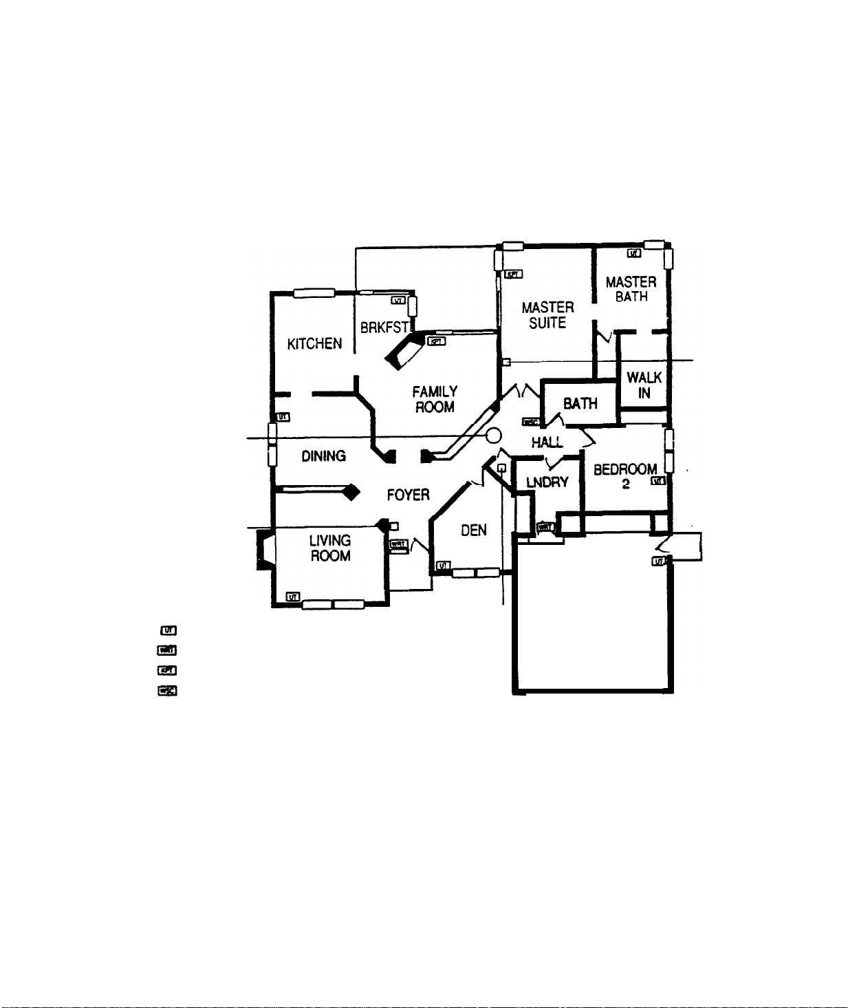
Possible Central Controller and Transmitter Locations
Supervised
Smoke
Transformer
PIRT
with
Curtain
Lens
Universal Transmitter
@!I
Ial
Wireless
@!I
Keypad Transmitter
ISI
Wireless
I---
Remote Transmitter
Siren Controller
LIVING
ROOM
4
I
m
P
Central
GARAGE
Controller
AT&T Proprietary Information
2-12
Page 14

Antenna Placement
The antenna for the Central Controller must have a minimum
length of 7 feet and should be run in an area central to
transmitter locations.
Increasing the length of the wire does not proportionally increase
the effectiveness of the reception. Short increases in length run
toward the weakest RF link can increase reception, however, extra
long antennas can actually decrease reception. It is best
less
the antenna length
than I5 feet, if possible.
Poor reception can. occur when the antenna is mounted in an area
where a large metallic object is present. These metallic objects
block the RF waves. Sometimes sources of metal are obvious, such
as washing machines, refrigerators, heaters, etc...Other sources
are better hidden. Metal ducts, other electrical wires, and steel
beams can all cause trouble if the antenna is run on top of or near
them.
‘Note: The antenna wire should not be bundled along with the
phone line or any other wire. Many installers do this to make the
installation look better, however, "no check in’ problems may
appear due to the introduction of electrical noise, such as static,
into the system.
all the
to keep
"I”
CAUTION: Don’t loop antenna wire.
AT&T
Proprietary
2-13
Information
Page 15
Central
Controller
Antenna
Attachment
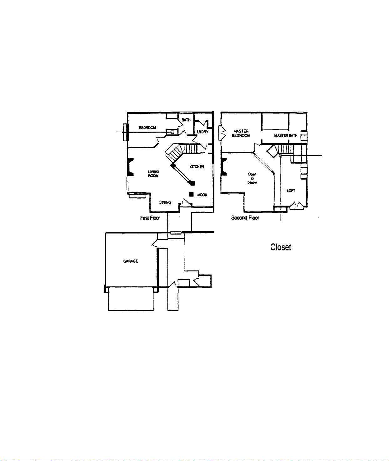
Possible Antenna Run in a Multi-level Home
/
Transformer
Antenna Run
-
Down Stackable
AT&T Proprietary Information
2-14
Page 16
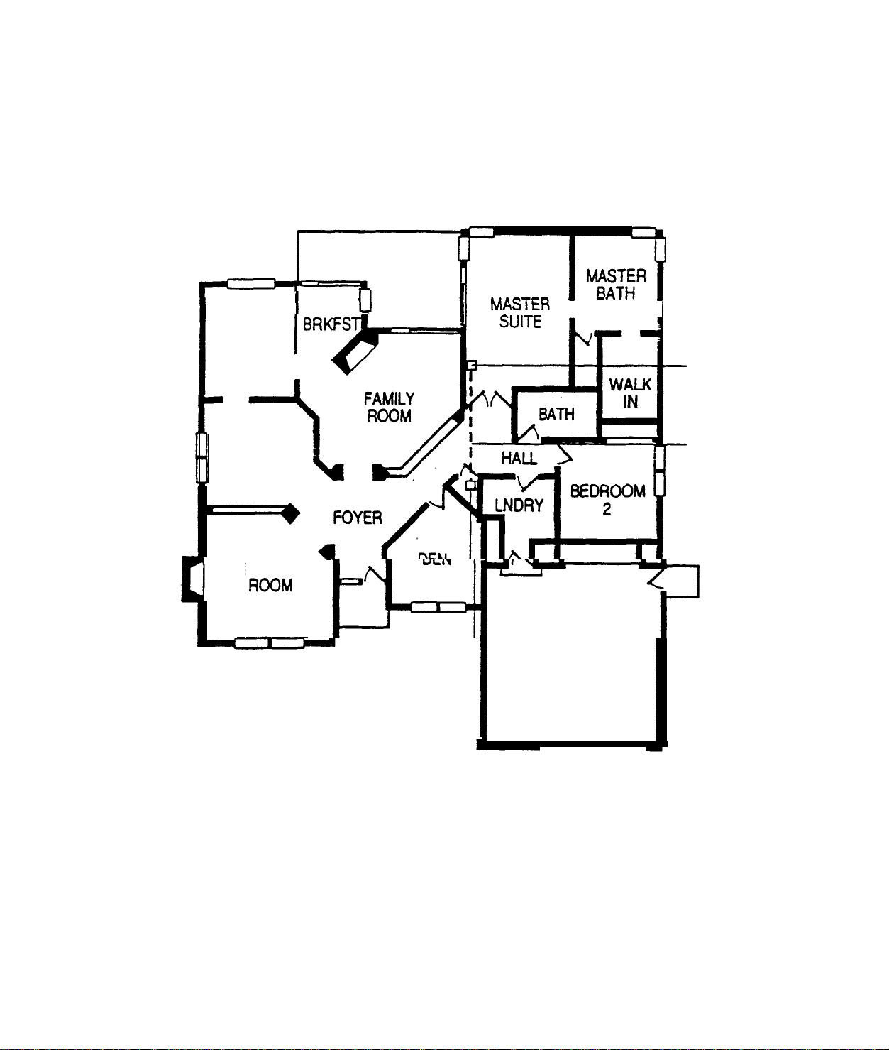
Sample Antenna Run in a Single
Level
Home
KITCHEN
DINING
LIVING
““”
I
u
B4r-l
Central
Controller
GARAGE
I
Transformer
Antenna
Run
I
AT&T Proprietary Information
2-15
Page 17

BUILDING CONSTRUCTION
CONSIDERATIONS
Although the 40.68 MHz band is relatively immune to most small
metal objects in the home or installation site, some house have
building materials that must be taken into consideration. Often, it
is a
combination of several of these factors that cause problems.
Some problems to watch out for.
.
Concrete and brick with metal reinforcement
Large amounts of concrete and brick can be
troublesome, particularly in
the signal must pass through several outer walls.
Wire lath in plaster walls
.
.
Insulation
Foil-backed insulation placed in inner walls may reflect
RF transmissions
.
.
Foil-backed wallpaper or large mirrors
Stuccowalls
Stucco is applied to a wire mesh base that may cause
problems,
How to avoid these problems:
.
Don’t mount the Central Controller on a wall that
especially
contains metal, lath, or stucco mesh.
in
"L" -
shaped homes where
"L" -
shaped homes.
Remember, it’s critical that you identify sources of possible RF
interference and potential blocks to RF waves.
AT&T
Proprietary
Information
2-16
Page 18
STEP 6
Install the
Central
Controller
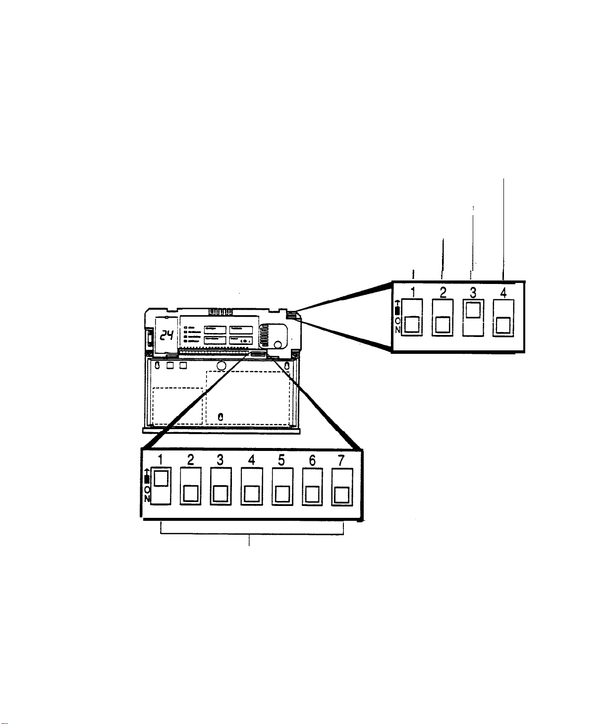
Before you begin learning about how you will install the Central
Controller,
you the DIP SWITCHES which
programmed). You can also see by the pointers where there
switches are located.
take a look at the diagram below. Here we’ve shown
will
need to be set (or
Hard wired loop option
Hard wired loop option
Internal sounder setting
Interior zone sensors setting
u
I
I
I
I
1.
I
I
I
N
House code
AT&T Proprietary Information
2-17
Page 19
A
.
Program
the
Central
Controller
1. Set the House Code DIP switches.
The HOUSE CODE is used to distinguish components in one
system from those in a neighboring system. It must be the same
for every component in a given system. Seven DIP switches are
used to program the house code.
Caution: it would be easy to program the House Code upside
down. Be sure the transmitter is correctly oriented before starting.
It’s a good idea to determine the house code before going on an
installation so that you can prevent duplicating neighboring
numbers (especially in condominium complexes and apartment
buildings).
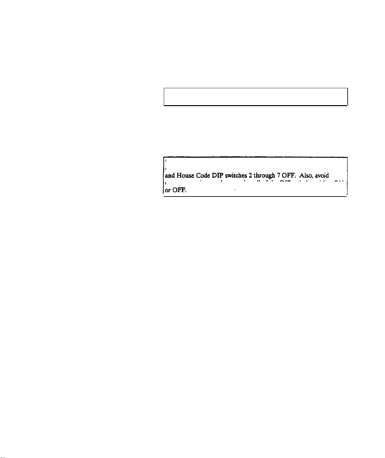
Caution: Do not install the system with the preset default house
code. The default code is set with House Code DIP switch 1 ON
common settings such as putting all of the DIP switches either ON
The following two pages give you a complete listing of all possible
house codes. Just assign any number you choose to the current
installation,
AFTER YOU VERIFY THAT NUMBER IS NOT
IN USE WITHIN A HALF MILE RADIUS.
AT&T Proprietary information
2-18
Page 20

House Code DIP SWITCH Combinations
House House Code Dip
Code 1
000
001
002
003
004 OFF OFF OFF OFF ON OFF OFF
005
006
007
008
009
010
011 OFF OFF OFF ON OFF ON
012
OFF OFF OFF ON ON OFF ON
013
014
OFF OFF OFF ON ON ON OFF
2
OFF OFF OFF OFF OFF OFF OFF
OFF OFF OFF OFF OFF OFF ON
OFF OFF OFF OFF OFF ON OFF
OFF OFF OFF OFF OFF ON ON
OFF OFF OFF OFF ON OFF ON
OFF OFF OFF OFF ON ON OFF
OFF OFF OFF OFF ON ON ON
OFF OFF OFF ON OFF OFF OFF
OFF OFF OFF ON OFF OFF ON
OFF OFF OFF ON OFF ON OFF
OFF OFF OFF ON ON OFF OFF
3
Switch
Settings
4
5
6
ON
7
015 OFF OFF OFF ON ON ON ON
016
017 OFF OFF ON OFF OFF OFF ON
018
019 OFF OFF ON OFF OFF ON ON
OFF OFF ON OFF OFF OFF OFF
OFF OFF ON OFF OFF ON OFF
House House Code Dip Switch Settings
Code
032
033
034
035
036
037
038
039
040
041
042
043
044
045
046
047
048
O49
050
051
1
2 3
OFF ON
OFF ON
OFF ON
OFF ON
OFF ON
OFF ON
OFF ON
OFF ON
OFF ON
OFF ON
OFF ON
OFF ON
OFF OFF OFF OFF OFF
OFF OFF OFF OFF ON
OFF OFF OFF ON OFF
OFF OFF OFF ON ON
OFF OFF ON OFF OFF
OFF OFF ON OFF ON
OFF OFF ON ON OFF
OFF OFF ON ON ON
OFF ON OFF OFF OFF
OFF ON OFF OFF ON
OFF ON OFF ON OFF
OFF ON OFF ON ON
4
5
OFF ON OFF ON. ON OFF OFF
OFF ON
OFF ON
OFF ON
OFF ON
OFF ON ON
OFF ON ON ON OFF
OFF ON ON ON ON
ON OFF OFF OFF OFF
OFF ON ON OFF OFF OFF ON
OFF ON
OFF ON
ON OFF OFF ON OFF
ON OFF OFF ON ON
6
7
OFF ON
020
021
022
023 OFF OFF ON OFF ON ON ON
024
025
026
027
028
029
030 OFF OFF ON ON ON ON OFF
031
OFF OFF ON OFF ON OFF OFF
OFF OFF ON OFF ON OFF ON
OFF ON OFF ON ON OFF
OFF
OFF OFF ON ON
OFF OFF ON ON OFF OFF ON
OFF OFF OFF
OFF OFF ON ON OFF ON Off
OFF OFF ON ON OFF ON ON
OFF OFF ON ON ON OFF OFF
OFF OFF ON ON ON OFF ON
OFF OFF ON ON ON ON ON
AT&T
Proprietary
2-19
052
053
054
055
056
057
058
059
060
061
062
063
Information
OFF ON
OFF ON ON OFF ON OFF ON
OFF ON
OFF ON
OFF ON ON ON OFF OFF OFF
OFF ON
OFF ON
OFF ON ON ON OFF ON ON
OFF ON
OFF ON ON ON ON OFF ON
OFF ON ON ON ON ON OFF
OFF ON ON ON ON ON ON
ON OFF ON OFF OFF
ON OFF ON ON OFF
ON OFF ON ON ON
ON ON OFF OFF ON
ON ON OFF ON OFF
ON ON ON OFF OFF
Page 21
House Code DIP SWITCH Combinations
House House Code Dip Switch Settings
Code 1 2 3 4 5 6 7
064
065
066
067
068
069
070
071
072
073
074
075
076
077
078
079
080
081
082
083
ON OFF OFF OFF OFF OFF OFF
ON OFF OFF OFF OFF OFF ON
ON OFF OFF OFF OFF ON OFF
ON OFF OFF OFF OFF ON ON
ON OFF OFF OFF ON OFF OFF
ON OFF OFF OFF ON OFF ON
ON OFF OFF OFF ON ON OFF
ON OFF OFF OFF ON ON ON
ON OFF OFF ON OFF OFF OFF
ON OFF OFF ON OFF OFF ON
ON OFF OFF ON OFF ON OFF
ON OFF OFF ON OFF ON ON
ON OFF OFF ON ON OFF OFF
ON OFF OFF ON ON OFF ON
ON OFF OFF ON ON ON OFF
ON OFF OFF ON ON ON ON
ON OFF ON OFF OFF OFF OFF
ON OFF ON OFF OFF OFF ON
ON OFF ON OFF OFF ON OFF
ON OFF ON OFF OFF ON ON
Code 1 2 3 4 5
096
097
098
099
100
101
102
103
104
105
106
107
108
109
110
111
112
113
114
115
House House
ON ON OFF OFF OFF OFF OFF
ON ON OFF OFF OFF OFF ON
ON ON OFF OFF OFF ON OFF
ON ON OFF OFF OFF ON ON
ON ON OFF OFF ON OFF OFF
ON ON OFF OFF ON OFF ON
ON ON OFF OFF ON ON OFF
ON ON OFF OFF ON ON ON
ON ON OFF ON OFF OFF OFF
ON ON OFF ON OFF OFF ON
Code
Dip Switch Settings
ON ON OFF ON OFF ON OFF
ON ON OFF ON OFF ON ON
ON ON ‘OFF ON ON OFF OFF
ON ON OFF ON ON OFF ON
ON ON OFF ON ON ON OFF
ON ON OFF ON ON ON ON
ON ON ON OFF OFF OFF OFF
ON ON ON OFF OFF OFF ON
ON ON ON OFF OFF ON OFF
ON ON ON OFF OFF ON ON
6 7
084
085
086
087
088
089
090
091
092
393
094
395
ON OFF ON OFF ON OFF OFF
ON OFF ON OFF ON OFF ON 117
ON OFF ON OFF ON ON OFF
ON OFF ON OFF ON ON ON 119
ON OFF ON ON OFF OFF OFF
ON OFF ON ON OFF OFF ON
ON OFF ON ON OFF ON OFF
ON OFF ON ON OFF ON ON
ON OFF ON ON ON OFF OFF
ON OFF ON ON ON OFF ON
ON OFF ON ON ON ON OFF
ON OFF ON ON ON ON ON
116
118
120
121
122 ON ON ON ON Off ON OFF
123
124
125 ON ON ON ON ON OFF ON
126
127
ON ON ON OFF ON OFF OFF
ON ON ON OFF ON OFF ON
ON ON ON Off ON ON OFF
ON ON ON OFF ON ON ON
ON ON ON ON OFF Off OFF
ON ON ON ON OFF Off ON
ON ON ON ON OFF ON ON
ON ON ON ON ON Off OFF
ON ON ON ON ON ON OFF
ON ON ON ON ON ON ON
AT&T Proprietary Information
2-20
Page 22

Set the Options DIP switches by following these
2.
Switch 1 sets all system transmitters in the interior zone to
either of the following
guidelines:
ON =
interior delayed
OFF = interior instant
Switch 2 determines whether the Central Controller’s
internal
sounder is on or off during an intrusion alarm.
ON = silent
OFF =
on
Switch 3 sets the Central Controller's
hardwired sensor
loop to either of the following:
ON =
OFF =
open loop
closed loop
Switch 4 sets the Central Controller’s hardwired loop zone
to either of the following:
ON =interior
OFF = perimeter instant
B. Mount the Central Controller
Use #8 screws. PLEASE USE A SMALL LEVEL TO MAKE
SURE THE HOUSING IS LEVEL BEFORE YOU TIGHTEN
THE SCREWS.
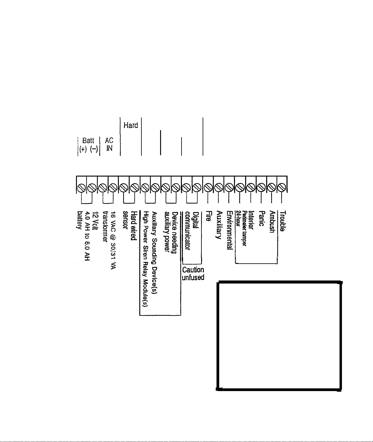
Good!Before you begin wiring in all the components, please take a look at the diagram of the Central
Controller Terminal Strip on the next page. Each terminal screw is labeled for your information.
AT&T Proprietary Information
2-21
Page 23
Central Controller Terminal Strip
USE UL LISTED COMPONENTS
12.0 to 14.5 VDC MAX
d
600 600
mA
TOTAL
I
wired Horns Power Out
sensor
loop(+)
1 2 3 4 5 6 7 10 11 12 13 14 151617 18 19 20 27 22
Sirens
(-)
(12VDC) (12VDC)
(+)
(-)) (-) (+)
Digital Communicator
Output
CHANNELS
1
2
3 4 5 6 7
8
There are two versions of the
Model 8720 Central Controller. In
one version (not shown) an
Fused
3/4
A
AT&T Proprietary Information
2-22
added terminal
9(-)
additional siren output and thus
respectively. In the other version
(shown here) terminals 8 and 9
1
Intrusion
IMPORTANT NOTE:
8(+)
and terminal
are used to provide an
duplicate the function of
terminals (7+) and 10(-),
have been eliminated.
Page 24
STEP 7
Install
the Digital Communicator
NOTE: The 8700 Digital Communicator is probably installed.
If it’s not, please follow
these steps.
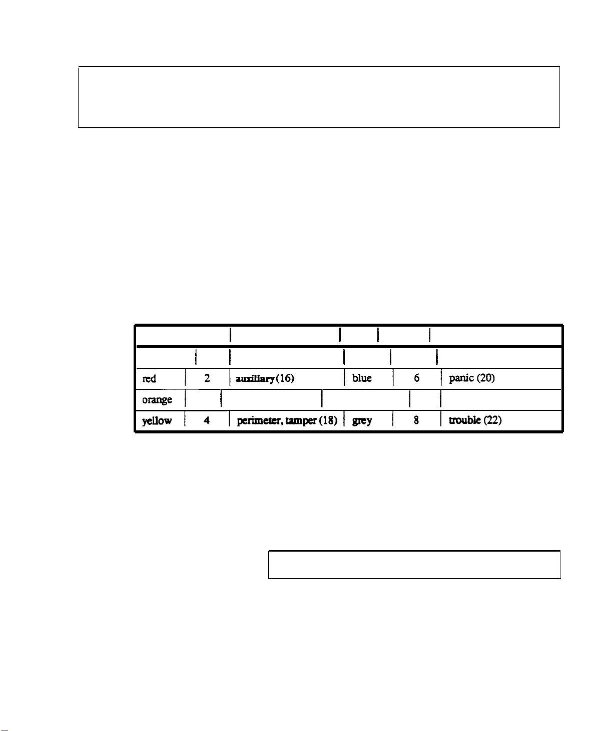
Color Channel
brown
1
1
3.
4.
1
Controller
1
fire (15)
1.
2.
Plug the 8 wire ZONE
INPUT
Communicator.
Plug the polarized 2 wire power connector into the Digital
Communicator.
Peel off the protective backing from the two adhesive
strips on the back of the Digital Communicator, Mount
the Digital Communicator in the lower right hand side of
the AT&T 8720 Central Controller.
Wire the Channel connector to the AT&T 8720 Central
Controller.
Terminal 1
Color 1 Channel 1 Controller Terminal
1
green
1
5 1 interior(19)
connector into the Digital
orange
3 1
environmental(17)
5.
CAUTlON:
greater than 16 volts can damage the Digital communicator.
AT&T Proprietary Information
1
violet
1
7
1
ambush(21)
Connect the black wire to terminal (U) and the red to
8720
terminal (14) of the AT&T
Central Controller. The
Digital Communicator is circuit protected against polarity
reversal. The 1 amp fast blow fuse protects against
excessive power consumption.
Do
not connect to any other power source. Voltages
2-23
Page 25

CAUTION: If it is necessary to change the time of the first test
)
T
(red) =
incoming
Tip
R (green)=Incoming Ring
6.
The red LED (DS1) on the Digital communicator
be blinking to show normal operation. The LED will not
light
if there is no DC power. A steady LED means the
Watchdog circuit has detected a processor or memory
problem.
Reset the watchdog with the AT&T Model
8710 Digital communicator Programmer or AT&T Model
8711 Remote Programming Package.
7.
Connect terminal to earth ground. Use a minimum 14GA
wire. The wire run should be as short and straight as
possible. Sharp angles in the wiring run reduce the
effectiveness of the ground.A good earth
for phone line lightning protection.
T1
(grey)
= House
R1 (brown)
=
phone
House
Tip
phone
AT&T’s
(Seized
Ring
model 8711 Remote
8.
Connect the phone line cord to terminal block
9.
essential
Program the Digital Communicator using the
Model 8710 programmer or
Programming Package. Complete programming
information is available in the Digital Communicator
reference
materials located at the back of this binder.
ground is
TB1.
Tip)
(Seized
should
Ring)
AT&T
CAUTION: The Central Controller provides a total of 600 MA to
be shared by the digital communicator, auxiliary sounding
devices, and other auxiliary devices. Do
not exceed this
10. Connect the Digital Communicator.
-
Attach the power wires
to terminals l3 and 14 of the
Central Controller.
-
Attach
communicator
channel
wires to
Central
Controller screw terminals 15 through 22.
AT&T Proprietary
information
2-24
total.
Page 26

STEP 8
Run the Central
Controller Antenna
Choose the antenna run
Apply the information presented in the Installation Information
section to the house in which you are installing the system.
It is critical
Identify
Attach
the transfomer location
the antenna to the Central
Controller
Connect at least 7
terminals 3 and 4.
that you
-
Sources of possible RF
-
Potential blocks to RF waves
identify:
interference
Find a common unstitched household outlet that is close to the
antenna run.
feet of X18
AWG wire Central Controller screw
AT&T Proprietary Information
2-25
Page 27

STEP 9
Power Up the
Central
Controller
Attach the
antenna
to the
Plug in the
Verify
power
Central Controllet
transfomer
Transformer
CAUTION: BEFORE
YOU POWER UP, PROGRAM AT LEAST
ONE WIRELESS REMOTE/TRANSMITTER SO YOU CAN
IMMEDIATELY ENTER THE
INSTALLER TEST MODE.
Use only a 16 VAC transformer, Comcode number 845402734.
Plug the transformer into the
waII
secure to the
using the 6-32 screw provided.
CAUTION: The transformer is fused, so be careful not to short
120
VAC, 60 Hz, wall outlet and
’
the leads.
NOTE: Do not plug the transformer into an outlet that is
controlled by a
waII
switch.
Verify that the Central Controller is receiving AC power by
checking to see that:
The AC Power LED is
.
on.
Two dashes
.
(-
-) appear in the digital display.
AT&T Proprietary Information
2-26
Page 28

STEP
10
Enter the Installer Test Mode
a. Enter the transmitter security code and then press the OFF key
to put the system in the OFF state.
b. Press the Test/Demo key on the Central Controller. The
digital display will show an ‘88’.
Note: Quickly press the Test/Demo key. If it’s held down for
more than 3 seconds, the Demonstration Mode will be entered
instead of the installer Test Mode and a “-0.” will appear in the
digital display.
c. Touch alI four keys on the Central Controller at the same time
(Messages, Clear Display, Cancel, and Test/Demo). The digital
display will show a ‘CC’. See illustration below.
d. Listen for the Installer Test Mode
There will be one beep every forty seconds.
indiation
beeps to start.
AT&T Proprietary information
2-27
Page 29

STEP 11
Choose
Transmitter
Locations
Mounting
Wireless Remote/Transmitter and
Keypad Transmitter
Universal
Passive Infrared Transmitter (PIRT)
Transmitterr
The normal mounting height for the Wireless Remote/Transmitter
4-l/2
to
5-l/2
and the Keypad Transmitter is between
feet for
convenient access to the keypads. Avoid mounting on metal door
or window
frames.
Universal Transmitters should be mounted at a height of at least
four feet. A higher
installation
produces the best radiation pattern.
Avoid mounting on metal door or window frames.
Placement of the PIRT determines the detection pattern.
The PIRT may be mounted either on a flat wall or in
a
comer.
A mounting height of
.
7-l/2
feet provides the best
combination of sensitivity and coverage.Mounting above
this height increases coverage, but decreases sensitivity,
while mounting below this height increases sensitivity, but
decreases coverage.
Allow at least two inches between the unit and the ceiling
to permit servicing.
.
If using the Pet
(8561) mount the PIRT 4 to 4
AIIey
Mask (8560) or Pet
l/2
AIIey Lens
feet above the floor.
Avoid mounting PIRT where direct
.
sunlight
may strike it.
The customer should be able to identify sun patterns. The
unit should not beng of placed where strong sunlight will strike
directly
on the
face of the
detector.
Be wary of
glasstopped tables or mirrors that are capable of reflecting
direct sunIight toward the PIRT..Indirect sunlight shining
through windows
wiII
not trigger an
alarm.
AT&T Proprietary Information
2-28
Page 30

NOTE: Avoid hot and cold air currents. Mount the unit at
least three feet from strong forced-air heaters, air
conditioners, or sources of drafts such as doors.The hot
or cold air currents may cause false alarms, since the
detector will sense a rapid change in temperature.
.
Choose a location at right angles to an intruder’s path. The
PIRT has optimal detection when placed so that an
intruder’s
pattern.
Avoid large objects that may obstruct the lens.
.
Choose the proper lens:
,
path would be directly across the detection
PIRT
The wide-angle lens provides wide-area
a large space such as a room.
COMMON PLACEMENT OF THE PIRT 8560 OR 8561
Window
ip
Intrusion
-71
coverage to protect
_ Protection
zones
t
I
Room door intrusion
AT&T Proprietary Information
2-29
Page 31

PIRT WIDE-ANGLE
LENS COVERAGE
ZONE
Main
Intermediate
Lower
Lookdown
AT&T Proprietary Information
2-30
Page 32

Curtain Lens
ZONE
Main
Intermediate
The curtain lens provides a long and
hallways and other such narrow areas.
PIRT 8560 OR 8561 CURTAIN LENS COVERAGE
TOP VIEW CURTAIN LENS
FIELD OF VIEW
r
1
VERTICAL RANGE
narrow field of coverage for
Typical
Detection
Zone
Segments
7
10
J
Lower
Look down
SIDE V
EG
I
141
IEW CURTAIN LENS
L
3’6
34
VERTICAL RANGE
AT&T Proprietary Information
2-31
Page 33

Supervised
Smoke Detector
Transmitter (SSD
NFPA
Recommendations for Detector
InstalIation:
The Nation Fire Protection Association’s Standard 74, Section 2-l,
reads as follows:
T)
‘2-1.1.1: Smoke
detectors shall be installed outside of each
separate sleeping area in the immediate vicinity of the bedrooms
and on each additional story of the family living unit, including
basements and excluding crawl spaces and
unfinished
attics. The
provisions of 2-1.1.1 represent the minimum number of detectors
required by this standard. It is
recomm
ended that the householder
consider the use of additional smoke or heat detectors for
increased protection for those areas separated by a door from the
protected
areas
above. The recommended additional areas are: living
dining
room, bedroom(s), kitchen, attic (finished or
by the required smoke detector under 2-1.1.1
room,
unfinished),
furnace room, utility room, basement, integral or attached garage,
and hallways not covered under 2-1.1.1 above. However, the use of
additional detectors remains the option of the householders.’
SSDT Installation Considerations:
.
When ceiling mounted, the SSDT should be located in
hall,
the center of the room or
any
wall.
When the SSDT is mounted on a wall, the top
at least four inches from
of the unit should be four to twelve inches from the
ceiling.
.
Do not install the
SSDT:
where normal ambient temperatures are above
degrees F. or below 40 degrees F.
l20
in
front of air conditioners, heating vents, or other
will
locations where normal air circulation
keep
smoke from entering the detector.
AT&T Proprietary Information
2-32
Page 34

Other Installation Considerations:
To minimize the risk of fire causing injury, loss of life or property,
detectors
basement to the
sleeping
. Between sleeping areas and potential sources of fire such as
should be located on every level of the home from the
attic, (furnished or unfurnished), and in every
area. More specifically, detectors should be located:
the kitchen, garage, basement or utility room. In homes
with only one sleeping area on one floor, a detector should
be put in the hallway outside the bedrooms.
In single floor
homes with two separate sleeping areas, two detectors are
required, one outside each bedroom area.
In multilevel homes, detectors should be located in
bedroom areas and at every finished level of the home.
Basement level detectors should be located in the bottom of
the basement stairwells. Second floor detectors should be
located at the top of the first-to-second floor stairwell so
long as no door obstruction blocks the path of the smoke.
.
inside every bedroom where a smoker sleeps or an
electrical appliance is operated. This detector shouid be in
addition to the hallway detector described above.
.
Inside all bedrooms where people sleep with the door
closed. Smoke and poisonous gases are significantly
blocked by a closed door. This detector should be in
addition to the hallway detector described above.
.
At each end of a long hallway
serving
the bedrooms.
AT&T Proprietary Information
2-33
Page 35

TYPICAL SUPERVISED SMOKE DETECTOR PLACEMENT IN A MULTILEVEL HOME
Smoke Detectors
For Minimum Protection
Smoke Detectors
For Additional Protection
Heat-Activated Detectors
0
BEDROOM
El
UVlNG
Cl-h. *
RWM
KITCHEN
I
BASEMENT
0
BED
ROOM
A
El
A
9Tl
0
GARAGE
I
‘t
fl
J
AT&T
Proprietary
2-34
Information
Page 36

To avoid false or improper operation, don’t install detectors in the
following areas:
.
-
-
.
-
Typical
single
floor installation
one bedroom area
Bathrooms. Excessive steam from a shower may cause
nuisance alarms.
Directly outside bathrooms.
Too near forced-air ducts used for heating or air
conditioning.Air movement may prevent smoke from
reaching the detector.
Near furnaces
normal combustion products may cause a nuisance
alarm.
The peak of an A-frame type of ceiling. Dead air at the
top may prevent smoke from reaching the detector.
of any type. Air and dust movement and
Typical single floor installation
two bedroom area
Smoke Detectors For Minimum Protection
El
Smoke Detectors For Additional Protection
0
Heat-Activated Detectors
A
AT&T Proprietary Information
2-35
Page 37

STEP 12
Perform RF Link Tests on
Transmitter
Locations
all locations
1.
Use a pencil to press either the Home, Away, or Off key on
the Wireless Remote/Transmitter.
2.
Listen for the proper number of indication beeps from the
Central Controller.
3 Beeps 2 Beeps -
No
Beeps
Check the Central Controller to verify that the proper
3
transmitter I.D. number appears.
4.
Check the
information.
LED
LED CONDITlON
Alarm
ON
OFF
Excellent
Marginal
RF Link.
RF
link. The
transmitter should be relocated.
-
No RF
message was received. A
different location must be
chosen.
status LEDs on the Central Controller for more
MEANING
24-Hour Sensor
Loop Not Secure
24-Hour Sensor
Loop Secure
No Check In
AT&T
ON
OFF
ON
OFF
Battery is Low
Battery is OK
Proprietary Information
2-36
Page 38

STEP 13
Install Sensors that Utilize the Central
Controller hardwired Loop and
Auxiliary Power
1.
2.
Select sensor location.
Remove all power to Central Controller before installing
sensor.
3.
4.
5.
6.
Connect hardwired loop sensor wire to the Central
Controller.
.
.
Reconnect power to Central Controller.
Test the sensor to see if it causes an alarm.
Use screw terminals 5 and 6.
Connect auxiliary power wire to the Central Controller.
Use screw terminals
If not, check voltage on 11 and 12.
11
(+)
and
12 (-).
AT&T Proprietary Information
2-37
Page 39

STEP
14
Run the Phone Line for the Digital
Communicator
1.
Locate the phone line protector block.
2.
Install an RJ3lX block. do not mount the RJ3lX inside of
the Central Controller.
Follow all manufactured installation procedures.
3.
possible, to the phone protector block and attach at both
ends.
4.
Attach connecting cord from the Digital Communicator to
the
RJ3lX
block.
NOTE: Utilize the tamper facility on the RJ3lX to protect the
digital communicator connecting cord from being
disconnected. Wiie the tamper sensor to the Central Controller
unknowingly
hardwired loop screw terminals.
5.
NOTE: If the customer’s phones are not operating properly, refer
to the manufacturer installation instructions for the RJ3lX block
Test the customer's phones foi proper operation.
and the digital communicator.
AT&T Proprietary Information
2-38
Page 40

STEP 15
Install Optional
Auxiliary
Sounding
Devices
Select location for the auxiliary
sounding
device
CAUTION: The Central Controller provides a total of 600 MA to
be shared by the digital Communicator, auxiliary sounding devices,
and one other sensor that may require auxihy power.
Do
not
exceed this total.
Follow
procedures
Connect the auxiliary sounding
device
manufacturer installation
to the Central Controller
Use
screw
terminals
7 (+
)
and 10 (-) for the sounding device.
AT&T
Proprietary
2-39
Information
Page 41

Using The High Power Siren
Relay
Module
I
:A,,
LYll
;;
j
2
3 4
1
12 VOLT
STANDBY
BATTERY
HARD
/
S;;;;R W’RED
5 6 7 10
~-600 mA
‘:’ ‘IRE, VDC)j7
11
._
TOTAL-:
(12VDC)
‘““r”
(12VDC)
11
12 13 14
““‘,
BROWN
~
15
BLUE
1,l
2
16 17
.I
3
RED
C;ANNy
‘s\
all II
JJ
4
BROWN
6.
7
8
j
d
+
SIREN
lwREARElviovEmoNsoFl?iEMoDEL87zocENlmL
NOTE 1
TERMINALS
HIGH-POWER
SIREN
r\
BLUE
HIGH-POWER SIREN
RELAY MODULE
CONFClJ?htlNG TC U.
SEPARATElJL~powERSuppLyWrm
BA37ERYBACKUI’HA~GA-~WW4~
OFBlANDBYBEUBED~POWDL)3JMTERNAL
UsrED ELEcrRONlc
NOTE 2
1023
StRw
REWIBEB
THAT A
y
AT&T Proprietary Information
2-40
Page 42

If the auxiliary sounding device
requires
more powcr than
450
MA,
then install the High Power Siren
Relay Module
Use
the
1.
2.
plastic housing. Do not mount on a metal surface.
following
procedure:
Peel off the tape backing.
Mount anywhere on the inside of the Central controller
STEP 16
Recheck
All Transmitter
Locations
3.
Connect the
red and black wire leads to a UL-listed
external power supply.
4.
5.
Connect
terminal 7(
the
blue wire to the
+).
Central Controller screw
Connect the brown wire to the Central Controller screw
terminal 10 (-).
6.
While the
Siren Relay Module screw terminals (-)
auxiliary sounding device to the High Power
and 2
(+).
NOTE Look at the following diagram showing the High Power
Siren Relay Module properly connected.
See Step 12 for instructions
(p.
2-36).
AT&T Proprietary Information
2-41
Page 43

STEP 17
Program
the Transmitters
An easy way to program the transmitters is to begin by setting the
I.D. code for each one while you have them all together (in the
kitchen of wherever you’re working). That way, since you can look
at them ail at once, you’ll be sure not to give the same I.D. number
to more than one transmitter.
I.D.
Let’s look at the
Code for a moment.
Identification Codes
Each transmitter in the system must have a unique code number.
Fivee DIP switches are used to program the transmitter I.D. The
I.D. number is used by the Central Controller to relay trouble
beeps and alarms to specific transmitters. Code numbers 00
through 31 may be used. Codes
The
Supervised
Smoke Detector Transmitter differs from the other
00
transmitters in that it only has three I.D. DIP
uses code numbers 24 through 31. These codes are shown on Page
62.
Transmitter
ID
Code
00 ON ON ON ON ON
01 OFF ON ON ON ON
02 ON OFF ON ON ON
03 OFF OFF ON ON ON
04 ON ON OFF ON ON
05 OFF ON OFF ON ON
06 ON OFF OFF ON ON
07 OFF OFF OFF ON ON
08 ON ON ON OFF ON
09 OFF ON ON OFF ON
10 ON OFF ON OFF ON
11 OFF OFF ON OFF ON
12 ON ON OFF OFF ON
13 OFF ON OFF OFF ON
14
15 OFF OFF OFF OFF ON
16 ON ON ON ON OFF
17 OFF ON ON ON OFF
18 ON OFF ON ON OFF
19 OFF OFF ON ON OFF
20 ON ON OFF ON OFF
21 OFF ON OFF ON OFF
22 ON OFF OFF ON OFF
23 OFF OFF OFF ON OFF
24 ON ON ON OFF OFF
25 OFF ON ON OFF OFF
26 ON OFF ON OFF OFF
27 OFF OFF ON OFF OFF
27 OFF OFF ON OFF OFF
28 ON ON OFF OFF OFF
29 OFF ON OFF OFF OFF
30 ON OFF OFF OFF OFF
31 OFF OFF OFF OFF OFF
ID
Switch
Settings
1 2 3 4 5
ON OFF OFF OFF ON
through 23 are shown below.
switchess
and only
AT&T Proprietary Information
2-42
Page 44

Use the Zone Locator Card (shown below) to record (IN PENCIL
PLEASE
transmitter as soon as you set
This
Controller just as soon as you finish
available for the
-
neatly and accurately) the
them.
card should be placed in the slot at the back of the Central
customer's
or your company’s use.
I.D. codes of each
filling
it out so it will always be
TRANSMITTER IDENTIFICATION
ID TRANSMITTER
00
cl
01
Cl
02
Ii
-
loal
-
lm
u
05
q
06
q
07
cl
-
losl
losl
10
q
ID
TRANSMllTTER
11
cl
12
q
13
Ll
II
u
15
cl
16
cl
-
1171
-
1181
u
19
0
-
la
21
cl
NUMBERS
ID
TRANSMITTER
22
cl
23
cl
24
iI
25
cl
26
cl
2
a
28
Cl
29
I
30
cl
31
cl
IW CASE OF
DIFFICULTY
CALL
DISPLAY CODES
MEANING
-A
cl
-H
0
@
on
a
FI
cl
•I
CC
q
mr
tlrr
Nasmlm
a&u
UWRn
nanlmlm
ummhM
iisltt
AT&T Proprietary information
2-43
Page 45

Prepare
Remote/Transmitter for
Programming
the
Wireless
1.
Remove the backplate from the Wireless
Remote/Transmitter
Press the release tab on the transmitter backpiate.
2.
Program the transmitter.
Selectable sensor loop zone
House code
setting
1
Transmitter ID
Wireless Remote/Transmitter DIP
AT&T Proprietary Information
2-44
L-
I
I
Selectable sensor loop option
Battery saver
Switches
option
Page 46

. Set House Code/Option DIP Switches:
1 -
7 set
Switches
the house code.
Switch 8 sets the selectable sensor loop zone to either
of the following
=
ON
interior
OFF = perimeter delayed
. Set ID/Options DIP switches:
Switches 1 - 5 set the transmitter identification
number.
Switch 6 sets the selectable sensor loop to either of the
following
ON
OFF
= open loop
= closed loop
Switch 7 sets the battery saver function is used when a
sensor is commonly activated many times on a daily
basis. When the function is set to ON, there is a
minute delay between sensor-activated transmissions.
ON
OFF
_
Switch 8 sets the transmitter for either of the following:
ON
OFF
= Battery saver on
=
Battery
saver off
= high security
= low security
AT&T Proprietary Information
2-45
Page 47

.
Set the security code:
Determine the 3-digit security code.
a.
Consult the customer before programming the security
code to determine:
_
The number of different security codes to be
used.
different number for each transmitter or one
number to be used throughout the system.
For example, the customer may want a
Any particular numbers that
the customer would
like to use. A number with personal meaning
may be chosen so that it will be easy to
remember.
[CAUTION: Don’t use predictable numbers such as
123 or 468.
Also, avoid numbers that involve the customers address or
phone number.
]
1
AT&T Proprietary
2-46
Information
Page 48

b. Plug each security code post into the slot for the number
desired.
Blue Wiie
White Wire
Yellow Wire
NOTE: The proper wire sequence is easy to remember since
=
=
=
First Number
Second Number
Third Number
the
alphabetical order of the colors is the same as the order of the
numbers they represent:
1st = B
3.
Check the voltage on the 9 volt battery using your meter.
2nd = W
3rd =
Y
should register 9 volts. Then connect the 9 volt battery.
Check the current draw.
4.
Log the transmitter location on the Central Controller Zone
Locator Card.
5.
Temporarily place the transmitter in the area that it
mounted. Use double-sided tape to hold it (gently- it might
pull off the wall board!) if necessary.
will
It
be
6. Enter the Installer Test Mode, as described below.
a.
Enter the transmitter security code and then press
the Off key to put the system in the Off state.
NOTE: Next, quickly press the Test/Demo key (Step b.). If it is
held down for more than 3 seconds, the Demonstration Mode will
be entered, instead of the Installer Test Mode and a ‘-0.” will
appear in the digital display.
To clear this condition: Press the Test/Demo key once to exit the
Demo Mode.
AT&T Proprietary Information
2-47
Page 49

b.
The digital display will show an
Press
the Test/Demo key on the Central Controller.
"88".
7.
a.
b.
C.
Within 2 seconds, touch all four keys on the Central
Controller at the same time (Messages, Clear
Display,
Cancel,
and Test/Demo). The digital
display will show a ‘CC”.
d.
Listen for the Installer Test Mode indication beeps to
start.There will be one beep every forty seconds.
Perform the Wireless Remote/Transmitter RF link test.
Use a
pencil
to press either the Home, Away, or Off
key.
Listen for the proper number of indication beeps
from the Central Controller.
3 Beeps -
2 Beeps -
Excellent RF link.
Marginal RF link. The
transmitter should be relocated.
No Beeps -
No RF message was received. A
different location must be
chosen.
Check the Central Controller to verify that the
C.
proper transmitter ID number appears.
d.
Check the status LEDs on the Central Controller for
iuformatiou.
more
AT&T Proprietary
2-48
Information
Page 50

Prepare the Keypad
Transmitter
1.
Remove the backplate from the Keypad Transmitter.
Press the release tab on the backplate.
2.
Program the Keypad Transmitter.
Set the House Code DIP switches.
.
Set the ID/Options DIP switches:
.
Switches
number.
Switch 6 sets the selectable sensor loop to
either of the following:
ON =
OFF
1 -
5 set the transmitter identification
open loop
=
closed loop
House code
1
I
Transmitter ID
1
Battery saver option
Selectable
AT&T
Proprietary Information
2-49
L
High or low
security setting
sensor loop option
Page 51

Switch 7
sets
the battery
either of the following:
saver function to
ON
OFF
= battery saver on
= battery saver off
Switch 8 should be set ON for high security to
allow for the RF link test.
ON
OFF
= high security
=
low security
AT&T Proprietary Information
2-50
Page 52

_
Set the security code:
a.
b.
Determine the 3-digit security code.
Plug each security code post
number desired.
Blue
White Wiie
Yellow
Wire
Wire
into the slot for the
=
=
=
First Number
Second Number
Third Number
Keypad
AT&T
Transmitter
Proprietary Information
Initial Programming
2-51
Page 53

Test battery, under load, then connect the 9-volt battery. It
3.
should register 9 volts on your meter. Check the current
draw.
4.
Log
the transmitter location on the central controller Zone
Locator Card.
Temporarily place the transmitter in the area that it will be
5.
mounted. Use double-sided tape if necessary.
6.
Perform the Keypad Transmitter RF link test.
a.
b.
c.
d.
7.
If the low security option is desired, move DIP switch 8 to
the OFF position.
Use a pencil to move the slide switch.
Listen for the proper number of indication beeps
from the Central Controller.
Check the Central Controller to
verify
that the
proper transmitter ID number appears.
Check the status LEDs on the Central controller for
more information.
AT&T Proprietary Information
2-52
Page 54

Prepare the Universal Transmitter
Remove the backplate from the Universal Transmitter.
1.
Press up on the tab at the bottom
of the housing.
2. Program the Universal Transmitter.
Set the House Code DIP switches.
.
Set the ID/Options DIP switches:
.
Switches
1
-
5 set
the
transmitter identification
number.
Switch 6 sets the sensor loop to either of the
following:
=
ON
OFF
open loop
=
closed loop
AT&T
Proprietary Information
2-53
Page 55

Switch 7 sets the battery saver
of the
following:
function
to either
ON =
OFF = battery saver off
Switch 8 sets the sensor loop zone to either of
the
following:
ON
OFF =perimeter instant
Switch 9 sets the function of the button on the
front of the
"panic”, pressing the button
alarm.
when the button is pressed.
ON = panic
OFF
battery saver on
=
interior
Universal
When set to
= test
"test",
Transmitter. When set to
will
activate an
no alarm is activated.
AUDIBLE PANIC
INTERIOR
OPEN LOOP
AT&T Proprietary
11
2-54
INTRUSION
AUXILIARY
89
ENVIRONMENT
PP
Information
Page 56

Switches 10 and 11 set the type of alarm that
the transmitter
to set the transmitter to Intrusion, Fire,
Auxiliary, or Environmental.
Switch 12 determines whether or not the
transmitter is supervised. A supervised
transmitter checks in to the central Controller.
An unsupervised transmitter doesn’t check in,
thus it can be taken off of the premises with out
causing a
"no
check in”.
will
send. Use the chart below
ON =
OFF
=
Dip
Type Of Alarm
Intrusion ON ON
Switch Settings
10
11
I
Fire
OFF ON
Auxiliary
ON
OFF
supervised
unsupervised
I
Environmental
Universal Transmitter
AT&T Proprietary Information
2-55
OFF OFF
Alarm
Settings
Page 57

3.
Test the voltage of your
9-volt
battery. Connect the
battery. Check the current draw.
4. Log
Zone Locator Card.
5.
6.
Temporarily place the transmitter in the area that it will
be mounted. Use double-sided tape, if necessary.
Perform the Universal Transmitter RF link test.
a.
b.
C.
d.
the transmitter location on the
Use a pencil to press the Alarm/Test button.
Central
Controller
Listen for the proper number of indication beeps
from the Central Controller.
Check the Central Controller to verify that the
proper
transmitter
ID number appears.
Check the status LEDs on the Central Controller
for more information.
AT&T
Proprietary Information
2-56
Page 58

Prepare the
Transmitter (PIR
Passive Infrared
T)
1.
Verify the proper location for the PIRT.
Apply
section on PIRT placement considerations.
the information presented in the Pre-Installation
2.
Remove PIRT housing.
Press the release tab on the top to the housing.
3.
Carefully remove the circuit board from the housing.
Press the circuit board release tabs.
4.
Choose the proper lens for the PIRT and change the lens
if necessary.
Remember that the PIRT is shipped with the wide-angle
lens pre-installed
Follow
these steps to change the lens.
a.
Press outward on the vertical supports which
hold the lens brackets.
b..
c.
Remove the lens brackets and the old lens.
Place the new lens under the top and bottom
tabs.
d.
If you’re using a 8560 and want to install the Pet
Alley Mask:
_
Place
down lens.
_
Place the top mask over the regular lens
and under the top and bottom tabs. (If
you’re using a
Lens)
e.
AT&T Proprietary Information
2-57
Replace lens brackets
the
look-down mask over the look
8561,
install the Pet Alley
carefully.
Page 59

5. Program the PIRT.
NOTE: The PIRT should be held upside-down for the DIP
switches to be oriented properly for programming.
.
Set House Code DIP switches.
Set ID/Options DIP switches:
.
_
Switches 1 - 5 set the
transmitter identification
number.
Switch 6 should be placed in the OFF position.
Switch 7 should be placed OFF in order to set the
transmitter for walk-test operation.
AT&T Proprietary Information
2-58
Page 60

Switch 8
the following:
sets the transmitter sensor zone to either of
ON =
OFF = perimeter instant
Stitches 9 - 12 should be set to the ON position.
interior
pscH8$E
TRANSMITTER
DIP
SWITCHES
6.
7.
AT&T
l
"Active” Post on PIRT Circuit
Test the battery voitage. It should be 9 volts. Connect the
batteries. Check the current draw.
Log
the
transmitter on the Central Controller Zone
Locator Card.
Proprietary
information
2-59
Board
Page 61

Activate the LED by connecting the walk-test LED plug
8.
to the ‘Active” post on the PIRT circuit board.
9
.
Check to see that DIP switch 7 is set in the OFF
position.
Temporarily mount the PIRT with double-sided tape.
10.
11. Perform the PIRT RF link test.
a.
Slowly move your hand in front of the PIRT until
the walk-test LED comes on.
b.
Listen for the proper indication beeps from the
Central Controller.
c.
Check the Central Controller to verify that the
proper transmitter ID number appears.
d.
Check the status LEDs on the Central Controller
for more information.
12. Fill unused screw holes to keep out bugs and dust.
AT&T Proprietary Information
2-60
Page 62

Prepare
Detector Transmitter
the
Supervised Smoke
1.
Detector Transmitter.
Use the information presented in the Installation
Information section
location.
Verify the proper location
to help determine the correct
for the Supervised Smoke
2.
Open the detector front housing.
Use a screwdriver to bend the release tab that can be
accessed through a small hole in the backplate.
3.
Program
Set the House code DIP switches.
.
Set the I.D. DIP
.
the detector.
switches.
SMOKE DETECTOR
AT&T
Proprietary information
241
Page 63
Use the chart below to set the
number. Only
Smoke Detectors.
;$t.ns~;
I.D. numbers
1
24
3-DIGIT
through 31 are available for the
smoke detector identification
l,D
Switch
ring
3
4.
5.
24
25
26
27
26
29
30
31
Close the
Check the voltage on the batteries then connect them
Check the current draw.
NOTE: Use only
detector
ON
OFF ON
ON
OFF
ON
OFF ON
ON
OFF
front housing.
Duracell
NM 1604 batteries.
ON
OFF ON
OFF ON
ON
OFF
OFF OFF
ON
ON
OFF
OFF
OFF
.
6.
7.
8.
AT&T Proprietary Information
Log the transmitter location on the Central controller
Zone Locator
Temporarily place the detector in the area it will be
mounted.
Perform the Supervised Smoke Detector Transmitter RF
link test.
2-62
Card.
Page 64

Use a pencil to press the Test button on the detector. Hold
a.
it down until you hear an alarm
tone (approximatety 20
seconds).
b.
Listen
for the proper number of indication beeps from the
Central Controller.
C
Check the Central Controller to verify that the proper
.
transmitter I.D. number appears.
d.
Check the status
LEDs
information..
on the Central Controller for more
AT&T Proprietary Information
2-63
Page 65

STEP
18
Mount the
Mount
Wireless
Transmitters
Remote/Transmitter
1.
Mount the sensor to be used with the transmitter. (Follow
the sensor manufacturer’s instructions.)
2.
Thread sensor wires through the Wireless
Remote/Transmitter
backplate.
Too much wire
housing to seat improperly and
cause false alarms.
3.
Mount the backplate.
Be careful not to over-tighten the backplate screws. False
alarms may result because the housing seats improperly
against the tamper switch.
can
cause the
AT&T
Proprietary Information
2-64
Page 66

4.
Connect sensor wires to the screw terminals on the
backplate for the
desired type of sensor
loop.
If wiring the 24-hour sensor loop, the preinstalled jumper
must be removed. Otherwise, make sure the 24-hour
jumper is firmly installed.
5.
Connect the snap caps or spade lug wires to the screw
terminals.
The snap caps and wires are color coded
for each
terminal.
CAUTION: The wires should not end up on top of (or under) the
battery or on the tamper switch - could cause false alarms.
6.
Attach the front housing.
]
1
RESPONSE-500 mSEC
-24-Hour
LOOP
‘SELECTABLE
AT&T
Proprietary Information
LOOP
USE JUMPERS
TO CLOSE LOOPS
FOR HANDHELD USE
2-65
Page 67

7.
Perform the sensor activation RF test.
This test is used to verify the correct functioning of the
sensor and the RF link of the mounted transmitter.
Mount
Keypad
Transmitter
a.
b.
c.
d.
1.
2.
3.
Mount the sensor to be used
Follow the sensor manufacturer’s instructions.
Thread sensor wires
backplate.
Mount the backplate.
Activate
Listen for the proper number of beeps from the
Central Controller.
Check the Central Controller to verify that the
proper transmitter I.D. number appears.
Check the status
for more information.
the
sensor.
LEDs
through
on the Central Controller
with
the transmitter.
the Keypad Transmitter
Be careful not to over-tighten the backplate screws.
4.
5.
6.
AT&T Proprietary
Connect sensor wires to the screw terminals on the
backplate for the desired type of sensor loop.
Connect the snap caps or spade lug wires to the screw
terminals.
Attach the front
2-66
housing.
Information
Page 68

7.
Perform the sensor activation RF test.
Mount Universal Transmitter
1.
2.
a.
b.
C.
Activate the sensor.
Listen for the proper number of beeps from the
Central
Check the Central Controller to
ControIIer.
verify
that the
proper transmitter I.D. number appears.
d.
Check the status LEDs on the Central Controller
for more information.
Mount the sensor to be used with the transmitter.
Follow the sensor manufacturer’s instructions.
Thread sensor wires through the Universal Transmitter
backplate or choose portable backplate for hand-held use.
AT&T Proprietary
2-67
Information
Page 69

3.
Mount the backplate.
Be careful not to over-tighten the backplate
4.
5.
6.
7.
Connect sensor wires, if used, to the screw terminals on
the backplate.
Connect the snap caps or spade lug wires to the screw
terminals.
Attach the front housing.
a.
b.
c
d.
Perform the sensor activation RF test.
Activate the sensor.
Listen for the proper number of beeps from the
Central Controller.
Check the Central
proper transmitter I.D. number appears.
Check the status
for more information.
Controller
LEDs
to verify that the
on the Central Controller
screws.
AT&T Proprietary Information
2-68
Page 70

Universal Transmitter Applications
UNIVERSAL TRANSMITTER
SENSOR LOOP:
PANIC
APPLlCATiONS
SEL
ECTABLE I OOP
PROGRAMMING
UNIVERSAL TRANSMITTER
SENSOR LOOP:
FIRE APPLICATIONS
SF’
FCfABl F
PWXXAMVi%JG
I
WENWCM
LOOP
UNIVERSAL TRANSMITTER
SENSOR LOOP:
AUXILIARY APPLlCATlONS
SEL
ECTABLE LOOP
PROGRAMMING
PORTABLE BACKPLATE
1. OPEN CIRCUIT
2. PANIC BUTTON ENABLED
3. SUPERVISED UNSUPERVISED
.
OPERATION OPERATION
UNIVERSAL TRANSMITTER
SENSOR LOOP:
ENVIRONMENTAL
APPLICATONS
MAeLF
PRCxXAMMING
LOOP
AT&T Proprietary Information
2-49
Page 71

Mount Passive Infrared Transmitter
(PIRT)
Mount the PIRT backpiate with #6 screws. For a corner
1.
mount, use the mounting guides on the angled sides of the
backplate.
2.
Attach the front housing to the backplate. Allow the
several minutes to stabilize.
3.
Walk test the PIRT to verify its coverage.
a.
b.
c.
d.
e.
f.
unit
Reduce the sensitivity of the PIRT by using the
sensitivity adjustment knob on the circuit board.
(8560 only)
Turn the knob counterclockwise. (8560 only)
Walk in several different paths across the detection
area. (For 8561 there is
Listen
for the proper number of indication beeps.
no
sensitivity adjustment)
Watch to see that the reh walk-test LED light
comes on when you move.
Check to see that the walk-test LED doesn’t light
when you stand out of range of the detection zone.
Adjust the sensitivity up as necessary. (8560 only)
4.
5.
Park the LED.
Disconnect the LED plug
a.
on the
b.
Connect the LED
PlRT circuit board.
Deactivate the walk test by moving DIP switch 7 to the ON
position.
NOTE:
"on" will
Failure to disable the walk-test LED and set switch X7 to
shorten battery life.
AT&T Proprietary Information
2-70
from the "Active” post
plug
to the
"Park" post.
Page 72

Mount Supervised Smoke
Transmitter
Detector
1.
Remove
Use the release tab
mounting.
the back bracket from the detector.
marked
"Press"
to remove back for
STEP 19
Exit the Installer Test Mode
2.
Mount the detector bracket.
3. Install the detector onto the bracket.
4.
Perform second RF
link
test.
a. Use a pencil to press the Test button on the front of
the detector.
b.
C
.
Listen for the proper number of
Central
Controller.
Check the Central ControlIer to verify that the
beeps
proper transmitter I.D. number appears.
d.
Check the status LEDs on the Central Controller for
more information.
1.
Use the MESSAGES key on the Central Controller to scroll
through the I.D. numbers.
- If any are missing, go back and RE-test that transmitter
now.
from the
-
To remove unwanted numbers, press the CLEAR
DISPLAY key now.
2.
3.
Press the Test/Demo key on the Central Controller.
Verify that the Installer Test Mode has been exited
-
Check the Central Controller digital display to
confirm that the ‘CC” has changed to ‘-0” to indicate
that the system is in the Off state.
-
Listen to verify that the Installer Test Mode
indication beeps have stopped.
AT&T Proprietary Information
2-71
Page 73

STEP 20
Program the wireless Siren/Controller
Set the House Code/Option DIP SWITCHES:
- Switches 1 - 7 set the House Code.
-
Switch 8 determines whether the Witless Siren/Controller’s
internal sounder is on or off during an intrusion alarm.
Choose
Antenna
Run the Antenna/Power
the
Wireless
Siren
Run
Line
WIreless Siren/Controller
Transfonner
-
Switch 9 should ALWAYS be ON.
/Controller
-
Sources of possible RF interference
-
Potential blocks to RF waves
The
to
from
the
the
Connect the antenna/power wire to the TOP two screw terminals
labeled ‘12 VAC POWER IN”.
ON =
OFF =
Silent
Sound
Apply the information presented in the Installation Information
section to each individual installation. It’s critical that you identify:
power
cord/antenna wire
should
be #18
AWG
wire.
House
AT&T
code
Internal sounder setting
system setting (always up)
Proprietary
Information
2-72
Page 74

Run optional
auxiliary
sounding device
wires to the Wireless Siren/Controller
CAUTION: The Wireless Siren/Controller provides a total of
MA
If an
wires to the terminals labeled ‘ONE OR
SIRENS”. Use the strain relief posts.
Install the auxiliary sounding device(s)
according to the manufacturer’s
instnrctions
Thread all
wires through the plastic strain
relief posts before connecting to screw
terminals
Attach the power cord/antenna wire to
Use only a Comcode Number 8456837 12 VAC transformer.
the transformer
Plug in the
transformer
Use a 120 VAC, 60 Hz, wall outlet. Secure the transformer with
the screw provided (#6-32).
for auxiliary sounding devices. Do NOT exceed this total.
auxiliary
sounding device(s) is being installed, connect the
TWO
EXTERNAL
450
Verify that the AC Power Light is ON
12 VAC
power
in
AT&T
Proprietary
2-73
Information
Page 75

Connect the Battery
Enter the Wireless Siren /Controller
Test Mode
Test the RF Link
Use the
9-volt battery that’s included. BE SURE TO TEST IT
FIRST!
1. Press the internal ‘CANCEL’ button. Hold it for 6 SECONDS.
The
Wireless Siren/Controller will beep once when the button is
pressed and again when it goes into the TEST MODE.
2. Listen for the Wireless Siren/Controller Test Mode indication
40
beeps to begin. There will be one beep every
1. Press the Test/Demo key on the Central Controller.
2. Listen for the verification beeps from the Wireless
Siren/Controller.
seconds.
1 Beep =
2 Beeps =
No Beeps =
NOTE: 8 beeps indicate the Central Controller has failed to check
in. This can only happen after the initial installation of the system.
Exit Wireless Siren/Controller Test Mode Press the internal
Siren/Controller.
"CANCEL"
Excellent RF link
Excellent RF
Low Battery
No RF message
Relocate Wireless Siren/Conrollerr
until 1 Beep is heard
button on the Wireless
link
AT&T Proprietary Information
2-74
Page 76

STEP 21
Perform the System Test
System Test Intrusion Transmitters
1. Arm the system to the Away ststate using a wireless
Remote/Transmitter.
System Test
2.
3.
Trip each intrusion transmitter.
Listen for the appropriate alarm sounding patterns from the
the Central Controller.
4.
Use the Wireless Remote/Transmitter to disarm the
system.
5.
Press the Messages key on the Central Controller to verify
that the proper signals were received.
6.
Call the Central Station to verify
and account code were received.
Hardwired 1. Arm the System
2. Trip each hardwired loop sensor.
that the proper channel
3.
Listen for the appropriate alarm from the Central
Controller.
4.
5.
Disarm the system.
Press the Messages key on the Central controller to verify
that the proper signals were received.
6.
Call the Central Station to verify that the
and account code were received.
AT&T
Proprietary Information
2-75
proper channel
Page 77

System Test 24-Hour Zone
Transmitters
1.
Trip each 24-Hour zone transmitter (tire, panic, auxiliary,
environmental).
RF
Scanner
2.
Listen for the appropriate alarm sounding patterns from
the Central Controller.
3.
4.
Reset the alarm system (disarm or cancel).
Press
the Messages key on the Central Controller to verify
that the proper signals were received.
5.
Call the Central Station to verify that the proper
and account code were received.
Refer to TECH
TIPS,
about testing with
channel
Volume I, Number 4, page 2 for information
an RF
Scanner.
AT&T Proprietary Information
2-76
 Loading...