

Page 1

AT&T System 75
and System 75 XE
Wiring
Copyright © 1987 AT&T — All Rights Reserved
Printed in U.S.A.
555-200-111
Issue 1, April 1987
Page 2

TO ORDER COPIES OF THIS MANUAL
Call:
Write:
Call:
AT&T Customer Information Center on 800-432-6600
In Canada Call 800-255-1242
AT&T Customer Information Center
2855 North Franklin Road
P. O. BOX 19901
Indianapolis, Indiana 46219
TO COMMENT ON THIS MANUAL
The AT&T Document Development Organization
Hot Line:
800-334-0404
In North Carolina Call 919-727-3167
Every effort was made to ensure that the information in
this document was complete and accurate at the time of
printing. However, information is subject to change. This
document will be reissued periodically to incorporate
changes.
Published by
The AT&T Documentation Management Organization
Page 3

INTRODUCTION
CONTENTS
Page
ORGANIZATION
Use of Guide
Equipment
GENERAL
CROSS-CONNECT HARDWARE SELECTION
WIRING HARDWARE CHANGES
PLANNING
Job Aids
Terminals
Site or Satellite Closets
Cabling Facilities
1-3
1-3
1-4
1-4
1-7
1-7
1-7
1-8
1-8
1-10
1-10
-i-
Page 4

LIST OF FIGURES
Figure 1-1. Documentation Block Diagram
Figure 1-2. System Uniform Wiring Plan
Figure 1-3. Sample Uniform Wiring Installation
Figure 1-4. Sample Floor Plan With Terminal Locations Marked
Figure 1-5. Riser Cable Placement
1-2
1-5
1-6
1-9
1-11
-ii-
Page 5

1. INTRODUCTION
This is one of three documents (Figure 1-1) required for the installation of the System 75 or
the System 75 XE. This guide explains the hardware, job planning, equipment ordering, and
installation information from:
●
The telephone company network interface up to and including the 25-pair cables that
connect directly to the switch and
●
The main equipment room cross-connect field and cabling from this field to the
switch cabinet and to the 8-pin modular wall jacks (information outlets).
Unless a statement is made that a topic is strictly for the System 75 or the System 75 XE,
all information in this document refers to both systems.
The other two documents required for the installation of the System 75 or System 75 XE are
as follows:
AT&T System 75—Installation and Test (555-200-104):
Contains information for installing and testing the System 75 switch and the
attendant console. (For continuity purposes, wiring of the attendant console is
also covered in this guide.)
AT&T System 75 XE—Installation and Test (555-201-104):
Contains information for installing and testing the System 75 XE switch and the
attendant console. (For continuity purposes, wiring of the attendant console is
also covered in this guide.)
AT&T System 75 and System 85—Terminal Installation and Test (999-700214IS):
Contains information for the installing and testing of the voice terminals and
their associated adjuncts.
1-1
Page 6
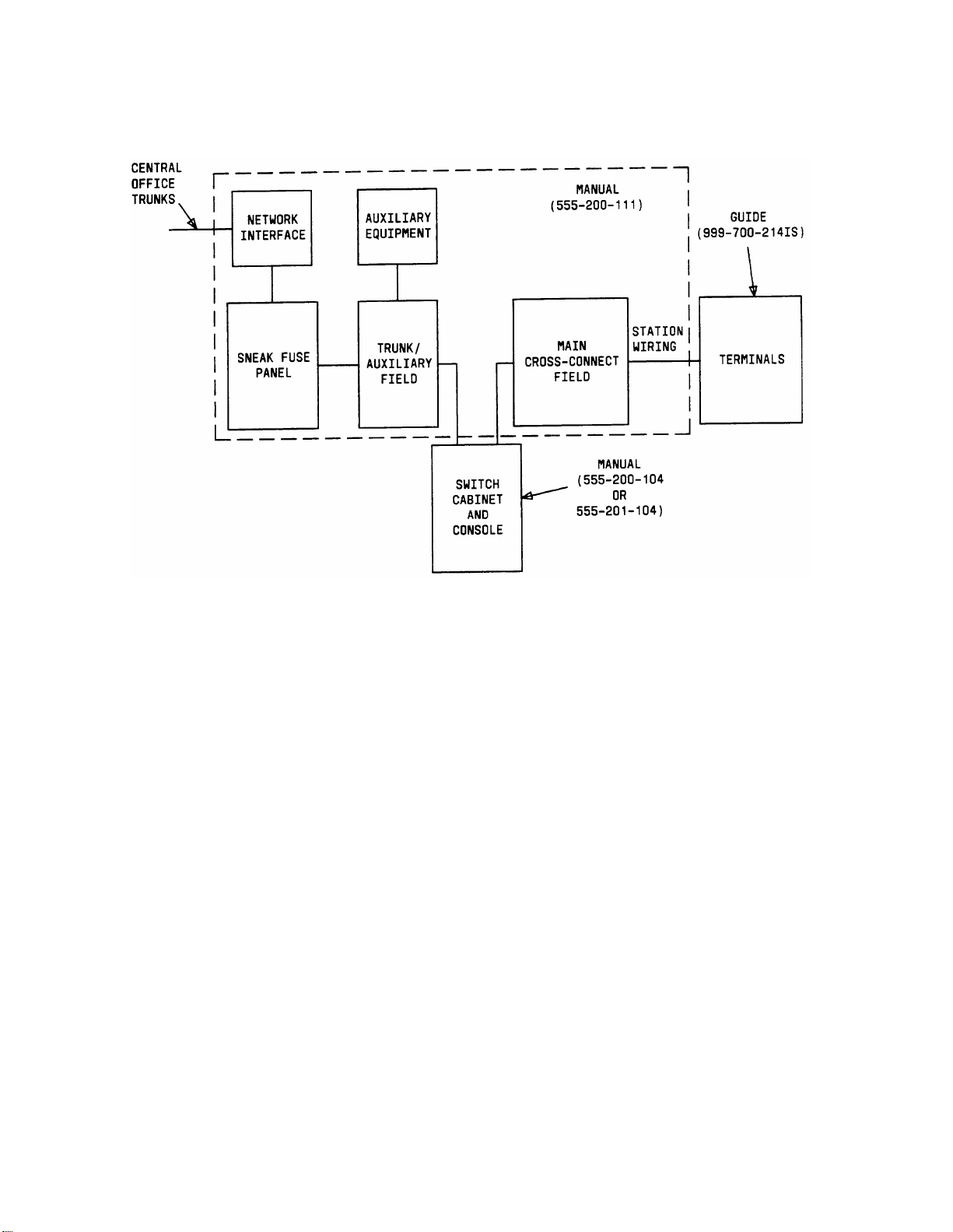
Figure 1-1. Documentation Block Diagram
1-2
Page 7

ORGANIZATION
This guide is organized into five sections:
●
SECTION 1—INTRODUCTION
Contains an overview of the system Uniform Wiring Plan and presents
general guidelines on hardware selection and manual organization.
●
SECTION 2—Z100-TYPE MODULAR HARDWARE
Contains an explanation of Z100-type and associated hardware, job planning,
equipment ordering codes, and how to install the hardware.
●
SECTION 3—110-TYPE HARDWARE
Contains an explanation of 110-type and associated hardware, job planning,
equipment ordering codes, and how to install the hardware.
●
SECTION 4—66-TYPE HARDWARE
Contains an explanation of 66-type and associated hardware, job planning,
equipment ordering codes, and how to install the hardware.
●
SECTION 5—GLOSSARY
Contains a brief description of some of the terms used in this guide.
●
SECTION 6—INDEX
Contains a permuted index.
Use of Guide
This guide will be helpful in planning, designing, and installing a cost-effective wiring
installation that allows moves, changes, and additions to be made quickly and easily. To
make the best use of this guide, take the time to read it thoroughly and become familiar
with its contents and organization. For quick access to information needed to answer most
questions, simply refer to the table of contents and locate the specific item in question.
To answer questions requiring more information than this guide contains, consult the
documents listed previously in this introduction section. If you need additional help, contact
the Premises Services Consultant (PSC).
For further technical assistance, the recommended channel for AT&T System Technicians is
as follows:
1.
Contact your Field Assistance and Support Team (FAST).
2.
If a satisfactory answer is not obtained from the FAST center, contact your
supervisor.
3.
Your supervisor should contact the regional staff, if necessary.
1-3
Page 8

Equipment
Most of the items specified in this guide are available through your local AT&T Information
Systems Marketing Branch Office (MBO). However, some common use hardware items may
have to be obtained from other sources.
GENERAL
Station wiring has a significant role in today’s customers’ information systems.
Technological innovations have enabled both voice and data transmission to be provided
through communications system wiring and have simplified wiring by significantly reducing
the number of cable pairs required by terminals with enhanced feature options.
This guide provides planning, ordering, and installation guidelines for a system Uniform
Wiring Plan (Figures 1-2 and 1-3) using Z100-, 110-type, or 66-type hardware.
The system switch ports for data and voice terminals require three pairs of wire per circuit.
Voice terminal adjuncts require an additional pair for remote powering. To provide
maximum flexibility for voice terminal changes, rearrangements, and powering, all data and
voice terminal information outlets are wired with 4-pair cable. With proper administration,
this will allow any terminal to be located at any information outlet.
1-4
Page 9
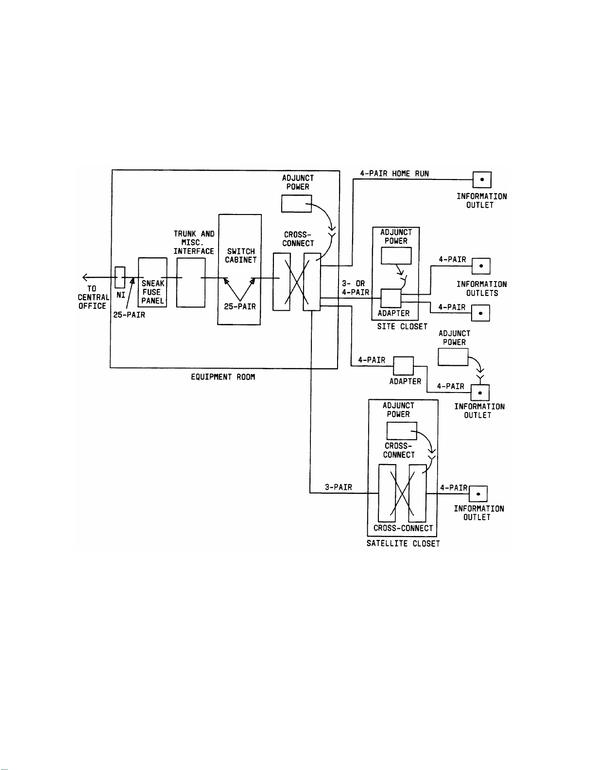
Figure 1-2. System Uniform Wiring Plan
1-5
Page 10
1-6
Figure 1-3. Sample Uniform Wiring Installation
Page 11

CROSS-CONNECT HARDWARE SELECTION
The following cross-connect hardware for new wiring installations is listed for the system.
Following each list item are considerations that should help to determine the appropriate
selection.
Z100-Type Hardware
1.
●
Designed particularly for customer participation in cross-connect
administration due to patch cord design
Does not require technical skills for cross-connect administration
●
Firm quote price list for all installations up to 150 stations
●
110P Hardware
2.
●
Customer participation in cross-connect administration due to patch cord
design
Requires some amount of technical skill for cross-connect administration
●
3. 110A Hardware
Not designed for customer participation in cross-connect administration—
●
requires technically skilled personnel due to use of jumper wires
●
Less expensive material cost than the patch cord systems, but more
expensive installation and administrative labor cost
66-Type Hardware
4.
● Not designed for customer participation in cross-connect administration—
requires technically skilled personnel due to use of jumper wires
Less expensive material cost than the patch cord systems, but more
●
expensive installation and administrative labor cost
Obviously, the customer’s degree of interest and preference for administering his or her own
cross-connections (because of likely lower total annual costs, as well as preference for
administering his or her cross-connect field at his or her convenience) should be given
primary consideration in recommending cross-connect hardware.
WIRING HARDWARE CHANGES
All jobs engineered by Premises Services Consultants (PSCs) based on customer
requirements and preferences should not be redesigned by the Field Services Organization
(FSO) without approval by the PSC/Marketing Branch Office (MBO). A change order must
be issued to affect billing.
PLANNING
The following brief introductory information will help you design a uniform wiring plan with
sufficient growth potential. The plan is flexible, simple, easy to administer, and reasonable
in cost.
1-7
Page 12

Job Aids
Blueprints (floor plans) are an important tool when planning, designing, and installing
station wiring. The floor plans (Figure 1-4) provide a complete view of all conduit and other
cabling facilities placed during construction of the building. These facilities should be
considered when planning site or satellite locations and cabling.
Terminals
The number of information outlets to be installed per terminal location should be
determined by your requirements. It may also be advantageous to initially install any
additional information outlets that may be required for future growth or terminal
rearrangements.
To begin designing the station wiring, indicate the following information on the floor
plan(s):
● Location of each information outlet and associated terminal type if known (analog,
hybrid, or digital)
●
Any associated terminal adjuncts or modules and the required powering
arrangements.
1-8
Page 13
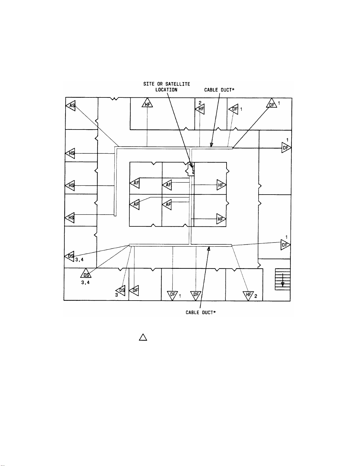
* AN OPTION TO THE CABLE DUCT SHOWN IS TO RUN CABLES (PLENUM-APPROVED, IF
APPROPRIATE OR REQUIRED) ABOVE A DROP/FALSE CEILING.
- INFORMATION OUTLET LOCATION
A-
ANALOG TERMINAL DEVICE
H -
HYBRID TERMINAL DEVICE
D -
DIGITAL TERMINAL DEVICE
S-
SURFACE MOUNTED INFORMATION OUTLET
F-
FLUSH MOUNTED INFORMATION OUTLET
1 -
SPEAKERPHONE
2 -
AMPLIFIED HEADSET
3 -
CALL COVERAGE MODULE
4 -
FUNCTION KEY MODULE
5 -
DISPLAY MODULE
Figure 1-4. Sample Floor Plan With Terminal Locations Marked
1-9
Page 14

Site or Satellite Closets
When determining the site or satellite closets, use the following information as a guide.
Indicate the locations on the floor plan.
Keep the number of locations to a minimum.
a.
To minimize the station wiring distances, centrally locate the site or satellite
b.
closets among the information outlets.
Site or satellite closets should be easily accessible and contain sufficient ac power
c.
outlets. Terminals equipped with adjuncts that require power can be remotely
powered from a site or satellite location as well as from the main equipment room
or at information outlets. The distance between the power supply and the terminal
cannot exceed 250 feet (76.2 m) using 24-gauge wire.
Locks should be provided for the site or satellite closet to prevent tampering.
d.
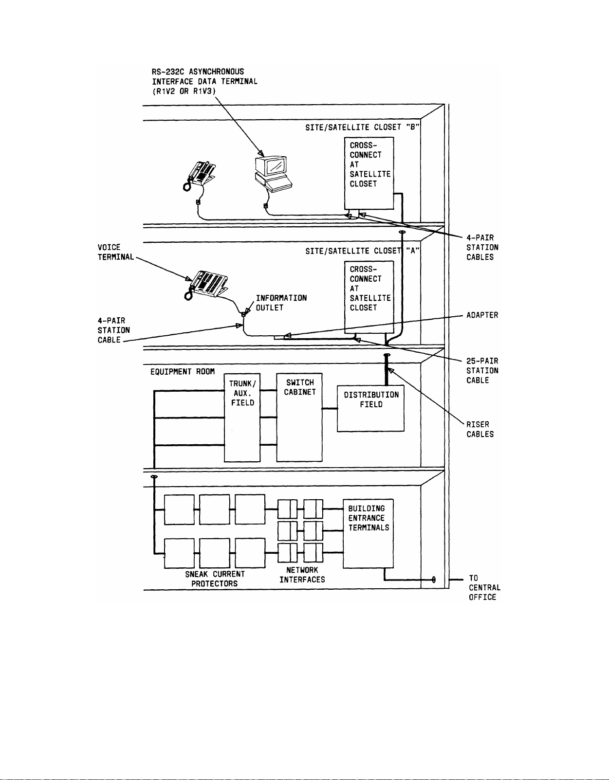
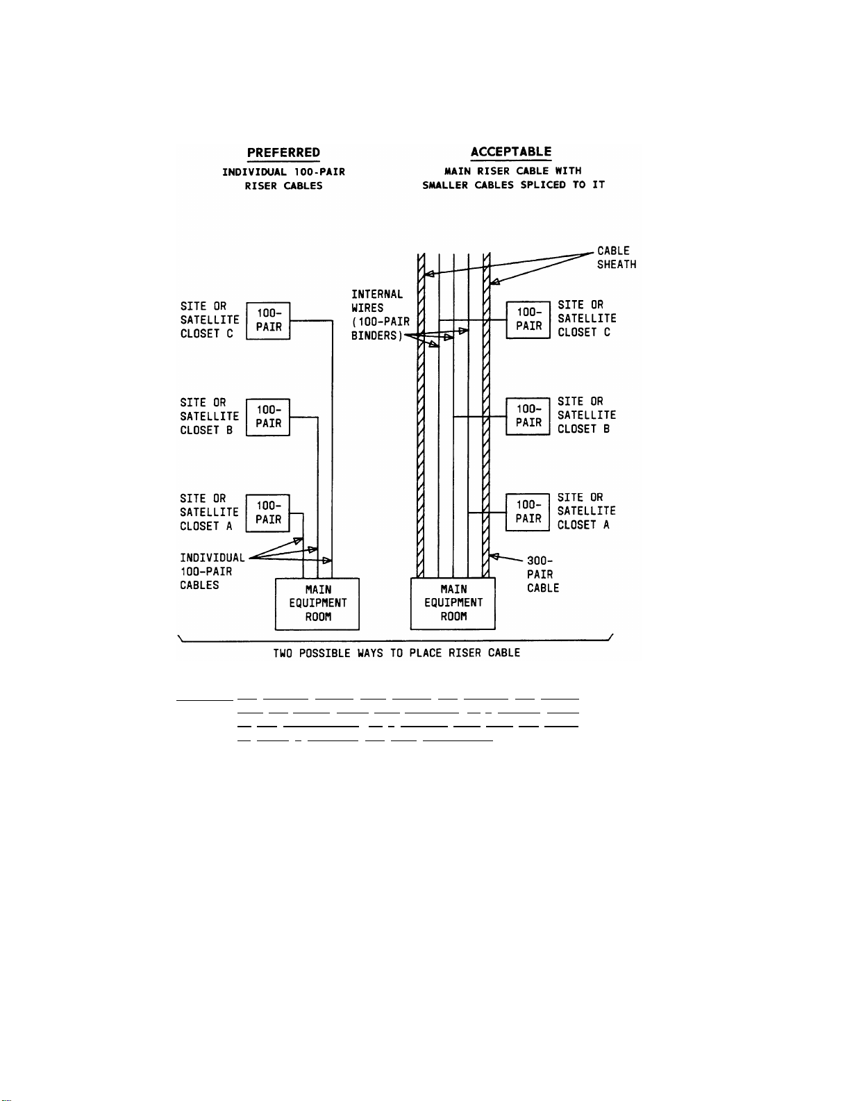
Cabling Facilities
The method of riser cable distribution between the main equipment room and the site or
satellite closets is usually determined by the type of cabling facilities (riser closets, conduit
size, cabling shafts, etc.) placed during construction of the building (Figure 1-5).
a.
The preferred arrangement is to have individual cables supply each site or satellite
closet.
b.
A second method is to have one or two large cables supply all the site or satellite
closets. This method requires smaller cables to be installed between the main riser
cable and the site or satellite closet. These smaller cables are spliced into the main
cable.
Determine the type of cabling required and mark the type and routing on the blueprint or
floor plan. Also indicate any additional cabling facilities required for riser and terminal
cabling.
1-10
Page 15
CAUTION:
THE UNIFORM WIRING PLAN SHOULD NOT CONTAIN ANY BRIDGE
TAPS (AN UNUSED CABLE PAIR CONNECTED TO A WORKING CABLE
OR THE CONTINUATION OF A WORKING PAIR PAST THE POINT
AT WHICH A TERMINAL HAS BEEN CONNECTED).
Figure 1-5. Riser Cable Placement
1-11
Page 16

2. Z100-TYPE HARDWARE—SYSTEM 75 AND SYSTEM 75 XE INSTALLATIONS
CONTENTS
Page
GENERAL
Z100-TYPE HARDWARE
Connector Modules
Z100A1 Connector Module
Z100B1 Connector Module
Connecting Units
Cords
ZD6A-87 Patch Cords
ZD2A-87-10 Power Adapter Cords
Associated Hardware
Cable Slack Managers
General
Z113A Housing
Z114A Housing
NETWORK INTERFACES
RJ21X Network Interfaces
RJ2GX Network Interfaces
1.544 Mbps Digital Service Interfaces
SNEAK FUSE PANELS
575-4 Sneak Current Fuse Assembly
TRUNK/AUXILIARY FIELD
Cable Access Panels and Emergency Transfer Units
400A Apparatus Mounting
400B Apparatus Mounting
400C Apparatus Mounting
2-1
2-2
2-2
2-4
2-4
2-7
2-10
2-10
2-11
2-12
2-12
2-12
2-13
2-13
2-15
2-15
2-15
2-15
2-15
2-15
2-16
2-17
2-17
2-17
2-17
TRUNK CONCENTRATOR CABLES
WP-90929, List 2, Cable Assembly
WP-90929, List 4, Cable Assembly
16-PORT ANALOG LINE BOARD ADAPTER CABLE
4-PORT MET LINE BOARD CONCENTRATOR CABLE
ADJUNCT POWER UNITS
Individual Power Supplies
-i-
2-20
2-20
2-20
2-23
2-24
2-24
2-24
Page 17

Bulk Power Supply
346 Modular Bulk Power Supply
EQUIPMENT ROOM DESIGN
Typical System Equipment Room Floor Plans
General
Typical Floor Plans
Single-Section Cross-Connect Field
Mult-Section Cross-Connect Field
Wall Space Requirements
Single-Section Cross-Connect Field
Multi-Section Cross-Connect Field
Equipment Requirements
Connector Module, Patch Cord, and Cable Slack Manager
Requirements
Cable Access Panel Requirements
Trunk Circuit Capacities
Selecting the Cable Access Panel
EQUIPMENT ROOM HARDWARE AND CABLING INSTALLATION
Hardware Installation
Installing the Cross-Connect Field
Installing Cable Slack Managers
Labeling the Cross-Connect Field
Main Cross-Connect Field
Multi-Section Cross-Connect Field
2-26
2-26
2-29
2-29
2-29
2-29
2-29
2-33
2-34
2-34
2-34
2-35
2-35
2-36
2-36
2-36
2-38
2-38
2-38
2-40
2-41
2-42
2-47
Installing the Cable Access Panels (CAPs)
Labeling the Cable Access Panel
Installing the Sneak Fuse Panels
Cable Installation
Labels
Routing Cable Guidelines
General
Routing Cables From Switch Cabinet to Cross-Connect Field
Routing Cables From Cable Access Panel to Switch Cabinet
Installing Control Carrier Outputs Cable
Installing Trunk Cables Between Network Interface and System
Cabinet
Installing Coupled Bonded Conductor Grounding
-ii-
2-50
2-51
2-60
2-60
2-60
2-61
2-62
2-63
2-64
2-65
2-66
2-73
Page 18

Installing Cables Between Switch Cabinet and the Cross-Connect
Field
Installing Cables Between Cross-Connect Field and Auxiliary
Cabinet
STATION WIRING DESIGN
Description
Information Outlets
Station Cables
Closets
Site Locations
Satellite Locations
Station Circuit Distribution From Equipment Room
4-Pair Station Circuits
3-Pair to 4-Pair Station Circuits
Layout
Locating Information Outlets
Locating Satellites and Sites
Adapter Requirements
2-74
2-78
2-78
2-78
2-78
2-78
2-80
2-80
2-82
2-83
2-83
2-83
2-88
2-88
2-88
2-88
Z100A1 Connector Module Requirements
Sizing 4-Pair Station Cables (DIW)
Sizing 25-Pair and Multiple 25-Pair Station Cables
3-Pair Station Cable Circuits
4-Pair Station Cable Circuits
STATION WIRING AND ASSOCIATED HARDWARE INSTALLATION
Installing the Station Cables
Installing Z100-Type Hardware at Satellite Locations
Labeling
Installing the Information Outlets
ADJUNCT POWERING
Adjunct Powering From the Equipment Room
Adjunct Powering From Satellite Locations
Adjunct Powering From Site Locations
Adjunct Powering From Information Outlets
PATCH CORD INSTALLATION AND ADMINISTRATION
Equipment Room Cross-Connect Field
Installing Patch Cords
Removing Patch Cords
2-88
2-88
2-88
2-88
2-89
2-89
2-89
2-92
2-93
2-95
2-96
2-96
2-96
2-96
2-100
2-102
2-105
2-105
2-105
-iii-
Page 19

Installing and Removing Power Adapter Cords
2-106
Satellite Locations
1-Point Administration
2-Point Administration
MISCELLANEOUS WIRING INSTALLATION
Installing Attendant Console
Installing Selector Console
Installing INADS (Initialization and Administration System) Interface
Installing DS1 Tie Trunks
Collocated DS1 Tie Trunks
DS1 Tie Trunks Using 551-Type CSU
Installing Customer-Provided Alarm—System 75 XE Only
Installing Off-Premises Terminal Wiring
Installing Out-of-Building Terminal Wiring
Analog Out-of-Building Terminals
Digital Out-of-Building Terminals
Installing Emergency Transfer Units and Terminals
2-106
2-107
2-107
2-107
2-107
2-111
2-112
2-114
2-114
2-114
2-116
2-116
2-118
2-118
2-119
2-122
574-5 Power Transfer Unit
Z1A Emergency Transfer Unit
Installing External Ringing
Installing Queue Warning Indicator
AUXILIARY EQUIPMENT INSTALLATION
Auxiliary Equipment Description
Installing Loudspeaker Paging and Music-on-Hold
Installing Loudspeaker Paging Access—278A Paging Adapter
Installing Loudspeaker Paging Access—89A Control Unit
PagePac PAGING SYSTEM
PagePac 20
PagePac VS
PagePac 50/100/200
Installing Music-on-Hold Access
Installing Loudspeaker Paging With Background Music
Installing Recorded Announcement Equipment
2-122
2-130
2-137
2-138
2-139
2-139
2-140
2-142
2-144
2-146
2-146
2-146
2-146
2-152
2-156
2-157
Digital Announcer
Installing Audichron Wake-Up Announcement System—R1V3 Only
Installing Dial Dictation Equipment
-iv-
2-161
2-162
2-165
Page 20

Installing 3270 Data Modules
2-166
Installing Processor Data Modules (PDMs)
Installing Applications Processor Interface—System 75 Only
Installing Audio Information Exchange (AUDIX) Interface—V3
Only
Installing Call Management System (CMS) Interface—V3 Only
Installing Distributed Communications System (DCS)—V2 and V3
Property Management System Interface—V3 Only
Installing Customer-Provided Terminal Using Asynchronous Data Units
(ADUs)
Installing Station Message Detail Recording Interface
2-168
2-171
2-173
2-173
2-173
2-174
2-174
2-176
-v-
Page 21

LIST OF FIGURES
Figure 2-1
Figure 2-2
Figure 2-3
Figure 2-4
Figure 2-5
Figure 2-6
Figure 2-7
Figure 2-8
Figure 2-9
Figure 2-10
Figure 2-11
Figure 2-12
Figure 2-13
Figure 2-14
Figure 2-15
Figure 2-16
Block Diagram of System 75 or System 75 Reinstallation
Station Wiring Alternatives
Z100-Type Support and Panel
Z100A1 Connector Module 2-5
Z100B1 Connector Module 2-6
Z100-Type Connecting Units
Connecting Unit Installation
Connecting Unit Removal
ZD6A-87 Patch Cord 2-11
ZD2A-87-10 Power Adapter Cord 2-12
Cable Slack Managers 2-14
Model 575-4 Sneak Fuse Panel 2-16
Cable Access Panel (400C Apparatus Mounting)
Cable Access Panel (Functional Diagram)
Trunk Concentrator Cables (WP-90929, Lists 2 and 4, Cable
Assemblies) 2-21
16-Port Analog Line Board Adapter Cable (853B Adapter)
2-1
2-2
2-3
2-8
2-9
2-10
2-18
2-19
2-24
Figure 2-17
Figure 2-18
Figure 2-19
Figure 2-20
Figure 2-21
Figure 2-22
Figure 2-23
Figure 2-24
Figure 2-25
Figure 2-26
Figure 2-27
Individual Power Supplies
AC Power Strip
346 Modular Bulk Power Supply
346A1 Power Panel Circuit Breaker Locations
Typical Single-Section Cross-Connect Field Installation
(Approximately 288 Station Capacity Illustrated)
Typical 2-Carrier System 75 Cabinet or 2-Cabinet System 75 XE Floor
Plan
Typical 5-Carrier System 75 Cabinet or 3- or 4-cabinet System 75 XE
Floor Plan
Typical Multi-Section Cross-Connect Field Installation (Approximately
576 Station Capacity Illustrated)
Typical 5-Carrier Cabinet Floor Plan Using a Multi-Section CrossConnect Field
Cross-Connect Field and Cable Access Panel Installation
System Label Graphic Symbols and Designation
Nomenclature
2-25
2-25
2-27
2-28
2-30
2-31
2-32
2-33
2-34
2-39
2-41
-vi-
Page 22

Figure 2-28
Cross-Connect Field Layout
2-42
Figure 2-29
Figure 2-30
Figure 2-31
Figure 2-32
Figure 2-33
Figure 2-34
Figure 2-35
Figure 2-36
Figure 2-37
Figure 2-38
Figure 2-39
Figure 2-40
Figure 2-41
Figure 2-42
Figure 2-43
Port Labels
4-Pair Station Appearance Labels
3-Pair Station Appearance Labels
Auxiliary Labels
Section TIE Labels
Clear Plastic Label Holder (188UT1-50 Strip Designation)
Control Carrier Outputs (AUXILIARY Label)
System Port Circuit Appearances and Trunk Labels
System Port Circuit Appearances and Auxiliary Circuit
Labels
Z1A Emergency Transfer Unit Labels
574-5 Power Transfer Unit Labels
"X" Connector Label 2-60
Equipment Room Cabling Labels 2-61
Self-Stick Label Installation on 25-Pair Cable Connector
Cable Routing Through Cable Slack Manager—1-Cabinet
Installation
2-43
2-44
2-45
2-46
2-47
2-51
2-53
2-55
2-56
2-58
2-59
2-61
2-62
Figure 2-44
Figure 2-45
Figure 2-46
Figure 2-47
Figure 2-48
Figure 2-49
Figure 2-50
Figure 2-51
Figure 2-52
Figure 2-53
Figure 2-54
Figure 2-55
Figure 2-56
Figure 2-57
Cable Routing From Switch Cabinet to Cross-Connect Field and Cable
Access Panel
Typical Port Cable Installation at Switch Cabinet 2-64
Control Carrier Outputs (AUXILIARY Connector)—System
75
Control Carrier Outputs (AUXILIARY Connector)—System 75
XE
System 75 2-Carrier Slot Addresses
System 75 5-Carrier Slot Addresses
System 75 XE Carrier Slot Addresses
Installing Concentrator Cables Between the CAP and the Switch
Cabinet
Coupled Bonded Conductor Grounding Installation
Connector Module Flex Tab Latch Locations
25-Pair Cable Routing Through Connector Module
4-Pair Single Modular Plug-Ended Station Cable 2-79
Example of Extending 4-Pair Station Cables
258A and BR2580A Adapters 2-81
2-63
2-65
2-66
2-69
2-70
2-71
2-72
2-74
2-76
2-77
2-80
Figure 2-58
356A Adapter
2-82
-vii-
Page 23

Figure 2-59
4-Pair Circuit Distribution and Connectivity from Equipment Room
Cross-Connect Field Using Z100A1 Connector Modules
2-83
Figure 2-60
Figure 2-61
Figure 2-62
Figure 2-63
Figure 2-64
Figure 2-65
Figure 2-66
Figure 2-67
Figure 2-68
Figure 2-69
Figure 2-70
3-Pair to 4-Pair Circuit Distribution and Connectivity From
Equipment Room (Z100B1 Connector Modules Used at Cross-Connect
Field and Z100A1 Connector Modules Used at Satellite
Location)
3-Pair to 4-Pair Circuit Distribution and Connectivity From
Equipment Room (Z100B1 Connector Modules Used at Cross-Connect
Field and 356A adapter Used at Site Location)
25-Pair Station Cable Labels
Multiple 25-Pair Station Cable With Factory-Installed Staggered
Fingers Connected to a Connector Module
4-Pair Station Wiring Labeling From Equipment Room to Information
Outlet
Typical Satellite Installation
Satellite Location Layout
3-Pair to 4-Pair Station Wiring Labeling From Equipment Room to
Information Outlet
Typical 8-Pin Modular Information Outlets
Remote Powering From a Z100A1 Connector Module Located at the
Equipment Room or Satellite Location
Remote Powering From a 258A Adapter in a Site Closet
2-84
2-85
2-89
2-90
2-91
2-92
2-93
2-94
2-95
2-97
2-98
Figure 2-71
Figure 2-72
Figure 2-73
Figure 2-74
Figure 2-75
Figure 2-76
Figure 2-77
Figure 2-78
Figure 2-79
Figure 2-80
Figure 2-81
Figure 2-82
Figure 2-83
Figure 2-84
Remote Powering From a 356A Adapter in a Site Closet
Typical Local Powering From a 400B2 Adapter—Flush-Mounted
Information Outlet
Typical Local Powering From a 400B2 Adapter—Surface-Mounted
Information Outlet
Port Assignment Record Form
1-Point Administration
2-Point Administration
Patch Cord Plug Release Tab Removal Location
Connections for Attendant Console
Wiring Required at Cable Access Panel for Attendant Console Remote
Powering From Switch Cabinet—System 75 Only
Selector Console Installation
Connections at Cable Access Panel for INADS Trunk
Connections for DS1 Tie Trunks Between 2 System 75s or System 75
XEs
Connections for DS1 Tie Trunks Using 551 T1 CSU
Connections for Off-Premises Terminals
2-99
2-100
2-101
2-103
2-104
2-104
2-107
2-109
2-110
2-111
2-113
2-115
2-115
2-117
Figure 2-85
Connections for One to Eight Out-of-Building Analog Voice Terminals
Only
-viii-
2-120
Page 24

Figure 2-86
Connections for Each Group of Eight Out-of-Building Analog Voice
Terminals
2-121
Figure 2-87
Figure 2-88
Figure 2-89
Figure 2-90
Figure 2-91
Figure 2-92
Figure 2-93
Figure 2-94
Figure 2-95
Figure 2-96
Figure 2-97
574-5 Power Transfer Unit Option Switches
Connections at Cable Access Panel for Voice Terminal Used Only for
Emergency Transfer—574-5 Power Transfer Unit
Connections at Cable Access Panel for Voice Terminal Used for
Emergency Transfer and as Normal Extension—574-5 Power Transfer
Unit
Connections at Cable Access Panel for Optional DID Make-Busy
Trunk—574-5 Power Transfer Unit
Connections at Cable Access Panel for Voice Terminal Used Only for
Emergency Transfer (Ground Start Trunks)—Z1A Emergency
Transfer Unit
Connections at Cable Access Panel for Voice Terminal Used for
Emergency Transfer and as Normal Extension (Ground Start
Trunks—Z1A Emergency Transfer Unit)
Connections at Cable Access Panel for Optional DID Make-Busy
Trunk—Z1A Emergency Transfer Unit
Ground Wiring Example (Three Voice Terminals Used Only for
Emergency Transfer)
Ground Wiring Example (Five Voice Terminals Used for Emergency
Transfer and as Normal Extensions)
Ground Start Key Installation
Connections for External Ringing or Queue Warning
Indicator
2-123
2-125
2-127
2-129
2-131
2-133
2-135
2-136
2-136
2-137
2-138
Figure 2-98
Figure 2-99
Figure 2-100
Figure 2-101
Figure 2-102
Figure 2-103
Figure 2-104
Figure 2-105
Figure 2-106
Figure 2-107
Figure 2-108
Figure 2-109
Connections for Loudspeaker Paging and Music-on-Hold
Connections for Loudspeaker Paging Zone—278A Paging
Adapter
Connections for Loudspeaker Paging Zone—89A Control Unit
Connections for PagePac 20 Without Zone-Mate 9 or 39
Connections for PagePac 20 With Zone-Mate 9 or 39
Connections for PagePac VS
Connections for PagePac 50/100/200 Amplicenter Only
Connections for PagePac 50/100/200 System
Connections for FCC Registered Equipment Provided for Music-on-
Hold/Dial Dictation Equipment (Auxiliary Access)
Connections for Non-FCC Registered Equipment Provided for Music-
on-Hold/Dial Dictation Equipment (Auxiliary Access)
Loudspeaker Paging With Background Music Connections—278A
Adapter
Loudspeaker Paging With Background Music Connections—89A
Control Unit
2-141
2-143
2-145
2-147
2-148
2-149
2-150
2-151
2-153
2-155
2-156
2-157
-ix-
Page 25

Figure 2-110
Connections for FCC Registered Equipment Provided for Recorded
Announcement/Dial Dictation Equipment (Analog Access)
2-158
Figure 2-111
Figure 2-112
Figure 2-113
Figure 2-114
Figure 2-115
Figure 2-116
Figure 2-117
Figure 2-118
Figure 2-119
Figure 2-120
Figure 2-121
Connections for Non-FCC Registered Recorded Announcement/Dial
Dictation Equipment (Analog Access)
Connections to Digital Announcer Located in Auxiliary
Cabinet
Connections for Analog Line Port to Wake-Up Announcement
Unit
Connections for Auxiliary Trunk Circuit Pack to Wake-Up
Announcement Unit
Connections for Power Unit to Wake-Up Announcement Unit
Connections for 3270A or 3270T Data Module
Connections for 3270C Data Module
Connections for PDMs in Data Mounting—Through Cable Access
Panel
Connections for PDMs in Data Mounting—Through Cross-Connect
Field
Connections for Individual PDMs
Connections at Cable Access Panel for Applications Processor
Alarms
2-160
2-162
2-164
2-164
2-165
2-167
2-167
2-169
2-170
2-171
2-172
Figure 2-122
Figure 2-123
Figure 2-124
Figure 2-125
Connections to ADU for Data Terminal Equipment (R1V2 or
R1V3)
SMDR Cabling for Data Terminal Equipment
SMDR Cabling for On-Premises Data Communications
Equipment
SMDR Cabling for a Remote Host
2-175
2-176
2-177
2-177
-x-
Page 26

LIST OF TABLES
TABLE 2-A WP-90929, List 2, Cable Assembly Wiring
TABLE 2-B WP-90929, List 4, Cable Assembly Wiring
TABLE 2-C Individual Power Supply Adjunct and Distance Limitations
TABLE 2-D 346A Power Unit Adjunct and Distance Limitations
TABLE 2-E Z100 Cross-Connect Hardware Requirements
TABLE 2-F Carrier Lead Appearance on Connector
TABLE 2-G System Wiring
2-22
2-23
2-26
2-28
2-35
2-67
2-86
-xi-
Page 27
Z100-TYPE HARDWARE
2. Z100-TYPE HARDWARE—SYSTEM 75 OR SYSTEM 75 XE INSTALLATIONS
GENERAL
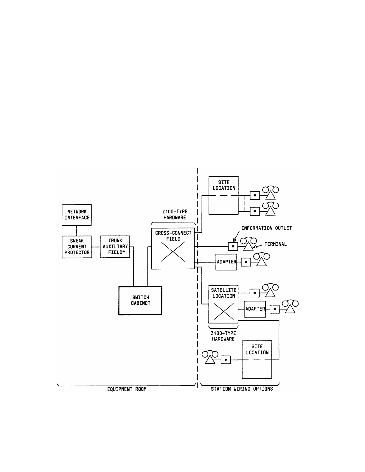
Figure 2-1 shows the equipment required to install a System 75 or System 75 XE. A
description and explanation of each piece of equipment follows. Ordering information is
provided at the end of each description.
The sites shown in Figure 2-1 are physical locations (closets) for pass-through connections
where adjunct power may be applied. The satellite is a physical location (closet) where
cross-connect administration can take place and adjunct power may be applied.
*
PROVIDED BY THE CABLE ACCESS PANEL (CAP), 110-TYPE
HARDWARE OR 66-TYPE HARDWARE
Figure 2-1. Block Diagram of System 75 or System 75 XE Installation
2-1
Page 28
Z100-TYPE HARDWARE
Z100-TYPE HARDWARE
As shown in Figure 2-1, Z100-type hardware is used for the cross-connect field and for
optional satellite locations. The Z100 hardware consists of the following:
●
Connector Modules
Connecting Units
●
Cords (Anti-Snag Modular Plug-Ended Patch Cords and Power Adapter Cords).
●
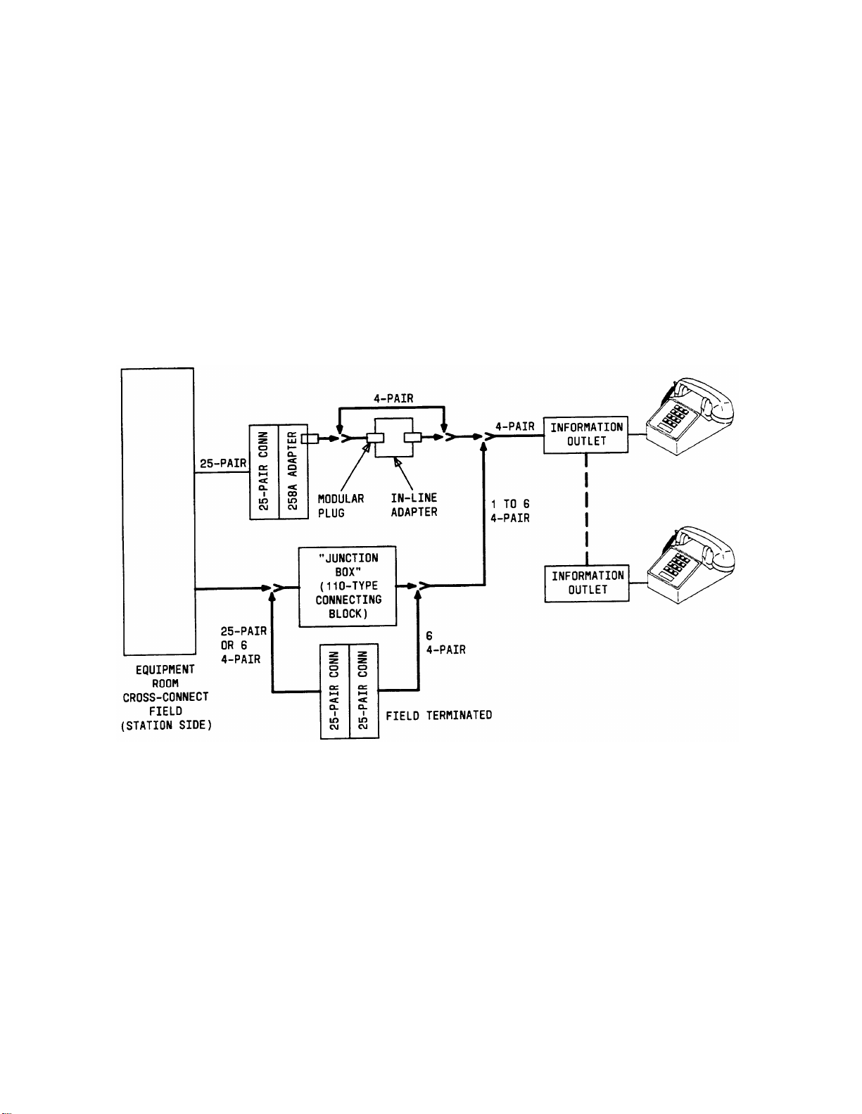
Hard-wired (punch-down) connections are not used with the Z100 hardware unless field-
applied 25-pair connectors, modular plugs, or external "junction boxes" (punch-down to 50pin miniature ribbon connector) are used (see Figure 2-2).
Figure 2-2. Station Wiring Alternatives
Connector Modules
Connectorized 25-pair cables terminate on the connector modules. Anti-snag modular plugended patch cords are used to cross-connect the circuits.
The connector modules are preassembled. Each connector module is 5 inches (12.7 cm) wide
and approximately 44 inches (111.8 cm) high. The hardware making up the assembly
consists of one Z9A support, one Z2A jack panel, seven connecting units, seven Z5A
retainers, and one MET/RJ25C connector adapter (test jack).
2-2
Page 29
Z100-TYPE HARDWARE
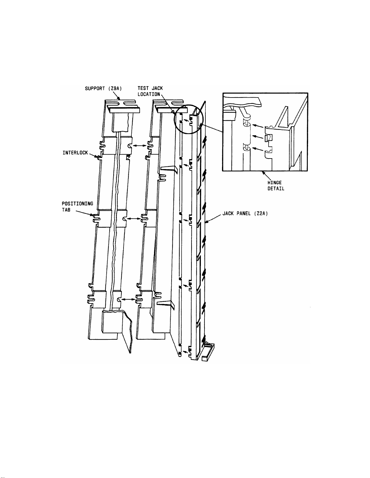
Figure 2-3 shows the connector module support and jack panel. The support has tabs that
allow adjacent connector modules to snap and interlock together to form cross-connect fields.
An additional support is required for each cross-connect filed to provide a patch cord guide
for the last connector module in the field.
Figure 2-3. Z100-Type Support and Panel
The connecting units and Z5A retainers are located inside the jack panel. The Z5A retainers
located at the back of the jack panel snap closed to lock the mating connectors of the 25-pair
cables in place.
2-3
Page 30

Z100-TYPE HARDWARE
The MET/RJ25C connector adapter (test jack) is located at the top of the Z9A support. An
anti-snag modular plug-ended patch cord can be plugged from it into the port jack and a
terminal connected to the station jack to test either a circuit coming from the switch or the
terminal.
There are two preassembled Z100-type connector modules available with connecting units.
The connector modules are identical except for the connecting units provided.
Z100A1 Connector Module
The Z100A1 connector module (see Figure 2-4) contains four Z200A1 connecting units and
three Z201A1 connecting units. The Z100A1 connector module is used at either the crossconnect field or at satellite locations when 4-pair station circuits are provided from the
equipment room or satellite closet to the station wiring. Each Z100A1 connector module has
a capacity of twenty-four 4-pair station circuits and twenty-four 3-pair port or station
circuits.
Z100B1 Connector Module
The Z100B1 connector module (see Figure 2-5) contains four Z203A1 connecting units and
three Z201A1 connecting units. The Z100B1 connector module is used at the cross-connect
field when 3-pair station circuits are provided from the equipment room to the station
wiring. Each Z100B1 connector module has a capacity of thirty-two 3-pair station circuits
and twenty-four 3-pair port circuits. This connector module may also be used if connections
are required for off-premises stations in an otherwise 4-pair station cross-connect field
arrangement.
The following is a listing of ordering information for the connector modules. Ordering
information for the individual connecting units is provided under the heading Connecting
Units in this manual.
CONNECTOR MODULE ORDERING INFORMATION
Description
Z100A1 Connector Module
Z100B1 Connector Module
Z2A Jack Panel
Z5A Retainer
Z9A Support
MET/RJ25C Connector Adapter
Comcode
103 961 157
103 961 165
103 961 231
103 961 215
103 961 249
403 826 928
2-4
Page 31

Z100-TYPE HARDWARE
Figure 2-4. Z100A1 Connector Module
2-5
Page 32

Z100-TYPE HARDWARE
2-6
Figure 2-5. Z100B1 Connector Module
Page 33

Z100-TYPE HARDWARE
Connecting Units
The four connecting units (Figure 2-6) that can be used in the connector modules are as
follows:
● Z200A1—Used for connectorized station cables (4-pair station circuits from
equipment room or satellite locations).
Z201A1—Used in the cross-connect field for the connectorized switch cables and in
●
satellite locations for connectorized station cables (3-pair station circuits from the
equipment room).
Z202A1—Used for Standard Serial Interface (SSI) port circuits from an Applications
●
Processor (AP) to data terminals only.
●
Z203A1—Used for connectorized station cables (3-pair station circuits from the
equipment room).
The Z202A1 connecting unit is not available in the preassembled connector modules. It can
be used as a replacement in the Z100A1 or Z100B1 connector modules. Figures 2-7 and 2-8
show how the connecting units are installed and removed.
CONNECTING UNIT ORDERING INFORMATION
Description
Z200A1 Connecting Unit
Z201A1 Connecting Unit
Z202A1 Connecting Unit
Z203A1 Connecting Unit
Comcode
103 961 256
103 961 264
103 961 272
103 961 280
2-7
Page 34

Z100-TYPE HARDWARE
(USED WITH SSI CIRCUITS ONLY)
Figure 2-6. Z100-Type Connecting Units
2-8
Page 35

Z100-TYPE HARDWARE
NOTE:
HOLD Z5A RETAINER OUT OF THE WAY WHILE
INSERTING (OR REMOVING) CONNECTING UNIT.
Figure 2-7. Connecting Unit Installation
2-9
Page 36

Z100-TYPE HARDWARE
PUSH CONNECTING UNIT
OUT WHILE PRYING
JACK PANEL SLIGHTLY
OPEN WITH SCREWDRIVER.
Figure 2-8. Connecting Unit Removal
Cords
ZD6A-87 Patch Cords
The ZD6A-87 patch cords (Figure 2-9) equipped with 3-pair anti-snag modular plugs are used
with the connector modules to provide cross-connections. This 3-pair patch cord can be
connected to both the 3- and 4-pair jacks on connecting units. Four patch cord lengths are
available. The lengths are identified by the color of the molded plastic modular plugs on
each end and can be ordered as follows (see Note):
Note: See Equipment Requirements for additional patch cord ordering quantities.
2-10
Page 37

PATCH CORD ORDERING INFORMATION
Z100-TYPE HARDWARE
Cord
ZD6A-87
ZD6A-87
ZD6A-87
ZD6A-87
Modular Plug
Color
Length
Clear 7 ft (2.1 m)
Yellow
Blue
Black
10 ft (3.0 m)
12 ft (3.7 m)
14 ft (4.3 m)
Comcode
(1 per package)
103 944 872
103 944 898
103 944 914
103 944 948
Figure 2-9. ZD6A-87 Patch Cord
ZD2A-87-10 Power Adapter Cords
The ZD2A-87-10 power adapter cord (Figure 2-10) connects an adjunct power supply to a 4pair jack on a Z100A1 connector module located at the equipment room or at a satellite
location. One end of the power adapter cord consists of a 1-pair 10-foot (3.0-m) cable
equipped with a 6-conductor modular anti-snag plug that connects to the power supply. The
other end is a combined 8-conductor anti-snag plug/6-conductor jack adapter that connects
to the 4-pair jack.
POWER ADAPTER CORD ORDERING INFORMATION
Cord
ZD2A-87-10
Comcode
(1 per package)
103 944 856
2-11
Page 38

Z100-TYPE HARDWARE
Figure 2-10. ZD2A-87-10 Power Adapter Cord
Associated Hardware
Cable Slack Managers
General
The cable slack managers (Figure 2-11) are raised floor units 32 inches (81.3 cm) wide, 38
inches (96.5 cm) deep, and 4.5 inches (11.4 cm) high. The cable slack managers are used for
cable distribution and cable slack storage between the system cabinets and the cross-connect
field. They can also accommodate a limited amount of slack in station cables. Power cables
from the system cabinets are also run through/from the cable slack managers.
Note: Cable slack managers are not required when the switch cabinet is installed on a
raised computer floor. The station cables and the cables from the system cabinets are
routed under the computer flooring to the cross-connect field.
The cable slack managers have tabs and interlocks that allow adjacent cable slack managers
to interlock together. Retainers mounted on columns inside the cable slack managers keep
the cables from protruding above the top of the base. The cable slack managers are coded as
housings and are available as follows.
2-12
Page 39

Z100-TYPE HARDWARE
Z113A Housing
The Z113A housing is used between the wall and equipment cabinets (Switch, Applications
Processor, Auxiliary, etc.). It consists of a Z8A1 base, two Z814A covers, and 25 Z6A
retainers.
Z114A Housing
The Z114A housing is designed to be used adjacent to the Z113A housing if no equipment
cabinet exists at the position or if the cabinet(s) is positioned against the wall with the
cross-connect field beside the cabinets(s). It consists of a Z8A1 base, one Z814A cover, one
Z815A cover, and 25 Z6A retainers.
CABLE SLACK MANAGER ORDERING INFORMATION
Description
Z113A Housing
Z114A Housing
Z8A1 Base
Z814A Cover
Z815A Cover
Z6A Retainer
Comcode
103 961 322
103 961 330
103 965 133
103 965 141
103 965 158
103 965 166
2-13
Page 40

Z100-TYPE HARDWARE
2-14
Figure 2-11. Cable Slack Managers
Page 41

Z100-TYPE HARDWARE
NETWORK INTERFACES
RJ21X Network Interfaces
The RJ21X network interfaces are the connection points between the local telephone
company lines (1-pair trunks) and the system. The interfaces are supplied and installed by
the local telephone company.
RJ2GX Network Interfaces
The RJ2GX network interfaces are the connection points between the local telephone
company tie-trunks and the system three-pair tie-trunks. The interfaces are supplied and
installed by the local telephone company.
1.544 Mbps Digital Service Interfaces
The 1.544 Mbps (Megabits per second) digital service interfaces are the connection points
between the local telephone company T1 carrier lines and the system DS1 tie trunks. The
interfaces are supplied and installed by the local telephone company.
SNEAK FUSE PANELS
575-4 Sneak Current Fuse Assembly
Sneak current protection is required between the RJ21X or RJ2GX network interface and the
switch. The Model 575-4 Sneak Current Fuse Assembly (Figure 2-12), or equivalent, is
recommended for sneak current protection. The panel is connectorized in and out and
equipped with 25 two-pair fuse modules. Connectorized (B25A) cables connect the network
interface to the sneak fuse panel. 157B Connecting Blocks equipped with SCP-1 protectors
may also be used for sneak current protection.
SNEAK FUSE PANEL ORDERING INFORMATION
Description
157B Connecting Block
Protector, SCP-1*
575-4 Sneak Current Fuse Assembly
Fuse Module—25A xxxxxx
Comcode
403 613 003
403 617 632
xxxxxx
*
The SCP-1 Protectors must be ordered separately and installed on the 157B Connecting Block. Twenty-four
protectors are required per block.
2-15
Page 42

Z100-TYPE HARDWARE
Figure 2-12. Model 575-4 Sneak Fuse Panel
TRUNK/AUXILIARY FIELD
The trunk/auxiliary field, located between the sneak current protectors and the switch,
primarily provides access to the trunk circuits for testing. The Z100 hardware can use cable
access panels (CAPs), ll0-type hardware, or 66-type hardware for the trunk/auxiliary field.
2-16
Page 43

Z100-TYPE HARDWARE
This section of the document only covers using the cable access panels (CAPs) for the
trunk/auxiliary field (Figure 2-13). If 110-type or 66-type hardware is used as the
trunk/auxiliary field, refer to Section 3 or 4 of this manual.
Cable Access Panels and Emergency Transfer Units
Figure 2-14 is a functional diagram of the cable access panel (CAP). As shown in Figure 214, 25-pair connectors on each side of the CAP are wired to 110-type terminals located in the
center of the panel. Five connectors on each side of the CAP provide a pass-through
connection for five 25-pair cables. An additional connector is provided on the left side for
the Emergency Transfer feature.
The connectors on the left side of the panel are labeled DISTRIBUTION CABLES: the cables
on the right side are labeled CABINET CABLES. Factory-installed straps on the 110-type
terminals connect the distribution side connectors to the cabinet side connectors.
CAPs are available with or without a power failure transfer unit mounted inside at the top
of the panel. They are coded as apparatus mountings and are available as described below.
400A Apparatus Mounting
The 400A apparatus mounting is not equipped with an emergency transfer unit. It is used
when the customer does not require the Emergency Transfer feature. It can also be used
when more than one CAP is required and/or the emergency transfer units are mounted
outside the CAP.
400B Apparatus Mounting
The 400B apparatus mountings equipped with a Z1A Emergency Transfer Unit. The Z1A
unit provides emergency transfer connections for six analog (only) voice terminals to six
trunks. If the central office trunks require ground start, a ground start switch must be
installed on each voice terminal used for emergency transfer service.
400C Apparatus Mounting
The 400C apparatus mounting is equipped with a 574-5 Power Transfer Unit. The 574-5 unit
provides emergency transfer connections for five analog (only) voice terminals to five trunks.
This unit provides automatic ground start.
CABLE ACCESS PANEL ORDERING INFORMATION
Description
400A Apparatus Mounting
400B Apparatus Mounting
400C Apparatus Mounting
Z1A Emergency Transfer Unit
Comcode
103 969 663
103 969 671
103 969 689
103 961 363
574-5 Power Transfer Unit
(With Automatic Ground Start)
Apparatus Mounting Door
403 890 940
844 176 164
2-17
Page 44

Z100-TYPE HARDWARE
2-18
Figure 2-13. Cable Access Panel (400C Apparatus Mounting)
Page 45

Z100-TYPE HARDWARE
Figure 2-14. Cable Access Panel (Functional Diagram)
2-19
Page 46

Z100-TYPE HARDWARE
TRUNK CONCENTRATOR CABLES
Trunk concentrator cables are used for the following purposes:
Match 1-pair local telephone company trunks to 3-pair circuits that connect to the
●
switch.
●
Match 1-pair local telephone company trunks provided for off-premises lines to 3-pair
circuits that connect to the cross-connect field.
●
Split eight 3-pair analog tie trunks into two groups of four 3-pair tie trunks that
connect to the switch
The trunk concentrator cables are 25 feet (7.6 m) in length. They are coded as cable
assemblies and are available as described below.
WP-90929, List 2, Cable Assembly
The WP-90929, List 2, Cable Assembly (Figure 2-15 and Table 2-A) is used to connect local
telephone company trunks to the system switch. It is also used to connect off-premises
analog circuits to a Z100B1 connector module in the equipment room cross-connect field. The
3-fingered end of the cable assembly contains male ribbon connectors; the other end contains
a female ribbon connector. Each cable assembly can match 24 one-pair trunk circuits to 24
three-pair trunk circuits.
WP-90929, List 4, Cable Assembly
The WP-90929, List 4, Cable Assembly (Figure 2-15 and Table 2-B) is used to connect tietrunk circuits to the system switch. The 2-fingered end of the cable assembly contains male
ribbon connectors; the other end contains a female ribbon connector. Each cable assembly
can match eight 3-pair tie-trunk circuits to two groups of four 3-pair tie-trunk circuits.
TRUNK CONCENTRATOR CABLE ORDERING INFORMATION
Description
WP-90929, List 2, Cable Assembly
WP-90929, List 4, Cable Assembly
Comcode
405 065 012
405 075 540
2-20
Page 47

Z100-TYPE HARDWARE
Figure 2-15. Trunk Concentrator Cables (WP-90929, Lists 2 and 4, Cable
Assemblies)
2-21
Page 48

Z100-TYPE HARDWARE
TABLE 2-A. WP-90929, List 2, Cable Assembly Wiring
Conn. 0
Pin
No.
26
27
28
29
30
31
32
33
34
35
36
37
38
39
40
41
42
43
44
45
46
47
48
49
50
Cable
No. 1
W-BL
W-BR
R-O
R-S
BK-G
Y-BL
Y-BR
V-O
-
-
-
-
-
-
-
-
-
-
-
-
-
-
-
-
V-S
Cable
No. 2
-
-
-
-
-
-
-
W-BL
W-BR
R-O
R-S
BK-G
Y-BL
Y-BR
V-O
-
-
-
-
-
-
-
-
-
Cable
No. 3
-
-
-
-
-
-
-
-
-
-
-
-
-
-
-
-
W-BL
W-BR
R-O
R-S
BK-G
Y-BL
Y-BR
V-O
-
Conn. 0
Pin
Numbers
1
2
3
4
5
6
7
8
9
10
11
12
13
14
15
16
17
18
19
20
21
22
23
24
25
Cable
No. 1
BL-W
BR-W
O-R
S-R
G-BK
BL-Y
BR-Y
O-V
-
-
-
-
-
-
-
-
-
-
-
-
-
-
-
-
S-V
Cable
No. 2
-
-
-
-
-
-
-
-
BL-W
BR-W
O-R
S-R
G-BK
BL-Y
BR-Y
O-V
-
-
-
-
-
-
-
-
-
Cable
No. 3
-
-
-
-
-
-
-
-
-
-
-
-
-
-
-
-
BL-W
BR-W
O-R
S-R
G-BK
BL-Y
BR-Y
O-V
-
2-22
Page 49

Z100-TYPE HARDWARE
TABLE 2-B. WP-90929, List 4, Cable Assembly Wiring
Conn. 0
Pin
No.
26
27
28
29
30
31
32
33
34
35
36
37
38
39
40
41
42
43
44
45
46
47
48
49
50
Cable
No. 1
W-BL
W-O
W-G
W-BR
W-S
R-BL
R-O
R-G
R-BR
R-S
BK-BL
BK-O
-
-
-
-
-
-
-
-
-
-
-
-
V-S
Cable
No. 2
-
-
-
-
-
-
-
-
-
-
-
-
W-BL
W-O
W-G
W-BR
W-S
R-BL
R-O
R-G
R-BR
R-S
BK-BL
BK-O
-
Conn. 0
Pin
No.
1
2
3
4
5
6
7
8
9
10
11
12
13
14
15
16
17
18
19
20
21
22
23
24
25
Cable
No. 1
BL-W
O-W
G-W
BR-W
S-W
BL-R
O-R
G-R
BR-R
S-R
BL-BK
O-BK
-
-
-
-
-
-
-
-
-
-
-
-
S-V
Cable
No. 2
-
-
-
-
-
-
-
-
-
-
-
-
BL-W
O-W
G-W
BR-W
S-W
BL-R
O-R
G-R
BR-R
S-R
BL-BK
O-BK
-
16-PORT ANALOG LINE BOARD ADAPTER CABLE
The 16-port Analog Line circuit pack (TN746) has an output of sixteen 1-pair circuits that
appear on a 25-pair connector at the switch. The 16-port analog line adapater cable
(Figure 2-16) separates the 1-pair circuits into 3-pair circuits that appear on two 25-pair
connectors at one end of the cable.
The adapter cable is 8 feet (2.4 m) long and can be ordered with the TN746 circuit pack. The
adapter cable is coded as an adapter and can also be ordered as described below.
16-PORT ANALOG LINE
ADAPTER CABLE ORDERING INFORMATION
Description
853B Adapter
Comcode
104 305 834
2-23
Page 50

Z100-TYPE HARDWARE
NOTE:
A B25A MUST BE USED BETWEEN THE
ADAPTER CABLE AND THE CONNECTOR
MODULE.
Figure 2-16. 16-Port Analog Line Board Adapter Cable (853B Adapter)
4-PORT MET LINE BOARD CONCENTRATOR CABLE
The MET Line circuit pack (TN735) has an output of four 3-pair circuits that appear on a
25-pair connector at the switch. The WP-90929, List 4, Cable Assembly (Comcode 405 075
540) described previously and shown in Figure 2-15 combines the MET line circuits that
appear on two 25-pair connectors onto one 25-pair connector that connects to the crossconnect field.
ADJUNCT POWER UNITS
There are two types of power supplies used for adjunct powering—individual and bulk. The
power supplies are specified by the Field Services Organization (FSO) for firm quote price
lists. For all other quotes, the power supplies are specified by the Premises Services
Consultant (PSC).
Individual Power Supplies
Individual power supplies (Figure 2-17) can be used for powering from the equipment room,
site or satellite locations, or information outlets. An individual power supply can power only
one voice terminal. Table 2-C contains the individual power supply limitations for distance,
wire gauge, and adjuncts.
When a number of individual power supplies are used at the equipment room or at a site or
satellite location, an ac power strip (Figure 2-18) is installed to accommodate the various
2-24
Page 51

Z100-TYPE HARDWARE
sized power supplies. The outlets on the ac power strip must be spaced 3.5 inches (8.89 cm)
to 4 inches (10.16 cm) apart with the plug inserts perpendicular to the strip.
Note: A 543A power unit (Comcode 104 034 541) may be required for inrush protection
for a 20 amp 120-volt ac line serving multiple 329A Power Units. Contact your PSC for
details. Most multiple powering requirements should be served by the 346 modular
bulk power supply.
NOTES:
1.
THE 329A AND THE KS-22911, L1
ARE SIMILAR IN APPEARANCE.
2.
THE 2012D TRANSFORMER AND 248B
TRANSFORMER MUST BE ORDERED
SEPARATELY AND FIELD ASSEMBLED
AS SHOWN.
Figure 2-17. Individual Power Supplies
NOTE: THIS AC POWER STRIP MUST BE
LOCALLY PROVIDED.
Figure 2-18. AC Power Strip
2-25
Page 52

Z100-TYPE HARDWARE
TABLE 2-C. Individual Power Supply Adjunct and Distance Limitations
Power Unit
Adjunct Limits
2012D Transformer One speakerphone
(18-volt ac) With or headset only
248B Adapter
KS-22911, L1 Power One digital module plus
Supply (48-volt dc) speakerphone or headset
One digital module plus
speakerphone or headset
329A Power Supply
Two digital modules plus
(-48 volt dc) speakerphone or headset
Three digital modules plus
speakerphone or headset
INDIVIDUAL POWER SUPPLY ORDERING INFORMATION
Description Comcode
2012D Transformer
248B Adapter
KS-22911, L1 Power Unit
Wire
Gauge
24
24
24
24
24
102 600 517
102 802 103
403 242 639
Distance
Feet (Meters)
150 (45.7)
300 (91.4)
500 (152.4)
350 (106.7)
250 (76.2)
329A Power Unit
Bulk Power Supply
103 873 998
346 Modular Bulk Power Supply
The 346 modular bulk power supply consists of a 346A1 power panel and up to three 346A
power units (see Figure 2-19). The panel has three 2-ampere resettable circuit breakers, one
for each 346A power unit (see Figure 2-20). Power panels are used with one, two, or three
power units connected.
A standard 5-foot (1.52-m) double-ended (male, female) power cord connects the 346A1 power
panel to an ac outlet. Service to the ac outlet must be a dedicated (nonswitched) 20-ampere
line. A maximum of four power panels can be connected to the 20-ampere line.
Note: The city of Chicago and Cook County Illinois electrical codes require the use of a
fused ac power cord POP-6/217 by JDS Products and a metallic 346B1 power panel.
Each 346A power unit provides four power jacks. A slide switch is located between the top
two and bottom two jacks. When the slide switch is in the down position, 10 watts of power
are provided at the jacks above and below the switch.
When the slide switch is in the up position, the power from the jack above the switch and
below the switch are combined. This provides 20 watts of power at the jack above the
switch. The jack below the switch will have no power.
2-26
Page 53

Z100-TYPE HARDWARE
Figure 2-19. 346 Modular Bulk Power Supply
2-27
Page 54

Z100-TYPE HARDWARE
Figure 2-20. 346A1 Power Panel Circuit Breaker Locations
Table 2-D lists adjunct powering limitations for each individual 346A power unit.
TABLE 2-D. 346A Power Unit Adjunct and Distance Limitations
Slide Switch
Position
Adjuncts Powered
(Maximum per Unit)
Wire
Gauge
Distance
Feet (Meters)
Any four terminals equipped
with one speakerphone or one
headset
Down (10 w)
Any four digital voice
terminals equipped with
one digital module and a
24
260 (79.2)
speakerphone or headset each
Any two digital voice terminals
Up (20 w)
equipped with up to three digital
modules and a speakerphone or
headset each
BULK POWER SUPPLY ORDERING INFORMATION
Description Comcode
346A Power Unit
346A1 Power Panel
104 174 768
104 174 750
2-28
346Bl Power Panel
104 174 768
Page 55

Z100-TYPE HARDWARE
EQUIPMENT ROOM DESIGN
The AT&T System 75—System Description (555-200-200) or AT&T System 7.5 XE—System
Description (555-201-200) provide equipment room specifications for temperature, humidity,
air purity, lighting levels, and grounding. They also provide information on the floor and
wall space required for the system equipment and associated peripheral equipment installed
in the equipment room. For completeness, some of the information contained in these
documents is repeated in this manual.
Typical System Equipment Room Floor Plans
General
The equipment room floor plan must be provided by the Field Services Organization (FSO)
for firm quote price lists. For all other quotes, the equipment room floor plans must be
provided by the Premises Services Consultant (PSC). Factors that influence the design are
as follows:
●
Size and layout of the equipment room
●
Number of equipment cabinets
●
AC outlet locations
●
Size of the system.
Typical Floor Plans
Single-Section Cross-Connect Field
Figure 2-21 shows a typical single-section cross-connect field installation. The cross-connect
field is located directly behind the switch cabinet. This is the preferred cabinet and crossconnect field location.
Figure 2-22 is a typical floor plan for a 2-carrier System 75 cabinet or a 2-cabinet System 75
XE. Figure 2-23 is a typical floor plan for a 5-carrier System 75 cabinet or a 3- or 4-cabinet
System 75 XE. The maximum capacity for a 2-carrier cabinet is approximately 200 stations.
All cross-connect fields for the 2-carrier cabinet should be handled by a single section as
shown in Figure 2-22.
The maximum capacity for a 5-carrier cabinet is 800 stations. For large systems using the
5-carrier cabinet, the size and layout of the equipment room may require that the crossconnect field be separated into two or more sections. Also, all large systems requiring more
than 20 connector modules (480 stations) require multi-section cross-connect fields. (See
Multi-Section Cross-Connect Field for details.)
2-29
Page 56

Z100-TYPE HARDWARE
Figure 2-21. Typical Single-Section Cross-Connect Field Installation
(Approximately 288 Station Capacity Illustrated)
2-30
Page 57

Z100-TYPE HARDWARE
NOTES:
THE POWER OUTLET MUST NOT BE UNDER SWITCH CONTROL AND MUST NOT BE SHARED WITH OTHER
1.
EQUIPMENT. THE POWER OUTLET SHOULD BE LOCATED OUTSIDE THE CROSS-CONNECT FIELD AREA.
ALSO, ANY CONDUIT SERVING THE OUTLET CANNOT RUN THROUGH OR BELOW THE AREA WHERE THE
CONNECTOR MODULES ARE TO BE MOUNTED.
2.
ALLOW AT LEAST 36 INCHES (91.4 cm) OF SPACE IN FRONT AND 6 INCHES (15.4 cm) ON THE
RIGHT OF THE CABINET TO PERMIT THE DOOR TO SWING OPEN.
CABINET IS LOCATED ALONGSIDE THE CROSS-CONNECT FIELD WHEN CABLE SLACK MANAGER IS NOT
3.
USED.
Figure 2-22. Typical 2-Carrier System 75 Cabinet or 2-Cabinet System 75 XE
Floor Plan
2-31
Page 58

2-32
Z100-TYPE HARDWARE
Page 59

Z100-TYPE HARDWARE
Mult-Section Cross-Connect Field
A multi-section cross-connect field consists of two or more sections of connector modules
physically separated. The sections should be equal if possible (eight to ten connector
modules each). A multi-section cross-connect field is always required when the cross-connect
field consists of more than 20 connector modules due to patch cord length limits.
A multi-section cross-connect field can also be required due to the size and shape of the
equipment room (see Figure 2-24). Figure 2-25 shows a typical equipment room floor plan
using a multi-section cross-connect field.
Figure 2-24. Typical Multi-Section Cross-Connect Field Installation
(Approximately 576 Station Capacity Illustrated)
2-33
Page 60

Z100-TYPE HARDWARE
Figure 2-25. Typical 5-Carrier Cabinet Floor Plan Using a Multi-Section Cross-
Connect Field
Wall Space Requirements
Single-Section Cross-Connect Field
As shown in Figures 2-22 and 2-23, the cross-connect field and trunk/auxiliary field are
mounted on a common wall. A maximum of 20 connector modules, plus a Z9A Support to
complete the field, can be mounted continuously on the wall. Each connector module and the
Z9A Support are approximately 5 inches (12.7 cm) wide.
If CAPs are used for the trunk/auxiliary field, each column of CAPs mounted to the left or
right of the cross-connect field requires approximately 26 inches (66.0 cm) of horizontal wall
space. Approximately 8 inches (20.3 inches) of horizontal wall space is required for each
column of sneak fuse panels. Wall space must also be provided for emergency transfer units
when they are mounted outside the CAPs. If 110-type or 66-type hardware is used as the
trunk/auxiliary field, refer to Section 3 or 4 of this manual.
Multi-Section Cross-Connect Field
As shown in Figure 2-25, the multi-section cross-connect field allows you to tailor your
cross-connect field to fit in an equipment room with limited horizontal wall space on one
continuous wall (no corners) for the size system being installed. The size of each cross-
2-34
Page 61

Z100-TYPE HARDWARE
connect field section is strictly dictated by the horizontal wall space required. The sections
may be located on several walls in the room.
Equipment Requirements
Connector Module, Patch Cord, and Cable Slack Manager Requirements
Table 2-E lists the Z100 cross-connect hardware requirements based on station capacity for
one cross-connect field section providing 4-pair (Z100A1) or 3-pair (Z100B1) distribution from
the equipment room to the station wiring (see Note).
Note: An additional Z9A support must be ordered to complete the field. Also, Z100B1
Connector Modules or Z203A1 Connecting Units are required for connecting offpremises stations.
TABLE 2-E. Z100 Cross-Connect Hardware Requirements
Number
of Z100A1 Patch Cords* Number
or Z100B1†
Station Connector 7 Ft.
Range Modules (2.1m)
1-24
25-48
49-72
73-96
97-120
121-144
145-168
169-192
193-216
217-240
241-264
265-288
289-321
313-336
337-360
361-384
385-408
409-432
433-456
457-480
1
2
3
29
58
87 - - -
4 116 - - 5
144 - - - 1
6 173 - - 7
8
9
10
11
12
13
202 - - - 2
230
257
280
302
320
333
14 348
25
16
17
18
19
20
359
369
378 107
386
393
399
Number of ZD6A-87
10 Ft. 12 Ft. 14 Ft.
(3.0m) (3.7m)
(4.3m)
- - -
-
-
-
2 - 3 - - 2
9 - -
16
- 27 - 40 - 56 - 72
2 -
90 3 -
5 124
138
152
10
17
26
-
- 4
2 4
of Cable
Slack
Managers
1
1
1
1
1
2
2
2
2
3
3
3
3
3
3
*
Includes 20% spares rounded up.
†
Includes eight spare station jacks per module.
Based on 24 port jacks per Z100B1 connector module.
2-35
Page 62

Z100-TYPE HARDWARE
Cable Access Panel Requirements
The number of cable access panels (CAPs) required is based on the number of through
connections required at the CAP. Each CAP provides five 25-pair through connections, in
and out. The primary circuits that pass through the CAP are 1-pair central office trunk
circuits and 3-pair tie trunk circuits.
The trunk cables connect from the network interface through the sneak fuse panel and CAP
to the system cabinet. Concentrator cables are used between the CAP and the system
cabinet. The connections are described under the heading Installing Trunk Cables
Between Network Interface and System Cabinet in this manual.
Trunk Circuit Capacities
Because concentrator cables are installed between the CAP and the system cabinet, the
capacity for each pass-through connection is 24 one-pair trunks or 8 three-pair trunks.
Procedure:
Divide total number of 1-pair circuits by 24.
1.
2.
If there is a remainder, round up to the next highest number. Let this number
equal PR1.
3.
Divide total number of 3-pair circuits by 8.
4.
If there is a remainder, round up to the next highest number. Let this number
equal PR3.
Add PR1 and PR3. Let this number equal CR (total number of pass-through
5.
connections for trunk circuits).
6.
Determine the total number of pass-through connections (X) required for the
following auxiliary and miscellaneous circuits:
—
Analog voice terminals used for emergency transfer service and as normal
extensions. Divide total number provided by eight. If there is a remainder,
round up to the next highest number.
—
Digital out-of-building voice terminals. Divide total number provided by
eight. If there is a remainder, round up to the next highest number.
—
Analog out-of-building voice terminals. Divide total number provided by
24. If there is a remainder, round up to the next highest number.
—
Each 71A data mounting or 3270C data module that connects directly
through the CAP to a system circuit pack.
7.
Add CR, X, and 1*. Divide this number by 5. If there is a remainder, round up to
the next highest number. This is the total number of CAPs required.
Selecting the Cable Access Panel
Once the number of CAPs required is known, a choice has to be made as to what
combination of the three available codes to order. This selection is based solely on the
emergency transfer requirements.
If ground start trunks are used for the emergency transfer stations, the 400C apparatus
mounting equipped with the 574-5 Power Transfer Unit is recommended. The 574-5 unit
* Auxiliary connection always required on initial CAP for control carrier outputs.
2-36
Page 63

Z100-TYPE HARDWARE
provides automatic ground start (no ground start switches are needed). Each 574-5 unit can
accommodate up to five voice terminals used for emergency transfer service.
If loop start trunks are used for the emergency transfer stations, the 400B apparatus
mounting equipped with the Z1A Emergency Transfer Unit is recommended. Each Z1A unit
can accommodate up to six voice terminals used for emergency transfer service (see Note).
Note: One of the emergency transfer positions is occupied by the optional DID makebusy trunk, if provided.
If there are no emergency transfer stations, the 400A apparatus mounting is recommended.
It is also recommended when more than one CAP is required and the emergency transfer
units are located in another CAP or outside the CAP.
If the number of analog stations required for emergency transfer service exceeds the
capacity of the CAPs, additional emergency transfer units should be ordered separately and
mounted on the wall near the CAP. Each wall-mounted emergency transfer unit requires an
additional CAP pass-through connection.
2-37
Page 64

Z100-TYPE HARDWARE
EQUIPMENT ROOM HARDWARE AND CABLING INSTALLATION
Hardware Installation
The procedures provided in this manual for installing hardware are written so that one
System Technician can do the installation. Procedures are provided for installing the
following:
●
Cross-Connect Field
●
Cable Slack Managers
●
Labels for Cross-Connect Field
●
Cable Access Panels
Labels for Cable Access Panels
●
Sneak Fuse Panels.
●
Installing the Cross-Connect Field
The preferred cross-connect field location is directly behind the switch cabinet. The first
connector module is aligned with the left side of the switch cabinet (see Figure 2-21). This
arrangement allows for growth on the right side of the cross-connect field.
When off-premises stations are required and you are installing a cross-connect
field using Z100A1 connector modules, Z100B1 connector modules provided for
off-premises stations are installed last in the field.
To install the cross-connect field, proceed as follows:
1.
Locate the position of the first connector module on the floor plan.
2.
Position the bottom of the first connector module 35 inches (88.9 cm) above the
floor as shown in Figure 2-26 (see Note).
Note: The first module must be mounted accurately in a vertical position
(plumb) because all other modules are positioned from this one.
3.
Mark the upper-left slotted mounting screw opening in the support.
4.
Remove the module, drill a hole in the backboard for No. 10 wood screw, and start
the 1-1/4 inch (32-mm) screw.
5.
Move the module back in place and carefully align with a level.
6.
Mark the remaining five slotted openings located in the support and remove the
module.
7.
Drill holes in the backboard for No. 10 wood screws and move connector module
back into place.
8.
Using 1-1/4 inch (32-mm) No. 10 wood screws, fasten the cross-connect module into
place. Do not tighten the screws on the right side until the next connector module
is in place.
2-38
9.
Using the positioning tabs, align the next connector module to the right of the
previously installed module.
10.
Push the supports together until the top and bottom interlocks snap together.
11.
Tighten the screws on the left side for the previously installed connector module.
Page 65

Z100-TYPE HARDWARE
Drill the pilot holes for the upper- and lower-slotted openings on the right side of
12.
new support and start the screws.
13.
Repeat steps 9, 10, 11, and 12 until all connector modules (20 maximum) and the
Z9A support (see Note) are installed.
Note: The Z9A support provides a patch cord channel for the last connector
module installed.
If you are installing a multi-section cross-connect field, locate the position of the
14.
first connector module on the floor plans and repeat the procedure from step 2 for
each section.
NOTES:
1.
EACH CONNECTOR MODULE AND THE Z9A
SUPPORT IS 5 INCHES (12.7 CM) WIDE.
2.
THIS DISTANCE IS FROM THE FLOOR TO
THE BOTTOM OF THE Z9A SUPPORT
Figure 2-26. Cross-Connect Field and Cable Access Panel Installation
2-39
Page 66

Z100-TYPE HARDWARE
Installing Cable Slack Managers
To install the cable slack managers, proceed as follows:
1.
Position the first cable slack manager against the wall under the cross-connect
field aligning the side of the manager with the first module installed.
Position the next cable slack manager under the cross-connect field and alongside
2.
the previously installed manager insuring that tabs and interlocks align and fit
together.
Repeat step 2 until all the cable slack managers are installed.
3.
Note: Nine 1/4-inch (6.4-mm) diameter holes are provided in the cable slack
manager bases for earthquake mounting if required. Also, if the cable slack
managers are mounted on an uneven floor, shims may be required to keep the
cable slack managers level and insure proper fit of the covers. Holes are also
provided in the sides of the base for bolting the cable slack managers
together. Bolts and shims must be locally provided.
2-40
Page 67

Z100-TYPE HARDWARE
Labeling the Cross-Connect Field
Figure 2-27 shows graphic symbols used (instead of words) on labels for switch, crossconnect, information outlets, and cables for the system. The labels are color-coded to
identify the system wiring as follows:
●
Green—Leads to central office
●
Purple—Leads to switch ports
●
Yellow—Leads to auxiliary equipment and miscellaneous switch leads
●
Blue—Leads to information outlets
●
White—Leads from the cross-connect field to satellite locations (3-pair)
●
Grey—Leads between cross-connect field sections and between satellite locations.
Figure 2-27. System Label Graphic Symbols and Designation Nomenclature
2-41
Page 68

Z100-TYPE HARDWARE
Main Cross-Connect Field
Figures 2-28 illustrates a typical cross-connect field layout and fill directions.
Figure 2-28. Cross-Connect Field Layout
PORT LABELS—PURPLE
The labels shown in Figure 2-29 identify equipped carrier slots (see Note) in the switch
cabinet. These labels should be grouped together (by carriers) starting with cables from
Carrier A on the first connector module installed.
Note: Equipped carrier slots are identified on the Customer Service Order.
2-42
Page 69

●
USAGE:
IDENTIFIES CABINET, CARRIER
AND PORT CIRCUIT SLOT
NUMBERS AND EIGHT PORT
JACKS. THERE ARE 90
DIFFERENT PORT LABELS
●
CODE NO:
101A THRU 104A,
110A THRU 113A,
117A
PURPLE
Z100-TYPE HARDWARE
●
USAGE:
IDENTIFIES PORT JACKS
9 THRU 16 ON TN746
ANALOG LINE BOARD.
(WRITE IN CABINET, CARRIER,
AND SLOT DESIGNATIONS
AS REQUIRED.)
●
CODE NO:
119A
PURPLE
Figure 2-29. Port Labels
USAGE:
●
IDENTIFIES PORT JACKS
1 THRU 4 ON TWO
TN735 MET LINE
BOARDS.
(WRITE IN CABINET, CARRIER,
AND SLOT DESIGNATIONS
AS REQUIRED.)
●
CODE NO:
118A
PURPLE
2-43
Page 70

Z100-TYPE HARDWARE
4-PAIR STATION LABELS—BLUE
The labels shown in Figure 2-30 identify 4-pair station appearances at the cross-connect
field. These labels should be installed in sequence (1 to 480) starting with the first connector
module installed. These numbers are used throughout the station wiring and at the
information outlets.
●
●
USAGE:
IDENTIFIES 4-PAIR STATION
APPEARANCES. LABELS ARE
NUMBERED IN SEQUENCE
FROM 1-480. THERE ARE 80
DIFFERENT 4-PAIR STATION
LABELS.
USAGE:
CUSTOM IDENTIFICATION
OF 4-PAIR STATIONS AND
FOR SPARES.
●
●
CODE NO:
101A THRU 105A,
115A
BLUE
CODE NO:
108A
Figure 2-30. 4-Pair Station Appearance Labels
BLUE
2-44
Page 71

Z100-TYPE HARDWARE
3-PAIR STATION LABELS—BLUE AND WHITE
The blue label shown in Figure 2-31 identifies 3-pair station appearances (on-premises and
off-premises) at the cross-connect field. The on-premises labels are installed in sequence (1
to 560) starting with the first connector module installed. The off-premises labels must be
grouped together and installed in sequence (1 to 80) on Z100B1 connector modules (see Note).
Note: Z100B1 connector modules are located at the end of the cross-connect field when
Z100A1 connector modules are used at the cross-connect field to provide 4-pair circuits
from the equipment room to the station wiring.
The white label shown in Figure 2-31 identifies 3-pair station appearances at the crossconnect field that connect to a satellite location. The white labels must be grouped and
numbered in sequence (1 to N) to correspond to the satellite location labeling.
●
●
USAGE:
IDENTIFIES 3-PAIR STATION
APPEARANCES THAT CONNECT
TO A 356A ADAPTER. ALSO
IDENTIFIES OFF-PREMISES
STATIONS CONNECTED FROM THE
CABLE ACCESS PANEL. LABELS
ARE NUMBERED IN SEQUENCE
FROM 1 TO 504 FOR 3-PAIR
STATIONS AND FROM 1 TO 80
FOR OFF-PREMISES STATIONS.
USAGE:
IDENTIFIES 3-PAIR TIE CIRCUIT
APPEARANCES THAT CONNECT
TO A SATELLITE LOCATION. THE
LABELS ARE NUMBERED IN
SEQUENCE FROM 1 TO 160.
●
●
CODE NO:
110A THRU 114A,
107A (OFF-PREMISES STATIONS),
109A (UNNUMBERED),
116A (NUMBERED 1 TO 560)
BLUE
CODE NO:
122A (NUMBERED)
123A (UNNUMBERED)
WHITE
Figure 2-31. 3-Pair Station Appearance Labels
2-45
Page 72

Z100-TYPE HARDWARE
AUXILIARY LABELS—YELLOW
The labels shown in Figure 2-32 identify auxiliary port and circuit appearances at the cross-
connect field. They are placed at the end of the purple field.
●
●
USAGE:
IDENTIFIES PORT JACKS
1 THRU 6 FROM AN SSI
PORT ON AN AP.
●
CODE NO:
106A
USAGE:
IDENTIFIES 3-PAIR AUXILIARY
CIRCUITS 1 THRU 8.
●
CODE NO:
106A
YELLOW
YELLOW
Figure 2-32. Auxiliary Labels
2-46
Page 73

Z100-TYPE HARDWARE
Multi-Section Cross-Connect Field
SECTION TIE LABELS—GREY
The labels shown in Figure 2-33 are used at the end of a section of a multi-section cross-
connect field section to identify 25-pair tie cables that connect between sections. The label
on the left is installed at the end of the purple or white field. The label on the right is
installed at the end of the blue field.
●
●
USAGE:
IDENTIFIES 3-PAIR
PORT OR STATION
APPEARANCES 1 THRU 8.
USAGE:
IDENTIFIES 4-PAIR
STATION APPEARANCES
1 THRU 6.
●
CODE NO:
121A
GREY
Figure 2-33. Section TIE Labels
●
CODE NO:
120A
GREY
2-47
Page 74

Z100-TYPE HARDWARE
CONNECTOR MODULE LABEL CODE NUMBER DEFINITIONS
Label Codes 101A through 105A
Label
Code
Number Range Qty (Spares) Range
101A
4-Pair Station*
(Sta. No.)
001—102
(Blue)
17 (3)
(Purple)
1A 1—20
Port
Quantity Total
40
Total
60
1B 1—20
102A
103A
104A
105A
103—204
205—306
307—408
409—480
17 (3)
17 (3)
17 (3)
12 (8)
1C 1—20
1D 1—20
1E 1—20
- 0
20
40
20 40
20
37
20
* Increments of six stations per label.
Label Code 106A—Auxiliary Labels
Consists of ten yellow labels (see Figure 2-32). Five of the labels are sectioned to identify
eight 3-pair auxiliary circuits. Three labels are sectioned to identify port jacks one through
six from an SSI port on an Applications Processor. Two spare labels are provided.
Label Code 107A—3-Pair Station Labels
Consists of ten blue labels (see Figure 2-31). Each label identifies eight off-premises
stations. The labels are numbered sequentially from 1 to 80.
Label Code 108A—4-Pair Station Labels
Consists of ten unnumbered blue labels (see Figure 2-30).
Label Code 109A—3-Pair Station Labels
Same as Code 107A except the ten labels are unnumbered.
Label Codes 110A through 114A
3-Pair Station*
Code
Number
110A
Range
(Sta. No.)
001—104
(Blue)
Quantity
13 30
1A 1—10
1B 1—20
111A
112A
113A
114A
105—200 12 20
201—304
305—400
401—504
13
12
13
1C 1—20
1D 1—20
1E 1—20
-
* Increments of eight stations per label.
Port
(Purple)
QuantityRange
20
20
0
TotalLabel
Total
43
32
33
32
13
2-48
Page 75

Z100-TYPE HARDWARE
Label Code 115A—4-Pair Station Labels
This label code provides only the 4-pair station labels (blue) numbered 1-480. These labels
are the same as the 4-pair station labels in label codes 101A through 105A. Consists of 100
labels (see Figure 2-30).
Label Code 116A—3-Pair Station Labels
This label code provides only the 3-pair station labels (blue) numbered 1-560. These labels
are the same as the 3-pair station labels in label codes 110A through 114A except some extra
labels are provided. Consists of 100 labels (see Figure 2-31).
Label Code 117A—Port Labels
This label code provides only the port labels (purple) for carriers A-E and are numbered 1-20
for each carrier. These labels are the same as the port labels in label codes 101A through
114A. Consists of 100 labels (see Figure 29).
Label Code 118A—MET Circuit Labels
Consists of ten purple labels (see Figure 2-29) to identify port jacks on two MET line boards.
Label Code 119A—16-Port Analog Line Labels
Consists of ten purple labels (see Figure 2-29) to identify port jacks 9 through 16 on a 16port analog line board.
Label Code 120A—4-Pair Section TIE Labels
Consists of ten grey labels (see Figure 2-33). The labels are sectioned to identify six 4-pair
station appearances.
Label Code 121A—3-Pair Section TIE Labels
Consists of ten grey labels (see Figure 2-33). The labels are sectioned to identify eight 3-pair
station appearances.
Label Code 122A—Satellite Closet Labels
Consists of 40 white labels (see Figure 2-31). The labels are sectioned to identify eight 3-pair
station appearances and are numbered from 1-160.
Label Code 123A—Satellite Closet Labels
Consists of ten unnumbered white labels. The labels are sectioned to identify eight 3-pair
station appearances.
2-49
Page 76

Z100-TYPE HARDWARE
CONNECTOR MODULE LABEL ORDERING INFORMATION
Description Qty. Per Code
101A Labels
102A Labels
103A Labels
104A Labels
105A Labels
106A Labels
107A Labels
108A Labels
109A Labels
110A Labels
111A Labels
112A Labels
113A Labels
114A Labels
115A Labels
116A Labels
117A Labels
118A Labels
119A Labels
120A Labels
121A Labels
122A Labels
123A Labels
60
40
40
40
20
10
10
30
10
60
40
40
40
20
100
100
100
10
10
10
10
40
10
Comcode
103 969 754
103 969 762
103 969 770
103 969 788
103 969 796
103 969 804
103 969 812
103 969 820
103 969 838
103 969 846
103 969 853
103 969 861
103 969 879
103 969 887
103 985 131
103 985 149
103 985 156
103 985 164
103 985 172
103 985 180
103 985 198
103 985 206
103 985 214
Installing the Cable Access Panels (CAPs)
The cable access panels are wall-mounted. A maximum of three panels can be mounted in a
vertical column. To install the cable access panels, proceed as follows:
Align the first cable access panel 4 inches (10.2 cm) to the left side and 6 inches
1.
(15.2 cm) above the cross-connect field location (see Figure 2-26).
Mark the keyhole mounting screw location in the upper-right corner of the cable
2.
access panel.
Remove the cable access panel, drill a hole in the backboard, and start a 3/4-inch
3.
(19 mm) No. 12 wood screw.
Move the cable access panel back into place and align.
4.
Mark the remaining three keyhole mounting screw locations in the cable access
5.
panel.
Remove panel and drill pilot holes in the backboard.
6.
Move the cable access panel back into place and fasten to the backboard with the
7.
3/4-inch (19 mm) No. 12 wood screws.
Align next cable access panel 1 inch (2.5 cm) below the previously positioned cable
8.
access panel and repeat steps 2 through 7.
If you are installing two columns of cable access panels, position top cable access
9.
panel 4 inches (10.2 cm) to the left of the first column of cable access panels and
repeat procedure from step 2.
2-50
Page 77

Z100-TYPE HARDWARE
Labeling the Cable Access Panel
The CAP labels are ordered along with other labels. The labels slide into a clear plastic
holder (Figure 2-34) that snaps into place between the 110-type terminal rows. The holder is
apparatus coded as a strip designation.
CABLE ACCESS PANEL LABEL ORDERING INFORMATION
Description
230A Labels
188UT1-50 Strip
Designation
Qty. Per Code
20 103 970 109
6 103 895 504
Comcode
Figure 2-34. Clear Plastic Label Holder (188UT1-50 Strip Designation)
2-51
Page 78

Z100-TYPE HARDWARE
Control Carrier Outputs (AUXILIARY) Label
The label shown in Figure 2-35 is used for the System 75. For labeling required for the
System 75 XE, refer to the AUXILIARY connector labeling in section 3 (110-type hardware)
of this document. The AUXILIARY connector label is always installed between terminal
rows 1C and 2D on the first (top) CAP. The top half of this label identifies the outputs from
the control carrier AUXILIARY connector on the 1C terminal row. These outputs are
distributed to other points in the CAP and do not pass directly through the CAP. These
outputs include the following:
Alarm monitoring for the Applications Processor and the Auxiliary Cabinet
●
Seven -48 volts dc power sources for emergency transfer units
●
●
Three -48 volts dc power sources for remotely powering two attendant consoles and
one executive’s voice terminal adjunct (not available on the System 75 XE)
The Initialization and Administration System (INADS) trunk connection location.
●
●
For the System 75 XE, access to a relay contact is available for a customer-provided
alarm that can be used to connect a light, bell, or similar type device. The relay can
be administered so that it will make contact when a major, minor or warning alarm
condition exists on the system. The circuitry required for this feature must be
provided by the customer. The device connected to the alarm leads must not exceed a
rating of more than 100 volts at 3/4 amps.
The bottom half of the label is used to identify trunk circuits (1-pair or 3-pair) on the 2D
terminal row that connect through the sneak fuse panel to the network interface.
2-52
Page 79

Z100-TYPE HARDWARE
Figure 2-35. Control Carrier Outputs (AUXILIARY Label)
2-53
Page 80

Z100-TYPE HARDWARE
System Port Circuit Appearance and Trunk Labels
The labels shown in Figure 2-36 are used to identify system port circuit appearances and
network interface leads for trunk circuits. The top label shown in Figure 2-36 is a blank
white label. The bottom label shown in Figure 2-36 shows an example of how to fill out a
blank white label to be used when concentrator cables are located between the CAP and the
switch cabinet.
The top half of the label identifies system port circuit appearances. The bottom half of the
label identifies 1-pair or 3-pair trunk circuits that connect through the sneak fuse panel to
the network interface.
System Port Circuit Appearance and Auxiliary Circuit Labels
The label shown in Figure 2-37 is used to identify system port circuit appearances and
auxiliary leads. The label shown in Figure 2-37 shows an example of how to fill out a blank
white label (Figure 2-36) to be used when concentrator cables are located between the CAP
and the switch cabinet.
The top half of the label identifies system port circuit appearances. The bottom half of the
label identifies 3-pair auxiliary circuits that connect directly through the CAP to the switch
cabinet. These circuits are not cross-connected. This would include connections such as
those from a 71A data mounting to a Digital Line circuit pack.
2-54
Page 81

Z100-TYPE HARDWARE
Figure 2-36. System Port Circuit Appearances and Trunk Labels
2-55
Page 82

Z100-TYPE HARDWARE
Figure 2-37. System Port Circuit Appearances and Auxiliary Circuit Labels
2-56
Page 83

Z100-TYPE HARDWARE
Emergency Transfer Label—Z1A Unit
There are two labels (see Figure 2-38) that can be used for the Z1A Emergency Transfer
Unit. The top label shown in Figure 2-38 is used on the EM XR row for 400B cable access
panels equipped with the Z1A unit. It can also be used for externally mounted Z1A units.
The top half of the label identifies leads to the Z1A unit and the connection point for -48
volts dc power. When used with the preinstalled Z1A unit, the bottom half of the label is
used to identify connections for alarm outputs from an Applications Processor or Auxiliary
Cabinet on the 1D terminal row. When used with an externally mounted Z1A unit, the
bottom half of the label identifies 3-pair auxiliary circuits that connect directly through the
CAP to the switch. This would include connections such as those from a 71A data mounting
to a Digital Line circuit pack.
The bottom label shown in Figure 2-38 is used when the Z1A unit is used and located outside
the CAP. The top half of the label is identical to the label used for the preinstalled Z1A
unit. The bottom half of the label is used to identify 1-pair or 3-pair trunk circuits that
connect to the network interface.
Emergency Transfer Labels—574-5 Unit
The two labels shown in Figure 2-39 show an example of how to modify the Z1A Emergency
Transfer Unit labels (Figure 2-38) to be used for the 574-5 power transfer unit. The right
hand portion of the label must be changed as shown in the exploded view in Figure 2-39.
The 574-5 unit is preinstalled in the 400C cable access panel.
2-57
Page 84

Z100-TYPE HARDWARE
2-58
Figure 2-38. Z1A Emergency Transfer Unit Labels
Page 85

Z100-TYPE HARDWARE
Figure 2-39. 574-5 Power Transfer Unit Labels
2-59
Page 86

Z100-TYPE HARDWARE
"X" Connector Label
The label shown in Figure 2-40 is installed between terminal rows 5C and "X" on the CAP.
The top half of the label identifies system port circuit appearances on the 5C connector that
are used for voice terminals used for both emergency transfer stations and normal
extensions. The bottom half of the label identifies the connection to the cross-connect field
for voice terminals used only for emergency transfer.
Figure 2-40. "X" Connector Label
Installing the Sneak Fuse Panels
Install the sneak fuse panels as near as possible to the network interface. The fuse panel
has two mounting screw slots. To install the panel, proceed as follows:
1. Hold the panel against the mounting surface and mark the upper right and lower
left mounting screw locations and remove panel.
2.
Drill pilot holes at the marked locations and partially install the screws.
3.
Slide the panel onto the mounting screws and tighten.
4.
Repeat the procedure for each additional sneak fuse panel.
Cable Installation
Labels
The port label shown in Figure 2-41 is installed on both ends of the 25-pair main crossconnect field and the cable access panel. The blue/yellow building and floor labels are
optionally used for cables that connect from the equipment room to a site or satellite
location located on another floor or in another building. An additional yellow port label is
shown. This yellow label is used for auxiliary circuits that connect to the cable access panel
or SSI circuits that connect to an Applications Processor.
2-60
Page 87

Z100-TYPE HARDWARE
The yellow/blue label is used on 25-pair station cables that connect to site or satellite
closets.
LABEL NAME
PORT CABLE
BUILDING
FLOOR
AUXILIARY
CABLE
SITE OR
SATELLITE
CABLE/JACK/BUILDING LABEL ORDERING INFORMATION
RANGE
1A1-1A10, 1B1-1B20,
1C1-1C20, 1D1-1D20,
1E1-1E20
FIELD IDENTIFIED
FIELD IDENTIFIED
FIELD IDENTIFIED
A-F AND/OR
FIELD IDENTIFIED
SAMPLE LABEL
BLUE/YELLOW
BLUE/YELLOW
Figure 2-41. Equipment Room Cabling Labels
Description Qty. Per Code
Comcode
PURPLE
YELLOW
201A Labels
34 sheets
103 969 994
Figure 2-42 shows the proper label installation on a 25-pair cable connector (see Note).
Note: The label should be installed near the rear of the connector as shown so that it
will not be obscured by any of the switch cabinet, cable access panel, or connector
module connector retainers. It can also be installed on the skin of the cable near the
connector.
Figure 2-42. Self-Stick Label Installation on 25-Pair Cable Connector
Routing Cable Guidelines
The following guidelines should be followed when installing the equipment room cabling.
Following these guidelines will make optimum use of the cable slack managers and make
future cabling additions and changes easier.
2-61
Page 88

Z100-TYPE HARDWARE
General
Figure 2-43 shows cable routing through the cable slack manager for a 1-cabinet installation.
Cables pass through the cable slack manager in either the cabinet or wall troughs or when
needed through the two center troughs.
Port cables should use the cabinet trough for the parallel runs. The station cables should
use the wall trough. The center troughs are used after the cabinet and wall troughs are
filled.
Figure 2-44 shows typical cable routing from the switch cabinet to the cross-connect field
and cable access panel.
Figure 2-43. Cable Routing Through Cable Slack Manager—1-Cabinet
Installation
2-62
Page 89

CABLES RUN FROM SWITCH CABINET TO CABLE ACCESS
PANEL.
CABLES RUN FROM SWITCH CABINET TO FIRST SIX
CONNECTOR MODULES.
CABLES RUN FROM SWITCH CABINET TO SECOND SIX
CONNECTOR MODULES.
CABLES RUN FROM SWITCH CABINET TO THIRD SIX
CONNECTOR MODULES.
Z100-TYPE HARDWARE
Figure 2-44. Cable Routing From Switch Cabinet to Cross-Connect Field and
Cable Access Panel
Routing Cables From Switch Cabinet to Cross-Connect Field
The following guidelines should be followed when routing cables from the switch cabinet to
the cross-connect field.
●
Each individual port cable should be first connected to the switch cabinet and then
routed from the switch cabinet along the front trough of the cable slack manager to
the front of the connector module where the port cable is to be installed.
●
Enough slack should be left at the cabinet to allow dressing of the cables (Figure 2-
45).
●
The cable is then routed perpendicularly from the front trough to the wall along side
a row of five columns in the cable slack manager (see Note).
Note: Retainers mounted on the columns keep the cable from protruding above
the top of the base of the cable slack manager.
The length of cable required to reach from the floor to the port connecting unit in
●
the connector module is then determined.
●
One to two inches (2.5 to 5 cm) of slack should be left between the connector module
and the floor to allow the jack panel to open.
2-63
Page 90

Z100-TYPE HARDWARE
●
Cable slack is then stored perpendicular to the wall and cabinet by coiling the cable
around the columns in the cable slack manager. The first run should always go back
and forth the full length of five columns in the cable slack manager.
●
The cable is then connected to the port connecting unit in the connector module.
Routing Cables From Cable Access Panel to Switch Cabinet
Trunk cables connecting the CAP to the switch cabinet should be routed and the cable slack
stored individually in the cable slack manager located directly behind the switch cabinet (see
Figure 2-44). Detailed procedures are provided for installing the cables under the heading
Installing Trunk Cables Between Network Interface and System Cabinet.
2-64
Figure 2-45. Typical Port Cable Installation at Switch Cabinet
Page 91

Z100-TYPE HARDWARE
Installing Control Carrier Outputs Cable
Control carrier outputs are used for power failure transfer power, accessory power (not
provided on System 75 XE), alarm monitoring, customer provided alarm (System 75 XE
only), and the Initialization and Administration System (INADS) interface. A 25-pair
switch cable connects the control carrier AUXILIARY connector (see Figure 2-46 or 2-47) to
the 1C connector on the first (top) cable access panel.
Figure 2-35 shows the 1C terminal row designation label required at the cable access panel.
These outputs must be distributed to other points and do not pass directly through the cable
access panel. To connect the cable, do the following:
1.
Remove all straps between the 1C and 1D terminal strips on the initial (top) cable
access panel only.
2.
Install a YELLOW auxiliary label on both connector ends of a switch cable. The
letters "AUX" should be written on each label.
3.
Run and connect switch cable from AUXILIARY connector on rear of control
carrier through cable slack manager to 1C connector on cable access panel.
The output wiring connections for alarm monitoring, emergency power failure, accessory
power, and the INADS trunk interface is contained in this manual under the heading
MISCELLANEOUS WIRING INSTALLATION.
Figure 2-46. Control Carrier Outputs (AUXILIARY Connector)—System 75
2-65
Page 92

Z100-TYPE HARDWARE
Figure 2-47. Control Carrier Outputs (AUXILIARY Connector)—System 75 XE
Installing Trunk Cables Between Network Interface and System Cabinet
The trunk pairs installed by the local telephone company must be located on specific pin
assignments at the network interface so that they match the pin designations on the carrier
connectors located on the rear of the switch cabinet (see Table 2-F and Figures 2-48, 2-49,
and 2-50).
Cross-connecting the trunk leads is not recommended in the cable access panel except on a
very limited basis and when necessary for temporary maintenance (for example, one used
port bad on a trunk circuit pack and a good spare port available on another trunk circuit
pack).
2-66
Page 93

2-67
Z100-TYPE HARDWARE
Page 94

2-68
Z100-TYPE HARDWARE
Page 95

Z100-TYPE HARDWARE
2-69
Page 96

2-70
Z100-TYPE HARDWARE
Page 97

2-71
Z100-TYPE HARDWARE
Page 98

Z100-TYPE HARDWARE
Concentrator cables are used between the cable access panel and the switch cabinet. This
provides 3-pair modularity after the cable access panel. WP-90929, Lists 2 and 4, cable
assemblies are required for the connections (Figure 2-51).
Figure 2-51. Installing Concentrator Cables Between the CAP and the Switch
Cabinet
2-72
Page 99

Z100-TYPE HARDWARE
The following procedure covers only the cables that connect from the switch cabinet through
the cable access panel and sneak fuse panel to the network interface (RJ21X or RJ2GX). It
does not cover the connections for trunk circuits provided for off-premises lines. The WP-
90929, List 2, cable assembly connects these trunk circuits from the CABINET CABLES
connectors on the right side of the cable access panel to the cross-connect field.
Connections for off-premises lines to the cross-connect field and other optional auxiliary
connections using connectors on the cable access panel are covered under
MISCELLANEOUS WIRING INSTALLATION (see Note).
Note: Connector is used to connect power failure transfer terminals and to provide
external power to two attendant consoles. Connector 1 on the initial cable access panel
is always used to connect the control carrier leads as previously described.
To install the cables, proceed as follows:
1.
Connect B25A cables between the network interfaces and the sneak fuse panels.
2.
Connect A25D cables between the sneak fuse panels and the DISTRIBUTION
CABLES connectors on the left side of the cable access panels(s).
Connect the single-fingered end of the concentrator cables to the CABINET
3.
CABLES connectors of the right side of the cable access panels.
Connect the 3-fingered and 2-fingered ends of the concentrator cables to the
4.
appropriate carrier slots. Equipped carrier slots are identified on the Customer
Service Order. It is helpful to mark the nomenclature strips above the carriers at
rear of cabinet to identify the equipped slots.
Label connectors on both ends of the cables that connect to the switch cabinet.
5.
Dress cables down sides of cabinet and store excess cable slack in the cable slack
6.
manager as described previously.
Install labels on cable access panel (see Labeling the Cable Access Panel).
7.
Installing Coupled Bonded Conductor Grounding
A coupled bonding conductor must be tie-wrapped to all trunk cables. The coupled bonding
conductor connects to the cabinet single-point ground block and runs all the way to the
approved ground located nearest the telephone company owned protector block at the
building entrance facility (see Figure 2-52).
Note: Approved ground is defined in the AT&T System 75—System Description (555-
200-200) or AT&T System 75 XE—System Description (555-200-200).
2-73
Page 100

Z100-TYPE HARDWARE
NOTE:
AT THIS POINT, THE ORDER
OF PREFERENCE FOR THE
COUPLED BONDING CONDUCTOR
IS AS FOLLOWS:
CONTINUOUS METALLIC CABLE SHEATH
1.
10 GAUGE (6.88 MM) STRANDED WIRE
2.
(TIE-WRAPPED TO CABLES)
3.
SIX GOOD UNUSED CABLE PAIRS.
A COMBINATION OF THE ABOVE.
4.
Figure 2-52. Coupled Bonded Conductor Grounding Installation
Installing Cables Between Switch Cabinet and the Cross-Connect Field
Before starting the following procedure, refer to Routing Cables From Switch Cabinet
To Cross-Connect Field guidelines. Also, all purple labels should have been previously
installed on the connector modules as described under the heading Labeling the Cross-
Connect Field.
1.
At the first connector module in the cross-connect field, open jack panel by
pressing the two flex tab latches on the support and by pulling on the patch cord
guide located at bottom of the jack panel (Figure 2-53).
Install self-stick port labels on the back of the cable connectors (see Note) for the
2.
first switch cable.
Note: Labels should not be obscured by the connector module or switch
cabinet 25-pair connector retainers.
3.
Connect male end of switch cable to appropriate carrier slot and dress down side of
cabinet.
Route the cable from the switch cabinet through the cable slack manager and store
4.
slack.
Rotate Z5A Retainer located at the connecting unit insert to the open position.
5.
2-74
 Loading...