

Page 1

AT&T 555-020-710
Issue 2
May 1991
7400B Plus Data Module
User’s Guide
Page 2

Page 1
bbbbbbbbbbbbbbbbbbbbbbbbbbbbbbbbbbbbbbbbbbbbbbbbbb
NOTICE
While reasonable efforts were made to ensure that the information in this document was complete and
accurate at the time of printing, AT&T can assume no responsibility for any errors. Changes or corrections
to the information contained in this document may be incorporated into future reissues.
TO ORDER COPIES OF THIS MANUAL
Call: AT&T Customer Information Center on 800-432-6600
In Canada Call 800-255-1242
Write: AT&T Customer Information Center
2855 North Franklin Road
P.O. Box 19901
Indianapolis, Indiana 46219
Order: Document No. 555-020-710 Issue 2, May 1991
For more information about AT&T documents, see Business Communications Systems Publications Catalog
(555-000-010).
FCC NOTICE
This equipment has been tested and found to comply with the limits for a Class A digital device, pursuant
to Part 15 of the FCC Rules. These limits are designed to provide reasonable protection against harmful
interference when the equipment is operated in a commercial environment. This equipment generates,
uses, and can radiate radio frequency energy and, if not installed and used in accordance with the
instruction manual, may cause harmful interference to radio communications. Operation of this equipment
in a residential area is likely to cause harmful interference in which case the user will be required to correct
the interference at his own expense.
TRADEMARK NOTICE
Apple and the Apple Logo are registered trademarks of Apple Computer, Inc. Carbon Copy Plus is a
registered trademark of MicroCom. CROSSTALK is a registered trademark of Digital Communications
Associates. DEFINITY is a trademark of AT&T. Delphi is a registered trademark of General Videotex
Corporation. Dow Jones News is a registered trademark of Dow Jones & Company, Inc. Hayes is a
registered trademark of Hayes Microcomputer Products, Inc. Hot Line is a registered trademark of General
Information, Inc. HyperACCESS is a registered trademark of Hilgraeve, Inc. LEXIS/NEXIS are registered
trademarks of Mead Data Central, Inc. Macintosh is a trademark of McIntosh Laboratory, Inc. MicroPhone
is a trademark of Software Ventures Corporation. Microsoft and MS-DOS are registered trademarks of
Microsoft Corporation. Newsnet is a registered trademark of Newsnet, Inc. Official Airline Guide is a
registered trademark of the Reuben H. Donnelley Corporation. PC TOOLS is a registered trademark of
Central Point Software, Inc. PROCOMM is a registered trademark of Datastorm Technologies, Inc. RELAY
GOLD is a registered trademark of Relay Communications, Inc. SIDEKICK Plus is a registered trademark of
Borland International, Inc. Smartcom is a registered trademark of Hayes Microcomputer Products, Inc.
Smarterm is a registered trademark of Persoft, Inc. Smartmodem is a trademark of Hayes Microcomputer
Products, Inc. Terra Nova is a registered trademark of AT&T. White Knight is a trademark of The FreeSoft
Company.
Prepared by 1991 AT&T
AT&T Technical Publications Department All Rights Reserved
Middletown, New Jersey 07748 Printed in U.S.A.
Page 3
bbbbbbbbbbbbbbbbbbbbbbbbbbbbbbbbbbbbbbbbbbbbbbbbbb
Contents
PREFACE: ABOUT THIS GUIDE
bbbbbbbbbbbbbbbbbbbbbbbbbbbbbbbbbb
Typographical Conventions i
Organization of This Guide i
Related Documentation ii
1 CHAPTER 1: INTRODUCTION
bbbbbbbbbbbbbbbbbbbbbbbbbbbbbbbbbb
Overview 1-1
Features 1-2
Physical Description 1-4
2 CHAPTER 2: INSTALLATION
bbbbbbbbbbbbbbbbbbbbbbbbbbbbbbbbbb
Hardware and Software Requirements 2-1
Hardware Installation 2-10
Initial System Checks 2-16
If You Are Using a PC 2-16
If You Are Using a Dedicated Terminal 2-17
3 CHAPTER 3: CONFIGURATION AND OPERATION
bbbbbbbbbbbbbbbbbbbbbbbbbbbbbbbbbb
Operating Modes 3-1
Issuing Commands 3-2
Configuration Parameters 3-6
Data Operation 3-8
Voice Operations 3-16
4 CHAPTER 4: PC APPLICATIONS
bbbbbbbbbbbbbbbbbbbbbbbbbbbbbbbbbb
Data Call Notes 4-1
Voice Dialing Notes 4-1
PC COMMUNICATIONS PACKAGES 4-2
Carbon Copy Plus - V 5.1 4-3
Crosstalk XVI - V3.71 4-7
Crosstalk Mk.4 - V1.1 4-10
Hot Line - V2.2 4-15
HyperACCESS - V3.32 4-19
MicroPhone - V1.5 4-26
PC Tools Deluxe - V 6 4-30
Procomm Plus - V 1.1B 4-33
Page 4
bbbbbbbbbbbbbbbbbbbbbbbbbbbbbbbbbbbbbbbbbbbbbbbbbb
Relay Gold - Release 3.0 4-37
SideKick Plus 4-40
Smartcom II - prior to Version 3.1 4-43
Smartcom II - V 3.1 4-49
Smartcom II - V 3.1 (Macintosh) 4-55
Smartcom III - V 1.1 4-57
Smarterm 240 - V3.0a 4-62
AT&T Terra Nova - V1.1.1 4-65
White Knight - V 11 4-69
5 CHAPTER 5: TROUBLESHOOTING
bbbbbbbbbbbbbbbbbbbbbbbbbbbbbbbbbb
How to Use This Chapter 5-1
A APPENDIX A: AT COMMAND SET
bbbbbbbbbbbbbbbbbbbbbbbbbbbbbbbbbb
B APPENDIX B: DIAL MODIFIERS
bbbbbbbbbbbbbbbbbbbbbbbbbbbbbbbbbb
C APPENDIX C: S-REGISTERS
bbbbbbbbbbbbbbbbbbbbbbbbbbbbbbbbbb
D APPENDIX D: LOOPBACK DATA TESTS
bbbbbbbbbbbbbbbbbbbbbbbbbbbbbbbbbb
Loopback Data Test D-1
E APPENDIX E: QUICK-REFERENCE SUMMARIES
bbbbbbbbbbbbbbbbbbbbbbbbbbbbbbbbbb
GLOSSARY
bbbbbbbbbbbbbbbbbbbbbbbbbbbbbbbbbb
Page 5
DEFINITY Communications System PREFACE: ABOUT THIS GUIDE
7400B Plus Data Module
User´s Guide Page iii
bbbbbbbbbbbbbbbbbbbbbbbbbbbbbbbbbbbbbbbbbbbbbbbbbb
PREFACE: ABOUT THIS GUIDE
The purpose of this guide is to provide information for installing,
operating, and maintaining the 7400B Plus Data Module.
Note: The 7400B Plus Data Module will be referred to as the
"7400B Plus" throughout this guide.
TYPOGRAPHICAL
CONVENTIONS
ORGANIZATION OF THIS
GUIDE
ffffffffffffffffffffffffffffffffffffffffffff
Throughout this guide, command lines that you type are shown in
typewriter-style characters, and responses that the 7400B Plus
returns are shown in italics. The following is an example.
Enter
(
at h
OK
Note the following characteristics of the display representation:
d
The first line is a command line as it should be typed. The
Enter
(
fffffffbbbbbbb
the Enter or Return key to complete the command line.
d
Spaces are used to separate commands in some examples
shown in this guide. In actual use, the spaces may be typed,
but they are not required.
d
The second line in the example shows a typical response
returned by the 7400B Plus.
fffffffbbbbbbb
)
symbol, when shown, indicates that you must press
)
ffffffffffffffffffffffffffffffffffffffffffff
The following paragraphs summarize the chapters and
appendices contained in this guide.
Chapter 1: Introduction. Discusses the basic operating
features of the 7400B Plus and describes the external
indicators and connectors.
Chapter 2: Installation. Describes the hardware and software
required for installing the 7400B Plus, and outlines
procedures for preparing the 7400B Plus for operation.
Chapter 3: Configuration and Operation. Describes how to
issue commands to your 7400B Plus. In addition, it describes
how to change, store, and recall configuration parameters,
and outlines how to create and save custom configuration
profiles. It also provides some basics on 7400B Plus
operation, outlines a typical on-line data session, and
discusses more advanced command usage with example
command lines. If you are not familiar with the ‘‘AT’’
command interface and you are not using your 7400B Plus
with a PC communications package, you will need to
familiarize yourself with this chapter.
Page 6
PREFACE: ABOUT THIS GUIDE DEFINITY Communications System
7400B Plus Data Module
Page vi User´s Guide
bbbbbbbbbbbbbbbbbbbbbbbbbbbbbbbbbbbbbbbbbbbbbbbbbb
Chapter 4: PC Applications. Contains notes on how to
configure some popular voice and data PC communications
packages for use with the 7400B Plus.
Chapter 5: Troubleshooting. Describes procedures for
troubleshooting problems that may be encountered while
configuring and operating the 7400B Plus.
Appendix A: AT Command Set. Contains an explanation of
each AT command accepted by the 7400B Plus.
Appendix B: Dial Modifiers. Contains an explanation of
each Dial Modifier accepted by the 7400B Plus.
Appendix C: S-Registers. Contains an explanation of each
S-register used by the 7400B Plus.
Appendix D: Loopback Data Tests. Provides information on
how to perform loopback tests and how to isolate problems
using the 7400B Plus.
RELATED
DOCUMENTATION
Appendix E: Quick-Reference Summaries. Contains quickreference summaries of AT commands, S-registers, result
codes, factory-default configuration settings, EIA-232-D
connector
pin-outs, ASCII character set.
A glossary and an index are provided at the rear of this guide.
ffffffffffffffffffffffffffffffffffffffffffff
The following is a list of other manuals that may provide helpful
information while installing and using the 7400B Plus. Since each
user may have different equipment and software preferences or
availability, only generic titles are given for the manuals.
If you are using a terminal device other than a PC:
User’s guide for your terminal device. You may need
information about the configuration and capabilities of your
terminal device from this manual during the installation and
preliminary operation of the 7400B Plus.
If you are using a PC as your terminal:
User’s guide for Microsoft MS-DOS. You may need this
reference for explanations of commands used by your PC to
install, configure, and run your PC communications package.
User’s guide for your PC communications package. You may
need this guide for information on how to configure your
terminal emulation software to access the 7400B Plus.
Page 7
DEFINITY Communications System CHAPTER 1: INTRODUCTION
7400B Plus Data Module
User´s Guide Page 1-1
bbbbbbbbbbbbbbbbbbbbbbbbbbbbbbbbbbbbbbbbbbbbbbbbbb
CHAPTER 1: INTRODUCTION
This chapter discusses the basic operating features of the 7400B
Plus and describes the external indicators and connectors.
The 7400B Plus is a new version of the 7400B Data Module. It is
fully compatible with the 7400B and supports all of its
functionality and applications. In addition, the 7400B Plus has the
following benefits:
d
the ability to dial voice calls from your terminal device, and
d
enhanced support for calls that utilize higher speed modems
(9600 V.32 modems) in a modem pool.
OVERVIEW Congratulations on the addition of the AT&T 7400B Plus.
ffffffffffffffffffffffffffffffffffffffffffff
Following our tradition of excellent quality and high reliability,
we have designed this new 7400B Plus with the latest advances in
telecommunications technology.
The 7400B Plus is a full-duplex asynchronous, Hayes Compatible
data module. It provides integrated voice-data communications
at the desktop over standard twisted pair wiring. At the desk, the
7400B Plus provides asynchronous communication speeds
ranging from 300 bps to 19.2 Kbps. The 7400B Plus’s ability to
emulate Hayes compatible modems, makes it compatible with the
many standard PC communications packages that use Hayes
Command sets. In addition, the 7400B Plus provides a voice dial
capability that allows you to initiate voice calls from a PC using
industry standard "auto-dialer" PC communications packages.
The 7400B Plus is a data service link between a Data Terminal
Equipment (DTE) device and the following AT&T digital PBX
equipment:
d
DEFINITY Communications System Generic 1
d
DEFINITY Communications System Generic 2
d
System 75
d
System 85
Note: Unless a specific DTE device is intended, the words
terminal device shall be used throughout this guide to
represent any applicable DTE device, including a dumb
terminal, a printer, a plotter, or a personal computer (PC)
with an appropriate PC communications package.
Page 8

CHAPTER 1: INTRODUCTION DEFINITY Communications System
7400B Plus Data Module
Page 1-2 User´s Guide
bbbbbbbbbbbbbbbbbbbbbbbbbbbbbbbbbbbbbbbbbbbbbbbbbb
FEATURES A terminal device is connected to the 7400B Plus through a
standard EIA-232-D interface (formerly called the RS-232-C), and
a Digital Communications Protocol (DCP) interface (using a type
D8W modular telephone cord) is used to connect the 7400B Plus to
the digital PBX.
An internal DIP-switch allows the 7400B Plus to be optioned for
use either with or without a telephone. In the stand-alone case,
the 7400B Plus supports data service only, otherwise, the 7400B
Plus provides simultaneous data and voice service. The 7400B
Plus will work with all of the 7400 series DCP voice terminals in
providing simultaneous data and voice service.
The voice dial feature allows you to dial a voice call without
touching the telephone, and depending on the communications
package, you can store telephone numbers on a PC and recall
them for dialing, log phone calls for easy billing, and take notes
for later reference during a telephone conversation.
In addition, the 7400B Plus can be used to automatically turn on
the speakerphone of the voice terminal when a voice call is dialed
from your terminal device. The 7400B Plus voice dial feature can
be used with all DCP voice terminals, except for the following:
d
7403D (all models)
d
7404D (all models)
d
7405D (all models)
d
7407D01A
Note: If a 7400 series voice terminal with data features is used
with the 7400B Plus, data service is provided by the 7400B
Plus and the data features of the voice terminal cannot be
used.
Page 9

DEFINITY Communications System CHAPTER 1: INTRODUCTION
7400B Plus Data Module
User´s Guide Page 1-3
bbbbbbbbbbbbbbbbbbbbbbbbbbbbbbbbbbbbbbbbbbbbbbbbbb
Additional features of the 7400B Plus include the following:
d
non-volatile, read-write memory for storing two data
options profiles and up to four telephone numbers
d
an ‘‘AT’’ command interface that emulates a Hayes 2400
Smartmodem and supports the following:
storage of the wait time for carrier detect interval (S7
register)
voice call origination using the ‘‘ATDP’’ command
d
automatic speed and parity adjustment
d
even, odd mark, space or no parity
d
automatically adjusts data throughput
d
power-up self-test
d
local and remote loopback tests with test duration timers
d
voice terminal powered by the PBX is not affected if ac
power is removed from the 7400B Plus
Page 10

CHAPTER 1: INTRODUCTION DEFINITY Communications System
7400B Plus Data Module
Page 1-4 User´s Guide
bbbbbbbbbbbbbbbbbbbbbbbbbbbbbbbbbbbbbbbbbbbbbbbbbb
PHYSICAL DESCRIPTION The external features of the front and rear panels of the 7400B Plus
and the separate power supply unit are described in this section.
The 7400B Plus has a removable access panel on top of the unit,
which is described further in the hardware installation section of
Chapter 2, "Installation."
Front Panel The front panel of the 7400B Plus is shown in Figure 1-1, and the
ffffffffffffffffffffffffffffffffffffffffffff
10 LEDs on the front panel are described in Table 1-1. In addition
to indicating the status of the set during normal operation, the
LEDs also indicate the result of the self-tests when initially
powered.
Artwork to be supplied
Figure 1 Front Panel
Page 11
DEFINITY Communications System CHAPTER 1: INTRODUCTION
7400B Plus Data Module
User´s Guide Page 1-5
bbbbbbbbbbbbbbbbbbbbbbbbbbbbbbbbbbbbbbbbbbbbbbbbbb
TABLE 1-1
bbbbbbbbbbbbbbbbbbbbbbbbbbbbbbbbbbbbbbbbbbbbbbbbbbbbbbbbbbbbbbbbbbbbbbbbbbbbbbbbbbbbbb
Connector Description
bbbbbbbbbbbbbbbbbbbbbbbbbbbbbbbbbbbbbbbbbbbbbbbbbbbbbbbbbbbbbbbbbbbbbbbbbbbbbbbbbbbbbb
Front Panel LED Indicator Descriptions
POWER/
TEST
This red LED normally indicates that power is applied to the 7400B Plus.
This LED flashes during any test mode, except the start-up self-test. It
also flashes along with the DATA LED when the 7400B Plus is unable to
communicate with the PBX.
DATA
METERING
This red LED indicates that the Data Metering option is enabled, and will
indicate the state of the CTS (Clear To Send) lead when metering.
AA Automatic Answer. This red LED lights continuously when Automatic
Answer is enabled, and flashes when there is an incoming call.
CD Carrier Detect. This red LED lights as long as communication is
established with the far end device.
RD Receive Data. This red LED lights when received data is being
transferred from the 7400B Plus to the local terminal device.
SD Send Data. This red LED lights when transmitted data is being
transferred from the local terminal device to the 7400B Plus.
TR Terminal Ready. This red LED normally indicates the state of the DTR
lead. The LED is always on when the 7400B Plus is optioned to ignore
the DTR lead.
OH Off Hook. This red LED lights continuously from the time a data
communications call is initiated until the call is terminated.
CHECK
SPEED
DATA This green LED lights to indicate that a data call is in progress. This LED
This red LED lights when a call set up fails because of an incompatibility
between the configuration of the local terminal device and the far end
device. The incompatibility will usually occur if a common operating
speed cannot be achieved between the two endpoints. Chapter 5,
"Troubleshooting," provides information about this and other conditions
that may cause this LED to light.
flashes along with the POWER/TEST LED when the 7400B Plus is unable
to communicate with the PBX.
Page 12
CHAPTER 1: INTRODUCTION DEFINITY Communications System
7400B Plus Data Module
Page 1-6 User´s Guide
bbbbbbbbbbbbbbbbbbbbbbbbbbbbbbbbbbbbbbbbbbbbbbbbbb
Rear Panel The rear panel of the 7400B Plus is shown in Figure 1-2, and the
connectors located on the rear panel are described in Table 1-2.
Artwork to be supplied
Figure 2 Rear Panel
TABLE 1-2
Rear Panel Connector Descriptions
bbbbbbbbbbbbbbbbbbbbbbbbbbbbbbbbbbbbbbbbbbbbbbbbbbbbbbbbbbbbbbbbbbbbbbbbbbbbbbbbbbbbbb
Connector Description
bbbbbbbbbbbbbbbbbbbbbbbbbbbbbbbbbbbbbbbbbbbbbbbbbbbbbbbbbbbbbbbbbbbbbbbbbbbbbbbbbbbbbb
PHONE This connector accepts one end of the D8W telephone line cord used to
connect a telephone or voice terminal to the 7400B Plus.
LINE This connector accepts one end of the D8W telephone cord that connects
between the 7400B Plus and the PBX wall jack.
POWER This connector accepts the output cable of the separate power supply
unit used with the 7400B Plus.
PORT 1 This connector accepts a male plug from the EIA-232-D (or RS-232-C)
cable that connects between the 7400B Plus and the terminal device.
Page 13

DEFINITY Communications System CHAPTER 1: INTRODUCTION
7400B Plus Data Module
User´s Guide Page 1-7
bbbbbbbbbbbbbbbbbbbbbbbbbbbbbbbbbbbbbbbbbbbbbbbbbb
Power Supply Unit A separate power supply unit is shipped with the 7400B Plus.
This unit connects between a grounded AC outlet and the
‘‘POWER’’ connector at the rear of the 7400B Plus. This power
supply unit provides the necessary operating voltages for the
7400B Plus.
Caution: Make certain that the AC outlet to which you connect
the power supply is unswitched (for example, not
controlled by a wall switch or light dimmer).
Instructions for installing the power supply unit with an
illustration are provided in the hardware installation section of
Chapter 2, "Installation."
Page 14

DEFINITY Communications System
7400B Plus Data Module
User´s Guide
bbbbbbbbbbbbbbbbbbbbbbbbbbbbbbbbbbbbbbbbbbbbbbbbbb
Page 15
DEFINITY Communications System CHAPTER 2: INSTALLATION
7400B Plus Data Module
User´s Guide Page 2-1
bbbbbbbbbbbbbbbbbbbbbbbbbbbbbbbbbbbbbbbbbbbbbbbbbb
CHAPTER 2: INSTALLATION
This chapter describes the equipment required for installing the
7400B Plus, and outlines procedures for preparing the 7400B Plus
for operation. If you are using the 7400B Plus with a PC, you will
be ready to use a PC communications package after reading this
chapter. You should continue reading this guide, if you are using
the 7400B Plus with a terminal, printer, or host, or if you want to
learn about the ‘‘AT’’ interface and operations of the 7400B Plus.
HARDWARE AND
SOFTWARE
REQUIREMENTS
This section provides information on the equipment packaged
with your 7400B Plus, and the additional items required for
installation. It uses illustrations to show how equipment is
arranged for installations with and without a voice terminal, and
with adjunct equipment.
ffffffffffffffffffffffffffffffffffffffffffff
ffffffffffffffffffffffffffffffffffffffffffff
What You Have Your 7400B Plus package should contain the following:
d
7400B Plus Data Module
d
a 7-foot D8W telephone cord for the Data
Communications Protocol (DCP) connection between the
7400B Plus ‘‘LINE’’ jack and the PBX wall jack
d
power supply
ffffffffffffffffffffffffffffffffffffffffffff
What You Need To install and operate the 7400B Plus, you will need the following
items:
d
an asynchronous data terminal or personal computer (PC)
with a communications package
d
an EIA-232-D interface (formerly RS-232-C) cable to
connect between the terminal device and the 7400B Plus
d
(optional) 7400 series DCP voice terminal (optional for
data, required for voice), and associated adjunct
equipment, if applicable
Note: The following list identifies those voice terminals
that cannot be used with the 7400B Plus voice dial
feature:
d
7403D (all models)
d
7404D (all models)
d
7405D (all models)
Page 16

CHAPTER 2: INSTALLATION DEFINITY Communications System
7400B Plus Data Module
Page 2-2 User´s Guide
bbbbbbbbbbbbbbbbbbbbbbbbbbbbbbbbbbbbbbbbbbbbbbbbbb
d
7407D01A
Page 17

DEFINITY Communications System CHAPTER 2: INSTALLATION
7400B Plus Data Module
User´s Guide Page 2-3
bbbbbbbbbbbbbbbbbbbbbbbbbbbbbbbbbbbbbbbbbbbbbbbbbb
If you are not using the voice dial feature, the above
mentioned voice terminals can be used to provide
simultaneous voice and data operation.
d
(optional) a second type D8W cord to connect between the
7400B Plus ‘‘PHONE’’ jack and optional voice terminal
(you may need an adjunct power supply, adapter, and
D6AP cord, if applicable)
Figure 2-1 illustrates the required hardware items for an
arrangement without a telephone, Figure 2-2 shows the set up for
using a telephone without adjunct equipment, and Figure 2-3
shows a similar setup with some typical adjunct equipment.
Page 18

CHAPTER 2: INSTALLATION DEFINITY Communications System
7400B Plus Data Module
Page 2-4 User´s Guide
bbbbbbbbbbbbbbbbbbbbbbbbbbbbbbbbbbbbbbbbbbbbbbbbbb
Artwork to be supplied
Figure 1 Typical Standalone Installation
Page 19

DEFINITY Communications System CHAPTER 2: INSTALLATION
7400B Plus Data Module
User´s Guide Page 2-5
bbbbbbbbbbbbbbbbbbbbbbbbbbbbbbbbbbbbbbbbbbbbbbbbbb
Artwork to be supplied
Figure 2 Typical Installation with Telephone
Page 20

CHAPTER 2: INSTALLATION DEFINITY Communications System
7400B Plus Data Module
Page 2-6 User´s Guide
bbbbbbbbbbbbbbbbbbbbbbbbbbbbbbbbbbbbbbbbbbbbbbbbbb
Artwork to be supplied
Figure 3 Typical Installation with Telephone and Adjunct
Page 21
DEFINITY Communications System CHAPTER 2: INSTALLATION
7400B Plus Data Module
User´s Guide Page 2-7
bbbbbbbbbbbbbbbbbbbbbbbbbbbbbbbbbbbbbbbbbbbbbbbbbb
About the Terminal Device The 7400B Plus operates with any asynchronous data terminal
device that has an EIA-232-D (or RS-232-C) interface. If you are
using a PC as your terminal, you will need a suitable PC
communications package. EIA-232-D cables and PC
communications packages are described in the following
paragraphs.
You must set the appropriate configuration options before
connecting the 7400B Plus to a printer or plotter. To do this,
connect a data terminal or PC to Port 1 of the 7400B Plus, change
and store the necessary configuration parameters, remove the data
terminal or PC, and then connect the printer or plotter. The
configuration parameters used for this type of operation are
described in the section, Remote Site Use in Chapter 3,
"Configuration and Operation."
Selecting an EIA-232-D
Cable
Select an EIA-232-D with a male connector at one end to connect
with the Port 1 connector of the 7400B Plus, and a connector of the
appropriate ‘‘gender’’ at the other end to connect to the
communications port of your terminal device.
Note: Cables with the earlier RS-232-C designation will also
work.
The most common EIA-232-D cables are supplied with a male
connector at both ends. If you have this type of cable and the
EIA-232-D port on your terminal device is a male connector, you
can use a cable adapter commonly referred to as a ‘‘gender
changer’’. Otherwise, obtain an EIA-232-D cable that has the
appropriate gender connector at each end to fit your application
needs.
ffffffffffffffffffffffffffffffffffffffffffff
Selecting DCP Cords The 7400B Plus is supplied with a 7-foot D8W cord. Use this, or
obtain the appropriate length D8W telephone cord for DCP
connection between the 7400B Plus and the PBX wall jack. If you
are using the with-telephone option, you will need a second D8W
telephone cord to connect between the 7400B Plus and your
telephone or voice terminal.
ffffffffffffffffffffffffffffffffffffffffffff
Page 22

CHAPTER 2: INSTALLATION DEFINITY Communications System
7400B Plus Data Module
Page 2-8 User´s Guide
bbbbbbbbbbbbbbbbbbbbbbbbbbbbbbbbbbbbbbbbbbbbbbbbbb
Selecting PC
Communications Packages
The purpose of PC communications software is to allow your PC
to operate as an asynchronous voice-data communications
terminal. Of the many software packages available, all perform
essentially the same functions, but often in significantly different
ways.
If you do not already have a PC communications package, consult
with an experienced user for advice on selecting software to suit
your voice-data communications needs. The following, though
not required, are a few helpful features that you may wish to look
for in the software you select:
d
Local mode. Also called direct mode, terminal mode, dumb
terminal mode or chat mode, this feature allows you to issue
AT commands to the 7400B Plus to configure its options.
d
Dialing directory. This feature allows you to store several
frequently called numbers, often along with configuration
of the data options needed for completing the connection.
d
Auto-dialer software. This feature allows you to
automate the process of dialing a voice call without
touching the telephone. The following three basic types of
auto-dialer software are available:
Phone Management supports call log and note taking
DOS Utilities typically supports auto-dial capabilities
Personal Information Managers (PIM) supports
automated calendars, databases, time lines, pert charts
d
Predefined data options profiles. Some programs include
completely defined data option profiles (also called
configuration profiles) for popular modems. If available,
select the options profile for the Hayes Smartmodem 2400.
d
Command files. These files, also called script files, allow
you to define a group of commands that may be executed
for automatically logging into specific remote devices.
Chapter 4, "PC Applications," provides guidelines for using a few
of the more popular PC communications packages with the 7400B
Plus.
Page 23
DEFINITY Communications System CHAPTER 2: INSTALLATION
7400B Plus Data Module
User´s Guide Page 2-9
bbbbbbbbbbbbbbbbbbbbbbbbbbbbbbbbbbbbbbbbbbbbbbbbbb
Selecting DIP-Switch
Options
Five options are selected by setting switches on an 8-position
DIP-switch (SW1). These options are described here, and
procedures for setting the switches are provided in the next
section titled "Setting the DIP-Switch Options."
ffffffffffffffffffffffffffffffffffffffffffff
With/Without Telephone Option (SW1-1)
When this option is set for operation without an associated
telephone (SW-1 set to ‘‘ON’’), the 7400B Plus offers only data
service between a terminal device and a remote system. Setting
this option for operation with an associated voice terminal (SW-1
is set to ‘‘OFF’’) enables simultaneous data and voice service over
the same line from the PBX.
When the 7400B Plus is optioned for operation with a telephone, a
7400 series DCP voice terminal must be connected to the 7400B
Plus. Data service is provided directly from the 7400B Plus, and
any data features that the voice terminal may offer cannot be
used.
Note: A change in the setting of this option becomes effective
when the 7400B Plus is powered on after being powered
off. The setting of this option cannot be changed
arbitrarily—it must agree with how the PBX line is
administered. Check with your telecommunications
manager to administer the line for simultaneous voice
and data or data service required.
Page 24
CHAPTER 2: INSTALLATION DEFINITY Communications System
7400B Plus Data Module
Page 2-10 User´s Guide
bbbbbbbbbbbbbbbbbbbbbbbbbbbbbbbbbbbbbbbbbbbbbbbbbb
Data Metering Option (SW1-5)
When the data metering option is disabled (SW1-5 set to ‘‘OFF’’),
the transfer speed of the 7400B Plus will adjust to match the
transfer speed of the remote system. The CONNECT xxxx
message is displayed when a connection is completed.
When this option is enabled (SW1-5 set to ‘‘ON’’), it allows the
user to set-up a call to a remote end that is running at a slower
speed than the local data module. (This allows the user to
communicate with a slower speed device without lowering the
speed of the terminal). The CONNECT xxxx message will always
indicate the speed of the local data transfer. The 7400B Plus
performs the speed conversion and uses the CTS lead to flowcontrol the user’s terminal if it is sending too much data too fast.
During the data transfer, the DATA METERING LED indicates the
state of the CTS lead.
Note: If you are using a PC with a communications package, or
a dedicated terminal that does not support CTS control,
you cannot make file transfers with the data metering
option enabled.
A change in the setting of this option becomes effective
immediately when the 7400B Plus is in the idle mode or as soon as
it is returned to the idle mode. The 7400B Plus is in idle mode any
time that it is not in test mode or connected to an active data call.
ffffffffffffffffffffffffffffffffffffffffffff
Suppress Touch-Tone/Dial-Tone (SW1-6)
This option is only valid if the speakerphone enable/disable
option is set to enable. This option applies only to voice dial calls,
and is only valid when the Speakerphone enable/disable option
(SW1-7) is set to enable. When the option is disabled (SW1-6 set to
‘‘OFF’’), the speakerphone (if available) is activated before dialing,
allowing the user to hear the dial-tone and touch-tones. When the
switch is enabled (SW1-6 set to ‘‘ON’’), the speakerphone is
activated after dialing, allowing the user to hear the far-end
ringing and answer.
Page 25
DEFINITY Communications System CHAPTER 2: INSTALLATION
7400B Plus Data Module
User´s Guide Page 2-11
bbbbbbbbbbbbbbbbbbbbbbbbbbbbbbbbbbbbbbbbbbbbbbbbbb
Speakerphone Disable/Enable Option (SW1-7)
This option applies only to voice dial calls. When the
speakerphone option is enabled (SW1-7 set to ‘‘OFF’’), the
speakerphone is turned on automatically when you use your
terminal to dial a voice call. If you want to disable the automatic
speakerphone feature, disable the speakerphone option (SW1-7 set
to ‘‘ON’’). This option will have no effect if the voice terminal
does not have a speakerphone.
Note: When SW1-6 and SW1-7 are set to ‘‘OFF’’, the 7400B Plus
automatically activates the speakerphone at the beginning
of the voice call so you can hear dial-tone and touchtones. When SW1-6 is set to ‘‘ON’’ and SW1-7 is set to
‘‘OFF’’, the activation of the speakerphone is delayed
until dialing is complete.
ffffffffffffffffffffffffffffffffffffffffffff
Make Busy on Local Loop Option (SW1-8)
HARDWARE
INSTALLATION
This option controls the make-busy feature of the 7400B Plus.
When the option is enabled (SW1-8 set to ‘‘ON’’), the 7400B Plus
will busyout the DCP line when either the Local Loopback or
Local Loopback/Self-Test mode is entered. The busyout
condition is released when the test ends.
Note: A change in the setting of this option becomes effective
immediately when the 7400B Plus is in the idle mode or as
soon as it is returned to the idle mode. The 7400B Plus is
in idle mode any time that it is not connected to an active
data call.
ffffffffffffffffffffffffffffffffffffffffffff
This section outlines procedures for setting the DIP-switch
options, connecting the EIA-232-D cable, installing the power
supply, and connecting the D8W telephone cord(s).
Caution: To avoid possible shock hazards and damage to the
equipment, you should perform the installation steps
in the order given.
Page 26
CHAPTER 2: INSTALLATION DEFINITY Communications System
7400B Plus Data Module
Page 2-12 User´s Guide
bbbbbbbbbbbbbbbbbbbbbbbbbbbbbbbbbbbbbbbbbbbbbbbbbb
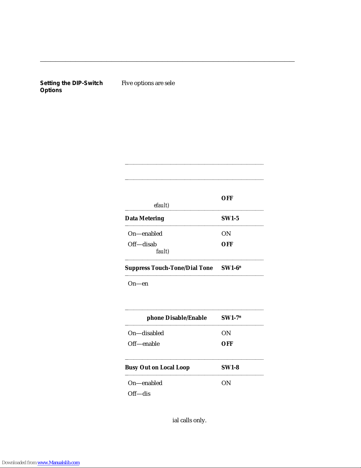
Setting the DIP-Switch
Options
Five options are selected by setting switches on an 8-position
DIP-switch. Setting these switches is described in the following
paragraph.
Note: The factory-default settings of these switches are correct
for the majority of applications. Check the default
settings shown in Table 2-1 to determine whether you
need to make any changes.
TABLE 2-1
Option DIP-Switch Settings
bbbbbbbbbbbbbbbbbbbbbbbbbbbbbbbbbbbbbbbbbbbbbbbbbb
Telephone SW1-1
bbbbbbbbbbbbbbbbbbbbbbbbbbbbbbbbbbbbbbbbbbbbbbbbbb
Without Phone ON
With Phone
(factory-default)
bbbbbbbbbbbbbbbbbbbbbbbbbbbbbbbbbbbbbbbbbbbbbbbbbb
OFF
Data Metering SW1-5
bbbbbbbbbbbbbbbbbbbbbbbbbbbbbbbbbbbbbbbbbbbbbbbbbb
On—enabled ON
Off—disabled
OFF
(factory-default)
bbbbbbbbbbbbbbbbbbbbbbbbbbbbbbbbbbbbbbbbbbbbbbbbbb
Suppress Touch-Tone/Dial Tone SW1-6*
bbbbbbbbbbbbbbbbbbbbbbbbbbbbbbbbbbbbbbbbbbbbbbbbbb
On—enabled ON
Off—disabled
OFF
(factory-default)
bbbbbbbbbbbbbbbbbbbbbbbbbbbbbbbbbbbbbbbbbbbbbbbbbb
Speakerphone Disable/Enable SW1-7*
bbbbbbbbbbbbbbbbbbbbbbbbbbbbbbbbbbbbbbbbbbbbbbbbbb
On—disabled ON
Off—enabled
OFF
(factory-default)
bbbbbbbbbbbbbbbbbbbbbbbbbbbbbbbbbbbbbbbbbbbbbbbbbb
Busy Out on Local Loop SW1-8
bbbbbbbbbbbbbbbbbbbbbbbbbbbbbbbbbbbbbbbbbbbbbbbbbb
On—enabled ON
Off—disabled
OFF
(factory-default)
* Applies to voice dial calls only.
Page 27

DEFINITY Communications System CHAPTER 2: INSTALLATION
7400B Plus Data Module
User´s Guide Page 2-13
bbbbbbbbbbbbbbbbbbbbbbbbbbbbbbbbbbbbbbbbbbbbbbbbbb
Caution: Disconnect all cables and telephone cords attached at
the rear of the unit. Failure to disconnect all cables and
cords at this point could result in permanent damage
to the 7400B Plus.
1 Remove the top access panel of the 7400B Plus as follows:
(See Figure 2-4.)
a While applying a gentle lifting pressure at the rear edge
of the access panel, insert the tip of a ball-point pen or
other suitable device into each of the two tab-lock holes
in the rear panel to release the locking tabs.
b Lift and remove the access panel.
2 If a ROM board is installed just inside the access opening of
the 7400B Plus, grasp the edges of the ROM board inside the
access opening and lift the board out of its socket.
3 Locate the 8-position DIP-switch on the main circuit board,
approximately in the center of the area exposed by the access
opening.
4 Set the appropriate positions of this DIP-switch as shown in
the Table 2-1.
5 If a ROM board was removed in step 2, reinsert the board
into its connector.
6 Replace the access panel by placing it into position and
pressing down at the rear edge to engage the locking tabs.
Page 28

CHAPTER 2: INSTALLATION DEFINITY Communications System
7400B Plus Data Module
Page 2-14 User´s Guide
bbbbbbbbbbbbbbbbbbbbbbbbbbbbbbbbbbbbbbbbbbbbbbbbbb
To access and set the DIP-switch options, refer to Figure 2-4 and
perform the following:
Artwork to be supplied
Figure 4 Accessing the DIP Switches
Page 29

DEFINITY Communications System CHAPTER 2: INSTALLATION
7400B Plus Data Module
User´s Guide Page 2-15
bbbbbbbbbbbbbbbbbbbbbbbbbbbbbbbbbbbbbbbbbbbbbbbbbb
Connecting the EIA-232-D
Cable
Connect the EIA-232-D cable between the 7400B Plus and the
terminal device as follows:
1 Insert a male connector of the EIA-232-D cable into the
connector labeled PORT on the rear panel of the 7400B Plus.
Tighten both connector retaining screws.
2 Insert the other end of the EIA-232-D cable into the
communications port connector on the terminal device.
Tighten all retaining screws.
Note: Be sure to attach any required adapter as discussed
previously in the paragraphs titled ‘‘Selecting the
EIA-232-D Cable.’’
ffffffffffffffffffffffffffffffffffffffffffff
Connecting the DCP Cord Attach the DCP type D8W telephone cord as follows:
1 Insert either end of the telephone cord into the connector on
the rear panel of the 7400B Plus labeled LINE.
2 Insert the other end of the telephone cord into the PBX wall
jack.
3 If you are using the with-phone option of the 7400B Plus
(voice and data), install the second D8W telephone cord as
follows:
a Insert one end of the second D8W cord into the jack on
your 7400 series DCP voice terminal.
b Insert the other end of the second D8W cord into the
jack on the rear panel of the 7400B Plus labeled
PHONE.
Note: An internal DIP-switch must be set correctly
for this option to work (see "Setting the DIPSwitch Options" in this chapter). Also, if your
voice terminal has data capabilities, the data
features of the voice terminal are not
supported while it is connected to the 7400B
Plus.
Page 30

CHAPTER 2: INSTALLATION DEFINITY Communications System
7400B Plus Data Module
Page 2-16 User´s Guide
bbbbbbbbbbbbbbbbbbbbbbbbbbbbbbbbbbbbbbbbbbbbbbbbbb
Connecting the Power
Supply
Connect the separate power supply unit to the 7400B Plus as
follows:
1 Insert the output connector of the power supply into the
connector on the rear panel of the 7400B Plus labeled
‘‘POWER.’’
Caution: Be sure that the side of the power supply cable
connector labeled ‘‘TOP’’ is facing upward before
inserting the connector.
2 Insert the AC connector of the power supply unit into an
appropriate AC outlet.
Note: Since the 7400B Plus does not have a power on/off
switch, the unit will power on as soon as the power
supply is connected to an active AC line.
Caution: Make certain that the AC outlet to which you
connect the power supply is unswitched (for
example, not controlled by a wall switch or light
dimmer).
Page 31

DEFINITY Communications System CHAPTER 2: INSTALLATION
7400B Plus Data Module
User´s Guide Page 2-17
bbbbbbbbbbbbbbbbbbbbbbbbbbbbbbbbbbbbbbbbbbbbbbbbbb
INITIAL SYSTEM CHECKS This section describes procedures for initially checking out your
hardware and any required software. It is assumed at this point
that your hardware and PC communications package have been
properly installed and are ready for use.
Note: PC communications software is required only if you are
using a PC as your terminal device. A dedicated data
terminal does not need PC communications software.
Power-Up Self-Test When power is first applied to the 7400B Plus, the unit performs a
self-test to determine that it is in working order. The progression
of the self-test is indicated by the sequential, left-to-right lighting
of the 10 front-panel LEDs.
When the self-test completes, the LEDs labeled POWER/TEST and
TR will remain lit and all other LED lamps will go out.
Note: The operation of the LEDs described here assumes that
the factory-default options are still in effect. Once certain
options have been changed, the operation of the LEDs
may differ from this description.
Your 7400B Plus is now installed and ready for data
communications operation.
ffffffffffffffffffffffffffffffffffffffffffff
IF YOU ARE USING A PC PC communications packages provide the capability of
configuring the 7400B Plus automatically. When using a PC
communications package with the 7400B Plus, there are two items
to note:
1 The PC communications package should be configured to
work with a Hayes Smartmodem 2400 or Hayes compatible
modem.
ffffffffffffffffffffffffffffffffffffffffffff
2 The dialing method of the PC communications package
should be set to Tone for data calls, and Pulse for voice calls.
Many PC communications packages provide the possibility of
writing script or command files. These files can then be run to
execute a sequence of commands that will configure your system,
or even provide an automatic log on procedure for a particular
remote end device. Review the documentation for your PC and
PC communications package. Once you understand the PC
communications package well enough, you will be ready to begin
using it with the 7400B Plus.
Page 32

CHAPTER 2: INSTALLATION DEFINITY Communications System
7400B Plus Data Module
Page 2-18 User´s Guide
bbbbbbbbbbbbbbbbbbbbbbbbbbbbbbbbbbbbbbbbbbbbbbbbbb
Since there is such a diversity of functionality among the many PC
communications packages available, refer to the user’s manual of
the package for specific details of its use. Chapter 4, "PC
Applications" provides guidelines for using a few of the more
popular packages with the 7400B Plus.
For more information about the ‘‘AT’’ interface and operation of
the 7400B Plus, refer to Chapter 3, "Configuration and Operation."
IF YOU ARE USING A
DEDICATED TERMINAL
ffffffffffffffffffffffffffffffffffffffffffff
When a dedicated terminal is used with a 7400B Plus, you must
control the operation of the 7400B Plus. In a way, you are acting
as a PC communication package. To do this, you must
understand the operation of the 7400B Plus. Refer to Chapter 3,
"Configuration and Operation."
Page 33

DEFINITY Communications System CHAPTER 3: CONFIGURATION AND OPERATION
7400B Plus Data Module
User´s Guide Page 3-1
bbbbbbbbbbbbbbbbbbbbbbbbbbbbbbbbbbbbbbbbbbbbbbbbbb
CHAPTER 3: CONFIGURATION AND OPERATION
This chapter describes how to change, store, and recall
configuration parameters, outlines how to create and save custom
configuration profiles, and discusses more advanced command
usage with example command lines.
This chapter also provides some basics on the 7400B Plus
operation, describes how to use a few ‘‘AT’’ commands that are
essential for most voice-data communications operations, and
then outlines a typical
on-line session.
Note: The commands for the 7400B Plus are referred to as ‘‘AT’’
commands because you must type the letters AT as the
first characters on the line for most commands.
OPERATING MODES Except when a test condition has been initiated, the 7400B Plus is
ffffffffffffffffffffffffffffffffffffffffffff
always in one of two states: command mode or data mode. When
power is first applied, the 7400B Plus initializes to command
mode.
In command mode, the 7400B Plus looks at everything you type
on your keyboard. When you type in something that the 7400B
Plus recognizes as a valid command with a valid parameter (if
required), it will execute the action requested. A valid command
with an invalid parameter will produce the ERROR result code.
An invalid command will also produce the ERROR result code,
and is ignored.
In data mode, everything you type is passed as data without
interpretation by the 7400B Plus, except the escape sequence. The
escape sequence, described in later paragraphs, provides a way of
switching the 7400B Plus back to command mode without
disconnecting a data call.
Page 34

CHAPTER 3: CONFIGURATION AND OPERATION DEFINITY Communications System
7400B Plus Data Module
Page 3-2 User´s Guide
bbbbbbbbbbbbbbbbbbbbbbbbbbbbbbbbbbbbbbbbbbbbbbbbbb
ISSUING COMMANDS The following paragraphs describe the elements of a command
line and how the 7400B Plus responds to a command line when it
is issued.
AT Command Line Prefix All commands issued to the 7400B Plus must begin with the letters
ffffffffffffffffffffffffffffffffffffffffffff
‘‘AT’’ or ‘‘at’’ with the exception of the ‘‘A/’’ command which is
discussed later. The command line prefix must be entered as
either both uppercase or both lowercase letters (that is, at and
AT will work, but aT and At will not).
The letters ‘‘AT,’’ also known as the ATtention command, alerts
the 7400B Plus to expect one or more commands to follow. The
7400B Plus examines the command line prefix to determine the
communications rate of the terminal equipment as well as its
parity setting. The 7400B Plus automatically adjusts the speed
and parity settings and uses the setting until another ‘‘AT’’
command is received, or until the 7400B Plus is powered down.
Formats supported by the 7400B Plus are shown in Table 3-1.
TABLE 3-1
CHARACTER FORMATS
bbbbbbbbbbbbbbbbbbbbbbbbbbbbbbbbbbbbbbbbbbbbbbbbbb
Data Bits Parity Stop Bits
bbbbbbbbbbbbbbbbbbbbbbbbbbbbbbbbbbbbbbbbbbbbbbbbbb
7 even or odd 1
7 mark or space 1
8 none 1
All of these parameters may be changed on the local terminal
device as needed. The 7400B Plus will adjust to match the speed
and parity of the local terminal device when it receives an ‘‘AT’’
command.
If you connect to a remote system and your screen shows a
series of nonsense characters (also referred to as ‘‘garbage’’),
chances are that you need to adjust the speed or parity on the
terminal to match the settings of the 7400B Plus.
Page 35

DEFINITY Communications System CHAPTER 3: CONFIGURATION AND OPERATION
7400B Plus Data Module
User´s Guide Page 3-3
bbbbbbbbbbbbbbbbbbbbbbbbbbbbbbbbbbbbbbbbbbbbbbbbbb
Command Buffer As you type in a command, each character is saved in a 40-
Enter
character buffer. The AT prefix, spaces, and the
end of the command line are not saved and do not add to the
character count. If you try to type more than 40 countable
characters on one line, the result code ERROR will be displayed on
your terminal screen, and the command line will be ignored.
(
fffffffbbbbbbb
)
at the
Command Line Set Up A command line begins with the AT prefix, includes one or more
commands, and finishes with a line termination character, usually
Enter
issued by pressing the
termination character is an ASCII carriage return.
If you make an error while typing a command line, you can send
the backspace character, usually issued by pressing the
Backspace
(
ffffffffffffbbbbbbbbbbbb
as soon as you enter the AT prefix, the 7400B Plus immediately
reads it and sets up for a command to follow. Hence, you cannot
delete the AT prefix once it is typed. The factory-default
backspace character is an ASCII backspace.
Once you complete a command line by pressing
7400B Plus will try to interpret all characters on the command line
as valid commands. If the 7400B Plus finds a character that is not
a valid command, it will ignore the erroneous character and any
remaining characters on the command line.
)
key, as often as needed to delete the error. However,
(
fffffffbbbbbbb
)
key. The factory-default line
Enter
(
fffffffbbbbbbb
)
, the
ffffffffffffffffffffffffffffffffffffffffffff
ffffffffffffffffffffffffffffffffffffffffffff
Command
Acknowledgement
Commands are acted upon immediately and are acknowledged by
a result code. Most commands are acknowledged by OK. This
assumes that the result codes are configured in the verbose form
(command V1 is in effect), and are enabled (Q0 in effect).
Another option for configuring result codes is the short or
numeric form. These result codes are set by the V0 command
which would produce a 0 (zero) instead of the message OK. A
final option for result codes is to configure them for visible
acknowledgement (Q1). Refer to Appendix A, "AT Command Set"
for descriptions of the V and Q commands.
Page 36

CHAPTER 3: CONFIGURATION AND OPERATION DEFINITY Communications System
7400B Plus Data Module
Page 3-4 User´s Guide
bbbbbbbbbbbbbbbbbbbbbbbbbbbbbbbbbbbbbbbbbbbbbbbbbb
Several other result codes may appear on your terminal screen
while the 7400B Plus is completing a call. The option selected by
the X command controls which of these result codes may appear
on the screen of your terminal (the X command is described in
Appendix A). All result codes that may be returned by the 7400B
Plus are shown in Table 3-2 and in Appendix E, "Quick-Reference
Summaries."
TABLE 3-2
bbbbbbbbbbbbbbbbbbbbbbbbbbbbbbbbbbbbbbbbbbbbbbbbbbbbbbbbbbbbbbbbbbbbbbbbbbbbbbbbbbbbbbbbb
Verbose Form Numeric Description
bbbbbbbbbbbbbbbbbbbbbbbbbbbbbbbbbbbbbbbbbbbbbbbbbbbbbbbbbbbbbbbbbbbbbbbbbbbbbbbbbbbbbbbbb
OK 0 Command accepted
CONNECT 1 Connection made at 300 bps
Result Codes
Note: If command X0 is in effect, CONNECT
means connection made at whatever
speed both ends of the call agreed upon.
RING 2 Ring signal detected
NO CARRIER 3 Carrier signal not detected or lost
ERROR 4 Error in command line
CONNECT 1200 5 Connection made at 1200 bps
BUSY 7 Busy signal detected
CONNECT 2400 10 Connection made at 2400 bps
CONNECT 4800 11 Connection made at 4800 bps
CONNECT 9600 12 Connection made at 9600 bps
CONNECT 19200 14 Connection made at 19200 bps
ffffffffffffffffffffffffffffffffffffffffffff
Repeating a Command As mentioned earlier, the command buffer contains the last
completed command line. If you wish to repeat the previous
command line without retyping it, type A/ without the AT
Enter
command prefix and without pressing
most useful when you have typed a command line to have the
7400B Plus dial a number, and the returns the result code BUSY.
(
fffffffbbbbbbb
)
. This command is
Page 37

DEFINITY Communications System CHAPTER 3: CONFIGURATION AND OPERATION
7400B Plus Data Module
User´s Guide Page 3-5
bbbbbbbbbbbbbbbbbbbbbbbbbbbbbbbbbbbbbbbbbbbbbbbbbb
Use the A/ command to redial the number as often as you wish.
Page 38

CHAPTER 3: CONFIGURATION AND OPERATION DEFINITY Communications System
7400B Plus Data Module
Page 3-6 User´s Guide
bbbbbbbbbbbbbbbbbbbbbbbbbbbbbbbbbbbbbbbbbbbbbbbbbb
Sample Command Lines This section presents a few sample AT command lines with
explanations of the results they will produce.
EXAMPLE 1: Checking if your terminal is communicating with
the 7400B Plus.
ENTER
(
AT
fffffffffbbbbbbbbb
Note: Remember, the two characters of the ‘‘AT’’ command
prefix must be typed as either both uppercase or both
lowercase. That is, you can type either at or AT, but At
or aT will not work.
If everything is operating properly, the command should appear
on the screen as you type it, and the 7400B Plus should respond
with OK.
EXAMPLE 2: Using a time saver.
A/
)
The A/ command tells the 7400B Plus to repeat the last command
line exactly. If you had issued the command to dial a number and
the 7400B Plus returned the message BUSY, you could type the
A/ command to try the number again.
Note: The A/ command must be the only command on the
command line, and you do not press
(
fffffffbbbbbbb
)
to
Enter
complete the line.
EXAMPLE 3: Changing data options.
at e1 &d2 s0=5
(
fffffffbbbbbbb
)
Enter
This command line is a command sequence that sets up the 7400B
Plus to automatically answer incoming calls. The commands set
the following parameters:
d
at is the required command prefix,
d
e1 causes characters entered from the keyboard to be
echoed to the screen while in command mode
d
&d2 causes the 7400B Plus to hang up the call when the
local terminal turns off DTR
d
s0=5 causes the 7400B Plus to enter automatic answer
mode and answer incoming calls on the fifth ring.
Page 39

DEFINITY Communications System CHAPTER 3: CONFIGURATION AND OPERATION
7400B Plus Data Module
User´s Guide Page 3-7
bbbbbbbbbbbbbbbbbbbbbbbbbbbbbbbbbbbbbbbbbbbbbbbbbb
CONFIGURATION
PARAMETERS
Parameter Storage and
Retrieval
Values for configuration parameters are selected by using ‘‘AT’’
commands. For a description of ‘‘AT’’ commands used by the
7400B Plus, refer to Appendix A, "AT Command Set."
ffffffffffffffffffffffffffffffffffffffffffff
Configuration parameter values include the option values selected
by ‘‘AT’’ commands that require option values, and the values
stored in the S-registers. A set of configuration parameter values
is called a profile. The 7400B Plus has four configuration profiles
at any given time, one active, two stored, and one that
permanently contains the factory-default values.
Unsaved changes to configuration parameters remain in effect
until they are changed again, or until the 7400B Plus is
disconnected from the AC power source. Before making or
storing any changes, or to check changes that you have made, you
can issue an ‘‘AT’’ command to view the values that are currently
in the active profile and the two stored profiles.
The active profile contains the parameter values that are currently
in effect. All parameter values can be changed, and most changes
can be stored to one of the two profile storage locations by issuing
an ‘‘AT’’ command. Another ‘‘AT’’ command recalls values from
one of the two stored profiles into the active profile.
Factory-default parameter values are a selection of values that are
appropriate for a wide number of applications. These values are
stored permanently in ROM and you can issue an ‘‘AT’’ command
to recall them into the active profile at any time.
Page 40

CHAPTER 3: CONFIGURATION AND OPERATION DEFINITY Communications System
7400B Plus Data Module
Page 3-8 User´s Guide
bbbbbbbbbbbbbbbbbbbbbbbbbbbbbbbbbbbbbbbbbbbbbbbbbb
Commands to view, store, and recall configuration parameters are
summarized in Table 3-3. The commands discussed in this section
are described in greater detail in Appendix A, "AT Command Set."
To determine whether a configuration parameter that affects a
particular
S-register can be stored in memory, refer to Appendix C, "SRegisters."
TABLE 3-3
bbbbbbbbbbbbbbbbbbbbbbbbbbbbbbbbbbbbbbbbbbbbbbbbbbbbbbbbbbbbbbbbbbbbbbbbbbbbbbbbbbbbbb
Command Line: Action:
bbbbbbbbbbbbbbbbbbbbbbbbbbbbbbbbbbbbbbbbbbbbbbbbbbbbbbbbbbbbbbbbbbbbbbbbbbbbbbbbbbbbbb
Enter
(
at&v
fffffffbbbbbbb
Commands to Store, Recall and View Configuration Parameters
)
Display current ‘‘AT’’ command settings and S-register
values in the active profile and the two stored profiles
(also displays the four stored telephone numbers, which
are described in a section of this chapter titled ‘‘Number
Storage’’).
at&wn
atzn
at&yn
at&f
Enter
(
fffffffbbbbbbb
Enter
(
fffffffbbbbbbb
Enter
(
fffffffbbbbbbb
Enter
(
fffffffbbbbbbb
)
Store the configuration parameters in the active profile
to one of the two storage locations, where n represents
the desired location and may be 0 or 1.
)
Immediately reset the 7400B Plus and recall one of the
two stored configuration profiles into active status,
where n represents the desired profile and may be 0 or 1.
)
Recall one of the two stored configuration profiles into
active status when the 7400B Plus is powered on, where
n represents the desired profile and may be 0 or 1.
)
Recall the factory-default configuration settings into the
active profile.
Page 41

DEFINITY Communications System CHAPTER 3: CONFIGURATION AND OPERATION
7400B Plus Data Module
User´s Guide Page 3-9
bbbbbbbbbbbbbbbbbbbbbbbbbbbbbbbbbbbbbbbbbbbbbbbbbb
DATA OPERATION This section provides information on how to use the 7400B Plus
for data calls.
From Data Mode to
Command Mode and Back
An escape sequence, +++, can be typed at any time during a data call
to return temporarily to command mode. Your call does not
disconnect, but data is not exchanged. Once you have ‘‘escaped’’
to command mode, the 7400B Plus returns OK to acknowledge
that it has entered command mode (see section titled ‘‘Command
Acknowledgement’’).
At this point, you can issue commands to the 7400B Plus. As long
as the data call has not been disconnected, you can use the ‘‘ato’’
command to return to data mode.
One other condition will cause the 7400B Plus to switch from data
mode to command mode. If the PBX senses that the remote
device has disconnected, it will disconnect the call to the 7400B
Plus. The 7400B Plus will turn off the CD, OH, and DATA LEDs,
display a result code message on your terminal screen (such as
NO CARRIER), and then return to command mode.
The escape sequence and all other commands discussed in this
section are explained in Appendix A, "AT Commands."
ffffffffffffffffffffffffffffffffffffffffffff
Dialing a Data Call The dial command is issued to the 7400B Plus in the form
atdtnnn...n, where d is the dial command, t is the dial modifier
(see "Appendix B" for more information on dial modifiers), and
nnn...n represents the number you wish to dial. The command line
can hold up to 40 characters, so you can usually precede the d
with other commands on the same line.
ffffffffffffffffffffffffffffffffffffffffffff
The following is an example:
Enter
atdt74768
In the example, the command will cause the 7400B Plus to go off
hook, dial the number, and then wait the period of time specified
in S-register S7 for the call to be completed.
If the call can not be completed, the 7400B Plus may disconnect
and send the result code NO CARRIER or BUSY to your display
screen. When a call is successfully completed, the 7400B Plus will
send the result code CONNECT nnnn to your screen, where nnnn
(
fffffffbbbbbbb
)
Page 42

CHAPTER 3: CONFIGURATION AND OPERATION DEFINITY Communications System
7400B Plus Data Module
Page 3-10 User´s Guide
bbbbbbbbbbbbbbbbbbbbbbbbbbbbbbbbbbbbbbbbbbbbbbbbbb
represents the speed of the 7400B Plus, (for example, 1200).
Page 43

DEFINITY Communications System CHAPTER 3: CONFIGURATION AND OPERATION
7400B Plus Data Module
User´s Guide Page 3-11
bbbbbbbbbbbbbbbbbbbbbbbbbbbbbbbbbbbbbbbbbbbbbbbbbb
Storing a Telephone
Number
The 7400B Plus is capable of storing up to four telephone
numbers, each of which can contain up to 25 characters. Numbers
stored in this way remain available indefinitely, even after the
7400B Plus has been powered off and then on again.
Table 3-4 describes the command lines used to store a telephone
number, delete a number from storage, and dial a stored number.
Note: Digits 0 through 9 and all letters ‘‘a’’ through ‘‘z’’ and
‘‘A’’ through ‘‘Z’’ may be part of the stored ‘‘number.’’
Spaces and hyphens (-) may be used in the number when
typing the command line. Spaces are not stored and do
not add to the total count of characters in the stored
number, but all other ASCII characters are stored and
counted. Any ASCII character may be used, as long as it
is acceptable to the PBX. A semi-colon (;) character
cannot be stored because it is used to delimit the end of
the string being stored so that additional commands can
be entered on the same command line.
Page 44

CHAPTER 3: CONFIGURATION AND OPERATION DEFINITY Communications System
7400B Plus Data Module
Page 3-12 User´s Guide
bbbbbbbbbbbbbbbbbbbbbbbbbbbbbbbbbbbbbbbbbbbbbbbbbb
TABLE 3-4
bbbbbbbbbbbbbbbbbbbbbbbbbbbbbbbbbbbbbbbbbbbbbbbbbbbbbbbbbbbbbbbbbbbbbbbbbbbbbbbbbbbbbb
Command line: Action:
bbbbbbbbbbbbbbbbbbbbbbbbbbbbbbbbbbbbbbbbbbbbbbbbbbbbbbbbbbbbbbbbbbbbbbbbbbbbbbbbbbbbbb
Enter
(
fffffffbbbbbbb
(
fffffffbbbbbbb
)
at&zm=nnn...n
at&zm=
Commands for Using Stored Telephone Numbers
Enter
)
Store number nnn...n in location m, which is one of four
locations designated by the numbers 0 through 3. For
example:
at&z2=918006245123
stores the number 918006245123 in number storage
location 2.
Delete any number stored in location m, which is one of
four locations designated by the numbers 0 through 3.
For example:
Enter
at&z2=
(
fffffffbbbbbbb
)
deletes any number that may have been stored in
number storage location 2.
Enter
(
fffffffbbbbbbb
)
atds=m
(
fffffffbbbbbbb
)
Dial the number stored in location m, which is one of
Enter
four locations designated by the numbers 0 through 3.
For example:
Enter
atds=2
(
fffffffbbbbbbb
)
causes the 7400B Plus to dial the number stored in
location 2.
ffffffffffffffffffffffffffffffffffffffffffff
Automatic Answering The 7400B Plus can be set up to answer incoming data calls
automatically. To initialize this option, type the command line:
Enter
ats0=nnn
(
fffffffbbbbbbb
where nnn is a decimal number in the range of 1 through 255,
representing the number of rings to wait before answering. If nnn
is 0 (the factory-default setting), the automatic answer feature is
turned off. The red LED on the front of the 7400B Plus labeled
‘‘AA’’ lights when the automatic feature is turned on.
)
Page 45

DEFINITY Communications System CHAPTER 3: CONFIGURATION AND OPERATION
7400B Plus Data Module
User´s Guide Page 3-13
bbbbbbbbbbbbbbbbbbbbbbbbbbbbbbbbbbbbbbbbbbbbbbbbbb
Remote Site Use The 7400B Plus can be used at a remote site as a dedicated service
device to answer incoming data calls, send data to a remote end
device, and then hang up. For example, you may wish to provide
access to a printer from a remote site.
The following is a typical command line you might use for setting
up this operation (spaces are used here for readability, but are not
required):
Enter
AT &F &C1 &D2 E0 Q1 S0=1 &W0 &Y0
(
fffffffbbbbbbb
Following the AT prefix, the commands in the example produce
the following results:
d
&F resets the options to the factory defaults.
d
&C1 sets the Data Carrier Detect (DCD) circuit of the 7400B
Plus to operate according to the EIA standard.
d
&D2 sets the 7400B Plus to go on hook when an on-to-off
transition is detected on the Data Terminal Ready (DTR) input,
disconnecting the call
)
d
E0 turns off the echo.
d
Q1 turns off the result codes that would be the normal
responses of the 7400B Plus to commands that it receives. (For
example, the ‘‘CONNECT’’ message which is displayed when
answering a call would interfere with the printer.)
d
S0=1 turns on the automatic answer feature and causes the
7400B Plus to answer an incoming data call on the first ring.
d
&W0 causes the current configuration to be stored in data
profile storage location 0.
d
&Y0 selects the configuration stored in data profile storage
location 0 to become the current configuration each time the
7400B Plus is powered on
Refer to Appendix A, "AT Command Set," for a complete
description of each command used in this section.
Page 46

CHAPTER 3: CONFIGURATION AND OPERATION DEFINITY Communications System
7400B Plus Data Module
Page 3-14 User´s Guide
bbbbbbbbbbbbbbbbbbbbbbbbbbbbbbbbbbbbbbbbbbbbbbbbbb
Reset and Configuration
Recall
Two commands are available for recovering from various data
communications problems. You can reset the 7400B Plus and
recall one of two stored profiles as the current configuration. The
form for this command is as follows:
atzn
(
fffffffbbbbbbb
)
Enter
where n is the number 0 or 1, representing the configuration
profile to be recalled.
A second command allows you to recall the factory-default
configuration if, for instance, you loose track of changes you have
made and need to start over. The form for this command is as
follows:
at&f
(
fffffffbbbbbbb
)
Enter
ffffffffffffffffffffffffffffffffffffffffffff
Sample Command Lines This section presents a few sample AT command lines for data
calls, along with explanations of the results they will produce.
EXAMPLE 1: Dialing a data call.
Enter
AT D T 18006245123
CONNECT 2400
In the first line of this example,
(
fffffffbbbbbbb
)
d
AT is the required command prefix,
d
D is the dial command,
d
T is the dial modifier for a data call (not required),
d
and the remainder of the line is the telephone number.
Note: The spaces between the commands and the telephone
number are included only for readability and are not
required. You may also insert hyphens (-) anywhere in
the telephone number for increased readability.
In the second line of this example, the 7400B Plus returns a
response indicating that a connection with the remote end device
has been successfully completed at 2400 bps.
Page 47

DEFINITY Communications System CHAPTER 3: CONFIGURATION AND OPERATION
7400B Plus Data Module
User´s Guide Page 3-15
bbbbbbbbbbbbbbbbbbbbbbbbbbbbbbbbbbbbbbbbbbbbbbbbbb
EXAMPLE 2: Dialing a data call outside your PBX domain with a
few other options thrown in.
Enter
at &f d 9 1 800 624-5123
(
fffffffbbbbbbb
BUSY
In the first line of this example,
d
at is the required command prefix,
d
&f tells the 7400B Plus to restore the factory-default
configuration parameters,
d
d is the dial command,
d
9 represents the access code required to dial a number
outside your PBX domain,
d
and the remainder of the line is the telephone number.
In the second line of this example, the 7400B Plus indicates that it
detected a busy signal, and the call is automatically disconnected.
)
Page 48

CHAPTER 3: CONFIGURATION AND OPERATION DEFINITY Communications System
7400B Plus Data Module
Page 3-16 User´s Guide
bbbbbbbbbbbbbbbbbbbbbbbbbbbbbbbbbbbbbbbbbbbbbbbbbb
A Sample On-Line Session This section outlines how to perform a simple on-line session
using the ‘‘AT’’ commands described in this chapter. For more
information about all ‘‘AT’’ commands, see Chapter 3,
"Configuration and Operation" and Appendix A, "AT Command
Set."
ffffffffffffffffffffffffffffffffffffffffffff
Starting the Session
The following is a sample data call to a fictitious bulletin board
service. If you know the number of a ‘‘real’’ bulletin board
service, you might try an actual log on by using that number and
following the suggestions in this session.
Enter
at d 9-555-7575
CONNECT 1200
The D command is used to dial the number of the bulletin board.
Since the connection was made successfully, the 7400B Plus
responded with a message that says the remote end connected
and the data speed to be used is 1200 bps.
(
fffffffbbbbbbb
)
The remote end may do nothing until you press a particular key a
Enter
few times, usually
communications application programs, this sometimes required
input lets the remote end determine whether you have connected
with the correct communications parameters in effect.
(
fffffffbbbbbbb
)
. Typical of many data
ffffffffffffffffffffffffffffffffffffffffffff
Possible Display Problems
If the response from the remote end is unintelligible ‘‘garbage,’’
chances are that the speed or parity bit selection is incorrect. In
this case, assuming that your terminal device allows, the
parameters may be corrected without disconnecting the call.
Otherwise, you must disconnect, correct the parameters, and then
try the call again.
Another possible problem is that the remote end response
contains normal words mixed in with strange characters, many of
which are left brackets ([). This usually indicates that the remote
device is sending ANSI display control sequences, and your
terminal does not recognize them (ANSI stands for American
National Standards Institute).
On a PC, this can generally be remedied by first disconnecting the
call, editing the PC’s CONFIG.SYS file to include the line
DEVICE=ANSI.SYS
rebooting the PC, and then trying the call again. (For a log off
procedure, see the alternative method under ‘‘Disconnecting a
Data Call,’’ below.)
Page 49

DEFINITY Communications System CHAPTER 3: CONFIGURATION AND OPERATION
7400B Plus Data Module
User´s Guide Page 3-17
bbbbbbbbbbbbbbbbbbbbbbbbbbbbbbbbbbbbbbbbbbbbbbbbbb
Note: If the terminal device is not a PC, or the suggested
remedy does not seem to solve the problem, you will need
to consult the documentation for your dedicated terminal,
or for your PC and any software involved.
ffffffffffffffffffffffffffffffffffffffffffff
Disconnecting a Data Call
Most remote systems will have a command or menu selection for
logging off. When you select the appropriate means, the remote
system will disconnect or hang up. The PBX will disconnect the
call and, after a moment, the 7400B Plus will send the following
message to your display:
NO CARRIER
Alternatively, you can use the following disconnect procedure:
Selection: +++
OK
The prompt Selection: is simply a representation of how the remote
system might ask you for your next command or menu selection.
Type the escape sequence (default is +++) but do not press
Enter
(
fffffffbbbbbbb
pause again after typing +++.) When the 7400B Plus responds
with OK, type the command line:
The PBX will disconnect from the remote end device, and the
7400B Plus will send the OK message to the terminal display.
)
. (Pause before typing +++, type +++ quickly, and then
Enter
ath
(
fffffffbbbbbbb
)
Page 50

CHAPTER 3: CONFIGURATION AND OPERATION DEFINITY Communications System
7400B Plus Data Module
Page 3-18 User´s Guide
bbbbbbbbbbbbbbbbbbbbbbbbbbbbbbbbbbbbbbbbbbbbbbbbbb
VOICE OPERATIONS This section provides information on how to use the 7400B Plus
for voice dialing.
Using the 7400B Plus for
Voice Dialing
The 7400B Plus is equipped with a voice dial feature which allows
you to place voice telephone calls from the attached terminal
device. To place a voice call, just tell the 7400B Plus to use pulse
dialing by including the ‘‘P’’ dial modifier. (For data calls, tell it to
use tone dialing by including the ‘‘T’’ dial modifier.) If you fail to
specify the type of dialing to be used for a call, a data call will be
made.
If you have a speakerphone, the 7400B Plus will normally turn it
on when a voice call is being dialed. You may option the 7400B
Plus to inhibit the speakerphone or delay activating it until after
dialing is complete by setting the appropriate DIP switches. For
more information on DIP switches, see Chapter 2, "Installation."
If your telephone does not have a speakerphone, you may lift the
handset at any time.
Voice calls can be originated from the PC, but you must use the
telephone to hang-up a call.
ffffffffffffffffffffffffffffffffffffffffffff
Dialing Instructions When a voice call is made using the PC, the telephone number
should be given to the 7400B Plus in a single ‘‘AT’’ dial command
as indicated in the example below.
ffffffffffffffffffffffffffffffffffffffffffff
ATD P 9,1 (908) 555-1212
The ‘‘P’’ dial modifier must be included to tell the 7400B Plus that
the call is a voice call. If an attempt to dial a voice call is made
using more than one dial command on a command line, the first
dial command will be accepted and the second dial command
may be discarded. After dialing the call, the 7400B Plus
automatically returns to the command mode.
A second voice call can be made from your PC by manually
placing the first call on HOLD, and then entering a dial command
for the second call. Any attempt to dial a second voice call while
the first call is being dialed will be ignored.
Note: On DEFINITY Communications Generic 1, System 75,
if you are in directory mode on the telephone, the
procedures are ignored.
On DEFINITY Communications Generic 2, System 85,
after you have manually placed the first call on HOLD,
you must select a second call appearance before entering
a dial command for the second call.
Page 51

DEFINITY Communications System CHAPTER 3: CONFIGURATION AND OPERATION
7400B Plus Data Module
User´s Guide Page 3-19
bbbbbbbbbbbbbbbbbbbbbbbbbbbbbbbbbbbbbbbbbbbbbbbbbb
Dialing Delay To ensure that dialing does not begin before dial tone is received,
dialing a voice call will be delayed by the time stored in the S6
register (Wait Time Before Blind Dialing register) and can be set to
a maximum value of 255 seconds. The factory setting of 2 seconds
for S6 is adequate for most calls and should not be changed.
Dialing Pause A pause for second dial tone is normally required for calls outside
the PBX. This can be provided by including a comma between the
outside line prefix (for example, 9) and the first digit of the
telephone number to be dialed. The comma instructs the 7400B
Plus, after dialing the prefix number, to pause a fixed time before
dialing the first digit of the telephone number. The pause time is
stored in the S8 register (Duration of Delay For Comma Dial
Modifier) and can be set for any value up to a maximum of 255
seconds. The factory setting of 2 seconds is adequate for most
applications and it should not be changed. If added delay is
required, additional commas can be added to the number.
ffffffffffffffffffffffffffffffffffffffffffff
Sample Command Line This section presents a few sample AT command lines for voice
dialing, along with explanations of the results they will produce.
EXAMPLE 1: Dialing a voice call.
Enter
ffffffffffffffffffffffffffffffffffffffffffff
atd p 9,1 9085551212
OK
In the first line of this example,
d
at is the required command prefix,
d
d is the dial command,
(
fffffffbbbbbbb
)
d
p is the dial modifier required to initiate a voice call,
d
9 represents the access code required to dial a number
outside your PBX domain,
d
, (comma) is the dial modifier pause required for a second
dial tone,
d
1 represents the code required to dial a number outside
your area code,
d
and the remainder of the line is the telephone number.
Page 52

CHAPTER 3: CONFIGURATION AND OPERATION DEFINITY Communications System
7400B Plus Data Module
Page 3-20 User´s Guide
bbbbbbbbbbbbbbbbbbbbbbbbbbbbbbbbbbbbbbbbbbbbbbbbbb
EXAMPLE 2: Using the 7400B Plus as a touch tone generator.
Enter
atd p 8000,,3452#, 999#
d
at is the required command prefix,
d
d is the dial command,
d
p is the dial modifier required to initiate a voice call,
d
8000 is the internal number for accessing AUDIX, the voice
(
fffffffbbbbbbb
mail system,
d
,, (two commas) introduce a double delay while the call is
being established,
d
3452# is the extension for the messages you want to receive,
d
999# is the password or the above extension.
At this point you are in your voice mail system ready to send,
receive, etc. messages.
)
EXAMPLE 3: Using the 7400B Plus to enter multiple commands.
at dt 9,1 800 624-5123; dp 555-1212; o
Enter
(
fffffffbbbbbbb
d
at is the required command prefix,
d
d is the dial command,
d
t is the dial modifier required to initiate a data call,
d
9 represents the access code required to dial a number outside
)
your PBX domain,
d
, (comma) is the dial modifier pause required for a second dial
tone,
d
1 represents the code required to dial a number outside your
area code,
d
800 624-5123 is the remainder of the data call,
d
; (semi-colon) returns you to the command mode,
d
d is the dial command,
d
p is the dial modifier required to initiate a voice call,
d
555-1212 is the remainder of the voice call,
d
; (semi-colon) returns you to the command mode, and
d
o sends you back to the data connection.
Page 53

DEFINITY Communications System CHAPTER 4: PC APPLICATIONS
7400B Plus Data Module
User´s Guide Page 4-1
bbbbbbbbbbbbbbbbbbbbbbbbbbbbbbbbbbbbbbbbbbbbbbbbbb
CHAPTER 4: PC APPLICATIONS
This chapter provides information that describes how to configure
some popular data and voice PC communications packages for
use with the 7400B Plus.
Some of the functions and features mentioned in this chapter may
not be available to you depending on the version of the software
that you are using.
DATA CALL NOTES The 7400B Plus has been tested with a variety of communications
packages for use with DOS and Macintosh PCs.
To dial a data call, the modem configuration must be set to TONE
(T) dialing. If given a choice, set the modem type to Hayes 2400
Smartmodem or just Hayes.
These software packages were tested with the 7400B Plus at a rate
of 2400. Check with your System 75/85 administrator to
determine the appropriate baud rate to use on your system.
When you are placing a call, if the Carrier Detect lamp is on and
your computer cannot communicate with the far end, check to
make sure that you have set the appropriate communication
parameters for that service.
ffffffffffffffffffffffffffffffffffffffffffff
VOICE DIALING NOTES The 7400B Plus voice dialing feature has been tested with the
following PC Communication Packages:
d
Hot Line V2.2
d
SideKick V1.5 and SideKick Plus V1.0
d
PC Tools V6
For PC communication packages to dial voice calls, the modem
configuration must be set to PULSE (P) dialing (even though the
7400B Plus will use Touch-Tone). If given a choice, set modem
type to Hayes 2400 Smartmodem or just Hayes.
ffffffffffffffffffffffffffffffffffffffffffff
Note: While the 7400B Plus supports simultaneous voice and
data, the above packages support alternate voice/data
DIALING only. It is possible to dial a voice call with a
data call on hold, but the above voice dialing packages
interfere with data operation, by remapping the COM
port or by hanging up the data call.
You can dial a data call while on a voice call. In all cases, the
linked telephone will work.
Page 54

CHAPTER 4: PC APPLICATIONS DEFINITY Communications System
7400B Plus Data Module
Page 4-2 User´s Guide
bbbbbbbbbbbbbbbbbbbbbbbbbbbbbbbbbbbbbbbbbbbbbbbbbb
PC COMMUNICATIONS
PACKAGES
The PC communications package versions documented in this
manual are listed in the table below.
bbbbbbbbbbbbbbbbbbbbbbbbbbbbbbbbbbbbbbbbbbbbbbbbbbb
c
c
bbbbbbbbbbbbbbbbbbbbbbbbbbbbbbbbbbbbbbbbbbbbbbbbbbb
c
c
c
bbbbbbbbbbbbbbbbbbbbbbbbbbbbbbbbbbbbbbbbbbbbbbbbbbb
c
bbbbbbbbbbbbbbbbbbbbbbbbbbbbbbbbbbbbbbbbbbbbbbbbbbb
c
bbbbbbbbbbbbbbbbbbbbbbbbbbbbbbbbbbbbbbbbbbbbbbbbbbb
c
c
bbbbbbbbbbbbbbbbbbbbbbbbbbbbbbbbbbbbbbbbbbbbbbbbbbb
c
bbbbbbbbbbbbbbbbbbbbbbbbbbbbbbbbbbbbbbbbbbbbbbbbbbb
c
c
bbbbbbbbbbbbbbbbbbbbbbbbbbbbbbbbbbbbbbbbbbbbbbbbbbb
c
bbbbbbbbbbbbbbbbbbbbbbbbbbbbbbbbbbbbbbbbbbbbbbbbbbb
c
c
bbbbbbbbbbbbbbbbbbbbbbbbbbbbbbbbbbbbbbbbbbbbbbbbbbb
c
bbbbbbbbbbbbbbbbbbbbbbbbbbbbbbbbbbbbbbbbbbbbbbbbbbb
c
bbbbbbbbbbbbbbbbbbbbbbbbbbbbbbbbbbbbbbbbbbbbbbbbbbb
c
c
bbbbbbbbbbbbbbbbbbbbbbbbbbbbbbbbbbbbbbbbbbbbbbbbbbb
c
bbbbbbbbbbbbbbbbbbbbbbbbbbbbbbbbbbbbbbbbbbbbbbbbbbb
c
c
bbbbbbbbbbbbbbbbbbbbbbbbbbbbbbbbbbbbbbbbbbbbbbbbbbb
c
bbbbbbbbbbbbbbbbbbbbbbbbbbbbbbbbbbbbbbbbbbbbbbbbbbb
c
bbbbbbbbbbbbbbbbbbbbbbbbbbbbbbbbbbbbbbbbbbbbbbbbbbb
c
c
bbbbbbbbbbbbbbbbbbbbbbbbbbbbbbbbbbbbbbbbbbbbbbbbbbb
c
bbbbbbbbbbbbbbbbbbbbbbbbbbbbbbbbbbbbbbbbbbbbbbbbbbb
c
c
bbbbbbbbbbbbbbbbbbbbbbbbbbbbbbbbbbbbbbbbbbbbbbbbbbbc
PC Communications Packages
c
Software Package Version
c
c
CARBON COPY Plus 5.1
Crosstalk XVI 3.71
Crosstalk Mk.4 1.1
Hot Line * 2.2
HyperACCESS 3.32
MicroPhone ** 1.5
PC Tools Deluxe * 6
Procomm Plus 1.1B
Relay Gold 3.0
SideKick Plus * 1.0
Smartcom II 2.2
Smartcom II 3.1
Smartcom II ** 3.1
Smartcom III 1.1
Smarterm 240 3.0a
Terra Nova 1.1.1
White Knight ** 11
c
c
c
c
c
c
c
c
c
c
c
c
c
c
c
c
c
c
c
c
c
c
c
c
c
c
c
c
c
c
c
c
c
c
c
c
c
c
c
c
c
c
c
c
c
c
c
c
c
c
c
c
c
c
aaaaaaaaaaaaaaaaaaa
* Voice dial PC communications packages
** Macintosh PC communications packages
** A cable is necessary to convert from an 8 or 9 pin RS-232-C connector on the Macintosh to the 25 pin RS-232-C
connector on the 7400B Plus.
Page 55

DEFINITY Communications System CHAPTER 4: PC APPLICATIONS
7400B Plus Data Module
User´s Guide Page 4-3
bbbbbbbbbbbbbbbbbbbbbbbbbbbbbbbbbbbbbbbbbbbbbbbbbb
CARBON COPY PLUS - V
5.1
CARBON COPY Plus is a data communications software package
produced by MicroCom.
ffffffffffffffffffffffffffffffffffffffffffff
7400B Plus The 7400B Plus is configured in the CARBON COPY Plus
installation procedure.
ffffffffffffffffffffffffffffffffffffffffffff
Installation Procedure 1 Change to the CARBON COPY Plus directory.
2 At the DOS prompt, type in "ccinstall."
bbbbbbbbbbbbbbbbbbbbbbbbbbbbbbbbbbb
c
435.if 0>0 .nr 38 0/1
c
c
c
c
c
c
c
c
c
c
c
c
c
========CARBON COPY Plus System Parameters (5.1)=======
c
c
c
c
GENERAL PARAMETERS EXIT OPTIONS
c
c
c
c
c
c
A -- Comm Port Address.....COM1 Q -- Quit, changes not saved
c
c
B -- Baud Rate.............2400 X -- eXit, changes saved
c
c
c
c
C -- Modem Type............Hayes V-Series
c
c
D -- Keyboard handling.....USA Keyboard
c
c
c
c
E -- Display TYpe..........Color
c
c
F -- Menu Colors...........White on Blue
c
c
c
c
G -- Working Directory.....C:
c
c
H -- Menu Level Options....Advanced
c
c
c
c
c
c
c
c
c
c
c
c
1 -- CC Optional Configuration Parameters
c
c
c
c
2 -- CCHELP Optional Configuration Parameters
c
c
c -- Call Table
c
c
c
c
4 -- Password Table
c
c
c
c
c
c
c
c
c
c
c
c
c
c
c
c
bbbbbbbbbbbbbbbbbbbbbbbbbbbbbbbbbbbbbbbbbbbbbbbbbbbbbbbbbbbbbbbbbbbbbbbbbbbbbbbbb
c
c
bbbbbbbbbbbbbbbbbbbbbbbbbbbbbbbbbbbbbbbbbbbbbbbbbbbbbbbbbbbbbbbbbbbbbbbbbbbbbbbbbb
MENU LIST
Type letter for selection:
c
c
c
c
c
c
c
c
c
c
c
c
c
c
c
c
c
c
c
c
c
c
c
c
c
c
c
c
c
c
c
c
c
c
c
c
c
c
c
c
c
c
c
c
c
c
c
c
c
c
c
c
c
c
c
c
c
c
c
c
c
c
c
c
c
c
c
c
c
c
c
c
c
c
c
c
c
c
c
c
c
c
c
cbbbbbbbbbbbbbbbbbbbbbbbbbbbbbbbbbbb
Figure 1 CARBON COPY Plus - System Parameters
3 Change the value of the following options by pressing the
letter listed next to it. For example, to change the "Comm
Port Address" for COM 1 press "A" until COM 1 appears.
a Set the Communication Port Address to which the
7400B Plus is connected (typically COM 1).
b Set the default Baud Rate (300, 1200, 2400,etc.).
c Depending on the version of CARBON COPY Plus you
are using, select the following for the Modem type:
d
For versions prior to 5.1, choose "Hayes
Compatible."
d
For version 5.1, choose "Hayes V" series.
Page 56

CHAPTER 4: PC APPLICATIONS DEFINITY Communications System
7400B Plus Data Module
Page 4-4 User´s Guide
bbbbbbbbbbbbbbbbbbbbbbbbbbbbbbbbbbbbbbbbbbbbbbbbbb
Setting Up a
Directory Call
Example Setup: (For example purposes, a call to ATTMAIL will be
used for the setup.)
1 Select the appropriate number for the "Call Table."
bbbbbbbbbbbbbbbbbbbbbbbbbbbbbbbbbbb
c
c
c
c
c
Use Arrow Keys, Pg Up, Pg Dn, Home & End to Position Field Pointer
c
c
c
c
c
To Edit a Field enter a character, Ins, Del or F1
c
c
c
c
c
c
c
F1 -- Edit Current Field F2 -- Insert Line
c
c
F3 -- Delete Current Line Entry F4 -- Sort Entries by Name
c
c
c
c
c
F5 -- Edit Current Line Emulation Table F6 -- Special Phone Characters
c
c
F7 -- Print Call Table F9 -- Help
c
c
c
c
c
F10 - Exit to Main Menu
bbbbbbbbbbbbbbbbbbbbbbbbbbbbbbbbbbbbbbbbbbbbbbbbbbbbbbbbbbbbbbbbbbbbbbbbbbbbbbbbbbbbbbbbbb
bbbbbbbbbbbbbbbbbbbbbbbbbbbbbbbbbbbbbbbbbbbbbbbbbbbbbbbbbbbbbbbbbbbbbbbbbbbbbbbbbbbbbbbbbb
c
c
c
c
Name Telephone Number Password(:Batch File)
c
bbbbbbbbbbbbbbbbbbbbbbbbbbbbbbbbbbbbbbbbbbbbbbbbbbbbbbbbbbbbbbbbbbbbbbbbbbbbbbbbbbbbbbbbbb
bbbbbbbbbbbbbbbbbbbbbbbbbbbbbbbbbbbbbbbbbbbbbbbbbbbbbbbbbbbbbbbbbbbbbbbbbbbbbbbbbbbbbbbbbb
c
c
c
c
ATTMAIL 9,18006245123
c
c
c
c
c
c
c
c
c
c
c
c
c
c
c
c
c
bbbbbbbbbbbbbbbbbbbbbbbbbbbbbbbbbbbbbbbbbbbbbbbbbbbbbbbbbbbbbbbbbbbbbbbbbbbbbbbbbbbbbbbbbb
c
c
bbbbbbbbbbbbbbbbbbbbbbbbbbbbbbbbbbbbbbbbbbbbbbbbbbbbbbbbbbbbbbbbbbbbbbbbbbbbbbbbbbbbbbbbbb
c
c
bbbbbbbbbbbbbbbbbbbbbbbbbbbbbbbbbbbbbbbbbbbbbbbbbbbbbbbbbbbbbbbbbbbbbbbbbbbbbbbbbbbbbbbbbb
c
c
c
c
bbbbbbbbbbbbbbbbbbbbbbbbbbbbbbbbbbbbbbbbbbbbbbbbbbbbbbbbbbbbbbbbbbbbbbbbbbbbbbbbbbbbbbbbbbb
c
c
Figure 2 CARBON COPY Plus - Call Table
2 Enter "ATTMAIL" in the name field and press < ENTER> .
===========CALL TABLE===========
FUNCTION KEYS
c
c
c
c
c
c
c
c
c
c
c
c
c
c
c
c
c
c
c
c
c
c
c
c
c
c
c
c
c
c
c
c
c
c
c
c
c
c
c
c
c
c
c
c
c
c
c
c
c
c
c
c
c
c
c
c
c
c
c
c
c
c
c
c
c
c
c
c
c
c
c
c
c
c
c
c
c
c
c
c
c
c
c
c
c
c
c
c
c
c
c
c
c
c
c
c
c
c
c
c
c
c
c
c
c
c
c
c
c
c
c
c
c
c
c
c
c
c
c
c
c
c
cbbbbbbbbbbbbbbbbbbbbbbbbbbbbbbbbbbb
3 Enter "9,18006245123" in the telephone number field and
press
< ENTER> .
4 Select "F5" for the "Edit Current Line Emulation Table."
Page 57

DEFINITY Communications System CHAPTER 4: PC APPLICATIONS
7400B Plus Data Module
User´s Guide Page 4-5
bbbbbbbbbbbbbbbbbbbbbbbbbbbbbbbbbbbbbbbbbbbbbbbbbb
bbbbbbbbbbbbbbbbbbbbbbbbbbbbbbbbbbb
c
c
c
c
c
c
c
c
c
c
c
c
Figure 3 CARBON COPY Plus - Terminal Emulator Configuration
5 Change the value of the following options in the figure
6 Set the "Terminal Emulator" value to the type of terminal
============TERMINAL EMULATOR CONFIGURATION============
bbbbbbbbbbbbbbbbbbbbbbbbbbbbbbbbbbbbbbbbbbbbbbbbbbbbbbbbbbbbbbbbbbbbbbbbbbbbbbbbbbbbbbbbbbbbbbb
bbbbbbbbbbbbbbbbbbbbbbbbbbbbbbbbbbbbbbbbbbbbbbbbbbbbbbbbbbbbbbbbbbbbbbbbbbbbbbbbbbbbbbbbbbbbbbb
Communication PARAMETERS ASCII Send Data Filters
A -- Terminal Emulator......VT-100 N -- Discard Line Feeds..No
B -- Communications Speed...Default O -- Blank Expansion.....No
C -- Word Length............8 bits P -- Tab Expansion.......No
D -- Parity.................None Q -- Upper Case only.....No
E -- Stop Bits..............1 R -- Wait Between Lines........
F -- Duplex.................Full
G -- File Transfer Protocol.X-Modem
H -- Backspace / Delete.....Bsp/Ctl-Bsp More Terminal Options
Incoming Data Filters S -- Screen Background...Normal
I -- Filter Incoming Data...Yes U -- 132 Column Mode...No Adjust
J -- Data Filter Sub-Menu V -- Control Codes Mode..Interpret
K -- New Line on CR or LF...No
L -- Wrap to Next Line......No W -- Script file........
M -- Flow Ctrl Stop/Start...^S/^Q X -- eXit to previous menu
bbbbbbbbbbbbbbbbbbbbbbbbbbbbbbbbbbbbbbbbbbbbbbbbbbbbbbbbbbbbbbbbbbbbbbbbbbbbbbbbbbbbbbbbbbbbbbb
bbbbbbbbbbbbbbbbbbbbbbbbbbbbbbbbbbbbbbbbbbbbbbbbbbbbbbbbbbbbbbbbbbbbbbbbbbbbbbbbbbbbbbbbbbbbbbb
bbbbbbbbbbbbbbbbbbbbbbbbbbbbbbbbbbbbbbbbbbbbbbbbbbbbbbbbbbbbbbbbbbbbbbbbbbbbbbbbbbbbbbbbbbbbbbb
bbbbbbbbbbbbbbbbbbbbbbbbbbbbbbbbbbbbbbbbbbbbbbbbbbbbbbbbbbbbbbbbbbbbbbbbbbbbbbbbbbbbbbbbbbbbbbb
above 4 by pressing the appropriate letter listed next to that
item. For example, to change the "Terminal Emulator" to
VT-100 press "A" until "VT-100" appears.
you need to emulate.
Press Letter to Toggle Parameter Entry : ESC to Quit
T -- Number of Columns...80
c
c
c
c
c
c
c
c
c
c
c
cbbbbbbbbbbbbbbbbbbbbbbbbbbbbbbbbbbb
7 Set the following parameters for ATTMAIL:
a Set the "Communications Speed" parameter to 2400.
b Set the "Word Length" parameter to 8 bits.
c Set the "Parity" parameter to None.
d Set the "Stop Bits" parameter to 1.
e Set the "Duplex" parameter to Full.
8 Select "x" to return to the Call Table.
9 Select "F10" to return to the Main menu.
10 Select "x" to exit and save the changes made.
Page 58

CHAPTER 4: PC APPLICATIONS DEFINITY Communications System
7400B Plus Data Module
Page 4-6 User´s Guide
bbbbbbbbbbbbbbbbbbbbbbbbbbbbbbbbbbbbbbbbbbbbbbbbbb
Placing a Call 1 At the DOS prompt, type in: "cchelp" and press < ENTER> .
(Wait a few seconds while CARBON COPY Plus sets up the
7400B Plus.)
2 Select "F7" for Terminal Emulation.
3 Select "ALT M" to get to the "Terminal Emulator Command
Menu."
4 Select "G" to call a host system.
5 Move the cursor to the "ATTMAIL" entry on the Call Table.
6 Press < ENTER> to dial the ATTMAIL directory file.
7 Once the call is established, press < ENTER> to get the
ATTMAIL login prompt.
Disconnecting a Call 1 Select "ALT M" to get to the "Terminal Emulator Command
ffffffffffffffffffffffffffffffffffffffffffff
Menu."
2 Select the appropriate letter to exit CARBON COPY Plus.
(Wait a few seconds while CARBON COPY Plus disconnects
from the other computer and resets the 7400B Plus.)
3 Select "F7" to place another call or select "F10" to return to
DOS.
Page 59

DEFINITY Communications System CHAPTER 4: PC APPLICATIONS
7400B Plus Data Module
User´s Guide Page 4-7
bbbbbbbbbbbbbbbbbbbbbbbbbbbbbbbbbbbbbbbbbbbbbbbbbb
CROSSTALK XVI - V3.71 CROSSTALK is a data communications software package
produced by Digital Communications Associates.
7400B Plus The 7400B Plus is configured in CROSSTALK’s "Setup" program.
ffffffffffffffffffffffffffffffffffffffffffff
ffffffffffffffffffffffffffffffffffffffffffff
Configuring the Software 1 Change to the CROSSTALK XVI directory.
2 At the DOS prompt, type in: "xtalk."
The title screen appears for a few seconds, followed by the "Status
screen."
bbbbbbbbbbbbbbbbbbbbbbbbbbbbbbbbbbb
c
c
NAme CROSSTALK defaults / Grid Case internal LOaded STD
NUmber CApture Off
c
-------- Communications parameters -------- ------- Filter settings ------| | | |
c
SPeed 2400 PArity None DUplex Full DEbug Off LFauto Off
c
DAta 8 STop 1 EMulate None TAbex Off BLankex Off
POrt 1 MOde Call INfilter On OUtfiltr On
c
--------------- Key settings -------------- -----SEnd control settings ---| | | |
c
ATten Esc COmmand ETX (^C) CWait None
c
SWitch Home BReak End LWait None
c
--------------------------- Available command files --------------------------| |
c
1) NEWUSER 2) SETUP 3) STD
------- CROSSTALK - XVI Status Screen ------- Off line
| |
c
c
c
c
c
c
c
c
c
c
c
c
c
Enter number for file to use ( 1 - 3 ):
c
Figure 4 Crosstalk XVI - Status Screen
3 Load the Setup file by choosing the number next to the command
file "SETUP" on your Status screen or press < ENTER> to
access the command line and type in: "LO"ad "SETUP."
4 To continue the SETUP program press < ENTER> .
5 Select the letter next to "Hayes Smartmodem (all models)."
6 Select the letter next to "Hayes Smartmodem 2400."
7 Select the communication port to which the 7400B Plus is
connected (typically COM1).
8 Press < ENTER> (Wait a few seconds as CROSSTALK sets up
the 7400B Plus).
c
cbbbbbbbbbbbbbbbbbbbbbbbbbbbbbbbbbbb
Page 60

CHAPTER 4: PC APPLICATIONS DEFINITY Communications System
7400B Plus Data Module
Page 4-8 User´s Guide
bbbbbbbbbbbbbbbbbbbbbbbbbbbbbbbbbbbbbbbbbbbbbbbbbb
9 Select the Baud Rate that will be used most often and press
< ENTER> .*
10 Select the type of Video Display that you are using and press
< ENTER> .*
11 Enter "Y" to save the new default settings.
12 Press < ENTER> to display the Command files on the Status
Screen.
Placing a Call Example Setup: (For example purposes, a call to ATTMAIL will be
used for the setup.)
To create a command file to dial up a computer system that you want to
call for the first time, use the "NEWUSER" script file.
1 Load the Newuser file by either choosing the number next to
the command file "NEWUSER" on your Status screen or by
pressing < ENTER> to access the command line and type in:
"LO"ad "NEWUSER."
2 Press < ENTER> to continue.
bbbbbbbbbbbbbbbbbbbbbbbbbbbbbbbbbbb
c
Select a modem type from the list below (enter "Z" if modem is not listed).
ffffffffffffffffffffffffffffffffffffffffffff
c
c
c
c
c
c
c
c
c
c
c
c
c
A - AT&T (all models)
B - Bizcomp PC-Intellimodem (internal board)
C - Bytcom 212 AD
D - Concord Data Systems Autodial 224
E - Compaq (all models)
F - DCA modems (all models)
G - General DataComm 212 Intelligent Modem
H - Grid Case internal modem
I - Hayes Smartmodem (all models)
J - IBM PC modem or IBM 5841 modem
K - Lockheed GETEX modem
L - Multi-Tech (all models, 1200 and 2400 BPS)
M - Novation modem
N - Popcom C100 (internal) or Popcom X100 (external)
O - Racal-Vadic 3451 or Auto-dial VA212
P - Rixon PC-212a (internal) or Rixon Executive 212
Q - SmarTEAM modems (all models)
R - Telebit Trailblazer
S - U.S. Robotics (all models)
T - Ven-Tel Modem (all models)
U - Zoom Telephonics Modem (all models)
Z - Other modem not listed
Enter modem type (A-U, or Z):_
c
c
c
c
c
c
c
c
c
c
c
c
c
cbbbbbbbbbbbbbbbbbbbbbbbbbbbbbbbbbbb
Figure 5 Crosstalk XVI - Services screen
aaaaaaaaaaaaaaaaaaa
* This option may not be available on earlier versions of CROSSTALK.
Page 61

DEFINITY Communications System CHAPTER 4: PC APPLICATIONS
7400B Plus Data Module
User´s Guide Page 4-9
bbbbbbbbbbbbbbbbbbbbbbbbbbbbbbbbbbbbbbbbbbbbbbbbbb
3 Select the letter next to ATTMAIL. If it’s not listed select
"O" for "Other service not listed above."
If ATTMAIL is a listed service:
1 Enter "9,18006245123" as the telephone number for ATTMAIL.
2 Enter "2400" as the Baud Rate.
3 If you want to be automatically logged in each time you are
connected to ATTMAIL, enter your account name and
password at the prompts, respectively.
4 If you don’t want to be automatically logged into ATTMAIL,
press < ENTER> at both the account name and password
prompts, respectively.
5 Enter "Y" when asked to make the call.
6 Once the call is established, press < ENTER> to get the
ATTMAIL login prompt.
If ATTMAIL is not a listed service:
1 Enter "9,18006245123" as the telephone number for ATTMAIL.
2 Enter "ATTMAIL" as the system name you are calling.
3 Enter "2400" as the Baud Rate.
4 Enter "Y" to save this setup for future use.
5 Enter "ATTMAIL" as the filename for this setup.
6 Enter "Y" when asked to make the call.
7 Press < ENTER> (CROSSTALK dials the computer and waits
for the connection).
8 Once the call is established, press < ENTER> to get the
ATTMAIL login prompt.
ffffffffffffffffffffffffffffffffffffffffffff
Disconnecting a Call 1 Press the < ESC> key.
2 Enter "bye" at the "Command?" and press < ENTER> line to
disconnect from the other computer.
3 Enter "quit" at the "Command?" line and press < ENTER> to
exit CROSSTALK and return to DOS.
Page 62

CHAPTER 4: PC APPLICATIONS DEFINITY Communications System
7400B Plus Data Module
Page 4-10 User´s Guide
bbbbbbbbbbbbbbbbbbbbbbbbbbbbbbbbbbbbbbbbbbbbbbbbbb
CROSSTALK MK.4 - V1.1 CROSSTALK is a data communications software package
produced by Digital Communications Associates.
7400B Plus The 7400B Plus is configured in CROSSTALK’s "Setup" program.
ffffffffffffffffffffffffffffffffffffffffffff
ffffffffffffffffffffffffffffffffffffffffffff
Configuring the Software If installing the software for the first time, leave the "Outnumber"
and the "LD" prefix blank, otherwise disregard the numbers when
inputting a telephone number.
1 Change to the CROSSTALK MK.4 directory.
2 At the DOS prompt, enter "xtalk."
(The title screen appears for a few seconds, followed by the
Offline menu.)
Note: If Crosstalk displays the command mode, press "Alt F10"
to display the Offline menu.
bbbbbbbbbbbbbbbbbbbbbbbbbbbbbbbbbbb
c
--Crosstalk Mk.4 OFFLINE Menu------------
c
c
c
c
c
c
c
c
c
c
c
c
-------------------------------Num----------------------------
c
c
Make a call from the Phone Book
c
Make a call without using the Phone Book
c
c
c
Change configuration or Phone Book
c
c
c
c
c
c
c
c
c
c
c
c
c
c
c
c
c
c
c
c
c
c
c
c
c
c
-Select with , press - ------------
c
c
Change directories
Capture control (Capture is off)
Printer control
Use LEARN to write a login script
Do another script
Edit a file
Help
Go to command mode
Quit Crosstalk
| |
c
c
c
c
c
c
c
c
c
c
c
c
c
c
c
c
c
c
c
c
c
c
c
c
c
c
c
c
c
c
c
c
c
c
c
c
c
c
c
c
c
c
c
c
cbbbbbbbbbbbbbbbbbbbbbbbbbbbbbbbbbbb
Figure 6 Crosstalk Mk.4 - Offline menu
3 Select the "Change Configuration or Phone Book" option
from the Offline menu.
Page 63

DEFINITY Communications System CHAPTER 4: PC APPLICATIONS
7400B Plus Data Module
User´s Guide Page 4-11
bbbbbbbbbbbbbbbbbbbbbbbbbbbbbbbbbbbbbbbbbbbbbbbbbb
bbbbbbbbbbbbbbbbbbbbbbbbbbbbbbbbbbb
c
c
c
c
c
c
c
c
c
-------------------------------Num----------------------------
c
c
Add or change a Phone Book card (NEWCALL)
c
c
c
c
c
c
c
c
c
c
c
c
c
c
c
c
-Select with , press - ------------
c
--Reconfiguration Menu-----------------
Change your user profile
Change your equipment setup (CONFIG)
Change Crosstalk’s Startup mode
Return to Previous Menu
| |
c
c
c
c
c
c
c
c
c
c
c
c
c
c
c
c
Figure 7 Crosstalk Mk.4 - Reconfiguration menu
4 Select the "Change your equipment setup (CONFIG)" option.
5 Press < ENTER> to continue the configuration.
bbbbbbbbbbbbbbbbbbbbbbbbbbbbbbbbbbb
c
c
c
c
c
c
c
c
--Configuration menu---------------------
c
c
Complete configuration (new installation)
c
Modem configuration change only
c
c
c
c
c
c
c
c
-Select with , press - ------------
c
Quit this script
| |
c
c
c
c
c
c
c
c
c
c
c
c
c
c
c
c
cbbbbbbbbbbbbbbbbbbbbbbbbbbbbbbbbbbb
c
c
c
c
c
c
c
cbbbbbbbbbbbbbbbbbbbbbbbbbbbbbbbbbbb
Figure 8 Crosstalk Mk.4 - Configuration menu
Page 64

CHAPTER 4: PC APPLICATIONS DEFINITY Communications System
7400B Plus Data Module
Page 4-12 User´s Guide
bbbbbbbbbbbbbbbbbbbbbbbbbbbbbbbbbbbbbbbbbbbbbbbbbb
6 Select the "Modem configuration change only" option.
7 The following screens will ask questions about your
communications setup. Provide the following information:
a COM port - The communication port to which the
7400B Plus is connected.
b Modem Speed - The speed that will be used most of the
time.
c Modem Brand - "Hayes Smartmodem (all models)."
d Modem Type - "Genuine Smartmodem 2400."
8 Press < ENTER> (Wait a few seconds as CROSSTALK sets up
the 7400B Plus).
9 After the setup is complete, press < ENTER> to continue.
bbbbbbbbbbbbbbbbbbbbbbbbbbbbbbbbbbb
c
c
c
c
c
c
-Modem Device Module Configuration Propagation--
c
c
Apply the BLANK card parameters to other cards
c
c
c
Changes apply to BLANK entry only
c
c
c
c
c
c
c
-Select with , press - ------------
c
Review Device Setup
| |
c
c
Figure 9 Crosstalk Mk.4 - Modem Device Module Configuration menu
10 Select the "Changes apply to blank entry only" option and
press < ENTER> , or wait momentarily while Crosstalk MK.4
returns to the Reconfiguration menu.
11 Press < ESC> to return to the Offline menu.
c
c
c
c
c
c
c
c
c
c
c
c
c
c
c
c
cbbbbbbbbbbbbbbbbbbbbbbbbbbbbbbbbbbb
Page 65

DEFINITY Communications System CHAPTER 4: PC APPLICATIONS
7400B Plus Data Module
User´s Guide Page 4-13
bbbbbbbbbbbbbbbbbbbbbbbbbbbbbbbbbbbbbbbbbbbbbbbbbb
Placing a Call Calls can be made directly from Crosstalk’s Offline menu. They
may be made with or without using the Phone Book.
A) Placing a call from the Phone Book (for existing entries only)
1 Select the "Make a call from the Phone Book" option from the
Offline menu.
2 Select an entry by using the Page Up/Page Down Keys.
3 Press < ENTER> to dial the call.
4 Once the call is established, press the < ENTER> key to get
the login prompt.
B) Placing a call without the Phone Book
Example Setup: (For example purposes, a call to ATTMAIL will be
used for the setup.)
1 Select the "Making a call without using the Phone Book"
option from the Offline menu.
2 Select the "Session Setup" option.
bbbbbbbbbbbbbbbbbbbbbbbbbbbbbbbbbbb
c
Crosstalk Mk.4 Status Screen Session #1 You are: doing script MENU
bbbbbbbbbbbbbbbbbbbbbbbbbbbbbbbbbbbbbbbbbbbbbbbbbbbbbbbbbbbbbbbbbbbbbbbbbbbbbbbbbbb
bbbbbbbbbbbbbbbbbbbbbbbbbbbbbbbbbbbbbbbbbbbbbbbbbbbbbbbbbbbbbbbbbbbbbbbbbbbbbbbbbb
c
c
c
c
c
c
c
c
c
c
c
c
Name: ATTMAIL
bbbbbbbbbbbbbbbbbbbbbbbbbbbbbbbbbbbbbbbbbbbbbbbbbbbbbbbbbbbbbbbbbbbbbbbbbbbbbbbbbb
c
bbbbbbbbbbbbbbbbbbbbbbbbbbbbbbbbbbbbbbbbbbbbbbbbbbbbbbbbbbbbbbbbbbbbbbbbbbbbbbbbbb
c
c
c
NetID: Number: 9,18006245123
c
c
c
User ID: Password:
c
c
c
c
c
c
Script: Device: MODEM Terminal: TTY
c
c
c
Keys: Filter: Protocol:
c
c
c
bbbbbbbbbbbbbbbbbbbbbbbbbbbbbbbbbbbbbbbbbbbbbbbbbbbbbbbbbbbbbbbbbbbbbbbbbbbbbbbbbb
c
bbbbbbbbbbbbbbbbbbbbbbbbbbbbbbbbbbbbbbbbbbbbbbbbbbbbbbbbbbbbbbbbbbbbbbbbbbbbbbbbbb
c
c
c
c
c
c
c
c
c
c
c
c
c
c
c
c
c
c
c
c
c
c
c
c
c
c
c
bbbbbbbbbbbbbbbbbbbbbbbbbbbbbbbbbbbbbbbbbbbbbbbbbbbbbbbbbbbbbbbbbbbbbbbbbbbbbbbbbb
c
c
bbbbbbbbbbbbbbbbbbbbbbbbbbbbbbbbbbbbbbbbbbbbbbbbbbbbbbbbbbbbbbbbbbbbbbbbbbbbbbbbbbb
Mode: call Echo: off Graphics: off
Keyboard: user Log: off Keyclick: on
Review: 8000 LPT: 1 Accept: all
RedialCount: 0 RedialWait: 45 sec Patience: 45 sec
Figure 10 Crosstalk Mk.4 - Session Setup screen
3 Set the call information for this example to match that shown
in the figure above.
4 Press < ENTER> to move the cursor through the other fields on
the screen until the previous menu appears.
c
Description: A temporary Phone Book card
c
Answerback:
name by which you refer to this setup
c
c
c
c
c
c
c
c
c
c
c
c
c
c
c
c
c
c
c
c
c
c
c
c
c
c
c
c
c
c
c
c
c
c
c
c
c
c
c
c
c
c
c
c
c
c
c
c
c
c
c
c
c
c
c
c
c
c
c
c
cbbbbbbbbbbbbbbbbbbbbbbbbbbbbbbbbbbb
Page 66

CHAPTER 4: PC APPLICATIONS DEFINITY Communications System
7400B Plus Data Module
Page 4-14 User´s Guide
bbbbbbbbbbbbbbbbbbbbbbbbbbbbbbbbbbbbbbbbbbbbbbbbbb
5 Select the "Device Setup" option.
bbbbbbbbbbbbbbbbbbbbbbbbbbbbbbbbbbb
c
=Modem device driver setup for session ATTMAIL========================
c
Port: 1 Speed: 2400 bps DataBits: 8 Parity: none StopBits: 1
c
c
c
c
c
c
c
c
c
c
c
c
c
c
c
c
c
c
c
c
c
c
c
c
c
c
c
c
c
c
c
c
bbbbbbbbbbbbbbbbbbbbbbbbbbbbbbbbbbbbbbbbbbbbbbbbbbbbbbbbbbbbbbbbbbbbbbbbbbbbbbbbbbbbbbbbbbb
c
c
bbbbbbbbbbbbbbbbbbbbbbbbbbbbbbbbbbbbbbbbbbbbbbbbbbbbbbbbbbbbbbbbbbbbbbbbbbbbbbbbbbbbbbbbbbbb
c
c
c
Figure 11 Crosstalk Mk.4 - Modem Device Driver Setup
6 Set the following parameters for ATTMAIL:
7 Press < ENTER> to move the cursor through the other fields on
the screen until the previous menu appears.
Local: off Flow: rts/cts Breaklength: 200 ms
DialPrefix: ATDT------------- DialSuffix: |--------
AnswerSetup: ATV1SO=1| ------- ModemInit: | ATV1EOX4| ---
communications port to use
a Set the "Port Number" to which the 7400B Plus is
connected.
b Set the "Speed" to "2400."
c Set the "Databits" to "8."
d Set the "Parity" to "None."
e Set the "Stopbits" to "1."
c
c
c
c
c
c
c
c
c
c
c
c
c
c
c
c
c
c
c
c
c
c
c
c
c
c
c
c
c
c
c
c
c
c
c
c
c
c
cbbbbbbbbbbbbbbbbbbbbbbbbbbbbbbbbbbb
Disconnecting a Call 1 Press "Alt F10" to display the Online menu.
8 (OPTION) - This entry can be saved by selecting the "Save in
Phone Book" option.
9 Select the "Call" option (Crosstalk will dial ATTMAIL).
10 Once the call is established, press < ENTER> to get the
ATTMAIL login prompt.
ffffffffffffffffffffffffffffffffffffffffffff
2 Select the "Disconnect from this session" option.
3 Select the "Disconnect (Hangup)" option.
4 Place another call or select the "Quit Crosstalk" option to
return to DOS.
Page 67

DEFINITY Communications System CHAPTER 4: PC APPLICATIONS
7400B Plus Data Module
User´s Guide Page 4-15
bbbbbbbbbbbbbbbbbbbbbbbbbbbbbbbbbbbbbbbbbbbbbbbbbb
HOT LINE - V2.2 Hot Line is a voice PC communications package produced by
General Information, Inc.
7400B Plus The 7400B Plus is configured through the Hot Line settings
program.
ffffffffffffffffffffffffffffffffffffffffffff
ffffffffffffffffffffffffffffffffffffffffffff
Configuring the Software 1 Change to the Hot Line directory.
2 At the DOS prompt, enter "hotline/s"
3 Select "Settings" from the Main menu.
bbbbbbbbbbbbbbbbbbbbbbbbbbbbbbbbbbb
+ ------------------------------------------------------------------+
c
| Dialer Phonebook Log Keys Methods Settings Help |
+ ------------------------------------------------------------------+
c
c
c
c
c
c
c
Figure 12 Hot Line - Settings menu
| Save settings TEXT |
| Display Modes |
| Unload |
+------------------------+
| Automatic notes YES |
+------------------------+
| Modem HAYES |
| Port 1 |
| Dialing PULSE |
| Speed NORMAL |
+------------------------+
c
c
c
c
c
c
c
cbbbbbbbbbbbbbbbbbbbbbbbbbbbbbbbbbbb
Page 68

CHAPTER 4: PC APPLICATIONS DEFINITY Communications System
7400B Plus Data Module
Page 4-16 User´s Guide
bbbbbbbbbbbbbbbbbbbbbbbbbbbbbbbbbbbbbbbbbbbbbbbbbb
4 Set the Modem type to "Hayes", and press <ENTER>. The
"Custom modem" screen is displayed, as shown in the figure
below.
a Set "Able to dial while off-hook?" to "No".
b Press <ENTER> to save.
bbbbbbbbbbbbbbbbbbbbbbbbbbbbbbbbbbb
+-----------------------------------------------------+
c
| Custom modem |
| |
c
| Pulse prefix: ATDP Suffix: ;^M |
| |
c
| Tone prefix: ATDT Suffix: ;^M |
| |
c
| Buffer length: 40 Baud rate: 1200 |
| |
c
| Hangup: ATH^M Hang up by DTR: No |
| |
c
| Set dialing speed: ATS11=###^M> |
| |
c
| Initialization: |
| |
c
| Modem dialing delay (1/10 of seconds): 30 |
| |
c
| Able to dial while off-hook? No |
| |
c
| Press ENTER to set ESC to cancel |
+-----------------------------------------------------+
c
c
c
c
c
c
c
c
c
c
c
c
c
cbbbbbbbbbbbbbbbbbbbbbbbbbbbbbbbbbbb
Figure 13 Hot Line - Custom modem screen
5 Press <ESC> to return you to the Setting menu. (Notice that
Modem is now set at "CUSTOM", as shown in the figure below.)
bbbbbbbbbbbbbbbbbbbbbbbbbbbbbbbbbbb
+ --------------------------------------------------------------+
c
| Dialer Phonebook Log Keys Methods Settings Help |
+ --------------------------------------------------------------+
c
c
c
c
c
c
c
Figure 14 Hot Line - Settings menu
6 Set the Port address to which the 7400B Plus is connected to
"1".
7 Set the Dialing method to "PULSE".
8 Set the speed to "NORMAL".
| Save settings TEXT |
| Display Modes |
| Unload |
+------------------------+
| Automatic notes YES |
+------------------------+
| Modem CUSTOM |
| Port 1 |
| Dialing PULSE |
| Speed NORMAL |
+------------------------+
c
c
c
c
c
c
c
cbbbbbbbbbbbbbbbbbbbbbbbbbbbbbbbbbbb
Page 69

DEFINITY Communications System CHAPTER 4: PC APPLICATIONS
7400B Plus Data Module
User´s Guide Page 4-17
bbbbbbbbbbbbbbbbbbbbbbbbbbbbbbbbbbbbbbbbbbbbbbbbbb
9 Select "Save Settings" on the Settings menu, and press
<ENTER> to save the settings.
Setting up a Call Example Setup: (For example purposes, a call to Joe Smith will be
used for the setup.)
1 Select "Dialer" from the Main menu.
2 Select "Edit speed dialer" from the Dialer menu.
3 Press the function key you want to assign to Joe Smith. (Use
"F3" for example purposes.)
4 On the Speed dial screen, enter the following:
Name: "Joe Smith"
Number: "9>5551212" (Use "<" or ">" for pause.)
Log these calls? (Press the spacebar to toggle between YES and
NO.)
5 When finished, press <ENTER> to save or <ESC> to cancel.
6 Press <ESC> to return you to the Dialer menu.
bbbbbbbbbbbbbbbbbbbbbbbbbbbbbbbbbbb
+ --------------------------------------------------------------+
c
| Dialer Phonebook Log Keys Methods Settings Help |
+ --------------------------------------------------------------+
c
+-----------------------------------------------------+
| Group 1 Alt-T to edit title |
c
| ===========================+---------------------------+
| || F1 | F| Speed dial for F3 |
c
| || | | Name: Joe Smith |
| ||----------------------+--| Number: 9>5551212 |
c
| || F3 | F| Log these calls? Yes |
| || | | |
c
| ||----------------------+--| Press ENTER to set |
| || F5 | F| ESC to cancel |
c
| || | +---------------------------+
| ||----------------------+----------------------|| |
c
| || F7 | F8 || |
| || | || |
c
| ||----------------------+----------------------|| |
| || F9 | F10 || |
c
| || | || |
| ================================================= |
c
| Press function key to edit |
| PgDn or PgUp for more ESC when done |
c
+-----------------------------------------------------+
c
ffffffffffffffffffffffffffffffffffffffffffff
c
c
c
c
c
c
c
c
c
c
c
c
cbbbbbbbbbbbbbbbbbbbbbbbbbbbbbbbbbbb
Figure 15 Hot Line - Speed dial screen
Page 70

CHAPTER 4: PC APPLICATIONS DEFINITY Communications System
7400B Plus Data Module
Page 4-18 User´s Guide
bbbbbbbbbbbbbbbbbbbbbbbbbbbbbbbbbbbbbbbbbbbbbbbbbb
Placing a Call 1 Select "Speed dial" from the Dialer menu.
2 Press the function key corresponding to the telephone
number you want to dial. (The function key block is
highlighted, the telephone number replaces the function
number, and the prompts change as in figure below.
bbbbbbbbbbbbbbbbbbbbbbbbbbbbbbbbbbb
+ --------------------------------------------------------------+
c
| Dialer Phonebook Log Keys Methods Settings Help |
+ --------------------------------------------------------------+
c
+-----------------------------------------------------+
| Group 1 List |
c
| ================================================= |
| || F1 | F2 || |
c
| || Home | Dr. Jones || |
| ||----------------------+----------------------|| |
c
| || 9>5551212 | F4 || |
| || Joe Smith | || |
c
| ||----------------------+----------------------|| |
| || F5 | F6 || |
c
| || | || |
| ||----------------------+----------------------|| |
c
| || F7 | F8 || |
| || | || |
c
| ||----------------------+----------------------|| |
| || F9 | F10 || |
c
| || | || |
| ================================================= |
c
| To ANSWER: pick up phone; press SPACE |
| To CANCEL: don’t pick up; press ESC |
c
+-----------------------------------------------------+
c
c
c
c
c
c
c
c
c
c
c
c
c
cbbbbbbbbbbbbbbbbbbbbbbbbbbbbbbbbbbb
Figure 16 Hot Line - Speed Dial Dialog Box screen
ffffffffffffffffffffffffffffffffffffffffffff
Disconnecting a Call 1 To terminate a call, hang up.
Page 71

DEFINITY Communications System CHAPTER 4: PC APPLICATIONS
7400B Plus Data Module
User´s Guide Page 4-19
bbbbbbbbbbbbbbbbbbbbbbbbbbbbbbbbbbbbbbbbbbbbbbbbbb
HYPERACCESS - V3.32 HyperACCESS is a data communications software package
produced by Hilgraeve, Inc.
7400B Plus The 7400B Plus is setup through the HyperACCESS Call Setup
system.
ffffffffffffffffffffffffffffffffffffffffffff
ffffffffffffffffffffffffffffffffffffffffffff
Configuring the Software 1 Change to the HyperACCESS directory.
2 To begin HyperACCESS type "ha" at the DOS prompt.
(The title screen appears for a few seconds, followed by the Main
menu screen.)
bbbbbbbbbbbbbbbbbbbbbbbbbbbbbbbbbbb
c
c
c
c
c
c
c
c
c
c
c
c
---------------------------HyperACCESS---------------------------
c
c
Main Menu Setup = Call
c
aaaaaaaaaaaaaaaaaaaaaaa
c
Press F1-F6 for option or F10 for communications screen
c
c
c
c
c
F1 Call -- Place calls or be a direct-cabled terminal
c
F2 Answer -- Answer calls or be a direct-cabled host
c
c
F3 Files -- Set up files for saving or sending data
c
F4 Use DOS -- Use DOS commands or other software
c
c
F5 Setup -- Set communications / program options
c
F6 Quit -- Exit from HyperACCESS
c
c
c
c
c
Save file
c
file name = none Revision 3.32
c
c
file size = Serial No. 131655
c
Send file
c
c
file name = none
c
file size = Copyright 1987 Hilgraeve Inc.
c
bbbbbbbbbbbbbbbbbbbbbbbbbbbbbbbbbbbbbbbbbbbbbbbbbbbbbbbbbbbbbbbbbbbbbbbbbbbbbbbbbbbbbc
c
c
c
c
c
c
c
c
c
c
c
c
c
c
c
c
c
c
c
c
c
c
c
c
c
c
c
c
c
c
c
c
c
c
c
c
c
c
c
c
c
cbbbbbbbbbbbbbbbbbbbbbbbbbbbbbbbbbbb
Figure 17 HyperACCESS - Main menu
3 At the Main menu screen select "F1" to get the Call menu.
Page 72

CHAPTER 4: PC APPLICATIONS DEFINITY Communications System
7400B Plus Data Module
Page 4-20 User´s Guide
bbbbbbbbbbbbbbbbbbbbbbbbbbbbbbbbbbbbbbbbbbbbbbbbbb
bbbbbbbbbbbbbbbbbbbbbbbbbbbbbbbbbbb
---------------------------HyperACCESS---------------------------
c
c
c
Call Modem port = 1
c
c
----
c
c
c
c
c
Press F1-F6 for option, F9 for previous menu, or F10 for comm screen
c
Use PgDn and PgUp keys to scroll
c
c
c
c
c
c
c
c
c
c
c
c
c
c
c
c
c
c
c
c
c
c
c
c
c
c
c
c
c
c
c
bbbbbbbbbbbbbbbbbbbbbbbbbbbbbbbbbbbbbbbbbbbbbbbbbbbbbbbbbbbbbbbbbbbbbbbbbbbbbbbbbbbbbbbbbbbbbbbbbbb
c
c
F1 Place a data call
F2 Place a voice or voice/data call
F3 Edit the list (add, Change, or Delete)
F4 Redefine the modem and modem port
F5 Log calls in CALL.Log : Yes
# Remote System Telephone Number Setup Baud Sign-on
1 ATTMAIL....................9,18006245123 ATTMAIL 2400
2 A Simulated Remote System..1-800-555-1212 CALL 1200
3 A HyperACCESS computer.....N/A CALL 1200 HASIGNON
4 CompuServe (CS network)....N/A COMPUSERVE 1200 CISNET
5 Dow Jones..................N/A DOWJONES 1200 DOWTYM
6 EasyLink...................1-800-325-4112 EASYLINK 1200 EASYLINK
7 MCI Mail...................1-800-323-0905 MCIMAIL 1200 MCI
8 NewsNet (direct 1200 baud).1-215-527-6380 NEWSNET 1200 NEWSNET
Hayes Smartmodem 2400
c
c
c
c
c
c
c
c
c
c
c
c
c
c
c
c
c
c
c
c
c
c
c
c
c
c
c
c
c
c
c
c
c
c
c
c
c
c
c
c
c
c
c
cbbbbbbbbbbbbbbbbbbbbbbbbbbbbbbbbbbb
Figure 18 HyperACCESS - Call menu
4 Select "F4" to redefine the modem and modem port.
Page 73

DEFINITY Communications System CHAPTER 4: PC APPLICATIONS
7400B Plus Data Module
User´s Guide Page 4-21
bbbbbbbbbbbbbbbbbbbbbbbbbbbbbbbbbbbbbbbbbbbbbbbbbb
bbbbbbbbbbbbbbbbbbbbbbbbbbbbbbbbbbb
c
c
c
c
c
c
c
c
c
c
c
c
c
c
---------------------------HyperACCESS---------------------------
c
c
c
c
c
c
c
Press F1-F4 for option, F9 for previous menu, or F10 for comm screen
c
Use PgDn and PgUp keys to scroll
c
c
c
F1 Modem type (enter number from list below) :10
c
F2 Port address (1, 2, or address/interrupt) :1
c
c
F3 Dialing method (Tone or Pulse) :Tone
c
F4 Default baud rate :2400
c
c
c
1 AT&T ISDN deskset 11 Hayes Smartmodem V-9600
c
2 CDS 224 PC Series II 12 IBM PC Convertible internal
c
c
3 Cermetek SECURITY MODEM 13 Microcom AX/9624c
c
4 CTS Datacomm 2424ADH 14 MultiTech Multimodem1200/300
c
c
5 Data Race I or II 15 MultiTech Multimodem224E
c
6 DG One Mod 2 internal #2529 16 OmniTel 2400 HB
c
c
7 E+E Datacomm Avatex 1200 17 Prentice POPCOM X100
c
8 Fastcomm Data FASTCOMM Turbo 18 Prometheus ProModem 1200
c
c
9 Hayes Smartmodem 1200 19 Racal-Milgo RM1822D external
c
10 Hayes Smartmodem 2400 20 Racal-Milgo RM1822D internal
c
bbbbbbbbbbbbbbbbbbbbbbbbbbbbbbbbbbbbbbbbbbbbbbbbbbbbbbbbbbbbbbbbbbbbbbbbbbbbbbbbbbbbbbbbc
Call--Modem
-----------
Figure 19 HyperACCESS - Call Modem menu
5 Select the appropriate function keys to setup the following
options:
a Set the Modem type to "Hayes Smartmodem 2400."
c
c
c
c
c
c
c
c
c
c
c
c
c
c
c
c
c
c
c
c
c
c
c
c
c
c
c
c
c
c
c
c
c
c
c
c
c
c
c
c
c
c
c
c
c
c
cbbbbbbbbbbbbbbbbbbbbbbbbbbbbbbbbbbb
b Set the Port address to which the 7400B Plus is
connected.
c Set the Dialing method to "TONE."
d Set the Default baud rate to the speed that will be used
most frequently (for example 300,1200,2400).
6 Select "F9" to return to the Call menu.
Page 74

CHAPTER 4: PC APPLICATIONS DEFINITY Communications System
7400B Plus Data Module
Page 4-22 User´s Guide
bbbbbbbbbbbbbbbbbbbbbbbbbbbbbbbbbbbbbbbbbbbbbbbbbb
Setting Up a Call Example Setup: (For example purposes, a call to ATTMAIL will be
used for the setup.)
1 Starting from the Call menu, press "F3" to edit the list.
2 Select "A" to add an entry and press < ENTER>.
3 Enter the line number at which you want to add the entry
and press < ENTER>.
bbbbbbbbbbbbbbbbbbbbbbbbbbbbbbbbbbb
---------------------------HyperACCESS---------------------------
c
c
c
Call--Edit
c
c
----------
c
c
c
c
c
Press F1-F5 for option, F9 for previous menu, or F10 for comm screen
c
Use PgDn and PgUp keys to scroll
c
c
c
c
c
c
c
c
c
c
c
c
c
c
c
c
c
c
c
c
c
c
c
c
c
c
c
c
c
c
c
c
bbbbbbbbbbbbbbbbbbbbbbbbbbbbbbbbbbbbbbbbbbbbbbbbbbbbbbbbbbbbbbbbbbbbbbbbbbbbbbbbbbbbbbbbbbbbbbbbbbbc
c
F1 Remote system name : ATTMAIL
F2 Telephone number : 9,18006245123
F3 Setup name : ATTMAIL
F4 Baud rate : 2400
F5 Sign-on script :
# Remote System Telephone Number Setup Baud Sign-on
1 ...........................N/A CALL 2400
2 A Simulated Remote System..1-800-555-1212 CALL 1200
3 A HyperACCESS computer.....N/A CALL 1200 HASIGNON
4 CompuServe (CS network)....N/A COMPUSERVE 1200 CISNET
5 Dow Jones..................N/A DOWJONES 1200 DOWTYM
6 EasyLink...................1-800-325-4112 EASYLINK 1200 EASYLINK
7 MCI Mail...................1-800-323-0905 MCIMAIL 1200 MCI
8 NewsNet (direct 1200 baud).1-215-527-6380 NEWSNET 1200 NEWSNET
c
c
c
c
c
c
c
c
c
c
c
c
c
c
c
c
c
c
c
c
c
c
c
c
c
c
c
c
c
c
c
c
c
c
c
c
c
c
c
c
c
c
c
c
cbbbbbbbbbbbbbbbbbbbbbbbbbbbbbbbbbbb
Figure 20 HyperACCESS - Call Edit menu
4 Select "F1" to enter the remote system name (ATTMAIL) and
press < ENTER>.
5 Select "F2" to enter the telephone number (9,18006245123).
6 Select "F3" to enter the setup name (ATTMAIL).
7 Select "F4" to enter the baud rate (2400).
8 Select "F9" to return to the Call menu.
9 Select "F9" to return to the Main menu.
10 Select "F5" to Setup Communications.
Page 75

DEFINITY Communications System CHAPTER 4: PC APPLICATIONS
7400B Plus Data Module
User´s Guide Page 4-23
bbbbbbbbbbbbbbbbbbbbbbbbbbbbbbbbbbbbbbbbbbbbbbbbbb
bbbbbbbbbbbbbbbbbbbbbbbbbbbbbbbbbbb
c
c
c
c
c
c
c
c
c
c
c
c
---------------------------HyperACCESS---------------------------
c
c
Setup Setup = Call
c
c
-----
c
c
c
Press F1-F8 for option, F9 for previous menu, or F10 for comm screen
c
c
c
c
F1 Store/Recall -- Store or recall program setups
c
c
F2 Protocol -- Set communications parameters
c
F3 Receiving -- Set data receiving details
c
c
F4 Transmitting -- Set data transmitting details
c
F5 Emulation -- Set terminal emulation and display details
c
c
F6 Memory -- Set memory buffers
c
F7 Port -- Set port hardware details
c
c
F8 Error-checking -- Set Xmodem, Kermit and HyperProtocol details
c
c
c
Received errors
c
framing = 0
c
c
overrun = 0
c
parity = 0
c
c
bbbbbbbbbbbbbbbbbbbbbbbbbbbbbbbbbbbbbbbbbbbbbbbbbbbbbbbbbbbbbbbbbbbbbbbbbbbbbbbbbbbbbbbbbbc
Figure 21 HyperACCESS - Setup menu
11 Select the "F1" recall the setup.
12 Select the "F1" key again to store the setup.
13 Type in the setup name to be saved (ATTMAIL) and press
< ENTER>.
c
c
c
c
c
c
c
c
c
c
c
c
c
c
c
c
c
c
c
c
c
c
c
c
c
c
c
c
c
c
c
c
c
c
c
c
c
c
c
c
c
c
c
cbbbbbbbbbbbbbbbbbbbbbbbbbbbbbbbbbbb
14 Press "F9" to return to the Setup menu.
Page 76

CHAPTER 4: PC APPLICATIONS DEFINITY Communications System
7400B Plus Data Module
Page 4-24 User´s Guide
bbbbbbbbbbbbbbbbbbbbbbbbbbbbbbbbbbbbbbbbbbbbbbbbbb
Changing the default protocol.
1 Select "F2" to set the communication parameters.
bbbbbbbbbbbbbbbbbbbbbbbbbbbbbbbbbbb
----------------------------------HyperACCESS------------------------
c
c
Protocol Setup = Call (modified)
c
c
--------
c
c
Press F1-F7 for option, F9 for previous menu, or F10 for comm screen
c
c
c
c
c
c
F1 Baud rate (50 to 57600) : 2400
c
c
F2 Data bits (not counting parity & stop bits) : 8
c
c
F3 Stop bits (1 or 2) : 1
c
c
F4 Parity type (None, Odd, Even, Mark, Space) : None
c
c
F5 Duplex (Half or Full) : Full
c
c
F6 Echo received characters to sender : No
c
c
F7 Break a signal duration (msecs.) : 750
c
c
c
c
Received errors
c
c
framing = 0
c
c
overrun = 0
c
c
parity = 0
c
c
c
bbbbbbbbbbbbbbbbbbbbbbbbbbbbbbbbbbbbbbbbbbbbbbbbbbbbbbbbbbbbbbbbbbbbbbbbbbbbbbbbbbbbbbbbbbbbbbbbbbbc
c
c
c
c
c
c
c
c
c
c
c
c
c
c
c
c
c
c
c
c
c
c
c
c
c
c
c
c
c
c
c
c
c
c
c
c
c
c
c
cbbbbbbbbbbbbbbbbbbbbbbbbbbbbbbbbbbb
Figure 22 HyperACCESS - Protocol menu
(Set the Protocol Settings for ATTMAIL to match those in the figure above.)
2 Select "F9" to return to the Setup menu.
3 Select "F1" for the Store/Recall function.
4 Select "F1" to store the protocol setup.
5 Type in the setup name for the protocol to be saved under
(ATTMAIL).
6 Select "Y" to replace the existing Setup.
7 Select "F9" to return to the Setup menu.
8 Select "F9" to return to the Main menu.
Page 77

DEFINITY Communications System CHAPTER 4: PC APPLICATIONS
7400B Plus Data Module
User´s Guide Page 4-25
bbbbbbbbbbbbbbbbbbbbbbbbbbbbbbbbbbbbbbbbbbbbbbbbbb
Placing a Call 1 Starting from the Main Menu select "F1" to get the Call menu.
2 Press "F1" to place a call.
3 Select the number corresponding to ATTMAIL and press
< ENTER> (HyperACCESS will dial ATTMAIL).
4 Once the call is established, press < ENTER> to get the
ATTMAIL login prompt.
Disconnecting a Call 1 Select "F7" to hangup.
ffffffffffffffffffffffffffffffffffffffffffff
2 After the call is terminated, select "F9" to return to the Main
Menu.
3 Select "F1" to place another call, or "F6" to exit to DOS.
Page 78

CHAPTER 4: PC APPLICATIONS DEFINITY Communications System
7400B Plus Data Module
Page 4-26 User´s Guide
bbbbbbbbbbbbbbbbbbbbbbbbbbbbbbbbbbbbbbbbbbbbbbbbbb
MICROPHONE - V1.5 MicroPhone is a data communications software package
produced by Software Ventures Corporation. The following
procedure is based on V 1.5 for use with Macintosh PCs.
7400B Plus The 7400B Plus is configured in the MicroPhone installation
ffffffffffffffffffffffffffffffffffffffffffff
procedure.
ffffffffffffffffffffffffffffffffffffffffffff
Configuring the Software 1 Change to the Microphone directory.
2 Select the "MicroPhone" icon from the file menu.
3 Select the "Settings" from the Main Communications menu.
4 Choose "Communications" from the Settings menu.
bbbbbbbbbbbbbbbbbbbbbbbbbbbbbbbbbbb
c
c
c
c
c
c
c
c
c
c
c
c
c
c
c
c
c
c
c
c
c
c
c
c
c
cbbbbbbbbbbbbbbbbbbbbbbbbbbbbbbbbbbb
Figure 23 MicroPhone - Settings menu
Page 79

DEFINITY Communications System CHAPTER 4: PC APPLICATIONS
7400B Plus Data Module
User´s Guide Page 4-27
bbbbbbbbbbbbbbbbbbbbbbbbbbbbbbbbbbbbbbbbbbbbbbbbbb
5 Check that the options displayed on the "Communications
Settings" screen match those on the screen below. Change any
options that do not match.
bbbbbbbbbbbbbbbbbbbbbbbbbbbbbbbbbbb
c
c
c
c
c
c
c
c
c
c
c
c
c
Figure 24 MicroPhone - Communications Settings screen
6 When you are finished, click "OK" to return to the Main
communications menu.
c
c
c
c
c
c
c
c
c
c
c
c
cbbbbbbbbbbbbbbbbbbbbbbbbbbbbbbbbbbb
Page 80

CHAPTER 4: PC APPLICATIONS DEFINITY Communications System
7400B Plus Data Module
Page 4-28 User´s Guide
bbbbbbbbbbbbbbbbbbbbbbbbbbbbbbbbbbbbbbbbbbbbbbbbbb
Setting Up a Call Example Setup: (For example purposes, a call to ATTMAIL will be
used for the setup.)
1 Starting from the Main communications menu, select
"Phone".
2 Choose "Set Up Service..." from the Phone menu.
3 Enter the following on the "Set Up New Service" screen.
a Service Name: ATTMAIL
b Phone Number: 9,18006245123
c Dialing Mode: Tone
4 Click "OK" to save this setup and to return to the Main
communications menu.
bbbbbbbbbbbbbbbbbbbbbbbbbbbbbbbbbbb
c
c
c
c
c
c
c
c
c
c
c
c
c
Figure 25 MicroPhone - Set Up New Service Screen
c
c
c
c
c
c
c
c
c
c
c
c
cbbbbbbbbbbbbbbbbbbbbbbbbbbbbbbbbbbb
Page 81

DEFINITY Communications System CHAPTER 4: PC APPLICATIONS
7400B Plus Data Module
User´s Guide Page 4-29
bbbbbbbbbbbbbbbbbbbbbbbbbbbbbbbbbbbbbbbbbbbbbbbbbb
Placing a Call 1 Select "Phone" from the Main communications menu.
2 Choose "ATTMAIL" from the Phone menu.
3 Wait for a CONNECT message.
4 Once the call is established, press <ENTER> to get the
ATTMAIL login prompt.
Disconnecting a Call 1 Select "Phone" from the Main communications screen.
ffffffffffffffffffffffffffffffffffffffffffff
2 Choose "Hang Up" from the Phone menu (the 7400B Plus will
disconnect).
Page 82

CHAPTER 4: PC APPLICATIONS DEFINITY Communications System
7400B Plus Data Module
Page 4-30 User´s Guide
bbbbbbbbbbbbbbbbbbbbbbbbbbbbbbbbbbbbbbbbbbbbbbbbbb
PC TOOLS DELUXE - V 6 PC TOOLS Deluxe is a voice DOS utility package produced by
Central Point Software, Inc. It provides auto-dialer capabilities.
7400B Plus The 7400B Plus is configured by the PC Setup Program.
ffffffffffffffffffffffffffffffffffffffffffff
ffffffffffffffffffffffffffffffffffffffffffff
Configuring the Software 1 Change to the PC Tools directory.
2 At the DOS prompt, type "desktop".
3 Select "Databases" from the main menu.
4 Choose "Load sample.dbf" from the Database menu.
5 Select "Controls" from the main menu.
6 Choose "Configure autodial" from the Controls menu.
bbbbbbbbbbbbbbbbbbbbbbbbbbbbbbbbbbb
+ ------------------------------------------------------------------+
c
| PCTOOLS Desktop File Edit Search Controls Window |
+ ------------------------------------------------------------------+
c
c
c
c
c
Figure 26 PC Tools - Menu
| Page layout |
+------------------------+
| Configure autodial |
| Autodial |
+------------------------+
| Save setup |
+------------------------+
c
c
c
c
c
cbbbbbbbbbbbbbbbbbbbbbbbbbbbbbbbbbbb
Page 83

DEFINITY Communications System CHAPTER 4: PC APPLICATIONS
7400B Plus Data Module
User´s Guide Page 4-31
bbbbbbbbbbbbbbbbbbbbbbbbbbbbbbbbbbbbbbbbbbbbbbbbbb
7 Check that the options displayed on your screen match those
on the Configure Autodialer screen below. Change any
options that do not match. (The baud rate can be set at any
speed).
8 When you are finished, click "OK" to save the new
transmission settings. The current record is displayed for you to
dial the telephone number.
bbbbbbbbbbbbbbbbbbbbbbbbbbbbbbbbbbb
===========================Configure Autodialer===========================
c
c
c
c
c
c
c
c
c
c
c
c
c
c
Long distance code 9,1
c
c
c
c
c
c
c
c
c
OK
c
c
c
c
c
bbbbbbbbbbbbbbbbbbbbbbbbbbbbbbbbbbbbbbbbbbbbbbbbbbbbbbbbbbbbbbbbbbbbbbbbbbbbbbbbbbbbbbbbbbbbbbbc
c
( ) Tone dial (d) COM1 ( ) 300 baud
(d) Pulse dial ( ) COM2 ( ) 1200 baud
Access code 9,
cbbbfff
( ) COM3 (d) 2400 baud
( ) COM4 ( ) 9600 baud
c
CANCEL
cbbbbbbbbffffffff
c
c
c
c
c
c
c
c
c
c
c
c
c
c
c
c
c
c
c
c
c
c
c
c
c
c
c
c
cbbbbbbbbbbbbbbbbbbbbbbbbbbbbbbbbbbb
Figure 27 PC Tools - Configure Autodialer screen
Page 84

CHAPTER 4: PC APPLICATIONS DEFINITY Communications System
7400B Plus Data Module
Page 4-32 User´s Guide
bbbbbbbbbbbbbbbbbbbbbbbbbbbbbbbbbbbbbbbbbbbbbbbbbb
Setting Up a Call Example Setup: (For example purposes, a call to Joe Smith will be
used for the setup.)
1 Select "Edit" from the Main communications menu.
2 Choose "Add New Record" from the Edit menu.
3 Enter the following information on the Edit Phone Directory
screen:
a "Company"
b "Last-Name"
c "First-Name"
d "Salut"
e "Phone"
f "Address"
g "City"
h "State"
i "ZIP"
j Check that the other default values are correct, and
make the changes.
ffffffffffffffffffffffffffffffffffffffffffff
Placing a Call 1 Select "Controls" from the Main communications menu.
2 Choose "Autodial" from the Controls menu.
3 Select "Joe Smith" from the Autodial screen.
4 Select "Local" or "Distant".
5 Once the call is established, press <ENTER> or <ESC>.
ffffffffffffffffffffffffffffffffffffffffffff
Disconnecting a Call 1 To terminate a call, hang up.
Page 85

DEFINITY Communications System CHAPTER 4: PC APPLICATIONS
7400B Plus Data Module
User´s Guide Page 4-33
bbbbbbbbbbbbbbbbbbbbbbbbbbbbbbbbbbbbbbbbbbbbbbbbbb
PROCOMM PLUS - V 1.1B PROCOMM Plus is a data communications software package
produced by Datastorm Technologies, Inc.
7400B Plus The 7400B Plus is configured by the Procomm Plus Setup Utility.
ffffffffffffffffffffffffffffffffffffffffffff
ffffffffffffffffffffffffffffffffffffffffffff
Configuring the Software If Procomm Plus is being installed for the first time, select "Hayes
2400" as the modem type.
1 Change to the PROCOMM Plus directory.
2 To begin Procomm Plus, type in "pcplus" at the DOS prompt.
3 Enter Terminal Mode by striking any key.
4 Select "Alt-s" for the Setup Facility.
5 Select "Modem Options."
6 Select "General Options."
7 Check that the options displayed match those on the screen
below. Change any options that do not match.
bbbbbbbbbbbbbbbbbbbbbbbbbbbbbbbbbbb
c
PROCOMM Plus SETUP UTILITY MODEM OPTIONS
aaaaaaaaaaaaaaaaaaaaaaaaaaaaaaaaaaaaaaaaaaaaaaaaaaaaaaaaaaaaaaaaaaaaaaaaaaaaaaaaaaaaaaaaaaaaaaaaaaaa
c
A - Initialization command .. ATE1V1X4Q0&C1&D2 S7=255 S0=0^M
c
B - Dialing command ......... ATDT
c
C - Dialing command suffix .. ^M
c
D - Hangup command .......... +++ ATH0^M
c
E - Auto answer command ..... +++ ATS0=1^M
c
F - Wait for connection ..... 45 seconds
c
G - Pause between calls ..... 4 seconds
c
H - Auto baud detect ........ ON
c
I - Drop DTR to hangup ..... YES
c
J - Send init if CD high .... YES
c
aaaaaaaaaaaaaaaaaaaaaaaaaaaaaaaaaaaaaaaaaaaaaaaaaaaaaaaaaaaaaaaaaaaaaaaaaaaaaaaaaaaaaaaaaaaaaaaaaaaa
c
c
Alt-Z: Help Press the letter of the option to change: Esc: Exit
c
c
c
c
c
c
c
c
c
c
c
c
c
c
c
c
c
cbbbbbbbbbbbbbbbbbbbbbbbbbbbbbbbbbbb
Figure 28 Procomm Plus - Modem Options
8 When finished, press the < ESC> key.
9 Select "Result Messages."
Page 86

CHAPTER 4: PC APPLICATIONS DEFINITY Communications System
7400B Plus Data Module
Page 4-34 User´s Guide
bbbbbbbbbbbbbbbbbbbbbbbbbbbbbbbbbbbbbbbbbbbbbbbbbb
bbbbbbbbbbbbbbbbbbbbbbbbbbbbbbbbbbb
c
PROCOMM Plus SETUP UTILITY MODEM RESULT MESSAGES
aaaaaaaaaaaaaaaaaaaaaaaaaaaaaaaaaaaaaaaaaaaaaaaaaaaaaaaaaaaaaaaaaaaaaaaaaaaaaaaaaaaaaaaaaaaaaaaa
c
A - 300 baud connect message ...... CONNECT
c
B - 1200 baud connect message ..... CONNECT 1200
c
C - 2400 baud connect message ..... CONNECT 2400
c
D - 4800 baud connect message ..... CONNECT 4800
c
E - 9600 baud connect message ..... CONNECT 9600
c
F - 19200 baud connect message .... CONNECT 19200
c
G - No connect message 1 .......... NO CARRIER
c
H - No connect message 2 .......... BUSY
c
I - No connect message 3 .......... NO DIALTONE
c
J - No connect message 4 .......... ERROR
c
aaaaaaaaaaaaaaaaaaaaaaaaaaaaaaaaaaaaaaaaaaaaaaaaaaaaaaaaaaaaaaaaaaaaaaaaaaaaaaaaaaaaaaaaaaaaaaaa
c
Alt-Z: Help | Press the letter of the option to change: | Esc: Exit
c
Figure 29 Procomm Plus - Modem Result Messages
1 Check that the messages shown on the screen match those in the above figure. It is likely
that you will have to add messages for options D, E, and F. The connect message in option F
should read, "Connect 1920" to work correctly at 19.2 kbps.
c
c
c
c
c
c
c
c
c
c
c
c
c
cbbbbbbbbbbbbbbbbbbbbbbbbbbbbbbbbbbb
2 Press < ESC> twice to return the Main menu of the Procomm Plus Setup Utility.
3 Select "Save Setup Options" and press < ENTER>.
4 Press the < ESC> key to return to the Terminal Mode Screen.
5 Press "Alt-x" to exit from Procomm Plus.
(It is necessary to exit and restart Procomm Plus to properly configure the 7400B Plus.)
6 Select "Y" to exit Procomm Plus and return to DOS.
7 Type "pcplus" at the DOS prompt to restart Procomm Plus.
Page 87

DEFINITY Communications System CHAPTER 4: PC APPLICATIONS
7400B Plus Data Module
User´s Guide Page 4-35
bbbbbbbbbbbbbbbbbbbbbbbbbbbbbbbbbbbbbbbbbbbbbbbbbb
Placing a Call Example Setup: (For example purposes, a call to ATTMAIL will be
used for the setup.)
1 Starting at the Terminal Mode Screen, select "Alt-d" to get
into the dialing directory.
2 Use the arrow keys to select an available entry line.
3 Select "R" to revise the entry.
bbbbbbbbbbbbbbbbbbbbbbbbbbbbbbbbbbb
c
DIALING DIRECTORY: PCPlus
aaaaaaaaaaaaaaaaaaaaaaaaaaaaaaaaaaaaaaaaaaaaaaaaaaaaaaaaaaaaaaaaaaaaaaaaaaaaaaaaaaaaaaaaaaaaaaaaaaaa
c
NAME NUMBER BAUD P D S D SCRIPT
c
1 ATTMAIL 9,1800-624-5123 2400 N-8-1 F
2 2400 N-8-1 F
c
3 2400 N-8-1 F
4 2400 N-8-1 F
c
5 2400 N-8-1 F
6 2400 N-8-1 F
c
7 2400 N-8-1 F
8 |--| Revise Entry 1 |-----------------| 2400 N-8-1 F
c
9 | NAME: ATTMAIL | 2400 N-8-1 F
10 | NUMBER: 9,1800-624-5123 | 2400 N-8-1 F
c
---------| BAUD: 2400 |-------------------------------PgUp S | PARITY: NONE | e Entry C Clear Marked
c
PgDn S | DATA BITS: 8 | Entry(s) L Print Directory
Home F | STOP BITS: 1 | Entry P Dialing Codes
c
End La | DUPLEX: FULL | Again X Exchange Dir
Esc Ex | SCRIPT: | Entry T Toggle Display
c
---------| PROTOCOL: XMODEM |------------------------------Choice | TERMINAL: VT102 |
c
aaaaaaaaaaaaaaaaaaaaaaaaaaaaaaaaaaaaaaaaaaaaaaaaaaaaaaaaaaaaaaaaaaaaaaaaaaaaaaaaaaaaaaaaaaaaaaaaaaaa
PORT: COM1 SETTINGS: 2400 N-8-1 DUPLEX: FULL DIALING CODES:
c
c
Figure 30 Procomm Plus - Dialing Directory
4 Enter the following information into the Dialing Directory of
Procomm Plus. The information listed below is also shown
in the above figure.
c
c
c
c
c
c
c
c
c
c
c
c
c
cbbbbbbbbbbbbbbbbbbbbbbbbbbbbbbbbbbb
a Enter "ATTMAIL" for the name.
b Enter "9,1800-624-5123" for the number.
c Enter "2400" for the baud rate.
d Enter "None" for the Parity.
e Enter "8" for the Data Bits.
f Enter "1" for the Stop Bit.
g Enter "Full" for the Duplex.
Page 88

CHAPTER 4: PC APPLICATIONS DEFINITY Communications System
7400B Plus Data Module
Page 4-36 User´s Guide
bbbbbbbbbbbbbbbbbbbbbbbbbbbbbbbbbbbbbbbbbbbbbbbbbb
5 Press < ENTER> to save the entry.
6 Press < ENTER> again to dial ATTMAIL.
Note: Once a connection is established "CONNECT 2400" will
flash on the screen and you will automatically be returned to the
Terminal Mode Screen.
7 Press < ENTER> to get the ATTMAIL login prompt.
Disconnecting a Call 1 To terminate a call, press "Alt-h."
ffffffffffffffffffffffffffffffffffffffffffff
2 Once the call is terminated, select "Alt-d" to return to the
Dialing Directory or select "Alt-x" to exit to DOS.
Page 89

DEFINITY Communications System CHAPTER 4: PC APPLICATIONS
7400B Plus Data Module
User´s Guide Page 4-37
bbbbbbbbbbbbbbbbbbbbbbbbbbbbbbbbbbbbbbbbbbbbbbbbbb
RELAY GOLD - RELEASE
3.0
RELAY GOLD is a data communications software package
produced by Relay Communications, Inc.
ffffffffffffffffffffffffffffffffffffffffffff
7400B Plus The 7400B Plus can be configured in the Relay Gold installation
procedure for a first time install or the parameters can be modified
from within the application.
ffffffffffffffffffffffffffffffffffffffffffff
Configuring the Software 1 Change to the RELAY GOLD directory.
2 At the DOS prompt, type in "relay."
3 Select "F4" to set the Personal Computer options.
4 Depending on which port the 7400B Plus is connected to,
move the cursor to its "Modem Type" field for COM 1 or
COM 2, respectively.
5 Press "F10" to list the modem types available.
6 Select the letter that corresponds to the "Hayes
Smartmodem 2400 or compatible."
ffffffffffffffffffffffffffffffffffffffffffff
Placing a Call Example Setup: (For example purposes, a call to ATTMAIL will be
used for the setup.)
bbbbbbbbbbbbbbbbbbbbbbbbbbbbbbbbbbb
c
RELAY Gold (c) Copyright 1985,88 RELAY Communications, Inc. OFFLINE
c
c
c
c
c
c
c
c
c
c
Your PC ID is: relay.gold
F1 = Call a HOST
F2 = Answer a Call From A PC
F3 = Review the Directory of Computers
F4 = Set Personal Computer Options
F6 = Edit a File
F7 = Print Files
F8 = Run a Program
F9 = Stop Printer or Script
c
c
Esc = Exit F10 = HELP Alt K = More Keys
c
Figure 31 Relay Gold’s - Offline menu
c
c
c
c
c
c
c
c
c
c
c
c
c
cbbbbbbbbbbbbbbbbbbbbbbbbbbbbbbbbbbb
Page 90

CHAPTER 4: PC APPLICATIONS DEFINITY Communications System
7400B Plus Data Module
Page 4-38 User´s Guide
bbbbbbbbbbbbbbbbbbbbbbbbbbbbbbbbbbbbbbbbbbbbbbbbbb
1 Starting from the Offline menu, select "F3" to review the "Directory of Computers."
2 Move the cursor down to an entry you would like to use as your model. (Connect options
will be defaulted to that of the model entry.)
3 Select "F3" to add a new name into the directory.
4 Type in "ATTMAIL" for the new entry name.
5 Press < Tab> to move the cursor to the number field.
6 Enter "9,18006245123" for the ATTMAIL telephone number.
7 Press < Tab> to move the cursor to the speed field.
8 Enter "2400" for the speed.
9 Press < Tab> to move the cursor to the type field.
10 Enter the type of terminal you want Relay Gold to emulate (for example, VT100 or VT220).
11 Select "F4" to review the connect options.
bbbbbbbbbbbbbbbbbbbbbbbbbbbbbbbbbbb
c
c
COMn Port Number? 1 (1-15) Logon Script Filename?
c
File Protocol? RL (R-,N,K,X,XC) Function Key Filename? IBM3101
c
Parity Code? I (I,N,E,O,M,S,7,8) Translation Filename?
c
Local Echo? N (Y,N) Full or Half Duplex? F (F,H)
c
Auto Linefeed? N (Y,N,X) Flow Control (XON/XOFF)? N (Y,N,R,X,H)
c
Stop Bits? 1 (1,2) Turnaround Character? 11 (00-FF)
c
Answerback Char? 00 (00-FF) Script Control Char? 00 (00-FF)
c
Send LF with CR? N (Y,N) Show Control Characters? N (Y,N,D)
c
Delay After Line? 0 (0-99) Wrap at End of Line? N (Y,N)
c
Review Connect Options for Computer Named: ATTMAIL
RELAY/3270 Model Number: 2 (press F10 for list)
c
c
Esc = Quit F10 = HELP
c
c
Figure 32 Relay Gold - Connect Options
12 Review the Connect Options, although the following information is usually the default, it is
essential to properly make a call to ATTMAIL.
c
c
c
c
c
c
c
c
c
c
c
c
c
c
cbbbbbbbbbbbbbbbbbbbbbbbbbbbbbbbbbbb
Page 91

DEFINITY Communications System CHAPTER 4: PC APPLICATIONS
7400B Plus Data Module
User´s Guide Page 4-39
bbbbbbbbbbbbbbbbbbbbbbbbbbbbbbbbbbbbbbbbbbbbbbbbbb
a Set the COM Port to which the 7400B Plus is connected.
b Set the Parity selected to (N) None.
c Set the Stop Bits to 1.
d Set Duplex to Full.
13 Press <ENTER> to save any changes made and to return to the "Directory of Computers."
14 Select "F1" to call ATTMAIL (Relay Gold will dial ATTMAIL).
ffffffffffffffffffffffffffffffffffffffffffff
Disconnecting a Call 1 Press <ESC > to return to the Online menu.
2 Select "ALT F2" to hang up and return to the Offline menu.
3 Select "F3" to place another call, or press <ESC > to exit Relay
Gold and return to DOS.
Page 92

CHAPTER 4: PC APPLICATIONS DEFINITY Communications System
7400B Plus Data Module
Page 4-40 User´s Guide
bbbbbbbbbbbbbbbbbbbbbbbbbbbbbbbbbbbbbbbbbbbbbbbbbb
SIDEKICK PLUS - V1.0 Side Kick is a voice PC communications package produced by
Borland International, Inc.
7400B Plus The 7400B Plus is configured through the SideKick Plus INSTALL
program.
ffffffffffffffffffffffffffffffffffffffffffff
ffffffffffffffffffffffffffffffffffffffffffff
Configuring the Software 1 Change to the SideKick Plus directory.
2 At the DOS prompt, type in "skplus."
3 Activate SideKick Plus by pressing "Ctrl""Alt"
4 Select "Phonebook" from the Main menu, and press <ENTER>.
5 Press "F10" on the Phonebook screen.
6 Select "Communications" from the Summary menu, and press
<ENTER>.
7 Select the following, as shown in the Communications
window below:
a Type: VOICE
b Line: COM1
c Dial Method: PULSE
8 Press <ESC> to save your changes and return you to the
Summary menu.
bbbbbbbbbbbbbbbbbbbbbbbbbbbbbbbbbbb
c
C:SKPLUSPHONE.ADR ============================================== ||
|| =========Summary=========
c
||-- Index -------------- Name -------------|| Search ||
|| | | || Attached note ||
c
|| | | || Edit entry ||
|| | | || Insert entry ||
c
|| | | || Delete entry ||
|| | | || Communications ||
c
|| | | || Glossary ||
|| | | || Print ||
c
|| | | || Options ||
|| | =====Communications======|| New Phonebook ||
c
|| | || Type: VOICE ||=========================
|| | || Line: COM1 || ||
c
|| | || Dial Method: PULSE || ||
|| | || Hangup || ||
c
|| | ========================= ||
====================================================== 10:17am
c
F1 = Help F3 = New Form F5 = Zoom F7 = F9 = Note
c
F2 F4 = Print F6 = Switch F8 = Hangup F10 = Menu
<ENTER> Dial Letter search for index Space-Goto Esc-Exit
c
c
Figure 33 SideKick Plus - Summary menu and Communications window
c
c
c
c
c
c
c
c
c
c
c
c
cbbbbbbbbbbbbbbbbbbbbbbbbbbbbbbbbbbb
Page 93

DEFINITY Communications System CHAPTER 4: PC APPLICATIONS
7400B Plus Data Module
User´s Guide Page 4-41
bbbbbbbbbbbbbbbbbbbbbbbbbbbbbbbbbbbbbbbbbbbbbbbbbb
Placing a Call Example Setup: (For example purposes, a call to Joe Smith will be
used for the setup.)
1 Select "Insert Entry" from the Summary menu.
2 Enter the following information on the New Form screen.
(The Phonebook ignores spaces, hyphens, and parentheses in
phone numbers.)
bbbbbbbbbbbbbbbbbbbbbbbbbbbbbbbbbbb
c
New Form ============================================= Company ||
c
|| ||
|| Index: DCK Phone: P 9,957-5700 ||
c
|| ||
|| Company: AT&T ||
c
|| ||
|| First Name: Joe ||
c
|| Last Name: Smith ||
|| ||
c
|| Street: ||
|| ||
c
|| City: ||
|| State: Zip: ||
c
|| ||
|| Telex: ||
c
|| Email: Fax: ||
|| ||
c
|| Notes: ||
|| ||
c
|| ||
Insert =============================================== 10:17am
c
F1 = Help F3 = New Form F5 = Zoom F7 = Prev Entry F9
F2 F4 F6 = Switch F8 = Next Entry F10 = Menu
c
Tab-Next Field Shift-Tab-Previous Field Esc-Summary Window
c
Figure 34 SideKick Plus - New Form screen
c
c
c
c
c
c
c
c
c
c
c
c
c
cbbbbbbbbbbbbbbbbbbbbbbbbbbbbbbbbbbb
Page 94

CHAPTER 4: PC APPLICATIONS DEFINITY Communications System
7400B Plus Data Module
Page 4-42 User´s Guide
bbbbbbbbbbbbbbbbbbbbbbbbbbbbbbbbbbbbbbbbbbbbbbbbbb
3 Press <ESC> to store the form and return you to the Phonebook
screen. (The Phonebook screen displays an alphabetically sorted
index of all entries saved in the New Form screen.)
4 Select the entry you want to call from the Phonebook screen,
and press <ENTER>.
a A dialing message is displayed, as shown below.
b Followed by a second message, Press any key when
connection is established.
bbbbbbbbbbbbbbbbbbbbbbbbbbbbbbbbbbb
c
C:SKPLUSPHONE.ADR ============================================ ||
c
|| ||
||-- Index -------------- Name ------------- Phone number ------ ||
c
|| ||
|| TP | Jones, Sue | 9,834-4800 ||
c
|| DCK | Smith, Joe | 9,957-5700 ||
|| | | ||
c
|| =========Please Wait========= | ||
|| || Dialing: 9,957-5700 || | ||
c
|| ============================= | ||
|| | | ||
c
|| | | ||
|| | | ||
c
|| | | ||
|| | | ||
c
|| ||
====================================================== 10:17am
c
F1 = Help F3 = New Form F5 = Zoom F7 = F9 = Note
c
F2 F4 = Print F6 = Switch F8 = Hangup F10 = Menu
<ENTER> Dial Letter search for index Space-Goto Esc-Exit
c
c
Figure 35 SideKick Plus - Summary screen
ffffffffffffffffffffffffffffffffffffffffffff
Disconnecting a Call 1 Hang-up.
c
c
c
c
c
c
c
c
c
c
c
c
cbbbbbbbbbbbbbbbbbbbbbbbbbbbbbbbbbbb
Page 95

DEFINITY Communications System CHAPTER 4: PC APPLICATIONS
7400B Plus Data Module
User´s Guide Page 4-43
bbbbbbbbbbbbbbbbbbbbbbbbbbbbbbbbbbbbbbbbbbbbbbbbbb
SMARTCOM II - PRIOR TO
VERSION 3.1
SMARTCOM is a data communications software package
produced by Hayes Microcomputer Products, Inc.
ffffffffffffffffffffffffffffffffffffffffffff
7400B Plus The 7400B Plus is set up in Smartcom II’s Direct Mode.
ffffffffffffffffffffffffffffffffffffffffffff
Caveats 1 When originating calls, the type of connection must always
be set to DIRECT CONNECTION.
2 When setting the Remote Access feature, the connection type
selected should be either CCITT 1200 or CCITT 2400.
3 When selecting a file transfer protocol, xmodem should be
selected.
ffffffffffffffffffffffffffffffffffffffffffff
Configuring For Direct
Mode
1 Change to the SMARTCOM II directory.
2 At the DOS prompt type in "scom" to load in Smartcom II.
bbbbbbbbbbbbbbbbbbbbbbbbbbbbbbbbbbb
c
Smartcom II Hayes Microcomputer Products, Inc.
c
1. Begin Communication *. Receive File 7. Change Printer Status (OFF)
2. Edit Set *. Send File *. Select Remote Access (OFF)
c
3. Select File Command 6. Change Configuration 9. Display Disk Directory (OFF)
A,C - Change Drive 0. End Communication/Program
c
Enter Selection: 1 Press F1 To Return On-Line
c
Press F2 for Help
Dials or answers phone with Smartmodem
c
c
c
c
c
c
c
c
c
c
cbbbbbbbbbbbbbbbbbbbbbbbbbbbbbbbbbbb
Figure 36 Smartcom II - MAIN Menu
3 Select "6" for the "Change Configuration" menu at the Enter
Selection prompt.
Page 96

CHAPTER 4: PC APPLICATIONS DEFINITY Communications System
7400B Plus Data Module
Page 4-44 User´s Guide
bbbbbbbbbbbbbbbbbbbbbbbbbbbbbbbbbbbbbbbbbbbbbbbbbb
bbbbbbbbbbbbbbbbbbbbbbbbbbbbbbbbbbb
c
PRINTER: Port: PARALLEL
c
c
SMARTMODEM : Port: COM1: Dial Method: TONE
Remove Extra Line Feeds: NO Add NULs: 0
c
c
c
Wait For Carrier Signal: 30 ( 1-255 seconds )
Recognize Carrier Signal: 6 ( 1-255 0.1 seconds )
Carrier Loss To Hangup Time: 7 ( 1-254 0.1 seconds )
c
SPECIAL VALUES : Transet 1000 Port: NONE
c
c
c
SCREEN HUES : Character Foreground: WHITE Background: BLUE
c
bbbbbbbbbbbbbbbbbbbbbbbbbbbbbbbbbbbbbbbbbbbbbbbbbbbbbbbbbbbbbbbbbbbbbbbbbbbbbbbbbbbbbbbbbbbbbbbbbb
c
Reverse-Video Foreground: LT BLUE Background: LT GRAY
CONFIGURATION Press F2 For Help
Serial Protocol: Baud:
Pause Time For Comma: 2 ( 0-255 seconds )
Touch-Tone Timing: 70 ( 50-255 0.001 seconds )
Wait For Dial Tone: 2 ( 2-255 seconds )
Speaker Status: ON UNTIL CARRIER - MED
Telephone Jack Type: RJ11
Direct-Connect Port: COM1:
Default Set: Z
Available Disk Drives: AC
Monitor and Adapter: COLOR/GRAPH. DISP. ADAPTER/COLOR MONITOR
Log-on Message: Smartcom II - IBM Personal Computer
Highlight Foreground: LT RED Background: BLUE
c
c
c
Figure 37 Smartcom II - Configuration Menu
4 Set the Dial Method option to "TONE" and the Port and Direct
Connect Port option to either "COM 1" or "COM 2" (The port to
which the 7400B Plus is connected).
c
c
c
c
c
c
c
c
c
c
c
c
c
c
cbbbbbbbbbbbbbbbbbbbbbbbbbbbbbbbbbbb
5 After the options are set, press the down arrow until
"Record to Disk? (Y/N ):" appears on the bottom of the
screen.
6 Save the new set of options.
Page 97

DEFINITY Communications System CHAPTER 4: PC APPLICATIONS
7400B Plus Data Module
User´s Guide Page 4-45
bbbbbbbbbbbbbbbbbbbbbbbbbbbbbbbbbbbbbbbbbbbbbbbbbb
Setting the Call Parameters Example Setup: (For example purposes, a call to ATTMAIL will be
used for the setup.)
1 Select "2" (Edit Set) from the MAIN menu at the Enter Selection
prompt.
2 Select "S" (Set).
3 Select the letter next to the ATTMAIL set or if one does not
exist select a blank set.
4 Select "P" (Parameters).
5 If you have chosen a blank set, enter "ATTMAIL" for the
label.
bbbbbbbbbbbbbbbbbbbbbbbbbbbbbbbbbbb
c
c
c
Character Processing:FORMATTED Printer Key:130 (F3)
c
c
c
c
c
c
c
c
bbbbbbbbbbbbbbbbbbbbbbbbbbbbbbbbbbbbbbbbbbbbbbbbbbbbbbbbbbbbbbbbbbbbbbbbbbbbbbbbbbbbbbbbbbbbbbbbbbbb
c
c
Name of Set: Q - ATTMAIL Press F2 For Help
TRANSMISSION PARAMETERS KEYBOARD DEFINITIONS
Duplex:Full Escape Key:128 (F1)
Connection Type:DIRECT 2400 Help Key:129 (F2)
Show Control Codes:NO Capture Key:131 (F4)
Page Pause:NO Macro Prefix Key:132 (F5)
Show Status Lines:YES Break Key:133 (F6)
Confidential:NO Break Length: 35 (0.01 sec.)
Include Line Feeds:NO Protect Key:134 (F7)
Character Delay: 0 (0.001 sec.)
Line Delay: 0 (0.01 sec.) PROTOCOL PARAMETERS
Character Format:8 DATA + NONE + 1 STOP Receive Time-out:60 (sec.)
Emulator:TTY Send Time-out:10 (sec.)
Error-Free Protocol: HAYES
TELEPHONE PARAMETERS Stop/Start- Stop Char:19 (DC3)
Answer On Ring:1 Start Char:17 (DC1)
Remote Access:NONE Password: Send Lines- EOL Char:10 (LF)
Phone Number: Prompt Char:32 (LF)
PARAMETERS
c
c
c
c
c
c
c
c
c
c
c
c
cbbbbbbbbbbbbbbbbbbbbbbbbbbbbbbbbbbb
Figure 38 Smartcom II - Parameters menu
6 Set the following parameters for ATTMAIL:
a Set the Connection Type to "DIRECT 2400."
b Set the Character Format to "8 DATA + NONE + 1
STOP."
c Set the Emulator to the type of terminal you need to
emulate.
7 After the parameters are set, press the down arrow until
"Record to Disk? (Y/N ):" appears on the bottom of the
screen.
8 Save the new set of options.
Page 98

CHAPTER 4: PC APPLICATIONS DEFINITY Communications System
7400B Plus Data Module
Page 4-46 User´s Guide
bbbbbbbbbbbbbbbbbbbbbbbbbbbbbbbbbbbbbbbbbbbbbbbbbb
Building a Macro Two macros must be created to operate the 7400B Plus with
Smartcom II. A macro for initialization of the unit and the other
for terminating the call.
Initialization Macro
1 Select "2" (Edit Set) from the Main menu at the Enter Selection
prompt.
2 Select "S" (Set).
3 Select the letter next to ATTMAIL.
4 Select "M" (Macros).
5 Select macro "Z" (Automatic Logon) to initialize the 7400B
Plus.
6 Enter the information, shown the figure below, into the
macro field.
bbbbbbbbbbbbbbbbbbbbbbbbbbbbbbbbbbb
c
Name Of Macro: Z - Automatic Log-On Set: Q - ATTMAIL
c
Time-out Prompt Data Send CR
-------- ------ ----------------------------------- -------
c
0 0 (off) atz^^ YES
1 0 (off) at &c1 &d2 e1 v1 YES
c
1 0 (off) atdt9,1-800-624-5123 YES
MACRO DEFINITION Press F2 For Help
c
c
c
c
c
c
c
Figure 39 Smartcom II - Initialization macro
7 Press < ESC> to select the macro options (Record, Ignore,
Erase).
8 Select "R" to record the macro.
R(ecord, I(gnore, E(race: R
c
c
c
c
c
c
c
c
c
c
cbbbbbbbbbbbbbbbbbbbbbbbbbbbbbbbbbbb
Page 99

DEFINITY Communications System CHAPTER 4: PC APPLICATIONS
7400B Plus Data Module
User´s Guide Page 4-47
bbbbbbbbbbbbbbbbbbbbbbbbbbbbbbbbbbbbbbbbbbbbbbbbbb
Call Disconnect Macro
1 Select "2" (Edit Set) from the Main menu at the Enter Selection
prompt.
2 Select "S" (Set).
3 Select the letter next to ATTMAIL.
4 Select "M" (Macros).
5 Select a macro (excluding Z) for the disconnect macro.
6 Type in the information shown in the figure below into the
macro field.
bbbbbbbbbbbbbbbbbbbbbbbbbbbbbbbbbbb
c
Name Of Macro: H - Hangup Set: Q - ATTMAIL
c
Time-out Prompt Data Send CR
-------- ------ ----------------------------------- -------
c
0 0 (off) +++ NO
2 0 (off) at0 YES
c
MACRO DEFINITION Press F2 For Help
c
c
c
c
R(ecord, I(gnore, E(race: R
c
c
Figure 40 Smartcom II - Call Terminating macro
7 Press < ESC> to select the macro options (Record, Ignore,
Erase).
8 Press "R" to record the macro.
Placing a Call 1 Select "1" (Begin Communication) from the Main menu at the
ffffffffffffffffffffffffffffffffffffffffffff
Enter Selection prompt.
2 Select "O" to Originate the call.
c
c
c
c
c
c
c
c
c
cbbbbbbbbbbbbbbbbbbbbbbbbbbbbbbbbbbb
3 Select the "ATTMAIL" set (wait a few seconds while
Smartcom II places a call to ATTMAIL).
4 Once the call is established, press < ENTER> to get the
ATTMAIL login prompt.
Page 100

CHAPTER 4: PC APPLICATIONS DEFINITY Communications System
7400B Plus Data Module
Page 4-48 User´s Guide
bbbbbbbbbbbbbbbbbbbbbbbbbbbbbbbbbbbbbbbbbbbbbbbbbb
Disconnecting a Call 1 To terminate the call, press "F5" and the appropriate letter for
the disconnect macro.
2 Press "F1" to return to the Main menu.
3 Select "0" (End Communication/Program) at the Enter Selection
prompt.
4 Select "H" to hang up, Smartcom II will reset automatically.
5 To place another call, repeat the steps in the "Placing a Call"
section or select "0" and press "E" to exit Smartcom II.
PC to PC Calls On PC to PC calls, the call originator and the call receiver should
ffffffffffffffffffffffffffffffffffffffffffff
refer to the sections for "Configuring the Direct Mode," "Setting
the Call Parameters," "Building a Macro," and "Placing a Call".
In addition to this, the call receiver should use the guidelines
below to set the PC to answer calls automatically.
1 Edit the Automatic Log-on macro by replacing the
atdt<phone#> entry with ats0=1.
2 At the Main Menu, select O to Originate a call.
 Loading...