

Page 1

AT&T
12/88
PagePac® 6 Plus Voice Paging System
User and Installation Manual
Page 2

PagePac 6 Plus is recommended for the following telephone systems.
PagePac® 6 Plus COMPATIBILITY CHART
TELEPHONE SYSTEM CONNECTION POINT
AT&T
TELEPHONE
SYSTEM
TELEPHONE (STATION)
SIDE ACCESS
CENTRAL OFFICE (LINE)
SIDE ACCESS
SPIRIT®
308/616
SPIRIT®
2448
MERLIN®
PLUS
MERLIN
II
SYSTEM®
25
NO
NO
NO
NO
NO
YES
YES
YES
YES
YES
ORDERING INFORMATION
PagePac 6 Plus—PEC 5323-008 COMCODE 405701608
PagePac 6 Plus Installation Instructions—Document No. 999-500-212
To order copies of this manual, call the AT&T Customer Information Center, 1-800-432-6600.
Or write to:
AT&T Customer Information Center
P.O. Box 19901
Indianapolis, IN 46219
Order: Document Number 999-500-212
i
Page 3

CONTENTS
PAGE
INTRODUCTION 1
Features
INSTALLATION
How to Install PagePac 6 Plus With One or Two Telephone Lines
Connecting Speakers To PagePac 6 Plus
OPERATION
Options—And How to Select Them
Tones You Hear—And What They Mean
How To Page
How To Use Your Telephone
How To Adjust Page, Talk-Back And Music Volume
FCC REGULATIONS PERTAINING TO THIS EQUIPMENT
1
2
2
5
7
7
9
9
9
11
12
PagePac® and MusicMate™ are protected trademarks of Harris Corporation Dracon Division.
SPIRIT, MERLIN, DIMENSION, HORIZON, AND COMKEY are registered trademarks
of AT&T.
II722052-212, Issue 1
12/88
ii
Page 4
INTRODUCTION TO THE
AT&T PagePac® 6 Plus VOICE PAGING SYSTEM
AT&T PagePac® 6 Plus is a compact, powerful, voice-paging system that integrates three paging zones, each with talk-back capability, into your telephone system. PagePac 6 Plus can be
used with most AT&T telephone systems, from single-line residential systems to modern electronic key and PBX systems.
FEATURES
●
Connects to your telephone system through standard modular telephone cords and type 42A
connecting blocks.
●
Works with either one or two lines, and provides two separate paging paths when used with
two lines.
●
Provides three separate paging zones, each with 2-watt voice-coil output, as well as “all call”
paging.
●
Uses standard touch-tone or rotary telephones to select zones.
●
Talk-back is available in all three zones.
●
Supports both standard (indoor) and horn speakers.
●
Controls background music in all three zones (music must be provided from a separate source,
such as the PagePac MusicMate™, an FM tuner, a tape deck, or leased source).
NOTE: Those who use paging systems to rebroadcast copyrighted music are required to obtain
licenses from and pay fees to copyright owners. This usually involves obtaining licenses and
paying fees to either ASCAP and/or BMI (American Society of Composers, Artists and
Producers, Broadcast Music Inc.). It is the user’s obligation to obtain any license required
and pay any fees.
●
Comes with its own 12-VAC power supply that plugs into any standard 120-VAC, 60 H
●
User options are dial selected.
Z
outlet.
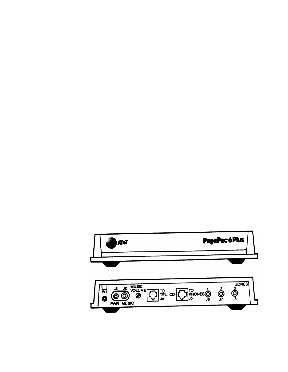
Front
Rear
PagePac® 6 Plus
1
Page 5
INSTALLATION
HOW TO INSTALL PagePac 6 Plus WITH ONE OR TWO TELEPHONE LINES
Installation Materials Required That Are Not Provided
—
Two half-modular, four-conductor telephone cords, length as required.
—
Two connecting blocks (type 42A).
—
Harris Dracon voice-coil speakers, or equivalent
NOTE: Use
Standard speaker cable and three RCA-type male phono plugs.
—
Standard installation tools (screwdriver, wire cutters, pliers).
—
(Optional) MusicMate, or other standard music source such as tape deck, FM tuner, leased
—
no more
source, etc.
than eight voice-coil speakers per zone.
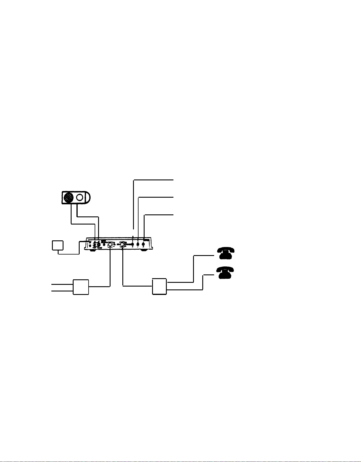
MusicMate™
Or Alternate Music Source
To AC Wall
Outlet
ll
To
Central
Office
Line 1
Line 2
Connector
Block
1
PagePac 6 Plus
Half-Modular
Cord
Connector
Block
Half-Modular
Cord
Zone 1 Speakers
Zone 2 Speakers
Zone 3 Speakers
. . . . To Extensions
. . . . To Extensions
2
NOTE: Use connection to J3 only with MusicMate.
Installation Procedure
1.
Connect PagePac 6 Plus to the incoming telephone line(s). Connections are shown on the
next page.
Connect the speakers to PagePac 6 Plus with RCA-type phono plugs.
2.
(Optional) You may connect a MusicMate or other music source (FM tuner, tape deck, leased
3.
source, etc.). If you use a source other than MusicMate, you will not use jack J3.
4.
Connect the power supply to an AC outlet (120 VAC, 60 Hz). The LED on the PagePac
6 Plus back panel (below the power cord) will illuminate.
Do not use an outlet that may
accidentally be turned off by a wall switch.
2
Page 6
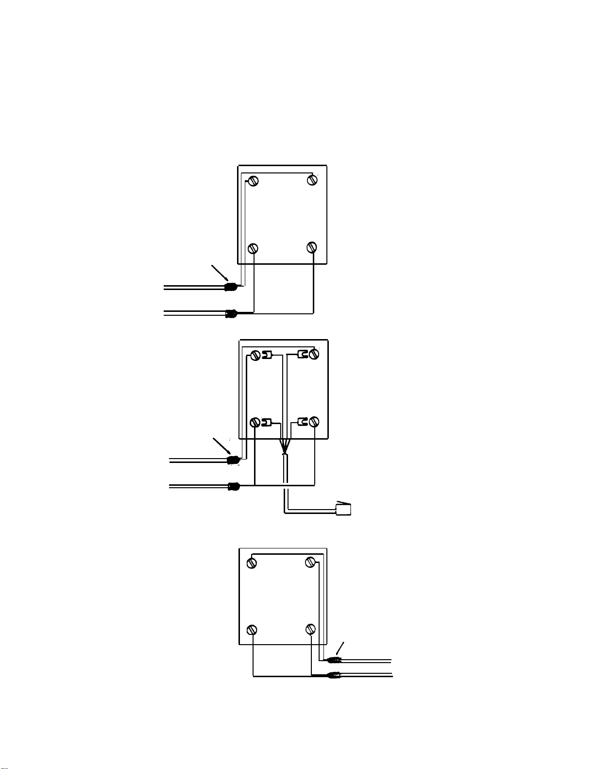
Wrap unused wire
around cable
To
Central
Office
FOR A SINGLE LINE—USE LINE 1 CONNECTIONS ONLY
Type 42A Connecting Block
G
Red
R
Install the first connecting
Green
block and attach the
incoming line(s) to the block.
Block 1
NOTE: See conversion
chart on next page, if you
Line 1
Line 2
B
Green
Y
Red
have 6-conductor wire.
Wrap unused wire
around cable
To
Central
Office
Line 1
Line 2
Type 42A Connecting Block
G
Green
B
Black
Line 2
Green
Red
Red
Green
Half Modular cord
Yellow
Line 2
Red
R
Y
Type 42A Connecting Block
G
Green
R
Red
Block 2
Attach the half-modular cord
to the block, and connect the
other end to PagePac 6 Plus.
To PagePac 6 Plus
“To Tel. Co. J4”
Install the second connecting
block and attach the line(s)
to the telephone(s).
B
Green Red
Wrap unused wires
Y
around cable
3
Line 1
Line 2
To
Phones
Page 7

Type 42A Connecting Block
G
Green
R
Green
Red
Red
Attach the second halfmodular cord to this block
and connect the other end to
Yellow
Line 2
Red
PagePac 6 Plus.
Y
Wrap unused wires
around cable
Line 1
Line 2
To
Phones
To PagePac 6 Plus
“To Phone J5”
Black
Line 2
B
Green
Half-Modular Cord
What If You Have 6-Conductor Wire?
If you have 6-conductor wire rather than the 4-conductor shown in the illustrations, use the table
below. It shows which conductors in the larger wire correspond to the red, green, yellow and black
conductors in the smaller wire.
4-Conductor Wire
Green
Red
Yellow
Black
—
—
6-Conductor Wire
White/Blue*
Blue/White
White/Orange
Orange/White
White/Green
Green/White
*The main color is listed first.
4
Page 8

CONNECTING SPEAKERS TO PAGEPAC 6 PLUS
Both standard speakers (indoor cone-type) and horn speakers may be used with PagePac 6 Plus.
For best perfomance, use only the type speaker recommended for your situation (see below),
and do not exceed the number of speakers or speaker run length maximums shown below.
Recommended Speakers
PAGING AREA
Open or Closed
Office Areas,
Conference
Room Etc.
Hallways
Private Office
Open Industrial
Area or Outdoors
Total Speakers
Max. Length of
Speaker Run
(24 AWG Wire)
MOUNTING LOCATION
On Wall or Ceiling
Above the Ceiling
On Wall or Ceiling
Placed on Desk or Wall
On Wall or Pole at Least
15 Ft. Above Ground
SPEAKER TYPE
Universal Cabinet
Recessed Ceiling
Universal Cabinet
Desktop or Wall
Horn
Speaker Limitations
STANDARD INDOOR SPEAKERS
24 (maximum 8 per zone)
100 Ft.
AT&T ORDER NO.
PEC 53511
COMCODE
PEC 53514
COMCODE
PEC 53511
COMCODE
PEC 53516
COMCODE
PEC 53512
COMCODE
HORN SPEAKERS
6 (maximum 2 per zone)
403307770
403307796
403307770
403307804
403307788
100 Ft.
*If using both horns and standard speakers in the same zone, each horn counts as four stand-
ard speakers.
In some situations you may be able to extend a run farther than 100 feet, by using fewer
speakers and/or larger wire.
5
Page 9

To Zone 3 speakers
To Zone 2 speakers
22050-910
(Optional)
Maximum 8 wall or ceiling speakers or
2 horn speakers per zone.
To Zone 1 speakers
Output
Cord
Adapter
(Supplied)
Rear
PagePac® 6 Plus
Speaker connections to PagePac 6 Plus
Required Materials
—
PagePac loudspeakers recommended for use with PagePac 6 Plus
24 AWG speaker wire
—
Standard installation tools—screwdriver, wire cutters/strippers, pliers, hammer, etc.
—
Installation Procedure
1. Install the speakers according to the directions supplied with them.
2. Connect each zone to the appropriate ZONES jacks on the PagePac 6 Plus (see above).
NOTE: Use RCA-type plug adapters (3) supplied with unit, to prepare speaker cable for
connection to zone jacks.
6
Page 10

OPERATION
OPTIONS—AND HOW TO SELECT THEM
You may select the following options for your PagePac 6 Plus.
●
Zone Paging—
of speakers in which the page will be heard. If you don’t want zone paging, you can set
the unit for all-call only (paging from all speakers).
●
Talk-Back—
NOTE: When talk-back is used in a noisy zone, we recommend no more than two talk-back
speakers be used in that zone. This reduces the problems caused by background noise. Talkback should normally not be used with all-call paging.
●
Talk-back Warning Tones—
talk-back is on. The INITIAL tone sounds once at the beginning of the page. The
REPETITIVE tones should sound every 15 or 30 seconds (your choice).
●
Confirmation Tone—
●
Background Music—
nate source such as a FM tuner, tape deck, leased source, etc.
●
Automatic Outside Line Access—
will have to wait either 2, 4, or 10 seconds depending on the option selected. The option
may also be turned off.
PagePac 6 Plus has three separate paging zones. Each zone is a specific group
Two-way communication between the telephone and speakers.
These tones are heard in the loudspeakers to let people know
A single tone heard in the telephone that indicates you can page.
You must provide a source of music. Use the MusicMate or an alter-
Connects you to the telephone line without dialing 9. You
Bottom View
The bottom panel of the PagePac 6 Plus
contains FCC information, and programming dial codes, as well as paging
and talk-back volume controls. The
music volume control and all connections
are on the back panel.
Rear
PagePac 6 Plus Bottom & Back Panels
7
Page 11

Setting Options
Pick up the telephone and
1.
listen for PagePac 6 Plus
dial tone (on key systems,
select the desired line first).
Dial the number for the op-
2.
tion desired (see the table to
the right), and listen for
program tone (two short
tones).
NOTE: If you hear reorder
tone (a fast busy tone), a
dialing error has been made.
Hang up and start over.
Replace the receiver.
3.
NOTE: This chart is also
in the bottom of the
PagePac 6 Plus chassis.
To select the desired option, dial the code shown.
OPTION
Confirmation tone - off*
Confirmation tone - on
Music in Zone 1 - on
Music in Zone 2 - on
Music in Zone 3 - on
Music in all zones - off*
Talk-back on Line 1 - off
Talk-back on Line 2 - off
Talk-back on Lines 1 and 2 - on*
Talk-back in Zone 1 - off
Talk-back in Zone 2 - off
Talk-back in Zone 3 - off
Talk-back in all zones - on*
Initial Talk-back Warning Tone - off†
Repetitive Talk-back Warning Tone - off*
Both Talk-back Warning Tones - on*
Time between Repetitive tones - 15 seconds
Time between Repetitive tones - 30 seconds*
All-zone paging - off
All-zone paging - on*
Automatic Outside Line Access
DIAL CODE
834
835
811
812
813
814
891
892
893
821
822
823
824
831
832
833
841
842
851
852
LINE 1
- off
- 2 sec.
- 4 sec.*
-10 sec.
LINE 2
- off
- 2 sec.
- 4 sec.
-10 sec.
*Indicates the default or factory-set condition for each option.
If power goes off, all options are reset to their default values.
†Check local regulations before shutting off either the Initial
or Repetitive talk-back warning tones.
8
861
862
863
864
865
866
867
868
Page 12

TONES YOU HEAR—AND WHAT THEY MEAN
In addition to the Confirmation tone and Talk-Back Warning tones already described, PagePac
6 Plus has several other tones that help you use the system.
Dial Tone—
PagePac 6 Plus dial tone serves the same purpose as the regular dial tone. It is
the first tone you hear after picking up the telephone
Busy Tone—
Reorder Tone—
PagePac 6 Plus busy tone indicates that the zone you want to page is in use.
Reorder tone is a “fast” busy tone. When you hear it, you have made some
error. Hang up and start over.
Program Tone—
Program tone is two very short tones. You will hear it after selecting an op-
tion. It indicates the option was successfully selected.
Call Waiting Tone—
Call waiting tone is two short tones (but longer than program tone). You
will hear it if a call comes in while you are paging.
HOW TO PAGE
You can page to all zones at once, or to a single zone or combination of zones. To page, pick
up the telephone and listen for PagePac 6 Plus dial tone, then dial the number for the zone
or zones you want. See below.
Paging Area
Zone 1
Zone 2
Zone 3
Zone 2 and 3
Zone 1 and 3
Zone 1 and 2
All Zones
Dial
1
2
3
4
5
6
7
When you replace the telephone, do so gently. This will prevent a “thud” from going out
over the speakers.
If talk-back is on, the voice of the person at the telephone controls the page/talk-back switch.
If this person speaks or makes any noise, anyone using talk-back will be cut off. After the
person at telephone is quiet, it takes about one-half second for the speakers to go into
talk-back.
HOW TO USE YOUR TELEPHONE
Incoming calls are handled normally. However, before making a call, you must either dial
9, or wait until you hear the regular dial tone.
Placing A Call:
Pick up the telephone and listen for PagePac 6 Plus dial tone (on key systems, select desired
1.
line).
2.
Dial 9, and listen for the regular dial tone. Or, you may wait for the regular dial tone.
If you want the operator, dial 0 as soon as you hear PagePac 6 Plus dial tone.
NOTE: If you hear Reorder Tone (a fast busy tone), a dialing error has been made. Hang
up and start over.
Dial the number.
3.
9
Page 13

Dialing 9 gives you regular dial tone immediately. If you wait, PagePac 6 Plus will timeout
and then provide regular dial tone. How long this takes depends on which Automatic Outside
Line Access time period you select.
NOTE: To dial emergency 911, dial 9 or
wait
for the regular dial tone, and then dial 911.
If a call comes in while you are preparing to page, but have not dialed the zone(s), the caller
will be connected directly to your phone (with no ring).
If a call comes in while you are paging, the page will be interrupted for a moment, and you
will hear Call Waiting Tone (two short tones). Hang up, and the phone will ring. You may
then answer the call normally.
Using Last Number Redial With PagePac 6 Plus
If your telephones have last number redial, you can use it with PagePac 6 Plus. The exact
procedure depends on whether or not your phone has a PAUSE button.
Example:
Lift the telephone handset (on a key system, select the desired line), and
1.
Without
A PAUSE Button
wait
for the
regular dial tone. Then, dial the number.
NOTE: The Automatic Outside Line Access should be set for 2 seconds. (Dial option
code 862 for Line 1, or 866 for Line 2.)
To redial:
Repeat Step 1, then press the redial button on the telephone (or on some phones, dial
2.
the redial code).
Example:
With
A PAUSE Button
To place initial call:
Lift telephone receiver and listen for PagePac 6 Plus dial tone.
1.
Dial 9.
2.
Press PAUSE button and dial number.
3.
To redial:
4.5.Lift the telephone receiver, listen for PagePac 6 Plus dial tone, wait for regular dial
tone (see Note under: “Without A PAUSE Button” above).
Press redial button (or on some phones, dial redial code).
NOTE: If you have problems using the “With A PAUSE Button” procedure, try the
“Without A PAUSE Button” procedure.
NOTE: Using PagePac 6 Plus with a PBX—
To prevent unintentional pages, connect
PagePac 6 Plus on a trunk that has a normally unused access code (for example, a
trunk that is accessed by dialing 8). This trunk may also be used for outgoing and
incoming calls.
10
Page 14
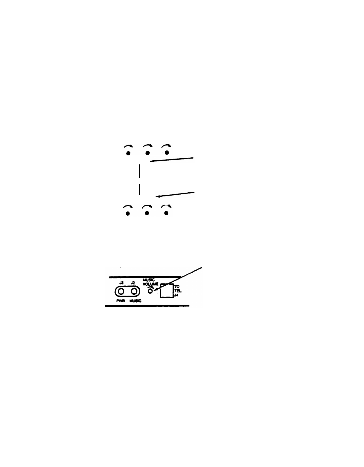
HOW TO ADJUST PAGE, TALK-BACK AND MUSIC VOLUME
You can control the sound volume of paging, music, and talk-back with these controls.
ZONE
ZONE
1 2 3
PAGE
VOLUME CONTROLS
TALK BACK
1 2 3
Bottom of Unit
PAGE VOLUME CONTROLS—
Controls page volume in indicated
zone; also affects music volume in
that zone. Adjust PAGE VOLUME
CONTROLS before adjusting
MUSIC VOLUME Control.
TALK-BACK VOLUME
CONTROLS—Controls volume of
talk-back from indicated zone.
MUSIC VOLUME—Controls
music volume in all zones
without affecting page volume.
Rear Of Unit
Page and talk-back volume controls for each zones are on the bottom of the unit. A single
music volume control, located on the rear panel, adjusts background music in all zones. Use
a miniature flat-blade screwdriver to set these PAGE AND TALK-BACK controls. DO NOT
force these controls past their stops. They rotate approximately 300 degrees.
NOTE: PagePac 6 Plus has an Operator Access feature. Whenever you dial “0” before selecting a paging zone, the unit will automatically place the call to the operator.
11
Page 15

FCC REGULATIONS PERTAINING TO THIS EQUIPMENT
FCC (PART 15)
Radio Frequency Interference
The PagePac 6 generates and uses radio frequency energy and if not installed and used in strict
accordance with the manufacturer’s instructions, may cause interference to radio and television
reception. Testing has been conducted for compliance with the limits for Class B device in accordance with the specifications in Subpart J of Part 15 of the FCC Rules. This testing is designed
to provide reasonable protection against such interference. However, there is no guarantee that interference will not occur in a particular installation. If this equipment does cause interference to
radio or television reception, which can be determined by turning the PowerMate unit off and on,
the user is encouraged to try to correct the interference by one or more of the following measures:
●
Reorient the radio or TV receiving antenna
●
Relocate the PagePac 6 with respect to the radio or TV receiver or vice-versa.
●
Plug the PagePac 6 into a different outlet so that it and the radio or TV receiver are on different
branch circuits.
If necessary, the user should consult the dealer or an experienced radio/television technician for
additional suggestions. The user may fined the following booklet, “How To Identify and Resolve
Radio-TV Interference Problems,” helpful. This booklet was prepared by the Federal Government
Printing Office, Washington, DC 20402. Stock order No. 004-000-00345-4.
FCC (PART 68)
This equipment is registered with the Federal Communications Commission (FCC) in accordance
with Part 68 of its Rules. The FCC requires that the manufacturer provide you with the following
information:
1. Connection and Use with Nationwide Telephone Network
The FCC requires that you connect your telephone equipment to the nationwide telephone network through a modular telephone outlet or jack. The modular telephone outlet or jack to which
the equipment must be connected is a USOC RJ1lC.
Registered equipment may not be used with Coin Telephone Lines. Equipment may be used with
Party Lines in areas where state tarifs permit such connections and when equipment is adaptable
for such use.
2. Information You May Need to Supply the Telephone Company.
Upon request of your local telephone company, you are required to provide them with the following information:
A. The lines to which you will connect the telephone equipment.
B. The FCC registration number and ringer equivalence number (REN). Both numbers are listed
on the equipment label. The REN is useful to determine how many devices you may connect to
your telephone line and still have them ring when your telephone line is called. In most, but not
all, areas, the sum of all RENs per line should be 5 or less. You may want to contact your local
telephone company. The local telephone company must also be notified upon final disconnection
of the equipment from the local telephone company lines.
12
Page 16

WARRANTY INFORMATION
LIMITED WARRANTY AND LIMITATION OF LIABILITY
AT&T warrants to you that the product will be free from defects in material and workmanship
when title passes to you. If you notify AT&T that the product has failed to operate as warranted
within one year of the date title passes to you, AT&T will, at its option, repair or replace the component or components of the product that failed to operate as warranted. Any repair or replacement components may be new or refurbished and will provided on an exchange basis. If AT&T
determines that the product cannot be repaired or replaced, AT&T will refund the purchase price
to you.
If you purchased the product directly from AT&T, AT&T will perform warranty repair on your
premises in accordance with the terms and conditions of AT&T’s “Business Day” or “Aroundthe-Clock” warranty plans. The details of AT&T’s warranty plans may be obtained from AT&T.
If you purchased the product from an authorized dealer, you will be covered by AT&T’s authorized
dealer warranty plan during the warranty period. Contact your authorized dealer for details of
AT&T's authorized dealer warranty plan.
above is your exclusive remedy.
The limited warranties provided above do not cover damages, defects, malfunctions or product
failures caused by:
●
Failure to follow AT&T’s installation, operation or maintenance instructions;
●
Unauthorized modification or alteration of the product or its components;
●
Product abuse, misuse or the negligent acts of persons not under the reasonable control of AT&T;
●
Actions of third parties and acts of God other than power surges (e.g., lightning).
AT&T's obligation to repair, replace or refund as set forth
This limited waranty applies only to the product purchased directly from AT&T or purchased directly
from an authorized AT&T dealer. This limited warranty does not apply to products purchased or
operated outside the United States.
You may be required to provide AT&T with proof of purchase before AT&T will perform any warranty repair or provide any warranty replacements.
EXCEPT AS SPECIFICALLY SET FORTH ABOVE, AT&T, ITS AFFILIATES, SUPPLIERS AND
DEALERS MAKE NO WARRANTIES, EXPRESS OR IMPLIED, AND SPECIFICALLY
DISCLAIM ANY WARRANTY OF MERCHANTABILITY OR FITNESS FOR A PARTICULAR
PURPOSE.
EXCEPT FOR PERSONAL INJURY, THE LIABILITY OF AT&T, ITS AFFILIATES, SUP-
PLIERS AND DEALERS FOR ANY CLAIM, LOSS, DAMAGE OR EXPENSE FROM ANY
CAUSE WHATSOEVER, REGARDLESS OF THE FORM OF THE ACTION, WHETHER IN
CONTRACT, TORT OR OTHERWISE, SHALL NOT EXCEED THE LESSER OF DIRECT
DAMAGES PROVEN OR THE REPAIR OR REPLACEMENT COST OF THE SYSTEM OR
THE SYSTEM'S PURCHASE PRICE. IN NO EVENT SHALL AT&T, ITS AFFILIATES, SUPPLIERS AND DEALERS BE LIABLE FOR INCIDENTAL, RELIANCE, CONSEQUENTIAL
OR ANY OTHER INDIRECT LOSS OR DAMAGE (INCLUDING LOST PROFITS OR
REVENUES SUSTAINED OR INCURRED IN CONNECTION WITH THE SYSTEM). THIS
LIMITATION OF LIABILITY SHALL SURVIVE FAILURE OF THE EXCLUSIVE REMEDY
SET FORTH IN THE LIMITED WARRANTY ABOVE.
INSTALLATION AND MAINTENANCE INFORMATION
There are several types of installation and maintenance plans available from AT&T and/or
your dealer. Please call your AT&T sales representative or authorized dealer for details.
For warranty service, contact your AT&T representative or authorized dealer.
13
Page 17

©Copyright 1988 AT&T
All rights reserved Printed in U.S.A.
999-500-212
Issue 1, Dec. 1988
 Loading...