

Page 1

Table of
Contents
585-310-231
Issue 2
December, 1995
INTUITY Integration with
MERLIN LEGEND
Communications System
Graphics © AT&T 1988
Page 2

Contents
Table of Contents iii
About This Document xiii
■ Purpose xiii
■ Intended Audience xiii
■ How This Book Is Organi zed xiii
■ Conventions Used xv
■ Trademarks and Service Marks xvi
■ Related Resources xvii
■ How to Make Comments Ab out This Book xix
1 MERLIN LEGEND Integration Concep ts 1-1
■ Introduction 1-1
■ Switch Integration Concepts 1-3
■ Intuity AUDIX Voice Mail Services 1-5
■ Intuity Intro Voice Re s ponse 1-7
■ Port Considerations 1-7
Intuity Port Administration 1-9
Dynamic Allocation or Shared Ports 1-9
Dedicated Allocation 1-9
■ Automated Attendant Enhancements 1-10
Primary and Secondary
Automated Attendant Concepts 1-10
Automated Attendant Operation Schedule 1-10
Automated Attendant Operation Based on
MERLIN LEGEND Status 1-11
Automated Attendant Operation
Based on Intuity AUDIX Business Schedule 1-11
Automated Attendant Holiday Operation 1-12
Automated Attendant Tenant Service Operation 1-12
Issue 2.0 Dece m b er 199 5 v
Page 3

Contents
Primary Automated Attendant Implementation
on the M ERLIN LEGEND Syst e m 1-12
Secondary Autom ate d Attendant Mode
Imp lem ent ati on on the M ERLIN LEGEND
System 1-13
Nigh t Only Operati onal Mo d e Implem ent atio n
on the M ERLIN LEGEND Syst e m 1-13
General Call Handling by the Intuity System:
Routing Table 1-14
■ Other Features of Particular Interest
for the MERLIN LEGEND System 1-19
Multi p le Autom ate d A tte n d ant s 1-19
Direct to Voice Mail (DVM) But t o n 1-19
■ Functionality Differences
for the MERLIN LEGEND System 1-20
2 Planning the Integ rati on 2-1
■ MERLIN LEGEND
Integration Planning 2-1
Application Names 2-2
Number Plan 2-2
Voice Ports 2-2
Intuity AUDIX Subscribers 2-3
Loop-Start Reliable Disconnect 2-3
Intuity System Trunks 2-3
Group Coverage 2-3
Group Calling 2-4
Restrictions and Allowed and Disallowed Lists 2-5
Night Service 2-6
■ Intuity System In t e g rati on Planning 2-6
Digits in Dial Plan 2-7
System Features 2-9
Channel Info rmat ion f or Instal lat ion 2-9
Assign S ervice to Called Num b e r 2-9
Ro uting Table 2-10
vi Issue 2.0 Decemb er 1995
Page 4

Contents
Business Schedules 2-14
Holiday Schedules 2-16
3 Implementing the Integration 3-1
■ Hardware Platform Installation 3-1
■ Hardware Platform Connection 3-1
■ Compl etin g the Software Installation 3-2
■ MERLIN LEGEND Initial Administration 3-2
■ Intuity Syste m Initi al Adm inist ra tio n 3-3
Perform Acceptance T es t ing 3-5
■ Administer and Test
Op ti onal Intui ty Packages 3-6
■ Adm ini ster Au tom at e d A ttend ant Enhancements 3-6
■ Ad m inister MERLIN LEGEND Syst em
for Cut-to-Service 3-7
■ Adm ini ster Networ king 3-8
4 Connectivity 4-1
■ MERLIN LEGEND
Voice Port Requirements 4-2
■ Intuity Syste m Connections 4-3
IVC6 Connections 4-3
Connect IVC6 Boards Using 885A Adapter: 4-3
Connect IVC6 Boards
Using 104A Connecting Blocks: 4-4
Connecting Serial Ports 4-5
Connecting Administration Ports
Within 50 feet, Same Power Outlet 4-6
Connect Admin Ports
More Than 50 feet/Diffe re nt Power Outlet 4-7
Connecting SMDR Ports
Within 50 feet, Same Power Outlet 4-11
Connecting to Serial Port 2 (COM2) 4-11
Issue 2.0 December 1995 vii
Page 5

Contents
Connecting to First Available Serial Port on
Multi-Port Serial Card 4-12
Connecting SMDR Ports
More Than 50 feet/Diffe re nt Power Outlet 4-13
Networking 4-18
Connecting Low-Speeed Digital Networking 4-18
Remote Maintenance 4-20
Remote Access 4-22
Dedicated Line Access 4-23
Connecting De dicat ed Lines within 50 Feet 4-23
Connecting De dicat ed Lines be yo nd 50 Feet 4-24
Remote Access (Dial-Up) Connections 4-28
5 MERLIN LEGEND Switch Admin istrati on 5-1
■ Disconnect Signaling Reliability 5-1
■ Group Coverage Member Assig nments 5-2
■ Group Calli n g Member Assignments 5-3
■ Group Calli ng Trunk or Pool Assignments 5-4
■ Hunt Type 5-5
■ Group Coverage Receiver 5-7
■ Group Type 5-8
■ Allowed List s 5-9
■ Assign A llowe d Lists to Intu ity Ports 5-10
■ Disallowed Lists 5-12
■ Assign Disallowed Lists to Intuity Ports 5-13
■ Assign Extensions for Night Service 5-15
■ Assign AUDIX Calling Group for Night Service 5-16
6 Intuity System Administratio n 6-1
■ Administering the Sw itch Inter face 6-1
Stopp i n g and Restarting the Voice System 6-2
viii Issue 2.0 December 1995
Page 6

Contents
■ Entering the Business Schedules 6-4
■ Entering the Holiday Schedules 6-6
■ Entering the Routing Table 6-8
■ Other Ad m inistrati o n 6-10
A System Security and Toll Frau d A-1
■ Pr otecting Your System A-1
Switch Security A-2
Security Tips A-2
Voice Messaging System Security A-3
Security Tips A-3
Automated Attendant System Security A-4
Security Tips A-5
■ Subscrib er Pa s sword Guidel ine s A-5
■ Switch Administration A-6
Restrict Outward Dialing A-6
Res trict Toll Areas A-6
Create Disallowed Number Lists A-6
Create Allowed Number Lists A-6
Restrict AMIS Networking Number Ranges A-7
■ Intuity AUDIX Administration A-7
Outcalling A-7
Mailbox Administration A-8
Basic Call Transfer A-8
■ Detecting Toll Fraud A-9
Call Detail Recording A-9
Intuity AUDIX Traffic Reports A-10
■ AT&T’s Statement of Direction A-10
AT&T Security Offeri n g s A-11
AT&T Toll Fraud Crisis Intervention A-12
AT&T Corporate Security A-12
Issue 2.0 December 1995 ix
Page 7

Contents
B Installing MERLIN LEGEND
Software on the Intuity System B-1
■ Requirements B-2
■ Procedure 1: Stop the Voice System B-2
■ Procedure 2: Load the
MERLIN LEGEND Software B-3
■ Procedure 3: Turn on Transfer Feature B-6
C Switch Administratio n for INTUITY Lodging C-1
■ Introduction C-1
■ Hunt Group Administration C-1
■ Message Retrieval Administration C-2
Message Retrieval in Lodging Syst em s with ou t
AUDIX C-2
Message Retrieval in Systems Shared with AUDIX C-2
Retrieval from the AUDIX Application C-2
Retrieval from the Lodging Applica tion C-2
Alternate Message Retrieval Metho d C-2
■ Voice Mail Administrati o n C-4
■ Call Coverage Path C-5
■ Do Not Disturb C-5
■ Cut-to-Service C-5
Gradual Cut-to-Service C-6
One-Step Cut-to-Service C-6
■ Summary C-7
x Issue 2.0 Dec e mber 1995
Page 8

Contents
ABB Abbreviations ABB-1
GL Glossary GL-1
IN Index IN-1
Issue 2.0 December 1995 xi
Page 9

Contents
xii Issue 2.0 December 1995
Page 10

About This Document
Purpose
This book,
585-310-231, contains information needed to integrate an Intui ty™ sy stem with a
MERLIN LEGEND
Intui ty Integration with MERLIN LEGEND Communications Syste m,
®
Communications System .
Intended Audience
This book is intended for system administrators, impleme ntors, on-site
technicians, and Remote Service Center personnel suppo rtin g the Intuity system.
How This Book Is Organized
This book is organized into the following chapters:
■ About This Document
This preface describes the book’s purpose, intended audiences,
organization, conventions, trademarks and service marks, and related
resources. This preface also explains how to make co mments about the
book.
■ Chapter 1, ‘‘MERLIN LEGEND Integration Concepts’’
This chapter describes the operation of the Intuity sy stem an d how it is
integrated with the MERLIN LEGEND Communication Syste m.
Issue 2.0 December 1995 xiii
Page 11

■ Chapter 2, ‘‘Planning the Integration’’
This chapter provides Intuity system and MERLIN LEGEND system
planning worksheets and a dministration forms to help record information
needed for the integration of the Intuity system and the MERLIN LEGEND
Communications System. It also explains how to fill out the forms.
■ Chapter 3, ‘‘Implementin g the Integration’’
This chapter describes the steps necessary to implement the integration
between t he MERLIN LEGEND system and the Intuity system, a n d
describes where to find each necessary procedure.
■ Chapter 4, ‘‘Connectivity’’
This chapter provides connection diagrams and instructions for physically
connecting the Intuity system to the MERLIN LEGEND Communi cat ions
System an d to other de vices as necessary for s ystem o p erat ion.
■ Chapter 5, ‘‘MERLIN LEGEND Switch Administration’’”
This chapter contains instru ctions f or using the System Programming and
Maintenance Utility (SPM) to enter the da t a on the fo rms completed in
Chapter 2.
■ Chapter 6, ‘‘Intuity System Administrat ion’’
This chapter contains instructions for administering the Intuity system for
use with t he MERLIN LEGEND Com munications System by en t ering d ata
on the forms co m p l e t e d in Cha p t er 2. Procedures are provided only for
MERLIN LEGEND system-specific items and for new Intuity feat ures not
described elsewhere.
■ Chapter A, ‘‘System Security and Toll Fraud’’
This app endix provides important information for securing the system
against telecommunications fraud. Review the information in this appendix
bef ore start i n g the swit c h int e g rati on p rocess.
■ Chapter B, ‘‘Installing MERLIN LEGEND Software on the Intuity System’’
This app endix contains procedures for installing the MERLIN LEGEND
switch integration software on the Intuity system.
■ Chapter C, ‘‘Switch Administ ra tio n for INTUITY L o dg ing’’
This app endix contains information about installing the M ERLIN LEGEND
switch integration with an Intuity system operating the Intuity Lodging
ap p lication.
■ Abbreviations
This section provides a list of abbreviations and acronym s used in Intuity
Voice Processing documentation.
xiv Issue 2.0 Dece m ber 1995
Page 12

■ Glossary
ENTER
The gl ossary provides a definition of terms and acronyms used in Intuity
Voice Processing documentation.
■ Index
The index provides an alphabetical listing of p rincipal subjects covered in
this book.
Conventions Used
The following conventions were used in this book:
■ Rounded boxes represent keyboard keys that you press.
For example, an instruction to p re ss the enter key is shown as follows:
Press .
■ Square boxes represent phone p a d keys that you press.
ENTER
For example, an instruction to p ress zero on the ph o n e p ad is shown as
follows:
Press .
■ The word
0
enter
means to type a value and press .
ENTER
For example, an instruction to type y and press is shown as follows:
Enter y to continue.
■ Two or three keys that you press at the same time (that is, you hold down
the first key while pressing the second and/or third key) are shown as a
rounded box that contains two or more words separated by hyphens. For
example, an instruction to press and hold while typing the le tter d is
ALT
shown as follows:
Press
■ Commands and text you type or enter appear in bold.
■ Va lues, instructions, and prompts that you see on the screen are shown as
ALT-d
follows:
Press any key to continue.
■ Variables that the system supplies or that you must supply are shown in
italics
. For example, an error message including one of your filenam es is
shown as follows:
The file
filename
is formatted incorrectly
Issue 2.0 Decemb er 1995 xv
Page 13

■ The sequence of menu options tha t you must select to displa y a specific
screen is shown as follows:
Begin at the INTUITY Administration menu, and select the following
sequence:
> Voic e System A d m inist rati o n
> Voice Equipme nt
In this exampl e, you would first access the INTUIT Y Administration menu.
Then you would sele c t the Voice Syste m Administration optio n to display
the Voice System Administration menu. From that menu, you would select
the Voice Equi pment option to display the Voice Equipment screen.
Trademarks and Service Marks
The followin g trademarked products may be mentioned in this book:
Product Name Company
AUDIX® Registered trademark of AT&T
COMSPHERE® Registered trademark of AT&T Paradyne Corp.
CONVE RSANT® Voice Information
System
Intuity™ Trademark of AT&T
MERLIN LEGEND® Registered trademark of AT&T
Paradyne® Registered trademark of AT&T
UNIX® Registered trademark of UNIX Systems
Registered trademark of AT&T
Lab oratori es, I n c .
xvi Issue 2.0 Dece m ber 1995
Page 14

Related Resources
In add i t ion t o this document, you may need to reference the following documents:
Document
Document
Number Issue
INTUITY™ Release 3.0 System Description
INTUITY™ Documentation Guide
INTUITY™ New System Plannin g for Release 3.0
INTUITY™ Release 3.0 Planning for Upgrades
INTUITY™ Release 3.0 Planning for Migrations
INTUITY™ Installation Checklist
INTUITY™ MAP/5 Hardware Installation
INTUITY™ MAP/40 Hardware Installation
INTUITY™ MAP/100 Hardware Installation
INTUITY™ Software Installati o n for Release 3.0
INTUITY™ Release 3.0 Upgrade Procedures
INTUITY™ Release 3.0 Migration Procedures
INTUITY™ Platform Administration and Maintenance for
Release 3.0
INTUITY™ AUDIX® Release 3.3 Administration and
Feature Op erations
INTUITY™ FAX Messaging Administrati on an d Addenda
585-310-232 1 or later
585-310-540 2 or later
585-310-605 2 or later
585-310-653 1 or later
585-310-652 1 or later
585-310-161 2 or later
585-310-146 2 or later
585-310-138 2 or later
585-310-139 2 or later
585-310-160 2 or later
585-310-164 2 or later
585-310-233 2 or later
585-310-557 2 or later
585-310-552 3 or later
585-310-558 1 or later
INTUITY™ AUDIX® Digital Networking Administration
AMIS Analog Networking
INTUITY™ Lodging Administration and Feature Operations
INTUITY™ Lodging Property Management System
Specifications
INTUITY™ Call Accounting System User Guide
INTUITY™ Call Accounting System Quick Reference
INTUITY™ Intro Voice Response and A ddenda
INTUITY™ Message Manager Release 2.0 User’s Guide
AUDIX® Administration an d D ata Acquisition Package
585-310-533 2 or later
585-300-512 6 or later
585-310-559 1 or later
585-310-234 1 or later
585-310-728 1 or later
585-310-729 1 or later
585-310-716 1 or later
585-310-731 1 or later
585-310-502 4 or later
Issue 2.0 December 1995 xvii
Page 15

INTUITY™ Integrati on with System 75 and DEFINITY®
Communications System Generic 1 and Generic 3
585-310-214 4 or later
INTUITY™ Integrati on with System 85 and DEFINITY®
Communications System Generic 2
INTUITY™ Integrati on with MERLIN LEGEND®
Communications System
INTUITY™ Integrati on with the 5ESS® Switch
INTUITY™ Integrati on with DMS-100
INTUITY™ Integrati on with Northern Tele com® SL-1,
Meridian™, and Meridian SL-1
INTUITY™ Integrati on with Mit el™ SX-200® DIGITAL, SX-
100®, and SX-200®
INTUITY™ Integrati on with NEC® NEAX™
INTUITY™ Integrati on with ROLM™ 8000, 9000, 9571
INTUITY™ Lodging Artwork Package
Voice Messaging Quick Reference
A Portable Guid e to Voice Messaging
INTUITY™ Voice/FAX Messaging Quick Reference
INTUITY™ Voice/FAX User Guide
585-310-215 2 or later
585-310-231 2 or later
585-310-219 1 or later
585-310-223 1 or later
585-310-221 2 or later
585-310-222 2 or later
585-310-216 2 or later
585-310-220 2 or later
585-310-739 1 or later
585-300-702 3 or later
585-300-701 3 or later
585-310-734 1 or later
585-310-733 1 or later
Multiple Personal Greetings Quick Reference
Voice Messaging Wallet Card
Voice Messaging Outcalling Quick Reference
Voice Messaging Business Card Stickers
INTUITY™ AUDIX® R3.3 Voice Messaging Subscriber
Artwork Package
INTUITY™ AUDIX® R3.3 Voice/Fax
Messaging Quick Reference–Canadian French
INTUITY™ AUDIX® R3.3 Voice/Fax
Messaging Quick Reference–British English
INTUITY™ AUDIX R3.3® Voice/Fax
Messaging Quick Reference–Latin Spanish
INTUITY™ AUDIX R3.3® Voice/Fax
Messaging Quick Reference–Greek
INTUITY™ AUDIX R3.3® Voice/Fax
Messaging Quick Reference–Mandar in
585-300-705 5 or later
585-304-704 2 or later
585-300-706 1 or later
585-304-705 2 or later
585-310-735 1 or later
585-310-734FRC 1 or later
585-310-734ENB 1 or later
585-310-734SPL 1 or later
585-310-734GK 1 or later
585-310-734CHM 1 or later
xviii Issue 2.0 December 1995
Page 16

INTUITY™ AUDIX R3.3® Voice Messaging Subscriber
Artwork Package British English
585-310-739ENB 1 or later
INTUITY™ AUDIX® R3.3 Voice Messaging Subscriber
Artwork Package Canadian French
INTUITY™ AUDIX® R3.3 Voice Messaging Subscriber
Artwork Package Latin Spanish
INTUITY™ AUDIX® R3.3 Voice Messaging Subscriber
Artwork Package Greek
INTUITY™ AUDIX® R3.3 Voice Messaging Subscriber
Artwork Package Mandarin
INTUITY™ AUDIX® R3.3 Voice Messaging Subscriber
Artwork Package Japanese
INTUITY™ AUDIX® R3.3 Voice Messaging Subscriber
Artwork Package U.S. En glish (A4 Sizing)
How to Make Comments About This Book
A reader commen t card is behind the title page of this book. While we have tried
to make this boo k fit your needs, we are interest ed in your suggestions for
improving it and urge you to c o mplete an d retu rn a reader comment card.
If the reader comment card has been removed, send your co m ments to :
585-310-739FRC 1 or later
585-310-739SPL 1 or later
585-310-739GK 1 or later
585-310-739CHM 1 or later
585-310-739JA 1 or later
585-310-739A4 1 or later
AT&T
Product Documentation Development Department
Room 22-2C11
11900 North Pecos Street
Denver, Co 80234
Please include the title and order number of this book.
Issue 2.0 December 1995 xix
Page 17

MERLIN LEGEND Integration Concepts
This chapter contains information that d escribes the Intuity system and explains
how the Intuity system and the MERLIN LEGEND Communica t ions System work
toget her.
1
Introduction
The AT&T Intuit y AUDIX® Voice Mail System (Intuity A U DIX) and the AT&T Intuity
Intro Voice Resp onse System (Intuity IVR) provide business-oriente d,
comput erized voic e services in support of a telecommunications system.
The Intuit y system uses voice promp ts and announcements to g uide c allers in
sending and receiving voice messages through the use of touch-tone buttons on
the ca ller’s tel ephone. Intui ty AU DIX ca n b e use d as a personal answering
service, a messenger to individuals or groups, an information service, an office
receptionist, and as an autom at ed attendant service. Intuity Intro Voice
Resp onse can be used to develop sophisticated voice applic at ions tailored for a
specific customer.
Intuity AUDIX and Intuity Intro Voice Response are soft ware app lication
packages that build upon the Intuity service layer and the Intuity processing
platform layer. (Refer to Figure 1-1.) The elements of the Intuity service layer and
the Intuity processing platform layer are accessible to any ap plication package
above them. By putting common elements such as switch integration, digital
networking, voice processing, call control, and system administrat ion int o the
service layer, these faci lit ies can be used by all current and future application
packages.
Issue 2.0 Dece mber 1995 1-1
Page 18

Developing the Intuity system with the processing platform layer as its base
keeps reliability and maintainability as a focus throughout the product. The
processing platform layer cont ains uti lities and tools that the layers above it can
use, such as alarm processing, backup and restore utilities, activity logs, and the
operation, administration, and maintenance interface. The h ardware of the
processing platform layer inclu des the Multi-Application Platform (MAP) chassis
with the central processing unit (CPU), memory (RAM), hard disk drive(s),
removable media drives (f loppy diskette and tape) and the UNIX operati ng
system.
The service layer includes the voice processing platform, Intuity AUDIX Digital
Networking, and switch i ntegration. The service layer is similar to the processing
pla tform layer in th at it provides to ols and utilities to the applications packages,
but it is more specific in its offerings. The service layer includes hardware and
software co m ponents integral to the services offered the IVC6 voice card for
processing speech, the AU DIX communications controller for Intuity (ACCX) card
for digital networking, and system administration software for elements that span
the plat form su ch as voice port administration.
The a pp lication package layer contains independent programs that meet a
specific business need. The Intuity AUDIX Voice Mail System relies heavily on the
foundation established b y the services and p rocessing p latform layers
.
Application Package Layer
Intuity AUDIX Voice Mail Intuity Intro Voice Response
Voice Mail Administration
Subscriber Database
Message Database
Transaction Definition Environment
Voice Response Database Access
Speech Administration
Service Layer
Voice Processing Platform
Speech Recording/Playback
Call Control
System Administration
Intuity AUDIX
Digital Networking
Network Administration
File Transfer
MERLIN LEGEND
Switch Integration
Provides Call Information
Transfers Calls
Processing Platform Layer
Event Handling
Alarm Processing
Backup/Restore
Activity Logs
Remote Console
Process Management
Operation, Administration,
and Maintenance Interface
Feature Administration
UNIX Operating System
Figure 1-1. Intuity System Layers
1-2 Issue 2.0 December 1995
Page 19
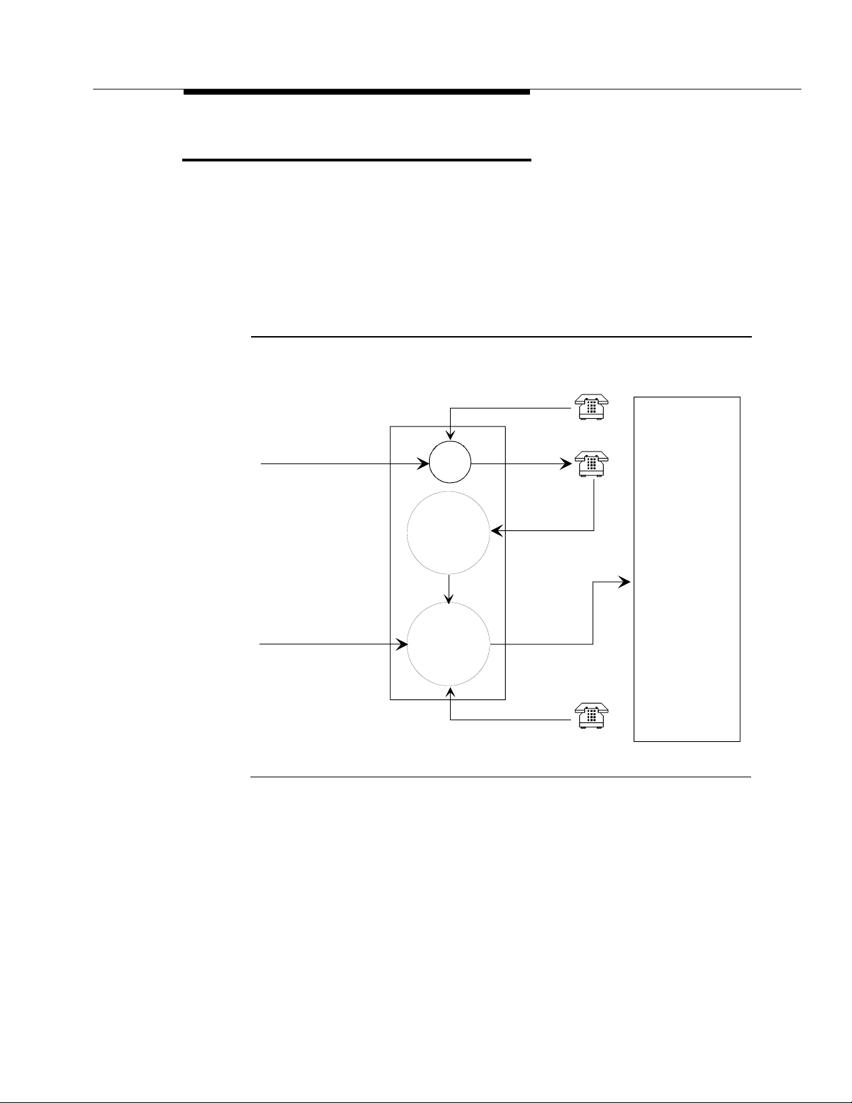
Switch Integration Concepts
Switc h integ ration
messagin g system and a switch in order to provide a seamless interface to
callers and subscribers. A fully integrated voice messagi ng system uses
information taken directly from the switc h to determ ine how to process each
incoming phone call. (Refer to Figure 1-2.) Integrating the Intuity system and a
MERLIN LEGEND switch do e s not r e q uire special equipmen t — the MERLIN
LEGEND sy st e m sends ca ll information by touch-tones over the same voice
circuits used for call processing.
refers to the sharing of information between a voice
MERLIN LEGEND
Communications System
Local Call
Intuity System
Coverage
Local
Station
Trunk Call
Coverage
Outside
Coverage
Group
Coverage Path
Trunk Call
Figure 1-2. Call Routing
Integrated
VMI
Calling
Group
Tip/Ring
Station Line
Direct
Outside
Direct
Local Call
Local
Issue 2.0 December 1995 1-3
Page 20

To understand how Intuity s ystem a p plications are integrated with the MERLIN
LEGEND Commu nications Syst em, the followin g d e f ini tions wi ll be usef ul (more
det aile d d e f ini tio ns are available in the MERLIN LEGEND Communications
System d oc um e ntat io n ):
■ Coverage Path
When a call is not answered because the called station is busy or
because the called station has not answered within a specifi ed number of
rings, the call is sent to the next point in the coverage path. This may be a
secretary, an attendant, etc. The last, or possibly only, coverage point is a
calling group that sends calls to the Intuity AUDIX system.
■ Coverage Group
Group coverage is an arrangement in which a special coverage group
act s as a rout ing point for a group of extensions whose coverage is
handled in the same way. Calls that are not answered by a member of the
coverage group are sent to the Intuity AUDIX system by programming a
voice messaging interface (VMI) calling group as the receiver for the
coverage group.
■ Voice Message Interface (VMI) calling group
A VMI calling group has the following characteristics:
— Calls to the group extension ring at the first available station. (That
is, each call rings at the first available station from the beginning of
the list of st a tio n s.) This is c a l led “ l inear hunt .”
— Trunks can b e set to “ring in” to the calling group so that an
incoming trunk call goes directly to the first available station.
— The calling group can be programmed as the receiver for a
coverage group so that unanswered calls to the members of the
coverage group automatically go to the first available station for
coverage.
—An
integrated
VMI calling group provides call information to the
voice port receiving each call. The call information allows the Intuity
AUDIX system to determine:
■ If the call being processed was a direct call or a coverage
call
■ I f th e call was a direct inside call (to the c allin g group
number) or a direct outside call (on one of the trunks
assigned to ring into the calling group)
■ If the coverage is for one ext ension calling another, or for a
call made from outside (trunk) to an extension
NOTE:
In a
generic
VMI calling group, call information is not supplied. A
generic VMI group is used for Intuity IVR a pplications only.
1-4 Issue 2.0 December 1995
Page 21

Coverage for calls i s p ro vi ded b y assigning a call
point of each extension’s co verage p a th. The calling group for the Intuit y voice
ports is then programmed as the receiver for the call coverage group.
Additio nal informa tion req uired for coordination of the Intuity system and the
MERLIN LEGEND system is passed in both directions by touch-tones. The Intuity
system and the M ERLIN LEGEND system also communicat e by switc h -hook
flashes and call progress tones.
Some features provided on other AT&T switches do not have corresponding call
informatio n on the MERLIN LEGEND system. For examp l e, on DEFINITY/System
75 switches, a code indicates whether the reason for coverage is BUSY or NO
ANSWER. As a result, the Intu ity syst em can provide different personal greetings
based on this information on the DEFINITY/System 75, b ut not on the MERLIN
LEGEND sy st e m . Simi larly, t he Day Ser vic e/Night Service feature available on
the MER LI N LEGEND system ca n not be p rovided on the DEFINITY/System 75.
Intuity AUDIX Voice Mail Services
Intuity AUDIX is easy to operate. Callers receive spoken promp ts to g u i d e them
in making choices by pressing the appropriate t ouch-tone button on the
telephone.
Intuity AUDIX can be administered to provide the following kinds of services
(examples):
coverage group
as the last
■ Call Answer
When the extension originally ca lled is busy or there is no answer, Intuity
AUDIX allows the caller to leave a message, transfer to another extension,
or transfer to an attendant. The person called (sub scriber) may provide a
personal greeting to callers o r select a standard system greeting. The
subscriber may set up a password to help protect against unauthorized
access to messages. Messages can be picked up from the office or from
an outside telephone.
The outcalli ng feature allows Intuity AUDIX to call a subscriber when a
new messa g e arrive s. The su bscriber can specify the telephone or pager
number to be called.
The call is passed from the MERLIN LEGEND system to the Intuity s ystem
with c all inf orma tio n that indicates the co ve red extension number and
whether the call was from an internal station or received on a trunk from
outs i de. Based on this information and on c aller a c t ions i ndicated by
pressing touch-tone buttons, the Intuity system can accept a message for
the called extension’s voice mailbox or provide other special processing.
Issue 2.0 December 1995 1-5
Page 22

■ Voice Mail
Voice mail services allows subscribers to send voice messages to other
subscribers, listen to received messages, forward messages received
with comments attached, reply to messages, and return calls to oth er
subscribers who left messages. Subscribers can create and edit group
lists an d send messages to one or more groups.
Voice mai l services also allow the system manager to send broadcast
messag es to everyone on the system.
When a subscriber has “new” voice messages in their mailbox, voice mail
turns on the sub scriber’s m essage waiting indicator.
Voice mail may be accessed from internal stations by diali n g the
extension for the calling group t hat contains the Intuity system voice ports
or from outside by calling in on a trunk that is administered to ring at the
Intuity system voice port calling group.
The call is passed from the MERLIN LEGEND system to the Intuity system
with c all inf orma tio n that indicates the c a ll was received d irectly in the
calling group and includes the calling extensi on nu m b er or trunk num b er.
■ Automated A ttend ant
An automated attendant directs callers through a series of menu
selections to reac h a d esired d epartment, extension, or attendant. Callers
are greeted wit h s p oken prompts that guide them in pressing touch-tone
buttons to connect to their desired destination. If there is no answer or the
desired extension is busy, the caller may leave a message or transfer to
an atten d ant .
An automated attendant can be used in a primary call handling mode or a
secondary call handling mode:
— In primary call handling mode, the automated attendant answers
incoming calls as they are received. A receptionist ba ck s u p the
automated attendant by handling overflow calls an d c alls from
people needing assistance (for example , time-outs and d ial 0).
— In secondary call handling mode, a receptionist answers as many
calls as possible and the automated attendant handles any
overflow c alls.
The Intuity system allows multiple automated attendants. Each automated
attendant may have separate menus fo r day and night service and custom
service for special hours and for holidays.
The call is passed from the MERLIN LEGEND system to the Intuity system
with c all inf orma tio n that allows the I ntu ity s ystem to provide automated
attendant processing based on the trunk on which the call is received
and/or on the number that was called.
1-6 Issue 2.0 December 1995
Page 23

■ Bulletin Board Service
Bulletin Board service (also called Information service) is a call-in
information facility. The caller hears a prerecorded, infor mat ional message
and is then disconnected.
The call is passed from the MERLIN LEGEND system to the Intuity s ystem
with c all inf orma tio n that allows the I ntu ity s ystem to provide information
service processing based on the trunk or extension on which the call is
received.
Alternately, bull etin board service can provide multiple messages by
using a menu within an auto mat ed attendant.
Intuity Intro Voice Response
Intuity IVR is an application development environment or toolkit for building
customized business applications. Calls are routed to the Intuity IVR application
based on specific numbers called (within a shared calling group) or by using a
de dicat e d calling group for the app lication.
Por t Considera tions
The MAP/5 a nd the MERLIN LEGEND system each impose some limitations on
the number and arrangement of voice ports when used with the Intuity system.
The choice of how to implement these ports may b e based in part on the
following hardware c o n straint s:
■ The MAP/5 is lim ited to a maximum of 18 voice channels wit h up to four
di g ital networking channels. (This is a physical space limitation.)
NOTE:
For the MAP/40 and MAP/100, the MERLIN LEGEND system
restrictions described in the following b u l let are the only lim itin g
factor.
■ Intuity hardware considerations aside, MERLIN LEGEND calling g roups
can contain a maximum of 20 extensions for voice ports. A maximum of 20
voice channels are su pporte d for all applications connected to a single
calling group. If more than one calling group is used, a total maximum of
24 voice channels distributed am ong several groups are supported.
!
CAUTION:
All Intuity AUDIX voice ports must be in the same calling group.
Issue 2.0 December 1995 1-7
Page 24

Because of these constraints, the channel assignment strategy for the Intuity
syst e m wi t h the MERLIN LEGEND s ys t e m may differ considerably from the
strategy that would be used with other switches where these constraints are not
present. In particular, the types and volumes of call traffic may allow alterna tive
approaches. The following strategies can be used:
■ Single Group of Shared Ports
A single group of shared ports is the simplest, most flexible and p owerful
strategy from a traffic handling point of view, but it is limited to one calling
group with a maximum of 20 ports. If no Intuity IVR applications are
installed on the system ( tha t is, only Intuity AUDIX is used), you should use
this arrangement.
NOTE:
Intuity AUDI X and Intuit y IVR calls are directed to the same calling
group. The call s ar e t hen handled based on the c alled numb er
information.
A single calling group allows the Intuity system to use idle channels to
meet the immediate needs of any type of incoming call. The Intuity system
det erm ines its resource allocation based upon current demand. All
channels may respond to any call by identifying the number that has been
called, associating it with the requested service, and providing the
requested service.
A single calling group must be defined on the M ERLIN LEGEND system
integrated
as an
■ Shared Port s Group with a Ded icated Ports Group
VMI calling group.
A dedicated calling group reserves ports and trunks for specific
ap plications, guaranteein g avail ability regardless of other traffic. It is
useful only for a single Intuity IV R application.
Calling groups that contain only Intuity IVR ports and trunks for a single
Intuity IVR application must be defined on the MERLIN LEGEND system
generic
as
VMI callin g groups.
NOTE:
The use of a dedicated ports calling group is the only way that more
than 20 p orts can be used on a MERLIN LEGEND system. A
maximum of 24 p orts total can be used on the MAP/40 or MAP/100.
A maximum of 18 p orts total can b e use d on the MAP/5.
1-8 Issue 2.0 December 1995
Page 25

Intuity Port Administration
NOTE:
Intuity p ort ad mi nistrat ion c on si sts of two steps:
1. Defining the extension associate d with a physical port (c hannel ) a nd the
initial service associated with that port (DNIS_ S V C or dedicated Intuity IVR
application)
2. Defining the service associated with a specific called number when the
initial service is DNIS_SVC (dedicated Intuity IVR application or AUDIX)
Do no t confuse DNIS_SVC (a speci fic value used in a fie ld for Intu ity system
channel servic e s pecification) and DNIS as it relates to T1 trunk service
available on the MERLIN LEGEND Communications System.
Dynamic A lloc atio n or Sha red Ports
With dynamic allocation or shared ports, the processing assigned to each call is
based on the Dialed Number Information Service (DNIS) information (call
information) included with t h e call. In this case, the calling group must be defined
integrated
as an
port (channel) must have DNIS_SVC def i ned a s its a ssociated service.
A service assignment table is then defined to associate the called number (or
trunk) with its final processing destination. For each specific called number (or
trunk), an Intuity IVR application name can be specifi ed. A t the end of the table,
the entry ANY in the called number field and the service AUDIX are used to send
all cal ls not oth erwise processed to Intuity AUDIX for processing.
VMI calling group on the MERLIN LEGEND system, and each
Dedicated Al loc at ion
With dedicated ports, the processing assigned to each call is based on the port
(channel) on which the call is received. The Intuity IVR calling groups must be
defined as a
each port (channel) must have a sp ecific Intuity IVR a pplication defined as its
associated service. There is no service assignment table required, and there is
no call information passed from the MERLIN LEGEND system to the Intui ty
system.
generic
VMI calling group on the MERLIN LEGEND system, and
Issue 2.0 December 1995 1-9
Page 26

Automated Attendant Enhancements
A numb er of autom at e d at te ndant enhancements have been made to Release
2.0 of Intuity AUDIX to meet customer needs and to provide feature p arity an d
migration paths for customers using the AT& T AUDIX Voice Power system on the
MERLIN LEGEND system. These new features include:
■ A map pi ng table that can be used to route incoming calls to automate d
atten dants based on the incomi n g Trunk ID
■ Automated at ten dant operat ion based on b usiness schedule(s)
■ Automated at ten dant operat ion base d on switc h Ni g ht Service stat u s
■ Automated at ten dant operat ion base d on holiday schedule(s)
This section describes the various w ay s the Intuity AUDI X automate d attendant
service can be set up to meet sp ecific call handling needs.
Primary and Secondary
Automated Attendant Concepts
A business can deploy automated attendant service in either primary or
secondary mode.
■ Primary Mode
In primary mode an automated attendant system is expected to answer all
incoming calls. The company receptionist backs up the automated
attendant by handling overflow ca lls and calls from people needing
assistance such as timeouts or dial .
■ Secondary (Backup) Mode
In backup mode the company receptionist is expect ed t o answer as many
calls as possible. The automated attendant service backs up the company
receptionist by handling calls he/she is unable to answer.
Automated Attendant Operation Schedule
Customers may use the Intuity AU DIX automate d at tendant service to answer
incoming calls on a 24-hour/day basis or at night only, depending upon their
business needs. Typically businesses are considered open during the day and
closed during the night. The term
night
business is open and
indicates the hours during which the business is
closed.
day
0
indicates the hours du rin g which the
1-10 Issue 2.0 December 1995
Page 27

Intuity AUDIX can use its own weekly business schedules to d et ermin e hour s for
day and night operation or it can rely on the telephone system to indicate when it
should operate in d ay mode an d when in n i g ht mode. The MERLIN LEGEND
system can provide d ay/ni ght status to Intuity AUDIX. Some other telephone
systems cannot.
Some businesses require the automated attendant to p lay a d if feren t menu
and/or handle calls slightly differently d uring lunch time. Other businesses may
need a transition automated attendant to handle callers from other time zones.
The alternat e service hour s feature provides a way to do this. This feature is
independent of whether the business schedule is set to follow the telephone
system night service status.
Automated Atten dan t Op e ration Based on
MERLIN LEGEND Status
The MERLIN LEGEND system can be administered to switch from day mode to
night mode operation either by a schedule administered on the system or by
pushing a Night Service bu tton on the at ten dant console. The advantage of
linking Intuity's automat e d at ten dant service schedule to the MERLIN LEG END
system status is that the two are then gu a ra ntee d to b e synchronized .
NOTE:
The ME RLIN LEGEND system can be programmed to route calls differently
when Nig ht Service is in effect . This feature can be used to provide
automate d atte n d ant service only when the MERLIN LEGEND t e leph one
system is in Night Service mode.
Automated Attendant Operation
Based on Intuity AUDIX Business Schedul e
Some businesses de-couple their automated attendant op erati on from the
telephone system's Night Service status and instead control it by the Intuit y
AUDIX weekly business schedule. Each Intuity system can have up to four
weekly business schedules (for example, the Sales and Service d i vi sions may
have com pletely different work schedules). In e a c h of the four schedules, the
administrato r can specify whether the telephone system Night S ervice status is to
be followe d or if entries in the schedule are to be followed. This gives the
flexibility needed for the sales division to follow a weekly business schedule for
its automated attendant service and for t he services division t o use the telephone
system Night Service status to control its aut omated attendant service.
Issue 2.0 December 1995 1-11
Page 28

Businesses can also specify alternate service h ours for additional fl exibility. This
allows businesses to handle calls more professionally during lunch time. It can
also be used by an organization s p read across several time zones to handle
calls appropriately when one location is closed but the o ther is open. Businesses
can use the MERLIN LEGEND system Ni g ht Servic e statu s to d rive the
auto mated attendant operation b ut still use the weekly business schedule for
alternate service hours op e ration.
Automated Attendant Holiday Operation
Most businesses would like to play different greetings and handle calls differently
on holidays. Intuity AUDIX system allows customers to use four different holiday
schedules. Each holiday schedule can include up to 26 holidays and the
automated attendant (mailbox) to be used for each of those holidays. This allows
customers to use a different holiday schedule for the sales di vi sion (o pened on
Columb us d a y) an d the services division (closed on Columbus day). It also
allows them to administe r d if feren t aut oma t ed attendant greetings and menu
opt ions for each of those holidays.
Automated Atten dan t Ten an t Serv ice Op e ration
So me time s a single telephone s ystem and voice messaging system is shared by
several small businesses, or a b usiness has several divisions under the same
roof. Intuity AUDIX can provide superior automated attendant service in these
cases by creating multiple main-level automated attendants and routing specific
calls to each de p ending on which trunk the call arrives on.
Primary Automated Attendant Implementation
on the MERLIN LEGEND System
When a business uses the Intuity AUDIX automated attend ant service in primary
mode, calls are administered to ring immediately at the Intuity AUDIX automated
attendant service. This is d one b y adm inistering the trunks to ring at a MERLIN
LEGEND int egrated VMI calling group (a special type of calling group) whose
mem bers are the Intuity system voice ports.
The MERLIN LEGEND system sends the trunk number to Intuity AUDIX for direct
(non-coverage) external calls. The Intuity AUDIX routing table maps the trunk
numbers received from the telephone system to the automat ed attendant
mailbox numbers.
1-12 Issue 2.0 December 1995
Page 29

Customers may want to pla y d i fferent automat e d atten dant g reeti ngs and/or
handle calls differently during day and night times. This is done by specifying
diff erent aut om at e d att e n d ant mail boxes for day and night times in the
auto mated attendant routing table. The routing table also allows customers to
specify an automate d at tendant mailbox for handling calls during the alternate
service hours.
Secondary Aut om ated Atten dan t M ode
Implementation on the MERLIN LEGEND
System
Automated A tte n d ant service ma y b e used in secondary mode to back up the
receptionist. Intuity AUDIX identifies coverage calls for the receptionist and
routes these calls to an appropri ate aut om ate d atte ndant mailbox. Anyti me an
external coverage call is received, Intuity AUDIX uses the appropriate
automated attendant mailbox number in the routing table as the called party,
taking int o account holidays and time of day. If no matching entry is found, the
called party number received from the telephone s y stem is used to provide
standard Call Answer service.
This scheme allows a business to play different greetings and menus depending
on whether the telephone system is in day or night mode, even when the
automated attendant service is configured to operate in backup m ode.
Night Only Operational Mode Implementation
on the MERLIN LEGEND System
Some businesses use automated attendant service only when the business is
closed. The MERLIN LEGEND system is ad minist ered to send c alls to the Int uit y
AUDIX c a lling group when MERLIN LEGEND system N ight Service feature is
act ivate d .
A business may want night time calls to go to a night service operator . Only when
this op erato r is unable to answer these call are they redirected to the Intuity
AUDIX system. This can be implemented by specifying the night service
operator as the Night Service answering position on the telephone system side
and then covering this answering position with Int uit y AUDIX . The routing table
can be used to map the night service answering position extensi on to an
automated attendant mailbox.
Issue 2.0 December 1995 1-13
Page 30

General Call Handlin g by the Intuity System:
Routing Table
As di scu sse d in "Port Considerations" earlier in this chapter, calls for Intuity
AUDIX are processed through DNIS_SVC. In tuit y A UD I X then processes the ca ll
based on the called number as follows:
■ If the called number is defined as a regular voice mailbox, call answer
service is provided.
■ If the called number is defined as a bulletin board extension, bulletin
board service is provided.
■ If the called number is defined as an automated attendant mailbox,
automated attendant service is provided.
To expand upon the possibilities for incomin g calls, three special tables are
used. The matching and substitution sometimes come from the same table and
sometimes from different tables. (T h is is clearer i f you refer to the processing flow
chart in Figure 1-3.)
■ Routing Table
The routing table is provided for the following reasons:
— To specify different automat e d attendant menus for calls on
different trunks
— To specify different call handling by automated attendants based
on a business sc hedule or the switch night service status
— To provide special ized call handling for holidays
— To provide voice mail login service for calls on specific trunks
The routing table can have u p to 25 entries. Each ent ry has the following
columns:
— Inc omin g Call e d Num ber (or rang e)
— Business Schedule
— Holiday Schedule
— Day Service Mailbox
— Night Service Mailbox
— Alternate Service Mail box
1-14 Issue 2.0 December 1995
Page 31

Each incoming call is matched to the Incoming Called Number
column in the routing table:
1. If an incoming call is to one of the numb ers in the ta b le, further
examination is made of Business Schedule and Holiday
Schedule columns. Otherwise, the call is passed directly to Intuity
AUDIX.
2. If the speci fic tag, “login” in the Business Schedule column is
found, th e call information is altered to cause the call to b e passed
directly to voice mail and receive login service when it reaches
Intuity AUDIX.
3. Next, the current date is matched against the Date c o l umn of the
holiday schedul e, if any, specified in the Holiday Schedule
column of the routing ta ble. If the date matches a holiday, the
automated attendant extension specified in the Mailbox column of
the holiday schedule is substitut e d for the original called number
and the call is passed to Intuity AUDIX.
NOTE:
The substitution is from the holiday schedule.
4. If a holiday m atch is not found, the current time is matched against
the Alternate Service Hours columns for the current day of
the week in the business sc hedule, if any, specified in the
Business Schedule colum n of the routi ng tab l e. If the current
time is within the s pecified range, the automated attendant
extension specified in the Alternate Service Mailbox column
of the routing table is substituted for the original called number, and
the ca ll is pa s sed to Intuity AUD IX.
NOTE:
The substitution is based on the business schedule, but is
from the routing table, not from the business schedule.
5. If no match i s found, and the business schedule, if any, specified in
the Business Schedule column of the routing table is set to
follow the switc h n i g ht service status, t he auto mat ed attendant
extension sp ecified in the Day Service Mailbox or Night
Service Mailbox of the routing table, depending on the switch
night service status, is substituted for the original called number,
and the call is passed to Intuity AUDIX.
NOTE:
The substitution is based on the business sche dule, but is
from the routing table, not from the business schedule.
Issue 2.0 December 1995 1-15
Page 32

6. Final ly, if the current time is during the day service hours specified
NOTE:
in the business schedule, if any, specifi ed in the Business
Schedule column of the routi n g tab l e, the auto mat ed attendant
extension sp ecified in the Day Service Mailbox colum n of the
routing table is substituted for the original cal led numb e r, and the
call is passed to Intuity AUDIX . Otherwise, the automated attendant
extension sp ecified in the Night Service Mailbox column of
the routin g table is su b stitut e d for th e original c alled number, and
the ca ll is pa s sed to Intuity AUD IX.
The substitution is based on the business schedule, but is
from the routing table, not from the business schedule.
■ Business Schedule(s)
A maximum of four business schedules may be d efin e d . The name or
number of one of these business schedules is placed in the Business
Schedule column of the routing table to associate the particular business
schedule with a called number or range specified in the Incoming
Called Number colum n of the routin g ta ble.
Each business schedule has the following fields and columns:
— Business Schedule (name)
— Follow Switch Night Service Status (y/n)
— Day of Week
— Day Service Hours Start
— Day Service Hours End
— Alternate Service H o ur s Start
— Alternate Service Ho u rs End
NOTE:
These fiel ds a n d c o lum ns are used for matching only. The
automated atte n d ant ext ensions associate d with a match are taken
from the routing table.
1-16 Issue 2.0 December 1995
Page 33

The Business Schedule name is arbitrary and can be changed to
indicate the use of the specific schedule. It may contain up to eight letters
or digits. The default names are “bus1” through “bus4”.
If the Follow Switch Night Service Status field is specified as y,
the day service hours start and end times must all be blank. (The alternate
service hours can still be s pecified.)
The Day of Week column is fixed. To specify night service 24 hours a
day, leave the start and end times b lank. To specify day service 24 hours
a day, use 00:00 as the start time and 23:59 as the e n d time. Alternate
service hours are also specified on a 24 hour clock.
■ Holiday Schedule(s)
A maximum of four holiday schedules may be defined. Ea ch holiday
schedule can have up to 26 entries. The name or number of one of these
holiday schedules is placed in the Holiday Schedule column of the
routing table to associate the particular holiday schedule with a called
number or range sp ecifi ed in the Incoming Called Number column of
the routing table.
Each holiday schedule has the following fields and c olumns:
— Holiday Schedule (name)
— Holiday Name
— Date
— Mailbox
NOTE:
The Date colum n is used for matching. The automated attendant
extension associated with a match is taken from the Mailbox
column of this same table. The Holiday Name column is for
documentation only.
The Holiday Schedule name is arbitrary and can be changed to
indicate the use of the specific schedule. It may contain up to eight letters
or digits. The default names are “hol1” through “hol4.”
Issue 2.0 December 1995 1-17
Page 34

Receive Call Information
from the switch
Is there an entry or range in the
column of the routing table for the
Number
received called number?
Yes
Called
Return called number as received
No
AUDIX
Does the
Business Schedule
the routing table contain the tag "login"?
No
No
Does the
Holiday Schedule
the routing table contain an entry?
Yes
Is there an entry for the current day in the
column of the Holiday Schedule?
Date
Is there an entry in the
Schedule
column of the routing table?
No
See Note
Business
Yes
Is there an entry in the
No
Service Hours
schedule for the current day of week?
Alternate
column of the business
YesYes
Is the current time within the
Service Hours
of the business schedule?
Alternate
No
Is the business schedule specified set up to
follow the switch night service status?
No
Is the current time in the day service range?
No
Return the automated attendant
mailbox number specified in the
Night Service Mailbox
column of the routing table as the
called number
column of
column of
Yes Modify the Call Type to provide
direct login to Voice Mail
AUDIX
Return the automated attendant
mailbox number specified in the
Yes
No
Mailbox
schedule as the called number
column of the holiday
AUDIX
Return called number as received
AUDIX
Return the automated attendant
mailbox number specified in the
Alternate Service Mailbox
Yes
Yes
column of the routing table as the
called number
AUDIX
Return the automated attendant
mailbox number specified in the
Yes
Day Service Mailbox
Night Service Mailbox
column of the routing table
or
depending on the switch night
service status as the called
number
AUDIX
The Business Schedule and
Note:
Holiday Schedule columns of the
routing table cannot both be blank.
Figure 1-3. Routing Table Process ing
1-18 Issue 2.0 December 1995
AUDIX
Return the automated attendant
mailbox number specified in the
Day Service Mailbox
column
of the routing table as the called
number
AUDIX
Page 35

Other Features of Particular Interest
for the MERLIN LEGEND System
A number of feature s of Intu ity AUDIX are of particular interest to customers who
are mig rati n g from A T&T AUDIX Voice Power:
■ Intuity AUDIX allows multi p le mai n autom ate d at ten dants
■ MERLIN LEGEND Communications System Release 3.0 has a new feature
called Direct to Voice Mail (D VM) that can be assigned to a button to send
calls directly to voice mail without ringing at the called extension.
Multiple Aut om ated Atten dan ts
Because Intuity AUDIX implements automated attendants as a special type of
mailbox, it is possible to have multipl e main aut om ate d attendant s in one Intuity
system. An incoming call is transferred to the mailbox specified b y the called
number, which may be the dialed number, a trunk number, or a mailbox
substituted through the routing tables that process the call before it reaches
Intuity AUDIX.
An automated attendant mailbox plays a menu instead of a greeting an d
recognizes touch-tones. It will not accept messages directly, but will transfer,
based on touch-tones, to extensions or to other mailb o xe s that ma y b e
submenus, ac cept messages, or play announ cem ents. If no touch-tone is
det e c t e d wit hin a specified time-out, the automated attendant will transfer to a
default location.
Automate d at ten dants can be set up as the primary call handler with a
receptionist for overflow and special handling, or they can be set up as a
secondary call handler to back up a receptionist. In the pr i mary configuration,
incoming calls ring directly into the Intuity AUDIX calling group . In the secondary
configuration, coverage from the receptionist goe s to an autom at e d attendant
instead of a mailbox.
Direct to Voice Mail (DV M) But ton
A Direct to Voice Mail (DVM) button is available as a new feature on the MERLIN
LEGEND Commu nications Syst e m, Release 3.0. When a caller presses this
but ton bef ore m aking or transferring a call, the call goes directly to voice mail for
the called extension without ringing at the called extension.
Issue 2.0 December 1995 1-19
Page 36

Functionality Differences
for the MERLIN LEGEND System
Inte g ra tin g the Intuity s ystem with th e MERLIN LEGEND switch has the following
differences from other supported swi t c h es:
■ Playing a different personal greeting for BUSY and NO ANSWER is not
supported because the MERLIN LEGEND Communications Syste m do e s
not provide the reason for a coverage call.
■ High-sp eed d igital networking is not supported.
■ Providing a p propriate automated attend ant service using MERLIN
LEGEND Nig ht Servi ce st atus
and the routing table.
is
supported through a business schedule
1-20 Issue 2.0 December 1995
Page 37

Planning the Integration
Before you integrate the MERLIN LEGEND system with the Intuity system, you
must plan t he process. This chapter provides information about both the ME RLIN
LEGEND sy st e m a n d Int ui t y system pl anning worksheets and administration
forms to help recor d information needed for integration on bo t h sides.
2
MERLIN LEGEND system Release 3.0 forms are located in
Communications System, Release 3.0, System Planning
MERLIN LEGEND system Release 2.1 forms are located in
Communications System, Release 2.1, System Planning
All Intuity System forms are located in
Release 3.0
NOTE:
For informa tion a b out using Au tom at e d Att e n d ant s for INTUI TY FAX
Messaging, refer to
2, “Planning for Intuity AUDIX Automated Attendan ts,” “Automated
Atten d ant f or MERLIN LEGEND Fax Call Answer Interceptions or Transfer
to an Intuity AUDIX Mailbox.”
MERLIN LEGEND Integration Planning
To plan for the MERLIN LEGEND Communications System side of the i n tegration,
complete the following information on the MER LI N LEGEND system forms:
■ Application Names (Form 1)
MERLIN LEG EN D
.
MERLIN LEG EN D
.
Intuity New System Planning for
Intuity New System Plannin g for Release 3.0
, Chapter
■ Number Plan (Forms 2a, 2b, 2c, 2d)
Issue 2.0 Dece mber 1995 2-1
Page 38

■ Voice Ports (Form 2a)
■ Intuity AUDIX Subscribers (Form 2a)
■ Loop-Start Reliable Disconnect (Form 2c )
■ Intuity System Trunks (Form 2c)
■ Group Coverage (Form 7c for Release 3.0; Form 6d f or Release 2.0)
■ Group Calling (Form 7d for Release 3.0; Form 6e for Release 2.0)
■ Restrictions and Allowed and Disallowed LIsts (Forms 6e, 6f, a nd 6g fo r
Release 3.0; Forms 6 g, 6h, 6i for Release 2.0)
■ Night Service (Form 9a for Release 3.0; Form 7a for Release 2.0)
Application Names
All ap p licat ions in use with a MERLI N LEGEND system are listed on Form 1,
pages 3 and 4 for documenta t ion purposes. (They are not input to the switch.) To
maintain Form 1, on page 4:
1. Check the “Other” b ox.
2. Check a box below the “Other” box, and write Intuity on the line provided.
3. In the “ Note s” section, include any pertinent information. (For example,
Intuity AUDIX or Intuity IVR.)
Number Plan
The Intu ity system requires that the switch have a fixed-length number plan (at
least for extensions that have mailboxes or can be transferred to or from the
Intuity system). The MERLIN LEG END system can have a fixed three-digit or fourdigit number plan. The Intuity system will not work with a MERLIN LEGEND
variable length number plan or with a two-digit number plan. To renumber the
MERLIN LEGEND extensions, follow these steps:
Voice Ports
Voice ports used for communication between the MER LIN LEGEND system and
the Intuity system must be assign e d on a BTM-012 module (Basic Teleph one
Module-12).
1. Depending on the numbering plan you are using, check “3-Digit” or “Set
Up Space” under the “Renumber System” heading on Form 2a.
2. Write the new extension numb ers in the “Renumber To” column on Form
2a, Form 2b, Form 2c, and Form 2 d as needed.
NOTE:
The OPX module cannot be used for voice ports connected to the Intuity
System.
2-2 Issue 2.0 December 1995
Page 39

To assign these ports, use Form 2a and follow these steps:
1. Determine the logical ID (“ L og . ID” column) for each port. Be sure the
ports are located on BTM-012 modules and that the configuration ru les
(see Chap ter 4) have b e e n followed.
2. In the “Jack Type” column, check “B” for eac h Int uity system port.
3. In the “Person, Location, or Function” column write Intuity.
Intuity AUDIX Subscribers
As a cross- c heck for assigning Intuity AUDIX subscribers to coverage, on Form
2a check the “AUDIX Voice Power” column for each su bscriber’s extension.
Loop-Start Reliable Disconnect
Loop-start CO lines used with a voice messaging system must have reliable
disconnect to signal when the calling party has hung up . Without reliable
disconnect, voice ports may remain engaged fo r long periods of time without
being used. Reliable disconnect must b e o b tained from the central office and
administered on the MERLIN LEGEND system for proper processing. To specify
reliable disconnect, use Form 2 c. Check “Yes” un der “Reliable Disconnect?” at
the top of the form.
Intuity System Trunks
As a cross-check for assigning trunks to ring directly into Intui ty system functions
such as automated attendants, bulletin boards, or Intuity IVR app lications, on
Form 2c write one of the following identifiers in the “Function” column:
AA For Automated Attendant (you may want to include the mailbox
V M fOr Voice Mail
BB For Bulletin Board (you may want to include the mailbox
name For Intuity Intro Voice Response Application
Group Coverage
All voice mail subscribers who receive call answer coverage from Intuity AUDIX
are organized into a coverage group. The coverage group is defined on the
Group Coverage form (Form 7c fo r Release 3.0; Form 6d for Release 2.0). The
easiest place to g et the subscriber extensions is from Form 2a, S yst em
Numbering — Station Jac ks.
number.)
number.)
Issue 2.0 December 1995 2-3
Page 40

To set up the group coverage, use the Group Coverage form (Form 7c for
Release 3.0; Form 6d for Release 2.0) a n d follow these steps:
1. At the top of the form , write 30/AUDIX as the group number. The default
2. In the “ Extension Nos.” area, list the extension of each subscriber.
3. In the “ Receivers ” area, check “Calling Group.” The actual calling group is
4. For Release 2.0, in the “Gro u p Coverage” s ec tion on each copy of Forms
5. For MERLIN LEGEND syst em, Release 3.0, you can program a button for
Group Calling
group number is 30, but this may be c h anged if necessary.
Subscribers should be marked on Form 2a by a check mark in the “AUDIX
Voice Power” column. There is no limit to the number of extensions that
can be included in a coverage group. If there is not enough room on the
form, improvise by joining it to the next group on the form.
defined later.
4b, 4d, 5a, and 5b, check “Yes” and write in the coverage group number
(default 30).
NOTE:
For Release 3.0, Group Coverage is specified on Form 7 c only.
Direct Voice Mail (D V M) on i ndividual sets using Forms 4b, 4d, 5a, and 5b.
As discussed under ‘‘Port Considerations’’ in Chapter 1, you must have at least
one calling group and possibly several calling groups that contain the voice
ports that connect the MERLIN LEGEND system to the Intuity system. Each
calling group is defined on a copy of the Group Calling form (Form 7d for
Release 3.0; Form 6e for Release 2.0). To define each calling gro up , follow these
steps:
1. At the top of page 1 on the Group Callin g fo rm (Form 7 d for Release 3.0;
Form 6e for Release 2.0), d efine the group number, a group name, and
the fac tory-set number fo r the g roup. Typically, the 770 group is assigned
to the voice mail syst em.
2. Under “Extensions,” list the extension number of each voice port that
connects to the Intuity system. A maximum of 20 voice ports can be listed.
3. Under “Trunks/Pools,” list each trunk that sends calls into the group.
Include trunks used for automated attendants, bulletin boards, and Intuity
IVR applications.
4. On p age 2, under “H unt Type , ” check “Linear.”
5. Under “Group Type” check “Integrated VMI” for all groups that are not
exclusively dedicated to Intuity IVR applications. The group that includ e s
Intuity AUDIX must be “Inte grated VMI.” For groups that are exclusively
dedicated to Intuity IVR applications, check “Generic VMI.”
2-4 Issue 2.0 December 1995
Page 41

6. For Release 3.0, in the “P rovide coverage for Coverage Group Numbers”
section at the top o f p ag e 1, enter the coverage group number from Form
7c.
For Release 2.0, under “Coverage Group Receiver,” check “Yes,” and
enter the coverage group number from Form 6 d .
7. Use the de f aul t setti n g s for the remaining options on p a g e 2 of the Group
Calling fo rm (Form 7d for Release 3.0; Form 6e for Release 2.0).
Restrictions and All owed and Dis al lowed Lists
To prevent toll fraud, all extensions used for voice ports shoul d b e restri cted at
the highest practical level. The actual level of restriction depends on whether
outcalling and AMIS networking are in use. The following restrictions can be
placed upon individual extensions as necessary to provide security:
■ Outward restriction prevents outside calls from being made except those
on an allowed list.
■ Toll restriction prevents calls from being made outside the home area
code except those on an allowed list.
■ Up to 8 allowed lists of up to 10 numbers each can be defined to allow
otherwise restricted extensions to make specific calls. Each allowed list
entry consists of an area code a n d/or exchange.
■ Up to 8 disallowed lists of u p to 10 numbers eac h can b e d e f ined to
prevent extensions from making specific calls. Each disallowed list entry
consists of up to 11 di gits including “wild card” digits.
One way of restricting outcalling on voice ports is to specify outward restriction
with an allowed list. Each entry on an allowed list c a n b e restricted to an area
code and/or exchange.
For AMIS networking on vo ice ports, use outward re striction wit h an allowed list
that is highly specific to the other switches that will be called.
Allowed Lists are defined on the Allowed Lists form (Form 6e for Release 3.0;
Form 6 g for Release 2.0). Disallowe d Lists are de f ined on the Disallowed Lists
form (Form 6f for Release 3.0; Form 6h for Release 2.0). You may also need to
refer to the Call Restriction Assignments and Lists form (Form 6g for Release 3.0;
Form 6i for Release 2.0), Forms 5c a n d 5 d , and ind ividual telephone forms 4b,
4d, 4e, 4f, 5a, 5b, and 5c.
Issue 2.0 December 1995 2-5
Page 42

Night Service
If you want to deploy automated attendant service in primary mo de during the
day and night, you do not have to complet e the N i ght Service - Group
Assignment form (Form 9a for Release 3.0; Form 7a for Release 2.0).
If you want to deploy automated attendant service in seco ndary mode during the
day and primary mod e during the night, complete the Night Service: Group
Assignment form (Form 9a for Release 3.0; Form 7a for Release 2.0) by
specifying the operator extensi on number (for example, 100) and the Intuity
calling group (for example, 770).
Intuity System Integration Planning
To plan for the Intuity system side of the integration with respect to items that are
specific to the MERLIN LEGEND system, co m p let e the followi n g In tui ty system
planning forms:
■ Digits in Dial Pl an (Worksheet A)
■ System Features (Worksheet
Transfer Considerations
Intuity AUD I X System Parameters Feature s:
)
The followin g items are also discussed in this book because they are new
features of particular interest to the integration with the MERLIN LEGE ND system,
but they are not unique to that switch.
■ Channel Information for Installation (Worksheet
Installatio n
■ Assign Service to Called Number (Worksheet
to Called Number
■ Routing Tab le (Worksheet B)
■ Business Schedules (Worksheet C)
■ Holiday Schedules (Worksheet D)
)
)
Channel Inform at ion fo r
Services for Assign Services
NOTE:
Worksheets
Assign Service s to Called Number
Channel Information for Inst all ati on
are numb e re d in the order that
and
Services for
the informat ion must b e entered into the Intuity system . They are
disc ussed in reverse order because it makes the explanation easier.
2-6 Issue 2.0 December 1995
Page 43

Worksheets A, B, C, and D are provided in this book. Worksheets
System Parameters Features: Transfer Considerations
Installatio n
System Planning for Release 3.0,
All other aspects of Intuity system p lanni n g are not specifically relate d t o the
MERLIN LEGEND system and are covered in other Release 2.0 do c ument ati on.
Digits in Dial Pl an
The Intuit y system requires a fixed length dial p lan. You ca n use either a 3-digit
or 4-digit dial plan as discussed in ‘‘Nu mber Plan’’ on page 2-2. Write the number
of digi ts on Worksheet A.
, and
Services for Assign Services to Channel
Chapter 10.
Intuity AUDIX
,
Channel Information for
are in
Intuity New
Issue 2.0 December 1995 2-7
Page 44

Worksheet A: Number of Digits in
Dial Plan
Customer:
Prepared by:
Phone Number:
Date:
Intuity Location/Name
Number of Digits
in Dial Plan
2-8 Issue 2.0 December 1995
Page 45

System Feature s
The Intuit y system features required for the MERLIN LEGEND system are
recorded in Worksheet
Considerations
parameters should b e set:
Transfer Type = basic
Transfer Restriction = subscribers
Covering Extension = system console or operator extension
in
Intuity AUDI X System Parameters Features: Transfer
Intuity New System Planning for Release 3.0.
Channel Information for Installation
For Intuity to operate properly, it must know what extension has been assigned to
each of its channels (voice p o rts) and how incomi ng calls on that channel are to
be processed. Worksheet
System Planning for Release 3.0
“Extension,” “Init ial Service , ” and “ O pt ion al Dedicated Service.”
For each channel, you must fill in the extension number.
Channel Info rmat ion f or Instal lat ion
The followi ng
in
Intuity New
provides columns for “Channel Number,”
All channel s that are part of an
DNIS_SVC.
For those channels de d icate d to a specific Intuity IVR application, defined in a
separate generic VMI
Dedicated Service” c o lumn.
calling group, write the application name in the “Optional
Assign Service to Called Number
All calls not assigned to a specific Intuity IVR a pplication directly are processed
by the *DNI S_S VC. In order for *DNIS_SVC to funct ion wit h b oth Intuity AUDIX
and Intuity IVR applications defined in a shared port group, the installer must fill
out a table in the system that will tell the DNIS_SVC which called number should
receive a particular service. Wo rksheet
in
Numbe r
Name” column and a “Called Number” column. Th e worksheet should contain an
initial entry with AUDI X in the “Service Name” column and ANY in the “Called
Number” column.
Any addi t ional entries in the table are used to associate specific called numbers
with Intui ty IVR applications. Calls not specifically routed elsewhere are routed to
Intuity AUDIX where the c alled nu mb er is next processed through the Routing
Table.
Intuity New System Planning for Release 3.0
integrated VMI
Services for Assign Service to Called
calling group should be assigned
provides a “Service
Issue 2.0 December 1995 2-9
Page 46

Routing Table
The Routing Tab le is created from “Worksheet B: Routing Table.” There are a
maximum of 25 rows in the routing table. This worksheet has the following
columns:
■ Incomin g Call e d Number
■ Business Schedule
This column contains a called number or a range of called numbers
(separated by a dash). The called number on an incoming call is
compared to this column. If no match is found, it is passed directly to
Intuity AUDIX without changing the called number. If a match is found, the
remaining columns are examined for processing.
NOTE:
On th e M ERLIN LEGEND syst em, any trunk that rings directly into a
calling group will deliver the “Trunk ID” (8nn) as the called number.
This column contains e ither the specific tag “login ,” th e na me or n umbe r o f
one of the four possible business schedules, or is blank.
NOTE:
Both the Business Schedule column and the Holiday Schedule
column cannot be blank.
If the specific tag “login” is found, the call information is altered so that the
caller will receive Voice Mail service, and the call i s passed to Intuity
AUDIX.
If a business schedule is specified (and the current date was not already
found in the specified holiday schedule), the specified business schedule
is examined to determine if the current time falls within the alternate hours
for the c u rrent day of week. If a match is found, the automat e d att e ndant
mailbox in the “Alternate Servi c e Mailbox” column is substituted for the
called number, and the call is passed to Intuity AUDIX.
If a match to the alterna te hours is not found , the specified business
schedule is examined to see if it follows the switch night service status. If
so, the automat e d at tendant mailbox in the “Day Service Mailbox” or
“Night Service Mailbox” column, de pending on the switch nig ht service
status, is substituted for the called number, and the call is passed to
Intuity AUDIX.
If the business schedule do es not follow the switch n i g ht service status,
the day service hours are examined for the current day of week. If a match
is found, the automated attendant mailbox in the “Day Service Mailbox”
column is substituted for the called number, and the call is passed to
Intuity AUDIX. Otherwise, the automated attendant mailbox in the “Night
Service Mailbox” column is sub stituted f or the call ed n umber, an d t h e c all
is passed to Intuity AUDIX.
2-10 Issue 2.0 December 1995
Page 47

■ Holiday Schedule
NOTE:
This column contains th e name or num ber of one of the four possible
holiday schedules or is blank.
Both the Business Schedule column and the Holiday Schedule
column cannot be blank.
After checking the “Business Schedule” column for the specific tag
“login,” any specified holiday schedule is checked for an entry for the
current date. If a ma tching date is found, the au toma ted attendant mailbox
from the “Mailbox” column of th e specified holiday schedule is substit u ted
for the called number, and the call is passed to Intuity AUDIX. If no m at c h
is found, the business schedule (if any) is checked.
■ Day Service Mailbox
This column contains the automat e d atten dant mailbox to be substituted
for the called number if a match is found in the business schedule for day
service hours. This match ing is performed afte r checking for a match on
alternate service hours.
■ Night Service Mailbox
This column contains the autom at e d atten dant mailbox to be substituted
no
for the c alled number if a
match is found in the business schedule for
day service hours. This mat c hing is performed after c hecking for a match
on alternate service hours.
■ Alternate Service Mail b ox
This column contains the automate d at tendant mailbox to be substituted
for the c alled numb er if a match is found in the bu siness sched ule for
alternate service hours.
NOTE:
The mailboxes that are specified in the routing table and holiday
schedules typically do not correspond to extensions on the
telephone s yst em . They are defined as automated attendant main
menus.
NOTE:
The mailboxes that are specified in the routing table and holiday
schedules must be a d m ini stered on the Intuity system before the
routing table and holiday schedules can be ad ministered.
Issue 2.0 December 1995 2-11
Page 48

Worksheet B: Routing Table
Customer:
Prepared by:
Phone Number:
Date:
Intuity Location/Name
Incoming Called
Number
Business
Schedule
Holiday
Schedule
Day
Service
Mailbox
Night
Service
Mailbox
Alternate
Service
Mailbox
2-12 Issue 2.0 December 1995
Page 49

Incoming Called
Number
Business
Schedule
Holiday
Schedule
Day
Service
Mailbox
Night
Service
Mailbox
Alternate
Service
Mailbox
Issue 2.0 December 1995 2-13
Page 50

Business Schedules
A business schedule allows a business to sp ecif y different autom ated attendant
service based on its normal hours (day service range) and, if needed, an
alternate service range (f or exampl e, lunch break). If the business prefers, it can
allow its day or night service to follow the switch night service status.
There can be a maximum of four business schedules. E ach business schedule is
associated with specific called numb ers (which may be trunk numbers). Each
business schedule is created from Worksheet C: Business Schedule. This
worksheet has the following fields and columns:
■ Business Schedule
This field contains the name of the business schedule. Default names are
“busn” where “n” is 1, 2, 3, or 4. The business schedule can be referred to
in the Routing Table by either its name or num ber. The specific tag “login”
is reserved and cannot be used as the name of a business schedule.
■ Follow N ig ht Service Status?
If this field contains “n,” a match is made against da y service hours for the
day of week to determine whether day service or night service should b e
provided.
If this field c o n tai n s “y , ” t he da y service hours must b e b lank. Night
service is provided b ased on the switch ni g ht service status.
NOTE:
In either case, a match for the alternate service hours for the day of
week is performed first.
■ Day of Week
This column lists the seve n days of the week. It cannot be changed.
■ Day Service Hours (Start Time and End Time)
This pa i r of col um n s lists the sta rt and end times for day service on the
specified day of week. Use 24-hour time (00:00 to 23:59) to specify start
and end times. The e nd ti m e must b e la t e r than the start time. For night
service only, leave the columns blank. For day service only, specify start
time as 00:00 and end time as 23:59.
■ Alternate Service Ho ur s (Start Time and End Time)
This pa i r of col um n s lists the sta rt and end times for alternate service on
the specified day of week. Use 24-hour time (00:0 0 to 23:59) to sp ecify
start and end times. The end time must be later th an the start time.
2-14 Issue 2.0 December 1995
Page 51

Worksheet C: Business Schedule
Customer:
Prepared by:
Phone Number:
Date:
Intuity Location/Name
Business Schedule:
Follow Switch Night Service Status (y/n)?
Day Service Hours Alternate Service H ours
Day
of
Week
Monday
Tuesday
Wednesday
Thursday
Friday
Saturday
Sunday
Start
Time
(hh:mm)
End
Time
(hh:mm)
Start
Time
(hh:mm)
End
Time
(hh:mm)
Issue 2.0 December 1995 2-15
Page 52

Holiday Schedules
A holiday schedule allows a business to specify appropriate greetings and
automated attendant service based on holidays.
There can be a maximum of four holida y schedule s, each with up t o 26 holidays.
Each holiday schedule is ass ociated wit h specific called nu mbers (which may be
trunk numbers). Each holiday schedule is created from “Worksheet D: Holiday
Schedule.” This worksheet has the following fields and columns:
■ Holiday Schedule
This field contains the name of the holiday schedule. Default names are
“holn” where “n” is 1, 2, 3, or 4. The holiday schedule can be referred to in
the Routing Table by either its name or number.
■ Holiday Name
This column contains the name of the holiday. It is used only for
documentation.
■ Date
This column contains the date (mm/ dd) to be used for matching.
■ Mailbox
This column contains the automat e d atten dant mailbox to be substituted
for the c alled numb er if a match is found in the “Date” column. This
mailbox does not need to correspond to an extension on the switch.
2-16 Issue 2.0 December 1995
Page 53

Worksheet D: Holiday Schedu le
Customer:
Prepared by:
Phone Number:
Date:
Intuity Location/Name
Holiday Schedule:
Holiday Name Date (mm/dd) Mailbox
Issue 2.0 December 1995 2-17
Page 54

Holiday Schedule:
Holiday Name Date (mm/dd) Mailbox
2-18 Issue 2.0 December 1995
Page 55

Implementing the Integration
This chapter explains how to implem ent the int egratio n b et ween the MERLIN
LEGEND system and the Intuity system. It includes all ste ps necessary to get the
system up and running for both acceptance testing and cut-to-service.
3
Hardware Platform Installation
Before b e ginning any other task, co m p l e te the hardware installation ch e cklist in
Chapter 1 of the appropriate d ocument for the hardware platform you are using:
■
Intuity MAP/5 Installation Ch ecklist ,
■
Intuity MAP/40 Installation Checklist,
■
Intuity MAP/100 Installation Checklist,
The hardware installation checklist will refer you to the appropriate sections in the
hardware installation document for the hardware platform you are usin g .
If you have not performed the tasks in the installation documents, compl ete the
tasks now.
Hardware Platform Connection
When the basic hardware installation tasks are comp l ete , use the information in
Chapter 4 of this document to connect the hardware platform to the MER LIN
LEGEND sy st e m a n d to any a djunct equipment.
585-310-154
585-310-155
585-310-156
Issue 2.0 December 1995 3-1
Page 56

Completing the Software Installation
All basic software is installed at the factory before shipment. To complete the
software installat ion a n d c u stom ize the system, refer to the softwa re install ati on
checklist in Chapter 2 of the
Complete the Intuity software installation c h ecklist u p to, but not including, the
task “A dminist er the Switc h . ”
Intuity Inst all ati on Checklist,
585-310-161.
The software installation checklist refers you to the appropriate sections in
Software Installation for Release 3.0,
MERLIN LEGEND Initial Administration
Before the MERLIN LEGEND system and the Intuity system can communicate,
you must perform basic initial administration on the M ERLIN LEGEND system.
NOTE:
These procedures correspond to the step “Administer the Switch” in
Chapter 2 of the appropriate
The followin g procedures should be performe d b efore pr oceeding with the
remainder of the Intuity system software config uration or the init ial Intu ity s yst em
adm ini strat ion:
1. Renumber the MERLIN LEGEND system for a consistent 3-di git or 4-digit
dia l p lan. Use the renumbering information on Forms 2a, 2b, 2 c , an d 2d
that you filled out following the instructions in Chapter 2, ‘‘Planning the
Integ ratio n’’ in th is b ook. The MERLIN LEGEND system programming
procedure is described in Chapter 5, ‘‘MERLIN LEGEND Switch
Administratio n’’.
585-310-160.
Intuity Installation Checklist
Intuity
.
3-2 Issue 2.0 December 1995
Page 57

2. Assign an in tegrated VMI calling group with linear hunt type, as defined on
NOTE:
the Group Calling form (Form 7d for Release 3.0; Form 6e for Release 2.0)
that you filled out following the instructions in Chapter 2, ‘‘Planning the
Integ ratio n’’ in th is b ook. The MERLIN LEGEND system programming
procedure is described in Chapter 5, ‘‘MERLIN LEGEND Switch
Adm inist rati o n’’ in this b ook.
Do not assign the trunks to the integrated VMI calling group at this
time. Do not set the integrated VMI calling group as the receiver for
the coverage group at this time. The Intuity system is not set up to
handle the calls yet, an d c allers will not receive the correct service.
3. Ass i g n the Tip /Ring voice ports to the integrated VMI calling group
defined on the Group Calling form (Form 7d for Release 3.0; Form 6e for
Release 2.0) that you filled out following the instructions in Chapter 2,
‘‘Planning the Integration’’ in this boo k. The MERLIN LEGEND syst e m
programming procedure i s described in Chapter 5, ‘‘MERLIN LEGEND
Switc h A dm i n i s t r a t i o n ’ ’ in this book.
Intuity System Initial Administration
Before the Intuity system and the MERLIN LEGEND sy st em c a n co mmunicat e,
you must perform basic initial administration on the In tui ty syst em.
NOTE:
These procedures correspond to the following steps in Chapter 2 of the
ap propri ate
■ Administ er the Int uit y Switch Interf ace on Intuity — See Step 1.
■ Map Channels to Switch Extensions — See checklist. Use the
Intuity Installa tio n Checklist
extension and service information on Worksheet
Informati on for In st all ati on
.
Channel
that you filled out following the
instruct i ons in Chapter 2, ‘‘Planning the Inte gration’’ in this book.
■ Verify Channel State — See checklist.
■ Assign Service to Channels for Testing — See checklist.
■ Test Eac h Channel — See checklist.
■ Assign Services to Called Numb e rs — See S tep 2.
■ Map Services to Channels for Operati on — See Step 3.
■ Administer Intuity AUDIX Parameters an d Basic Features — See
Step 4.
Issue 2.0 December 1995 3-3
Page 58

The followin g procedures should be performe d b efore pr oceeding with the
remainder of the Intuity system software inst alla tion :
1. Stop the voice system, set the number of digits in the dial plan, and restart
the voice system. Use the number of di g its inform at ion on Worksheet A
that you filled out following the instructions in Chapter 2, ‘‘Planning the
Integ ratio n’’ in th is b ook. The Intuity system p rogramming procedure is
described in the “Set number of Digits in Dial Plan” section of Chapter 6,
‘‘Intuit y System A dm i n istra tion ’’ in this book.
2. Administer the assigned service to called number information. Use the
service and called number information on W orksheet
Services to Called Number
Chapter 2, ‘‘Planning the Integration’’ in this b ook. The Intui t y sy s tem
programming procedure i s described in the “Assign Services to Called
Numbers” section of Chapter 3, “Init ial Platform Administrat ion and Test”
Intuity Software Installati on for Release 3.0,
in
3. Administe r ch annel inf orm ati on for inst allat ion . Use the extension and
service information on Worksheet
you filled out following the instructions in Chapter 2, ‘‘Planning the
Integ ratio n’’ in th is b ook. The Intuity system p rogramming procedure is
described in the “Map Services to Channels for Op erati on” section of
Chapter 3, “I nit ial Platform Administrat ion and Test” in
Installatio n for Release 3.0,
4. Set the system parameters required for MERLIN LEGEND system. Use the
parameter information on Worksheet
Features: Transfe r Con siderations
instructions in Chapter 2, ‘‘Planning the Integration’’ in this book. The
Intuity system programming procedure is described in the “Administer
Intuity AUDIX Parameters and B a sic Features” section of Chapter 4,
“I ntui ty AUD IX Admini strat ion a n d Test” in
Release 3.0,
585-310-160.
that you fi lled out following the instructions in
585-310-160.
Channel Inform at ion fo r Instal lat ion
585-310-160.
Intuity AUDIX System Parameters
that you filled out following the
Intuity Software Installati on for
Services for Assign
Intuity Software
that
3-4 Issue 2.0 December 1995
Page 59

Perform Ac cep tance Testing
For acceptance testing, you must perform a d m inist rati on on b oth the MERLIN
LEGEND sy st e m an d t he Intuity s ystem. Then, you make test c alls to check
functionality. The major difference between a c c ep t ance testin g and cu t-toservice is the smaller number of subscribers and the more limited functionality
tested.
NOTE:
These procedures correspond to the following steps in Chapter 2 of the
ap propri ate
■ Add Test Subscribers 1 and 2
■ Test Call Answer and Voice Mail
■ Remove Test Subscribers 1 and 3
You must perform the following tasks to administer a MER L IN LE GEND switch for
acceptance tests:
1. Select two subscribers from among the stations listed on Form 2a as
having Intuity AUDIX call coverage and defined by Forms 4b, 4d, 5a, or
5b. If you are working during business hours, request that the MERLIN
LEGEND System Administrator select the subscribers so that business will
not be disturbe d .
Intuity MAP/n Installati on Checklist
.
Use the MERLIN LEGEND system programmin g p rocedure described in
Chapter 5, ‘‘MERLIN LEGEND Switch Administration’’ in this book to add
the extensions of the selected subscribers to the coverage group. The
coverage group was defined on the Group Coverage form (Form 7c for
Release 3.0; Form 6d for Release 2.0) that you filled out following the
instructions in Chapter 2, ‘‘Planning the Integration’’ in this book.
2. Select the same two subscribers from among those d efined on the Intuity
system using Worksheet
filled out in Chapter 2 of
Int u ity AUDIX Subscriber Administration
Intuity New System Planning for Release 3.0.
that you
Add the selecte d su bscribers to the Intui ty system. Use the Intuity system
ad d subscriber procedure described in Chapter 10, “INTUITY AUDIX Cutto-Service Procedures” of
Intuity Software Installation f or Release 3.0
.
3. Connect the coverage group to the integrated VMI calling g roup by using
the programming procedure describe d in Chapter 5, ‘‘MERLIN LEGEND
Switc h A dm i n i s t r a t i o n ’ ’ in this book. The calling group was defined on the
Group Calling form (Form 7d for Release 3.0; Form 6e for Release 2.0) that
you filled out following the instructions in Chapter 2, ‘‘Planning the
Integ ratio n’’ in this b ook.
4. Make test calls to each subscriber, but d o not answer the calls. The Intuity
system should provide call answer se rvic e f or the se ca l ls.
Issue 2.0 December 1995 3-5
Page 60

5. While listening to the first s ub scriber’s greeti n g, enter , , the other
subscriber’s extension, and .
Verify that the call is transferred to the second subscriber.
6. Make test calls d irectly from t h e s u bscriber stations to the calling group.
The Intu ity system should provide voice mail service for these calls.
#
Administer and Test Optional Intuity Packages
Return to the Software Installat ion Checklist, Chapter 2 at the step marked “Test
Intuity AUD IX Multilingual feature.”
Continue with the sof tware inst alla tio n c h ecklist u p to the step marked
“A dminist er Switch for Cut -to-Servi ce.”
NOTE:
This section of the Software Installation Checklist includes adm inistration of
the In tuity AUDIX subscriber s, outcalling, automated attendant menus ,
greetings, etc.
Administer Automated Attendant Enhancements
* 8
Before final switc h ad m inist rati on, enter the Routing Table, Business Schedules
and Holiday Schedules d efin e d on Worksheets B, C, and D.
NOTE:
The b u si ness sched ules a n d holi day schedules must b e ent ered be fore
they can be referenced in the routing table. Therefore, the routing table
must be ent ered last.
1. Enter the Business Schedules using the information on Worksheet C that
you filled out following the instructions in Chapter 2, ‘‘Planning the
Integ ratio n’’ in th is b ook. The Intuity system p rogramming procedure is
described in the ‘‘Entering the Business Schedules’’ section of Chapter 6,
‘‘Intuit y System A dm i n istra tion ’’ in this book.
2. Enter the Holiday Schedules using the information on Worksheet D that
you filled out following the instructions in Chapter 2, ‘‘Planning the
Integ ratio n’’ in th is b ook. The Intuity system p rogramming procedure is
described in the ‘‘Entering the Ho l iday Schedules’’ section of Chapter 6,
‘‘Intuit y System A dm i n istra tion ’’ in this book.
3-6 Issue 2.0 December 1995
Page 61

3. Enter the Routing Table using the information on Worksheet B that you
filled out following the instructions in Chapter 2, ‘‘ Planning the Integration’’.
The Intuit y system programming procedure is described in the ‘‘Entering
the Routing Table’’ section of Chapter 6, ‘‘Intu it y Syste m Administr ati on ’ ’ in
this book.
Administer MERLIN LEGEND System
for Cut-to- Service
At this time, the Intuity system is ready to process calls. The final administration
steps on the MERLIN LEGEND system route those calls through the voice ports
to the Intuity system. Perform the following steps to cut-to-service:
1. Use the MERLIN LEGEND system programmi n g p rocedure described in
Chapter 5, ‘‘MERLIN LEGEND Switch Administration’’ in this book to add
the extensions of the remaining subscribers to the coverage group. The
coverage group was defined on the Group Coverage form (Form 7c for
Release 3.0; Form 6d for Release 2.0) that you filled out following the
instructions in Chapter 2, ‘‘Planning the Integration’’ in this book.
NOTE:
The coverage group was connected to the integrated VMI calling
group as part of the acceptance test procedure.
2. Use the MERLIN LEGEND system programmi n g p rocedure described in
Chapter 5, ‘‘ME RLIN LEG END Switch Administr ati on ’ ’ i n thi s book to direct
incoming calls on specifie d trunks to the calling group(s). The calling
group was d efined on the Group Calling fo rm (Form 7d for Release 3.0;
Form 6e for Release 2.0) that you fill e d out following the instructions in
Chapter 2, ‘‘Planning the Integration’’ in this b ook.
The integration is now c omp l e te with the exception of networking.
Issue 2.0 December 1995 3-7
Page 62

Administer Networking
If your system includes analog (AMIS) or digital networking, return to the Sof tware
Installatio n Checklist, Chapter 2, to the step marked “Administer Analog
Networking.”
Continue to the end of the soft ware inst allat ion c he cklist.
3-8 Issue 2.0 December 1995
Page 63

Connectivity
This chapter cont ains inf orma tion that d escribes the hardware com ponents an d
connections involved in connecting an Intuity system and a MERLIN LEGEND
system:
■ Configuratio n d escriptions that explain each of the components required
4
to establish a link between the Intuity syst em and the switch or other
adjuncts.
■ Wiring dia grams that show you the different hardware, physi cal
connections, an d c a bles used to connect the Intuity system, the switch,
and other adjuncts.
Read the information in this ch a p t er to understand the basic requirements of
before
connecting the Intuity system, switch, and adjuncts
connect the components.
you attempt to
Issue 2.0 December 1995 4-1
Page 64

MERLIN LEGEND Voice Port Requirements
The Intu ity system voice ports must be c onnected to tip/ring ports on a Basic
Telephone Module (BT M- 012). The MERLIN LEGEND system must contain a ring
generator for ringing the BTM ports on
There are two limitations on the num be r of Intuit y voice ports that can be
connected to the same BTM:
■ Ring Blocking
A maximum of four port s on a BTM can be rung at any one time. Due to
this limitation, a maximum of eigh t ports on a BTM can be used for Intuity
voice ports.
■ Touch-Tone Receivers (TTR)
Two TTRs are provided on each BTM. Unless a dditional TTRs are
available, a maximum of four ports on a BTM can be used for Intuity voice
ports. Additional TTRs are provided on 400 GS/LS/TTR, 400 LS/TTR and
other ci rcuit mo d u les. A pproximately one TTR is req uired for each two
Intuity voice ports, but the level o f system activity may make TTR s on other
circuit modules unavailable for Intuity voice port use. Consult the MERLIN
LEGEND Commu nication System documentation for more d etails.
As a general rule, use a separat e BTM board for every four ports unless
additional Touch-Tone receivers are available. Use a maxi mum of ei g ht p orts
when additional Touch-Tone receivers are available.
each carrier
that has a BTM board.
Unused BTM ports may b e used for single-line sets (SLS), fax machines,
mode ms, a n d p hant om statio ns (an assigned extension with no physical
telephone set). The limitation is based on the number of ports that may require
All
ringing at the same time.
The recommendations in Table 4-1 should be followed for devices that may
ring.
ring.
Table 4-1. BTM-012 Ringing Capacity
Intuity Voi ce Port s Ringing SLS , Mod ems, FAX
80
70
61
52
42
33
23
14
unused ports can be used for devices
that will never
4-2 Issue 2.0 December 1995
Page 65

Intuity System Connections
Use the informatio n an d d i a grams in this section to connect or verify the
connections for the Intuity system with a MERLIN LEGEND switch.
IVC6 Connection s
There are two methods com monly used to connect IVC6 boards:
■ Using an 885A adapter to c onnect to RJ11C connections
■ Connecting to a type 104B connecting block
Connect IVC6 Boards Using 885A Adapter:
Connect IVC6 boards using an 885A adapter as follows:
1. Make sure tha t the line pairs were run individually (RJ11C).
2. Use a typ e 885A ada p ter to c o n sol i d ate t he six individual line pairs into
three pairs in each of two cables. (See Figure 4-1.)
3. There is an a d hesive strip on the back of the 885A adapter. Remove the
protective coating paper, and attach the 885A adapter in a convenient
place.
4. Use the supplied 6-conductor modular cables b e t ween the IVC6 board
and the adapter.
5. Use the supplied 2- or 4- conductor modular cables between the a da p t er
and the RJ11C modular jacks.
6. Label th e connections in the space provided on the 885A adapter.
NOTE:
The la bel on t he 885 A adapte r refers to an IVP6. This should be
interpreted as an IV C6.
Issue 2.0 December 1995 4-3
Page 66

USOC
RJ25C
D6AM-87
1 2 3
D6AM-87
4 5 6
Lines
1-2-3
IVP6#
Lines
4-5-6
Figure 4-1. Connecting IVC6 Boards Using 885A Adapt er
Connect IVC6 Boards Using 104A Conn ecti ng Blo cks:
Connect IVC6 boards using type 104A connecting blocks as follows:
Line 1
EXT:
Line 4
EXT:
D2R-29
RJ11C
Line 2
EXT:
885A Adapter
Line 5
EXT:
RJ11C
D2R-29
Line 3
EXT:
Line 6
EXT:
D2R-29
RJ11C
D2R-29
RJ11C
Line 1 Line 2 Line 3Line 4 Line 5 Line 6
D2R-29
RJ11C
D2R-29
RJ11C
1. Make sure tha t the line pairs were run together t o type 104A connecting
blocks or equivalent. (See Figure 4-2.)
2. Use the supplied D6AM 6-conductor modular cables between the IVC6
board and the type 104A connecting block.
NOTE:
This is one of many ways to connect IVC6 boards t o the MERLIN LEGEND
system using inside building wire. It is s u bject to the same distance
limitations as stations. The key element is the connection of the T/R c ircuits
to the correct pins on the connecting block jac ks.
4-4 Issue 2.0 December 1995
Page 67

Insid e bu il di ng W ir i ng t o Switch
104A
104A
Connecting
Block
USOC
RJ25C
D6AM-87
1 2 3
8
R3
7
R2
6
T1
1
104A Connecting Block (Top)
7
6
5
Figure 4-2. Connecting IVC6 Boards Us ing
Connecting Serial Ports
The Intuity system communicates with various devices t hrough s erial ports . S erial
ports are required for:
■ MERLIN LEGEND admi nist ra tio n
■ Optio nal Remote Ma intenance Modem
The numbers in circles are the
punch-down connector positions.
1
2
3
4
T3
4
T2
5
R1
2
R6
R5
T4
104A Connecting Block (Bottom)
104A Connecting Blocks
D6AM-87
1
8
7
7
6
1
2
3
6
4
5
T6
4
T5
5
R4
2
4 5 6
■ Optio nal Call Accounting System
■ Optio nal customer a d m in istrat ion te rmin al(s)
Only MERLIN LEGEND administration and th e Remote Maintenance Modem are
constrained to specific ports. Any other connections are made to available ports.
There are two bu ilt -i n p orts on th e Int uit y system processors. If three or more
devices are required, a Multi-Port Serial Card must be included in the
configuration.
■ Built -in Serial Port 1 (COM1, tty00) is used for administering the MERLIN
LEGEND sy st e m .
■ B uilt -in Serial Port 2 (COM2, tty01) is used for the second device. If the
Remote Maintenance Modem is present, it must be conn e c t ed to this port.
Issue 2.0 December 1995 4-5
Page 68

■ Add-on serial ports (ttyaa through ttyah) o n a Multi-Port Serial Card are
used for the third and subsequent device.
■ The preferred order of connection of the devices is:
— MERLIN LEGEND administ ratio n
— optional Remote Maintenance Modem
— optional Call Accounting Syste m (SM D R)
— opt iona l c ustomer re mot e access terminals or modems
If the M ERLIN LEGEND system is wit hin 50 feet (15 meters) of the Intuity system,
and the MERLIN LEGEND syst em an d t h e Intuit y s y st e m sh a re the same power
outlet, a direct connection can be mad e between the MERLIN LEGEND
adm ini strat ion a n d o p tional SMDR ports an d the Intuity system ports.
If the M ERLIN LEGEND system is fa rther t han 50 feet (15 meters) from the Intuit y
system, or the MERLIN LEGEND system an d the Intuity system do not share the
same power outlet, data cables from the ME RLIN LE GEND system administration
and optional SMDR ports to the Intuity system ports have to be exten d e d wit h
Z3A2 ADU cable drivers. Two Z3A2 ADU interface units are required for each
cable, one at each end.
The op t iona l Remote Maintenance Modem must b e co-located with the Intuity
system processor and must be connected to Serial Port 2.
Optional customer access terminals may be co-located with the Intuity system
processor and directly connected to the next available serial port, or one or more
modems may be connected to the next available serial port(s) for dial-in access.
Connecting Administratio n Ports
Within 50 feet, Same Power Outlet
This method is used only when the MERLIN LEGEND Communications System
and the Intuity system are within 50 feet and share the sam e p ower outl et.
The followin g parts are required:
■ DB -9S to DB-25P Adapter (MAP/40 and MAP/10 0 onl y)
■ 355A F Adapter
■ D8W-87 Modular Cord
Refer to Figure 4-3. Connect the MERLIN LEGEND Communications System
Admin port and the Intuity system Serial Port 1 (CO M1) b y following these step s :
1. Connect one end of a D8W-87 modular cord to the Ad min (lower) jack of
the MERLIN LE GEND Communications System.
2. Connect the other end of the D8W-87 modular cord to a 3 5 5AF adap t er.
4-6 Issue 2.0 December 1995
Page 69
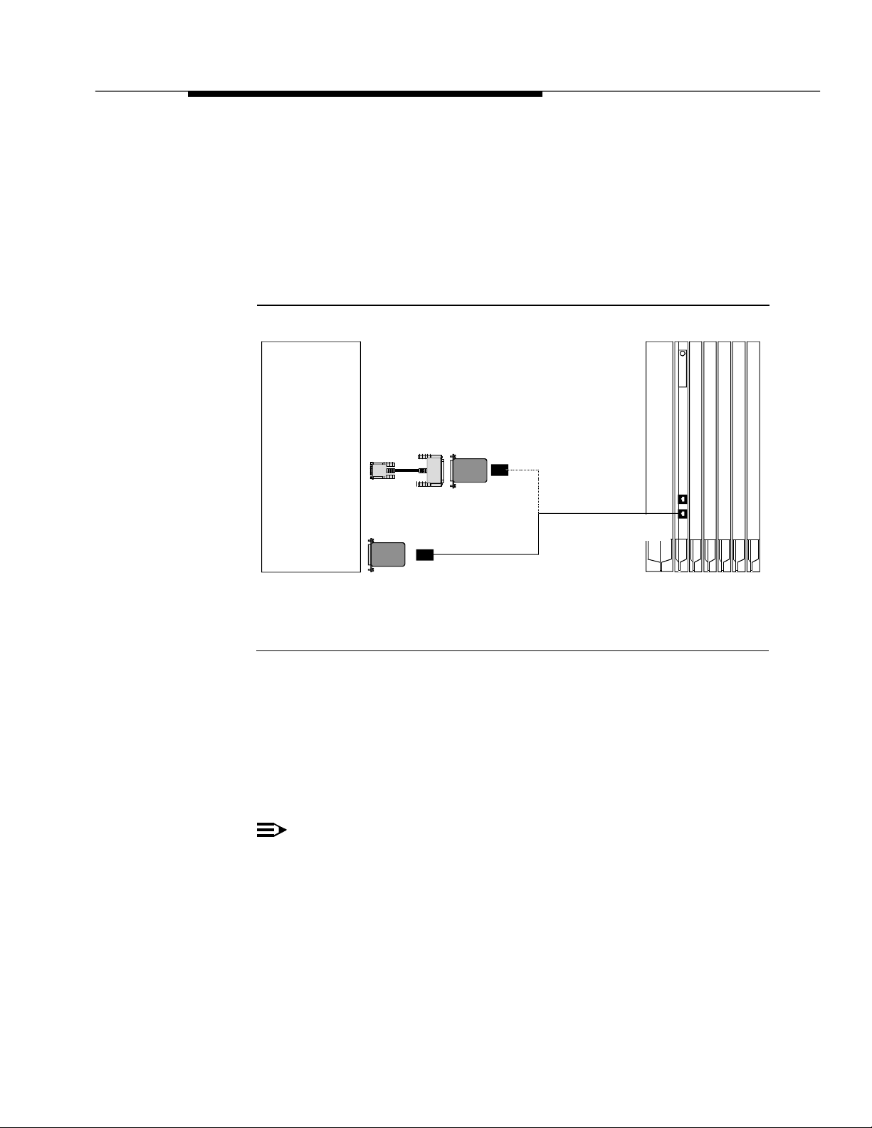
3. Connect to the Intuity system:
— For the MAP/5, connect the 355AF adapter directly to Serial Port 1
(tty00) of the MAP/5.
— For the MAP/4 0 an d MA P/100, connect the 355AF adapter to t he
25-pin end of the DB-9S to DB-25P adapter and then connect the 9pin end of that adapter to port COM1 (tty00) of the MAP/40 or
MAP/100.
Intuity
System
Processor
MAP/40
MAP/100
DB-9S to DB-25P
Adapter
COM1
Port
355AF
Adapter
MAP/5
Serial
Port 1
355AF
Adapter
Figure 4-3. Connecting Admin Ports Within 50 Feet
and Same Power Outlet
Connect Admin Ports
More Than 50 feet/Different Power Outlet
This method is used only when the MERLIN LEGEND Communications System
and the Intuity system are more than 50 feet apart or do not share the same
power outlet.
NOTE:
The ME RLIN LEGEND system does not support out of building operation of
the Intuity system.
OR
D8W-87
Modular Cord
Max 50 Feet
ADMIN
Port
MERLIN LEGEND
Communications System
The following parts are required:
■ DB -9S to DB-25P Adapter (MAP/40 and MAP/10 0 onl y)
■ 355A F Adapter
■ Three D8W-87 Modular Cords
Issue 2.0 December 1995 4-7
Page 70

■ M7-U 87 Crossover Cable
■ Two (2) Z3A2 ADUs
■ Two M8AJ-87 Ca b les
■ D8AM-87 Modular Crossover Cable
■ Two (2) 400B2 Adapters
■ Two (2) D6AP-87 Modular Cords
■ Two (2) 248B Adapters
■ Two (2) 2012D Power Transformers
NOTE:
The combi n a t ion of a Z3A2 ADU and a M8AJ-87 cable is equivalent to a
Z3A4 ADU. You must or d e r b oth p ieces (one of each).
NOTE:
Inside wire must b e 4-pair, suitable for data; type 3 UTP data cab le or
better.
Refer to Figure 4-4. Connect the MERLIN LEGEND Communications System
Admin port and the Intuity system Serial Port 1 (CO M1) b y following these step s :
1. Connect one end of a D8W-87 modular cord to the Admin (lower) modular
jack on the MERLIN LEGEND Communications System.
2. Connect the other end of the D8W-87 modular cord to a 3 5 5AF adap t er.
3. Connect the 355AF adap ter to one end of an M7-U87 crossover cable.
4. Connect the o the r end of th e M7-U87 crossover cabl e to th e matching end
of a M8AJ-87 c able.
5. Connect the o ther end of the M8AJ-87 cable to the matching connector on
a Z3A2 ADU.
6. Connect one end of a D8W-87 modular cord to the modular jack marked
WALL on the Z3A2 ADU.
7. Connect the other end of the D8W-87 modular cord to the modular jack
end of a D8AM-87 crossover cord.
8. Connect the modular plug end of the D8AM-87 crossover cord to the
matching modular jack on a 400B2 adapter.
9. Plug the 400B2 adapter into the wall jack leading to the Intuity system site.
10. Connect one end of a D6AP-87 modular cord to the 400B2 adapter.
11. Mount a 248B adapter to a 2012D power transformer.
12. Connect the other end of the D6AP-87 modular cord to the 248B adapter.
13. Plug the 201 2D p ower transf orme r into an AC p ower outle t.
4-8 Issue 2.0 December 1995
Page 71
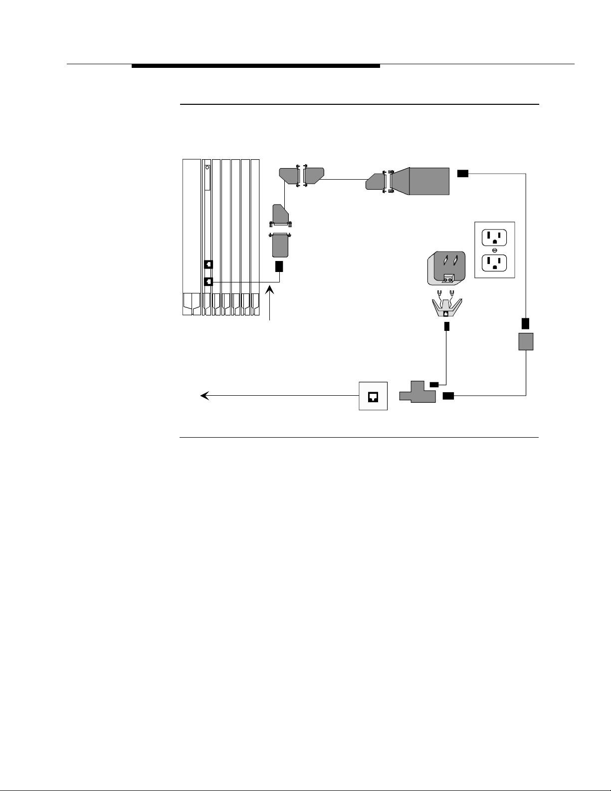
MERLIN LEGEND
Communications System
Processor
M7-U87
Crossover
Cable
355AF
Adapter
D8W-87 Modular Cord.
Maximum 50 Feet. Connect
to Admin (lower) Jack.
M8AJ-87
Z3A2-ADU
2012D
Power
Transformer
248B
Adapter
D8W-87
AC Power
Outlet
Wall Jack
Building Wiring to
Intuity System Site
Figure 4-4. Connecting Admin P orts More Than
50 Feet/Different Power Outlet
D6AP-87
400B2 Adapter
D8AM-87
Crossover
Issue 2.0 December 1995 4-9
Page 72
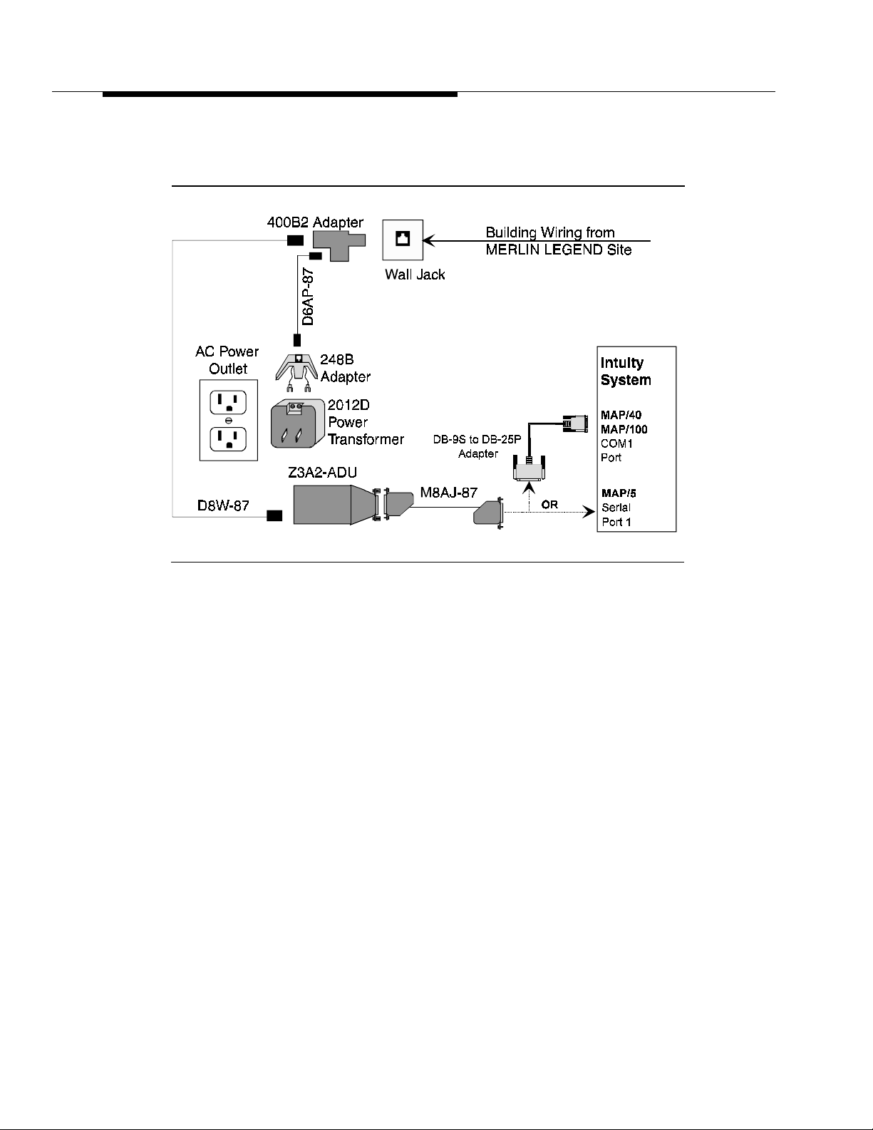
Go to the Intuity system site to cont inue th e c o nnection. Refer to Figure 4-5.
Figure 4-5. Connecting Admin P orts More Than
14. Connect to the Intuity system:
15. Connect the other end of the M8AJ-87 cab le to the Z3A 2 ADU.
16. Connect one end of a D8W-87 modular cord to the modular jack marked
WALL on the Z3A2 ADU.
17. Connect the other end of the D8W-87 modular cord to a 400 B 2 ad a p t er.
18. Plug the 400 B2 ad a p t er into the wall jack from the Comm unica tions
System site.
19. Connect one end of a D6AP-87 co r d to the 400B 2 a d a p t er.
50 Feet/Different Power Outlet
— For the MAP/5, connect one end of a M8AJ-87 cable direct ly to
Serial Port 1 (tty00) of the MAP/5.
— For the MAP/4 0 an d MA P/100, connect one end of a M8AJ-87
cable to the 25-p in end of the DB-9S to DB-25P adapter, and then
connect the 9-pin end of that adapter to port COM1 (tty00) of the
MAP/40 or MAP/100.
4-10 Issue 2.0 December 1995
Page 73

20. Mount a 248B adapter on a 2012D power transform er.
21. Connect the other end of the D6AP-87 cord to the 248B ada pter.
22. Plug the 201 2 D p ower transf orme r into an AC outlet .
Connecting SMDR Ports
Within 50 feet, Same Power Outlet
This method is used only when the MERLIN LEGEND Communications System
and the Intuity system are within 50 feet and share the same p ower outl et.
The following parts are required:
■ For connect ion to Serial Port 2 (MAP/5) or COM2 (MAP/40 an d MAP/100):
— DB-9 S to DB-25P Adap te r
— 355AF Ada p ter
— Z200A EMI Filter Modu lar Cord
■ For connection to first availab l e p ort on th e Mult i-Port Serial Card:
— Multi-Port Serial Card (if not already installed)
— 6 posit ion, 6 c onductor straight-through modular cord (supplied
with Multi-Port Serial Card)
— DTE 4/6-to-DB-25P Adapter (supplied with Multi-Port Serial Card)
NOTE:
This ad a pt er ha s slanted s id es as shown in the fig u re.
— 355AF Ada p ter
— Z200A EMI Filter Modu lar Cord
Connect to Serial Port 2 (COM2) if it is available and if it is not reserved for use by
a R emote Maintenance Modem. If Se rial Port 2 (COM2) is not available, connect
to the first available port on the Multi-Port Serial Card.
Connecting to Serial Po rt 2 (COM2 )
To connect to Serial Port 2 (COM2), refer to Figure 4-6. Connect the MERLIN
LEGEND Commu nications Syst em SMDR port and the Intuity syst em p ort b y
following these ste p s :
1. Connect the short end of the Z200A EMI Filter modular cord to the SMDR
(upper) jac k of the MERLIN LEGEND Communications System.
2. Connect the long end of the Z200A EMI Filter modular cord to a 355AF
adapter.
Issue 2.0 Dec e mber 1995 4-11
Page 74

3. Connect the 355AF adapter to the matching connector of a 9-pin-to-25-pin
adapter.
4. Connect the other end of the 9-pin-to-25-pin adapter to the Serial Port 2
(MAP/5) or COM2 (MAP/40 and MAP/100) of the Intui ty syst em .
Intuity
System
MAP/5
Serial
Port 2
MAP/40 &
MAP/100
COM2
DB-9S to
DB-25P
Adapter
Cable
355AF
Adapter
Long End
Z200A EMI Filter
Communications System
Max 50 Feet
Figure 4-6. Connecting SMDR Ports Within 50 Feet and
Same Power Outlet (Serial Port 2 or COM2)
Connecting to First Avai lab le Serial Port on
Multi-Port Serial Card
MERLIN LEGEND
Processor
Short
End
SMDR
Port
To connect to the first available port on th e Mult i-Port Serial Card, refer to Figure
4-7. Connect the MERLIN LEGEND Communications System SMDR port and the
Intuity system port by following these steps:
1. Connect the short end of the Z200A EMI Filter modular cord to the SMDR
(upper) jac k of the MERLIN LEGEND Communications System.
2. Connect the long end of the Z200A EMI Filter modular cord to a 355A
adapter.
3. Connect the 355A adapter to the 25-pin side of the DTE 4/6-to-DB 25P
adapter.
4. Connect one end of the 6-position, 6-conductor modular cord to the DTE
4/6-to-DB 25P adapter.
5. Connect the other end of the modular cord to the first available port on the
Multi-Port Serial Card.
4-12 Issue 2.0 December 1995
Page 75

Intuity
System
Multi-Port
Serial Ports
First Available
6P6C
Modular cord
Card
Port
DTE 4/6-toDB 25P
Adapter
355AF
Adapter
Figure 4-7. Connecting SMDR Ports Within 50 Feet and
Same Power Outlet (Multi-Port Serial Card)
Connecting SMDR Ports
More Than 50 feet/Different Power Outlet
Long End
Communications System
Short
Z200A EMI Filter
Max 50 Feet
MERLIN LEGEND
Processor
End
SMDR
Port
This method is used only when the MERLIN LEGEND Communications System
and the Intuity system are more than 50 feet apart or do not share the same
power outlet.
NOTE:
The ME RLIN LEGEND system does not support out of building operation of
the Intuity system.
The following parts are required for connection to Serial Port 2 or CO M2:
■ D B -9S to DB-25P Adapt e r (f o r connection to Serial Port 2 on M AP/5 or
COM2 on MAP/40 or MAP/100 only)
Issue 2.0 Dec e mber 1995 4-13
Page 76

The followin g parts are required for connection to the Multi-Port Serical Card:
NOTE:
NOTE:
■ Multi-Port Serial Card (if needed and not already installed)
■ 6 p osit ion, 6 c o n ductor straight-through modular cord (for connection to
Multi-Port Serial Card only, su p pl ied with Multi-Port Serial Card)
■ DTE 4/6-to-DB -25P Adapter (for connect ion to Multi-Port Serial Card only,
supplied with Multi-Port Serial Card)
This ad a pt er ha s slante d s i d es as shown in Figure 4-9.
The followin g parts are required for either ty p e of connection:
■ 355AF Adapter
■ Z200 A EMI Filter Mod u lar Cord
■ Two D8W-87 Modular Cords
■ M7-U87 Crossover Cable
■ Two Z3A2 ADUs
■ Two M8 AJ-87 Cab le
■ D8AM-87 Modular Crossover Cable
■ Two 400B2 A d a p te rs
■ Two D6 A P-87 M odular Cord s
■ Two 248B Adapters
■ Two 2012D Power Transformers
NOTE:
The combi n a t ion of a Z3A2 ADU and a M8AJ-87 cable is equivalent to a
Z3A4 ADU. You must or d e r b oth p ieces (one of each for Admin port,
another of each for SMDR port) .
Inside wire must b e 4-pair, suitable for data; type 3 UTP data cab le or
better.
Connect to Serial Port 2 (COM2) if it is available and if it is not reserved for use by
a R emote Maintenance Modem. If Serial Port 2 (COM2) is not available, connect
to the first available port on the Multi-Port Serial Card.
Refer to Figure 4-8. Connect the MERLIN LEGEND Communications System
SMDR port a n d the Intuity system by followin g these step s :
1. Connect the short end of the Z200A EMI filter mo d ular cord to the SMDR
(upper) modular jack on the MERLIN LEGEND Communications System.
2. Connect the long end of the D8W -87 modular cord to a 355AF adapter.
4-14 Issue 2.0 December 1995
Page 77

3. Connect the 355AF a dap ter to one end of an M7-U87 crossover cable.
4. Connect the o the r end of th e M7-U87 crossover cabl e to th e matching end
of a M8AJ-87 c able.
5. Connect the o ther end of the M8AJ-87 cable to the matching connector o n
a Z3A2 ADU.
6. Connect one end of a D8W-87 modular cord to the modular jack marked
WALL on the Z3A2 ADU.
7. Connect the other end of the D8W-87 modular cord to the modular jack
end of a D8AM-87 crossover cord.
8. Connect the modular plug end of the D8AM-87 crossover cord to the
matching modular jack on a 400B2 adapter.
9. Plug the 400B2 adapter into the wall jack leading to the Intuity system site.
10. Connect one end of a D6AP-87 modular cord to the 400B2 adapter.
11. Mount a 248B adapter to a 2012D power transformer.
12. Connect the other end of the D6AP-87 modular cord to the 248B adapter.
13. Plug the 201 2D p ower transf orme r into an AC p ower outle t.
Issue 2.0 Dec e mber 1995 4-15
Page 78

MERLIN LEGEND
Communications System
Processor
M7-U87
Crossover
Cable
355AF
Adapter
Z200A EMI Filter Cord.
Maximum 50 Feet. Connect
to SMDR (upper) Jack.
Short End Toward MERLIN.
Building Wiring to
Intuity System Site
M8AJ-87
Wall Jack
Z3A2-ADU
2012D
Power
Transformer
248B
Adapter
400B2 Adapter
AC Power
D6AP-87
D8W-87
Outlet
D8AM-87
Crossover
Figure 4-8. Connecting SMDR Ports M ore Than
50 Feet/Different Power Outlet
Go to the Intuity system site to cont inue th e c o nnection. Refer to Figure 4-9.
4-16 Issue 2.0 December 1995
Page 79

Figure 4-9. Connecting SMDR Ports More Than
14. Connect to the Intuity System:
15. Connect the other end of the M8AJ-87 cab le to the Z3A 2 ADU.
16. Connect one end of a D8W-87 modular cord to the modular jack marked
WALL on a Z3A2 ADU.
17. Connect the other end of the D8W-87 modular cord to a 400B2 adapter.
18. Plug the 400 B2 ad a p t er into the wall jack from the Comm unica tions
System site.
50 Feet/Different Power Outlet
— To connect to Serial Port 2 on the MAP/5 or COM2 on the MAP/40 or
MAP/100, connect the 9- pin end of the 9-pin-to-25-pin ad apter to
Serial Port 2 on the Intuity system . Then c o nnect one end of an
M8AJ-87 c able to the 25-pin en d of the 9-pin-to-25-pin ada pter.
— To connect to the first available port on th e Mult i-Port Serial Ca r d ,
connect one end of the 6-position, 6-conductor modular cord to the
port. Connect the other e n d of the modular cord to the DTE 4/6-toDB-25P Adapter. Then connect one end of an M8AJ-87 cable to the
other end of the DTE 4/6-to-DB-25P adap ter
Issue 2.0 Dec e mber 1995 4-17
Page 80

Networking
19. Connect one end of a D6AP-87 co r d to th e 400B 2 a d a p t er.
20. Mount a 248B adapter on a 2012D power transform er.
21. Connect the other end of the D6AP-87 cord to th e 248B a dapter.
22. Plug the 201 2 D p ower transf orme r into an AC outlet .
Networking is an
op t ional
application on Intuity systems connected to the
MERLIN LEGEND system. MERLIN LEGEND system supports Intuity low-spee d
digital networking and AMI S analog networking. High-speed digital networking is
not supported since the MERLIN LEGEND syst em does not support the DCP
protocol.
There are two methods f or configuring low-spe ed d igital networking with the
MERLIN LEGEND system:
■ If the MERLIN LEGEND system has DID lines, Intuity low-spe ed digital
networking is connected through th e MERLIN LEGEND switch.
■ If the MERLIN LEGEND system does not have DID lines, the connections
use Loop Star t (LS) lines from the Central Office (CO) a n d b ypass the
switch.
AMIS Analog Networking requires no special hardware for connectivity since it
uses the voice channels already assigned to voice services. (Traffic
configuration rules may necessitate the addition of voice channels to absorb the
load of AMIS networking.)
In order to support AMIS Analog Networking, the MERLIN LEGEND system must
be configured to send incoming calls on external lines directly to AUDIX. (Touchtone codes on the incoming calls identify the calls as AM IS networking and
cause proper call handling.) Many MERLIN LEGEND customers already do this
in order to support an automated attendant.
Connecting Low - Speeed D igi tal N etw ork ing
The followin g parts are required:
■ A CCX Bo ard (includes c able and breakout box)
■ Modem (Paradyne
power supply)
■ DB-25 M-M cable
4-18 Issue 2.0 December 1995
®
COMSPHER E® 3820, includes modular cord and
Page 81

Refer to Figure 4-10. Connect the Intuity low speed networking by following these
steps:
1. Connect one end of the ACCX cab l e t o the connector on the ACCX card.
2. Connect the other end of the ACCX cable to the matching connector on
the break-out b ox.
3. Connect one end of the DB-25 M-M cable to the connector marked
RS-232-CH1 (2, 3, or 4) on the break-o ut box.
4. Connect the other end of the DB-25 M-M cable to the matching connector
on the modem.
5. Connect one end of the modular cord to the jack marked DIAL on the
modem.
6. Depending on whether or not the MERLIN LE GEND system is eq u i p ped
with DID lines:
not
— If the system does
modular cord t o a RJ11C telephone jack wired to a Loop Start (LS)
line from the CO.
— If the system has DID lines, connect the other end of the modular
cord to a MERLIN LEGEND Tip/Ring port that has an assigned DID
number.
NOTE:
If building wire is used, it must be type 3 UTP or better. The distance
limitation is the sa m e as for a station.
have DID lines, connect the other end of the
7. Connect the power supply connector to the modem.
8. Plug in the power sup ply.
9. Turn on power for the modem.
Issue 2.0 Dec e mber 1995 4-19
Page 82
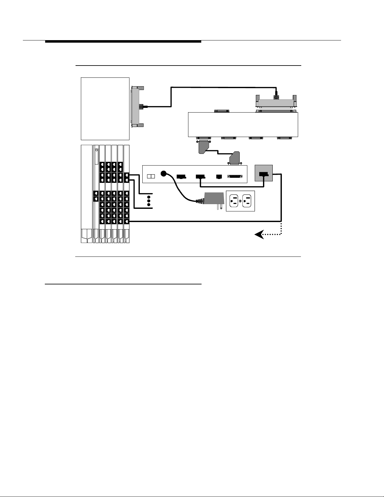
Intuity
System
ACCX
Card
ACCX Cable
RS232
Ch 1
DCP
RS232
Ch 2
Ch1 & 2
RS232
Ch 3
To ACCX
J1
RS232
Ch 4
Processor
Figure 4-10. Digital Networking Connections
Remote Maintenance
Remote Maintenance is an
system. While it is possible to use the “pass through” capability of the System
Programming and Maintenance Utility (SPM) for remote maintenance, this usually
requires operator assistance to do so. The Remote Maintenance op tion provides
simpler operation and a higher level of service.
Paradyne®
COMSPHERE 3820
Modem
01
PHONE DIAL
PWR
DID Lines
To Public
Network
MERLIN LEGEND
Communications System
optional
application for the MERLIN LEGEND Intuity
DB-25 M-M Cable
NAS DTE
With DID, To Tip/Ring Port
Without DID, To Public
Network L/S Line
Wall Jack
AC Power
Outlet
or
The Remote Ma inte nance Mode m must be connecte d to Serial Port 2 (COM2). If
Serial Port 2 (COM2) is already in use, you must do the following:
1. Move the device (if any) connected to Serial Port 2 (COM2) to the first
available p ort on the Multi-Port Serial Card. See de vic e sp ecific
instruct ions else where in this chapter.
2. Readminister the application formerly using Serial Port 2 (COM2) to use
the serial port now conne cted on the Multi-Port Serial Card.
3. Connect the Remote Maintenance Modem to Serial Port 2 (COM2).
4-20 Issue 2.0 December 1995
Page 83

The following parts are required:
■ DB -9S to DB-25P Ada pter
■ RS-232 M-F c abl e
■ Modem (Paradyne COMSPHERE 3820, includes modular cord and power
supply)
Refer to Figure 4-11. Connect the Intuity Remote Mai ntenance Modem by
following these ste p s :
1. Connect the small end of the DB-9S to DB-25P adapter to Serial Port 2 on
the MAP/5 or COM2 on the MAP/40 or MAP/100.
2. Connect the matching end of the DB-25 M-F cable to the large end of the
DB-9 S to DB-25P ad a p ter.
3. Connect the other end of the DB-25 M-F cable t o the matching connector
on the modem.
4. Connect one end of the modular cord supplie d wit h the m odem t o the jack
mar ked DIAL on the modem.
5. Depending on whether or not the MERLIN LE GEND system is eq u i p ped
with DID lines:
not
— If the system does
have DID lines, connect the other end of the
modular cord t o a RJ11C telephone jack wired to a Loop Start (LS)
line from the CO.
— If the system has DID lines, connect the other end of the modular
cord to a MERLIN LEGEND Tip/Ring port that has an assigned DID
number.
NOTE:
If building wire is used, it must be type 3 UTP or better. The distance
limitation is the sa m e as for a station.
6. Connect the power supply connector to the modem.
7. Plug in the power sup ply.
8. Turn on power for the modem.
Issue 2.0 Dec e mber 1995 4-21
Page 84
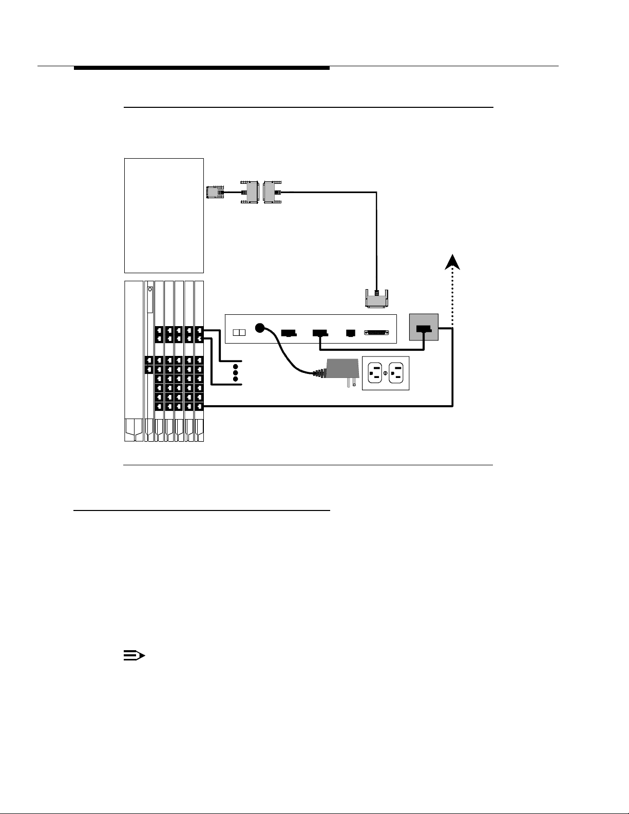
Intuity
System
MAP/5
Serial Port 2
MAP/40
MAP/100
COM2
Port
Processor
DB-9S-to-DB-25P
Adapter
Paradyne®
COMSPHERE 3820
Modem
01
PWR
PHONE
DB-25 M-F Cable
DIAL NAS DTE
Without DID,
To Public Network
L/S Line
Wall Jack
OR
Figure 4-11. Remote Maintenance Connections
Remote Access
Local Access to the Intuity system is p r o vide d by the keyboard and monitor of
the Intuity system. The Multi-User Feature Package and Remote Access is an
optional
convenient to have terminals located on the System Adm inist ra tor’s desk or at
other locations. While it is possible to use the “pass through” capability of the
MERLIN LEGEND system for remote access , t his usually requires operator
assistance. Remote administration allows system administrators to perform
dut ies at their desks, saving time and trips when the Intuity system is not cl o se
by.
DID Lines
To Public
Network
With DID, To Tip/Ring Port
AC Power
Outlet
MERLIN LEGEND
Communications System
application for the MERLIN LEGEND Intuity s yst em . It is som et im es
NOTE:
Only one user can be l ogg ed onto the Intuit y system at a time unle ss the
Multi-User Feature Package has been installed. With the Multi-User
Feature, the Intuity system can accommodate up to four simultaneous
logins.
4-22 Issue 2.0 December 1995
Page 85

Because the Multi-User Feature Package allows multi p le l o g in se ssio ns, it is
possible to delegate Intuity system administration d uties to several people. This
not only divides up the work neede d to maintain an Intuity system but also gives
subscribers and callers several points of contact should a problem occur.
Dedicated Lin e Acc es s
Dedicated line ac c ess can be used when a specific terminal will always b e
connected to t he line, that is, when dial-up access is no t required. Dedicate d l i n e
access is always to the first available port on the Multi-Port Serial Card.
Dedicated line ac c ess can be a ccomplishe d in the following ways:
■ If the termin al is withi n 50 feet of the Intui ty syst em , the termi nal can be
connected dire ctly t o th e Mu lti-Port Serial card using either of the methods
shown in Figure 4-12.
■ If the terminal is more than 50 feet from the Intuity system, it can be
connected to the Mu lti-Port Serial card usin g ADUs as line extenders.
In all other cases, re mot e access connections (using dial-up modems) should be
used.
Connecting Dedicated Lines w ithin 50 Feet
These methods are used only when the Intuity system and the terminal are within
50 feet.
The following parts are required:
■ Multi-Port Serial Card (if not already installed)
■ 6-position, 6-conductor straight-through modular cord (supplied with
Multi-Port Serial Card)
■ DCE 4/ 6-to-DB -25P Adapter
NOTE:
This ad a pt er ha s slanted s id es as shown in Figure 4-12.
■ DB-2 5 M-F cable
Refer to Figure 4-12. Connect the local terminal by fol lowin g these step s:
1. Connect one end of the 6-position, 6-conductor modular cord to the first
available p ort on the Multi-Port Serial Card.
2. Connect the other end of th e modular cord to the DTE 4/6-toDB-25P
adapter.
3. Connect the matching end of the DB-25 M-F cable to the DTE 4/6-to-DB25P a dapt er .
4. Connect the other end of the DB-25 M-F cable to the AT&T 715 terminal.
Issue 2.0 Dec e mber 1995 4-23
Page 86
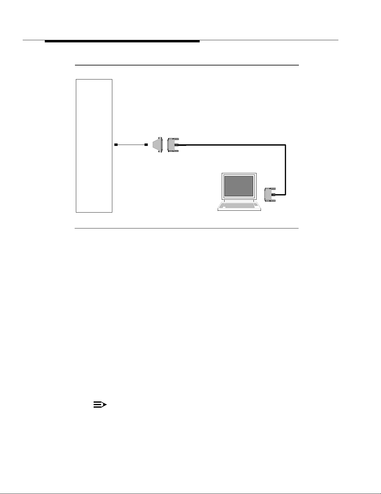
Intuity
System
DTE 4/6-to-DB-25P
Multi-Port
Serial Card
First Available
Port
6P6C Modular
Cord
Adapter
DB-25 M-F Cable
AT&T 715
Terminal
Figure 4-12. Local Dedica ted Line Term inal Connec tions
Connecting Dedicated Lines b eyond 50 Feet
This method is used only when the Intuity system and the terminal are more than
50 feet apart.
If the terminal is in a building outside the main building (where the In tui ty system
is located), an ADU and an additional protector must be installed in each
building. The ADUs and protectors provide both the Intuity system and the
terminal protection agai nst exposure to lightning, inadvertent contact with power
lines, and power currents induced by nearby power lines. See the installation
notes packed with the ADU for more information.
The followin g parts are required:
■ Multi-Port Serial Card (if needed and not already installed)
■ 6 p osit ion, 6 c o n ductor straight-through modular cord (for connection to
Multi-Port Serial Card only, su p pl ied with Multi-Port Serial Card)
■ DTE 4/6-to-DB -25P Adapter (for connect ion to Multi-Port Serial Card only,
supplied with Multi-Port Serial Card)
NOTE:
This ad a pt er ha s slante d s i d es as shown in Figure 4-13.
4-24 Issue 2.0 December 1995
Page 87

■ Two D8W-87 Modular Cords
■ M7-U87 Crossover Cable
■ Two Z3A2 ADUs
■ Two M8 AJ-87 Cab le
■ D8AM-87 Modular Crossover Cable
■ Two 400B2 A d a p te rs
■ Two D6 A P-87 M odular Cord s
■ Two 248B A d apter s
■ Two 2012D Power Transformers
NOTE:
The combi n a t ion of a Z3A2 ADU and a M8AJ-87 cable is equivalent to a
Z3A4 ADU. You must order both pieces (one of each for Admin port,
another of each for SMDR port) .
NOTE:
Inside wire must b e 4-pair, suitable for data; type 3 UTP data cable or
better.
NOTE:
Local powering of the Z3A2 ADU is optional.
Connect to the first available port on th e Mult i-Port Serial Card.
Refer to Figure 4-13 Connect the terminal and the Intuity system by fol lowing
these steps:
1. Connect one end of the M7U-87 crossover cable to the terminal.
2. Connect the other end of the M7U-87 cable to the matching end of a
M8AJ-87 c ab le.
3. Connect the o ther end of the M8AJ-87 cable to the matching connector o n
a Z3A2 ADU.
4. Connect one end of a D8W-87 modular cord to the modular jack marked
WALL on the Z3A2 ADU.
5. Connect the other end of the D8W-87 modular cord to the modular jack
end of a D8AM-87 crossover cord.
6. Connect the modular plug end of the D8AM-87 crossover cord to the
matching modular jack on a 400B2 adapter.
7. Plug the 400B2 adapter into the wall jack leading to the Intuity system site.
8. Connect one end of a D6AP-87 modular cord to the 400B2 adapter.
Issue 2.0 Dec e mber 1995 4-25
Page 88
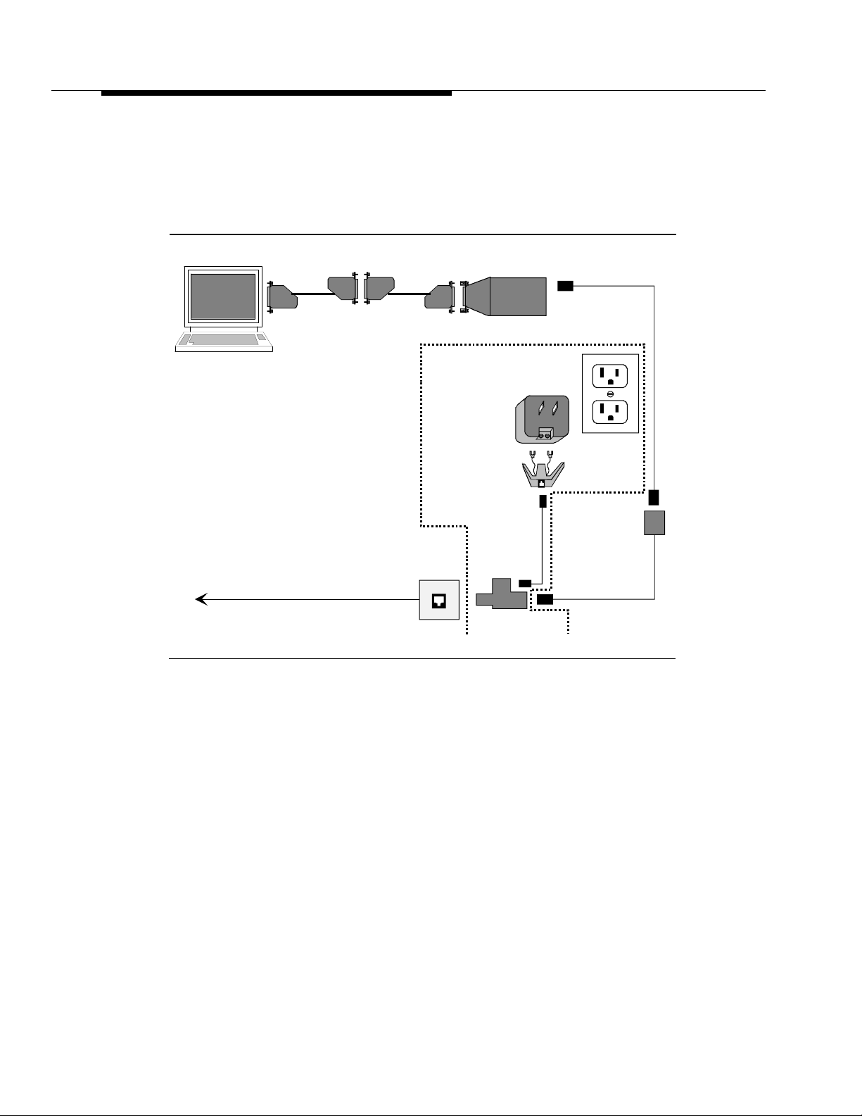
9. Mount a 248B adapter to a 2012D power transformer.
10. Connect the other end of the D6AP-87 modular cord to the 248B adapter.
11. Plug the 201 2D p ower transf orme r into an AC p ower outle t.
D8W-87
M7U-87
Crossover
M8AJ-87
Z3A2-ADU
AT&T 715
Optional Power
Terminal
2012D
Power
Transformer
248B
AC Power
Outlet
Adapter
D8AM-87
Wall Jack
D6AP-87
Crossover
Building Wiring to
Intuity System Site
Figure 4-13. Connecting Dedicated L ine Terminal More
Than 50 Feet (Terminal End)
Go to the Intuity system site to cont inue th e c o nnection. Refer to Figure 4-14.
400B2 Adapter
4-26 Issue 2.0 December 1995
Page 89

D8W-87
400B2 Adapter
Building Wiring to
Terminal Site
Wall Jack
Intuity
System
AC Power
Outlet
D6AP-87
Optional
Power
248B
Adapter
2012D
Power
Transformer
Multi-Port
Z3A2-ADU
M8AJ-87
6P6C Modular Cord
DTE 4/6-toDB 25P
Adapter
Serial Card
First Available
Port
Figure 4-14. Connecting Dedicated L ine Terminal More
Than 50 Feet (Intuity End)
12. Connect one end of the 6-position, 6-conductor modular cord to the first
available p ort on the Multi-Port Serial Card.
13. Connect the other end of th e modular cord to the DTE 4/6-to-DB-25P
Adapter
14. Connect one end of an M8AJ-87 cable to the DTE 4/6-to-DB-25P adapter.
15. Connect the other end of the M8AJ-87 cab le to the Z3A 2 ADU.
16. Connect one end of a D8W-87 modular cord to the modular jack marked
WALL on a Z3A2 ADU.
17. Connect the other end of the D8W-87 modular cord to a 400B2 adapter.
18. Plug the 400 B2 ad a p t er into the wall jack from the Comm unica tions
System site.
19. Connect one end of a D6AP-87 cord to the 400B2 adapter.
20. Mount a 248B adapter on a 2012D power transform er.
21. Connect the other end of the D6AP-87 cord to the 248B ada pter.
22. Plug the 201 2 D p ower transf orme r into an AC outlet .
Issue 2.0 Dec e mber 1995 4-27
Page 90

Remote Access (Dial- Up) Conn ec tio ns
Connect to Serial Port 2 (COM2) if it is available. If Serial Port 2 (COM2) is not
available, connect to the first available port on the Multi-Port Serial Card.
The followin g parts are required:
■ Multi-Port Serial Card (if needed and not already installed)
■ 6-position, 6-conductor straight-through modular cord (for connection to
Multi-Port Serial Card only, su p pl ied with Multi-Port Serial Card)
■ DTE 4/6-to-DB -25P Adapter (for connect ion to Multi-Port Serial Card only,
supplied with Multi-Port Serial Card)
NOTE:
This ad a pt er ha s slante d s i d es as shown in Figure 4-15.
■ DB-9S to DB-25P A dap ter (fo r connection to Serial Port 2 on M AP/5 or
COM2 on MAP/40 or MAP/100 only)
■ RS-232 M-F cable (for connection to Serial Port 2 on MAP/5 or to COM2 on
MAP/40 or MAP/100 only)
■ Modem (Paradyne COMSPHERE 3820, includes modular cord and power
supply)
Refer to Figure 4-15. Connect the Intui ty Remote Maintenance Modem by
following these ste p s :
1. To connect to the Intuity system:
— To connect to Serial Port 2 (COM2), c o nnect the small end of the
DB-9P to DB-25S adapter to Serial Port 2 on the MAP/5 or COM1 on
the MAP/40 or MAP/100. Then connect one end of the DB-25 M-F
cable to the large end of the DB-9P to DB-25S adapter.
— To connect to the first available port on th e Mult i-Port Serial Ca r d ,
connect one end of the 6-position, 6-conductor modular cord to the
port. Then connect the other end of the modular cord to the DTE
4/6-to-DB-25P a d apter.
2. Connect the other end of the DB-25 M- F cable or the DTE 4/6-to-DB-25P
adapter to th e matching connector on the modem.
3. Connect one end of the modular cord supplied with t he m odem to t he jack
mar ked DIAL on the modem.
4-28 Issue 2.0 December 1995
Page 91

4. Depending on whether or not the MERLIN LE GEND system is eq u i p ped
NOTE:
with DID lines:
not
— If the system does
have DID lines, connect the other end of the
modular cord t o a RJ11C telephone jack wired to a Loop Start (LS)
line from the CO.
— If the system has DID lines, connect the other end of the modular
cord to a MERLIN LEGEND Tip/Ring port that has an assigned DID
number.
If building wire is used, it must be type 3 UTP or better. The distance
limitation is the sa m e as for a station.
5. Connect the power supply connector to the modem.
6. Plug in the power sup ply.
7. Turn on power for the modem.
Intuity
System
MAP/5
Serial Port 2
MAP/40
MAP/100
COM2
Port
Multi-Port
Serial Card
First Available
Port
Processor
DB-9S-to-DB-25P
Adapter
6P6C Modular
Cord
Paradyne®
COMSPHERE 3820
Modem
01
PWR
DB-25 M-F Cable
DTE 4/6-toDB 25P
Adapter
PHONE
DIAL NAS DTE
Without DID,
To Public Network
L/S Line
OR
OR
DID Lines
To Public
Network
With DID, To Tip/Ring Port
MERLIN LEGEND
Communications System
Figure 4-15. Remote Access Dial-Up Connections
Issue 2.0 Dec e mber 1995 4-29
AC Power
Outlet
Page 92

MERLIN LEGEND Switch Administration
This chapter describes how to administer the MERLIN LEGEND system for
integration with the Intuity s ystem . Be sure to have the MERLIN LEGEND system
forms that you completed in Chapter 2.
5
Disconnect Signaling Reliability
Use this procedure to c lassify the d i sconnect signal sent b y the c e n tral office on
loop-star t trunks as reliable. The selected setti ng a p plies to all trunks in th e
system; trunks cannot be programmed individually. The disconnect signaling
reliability does not apply to ground-start trun ks emulat e d on a T1 faci lit y.
To set the disconnect signaling reliability:
1. From the System Programming menu, select Lines and Trunks.
■ On the c o nsole: Select LinesTrunks.
■ On th e PC: Press .
The Lines an d Trunks menu appears.
2. Select Touch-Tone/Loop St art Disconnect.
■ On the co nsole: Select TT/LS Disc.
■ On th e PC: Press .
The TouchTone/LS Disconnect menu appears.
3. Select Loop Start Disconnect.
■ On the c o nsole: Select LS Disconnect.
■ On th e PC: Press .
F4
F3
F2
The LS Reliable Disconnect menu appears.
Issue 2.0 December 1995 5-1
Page 93

4. Specify the disconnect signal as reliable.
■ On the c o nsole: Select Yes.
■ On th e PC: Press .
F1
5. Save your entry.
■ On the c o nsole: Select Enter.
■ On th e PC: Press .
F10
6. Return to the System Programmin g men u.
■ On the c o nsole: Select Exit two times.
■ On th e PC: Press two times.
F5
Group Coverage Member Assignments
Use this procedure to assign a telephone to a coverage group. Coverage is an
arrangement in which calls from a group of senders are redirected to one or
more receivers. A coverage group is a group of senders.
NOTE:
This procedure assigns senders.
A maximum of 30 coverage groups is allowed, each with an unlimited number of
mem b ers. U p to eig h t receivers can be assigned p er coverage group.
A telephone can be a s ender i n onl y one group; i t can be a receiver for more than
one coverage group.
To assign telephones to a coverage group :
1. From the System Programming menu, select Extensions.
■ On the c o nsole: Select Extensions.
■ On th e PC: Press .
F6
The Extensions menu ap pear s.
2. Access the second screen of the Extensions menu.
■ On the c onsole: Press More.
■ On th e PC: Press .
PgUp
3. Select Group Cover.
■ On the c o nsole: Select Group Cover.
■ On th e PC: Press .
F3
The Group Coverage screen app ears.
5-2 Issue 2.0 December 1995
Page 94

4. Enter the coverage group number (typically, 30.)
PgUp
5. Save your entry.
■ On the c o nsole: Select Enter.
■ On th e PC: Press .
F10
The Group Cover Senders sc reen ap pears.
6. Enter the extension number of the telephone yo u want to pu t in the
coverage group.
7. Save your entry.
■ On the c o nsole: Select Enter.
■ On th e PC: Press .
F10
8. Repeat Steps 6 and 7 for all extensions.
9. Return to the System Programmin g men u.
■ On the c o nsole: Select Exit two times.
■ On th e PC: Press two times.
F5
Group Calling Member Assignments
Use this procedure to assign an 012 module port to a calling group. A calling
group is used to direct calls to a group of people who all handle the same type of
call. A single extension number is assigned to the group and is used by both
inside and outside callers to reach the group.
A maximum of 32 calling groups with a maximum of 20 telephones per group is
allowed.
To assign a port to a calling group:
1. Select Extensions.
■ On the c o nsole: Select Extensions.
■ On th e PC: Press .
F6
The Extensions menu ap pear s.
2. Access the second screen of the Extensions menu.
■ On the c onsole: Press More.
■ On th e PC: Press .
3. Select Group Calling.
■ On the c o nsole: Select Grp Calling.
■ On th e PC: Press .
F4
The Group Calling menu appears.
Issue 2.0 December 1995 5-3
Page 95

4. Select Members.
■ On the c o nsole: Select Members.
■ On th e PC: Press .
5. Enter the extension number of the calling group. (Generally, use 770,
unless it has been renumbered.)
6. Save your e ntry.
■ On the c o nsole: Select Enter.
■ On th e PC: Press .
7. Enter the extension number of the port you want to assign.
8. Save your entry.
■ On the c o nsole: Select Enter.
■ On th e PC: Press .
9. Repeat Steps 7 and 8 for each extension.
10. Return to the System Programming menu.
■ On the c o nsole: Select Exit three times.
■ On th e PC: Press three times.
Group Calling Trunk or Pool Assignments
F9
F10
F10
F5
Use this procedure to assign or remove trunks or pools that rin g directly into a
calling group.
Incoming calls on each trunk or pool can b e directed to only one calling group.
To reassign a tr unk o r pool t o a new calling group, you mus t re move it from its old
group before making the new assignment.
To assign trunks or p ools to ring directly into a calling group:
1. From the System Programming menu, select Extensions.
■ On the c o nsole: Select Extensions.
■ On th e PC: Press .
The Extensions menu ap pear s.
2. Access the second screen of the Extensions menu.
■ On the c onsole: Press More.
■ On th e PC: Press .
5-4 Issue 2.0 December 1995
F6
PgUp
Page 96

3. Select Group Calling.
■ On the c o nsole: Select Grp Calling.
■ On th e PC: Press .
F4
The Group Calling menu appears.
4. Select Line/Pool.
■ On the c o nsole: Select Line/Pool.
■ On th e PC: Press .
F10
The Group Calling screen appears.
5. Enter the extension of the calling group (typically, 770).
6. Save your entry.
■ On the c o nsole: Select Enter.
■ On th e PC: Press .
F10
7. Enter the Line/Trun k num be r or pool number you want to assign.
NOTE:
If 801, 802, 803, etc. are in p ool 70, then you must s pecify 70.
8. Save your entry.
■ On the c o nsole: Select Enter.
■ On th e PC: Press .
F10
10. Return to the System Programming menu.
Hun t Type
Use this procedure to assign the hunt-type pattern to calling groups as linear.
When the linear hunting pattern is selected, the system searches for an available
group member in the order in which telephones were assigned to the calling
group.
To set the hunt-type patter n to linear:
9. Repeat Steps 7 and 8 as required for additional lines/pools.
■ On the c o nsole: Select Exit three times.
■ On th e PC: Press three times.
F5
1. From the System Programming menu, select the Extensions menu.
■ On the c o nsole: Select Extensions.
■ On th e PC: Press .
F6
The Extensions menu ap pear s.
Issue 2.0 December 1995 5-5
Page 97

2. Access the second screen of the Extensions menu.
■ On the c onsole: Press More.
■ On th e PC: Press .
PgUp
3. Select Group Calling.
■ On the c o nsole: Select Grp Calling.
■ On th e PC: Press .
F4
The Group Calling menu appears.
4. Select Hunt Type.
■ On the c o nsole: Select Hunt Type.
■ On th e PC: Press .
F1
The Group Calling screen appears.
5. Enter the extension number of the calling group.
6. Save your entry.
■ On the c o nsole: Select Enter.
■ On th e PC: Press .
F10
7. Specify the hunt pattern as linear.
■ On the c o nsole: Select Linear.
■ On th e PC: Press .
F2
8. To save your selection an d program the hunt type for another calling
group:
■ If the next group extension number is sequential:
— On the co nsole: Select Next and repeat Step 7.
— On the PC: Press an d repeat Step 7.
F9
Your previous entry is saved and the next gro u p exten sion
number is shown on line 1 of the screen.
■ If the next group extension number is not sequential:
— On the co nsole: Select Enter and repeat Steps 5-7.
— On the PC: Press a nd re p eat Ste ps 5-7.
F10
To save your selection when all entries are c omplete:
■ On the c o nsole: Select Enter.
■ On th e PC: Press .
F10
5-6 Issue 2.0 December 1995
Page 98

9. Return to the System Programmin g men u.
F3
■ On the c o nsole: Select Exit three times.
■ On th e PC: Press three times.
Group Coverage Receiver
Use this procedure to assign a calling group as receiver for a coverage group.
Calling group member assignments mu st b e ma d e b e f ore you ass ign the grou p
as a receiver for a coverage group.
To assign a calling group as receiver for a coverage group:
1. From the System Programming menu, select Extensions.
■ On the c o nsole: Select Extensions.
■ On th e PC: Press .
The Extensions menu ap pear s.
2. Access the second screen of the Extensions menu.
■ On the c onsole: Press More.
■ On th e PC: Press .
3. Select Group Calling.
■ On the c o nsole: Select Grp Calling.
F5
F6
PgUp
■ On th e PC: Press .
F4
The Group Calling menu appears.
4. Select Group Coverage.
■ On the c o nsole: Select GrpCoverage.
■ On th e PC: Press .
The Group Calling screen appears.
5. Enter the extension number of the calling group (typic ally, 770.)
6. Save your entry.
■ On the c o nsole: Select Enter.
■ On th e PC: Press .
F10
7. Enter the coverage group for which you want to assign the calling group
as receiver (typically, 30).
Issue 2.0 December 1995 5-7
Page 99

8. Save your e ntry.
■ On the c o nsole: Select Enter.
9. Return to the System Programmin g men u.
Group Type
This setting d et e rmines the type of voice messaging interface when the calling
group is used to connect voice messaging or automated attendant applications.
To set the group typ e:
1. From the System Programming menu, select Extensions.
2. Access the second screen of the Extensions menu.
■ On th e PC: Press .
■ On the c o nsole: Select Exit three times.
■ On th e PC: Press three times.
■ On the c o nsole: Select Extensions.
■ On th e PC: Press .
F10
F5
F6
The Extensions menu ap pear s.
■ On the c onsole: Press More.
■ On th e PC: Press .
PgUp
3. Select Group Calling.
■ On the c o nsole: Select Grp Calling.
■ On th e PC: Press .
F4
The Group Calling menu appears.
4. Access the second screen of the Group Calling menu.
■ On the co nsole: Press More.
■ On th e PC: Press .
PgUp
5. Select Group Type.
■ On the c o nsole: Select Group Type.
■ On th e PC: Press .
F1
6. Enter the extension number of the group.
7. Save your entry.
■ On the c o nsole: Select Enter.
■ On th e PC: Press .
F10
5-8 Issue 2.0 December 1995
Page 100

8. Select Integrated VMI. (For a dedicated IVR group, select Generic VMI.)
■ On the c o nsole: Select Integ VMI.
9. Save your entry.
10. Return to the System Programming menu.
Allowed Lists
Use this procedure to establish Allowed Lists, consisting of telephone numbers
that can be dialed from specified telephones, regardless of calling restrictions
assigned to telephones.
A maximum of eight lists, numbered 0 through 7, with a maximum of 10 numbers
each, numbered 0 th rough 9, is allowed, Each allowed number can be no more
than 6 digits (an area code plus an e xchange) or 6 digits with a leading 1, where
required.
If you program 0 as the first digit of a list entry, any toll restriction assigned to the
station is removed for calls that can be placed by a toll operator.
■ On th e PC: Press .
■ On the c o nsole: Select Enter.
■ On th e PC: Press .
■ On the c o nsole: Select Exit three times.
■ On th e PC: Press three times.
F3
F10
F5
Special characters (such as “pause”) are not permitted in Allowed List entries.
To establish Allowed Lists:
1. From the System Programming menu, select Tables.
■ On the c o nsole: Select Tables.
■ On th e PC: Press .
F8
The Tab les m enu appears.
2. Select Allowed List s.
■ On the c o nsole: Select AllowList.
■ On th e PC: Press .
F1
The Allowed List screen appears.
3. Enter the list (l = 0-7) and entry (e = 0-9) number. (If you are programming
a sequence, enter the lowest number.)
If you do not enter a list number, List 0 appears.
Issue 2.0 December 1995 5-9
 Loading...