

Page 1

555-230-894
Issue 1
September, 1995
Table of
Contents
DEFINITY® Communications
System
Generic 3 Installation
(For Single-Carrier Cabinets)
Graphics © AT&T 1988
Page 2

Blank Page
Page 3

Contents
Table of Contents i
About This Book xv
■ This Book’s Organization xv
■ Other Books xvi
■ Trademarks xvii
1 Overview and Roadmap 1-1
■ System Reliability 1-1
Standard R eliability 1-2
High Reliability 1-2
Critical Reliability 1-2
■ DEFINITY Syste m I nstal lati on Road m a p 1-3
Plan and Prepare the Site 1-3
Unpack the Cabinet s 1-3
Install and Connect the Cabinets 1-3
Install Telecommunications Cabling 1-4
Install Generic 3 Managemen t Terminal (G3-MT) 1-4
Activate the System 1-5
Test the System 1-5
Install and Wire Telephones an d Other
Equipment 1-6
Administer the D EFINIT Y System According to
Customer Requirements 1-7
Test Telephones and Other Equipment 1-7
2 Plan and Prep a re the Site 2-1
■ Check the Customer’s Order 2-1
■ Locate and Lay Out the Equi p me nt Room 2-2
Issue 1 Sept em ber 1995 iii
Page 4

Contents
Generic 3 Management Terminal
(G3-MT) Requirements 2-2
Cross-Connect Fields 2-2
Space Requirements 2-2
Room Layout 2-2
F igure Notes: 2-3
Cable Slack Manager (Optional) Requirements 2-4
Tools Need e d 2-4
Lay Out and Ensure Appropriate Power 2-6
Power Arrangements for AC Power 2-6
Power Arrangements for DC Power 2-7
■ Lay Out and Ensure Appropriate Grounding 2-8
Connect Coupled Bonding Conductor 2-8
■ Determine the Location of the Equ ipment Closets 2-9
■ Determine External Trunk Locations 2-9
■ Create a Provisioning Plan 2-9
3 Unpack the Cabinet 3-1
Unpack and Inspect for Damage 3-1
4 Install and Connect the Cabinet s 4-1
■ Install Earthq uake Mou ntin g 4-2
■ Position a nd Stac k t he Cabinets 4-2
■ Connect System Cabinet Grounds 4-3
F igure Notes: 4-4
■ Connect Battery Leads 4-5
■ Connect Power 4-6
Connect AC Power 4-6
Connect DC Power 4-6
F igure Notes: 4-8
Connect Power Plant Ground 4-9
F igure Notes: 4-9
Connect Frame Ground 4-10
Figure Notes: 4-10
Connect DC Power Distribution Box Grounding 4-11
iv Issue 1 September 1995
Page 5

Contents
Figure Notes: 4-11
Connect Single-Carrier Network Grounding 4-11
Figure Notes: 4-12
Coupled Bonding Conductor (CBC) 4-12
Figure Notes: 4-13
Connect DC Power to Networks 4-14
Connect AC Powe r to DC Power Cabinet 4-14
Test DC Power Plant 4-14
Connect Stand-by Power 4-14
■ Locate and Connect Time Division
Multiplexing (TDM) Bus 4-15
Figure Notes: 4-16
■ Locate and Connect Inter-Cabinet Cables (ICC) 4-17
Figure Notes: 4-18
■ Install Fibre-Optic Cables 4-19
Fibre-Optic Cable Operation 4-19
Locate Fibre-Optic Cable Connections 4-19
General Rules and Recommendations for
Connecting Fibre-Optic Cables 4-20
Figure Notes: 4-22
Figure Notes: 4-23
Raised Floor or Ca b le Slac k Managers 4-23
Cable Connections 4-24
Standard Reliability Fibre-Optic Cable Connections 4-25
High Reliability Fibre-Optic Cable Connections 4-26
Critical Reliability Fibre-Optic Cable Connections 4-27
■ Verify Port Cabinet Address Plug s 4-29
■ Install Back P anel s 4-30
■ Install Groun d Plates 4-30
Figure Notes: 4-30
Install Ground Plates on Systems with
Earthquake Protection 4-31
Install Ground Plates on Systems without
Earthquake Protection 4-31
Figure Notes: 4-31
■ Install Cable Clamp s 4-34
Figure Notes: 4-34
■ Install Front Plates 4-35
Issue 1 Sept em ber 1995 v
Page 6

Contents
Install Front Plates on Systems with
Earthquake Protectio n 4-35
Install Cabinet Clip On Systems without
Earthquake Protection 4-35
Figure Notes: 4-36
5 Install Telecommunications Cabling 5-1
■ Install the C ro ss-Connect Field 5-1
Typical Cross-Connect Field Using
110-Type Hardware 5-1
F igure Notes: 5-2
Hardware Installation 5-3
■ Install Cable Slack Managers 5-3
■ Route Cables from Cabinet to Cross-Connect Field 5-3
F igure Notes: 5-5
F igure Notes: 5-6
■ Connect Control Carrier Outputs Cable 5-6
Label Cables 5-7
■ Install Trunk Cables Among Network
Inter face, Sneak Current Protector, and
Switch Cabinet 5-7
6 Install Generic 3 Management Terminal 6-1
■ Generic 3 Management Terminal
(G3-MT) Requirements 6-1
■ Connect Generic 3 M anagement Term inal (G3-MT) 6-2
F igure Notes: 6-4
■ Set Up G3 Management Terminal (G3-MT) 6-6
■ Remotely Connect Generic 3
Management Terminal (G3-MT) 6-7
F igure Notes: 6-7
7 Activate the System 7-1
■ Power Up Switch 7-2
Install Translation Flash-Memory Card 7-2
vi Issue 1 September 1995
Page 7

Contents
Power up AC-Powered Switch 7-3
Power up DC-Powered Switch 7-3
Verify Messages on Terminal 7-3
■ Introduction to Terminal Screens and Com man d s 7-4
Screens 7-4
Commands 7-5
Getting Help 7-5
■ Log in to the System 7-5
■ Set Required Country Options 7-6
■ Change Craft Password 7-9
■ Set Date and Time 7-11
■ Set System Maintenance Parameters 7-14
■ Save Translations 7-15
Logoff 7-17
8 Test the Syste m 8-1
■ Check the System Status for Each Cab inet 8-1
■ Check Circuit Pack Configuration 8-4
■ Test Time Division Multiplexor (TDM)
Bus in Processor Port Network (PPN) 8-9
■ Test Tone -C lock Boards 8-10
■ Test Swit ch Processing Element (SPE)
Duplication Me mory Shadowing Link 8-11
■ Test Duplicated Switch Processing
Element (SPE) Interchange 8-12
■ Test Expansion Interface Boards 8-14
■ Test Time Division Multiplexer (TDM)
for each Expansion Port Network (EPN) 8-15
■ Test Tone-C lock for each Expansion
Port Network (EPN) 8-16
■ Test Tone-C lock Interchange for each
Expansion Port Network (EPN) 8-17
■ Test Expansion Interface Exchange for
Each Expansion Port Network (EPN) 8-17
■ Check Circuit Pack Configuration Again 8-19
■ Save Translations, if Required 8-20
Issue 1 Sept e m b er 1995 vii
Page 8

Contents
■ Re-install Front Doors 8-20
■ Next Steps 8-20
9 Install and Wire Telephones and
Other Equipment 9-1
■ Telephone Connection Example 9-1
Connect Adjunct Power 9-3
■ Analog Station or 2-Wire Digital Sta tion Example 9-5
■ Analog Tie Trunk Example 9-6
■ Digital Tie Trunk Examp le 9-9
■ Auxiliary Connector Output s 9-10
■ APP Connector and Cable Diagrams (Pinout Charts) 9-15
■ Install Init ialization and Administrat ion System (INA DS)
Interface 9-21
Figure Notes: 9-21
Figure Notes: 9-22
■ Install Emergency T ransfer Unit s and
Associated Telephones 9-23
Install the 808A Emergency Transfer Panel 9-23
■ Install External Ringing 9-24
Requirements 9-24
Installatio n 9-24
Figure Notes: 9-25
■ Install Queue Warning Indicator 9-25
Requirements 9-25
Installatio n 9-26
■ Install the 1145B 1 Power Sup ply 9-26
Wall-Mounting Plates 9-27
Figure Notes: 9-28
Mount the 1145B1 Power Supply 9-29
Figure Notes: 9-29
Mount the 1146B1 Power Distribution Unit 9-30
Battery Mounting / Wiring 9-30
Power Up and Test 9-31
Wire the 1146B1 Power Distribut ion Unit 9-32
viii Issue 1 September 1995
Page 9

Contents
Figure Notes: 9-32
Reset Light Emittin g Diodes (LED) on Power Distri b u t ion
Unit 9-33
■ Install the M SP-1 Power Sup pl y 9-34
Und erwriter’s Laboratories (UL ) Inform ation 9-34
Importan t Safety Instructions 9-35
Description of the MSP-1 Power Supply 9-36
Locate the MSP-1 Power S upply 9-36
Mount the MSP-1 Power Su pp l y 9-36
Connect the Power Supply 9-37
Figure Notes: 9-38
Figure Notes: 9-39
■ Install the Basic Rate Interface (BRI)
Terminating Resistor 9-39
Terminating Resistor Adapter 9-40
Closet Mounted (110RA1-12) 9-41
Figure Notes: 9-41
Figure Notes: 9-42
■ Install Mult i point Ada p te rs 9-42
BR851-B Adapter (T-Adapter) 9-43
367A Adapter 9-44
Basic Multipoint Installation Distances 9-45
Figure Notes: 9-46
■ Install Power Ad apters 9-47
400B2 9-47
400F2 9-48
■ Install Auxiliary Equipment 9-49
Auxiliary Equipment Description 9-49
Install Loudspeaker Paging and Music-on-Hold 9-50
Install Loudspeaker Paging Access without
Paging Adapter 9-50
Requirements 9-50
Figure Notes: 9-51
Install Loudspeaker Paging Access 9-51
Install Music-on-Hold Access 9-52
Requirements 9-52
Figure Notes: 9-53
Issue 1 September 199 5 ix
Page 10

Contents
Install Federal Communications Commission
(FCC) Registered Music Source 9-54
Install Re c o rded A nnoun c e m ent Equipment 9-54
Requirements 9-54
Figure Notes: 9-55
■ Install Proce s sor Dat a Modules (PDMs) 9-55
Requirements 9-55
Installation 9-56
Figure Notes: 9-57
Connection to Ind i vi dual Processor Data Modules
(PDMs) 9-57
Figure Notes: 9-58
■ Install Call Management Sys tem (CMS) Interface 9-58
Figure Notes: 9-59
■ Install Property Management Syste m (PMS) Interface 9-59
Requirements 9-59
Figure Notes: 9-61
■ Install Customer-Provided Terminal
Using Asynchronous Data Unit (ADU) 9-61
Requirements 9-61
Installatio n 9-61
■ Install Station Mes sag e Det ail
Recording (SMDR)/Call Detail
Recording Unit (CDRU) Interface 9-62
Interface Cabling to Station Message Detail
Recording (SMDR) Output Device 9-63
Figure Notes: 9-64
Switch Settings for Processor Data Module
(PDM), Trunk Data Module (TDM), or 21 2-Type
Mode m 9-65
212-Type Modem Switc h Setti ng 9-66
■ Imp l em e nt a nd Administer System Dat a 9-66
10 Test Telephones and Other Equip men t 10-1
■ Make Test Calls (Single-Cabinet Switch) 10-2
Description 10-2
Procedure 10-2
■ Make Test Calls (Two-Cabinet Switch ) 10-3
x Issue 1 Se p t em ber 1995
Page 11

Contents
Description 10-3
Proced ure 10-3
■ Make Test Calls (Thre e-Cabi net Switch) 10-4
Description 10-4
Proced ure 10-5
■ Test the Atten dant Console 10-8
Description 10-8
Procedure 10-8
■ Test the Selector Console 10-9
Description 10-9
Procedure 10-9
■ Test External Ringing 10-9
Description 10-9
Procedure—Ringing Device Installed 10-9
Procedure—Ringing Device Not Installed 10-10
■ Test Que u e Warning Indicator 10-10
Description 10-10
Procedure—Queue Warning Indicator Installed 10-10
Procedure—Queue Warning Indicator Not
Installed 10-11
■ Test Integrate d An nouncement 10-12
Description 10-12
Procedure — Record An n o uncemen t 10-12
Procedure — Playback Announcement 10-12
Procedure —Delete Ann ouncement 10-12
■ Test Music-on-Hold 10-13
Description 10-13
Procedure 10-13
■ Test Emergency Transfer 10-13
Description 10-13
Procedure 10-14
■ Test Remote Access Interface (know n
as Initializat ion a n d Administrat ion
System) 10-14
Description 10-14
Procedure—Remote Test 10-14
Issue 1 September 199 5 xi
Page 12

Contents
Procedure—Local Te st 10-15
■ Test Basic Rate Interface (BRI) 10-15
Description 10-15
Procedure—Dial Tone 10-15
Procedure—Make and Receive Calls 10-15
Procedure—Checking the Service Profile
Identifier (SPID) 10-16
A Approved Grounds A-1
■ Definition of Approved Ground A-1
■ Acceptable M ediums for Protective Ground A-1
■ Approved Floor Grounds A-2
B Earthquake Protection Procedures B-1
■ Install Floor Mountin g to Att ach Cabinet to Floor B-1
F igure Notes: B-2
F igure Notes: B-3
■ Install Groun d Plates on Cabinet Backs B-4
■ Install Front Plates B-4
C DEFINITY AUDIX System Power Procedures C-1
■ Manually Power Down DEFINITY AUDIX System C-1
■ Manual Power U p DEFINITY AUDI X System C-3
D Country Differences D-1
■ United States to Unite d King d om and
France Terminology Translations D-1
■ Country-Specific Ha rdware D-1
E Installing the 9400-Series Telephones E-1
■ Installi ng the 94 00-Seri es Telephones E-1
■ Wiring Information E-2
xii Issue 1 Sep tember 1995
Page 13

Contents
Distance Limitations E-4
F igure Notes: E- 5
F igure Notes: E- 5
■ Wall Mounting E-6
■ Using the Test Feature E-9
The Test Feat ure E-9
■ Button Labels E-10
F Wire Conversion Information F-1
■ Common Wire Colours F-1
■ AWG to SWG Conversion
(Stranded Wire) F-1
■ Wire Gauge Comparison
(S olid Conductor) F-4
G Electrical Code Equivalencies G-1
■ North American Electrical Code G-1
■ International Electrical Codes G-1
H Option Switch Settings H-1
■ Distributed Communications System
(DCS) Opti on Settings for G3i System s H-1
■ Mod em Pooling (Com bined) Option Settings H- 2
■ 103JR Modem Opti on Settings H-2
■ 201CR Modem Option Settings H-4
■ 202SR Modem Option Settings H-6
■ 208BR Modem O p ti on Settings H-9
■ Asynchronous 212AR Modem Option Settings H-11
■ Synchronous 212AR Modem Option Settings H-14
■ Asynchronous 2224A Modem Option Settings H-17
■ Synchronous 2224A Mo d em O p tion Settings H-18
■ 7400A Option Settin g s H-19
■ Printer Opt i o n Settings H-20
■ 475 Printer Connected to a G3 Management Terminal H-21
Issue 1 S e p t em ber 1995 xiii
Page 14

Contents
■ 475 Printe r U sed as Sys t e m Printer H-21
■ 475 or 476 Printer Used as Journal
Printer for Hospitality Feature H-21
■ 470 or 471 Printer Used as Journal
Printer for Hospitality Feature H-28
■ 572 Printer H-30
■ Station Message Detail Re c ording
(SMDR) Interface Option Settings H-34
■ Audio Information Excha nge (AUDIX)
Interface Option Settings for G3i Systems H-36
■ TN760 Tie Trunk Circuit Pack Op tion Settings H-37
■ TN464C, D, E, F Option Settings H-41
TN464C/D O p tion Setting s H-41
Figure Notes: H-42
TN464E/F Option Settings H-42
Figure Notes: H-44
I References I-1
■ Basic I-1
■ Call Center I-5
■ Networks I-6
■ App l icat ion Sp ecific I-7
ABB Abbreviations ABB-1
IN Index IN-1
xiv Issue 1 Septem b er 1995
Page 15

About This Book
This book supports DEFINIT Y® Communications Systems Generic 3 Version 3
and later. This book provides procedures and information for installing the
hardware and initially testing the DEFINITY Communications Sy s tem Generic 3,
Models G3i and G3s. The information in this b o o k a pplies to single-carrier
cabinet switches only.
DEFINITY is a registered trademark of AT &T. DEFINITY Communications System
Generic 3 is a bbreviated as G3.
This Book’s Organization
This book is organized into 10 chapters and 10 appendices. The procedures in
this book should b e read and followed sequentially.
■
Chapter 1, "Overview and Roadmap"
Provides an overview of system reliability options a nd a step-by-step
roadmap for installing and testing the system.
■
Chapter 2, "Plan and Prepare the Site"
Explains how to plan and prepare the site and includes typical floor plans.
■
Chapter 3, "Unpack the Cabinet"
Explains how to safely unpack the cabinets.
■
Chapter 4, "Install and Connect the Cabinets"
Explains how to install the cabinets, install the power, and connect the
cabinets together.
Issue 1 September 1995 xv
Page 16

About This Book
■
■
■
■
■
■
■
Chapter 5, "Install Telecommunications Cabling"
Explains how to install cabling between the sw itch and the cross-c onnect
field.
Chapter 6, "Install Generic 3 Management Terminal"
Explains how to install and bring up the Generic 3 Management Terminal.
Chapter 7, "A c tivat e the System"
Explains how to act ivat e and initialize the s ystem .
Chapter 8, "Test the Sy st em"
Explains how to test the system.
Chapter 9, " In stall a nd Wire Telephones and Other Equipment"
Explains how to install and wire telephones an d other equipment to the
switch.
Chapter 10, " Test Tel ephones and Other Equipment"
Explains how to test the e q u i p men t insta lled in Chapter 9.
App endix A, "Approved Grounds"
■
■
■
■ Appendix E, "Installing the 9400-Series Telephones"
■ Ap p e ndix F, "Wire Conversion Information"
■ Ap p endix G, "Electrical Code Equivalencies"
■ Appendix H, "Option Switch Settings"
■ Appendix I, "References"
■ Abbreviations
■ Index
Other Books
In add i t ion t o this book, other sy stem d escription, installation a n d test ,
maintenance, and administration books are available. A complete list of
DEFINITY Generic 3 books available in United States English can be found in the
Global Business Communications S ys tems Publications Catalog,
list of books relevant to this product can be found in Appendix I.
App e ndix B, "Earthquake Protection Procedures"
App e ndix C, "DEFINITY AUDIX System Power Procedures"
App e ndix D, "Country Diffe rences"
555-000-010. A
xvi Issue 1 Septem b er 1995
Page 17

Trademarks
This ca t alog and all DEFIN ITY Communications System Ge n eric 3
documentation in United States English can be ordered directly from:
General Business Communications System Publications Fulfillment Centre at
1-317-361-5353.
Trademarks
This book contains refe rences t o the following trademarked products:
■ AUDIX
■ DEFINIT Y
■ LINX
■ Shockwatch
■ Styrofoam
■ SYSTIMAX
■ Tiltwatch
®
is a registered trademark of AT&T
®
is a registered trademark of AT&T
™
is a trademark of Illinois Tool Works, Inc.
™
is a trademark of Me dia Recovery, Inc.
™
is a trademark of Styrofoam Corporation
®
is a registered trademark of AT&T
™
is a trademark of Media Recovery, Inc.
Issue 1 September 1995
xvii
Page 18

About This Book
xviii Issue 1 September 1995
Page 19

Overview and Roadmap
This chapter present s g eneral inform at ion about the methods to configure your
DEFINITY Syste m G e n eric 3 for system availability.
It also provides a roadma p (a high-level overview of the seq uence of steps) f o r
the installation of the system. The roadma p provides references to the
appropriate chapter in this book or other books for d etailed instruc tions.
1
System Reliability
The DEFINITY Syste m G 3 provides various system reliability configurations or
du plication options. These reliability configurati ons provide for dupli ca tion of G3
system co mponents for higher system availability. The f ollowi n g three types of
reliability suppl y your system’s needs:
■ Standard Reliability
■ High Reliability
■ Critical Reliability
Within these conf i g urat ion o ptions, you ca n d uplicate the following components:
■ Processor Port Network (PPN) Cont rol Carrier
■ Expansion Port Network (EPN) Control Carrier
■ Inter-Port Network (PN) Connectivity (fibre-optic cabling)
■ Tone-Clock
Chapter 4, "Install and Connect the Cabinets" provides more detail on system
reliability configurations.
Issue 1 S e p t em ber 1995 1-1
Page 20

Overview and Roadma p
Standa rd Reliab il ity
DEFINITY System G3 sta ndard reliabi lity systems p rovide the most co steffect ive product. This is the only reliability offering for a G3s system. Standard
reliability systems do not d uplicate Tone-Clock(s), the Control Carriers, or any
inter-Port Network (PN) co nnectivity.
Standard reliability systems use the fo llowi n g c o m ponents:
■ One control carrier per port network (Expansion Port Network (EPN) or
Processor Port Network (PPN))
■ One Tone-Clock per port network
■ Simplex inter-Port Network (PN) connectivity (via fibre-optic cables)
High Reliability
The G3i hi gh reliability option provides dup lication of hardware associated with
the Processor Port Network (PPN) Control Carrier.
High Reliabili ty systems use the following component s:
■ Duplicate Control Carriers in the Processor Port Network (PPN)
■ Duplicate Processor Port Network (PPN) Tone-Clocks, one in each
Control Carrier
■ One Tone-Clock per Expansion Port Network (EPN)
■ Simplex inter-Port Network (PN) connectivity
Critical Reliability
G3i critical reliability option provides the highest reliability through du p lication of
the control carrier(s), inter-Port Network (PN) connectivi ty, a n d Tone-Clocks.
Critical Reliability systems use the following comp onents:
■ Duplicate control carriers in the Processor Port Network (PPN) and
Expansion Port Network (EPN)
■ Duplicate Tone-Clocks in each port network (Processor Port Network
(PPN) and Expansion Port Network (EPN))
■ Duplicate inter-Port Network (PN) connectivity, using duplicated
Expansion Interface circuit packs and fibre optic c ables.
1-2 Issue 1 September 1995
Page 21

DEFINITY System Insta ll ation Road m ap
DEFINITY System Installation
Roadmap
This section is intended to provide a high-level sequence for th e instal lation
process and also a roadmap to the infor m ati on in thi s book. It is also noted
where specific steps are covered in othe r books.
Plan and Prepare the Site
Complete this task by following the instructions provided in Chapter 2.
1. Determine what was ordered for the customer: DEFINIT Y System
Generic 3, number of ca binets and port networks, management
terminals, adjuncts, consoles, telephones, modem s, external trunks, etc.
2. Locate DEFINITY System e quipment room and lay out equipment room
floorplan for system cabinet s, m anagement terminal and desk, crossconnect hardware and adjuncts, etc.
3. Lay out and ensure appropriate power for switch and management
terminal in equipment room and arrange for an electrician to install.
4. Lay out and ensure appropriate groundin g in equipment room (refe r to
App endix A, "Approved Grounds").
5. Determine location of e q uipmen t closets where large cables can be
connected out into smaller ones.
6. Determine where external trunk lines come into the building and where
external trunk converters and adapters will be inst alle d.
7. Determine an appropriate available port circuit on DEFINIT Y System for
each telephone, trunk, and peripheral connection needed and create a
provisioning p lan.
Unpack the Cabinets
Complete this task by following the instructions provided in Chapter 3.
1. Unpack and inspect the c abinets.
2. Check circuit packs.
Install and Con nec t the Cabin ets
Complete this task by following the instructions provided in Chapter 4.
1. Install earthquake floor mounting if needed (refer to Appendix A,
"Approved Grounds" ).
2. Posit i o n and stack cabinets.
3. Connect system cabinet grounds.
Issue 1 September 1995
1-3
Page 22

Overview and Roadma p
4. Connect battery leads.
5. Connect AC power
6. Locate and connect Time Division Multiplexer (TDM) Bus.
7. Locate and connect inter-cabinet cables, if system has duplicated Switch
Processor Elements (SPEs) in Processor Port Network (PPN) co ntrol
cabinets (high or critical reliability configurations).
8. Install fibre optic c ab les b e t ween port networks (if the syst em has mo re
than one cabinet stack).
9. Verify p ort ca binet a ddress p l u g s.
10. Replace cabinet back panels.
11. Install g round p l ates.
12. Install c a b le clamp s.
13. Install front plates (if needed for electromagnetic shielding and/or
earthquake protection
Procedures").
14. Install c a b inet clip (i f you do not have earthquake prote ct ion or
electromagnetic shielding).
or
DC power.
Install Telecom m un ication s Cab ling
Complete this task by following the instructions provided in Chapter 5.
— see Appendix B, "Earth quake Protection
1. Install cross connect equipment.
2. Install cab le slack manager.
3. Route cab les from cabinet to cross-connect field.
4. Connect control carrier ou tputs ca b le.
5. Label cables.
6. Install trunk cables among network interface, sneak fuse or circuit
breaker panel, and switch ca binet .
7. Install coupled bonding conductor grounding.
Install Gen eric 3 Management Terminal (G3-MT)
Complete this task by following the instructions provided in Chapter 6.
1. Connect Management Terminal.
2. S et up Management Terminal.
3. Connect remote Management Terminal (if included).
1-4 Issue 1 September 1995
Page 23

DEFINITY System Insta ll ation Road m ap
Activate the System
Complete this task by following the instructions provided in Chapter 7.
1. Powe r up swit c h.
2. Log in to the system.
3. Set required count ry op t ion s.
4. Change craft password.
5. Set date and time.
6. Set system maintenance parameters, if Packet Controller (TN778 Circuit
Pack) is included.
7. Save a nd b ack up translations.
Test the System
Complete this task by following the instructions provided in Chapter 8.
1. Check the system status for e ach cabinet.
2. Check circuit pack configuration.
3. Test Time Division Multiplexer (T DM) bus in Processor Port Network
(PPN).
4. Test Tone -Clock boards.
5. Test Switch Processor Element ( SPE) duplication memory shadowing link,
only for hig h an d crit ical reliability system s.
6. Test duplicated Switch Processor Element (SP E) interchange, only for
high and critical reliability systems.
7. Test expansion int erface b oards, if present.
8. Test Time Division Multiplexer (T DM) for each Expansion Port Network
(EPN) , if Expansion Port Networks (EPN) are present.
9. Test Tone-Clock for each Expansion Port Network (EPN), if Expansion
Port Networks (EPN) are present.
10. Test Tone-Clock interchange for each Expansion Port Network (EPN),
only for critical reliability systems with Expansion Port Networks (EPN)
present.
11. Test expansion int erface exchange for each Expans ion Port Network
(EPN) , if Expansion Port Networks (EPNs) are present.
12. Check circuit pack confi gurati on, again.
13. Save a nd back up translatio n s again, if required.
14. Re-install front doors on switch c abinets.
Issue 1 September 1995
1-5
Page 24

Overview and Roadma p
NOTE:
Install and Wire Telep hones an d Other Equipment
Complete this task by following the instructions provided in Chapter 9.
For easier reference, installation steps and test steps are grouped in
separate chapters. It may be better to install each hardware component,
administer it, and then test it before going on to install another component.
As an exampl e , install the Atten dant Console using the procedures in
Chapter 9, " Inst all a n d Wire Telephones an d Other Equipment", administer
it using the procedures in "Administer the DEFINITY System According to
Customer Requirements" on page 1-7, and test it using the procedures in
Chapter 10, "Test Telephones and Other Equipment".
1. Make and label wiring cross connections for this cu stomer, using
provisioning p lan a s d irected in Step 7 of Chapter 2, "Plan and Prepare
the Site" .
2. Install and label equipment.
3. Install the attendant c onsoles.
4. Install the telephones.
5. Install the trunks.
6. Install the interface for the remote management terminal (known as
INADS).
7. Install the emergency transf er units and associated telephones.
8. Install external ringing.
9. Install queue warning indicator.
10. Install auxiliary power.
11. Install Basic Rate Interface (BRI) telephone, Basic Rate Interface (BRI)
terminatin g resistor, multipoint a d apter, and power adapter.
12. Install auxilliary equipment
13. Install the Processor Data Module (PDM).
14. Install the Call Manage ment System (CMS) interf ace.
15. Install Property Management System (PMS).
16. Install any customer-provided terminals using Asynchronous Data Units
( ADUs).
17. Install Station Mes sag e Det ail Recording (SMDR)/Call Detail Recording
Unit (CDRU) interface.
1-6 Issue 1 September 1995
Page 25

DEFINITY System Insta ll ation Road m ap
Adminis ter the D EFIN I T Y Syst em Ac cord in g to
Customer Requi remen ts
After the hardware is installed and the system is activate d , the d ata for system
and telephone features must be a d m in istered, using the provisioning plan
created for this customer in Step 7 in Chapt er 2, "Plan an d Prepare the Site". All
steps for the administration of the system are provided in the United Ki ng d om
English bo o k,
555-230-655.
DEFIN ITY Co mmunicat ions System Generic 3 Im p lementation
Test Telephones and Other Equip ment
Complete this task by following the instructions provided in Chapter 10.
1. Make test calls (single-port-network switch).
2. Make test calls (two-port-network switch).
3. Make test calls (three-port-network switch).
4. Test the a tt e ndant console and selector console.
,
5. Test ex t ernal ringing .
6. Test queue warning indicator.
7. Test inte g rate d announcement.
8. Test m usic-on-hold .
9. Test emergency transfer.
10. Test r emote access interface (known as INADS).
11. Test Basic Rate Interface (BRI).
Issue 1 September 1995
1-7
Page 26

Overview and Roadma p
1-8 Issue 1 September 1995
Page 27

Plan and Prepare the Site
This chapter describes tasks required to plan, prepare, and p ro vision the site
de pe n ding upon which DEFINITY Syst e m G eneric 3 was ordered. Perform the
following:
■ Check the customer’s order.
2
■ Locate and lay out the equipment room.
■ Lay out and ensu re appropriate p ower.
■ Lay out and ensure appropriate groundin g.
■ Determine location of equipmen t closets.
■ Determine location of external trunk lines.
■ Create a provi sioning plan.
Check the Customer’s Order
Determine what was ordered for the customer: DEFINITY System Generic 3 , the
number of cabinets, p o rt netw or ks, management terminals, a d juncts, consoles,
telephones, modems, external trunks, etc.
NOTE:
One port net work is e q u ivalent to one single-carrier-cabinet stack.
Throughout this document, “cabinet” sometimes refers to one single-carr ier
cabinet an d some times refers to one
accor ding t o the context. An attempt has been made to use “single-carrier
cabinet (SCC)” to mean exactly that and to use the more general term,
“cabinet,” to mean a stack of one or more sin g l e-carrier c abinets or a port
network. A “system” is one or more single carrier cabinet stacks.
stac k
of single-carrier cabinets,
Issue 1 S e p t em ber 1995 2-1
Page 28

Plan and Prepare the Site
Locate and Lay Out the Equipment Room
Determine where the DEFINITY Syste m G eneric 3 equipment room is located ,
and then lay out the equipment room floor plan for DEFINITY System cabinets,
management terminal and desk, cross-connect hardware and adjuncts, etc.
Generic 3 Management Term inal
(G3-MT) Requirements
In general, the Management Terminal must be directly connected to the cabin et
with the shortest possible cable. For maintenance purposes, the terminal must
be located in the same equipment room as the cabinet, or in sight of the cabinet.
Power fo r t h e terminal must be obtained from a single-phase standard 120 Volt
60 Hz or 230 Volt 50 Hz AC receptacle in the equipment room.
Cross-Connect Fields
Recommended hardware is the wall-mounte d 110 SYSTIMAX premises
distribution equipment for structured cabling systems.
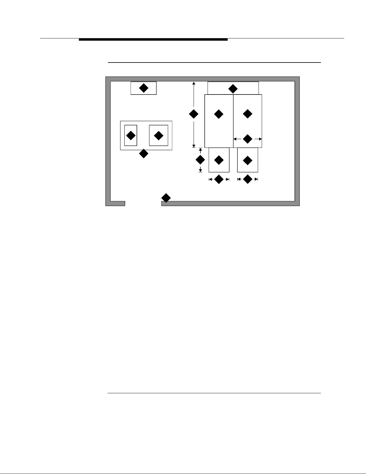
Space Requirements
The floor plan shown in Figure 2-1 p ro vides dimensions for the Processor Port
Network (PPN) cabinets and Cable Slack Managers.
Room Layout
Typical floor plans for a single-carrier cabinet are shown below:
2-2 Issue 1 September 1995
Page 29
Locate and Lay Out the Equip men t Room
4
1
5
3
2
Figure Notes:
1. Printer (Optional)
2. Wall
3. Table
4. Trunk/Auxiliary Field. May be Located
within Cross-Connect Field.
5. G3 Management Terminal (G3-MT)
6. Processor Port Network (PPN) Cabinets
7. Cable S lack Manager
14
8
7
11
6
12
8. Cross-Connect Field
9. Cable Slack Manager (Op tional)
10. Expansion Port Network ( EPN) Cabinets
(opti on al). S pace indica ted by callo uts 9
and 10 needed for e ach Expansion Port
Network (EPN) in system .
11. 22 Inches (55 cm)
12. 27 Inches (68 cm)
13. 32 Inches (81 cm)
14. 40 Inches (101 cm)
9
13
10
12
Additional Notes:
AC receptacles must be s ep ara te l y cu rre nt p rotecte d (fuse or circuit breaker) and n ot unde r the
cont rol of a wall switc h . Rec ep t acles must not be sh ar ed with othe r eq u ipment and s h ou ld be
located away from the cross-connect field.
System must be grounded by one of the approved methods. See Appendix A.
Earthquake protection and/or electromagnetic shielding may be required. See Appendix B.
Figure 2-1. Typical Floor Plan for G3i Single-Carrier Processor
Port Network (PPN) with Expan sion Port Network
(EPN) Cabinets
Issue 1 September 1995
2-3
Page 30

Plan and Prepare the Site
Cable Slack Manager (Optional) Requirements
A cable slack manager (optional) is 32 inches (81 c m) wide and 40 inches (102
cm) deep. Normally, one slack manager is needed for each cabinet stack. Extra
slack managers may be ordered, if necessary.
Tools Needed
Table 2-1 lists the tools and te st equip m ent required to install the switch. Make
sure all tools are available before inst alli n g th e DEFINITY System Generic 3.
2-4 Issue 1 September 1995
Page 31

Locate and Lay Out the Equip men t Room
Table 2-1. Tools and Tes t Equipm e n t In ventory
Recommended
Tasks Equipment Required
Unpacking
Cabinet
Installing
*
Cabinet
Checking
Com m e rcial Power
Circuit Pack
Voltage Check
Initia l izing S witch Generic 3 Management Te r mi na l 715 Management
Installing cables
and tele phon es
Ti n Snips
Utility Knife
Adjustable Wrench 6- or 8-inch
Electric Drill Impact type
Masonry Bit 1/2-inch
Drill Bit
(for Computer Floors only)
Drift Punch Length as required to
Cha lk Line
Rul e 30-inch
Adjustable Wrench 6- or 8-inch
Ratchet 1/2-inch 1/2-inch
Sockets 5/16-, 1/2-, and 3/4-
Nut d river 1/4-inch 1/4-in ch
Screwdriver 8-inch flat blade
All en Wr ench
Dig ital Multimeter KS-20599
Voltage Tester TN2036 (optional)
Diagonal cutters
Phillips screwdriver
Electric drill for install ing
information outlets
Impact tool for cross-connect
hardware
Test (telephone) set
‡
Type
5/8-inch
reach from computer
floor to concrete floor
inch
1/8-inch
Terminal
Recommended
Types for Europe
†
5/16-, 1/2-, and 3/4-
†
inch
†
* Electric drill and dril l bi ts are required for earthquake mounting.
† Since U.S./English fasteners are used, U.S. /English tools are required unless an exact match can
be found among metric tools.
‡ Required when installing an AC powered switch.
Issue 1 September 1995
2-5
Page 32

Plan and Prepare the Site
Lay Out and Ensure Appropriate Power
1. Lay out and ensure appropriate power for switch cabinets and
management terminal in equipment room.
2. Provide one power outlet per single-carrier cabinet.
3. Have an electrician check the commerci al power and verify p ower is
available and present.
Power Arrangements for AC Power
The fol lowing procedures appl y t o both the Processor Port Network (PPN)
cabinet(s) and Expansion Port Networks (EPN) cabinet(s) (as provided), except
where noted.
The fol lowin g illu strat ion sh ows a typical power and grounding layout, and the
illustration after tha t shows the AC p ower rec ep tacle req uirements. The power
circuit must be d e dicated to the DEFINITY System Generic 3 only and must be
on a separat ely current limited (fuse or circuit breaker) circuit. It must not be
shared with other equipment and must not be under th e control of a wall switch.
The power supply for the Generic 3 Management Terminal (G3-M T), however,
does not have to be dedicated
Locate and/or arrange the cross-connect field so all power receptacles are
accessible.
2-6 Issue 1 September 1995
Page 33

Locate and Lay Out the Equip men t Room
Power Arrangements for DC Power
The followin g table shows the i n p ut DC requirements for the system -48 VDC
Input Power Requirements
Parameter Requirements
Static Voltage -48 VDC nominal, -42.5 VDC minimum, -52.5 VDC maximum
(measured at inp ut to System cabinet) under normal
operating co nditions.
Dynamic
Voltage
AC Ripple
Voltage
Low Voltage
Disconnect
Overvoltag e
Protection
Voltage Drop Maximum drop—Must not exceed 0.5 V DC one way on
Current Draw The b attery p l a nt rectifiers must be capable of providing
Circuit Breaker An Underwriter Laboratories (UL) listed and Canadian
Redundancy Redundancy of the battery chargers/rectifiers should be
Transient change in volt age— +/- 5% of steady state
voltage . Al lowed tran sient d urati on— U p to 200
milliseconds.
Maximum wideband AC ripple — 4 50 mvpp (millivolts peakto-peak) in the 3 kHZ to 20 MHZ band.
Automatic disconnect—Occurs when input voltage is less
than -42.5 VDC (control provided with battery plant).
Input voltage at switching c abinets shall not exceed -52.5
VDC.
feeder cables between the power board and the System
cabinet. Feeders must be U n d erwriter L aboratories (UL)
approved (or e q uivalent) and Canadian Safety Association
(CSA) certified. Recommended -48 VDC feeder cable—
Royal Electric #X4905 or equivalent No. 1 AWG is required
for distances up to 50 feet (15 meters). Cab le resistance
must be equal to or less than 0.1290 ohms per 1000 f eet
304 meters).
current for the System including that required for System
holdover and for charging the batteries. In addition, this may
include DC curre nt required for an inverter that provides
Occupier to peripheral e qu ip ment if it is installed and for
future growth.
Safety Assoc iat ion (CSA ) ce rt ifie d ci rcuit breaker must be
provided at the battery plant power board for each System
cabinet feeder. The recom mended c ircuit breakers are 75
amp ere Airpax UPL-1-1REC2-52-753 or Heinemann AM1B2-A-75-2.
considered. This would also provide the ad di t iona l c u rrent
necessary to recharge the batteries after being fully
discharged.
Issue 1 September 1995
2-7
Page 34

Plan and Prepare the Site
Parameter Requirements
Electrical
Noise
Grounding A single point ground must be maintained. A ground
Lig htni ng
Protection
Voice band noise from the bat tery plant to the system must
be less than 32 dBrnC (decibels above reference noise wi th
C-filter or -58 dB mp (decibels below 1 milliwatt
psophometric).
conductor must be installed from the battery plant GROUND
DI SCH AR GE BAR to the closest “Approved Ground” via the
shortest and most direct route as required by the National
Electrical Code or applicable electrical co de in your area.
The gauge must be no smaller than the largest condu c tor in
the System an d larg er than 6 AWG. Ground i ng between the
system cabinet and th e b att ery p lant should be connected
using the procedures given later in this chapter.
There must b e adequate lightning prote ction in the b attery
plant to insure that the system will not be dama g e d .
Lay Out and Ensure Appropriate Grounding
Grounding is relat ively simple for an AC-powered switch. First, connect the
cabinets to each other. Then, c onnect a single ground wire from the Processor
Port Network (PPN) to th e approved prote ctive ground .
Grounding of the system must com ply with the general rules for grounding
contained in Article 250 of the National Electrical C o de (NEC), National Fire
Protection Agency (NFPA) 7 0 , or the appli cable electric code in your country.
See Appendix A for a description of “approved ground.”
Conne c t Cou pled Bonding Conductor
The Coupled Bonding Conductor connects to the single-point-ground-block and
runs adjacent to pairs in an associated telecommunications cable. The mutu a l
coupling between the bonding conductor and the pairs reduces potential
differences in terminating e q u i p me nt. The conductor consists of a 10 AWG wire
that must be tie-wrapped to the inside wiring ca b le and terminated at the
coupled bonding conductor terminal bar at the switch cross-connect field.
Refer to Ap p e ndix F for wire conversion information.
Refer to Figure 4-9 on page 4-13 for an illustration of a Coupled Bonding
Conductor.
If the approved protective ground or approved floor ground can only be
accessed inside a dedicated po wer equ ipment room, you should have an
electrician make the connections to this ground.
2-8 Issue 1 September 1995
Page 35

Determine the Location of the Equipment Closets
NOTE:
Check location of the AC power receptacle. The receptacle must be on a
separately current limited (fuse or circuit breaker) circuit not controlled by
a wall switch .
Determine the Location of the
Equipment Closets
Determine the location of the eq uipm ent closets where larg e cables can be
connected out into smaller ones. Determine locations of terminating resisters for
Basic Rate Interface (BRI) station circuits to be installed in equipment closets.
Determine External Trunk Locations
Determine where external trunk lines come into the building and be routed to the
equipment room. Determine where external trunk converters and adapters as
well as sneak-current fuse panels will be installed in the switch room (preferably
close or next to the cross connect fields).
Create a Provisioning Plan
Determine an appropriate available port circuit on the DEFINITY System for each
telephon e , trunk, and p eripheral connection needed, and, in addition, p lan for
auxiliary p ower for Basic Rate Interface (B RI) and certain d isplay sets.
Create a provisioning plan to include the following (see the example on the
following pag e):
■ Station or trunk type or feature/service.
■ Building loc ation (floor/room/desk/in form ation out let ).
■ Extension number or trunk group and member number.
■ Port c ircuit location on the switch for each endpoint (DEFINITY System
Generic 3 c a b inet /carrier/ slot/circuit.
■ Route from switch room through equ ip ment closets to each endpoint.
■ Auxiliary power supply, if re quired.
Issue 1 September 1995
2-9
Page 36

Plan and Prepare the Site
.
Table 2-2. Example of a Provisioning Plan
Building
Location
Extension
Number or
Trunk Group
and Member
Station or Tru nk
Type or
Feature/Service
8410
8403
Attendant Consol e
Analog CO
Digital Tie
.....
Music on Hold
(floor/room/
desk/
information
outlet
DEFINITY
G3 cabinet/
carrier/slot/
circuit
Route
from
equipment
closets
Auxiliary
Power
Required?
2-10 Issue 1 Sep t em ber 1995
Page 37

Unpack the Cabinet
This chapter describes the system unpacking procedures.
The DEFINITY Syst em Ge neric 3 (G3) single-carrier cabinet s are shipped in a
pol yethyle n e b a g , packed in a cardboard container. The cabinet is fastened to a
wood/Styrofoam p allet with two metal bands. The cardboard container is
strapped to the p a llet with anot her m etal b and.
3
!
DANGER:
Liftin g the cab inet requires two people, as it may wei g h as much as 130
pounds/60 kilograms. Use caution to avoid injury.
Unpack and Inspect for Damage
Unpacking the Cabinets
To unpack the cabinets, c o mplete the followi n g steps:
1. Check the status of the SHOCKW A TCH and / o r TILTWATCH i n dicators on
the ca rdbo ard c ont ainer. These indicators are white under normal
conditions. If the co ntai ner ha s b een shaken or tilte d beyond
specifications, the indicators will b e r e d , indicating potential damage.
Report any damage according to local shipping instructions.
2. Remove the cabinet from the c a rdboard container.
!
DANGER:
Take care to avoid injury while cutting and removing bands.
3. Remove all cardb oard, tape, and plastic.
September 1995 Issue 1 3-1
Page 38

Unpack the Cabinet
4. Op en an d rem o ve the front door a nd b ack panels from cabinet. The
screw location is shown in the following figures.
!
CAUTION:
Deep knife penetration may d ama g e the c a binet.
1
Figure Notes:
1. Screw tha t op e ns front cabinet doo r
Figure 3-1. Front Cabinet Door Latch Screw Location
Figure 3-2 shows the b ack panel screw locations.
3-2 Sep tember 1995 Issue 1
Page 39

1
1
2
3
Figure Notes:
1. Screws to remove
2. Screws to loosen
3. Screws to remain
22
1
2
3
1
Figure 3-2. Back Cabinet Panel Screw Locations
1. Remove all packing material from inside the cabinet.
Inspect Cabinet
2. Inspect cabinet for any damage that may have occurred during shipping.
Report any damages according to local shipping instructions.
Septem b er 1995 Issue 1 3-3
Page 40

Unpack the Cabinet
3. Verify the label near the circuit breaker on the power supply toward the
rear of each cabinet co rre spon d s to your local voltage type.
Check Circuit Packs
4. Ensure all c i rcuit p acks are fully inserted into the proper slots according
to the Customer Service Document (CSD). Report any discrepancies in
circuit pack type or quantity to your AT&T representative.
!
DANGER:
If the label i s d ifferen t than the volt age typ e at your site, notify your
A T & T representative immediately for a replacement power supply.
Do not, under any circumstances, connect the system to p ower!
3-4 Sep tember 1995 Issue 1
Page 41

Install and Connect the Cabinets
This chapter describes how to install the Processor Port Network (PPN) and
Expansion Port Network (EPN) single-carrier cabinets for DEFINITY System
Generic 3. Directions are provided for the following c onfigurat ions:
■ Standard reliability
4
■ High reliability
■ Critical reliability
Refer to About This B ook for a description of each configuration.
This chapter discusses single-carrier cabinets only. For information on multiple-
carrier cabinets, refer to the
Generic 3 Installation a n d Test
To install the ca b inet s, c omp l ete the fol lowing steps as detailed in this chapter:
1. Install earthquake floor mounting (if earthquake protection is required)
2. Posit i o n and stack cabinets
3. Connect grounds and Connect AC power or DC power
4. Connect Time Division Multiplexing (TDM) cables
5. Connect inter-cabinet cables (ICC)
6. Verify address plug settings
7. Install b ack plates
8. Install g ro und pl ates
9. Install front cabinet clips or ground plates
10. Connect fibre-optic cables
DEFINITY Communica t ions System Generi c 1 a nd
document.
11. Install d oors
Issue 1 S e p t em ber 1995 4-1
Page 42

Install an d Connect the Cabinets
Install Earthquake Mounting
If earthquake protection i s re q uired for your area, install earthquake floor
mountin g a s d irecte d in Appendix B.
Position and Stack the Cabinets
Follow the diagram in the Customer Service Document (CSD) shipped with each
cabinet, and stack the DEFINITY System G eneric 3 cabinets using these steps:
1. Place the control ca b inet in p ositi on at the locat ion de t ermined when
room layout was planned.
NOTE:
Check location of the AC/DC p ower recep t acle. The receptacle
must be on a se p arat ely f used circuit
switch. It must be located within 10 feet (3 meters) of the c a binet,
and shoul d b e l o c ated outside the cross-connect field area.
2. Stack the single-carrier cabinets by letter, according to the serial
numbers and lettered designation strips in the Customer Service
Document ( CSD), and as shown in Figure 4-1.
not
controlled by a wall
D
C
B
A
Figure 4-1. Cabinets Stacked by Letter
3. Remove the front cabinet door and back cabinet panel. See " Unpack and
Inspect for Damage" on page 3-1 for more information.
4-2 Issue 1 September 1995
Page 43

Connect System Cabinet Grounds
Connect System Cabinet Grounds
To connect ground, refer to Figure 4-2 on page 4-4 and perf orm the foll owing:
1. At lower left rear of the P rocessor P ort Network (PPN) cabinet (Control
Cabinet A), connect a 6 AWG ground wire to the cabinet ground block.
See Appendix F for in ternational wire conversions for outside North
America.
NOTE:
A screwdriver is required to loosen and tighten the screws securing
the ground wire to the ground bloc k.
2. Run the ground wire to an ap p roved ground . Refer to Appendix A.
3. At the Expansion Port Netwo rk (EPN) cabinet(s) (as provided), connect a
6 AWG ground wire t o the A-c abinet ground block.
4. Run the ground wire from the Expansion Port Netwo rk (EPN) to the
Processor Port Network (PPN) cabinet and connect it to the cab inet
ground block.
NOTE:
If the Expansion Port Network (EPN) cabinet is remotely located
from the Processor Port Network (PPN) ca b inet (in a separate room
or building), run the 6 AWG cabinet ground wire to an ap proved
protective ground.
5. At the Processor Port Net work (PPN) cabinet, connect a 10-AWG wire t o
the cabinet ground block. At a later time, tie-wrap the ground wire
(coupled bonding conductor) to the trunk cables, termin ati n g it at the
coupled bonding conductor terminal bar at t he cross-connect field for the
switch. Refer to Figure 4-9 on pa g e 4-1 3 for an illustratio n of the c o u pled
bonding conductor.
Issue 1 September 1995
4-3
Page 44

Install an d Connect the Cabinets
3
2
1 1
ON ON
OFF OFF
7 7
12
13
ON ON
OFF OFF
4
ON ON
OFF OFF
12
9
5
ON ON
OFF OFF
11
6
7
7
8
10
Figure Notes:
1. Expansio n Port Network (EPN) Contro l
Cabinet A
2. Circuit breaker
3. Power sup p l y
4. Power receptacle in powe r su p p l y
5. Processor Port Network (PPN) Control
Cabinet A
6. Cabinet-stack single-point ground block
7. Power cord 2.5 meters
Figure 4-2. Typical AC Power and Groundin g Arrangement
for Single-Carrier Cabinet (Rear View)
8. National Electrical Manufacturer’s
Ass o ciation (NEMA) 5- 1 5 o r Na tional
Electrical Manufacturer’s Association
(NEMA)5-20 recep tacle or equivalen t
locally provided receptacles
9 . 6 AWG ground wire to approved ground
10. Generic 3 Management Terminal (G3-MT)
11. 1 0 AWG C oupled Bondi ng Con ductor
12. 6 AWG cabinet-stack ground conductor
13. Port cabinet
4-4 Issue 1 September 1995
Page 45

Connect Battery Leads
Connect Battery L eads
To prevent the batteries from discharging, the co n trol ca b inet is shipped with
the battery lead di sc onnect ed. To connect the batteries, perform the following:
At cabinet(s):
1. Ensure the c ircuit b reakers on ea c h c a binet are OFF.
Each ca b inet has its own power supply and the circuit breaker is located
on the rear of each power supply. See Figure 4-3.
2. Connect the battery lead:
See Fig ure 4-3. The ba ttery is near the top of the carrier toward the fro nt-
right. The battery leads should be immediately next to the ba t tery, on the
left side, and accessible from the front of the cabinet.
1
Figure Notes:
1. Battery
2. Circuit Breaker
3. Ground block
Figure 4-3. S ingle Carr i er Cabinet Control Cabinet
Battery Location, Right Side View
2
3
Issue 1 September 1995
4-5
Page 46

Install an d Connect the Cabinets
Connect Power
Connect either AC or DC power as described in this section.
Verify the label near the circuit breaker on the power supply toward the rear of
each ca b inet c orrespon ds to your local voltage type.
!
DANGER:
If the label is different than the voltage type at your site, notify your A T & T
representative immediately f o r a replacement power supply . D o not, under
any circumstances, connect to power!
Connect AC Power
Figure 4-2 applies to multiple Processor Port Networks (PPN) and Expansion
Port Network (EPN) c abinet arrang e m ent s. If mul ti p le Exp ansion Port Network
(EPN) c abinets are required, you must provide the recept acles f or the 4-cabinet
Processor Port Network (PPN) arrangement in addition to the receptacles for a
2-, 3-, or 4-cabinet Ex pansion Port Network (EPN) arrangem ent. Provide one
receptacle per single-carrier cabinet.
1. Verify the circuit breakers are OFF .
2. Connect cabinet AC line cords to the AC power rece pt acles. The AC line
cords for the cabinets must first be connected to the cabinets and then to
the AC power receptacles.
Conne c t DC Po wer
The fol lowing procedures appl y t o both the Processor Port Networks (PPN) and
Expansion Port Networks (EPN).
Figure 4-4 shows a typical power and groundi ng layout for a D C -powered
single-carrier cabinet. The size of the wire required for the -48 VDC and -48 volt
return must ensure the -48 VDC supplied by the battery plant to the cabinets will
be m aint ained between -42.5 and -5 2.5 volt DC. This ensures proper operation
and prevents hardware damag e.
4-6 Issue 1 September 1995
Page 47

Connect Power
GRD
15
2
1
5
-48V
-48VRTN
16
1
GRD
15
2
1
-48V
-48VRTN
16
1
GRD
15
2
1
-48V
-48VRTN
16
1
GRD
15
1
2
-48V
-48VRTN
17
5
1
1
1
1
6
3
4
7
-48V
RTN
1
9
12
1
7
10
(-48VRTN & GRD)
GRD
1
-48V
-48V
18
75A
75A
1
-48V
8
11
GRD
13
GRD
-48V
-48VRTN
11
7
14
Issue 1 September 1995
4-7
Page 48

Install an d Connect the Cabinets
Figure Notes:
1. Ground plat e (three required)
2. 3 Conductor No. 10 line co r d (on e per
cabinet)
3. Plug (male)
4. J58890CG DC Distribution Unit
5. Receptacle (female)
6. Cabinet single-point ground block
7. 6 AWG wire
8. 25 Amp Fuse (4 re q uir e d )
9. Coupled bond i n g co n duc tor to te rmi na l
bar at cross-connect field
10. Groun d discharge bar
11. 1 AWG wire
12. Ap p rove d grou n d
13. To cabine t singl e -p oint groun d b loc k in next
port cabinet
14. To DC distrib ution unit for next port network
15. 676B DC Power Supply
16. Port Cabinet
17. Control Cabinet
18. Ba ttery Plant
Figure 4-4. Typical Single-Carrier Cabinet System Direct
Current (DC) P ower and Grounding Wiring
!
CAUTION:
Grounding of the system shall comply with the g eneral rules for grounding
contained in Article 250 of the National E lectrical Code (NEC), National F ire
Protection Agency (NFPA) 7 0 , or th e applicable code in your area. See
App e ndix G for more information.
Determine the approved ground in the building to be wired. See A ppendix A.
Connect your system to an approved ground as described below.
4-8 Issue 1 September 1995
Page 49

Connect Power
1. 1 AWG wire
2. App roved gr ound. Must be conne c ted
to an approved ground using the correct
ga uge c able, te rminated with a listed
clam p, and identifi ed with an AT&T
gro un d tag or e quivalent.
3. DC Power Cabinet
4. Ground discharg e bar
Figure Notes:
Connect Power Plant Ground
To connect the power plant ground, complete the following steps:
1. At the DC power cabinet, connect a 1 AWG ground wire to the GROUND
DISC HARGE bar.
2. Route the ground wire out of the cabinet and terminate it on the approved
ground (see Figure 4-5). The ap proved ground must be identifie d with a
grounding tag (AT&T FORM 15657NR, or equivalent).
1
4
2
Figure 4-5. Power Plant Groundin g
3
Issue 1 September 1995
4-9
Page 50

Install an d Connect the Cabinets
Connect Frame Ground
Connect the 6 AW G frame ground cable to the cabinet frame b y following these
steps:
1. Measure and cut a length of 6 AWG cable. Use the p rovided cable or
measure and cut a length of 6 AWG cable long enough to reach between
the GROUND CONNECTION terminal in the DC Battery Cabinet and the
G ROUND DISCHARGE b a r in the DC Power Cabinet.
2. Crimp terminal lugs on each end of the wire. Terminal lugs are furnished
as part of D-181895, Kit of Parts.
3. At DC power cabinet, connect wire to the GROUND DISCHARGE bar.
4. Route the wire through one of the holes in the side of the ca b inet an d
terminate it on the GROUND CONNECTION te r min al i n the DC Ba ttery
Cabinet (see Figure 4-6).
4
Figure Notes:
1. 6 AWG wire
2. Ground discharg e bar
3. DC battery cabinet
1
3
4. Groun d c onne ct ion terminal
5. Power distribution unit
5
2
Figure 4-6. Frame Ground Groun ding
4-10 Issue 1 Sep t em ber 1995
Page 51

Connect Power
Connect DC Pow er Distribution Box Groundi ng
Run the 6 AWG ground c a ble from the DC Power Cabinet to each DC Power
Distribu t ion Unit , using the following steps:
1. At the DC Power Cab inet , c o n nect 6 AWG wire to the GROUND
DISCHARGE bar. Route the cable to the DC Power Distribu t ion Uni t.
Connect the cable to t he GRD Terminal Block in t he DC Power
Distribu tion Unit (see Figure 4-6).
2. Repeat Step 1 for each remaining DC Power Distribution Unit.
4
3
Figure Notes:
1. 6 AWG wire
2. To additional J588 90CG as p rovi ded
3. DC power cabi net
1
2
4. Ground discharg e bar
5. Power distribution unit
6. Ground terminal strip
6
5
Figure 4-7. DC Power Distribution Unit Groundin g (J58890CG)
Connect Single-Carrier Network Grounding
Each port cabinet must have a 6 AWG ground cable connected fro m t he ground
blo c k o f C ontrol C a b inet A to the DC Power Cabinet.
Use the following instru ctions to connect each network ground:
Issue 1 Septemb er 1995
4-11
Page 52

Install an d Connect the Cabinets
1. At the DC Power Cab inet , c o n nect a 6 AWG cable to the GROUND
DISCHARGE bar. Route the cable to the port Cabinet Carrier A. Connect
the cable to the single-point ground block in the Control Carrier (see
Figure 4-7).
2. Repeat Step 1 for each port Cabinet Carrier A in the system.
6
7
1
8
9
2
5
Figure Notes:
1. 6 AWG wire
2. Ground plate
3. C abinet stack single point g round bl ock
4. To additional Port Cabinet as provided
5. DC Power Cabinet
Figure 4-8. Ground Connection for Single-Carrier Network
Coupled Bonding Conductor (CBC)
The coupled bonding conductor (CBC) connects the cabinet single-point
ground block to the approved protective ground located nearest the (telephone
company owned) protector block at the building entrance facility. Fol low the se
steps to connect the coupled bonding conductor:
10
3
4
6. Ground discharg e bar
7. Port Cabinet D
8. Port Cabinet C
9. Port Cabinet B
10. Port Cabinet A
4-12 Issue 1 Sep t em ber 1995
Page 53

Connect Power
1
3
1. Connect a 10 AWG wire to the power cabinet ground discharge bar. See
Figure 4-9).
2. Repeat for each p o rt network c abinet .
NOTE:
A Coupled Bonding Conductor (CBC) must be t ie-wrapped to all
trunk c ables and termin ated at the co upled bonding conductor
terminal bar.
3
15
2
3
7
12 12
4
14
8
5
6
11
10
9
14
Figure Notes:
1. 25-Pair tip and ring cables to network
cabinets.
2. Coupled bonding conductor terminal
block
3. Tie wraps
4. Cable shield or six spare pairs
5. Ground on carbon block protector or
equivalent
6. To external trunk interface
7. 10 AWG wire
13
8. Trunk cable
9. To network cabinets
10. Battery plant ground discharge bar for
DC or AC system single point ground
11. Cross-co nnect gr ound bloc k
12. Cross-co nnect fiel d
13. To other cross-connect ground blocks
14. Approved G r ound
15. Couple Bonding Conductor
Figure 4-9. Coupled Bonding Con ductor
Issue 1 Septemb er 1995
4-13
Page 54

Install an d Connect the Cabinets
!
CAUTION:
System grounding shall comply with the general rules for grounding
contained in Article 250 of the National E lectrical Code (NEC), National F ire
Protection Agency (NFPA) 70, or your applicable local electrical code. See
App endix A for a description of “ a pproved ground. ”
Connect DC Power to Networks
Each port cabinet stack must have a DC Power Distribution Unit associated with
it. Each DC Power Distribution Unit furnishes DC power for four single-carrier
cabinets. The DC Power Distribution Unit c ome s equipped with four p ower
cords. Each 10 foot (3 meter) cord is equipp ed with the appropriate connectors.
Perform the following to connect each network to the DC Power Distribution Unit:
1. Connect 1 AWG wire for -48V and -48V ret urn from DC Battery Plant to
each DC Power Distribu t ion Uni t.
2. At the J58890CG DC Power Distribution Unit, connect the power cable to
an available receptacle. Route the cable to the rear of Cabinet A.
Connect the power cord to the DC connector on the rear of Cabinet A.
3. Repeat Step 1 for Cabinets B, C, an d D as required.
4. Repeat Steps 1 and 2 for all remaining port cab inets.
Connect AC Power to DC Power Cabinet
Connect the A C power to the DC Power Cabinet by performing the following:
1. Ensure the associated circuit breakers at the AC power panel OFF.
2. Have an electrician connect AC power leads to the rectifiers using the
instructions provided with the rectifiers in the DC Power Cabinet . Each
rectifier should have its own branch circuit. Terminate leads on the AC
INPUT terminal block of each rectifier.
Test DC Power Plant
To test the DC p ower p l a nt, refer to the Inst allat ion Test Procedure (ITP) in t he
LINEAGE 2000 ECS Power System Battery Plant Product Manual
Conne c t St and-by Power
An external, commercial Uninterruptible Power Supply (UPS) or a bat tery
backup arrangement may be provided. Stand-by power is engineered to
customer needs depending on the size and configuration of th e system.
, 167-790-020.
The AT&T GBCS Power System is recommended; use the installatio n
instructions provided. See your AT&T representative for more information.
4-14 Issue 1 Sep t em ber 1995
Page 55

Locate and Connect Time Division Multiplexing (TDM)
Bus
Locate and Connect Time Division
Multiplexing (TDM) Bus
Locate the white fabric-covered Time Division Multiplexing (TDM) bus cable.
Refer to Table 4-1 for slot information.
Follow these instructions to connect the bus to the appropriate slots.
1. Remove the Time Division Multiplexing (T D M) bus terminator on Slot 22 of
A
Control Cabinet
(TDM)/Local Area Network (LAN) pinfield at the equipment location ( EQL)
on the top port cabinet. See Figure 4-10.
2. Connect the bus cables as shown in Figure 4-10. The cable is located
behind the lower panel when the cabinet is shippe d.
Table 4-1. Time Division Multiplexing (TDM) Bus Connections
Configuration Cabinet/Slot
Processor Port Network
(PPN),
High or Critical
Reliability
Expansion Port
Network (EPN),
Standard, High or
Critical Reliability
Processor Port N etwork
(PPN),
Standard Reliability
and move it to the Time Division Multiplexing
A/22 B/02
B/22 C/00
C/17 D/00
A/18 B/00
B/17 C/00
C/17 D/00
A/22 B/00
B/17 C/00
C/17 D/00
Backplane Time Division
Multiplexing (TDM)/Local
Area Network (LAN)
Pinfield at EQL
Cabinet/Slot
Issue 1 Septemb er 1995
4-15
Page 56

Install an d Connect the Cabinets
AAAA
AAAA
AAAA
AAAA
AAAA
A
A
A
A
A
AAAA
AAAA
AAAA
AAAA
AAAA
A
A
A
A
A
A
AAAA
AAAA
AAAA
AAAA
AAAA
A
A
A
A
A
A
A
A
A
A
1. Time Divisio n Multiplexing (TDM) bus
terminator AHF 110 on Time Division
Multiplexing)/Local Area Network
p in fie l d (TDM/LA N )
2. Time Division Multi p l exin g / L o c al Area
Networ k pinfield (TDM/LAN) at
equipment location (EQL) (see Table 4-1
on page 4-1 5)
3. Time Division Mult i pl exin g (TDM) bus
cable WP91716 L3
4. Port cabi ne t (sta ndar d reliabi lit y), or
duplicate control cabinet (high or critical
reliability)
5. Co ntrol c abinet
Figure Notes:
1
3
3
AAA
AAA
AAA
AAA
AAA
AAA
AAA
AAA
AAA
AAA
AAA
AAA
AAA
AAA
AAA
AAAA
AAAA
AAAA
AAAA
AAAA
AAAA
AAAA
AAAA
AAAA
AAAA
AAAA
AAAA
AAAA
AAAA
AAAA
AAAA
AAAA
AAAA
AAAA
AAAA
AAAA
AAAA
AAAA
AAAA
AAAA
AAAA
AAAA
AAAA
AAAA
AAAA
AAAA
AAAA
AAAA
AAAA
AAAA
AAAA
AAAA
AAAA
AAAA
AAAA
AAAA
AAAA
AAAA
AAAA
AAAA
AAAA
AAAA
AAAA
AAAA
AAAA
AAAA
AAAA
AAAA
AAAA
AAAA
AAAA
AAAA
AAAA
AAAA
AAAA
AAAA
AAAA
AAAA
AAAA
AAAA
AAAA
AAAA
AAAA
AAAA
AAAA
AAAA
AAAA
AAAA
AAAA
AAAA
2
4
2
4
2
4
3
Figure 4-10. T im e Division Multiplexing (TDM) Bus
Connections for Standard-Reliability Processor
Port Network (PPN )
4-16 Issue 1 Sep t em ber 1995
1
AAA
AAAA
AAAA
AAAA
AAAA
AAA
AAAA
AAAA
AAAA
AAAA
AAAA
AAAA
AAAA
AAAA
AAAA
AAA
AAA
AAA
AAAA
AAAA
AAAA
AAAA
AAAA
AAAA
AAAA
AAAA
AAAA
AAAA
AAAA
AAAA
5
Page 57

Locate and Connect Inter-Cabinet Cables (ICC)
Locate and Connect Inter-Cabinet
Cables (ICC)
Connect the Inter-Cabinet Cables (ICC) using these steps:
1. Remove the Inter-Cabinet Cable (ICC) from the lower back shelf of the
cabinet.
2. Connect the cables as shown in Figure 4-11 and Table 4-2.
Table 4-2. Inter-Cabinet Cable Connections
From Cabinet A To Cabinet B
Cabinet Carrier Connection Carrier Connection
Processor
Port
Network
(PPN)
Expansion
Port
Network
(EPN)
J58890L (ICC) A J58890M (ICC) A
(ICC) B (ICC) B
(ICC) C (ICC) C
J58890N (ICC) A J58890H (ICC) A
(ICC) B (ICC) B
Issue 1 Septemb er 1995
4-17
Page 58

Install an d Connect the Cabinets
A
A
A
A
A
A
A
AAAA
AAAA
AAAA
AAAA
AAAA
A
A
A
A
A
A
AAA
Figure Notes:
1. Pi nfield per Table 4-2
2. Cabinet in Position B
3. Inter-Cabinet Cables
AAA
AAA
AAA
AAA
AAA
AAA
AAA
AAA
AAA
AAA
AAA
AAA
AAA
AAAA
AAAA
AAAA
AAAA
AAAA
AAAA
AAAA
AAAA
AAAA
AAAA
AAAA
AAAA
AAAA
AAAA
AAAA
AAAA
AAAA
AAAA
AAAA
AAAA
AAAA
AAAA
AAAA
AAAA
AAAA
AAAA
AAAA
AAAA
AAAA
AAAA
AAAA
AAAA
AAAA
AAAA
AAAA
AAAA
AAAA
AAAA
AAAA
AAAA
AAAA
AAAA
AAAA
AAAA
AAAA
AAAA
AAAA
AAAA
AAAA
AAAA
AAAA
AAAA
AAAA
AA
AA
AA
AA
AA
AA
AA
AA
AA
AA
AA
AA
AA
AAAA
AAAA
AAAA
AAAA
AAAA
AAAA
AAAA
AAAA
AAAA
AAAA
AAAA
AAAA
4. Backplane
5. Control Cabinet A Position
■ Rear of Cabinets Shown
1
2
3
4
5
Figure 4-11. In ter-Cabinet Cabl e (ICC) Connections for
4-18 Issue 1 Sep t em ber 1995
Standard Reliability Expansion Port Network
(EPN) Cabinet S tack
Page 59

Install Fibre-Optic Cables
Install Fibre-Optic Cables
This section discusses the hardware and methods required to connect and
route fibre-optic cables.
The Expansion Port Network (EPN) ca binet is normally positioned next to the
Processor Port Network (PPN) cabinet(s), but may also be installed in a different
room or a different building. Fibre-optic cables connect the cabinets tog et her.
Fibre-Optic Cable Operation
Fibre-optic cables carry signals between the cabinets that compose your
switch. To do this, the electronic signals at the connectors on the back of a
cabinet are converted into optical signals. The optical signals from another
cabinet are then converted back into electronic signals. AT&T provides optoelectronic devices, the 9823-typ e lightwave transceivers, that perform this task.
A completed signal from one cabinet goes through a transceiver, a fibre-optic
cable, and another transceiver to reach another ca b inet . If the two cabinets are
close together, the optical signal may go through a single, directly connected
fibre-optic cable. If th e two cabinets are far a p art, it may b e c o nvenient to
connect the cabinets through the cross-connect field.
Figure 4-13 shows how to connect fibre-optic cables for direct connections.
Figure 4-14 shows how to connect fibre-optic cables through a cross-connect
field. .
Locate Fibre- Op tic Cab le Co n necti on s
Packed with the system is a Customer Service Document (CSD) that includes a n
“Inter-Cabinet Cable Running List . ” Each ro w on the list represents a fibre-optic
cable connection.
The list includes the AT&T comcode of the cable to be used, it s length (in fe et)
and the addresses of each c a ble’ s source a nd destination. These addresses
include the nu mbers o f t he cabinets, carrier positions, and slots to which you are
to connect the cables. Use the information from the Running List to determine
where to connect each fibre-optic cable.
Figure 4-12 illustrates an example Running List.
Issue 1 Septemb er 1995
4-19
Page 60

Install an d Connect the Cabinets
Connection
From
SD67975-01
CAD3 104266465 20 ft. 01 C 02 02 B 02
CAD3 104266465 20 ft. 01 D 02 02 A 01
Cable
Code Length From To
Cabinet Position Slot Cabinet Position Slot
Figure 4-12. Typical Fibre-Optic Cable Running List
In the example Ru nning List in Figure 4-12, connect a cable labeled 104266465
(20 feet long) from Cabinet 1, Carrier C, Slot 2 , t o Ca binet 2, Carrier B, Slot 2.
NOTE:
The followin g ta sks refer to the Running List and offer ty p ical install atio n
instructions. If any conflict between specific details in the Running List and
the instructions given i n the following procedures arise, cable your system
accor ding t o the Running List provid ed with your system.
General Rules and Recommendations for
Connecting Fibre-Optic Cables
Although fibre-optic ca bles withstand some misuse, it d oes re quire caref ul
handling and routing.
Follow these rules and recommendations when installing fibre-optic cables:
Rule 1
Cross-connect the fibre-optic cable between two 9823-type lightwave
transceivers. That is, run the cable from th e connector marked TX on one
transceiver to the connector marked RX on the other transceiver, and in reverse
for the other c able.
Do this for each connection (row) on the Running List contained in the Customer
Service Doc ume nt (CSD) shipped with your system. See Figure 4-12 for a
sample Running List.
Rule 2
Use the 9823A (shortwave) transceiver for distances of up to 4900 feet. Use the
9823B (longwave) transceiver for di stances of up to 25,000 feet. E nsure all
9823As are connected to 9823As and all 9823Bs are connected to the
corresponding 9823Bs.
4-20 Issue 1 Sep t em ber 1995
Page 61

Install Fibre-Optic Cables
Rule 3
Route fibre-optic cables away from groups of other ca b les where they ma y b e
stretched by the weight of metal cable bundles, as fi b re-o ptic cables are qu ite
flexible.
Rule 4
Avoid bending fibre-optic cables to a radius smaller than 1-1/2 inches (4 cm), to
prevent mechanical stress on the cables, as they are rather delicate. Pla n your
use of cable ties to avoid crimping the c a ble or creating a fixed stress po i nt
where, at a later time, movement of the cable causes it to exceed the min imum
bend radius.
Rule 5
Ensure fibre-optic cables are not pressed against any sheet metal edges by
subsequently installed cables.
Recommendation
In some such systems it may be re q uired to run fibre-optic cables with the
input/output cables, such as in the cable slack manager or under a raised floor.
In these situations, protect the cable by running it in a dedicated area if
possible. When you must run the cable with other cabling, protect it by running it
through fl exible conduit.
In the following illust rati on, t he slot locations are for example purposes only.
Issue 1 Septemb er 1995
4-21
Page 62

Install an d Connect the Cabinets
1
2
3
1
TX
RX
2
4
Figure Notes:
1. Processor P ort Network (PPN) Cabinet A
Slot 2A01 / 9823-Type lig ht wave
transceiver
2. FL2P-P-20 Fib er opt i c cabl e
2
TX
RX
1
3. Expansion P ort Network(EPN) Cabinet A
Slot 1A01 / 9823-Type lightwave
transceiver
4. Fiber optic cab le sheath, containing two
fibers, eac h labeled 1 and 2,
respectivel y
Figure 4-13. Fibre-Optic Cable Installation Between Shortwave
Transceivers, Direct Connection
4-22 Issue 1 Sep t em ber 1995
Page 63

Install Fibre-Optic Cables
1
TX
RX
2
1
2
Figure Notes:
1. Processor P ort Network (PPN) Cabinet A
Slot 2A01 / 9823-Type lig ht wave
transceiver
2. FL2P-P-20 Fib er opt i c cabl e
3. Expansion Port Network (EPN) Cab i net
A Slot 1A01 / 9823-Type lightwave
transceiver
5
4
6
3
2
TX
RX
1
4. Fiber optic cab le sheath, containing two
fibers, eac h labeled 1 an d 2,
respectivel y
5. 100A LIU
6. Cross connect field
Figure 4-14. Fib re-Op t ic Cable Installation Between
Longwave Trans ceivers Throu gh Fibr e-O ptic
Cross-Connect Field
Raised Floor or Cable Slack Man agers
Figure 4-15 shows th e recommended fibre-optic cable routing for a singlecarrier cabinet system with a cable slack manager or on a raised floor.
In these situations, use the followin g step s to route the ca ble:
1. Route the fibre-optic cable up toward the top of the cabinet. The excess
cable should be looped and draped from the B25A cable clamp on the
top ground plate in the stack.
2. Dress the cable running u p the back of the cabinets by tie wrappi ng the
cable to the outside of the B25A cable clamp (d o not put the cable inside
the clamp holding the B25A cables).
Issue 1 Septemb er 1995
4-23
Page 64

Install an d Connect the Cabinets
!
CAUTION:
Do not route fib re-optic cables and the B25A cables together.
4
1
4
4
5 5
Figure Notes:
1. B25A Cables
2. Loop and Drape Excess Fiber Optic
Cable. Do Not Route Fiber Optic Cable
and B25A C ab les Together .
4
3
3. Fiber Optic C able Sheath
4. Port Cabinet
5. Control Cabinet
4
4
2
Figure 4-15. S ingle-Carrier Cab inet Fibre Routing
Cable Connections
When routing fibre-optic cables, connect the cab les (according to the
Running List provided in the Customer Service Document (CSD)) to the
transceiver, and plug the transceiver into the appropriate slot on the back of the
cabinet, as illustrated in Figure 4-16 through Figure 4-18.
4-24 Issue 1 Sep t em ber 1995
Page 65

Install Fibre-Optic Cables
AAAA
AAAA
AAAA
AAAA
AAAA
AAAA
AAAA
AAAA
AAAA
AAAA
AAAA
AAAA
AAAA
AAAA
AAAA
AAAA
AAAA
AAAA
AAAA
AAAA
AAAA
AAAA
AAAA
AAAA
AAAA
AAAA
AAAA
AAAA
AAAA
AAAA
AAAA
AAAA
AAAA
AAAA
AAAA
AAAA
AAAA
AAAA
AAAA
AAAA
AAAA
AAAA
AAAA
AAAA
AAAA
AAAA
AAAA
AAAA
AAAA
AAAA
AAAA
AAAA
AAAA
AAAA
AAAA
AAAA
AAAA
AAAA
AAAA
AAAA
AAAA
AAAA
AAAA
AAAA
AAAA
AAAA
AAAA
AAAA
AAAA
AAAA
AAAA
AAAA
AAAA
AAAA
AAAA
AAAA
AAAA
AAAA
AAAA
AAAA
AAAA
AAAA
AAAA
AAAA
AAAA
AAAA
AAAA
AAAA
AAAA
AAAA
AAAA
AAAA
AAAA
AAAA
AAAA
AAAA
AAAA
AAAA
AAAA
AAAA
AAAA
AAAA
AAAA
AAAA
AAAA
AAAA
AAAA
AAAA
AAAA
AAAA
AAAA
AAAA
AAAA
AAAA
AAAA
AAAA
AAAA
AAAA
AAAA
AAAA
AAAA
AAAA
AAAA
AAAA
AAAA
AAAA
AAAA
AAAA
AAAA
AAAA
AAAA
AAAA
AAA
AAA
AAA
AAA
AAA
AAA
Standard Reliab il ity Fib r e-Op tic Cable
Connections
For Standard Reliabil ity system configuration, route the fibre-optic c able as
illustrate d b e l ow.
123456789101112131415161718
123456789101112131415161718
123456789101112131415161718
123456789101112131415161718
Cabinet Stack 3
AUX
Terminal
Port Cabinet
Port Cabinet
D
Port Cabinet
C
B
Expansion Control Cabinet
A
Terminal
123456789101112131415161718
123456789101112131415161718
123456789101112131415161718
123456789101112131415161718
AUX
Port Cabinet
Port Cabinet
D
123456789101112131415161718
Port Cabinet
C
123456789101112131415161718
B
123456789101112131415161718
Expansion Control Cabinet
A
Terminal
AUX
12345678910111213141516
Cabinet Stack 1 Cabinet Stack 2
Port Cabinet
Port Cabinet
D
Port Cabinet
C
Control Cabinet
B
A
Figure 4-16. Fibre-Optic Cable Connections for Standard
Reliability Single-Carrier Cabinet System
Issue 1 Septemb er 1995
4-25
Page 66

Install an d Connect the Cabinets
AAAA
AAAA
AAAA
AAAA
AAAA
AAAA
AAAA
AAAA
AAAA
AAAA
AAAA
AAAA
AAAA
AAAA
AAAA
AAAA
AAAA
AAAA
AAAA
AAAA
AAAA
AAAA
AAAA
AAAA
AAAA
AAAA
AAAA
AAAA
AAAA
AAAA
AAAA
AAAA
AAAA
AAAA
AAAA
AAAA
AAAA
AAAA
AAAA
AAAA
AAAA
AAAA
AAAA
AAAA
AAAA
AAAA
AAAA
AAAA
AAAA
AAAA
AAAA
AAAA
AAAA
AAAA
AAAA
AAAA
AAAA
AAAA
AAAA
AAAA
AAAA
AAAA
AAAA
AAAA
AAAA
AAAA
AAAA
AAAA
AAAA
AAAA
AAAA
AAAA
AAAA
AAAA
AAAA
AAAA
AAAA
AAAA
AAAA
AAAA
AAAA
AAAA
AAAA
AAAA
AAAA
AAAA
AAAA
AAAA
AAAA
AAAA
AAAA
AAAA
AAAA
AAAA
AAAA
AAAA
AAAA
AAAA
AAAA
AAAA
AAAA
AAAA
AAAA
AAAA
AAAA
AAAA
AAAA
AAAA
AAAA
AAAA
AAAAAAAAAA
High Reliability Fibre-Optic Cable Connections
For High-Reliability system configuration, route the fibre-optic c ables as
illustrate d b e l ow.
123456789101112131415161718
Cabinet Stack 3
Port Cabinet
D
123456789101112131415161718
Port Cabinet
D
123456789101112131415161718
Cabinet Stack 1 Cabinet Stack 2
Port Cabinet
D
Figure 4-17. Fibre-Optic Cable Connections for High
Reliability Single-Carrier Cabinet System
4-26 Issue 1 Sep t em ber 1995
Port Cabinet
Port Cabinet
Port Cabinet
123456789101112131415161718
123456789101112131415161718
123456789101112131415161718
AUX
Terminal
Port Cabinet
C
B
Expansion Control Cabinet
A
Terminal
123456789101112131415161718
123456789101112131415161718
12
3
4
5
678910111213141516
1718
AUX
Port Cabinet
C
B
Expansion Control Cabinet
A
123456789101112131415161718
Control Cabinet
A
Terminal
AUX
12345678910111213141516
Terminal
AUX
12
3
4
5
678910111213141516
Control Cabinet
C
B
Page 67

Install Fibre-Optic Cables
Critical Reliability Fibre-Optic Cable
Connections
For Criti cal Reliability system configuration, rout e the f ibre-optic c ables as
illustrate d b e l ow.
Issue 1 Septemb er 1995
4-27
Page 68

Install an d Connect the Cabinets
AAAA
AAAA
AAAA
AAAA
AAAA
AAAA
AAAA
AAAA
AAAA
AAAA
AAAA
AAAA
AAAA
AAAA
AAAA
AAAA
AAAA
AAAA
AAAA
AAAA
AAAA
AAAA
AAAA
AAAA
AAAA
AAAA
AAAA
AAAA
AAAA
AAAA
AAAA
AAAA
AAAA
AAAA
AAAA
AAAA
AAAA
AAAA
AAAA
AAAA
AAAA
AAAA
AAAA
AAAA
AAAA
AAAA
AAAA
AAAA
AAAA
AAAA
AAAA
AAAA
AAAA
AAAA
AAAA
AAAA
AAAA
AAAA
AAAA
AAAA
AAAA
AAAA
AAAA
AAAA
AAAA
AAAA
AAAA
AAAA
AAAA
AAAA
AAAA
AAAA
AAAA
AAAA
AAAA
AAAA
AAAA
AAAA
AAAA
AAAA
AAAA
AAAA
AAAA
AAAA
AAAA
AAAA
AAAA
AAAA
AAAA
AAAA
AAAA
AAAA
AAAA
AAAA
AAAA
AAAA
AAAA
AAAA
AAAA
AAAA
AAAA
AAAA
AAAA
AAAA
AAAA
AAAAAAAAAA
AAAA
AAAA
AAAA
AAAA
AAAA
AAAA
AAAA
AAAA
AAAA
AAAA
AAAA
AAAA
AAAA
AAAA
AAAA
AAAA
AAAA
AAAA
AAAA
AAAA
AAAA
AAAA
AAAA
AAAA
AAAA
AAAA
AAAA
AAAA
AAAA
AAAA
AAAA
AAAA
AAAA
AAAA
AAAA
AAAA
AAAA
AAAA
AAAA
AAAA
AAAA
AAAA
AAAA
AAAA
AAAA
AAAA
AAAA
AAAA
AAAA
AAAA
AAAA
AAAA
AAAA
AAAA
AAAA
AAAA
AAAA
AAAA
AAAA
AAAA
AAAA
AAAA
AAAA
AAAA
AAAA
AAAA
AAAA
AAAA
AAAA
AAAA
AAAA
AAAA
AAAA
AAAA
AAAA
AAAA
AAAA
AAAA
AAAA
AAAA
AAAA
AAAA
AAAA
AAAA
AAAA
AAAA
AAAA
AAAA
AAAA
AAAA
AAAA
AAAA
AAAA
AAAA
AAAA
AAAA
AAAA
AAAA
AAAA
AAAA
AAAA
AAAA
AAAA
AAAA
AAAA
AAAA
AAAA
AAAA
AAAA
AAAA
AAAA
AAAA
AAAA
AAAA
AAAA
AAAA
AAAA
AAAA
AAAA
AAAA
AAAA
AAAA
AAAA
AAAA
AAAA
AAAA
AAAA
AAAA
AAAA
AAAA
AAAA
AAAA
123456789101112131415161718
Cabinet Stack 3
Port Cabinet
D
123456789101112131415161718
Port Cabinet
Terminal
123456789101112131415161718
C
12
3
4
5
678910111213141516
17
18
Expansion Control Cabinet
B
123456789101112131415161718
AUX
Expansion Control Cabinet
A
Terminal
123456789101112131415161718
12
3
4
5
678910111213141516
12
3
4
5
678910111213141516
Port Cabinet
D
123456789101112131415161718
Cabinet Stack 1 Cabinet Stack 2
Port Cabinet
D
Figure 4-18. Expansion Port Network Fibre-Optic Cable
Connections for Single-Carrier Cabinet with
Critical-Reliability Switch
4-28 Issue 1 Sep t em ber 1995
Port Cabinet
Port Cabinet
C
123456789101112131415161718
C
17
18
Expansion Control Cabinet
B
Terminal
AUX
12345678910111213141516
Control Cabinet
B
1718
AUX
Expansion Control Cabinet
A
Terminal
AUX
12345678910111213141516
Control Cabinet
A
Page 69

Verify Port Cabinet Address Plu g s
Verify Port Cabinet Address Plugs
The Cabinet Ad dress Plug is a jumper and is required for single-carrier port
only
cabinets
On the backplane of a port cabinet, to the right of slot 00, a group of six pins is
marked for the cabinet (carrier) address plug jumper connect ions. Verify the
address plug for each port carrier is in t he correct location (se e Figure 4-19).
.
1
Figure Notes:
1. Address Plug
2. Jumper
3. Right side at back of cabinet
4. Jumper
5. Back plane of slot 00
Carrier
DC
Carrier
C
5
2
4
3
Figure 4-19. Port Cabinet Address Plug Location
Issue 1 Septemb er 1995
4-29
Page 70

Install an d Connect the Cabinets
Install Back Panels
Install the back panels, tightening the screws when all panels are in place. Allow
the screws labeled callout 4 in Figure 4-21 on pa g e 4-31 to remain loose.
Install Ground Plates
The ground plate (Figure 4-20) provides the ground connection for the cabinets
and stabilizes the cabinets.
1
2
Figure Notes:
1. Front Ground Plate
2. Battery
Figure 4-20. G rou nd Plate
3
3. Back Ground Plate
■ Side View of 2-Cabinet Port Network
4-30 Issue 1 Sep t em ber 1995
Page 71

Install Ground Plates
AAAA
AAAA
AAAA
AAAA
AAAA
AAAA
AAAA
AAAA
AAAA
AAAA
AAAA
A
A
A
A
A
A
A
A
A
A
A
A
A
A
A
A
A
A
A
A
A
A
A
See Fig ure 4-22 and Figure 4-23 for illustrati ons of the g round plate and cable
clamp positions.
Install Ground Plates on Syst ems with
Earthquake Protection
Refer to Ap p e n d ix B for eart hquake prote ct ion p r ocedures.
Install Ground Plates on Syst ems with o ut
Earthquake Protection
A ground plate is required to connect each cabinet together (see the following
figures). To install th e g round plate, complete the following steps:
1. At the back of the c abinets, replace the upper and lower panels (allowing
the screws labelled with callout 4 to remain loose). See Fig ure 4-21.
2
AAAA
AAAA
AAAA
AAAA
AAAA
AAAA
AAAA
AAAA
AAAA
AAAA
AAAA
AAAA
AAAA
AAAA
AAAA
AAAA
AAAA
AAAA
AAAA
AAAA
AAAA
AAAA
4
AAAA
AAAA
AAAA
AAAA
AAAA
AAAA
AAAA
AAAA
AAAA
AAAA
AAAA
AAAA
AAAA
AAAA
AAAA
AAAA
AAAA
AAAA
AAAA
AAAA
AAAA
AAAA
AAAA
AAAA
AAAA
AAAA
AAAA
AAAA
AAAA
AAAA
AAAA
AAAA
AAAA
AAAA
AAAA
AAAA
AAAA
AAAA
AAAA
AAAA
AAAA
AAAA
AAAA
AAAA
AAAA
AAAA
AAAA
AAAA
AAAA
AAAA
AAAA
AAAA
AAAA
AAAA
AAAA
AAAA
AAAA
AAAA
AAAA
AAAA
AAAA
AAAA
AAAA
AAAA
AAAA
AAAA
AAAA
AAAA
AAAA
AAAA
AAAA
AAAA
AAAA
AAAA
AAAA
AAAA
AAAA
AAAA
AAAA
AAAA
AAAA
AAAA
AAAA
AAAA
AAAA
AAAA
AAAA
AAAA
AAAA
AAAA
AAAA
AAAA
AAAA
AAAA
AAAA
AAAA
AAAA
AAAA
AAAA
AAAA
AAAA
AAAA
AAAA
AAAA
AAAA
AAAA
AAAA
AAAA
AAAA
AAAA
Figure Notes:
1. Cabinet in A p osition
2. Ground plate to atta ch b etween cabinets
4
AAAA
AAAA
AAAA
AAAA
AAAA
AAAA
AAAA
AAAA
AAAA
AAAA
AAAA
AAAA
AAAA
AAAA
AAAA
AAAA
AAAA
AAAA
AAAA
AAAA
AAAA
AAAA
AAAA
AAAA
AAAA
AAAA
AAAA
AAAA
AAAA
AAAA
AAAA
AAAA
AAAA
AAAA
AAAA
AAAA
AAAA
AAAA
AAAA
AAAA
AAAA
AAAA
AAAA
AAAA
AAAA
AAAA
AAAA
AAAA
AAAA
AAAA
AAAA
AAAA
AAAA
AAAA
AAAA
AAAA
AAAA
AAAA
AAAA
AAAA
AAAA
AAAA
AAAA
AAAA
AAAA
AAAA
AAAA
AAAA
AAAA
AAAA
AAAA
AAAA
AAAA
AAAA
AAAA
AAAA
AAAA
AAAA
AAAA
AAAA
AAAA
AAAA
AAAA
AAAA
AAAA
AAAA
AAAA
AAAA
3. Cabinet in B p osition
4. Screws to loosen
AAAA
AAAA
AAAA
AAAA
AAAA
AAAA
AAAA
AAAA
AAAA
AAAA
AAAA
AAAA
AAAA
AAAA
AAAA
AAAA
AAAA
AAAA
AAAA
AAAA
AAAA
AAAA
3
1
Figure 4-21. Back Panel Screw Locations
Issue 1 Septemb er 1995
4-31
Page 72

Install an d Connect the Cabinets
2. At th e upper cabinet, place the top of the ground plate over the bottom of
the lower-back panel so the four screws at the bo ttom of the lowe r- b ack
panel fit through the four ground p late keyhole slots. The bottom edge of
the ground plate should overlap at the top edge of the lower back panel.
3. Slide the ground plate down over the top of the u p per-back panel of the
lower cabinet so the four screws attaching the upper-back panel fit
through th e four lower ground plate slots.
4. Ensure the exposed po rtion of t he Time Division Multiplexing (TDM) bus
cable and inter-cabinet cables (ICC) do not g et p inched between the
cabinets.
5. Tighten all screws.
6. Repeat this procedure for each cabinet.
4-32 Issue 1 Sep t em ber 1995
Page 73

Install Ground Plates
Figure Notes:
1. Cabinet Clip
2. Battery
1
3
2
3. Back Ground Plate
■ Side View of 2-Cabinet Port Network
Figure 4-22. Single-Carrier Cabinet Ground Plate, Cabinet Clip,
and Battery Locations
Issue 1 Septemb er 1995
4-33
Page 74

Install an d Connect the Cabinets
Install Cable Clamps
At the back of the cabinets, on each ground plate, install two cab le clamp s
using the screws provided (see Fig ure 4-23). These clamps hold the 25-pair
input/output or cross-connect field cables in place.
1
3
Figure Notes:
1. Cable Clamp
2. Cable Slack Manager
3. Switch Cabinet
2
45
4. Cabinet Trough for Port Cables
5. Spare Center Troughs
Figure 4-23. Location of Cable Clamps
4-34 Issue 1 Sep t em ber 1995
Page 75

Install Front Plates
Install Front Plates
The front p l a tes provide electromagnetic radiation and radio freque ncy (RF)
shielding and earthquake prote c t ion.
If you do not have a requirem ent for electromagnetic radiation shielding, radio
frequency shielding, or earthquake protection, use the cabinet cli p s as
described in this section.
Install Front Plates on Systems with
Earthquake Protection
Refer to Ap p e ndix B to install the front p lat es to help provide earthquake
protection and rad iation shielding.
Front plates are used in place of cabinet clips (as described in Appendix B), for
earthquake protection.
Install Cabinet C lip On System s withou t
Earthquake Protection
A ca b inet clip is required between each c a binet to stabilize the cabinets.
1
Figure 4-24. Cab inet Clip
At the front of the cabinet s, insta ll a c abin et clip (Figure 4-24) between ea c h
cabinet by hooking the clip into the slot of the upper c abinet and snapping the
straight leg of the clip into the slot on the lower cabinet (see Figure 4-25).
Issue 1 Septemb er 1995
4-35
Page 76

Install an d Connect the Cabinets
1
2
3
4
5
Figure Notes:
1. Port Cabinet D
2. Port Cabinet C
3. Cabinet clips
Figure 4-25. L ocation of C abinet Clips
4-36 Issue 1 Sep t em ber 1995
4. Port Cabinet B
5. Basic Control Cabinet A
Page 77

Install Telecommun ications Cabling
This chapter describes how to install tel ecom munications cables and crossconnect equipment.
The specific equipment being installed varies on what was ordered for your site.
Use the material p resent e d in this ch a p ter as an example.
5
Install the Cross-Connect Field
This section describes how to connect to the cross-connect field.
Typical Cross -Co n nec t Field Us ing
110-Type Hardware
The cross-connect field is normally located d irectly behind the switch cabinet.
Figure 5-1 shows a typical cross-connect field installation using 110A-type
terminal b locks. Allow at least 3 feet (1 meter) between the back of cabinet and
the 110-type hardware.
Issue 1 September 1995 5-1
Page 78

Install Telecommunications Ca b ling
1
5
5
5
2
5
3
4
6
87
Figure Notes:
1. D Ring
2. Trunk auxiliary field
3. Port distribution field
4. Station distribution field
Figure 5-1. Typical Cross-Connect Field Installation:
110A-Type Terminal Blocks
5. Stat ion cables
6. Swit c h cab in e t
7. Z113A cable slack manager
8. 25-pa ir c a bl e to switch ca binet
5-2 Issue 1 September 1995
Page 79

In Figure 5-1, ap proxim ately 576 4-Pair or 768 3-Pair Station Capacity is
illustrate d .
Hardware Installation
These hardware installation instructions are written so one syst em t echnician
can install the following equipment:
■ Cross-connect field
■ Cable slack managers
■ Sneak current protector (507B)
The preferred cross-connec t field location is directly behind the switch cabinet.
Install Cable Slack Managers
To install the cab le slack managers (Figure 5-2), proceed as follows:
1. Place the Z113A cable slack manager against the wall u n d er the crossconnect field, aligning the left side of the cable slack manager with the
first terminal block of the trunk/auxiliary fiel d .
2. Place the next cable slack manager beside the previous cable slack
manager. Alig n the ta b s an d inte rlocks and snap the ca ble slack
managers together.
3. Repeat Step 2 until all cable slack managers are installed.
NOTE:
Nine holes (1/4-inch or 0.6 cm) are provided in a cable slack manager
base for earthquake mounting. Also, if a cable slack manager base is
mounted on an uneven fl oor, shim s may b e required to level it and insure
proper fit of the covers. Holes are provided in the sides of the base for
bolting ca ble slack managers together. Bolts and shims are not provided.
Route Cables from Cabinet to CrossConnect Field
Use the following g u i delines when routing cables from the cabinet to the crossconnect field.
■ When cable routin g is to the to p / b o t tom of the cross-connect field, each
port cable is connected at the cabinet and routed alon g the front trough
of the cable slack manager to th e connecting/terminal block. The cable is
then terminated.
■ Enough slack must b e lef t at the cabinet e n d of the c able to allow for
proper dressing of the cables (Figure 5-3).
Issue 1 S e p t em ber 1995 5-3
Page 80

Install Telecommunications Ca b ling
■ Route the cable from the cabin et to the wall. Place t he cab le beside one
of the rows of columns in the cable slack manager (see following note).
NOTE:
Retainers mounted on the columns keep the cable from protruding
abo ve the to p of the b ase of the cable slack manager.
■ Determine the length of the ca ble required to reach from the cable slack
manager to the assigned connecting/terminal block.
■ The ca ble mus t be supp orted on t h e w all.
■ Cable slack is stored by coiling the cab le around the columns in the
cable slack manager. Th e f irs t run should always go across the full length
of the five columns in the ca ble slack manager.
■ Connect the cable to the assigned connecting/terminal block.
5-4 Issue 1 September 1995
Page 81

3
Figure Notes:
1
2
45
1. Cable Clamp
2. Trunk Auxiliary Field
3. Switch Cabinet
4. Ca b in et Trou g h for Port Cable s
5. Spare Center Troughs
Figure 5-2. Cable Routing Through Cable Slack Manager for
Single Cabinet Installation
Issue 1 S e p t em ber 1995 5-5
Page 82

Install Telecommunications Ca b ling
4
1
4
4
5 5
Figure Notes:
1. B25A cables
2. Loop and Drape Excess Fibre-Optic
Cable. Do Not Route Fibre-Optic Cable
and B25A C ab les Together .
4
3
3. Fibre-Opti c Cabl e Sheath
4. Port Cabinet
5. Control cabinet
4
4
2
Figure 5-3. Typical Port Cable Installation at Switch Cabinet
Connect Control Carrier Outputs Cable
Plug the connector cable in the AUX connector on the r e ar of the control carrier.
R o u t e th e connector cable through the cable slack manager to the assigned
connecting block in the yellow field of the trunk/auxiliary field.
Refer to Table 9-9 for pinout information.
The out put wi ring connections for the Initialization Administration System
(INADS) trunk interface are described in "Install Initialization and Adm in istrat ion
System (INADS) Interf ace" on page 9-21
5-6 Issue 1 September 1995
.
Page 83

Labe l Ca bl e s
Label the cables as described in this section.
The port label shown in the next figure is installed on both end s of the
25-pair cables connecting to the trunk/auxiliary field and/or the distrib ution field.
See Tab l e 5-1 for the ca b le label and colour code. The building and floor labels
connect from the equipment room to a site/satellite location on another floor or in
another building. The auxiliary circuits c onnect to the trunk/auxiliary fiel d.
Figure 5-4. Equipment Room Cabling Labels
Table 5-1. Cable Labels
Number Label Name Range Colour
1 Port Label 1A1-1A10, 1B1-1B20, 1C1-1C20,
2 Building Field Identified Blue/Yellow
3 Floor Field Identified Blue/Yellow
4 Auxiliary Cable Field Identified Yellow
5 Site or Satellite A-F and/or Field Identified Blue/Yellow
3 4 51 2
1A A2
Purple
1D1-1D20, 1E1-1E20
Install Trunk Cables Among Network
Interface, Sneak Current Protector,
and
Switch Cabinet
The 1-pair external trunks are install e d b y the local telephone c o m pany in the
trunk auxiliary field. Tie trunks also appear in the trunk auxiliary field. Refer to
callout 2 on Figure 5-1 on p age 5-2.
Issue 1 S e p t em ber 1995 5-7
Page 84

Install Telecommunications Ca b ling
R out e the incoming trunk cables through the lightning protector and then to the
Sneak Current Protector (507B). The 25-pair cable then goes through the trunk
cross-connect field and then to the port .
5-8 Issue 1 September 1995
Page 85

Install Generic 3 Management Terminal
This chapter contains Generic 3 Management Terminal (G3-MT) requirements.
Also detailed is:
■ How to dire ctly connect a terminal to the switch
■ How to set u p the termina l
6
■ Altern ative p r o cedure to
The Generic 3 Management Terminal (G3-MT) shipped with the system is a 715
Management Terminal (715 MT). See the documentation p acked with the
terminal for information not contained in this chapter.
Generic 3 Management Terminal
(G3-MT) Requirements
One Generic 3 Managem ent Terminal (G3-MT) should be located in the same
equipment room as the cabinet or in sight of the cabinet and must be within 50
feet (18 meters) of the c abinet . It is strongly recomme n d e d the terminal be
connected directly to the switch c abinet with the shortest po s sible c able. If
desired, another terminal can b e connected remotely.
!
CAUTION:
When the terminal is being installed to support a DC-powered system or a
system requiring electromagnetic shielding, a 116A Electronic Industries
Associa tion (EIA) ground isolator (comcode 106 005 242) must be installed
at the back of the switch cabinet a s shown in the sc hematic in Figure 6-2
and as described in this chapter.
remotely
connect a terminal to the switch.
Issue 1 S e p t em ber 1995 6-1
Page 86

Install Generic 3 Management Terminal
Mains power for the terminal must be obtained from a standard voltage source in
the range of 115 to 230 volts AC in the eq u i p me nt room. The t ermi nal is
auto-sensing and automatically adjusts to re c eive the type of AC power at the
site.
An op tional printer m a y be used with the terminal to provide hard copie s of
adm ini strat ion d ata. A parallel printer should be connected to the printer or P A R
port. A serial printer should be connected to the Data C omm unication Equipment
(DCE) port.
Always connect the terminal cable to the Data Terminal Equipment (DTE) port on
the back of the terminal. See Table 6-1.
321
PAR
P1-DCE
AUX Por t
Figure Notes:
1. Parallel port to which optional parallel printer is connec ted.
2. Data Communication Equi pment (DCE) port to whic h o p tional seria l prin ter is connected.
3. Data Termin al Eq uip me n t (DTE) p ort t o whi ch c ab le fr o m switch is always connected. No
matter what the position of the Data Terminal Equipment (DTE) port, always connect the
cable from the switch to th e port.
Figure 6-1. Partial Rear View of one version of the 715
Management Termin a l (715 MT)
P2-DTE
MAIN PORT
Connect Generic 3 Management Terminal (G3-MT)
1. Unpack the terminal and inspect for dam age.
6-2 Issue 1 September 1995
Page 87

Connect Generic 3 Management Terminal (G3-MT)
2.
If you have a DC-powered switch control cabinet or if you nee d
electromagnetic shielding
Association (EIA) Ground Isolator (co m c ode 106 005 242) and install it in
the TERMIN AL connector on the rear of the switch control cabinet (for
standard reliability, unduplicated systems); or in the DUPLICATION
OPTION TERMI NA L connector (f or hig h and critical reliability, duplicated
systems), an d s kip to Step 4 b e low. See Figure 6-3 for the position of
thes e tw o connectors at the rear of the switch cabinet.
If you do not have a DC-p owered switc h control cabinet, go directly to
Step 3 below.
3. Use an M25B Electronic Industries Association ( EI A) sh ielded cord (cable
code H600-426) or an e q uivalen t to connect between the terminal DTE
connector and the TERMINAL connector (unduplicat ed systems) or the
DUPLICATION OPTI ON TERM INA L (duplicated systems) on the rear of
the switch control carrier and skip to Step 5 below.
, locate the 116A Electronic I ndustries
For DC-powered cabinets or for elect romagnetic shielding
4.
(Electronic I ndustries Association) shielded cord (cable code H600-426)
or an equivalent to connect between the terminal DTE port and a 116A
Electronic In d ustries Associati on (EIA) ground isolator (com code 106 005
242) mounted in the TERMINAL connector (unduplicated systems) or the
DUPLICATION OPTI ON TERM INAL connec tor (duplicated systems)
position on the rear of the control carrier.
, use an M25B
Issue 1 September 1995
6-3
Page 88

Install Generic 3 Management Terminal
7
9
1
6
2
8
2
Figure Notes:
1. TN786B Circuit Pack (Processor Board)
2. Rear Connection P anel “A” Carrier
Position, labeled “TERMINAL” for
unduplicated systems or
“DUPLICATION OPT ION T ER MINAL” for
duplicated systems.
3. In a DC-powered system and for
systems needing electromagnetic
shielding, a 116 Electronic I ndustries
Association (EIA) Ground Isolator
(c omc ode 106 005 242) is req u i r ed
3
3
4
9
4
4. M25B Cable
5. Generic 3 Management Terminal
(G3-MT)
6. TN775 Circuit Pack (Maintenance
Board)
7. Processor Port Network (PPN)
8. Expansion Port Network (EPN)
9 . Distance between units not to exceed
50 feet (18 meters)
5
5
Figure 6-2. Direct Connections to Generic 3-Management
Terminal (G3-MT) and Electronic Industries
Association (EIA) Ground Iso lator
5. Connect the keyboard cord to the KBD jack on the terminal.
6. If ordered, connect the optional pr i nter to the appropriate place a t the
back of the terminal. Connect a parallel printer to the printer or PAR port or
a serial printer to the Data Communication Equ ipmen t (DCE) port.
6-4 Issue 1 September 1995
Page 89

Connect Generic 3 Management Terminal (G3-MT)
7. Connect AC power cord of the terminal to the selected AC receptacle in
the eq u i p men t room and turn on the terminal.
PROCESSOR
INTERFACE
PROCESSOR
INTERFACE
DATA
COMMUNICATIONS
EQUIPMENT
DATA
COMMUNICATIONS
EQUIPMENT
DUPLICATION
OPTION
TERMINAL TERMINAL
DUPLICATION
OPTION
TERMINAL TERMINAL
Figure 6-3. Duplication Optional Terminal and Termina l
Connectors on the Control Cabinets
Figure 6-3 shows the two possible positions on the b a c k of the swit c h control
cabinet for connecting the M25B cord between the switch and the terminal; or,
for DC powered systems and for elec t ro m a g netic shielding ,
for installin g th e
116A Electronic Industries Association (EIA) Ground Isolator: the DUPLICATION
OPTION TERMINAL connector fo r h i g h and critical reliability (duplicated)
systems in the top illustratio n and the TERMINAL connector for standard
reliability (unduplicated) systems in the bottom illustration.
Issue 1 September 1995
6-5
Page 90

Install Generic 3 Management Terminal
NOTE:
Set Up G3 Management Terminal (G3-MT)
Use the following procedures to set u p the 715 Man agement Terminal op tions:
These procedures may change as the model of 715 Management Terminal
(G3-MT) shipped with DEFINITY System Generic 3 changes. Consult the
documentation shipped with the terminal for set up instructions.
1. Hold down the
CTRL key while pressing F1 and verif y t he terminal setup
screen is shown.
Function keys (F1, etc.) are located at the top of the keyboard of the
terminal. Lighte d rectangle s (windows) appear at the bottom of the screen
and correspond to the function keys across the top of the keyboard.
2. Press
F7 to make sure the def aul t values are set.
3. Using the up/down arrow keys on the keypad, position the cursor at the
Keyboard Options (per window) field and press
RETURN.
4. Using the up/down arrow keys on the keypad, position the cursor at the
Enter Key field. Then under Primary/Window 1 press the
then hold down the
SHIFT key and type S and then B. This will enter
ESC key,
escapeSB in this field.
5. Press F5-SAVE to save the changes then press F1 SETUP MENU and
exit the Setup Menu screen.
Table 6-1. Required Settings for 715 Management Terminal
to Communicate with Switch
Terminal Option Value
Font Size Large (default)
Autowrap Off (default)
Baud Rate 9600 ( default)
Stop Bit 1 (default)
Data Bits 7 (default)
Parity Space (default)
Check Parity Yes (def a ult)
Transmis sio n Flow Cont rol X on, X off (default)
Enter Key escapeSB (must be set)
6-6 Issue 1 September 1995
Page 91

Remotely Connect Generic 3 Management Terminal
(G3-MT)
Remotely Connect Generic 3
Management Terminal (G3-MT)
A secondary (and o pt ional) terminal used for p urposes other than maintenance
can be installed at some d ista nce from the switch. Typical remote con nections
are shown in the schematic in Figure 6-4 below.
1
4
2
3
13
39
4
6
5
5
15
Figure Notes:
1. External modem pool
2. 7400A data module
3. Line Cord
4. Cross Connect Field
5. B25A Cable
6. TN754 Circuit Pack
7. Publi c Network
8. 103A or Modular Wall Jack
9. Modem
10. When a DB9 is used on the back of a
per sona l c o m p ute r (PC), use ED3-1-70,
G115 to convert DB9 to DB25.
16
10
5
14
78
3
9
11. Call Detail Recording Utility, CAS+,
Property Management System, Basic
Call Management System, Remote
Mana gement Termi na l, System Jou rna l
Printers, Cost Allocator
12. Remote Managem ent Terminal or
Monitor 1
13. M25A Cable
14. This circuit pack can be any of the
following: TN747, TN753, TN760,
TN767, TN 46 4, TN2147, TN465, etc.
15. This circuit pack can be any analog
cir c u it p ack: TN769, TN742, TN746,
TN2183 e t c.
16. DEFINITY System Generic 3 switch
11
13
12
Figure 6-4. Typical Remote Connections from Generic 3
Across Public N etw ork to Termin a l and
Other Remote Devices
Issue 1 September 1995
6-7
Page 92

Install Generic 3 Management Terminal
6-8 Issue 1 September 1995
Page 93

Activate the System
This chapter contains procedures for act ivati n g th e system and brin g i n g the
switch up to a non-alarm (no red lights) state. This chapter det ail s:
■ Powe ri ng u p the sw itc h
■ Inst alling translation fla sh -mem ory ca r d
7
■ Powering up AC-powe red switch
■ Powering up DC-powered switc h
■ Verif ying messages on management terminal
■ Logging in to the system
■ Setting required country options
■ Changing craf t p a ssword
■ Setting date and time
■ Setting system maintenance parameters
■ Saving translation s
After the system is activated, the telephones and other equipment need to be
installed (see Chapter 9, "Instal l and Wire Telephones and Other Equipmen t").
The system is adm i nistered by ad ding the customer data to match the wiring,
telephones, and other equipment (see the reference to the book at the end of
Chapter 9, " In stall a n d Wire Telephones and Other Equipme nt" ) . Th e telephones
and other equipment are tested (see Chapter 10, "Test Telephones and Other
Equipment").
!
CAUTION:
While performin g these procedures, you may need to reseat c i rcuit packs.
To prevent damage from static electricity, always wear an Electromagnetic
September 1995 Issue 1 7-1
Page 94

Ac tivat e the System
Compatibility (EMC) wrist strap (comcode 900 698 226) when handling
circuit packs or other switch components.
Power Up Switch
To power up the switch, do the following:
Install Translation Fl as h-M emo ry C ard
1. Verify the write switch on the whit e Translat ion Flash-M em ory Card
(Translation Card) ship ped with the system is positioned so the card can
be writ ten . The writ e switch is shown in the correct position in Fig ure 7-1.
2. Install the Translation Card in the TN777B network control circuit pack.
Insert the card into the slot in the direction indicated by the arrow on the
card’s label as shown in Figure 7-1.
2
1
3
INSERT
Definity Memory Card
Figure Notes:
1. In sert ca r d in d ire ct i on of arrow into the slot.
2. Slot on TN777B circuit pack
3. Write switch positioned correctly
Figure 7-1. Write Switch on DEFINITY Memor y Card
7-2 Sep tember 1995 Issue 1
Page 95

Power Up Switch
Power up AC-Powered Switch
1. Ensure the associated circuit breakers on the AC power panel are ON.
NOTE:
If the system is c o nfigured for High or Critical Reliability, po wer-up
the Expansion Port Network (EPN) cabinet first, then the Processor
Port Network (PPN) cabinet.
in any multi-cabinet co nfi guration.
last
2. At the rear of eac h c a binet, set the circuit breaker to ON. Go to ‘‘Verify
Messa ges.’ ’
NOTE:
This ac t ion starts the system initialization and test. All red lights on
the circuit packs go on and then off.
Power up DC-Powered Switch
1. At the DC Battery Cabinet, set circuit breaker to ON.
Always
power up the Control Cabinet
NOTE:
If the system is c o nfigured for High or Critical Reliability, po wer-up
the Expansion Port Network (EPN) cabinet first, then the Processor
Port Network (PPN) cabinet.
in any multi-cabinet co nfi guration.
last
2. At DC Power Cabinet, set the circuit breaker(s) on the associated recti fiers
ON.
3. At the rear of each Power Distribution Unit, set the c ircuit b reaker to ON.
NOTE:
This ac t ion starts the system initialization and test. All red lights on
the circuit packs go on and t he n off. S ome red lights may come back
on in a few seconds or a few minutes and will be turned off by other
procedures in this chapt er.
Verify Messages on Terminal
1. After several minutes, verify all tests pass.
NOTE:
If any of the terminal messa g es in d icate a test has failed or the
message ‘‘spe down mode’’ is displayed, refer to
Communications System Ge neric 1 and Gene ric 3i/s/ vs
Maintenance
representative.
Always
power up the Control Cabinet
DEFINITY
, 555-204-105, to clear the t rouble, or call your AT&T
Septem b er 1995 Issue 1
7-3
Page 96

Ac tivat e the System
TN786 FLMM Release 1.8.0
INVOKING EMERGENCY TRANSFER
ROM CHECKSUM TEST ( = 9CAE ) PASSED
SOFT INT TEST PASSED
NMI TEST PASSED
READ_WRITE MEMORY PASSED
MEMORY BOARD 1 PARITY BIT TEST PASSED
MEMORY FUNCTIONAL TEST PASSED
FLASH TEXT CHECKSUM ( = EF3E ) PASSED
RESET 4 (REBOOT) PERFORMED
Screen 7-1. Typical Turn-On Messages for System s with FLAS H Memor y
2. About 2 minutes after REBOOT PERFORMED is displayed, verify the
terminal screen displays:
Login:
NOTE:
Most red lights will come on and go off again at this point. S ome red
lights will stay on until the country options are administered in the
next pages.
Introduction to Terminal Screens and Commands
Screens
The system is adm i nistered using screens displayed on the terminal. The
screens are used to add, change, display, list data, and to remove system and
telephone features. To access a screen, enter a valid system c o mm a nd in
response to the command: prompt.
7-4 Sep tember 1995 Issue 1
Page 97

Log in to t he System
Comm ands
System c ommands are standard words and phrases instructing the switch t o
perform a specific function. The comm a nds a re arranged in hierarchy of
keywords; that is, enter one co m m and to take you to a different level. The
commands contain three p arts: ACTION, OBJECT, and QUALIFIER.
■ ACTION is the first part of the command. When command: appears on the
screen. The ACT ION specifies the operation you want to do. Examples of
permissible entries in c lude add, duplicate, chan ge, re m ove, di splay,
list, and save.
■ OBJECT is t h e second part of the command and s pecifies the parti c u lar
object you want to administer. Typical entries are hun t-g roup, coverage
path, and station.
■ QUALIF IER is the last part of the command. It is one or more words or
di gits used to further identify or complete the OBJECT. For example,
group 15
An example of the command line required to add a sta t ion w ith extension number
1234
is add station 1234. In this example, add is the ACTION, station is the
OBJECT, and 1234 is the QUALIFIER . In the command line, spaces are required
between t he ACTION, OBJECT, and QUALIFIER.
or
station 3600
, where 15 and
3600
are qualifiers.
hunt
To save time, enter enough letters for each part of the comm and to make it
unique. F or example , if you want to enter the co m ma n d chan ge
system-parameters country-options, typing cha sys coun is acceptable.
However, typing the entire command will alw a ys work.
NOTE:
The craft login may not be allowed to perform some of the steps need e d to
initialize the swit c h . If access is denied to some of these p rocedures,
contact your AT&T representative for assistance.
Getting Help
Use the HELP key for a list of options and the CANCEL key to ba ck out of any
command.
Log in to the System
To log on the system, do the following:
1. Verify the screen displays:
Login:
2. Type craft and press
ENTE R.
Septem b er 1995 Issue 1
7-5
Page 98

Ac tivat e the System
3. Verify the screen displays:
password:
4. Type crftpw and press
ENTER. For security reasons, the p a ssword is not
displayed as it is typed. The system verifies a valid login and password
name were entered. If an invalid login or password name was entered, the
screen displays:
login incorrect:
In this case, repeat the procedure using the correct logi n and matching
password.
If the system recognizes the login and password name, the screen will
display the software version.
5. Verify the screen display is similar to:
Terminal Type (513, 715, 4410, 4425, VT220): [513]
6. Type the numb er of your management terminal and p re ss
7. Verify the screen displays:
command:
Set Required Country Options
Certain country options need to be set to turn red failure ind ication lights off on
the circ uit packs.
ENTE R.
1. Verify the screen displays:
command:
2. Type change system -para meters cou ntry op tio ns a nd press
The fol lowing sc reen i s d isplayed. The cursor is set on Companding
Mode line.
ENTE R.
7-6 Sep tember 1995 Issue 1
Page 99

Se t Required Country O p tion s
change system-parameters country-options Page 1 of 21
SYSTEM PARAMETERS COUNTRY-OPTIONS
Companding Mode: A-Law Base Tone Generator Set: 1
440Hz PBX-dial Tone? n Secondary-dial Tone? n
Digital Loss Plan: 1
Analog Ringing Cadence: 1 Set Layer 1 timer T1 to 30 seconds? n
Analog Line Transmission: 1
TONE DETECTION PARAMETERS
Tone Detection Mode: 5 Dial Tone Validation Timer
(msec): Interdigit Pause:
3. The d efa u l t i s M u-Law. If your countr y uses A-Law companding, type
A-Law. If it uses Mu-Law and Mu-Law is displayed, go to Ste p 4 below.
Co mpandi ng m ode can be A-law or Mu-law. The switch should have been
shipped with the correct Tone D etec tor c i rcu it packs for your country. If
you have TN420C you must use A-law. If you have TN748 or TN756 you
must use Mu-law. If you have TN2182, then your companding mode is
dictated by your local practices. Administeri n g the c o rr e c t companding
mode will turn off any red lights on these circuit packs or on th e t one-clock
boards (for example TN780).
4. Press
ENTER when this information is c o rr ect.
Other items eventually need to be entered on this screen, but this is all that
must be d one to turn the re d alarm indication lights off. Refer to Table 7-1
for a list of the country codes.
Septem b er 1995 Issue 1
7-7
Page 100

Ac tivat e the System
Table 7-1. Countr y Codes
Country Country Code Country Country Code
global 0 Spain 11
USA 1 France 12
Australia 2 Germany 13
Japan 3 Czechoslovakia 14
Italy 4 Russia 15
The Net herland s 5 Argenti na 16
Sing a pore 6 Greece 17
Mexic o 7 China 18
Belgium 8 Hong Kong 19
Saudi Arabi a 9 Thailand 20
United Ki ngdo m 10 Mac e donia 21
5. If all the red lights do not go off, reseat (unplug and reinsert) any
purple-labeled circuit packs displaying red lights.
!
CAUTION:
To avoid a disk crash, never reseat the DEFINITY AUDIX System
without first shutting it down. Shut down the DEF I NITY AUDIX S ystem
(and allow the disk to completel y s pin down) before unplugging the
DEFINITY A UDIX assemb ly. See App endix C, "DEFINITY AUDIX
System Powe r Procedures" for the procedure for manually shutting
down and powering u p DEFINITY AUDIX System.
!
CAUTION:
Before attempting to reseat white-labeled control circuit packs or the
purple-labeled tone d etector/generator circuit pack (in the
single-carrier cabinet only), first power d own the switc h .
6. If the red lights still do not go off, read the note below an d then refer to
DEFINITY Commu nications System G eneric 1 and Generic 3i/s/v s
Maintenance
, 555-204-105, to resolve the troubl e, if necessary.
NOTE:
Ignore th e red alarm i n d ication light on the TN767 or TN464 DS1
circuit pack until a fter th e Digita l S ervice Level 1 (DS1) circuit pack i s
administered.
7-8 Sep tember 1995 Issue 1
 Loading...