

Page 1

AT&T
518-600-016
®
MERLIN II
COMMUNICATIONS SYSTEM
Installation, Administration,
and Maintenance Manual
Page 2

©1990 AT&T
All Rights Reserved
Printed in USA
January, 1990
Issue 2
NOTICE
The information in this document is subject to change without notice. AT&T
assumes no responsibility for any-errors that may appear in this document.
MERLIN is a registered trademark of AT&T.
HOLADAY is a trademark of Holaday Industries.
Page 3

Section 1: System Description
What’s in This Manual
Section 1: System Description
Section 2: Installation
Section 3: Administration
Section 4: Troubleshooting
Section 5: Ordering Information
System Overview
System Configuration
System Features
System Hardware
MERLIN II System Components
Control Unit Components
Module Controls and Indicators
Voice Terminals
Basic Operation of Voice Terminals
System Accessories
1-1
1-1
1-1
1-1
1-1
1-1
1-2
1-4
1-7
1-18
1-18
1-18
1-23
1-25
1-29
1-31
Theory of Operation
System Architecture
Analog to Digital Signal Processing
Digital Switching
System Capacity
E&M Signaling
System Connectivity
Simultaneous Voice Data
Local Host Computer Access
Modem Pools
General Requirements for Modems
Music-On-Hold
External Loudspeaker Paging
1-36
1-36
1-40
1-42
1-44
1-45
1-52
1-52
1-54
1-54
1-58
1-60
1-60
Page 4

What's in This Manual
This manual provides information about how to install and
maintain a MERLIN II Communications System. It covers
the MERLIN II System Feature Module 1, Feature Module
2, and Release 3. For further information on specific
features and options, see the
System System Manual
on data communications options with the MERLIN II
system, refer to the
Data Communications Guide
The information in this manual is divided into five
sections, as described below.
MERLIN
MERLIN
II
Communications
for that release. For information
mmunications System
II
Co
for the release.
SECTION 1: SYSTEM DESCRIPTION
SECTION 2: INSTALLATION
SECTION 3: ADMINISTRATION
SECTION 4: TROUBLESHOOTING
SECTION 5: ORDERING INFORMATION
This section provides a general overview of the system
and its components.
This section describes how to wire and install a MERLIN
II system.
This section tells you how to customize and administer the
system to meet specific business needs.
This section can help you isolate and solve technical
problems that may cause the system to malfunction.
This section tells you how to order MERLIN II system
components and accessories.
What’s in This Manual
1-1
Page 5

System Overview
The MERLIN® II Communications System is a
programmable digital telephone system with many
features to make voice and data easy to manage. It
supports up to 56 outside lines and 120 stations, depending
on the configuration. Voice terminals allow access to the
system for conversations, feature programming, or system
administering. By connecting an optional printer to the
system, the user can receive a detailed call report of each
station’s activity and a printout of all system
administration.
The MERLIN II System is designed to handle integrated
voice and data calls without reducing system capacity. It
can support various terminal types: analog voice
terminals, digital voice terminals, and digital data
terminals. It also supports the new 7102A single-he
voice terminal, Touch-Tone (2500) telephones, and rotary
(500) telephones.
Data and voice options are implemented by selecting the
appropriate station module. There are three types of
station modules: analog modules for analog voice
terminals, basic telephone modules for 7102A, 2500, or
500 sets, and digitaI modules for digital voice terminals
and data devices. Station modules, used with system
accessories, allow the user to select from the simplest
method of voice and data communication to complex
arrangements such as data calls between two digital
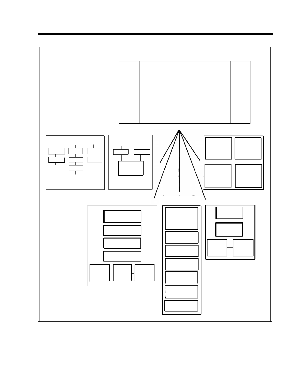
stations and modem pooling. Refer to Figure 1-1 for an
example of MERLIN II system configuration.
1-2 System Overview
Page 6
MERLIN II System control unit
Modern pool types
Digital Digital Digital
port port port
MTDM
Modern Modern
2500 Port
MTDM
BTMI
Analog
port
MTDM
Modern
Central
office
line
Analog voice and data
Voice Terminal
Voice Terminal
Voice Terminal
General
Purpose
Adapter
Power
supply
Local host access
Digital Digital
port port
MPDM MPDM
Host
Computer
Display
Console
34-Button
22-Button
10-Button
Modem
Processor
module
Terminal
or PC
Analog
station
module
Accessories/auxlliary
equipment
Telephone
and Modem
Interface 2
Music
Coupler
Single/Multizone
Paging
Alerter
Accessories
MERLIN II
Attendant
Basic
telephone
module
Basic
Tie
line
module
Digital voice and data
PT510D
Digital
Voice/Data
7406D
Digital
Voice
Basic voice and data
Modem
Digital
station
module
7406D/with
display
Digital Voice
7406D/with
Data Stand
Digital
Voice/Data
2500 Type
telephone
500 Type
telephone
Terminal
or PC
FIGURE 1-1 MERLIN II system configuration.
Answering
machine
Printer
System Overview 1-3
Page 7

SYSTEM CONFIGURATION
The size, type, and features of a MERLIN II system are
determined using system planning forms.
System Size
A MERLIN II system can be as small as four outside lines
and eight analog voice terminals, or as large as 56 outside
72
lines and
stations. A MERLIN II system with as many
as eight lines and 20 stations is considered a small system
for administration purposes.
Basic and expanded system capabilities are determined by
these system hardware maximum limitations:
●
Thirty-six analog stations with the Simultaneous Voice
and Data feature
●
Sixty-four digital stations with the Simultaneous Voice
and Data feature
● Eleven line pools
●
Seventy-one off-premises devices or Basic Telephone
and Modem Interfaces
System Type
A system can be configured for pooled, square, or behindswitch operation. The MERLIN II system default
configuration is pooled with button access.
●
In a square system, each outside line has a dedicated
position on a voice terminal. This arrangement is also
known as a key system. In a standard square
configuration, outside lines appear on the same buttons
on each voice terminal. In a customized square
system, different groups of outside lines are assigned
to the same buttons on selected groups of voice
terminals.
1-4 System Overview
Page 8

●
In a pooled system, outside lines can be grouped into
line pools (groups of interchangeable lines). To get an
outside line in a pooled system, the user must dial an
access number or use a dedicated pool button on the
voice terminal. Access to outside line pools can also
be had through Automatic Route Selection (ARS).
●
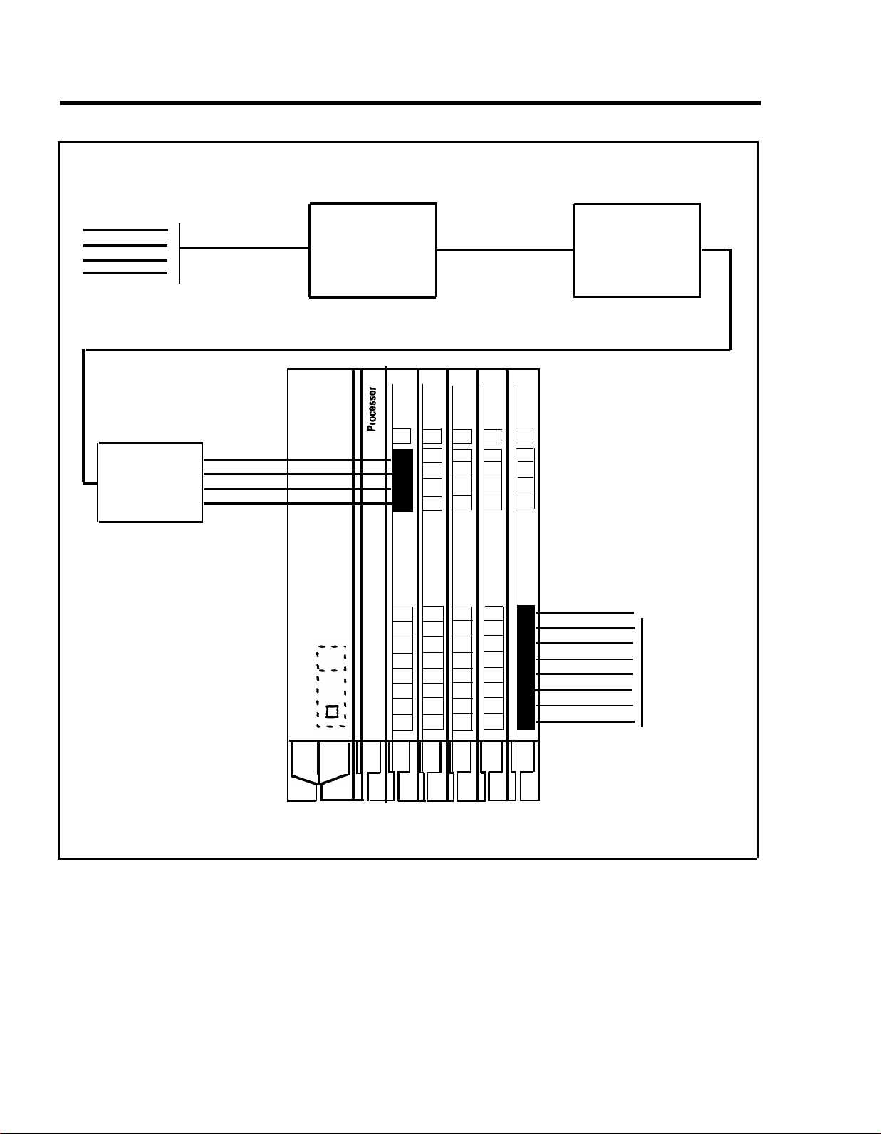
In a behind-switch system, the MERLIN II system
operates behind a larger system such as a System 25,
75, or 85 PBX. In this configuration, most features of
both systems are available to the MERLIN II system
user. Refer to Figure 1-2 for an example of a MERLIN
II system operating behind a digital PBX.
System Overview 1-5
Page 9
Central
office
lines
\
25 Pair cable
/
Network
interface
66 Type
hardware
DIW cable
DIW cable
Digital PBX
(System 25,
System 75,
or System 85)
Jack Field
for outside
lines
Z122C Box
with
Z61OA
Adapters
D2R
cords
Power
Supply
408 408 408 408 408
PFT
04
03
02
01
08
07
06
05
04
03
02
01
PFT
08
07
06
05
16
15
14
13
12
11
10
09
PFT
12
11
10
09
24
23
22
21
20
19
18
17
PFT
16
15
14
13
32
31
30
29
28
27
26
25
PFT
20
18
17
40
19
39
38
37
36
35
34
33
D8W
cords
\
To voice
terminals
and
adjunct
equipment
/
MERLIN II System
contol unit
FIGURE 1-2 A MERLIN II system behind-switch operation.
1-6 System Overview
Page 10

SYSTEM FEATURES
Table 1-1 lists the features that are available for
MERLIN II System Feature Modules 1 and 2, and
Release 3.
NOTE:
The features in Table 1-1 are described fully in
MERLIN II Communications System System
the
Manual.
The following paragraphs describe feature that are either
new in Release 3 or have been significantly modified for
Release 3.
●
Disallowed List.
Using a Disallowed List, you can
create up to eight lists of numbers, area codes, or
exchanges that selected users will not be permitted to
dial. Each list can have up to 10 numbers. The
administrator may assign one or more of these lists to
any station in the system. If a station is assigned so a
disallowed list any attempt to dial a number contained
in the list wiIl be denied.
●
Extended Station Status.
Extended Station Status (ES
Status) indicates the operating status of other stations
to the administrator. When ES Status is administered
for Hotel/Motel mode, the attendant can put voice
terminals into different categories to indicate whether
the room is occupied. With Release 3, if the voice
terminal is off-hook, the attendant can’t change its
status. This ES Status Inhibit feature helps prevent
hotel guests from making calls from their room after
they have checked out.
NOTE:
The alternative to Hotel/Motel mode is Call
Management System (CMS) mode. CMS is
the automatic call distributor (ACD) for the
MERLIN II system, and is available only with
Feature Module 1 or 2,
not
Release 3. The
CMS component of the MERLIN II system
answers calls and connects them to available
agents. CMS is not a system feature and
requires a separate software package.
System Overview 1-7
Page 11

●
MERLIN II Attendant. The MERLIN II Attendant
automatically answers and routes incoming calls. The
feature is available only when the optional MERLIN II
Attendant accessory is installed. Also, to gain access
to this feature, you
must
use the517C13 Basic
Telephone (012) Module.
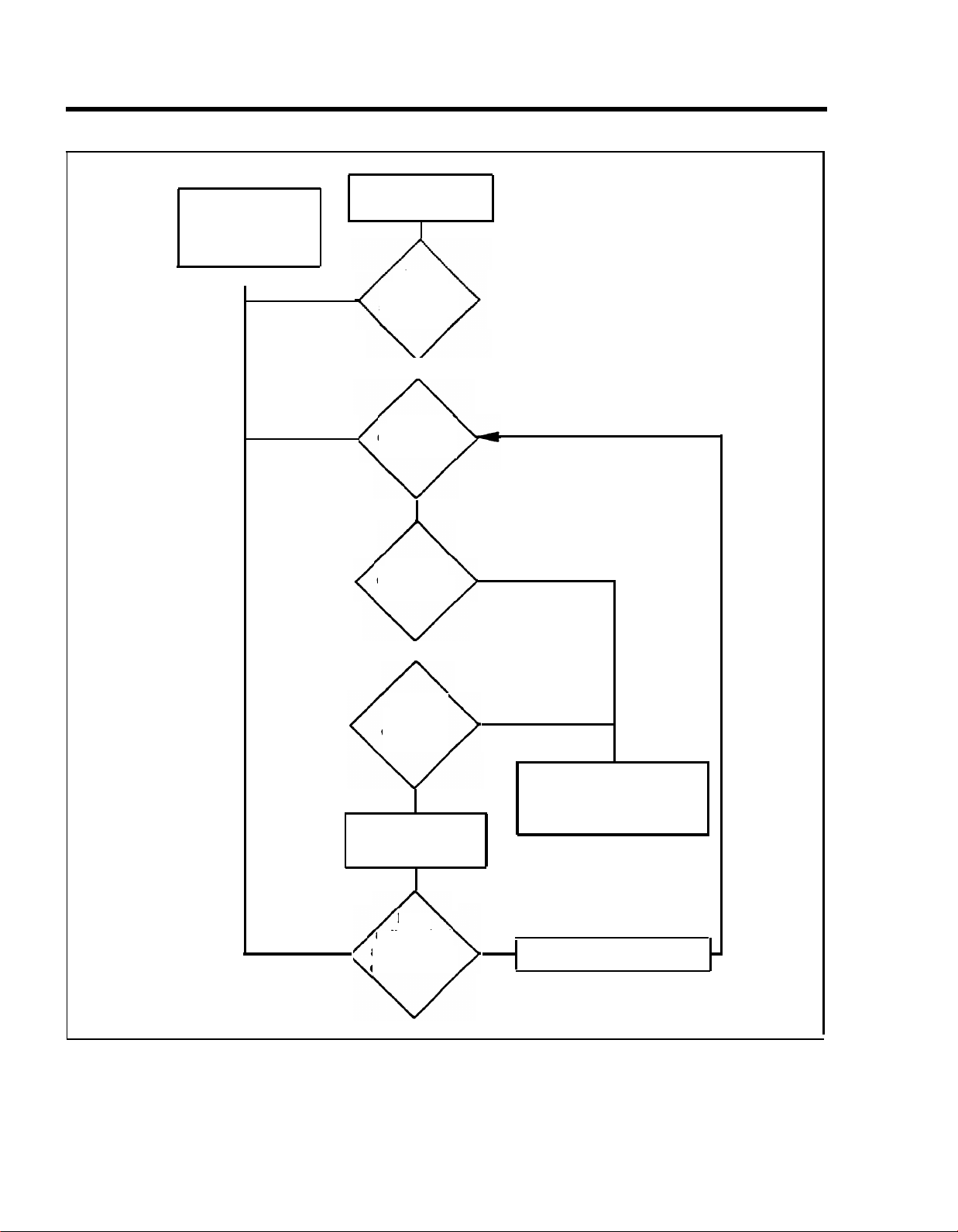
The MERLIN II Attendant performs two major
functions (Figure 1-3):
Immediate call handling, in which all incoming
>
calls are received and routed by the MERLIN II
Attendant. Multiple MERLIN II Attendants can
be used to handle call groups.
Backup call handling, in which incoming calls are
>
directed to the MERLIN II Attendant if the
receptionist (Station 10) does not answer within a
predetermined number of rings.
Each of these functions includes night service call
handling in which the MERLIN II Attendant maybe
used for call coverage only after normal business
hours.
●
On-Line Module Swap.
The On-Line Module Swap
feature allows you to replace a module in the control
unit without powering the system down. The
replacement module must be the same as the one
removed (i.e., a 408 module must be replaced with a
408 module). To use this feature, it is necessary to
follow the exact procedures described in “On-Module Swap,w on page 4-7.
●
Page All.
This feature allows you to page all
telephones in the system at once over voice terminal
speakers.
1-8 System Overview
Page 12

●
Posted Message.
The Posted Message feature
provides a method of sending one of 20 user-defined
messages to another terminal. Each message can be up
to 16 characters long and will appear on the caller’s
display.
●
System Speed Dial.
System Speed Dial allows the
caller to store frequently used numbers as three-digit
codes. For Release 3, the feature has been enhanced to
accommodate 130 speed dial numbers.
●
Tie Lines.
The MERLIN II system interfaces to a tie
line with E&M signaling through a Tie Line Module.
This feature permits the interconnection of a MERLIN
II system to another MERLIN II system or to other
switches such as a System 25,75, or 85 PBX. (See
“E&M Signaling” on page 1-45 for a description of
E&M signaling.)
System Overview 1-9
Page 13
Call transferred to
receptionist;
MERLIN II Attendant
disconnects
▲
No
MERLIN II Attendant
answers call.
Caller
enters route
or extension
number.
No
Route
or extension
valid?
Yes
Route
or extension
answers?
No
Second
route or
extension
answers?
No
MERLIN II Attendant
plays Transfer Fail
announcement.
Yes
Yes
call transferred; connection
announcement played;
MERLIN II Attendant
disconnects.
Does
No
caller select
another route
or extension?
Yes
FIGURE 1-3 MERLIN II Attendant operation.
1-10 System Overview
Repeat process
Page 14

TABLE 1-1 MERLIN II System Features
Feature
Account Code Entry
Allowed List
Attendant (Automatic) [MERLIN II Attendant]
Attendant Barge-in
Attendant Position Setting
Auto Answer All
Auto Answer-Intercom
Auto Intercom
Automatic Line Selection (ALS)
Automatic Route Selection (ARS)
FM1 FM2
1
x
x
x
x
x
x
x
x
x
x
x
x x
x x
x x
Release 3
x
x
x
2
x
x
x
x
x
x
x
Basic Telephones
x x
Behind-Switch Operation
3
Bridging on Shared Lines
Call Coverage
1 The feature name is "Account Number Entry- for Feautre Module 1.
2 The feature name is ‘Executive Barge-In
3 The feature name is “Bridging” for Feature Module 1 and Feature Module 2
-
for Release 3 and can be used from any voice terminal.
x
x
x
x
3
x
x
x
x
x
System Overview 1-11
Page 15
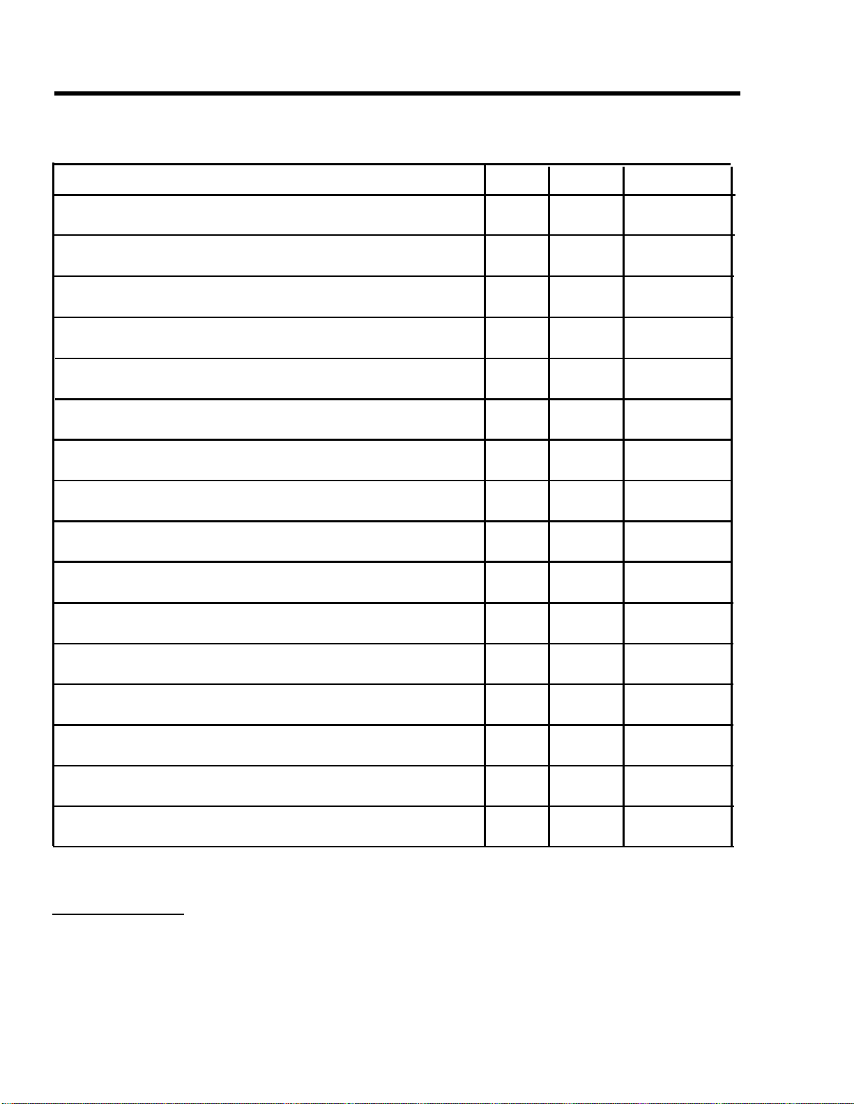
TABLE 1-1 MERLIN
II
System Features (continued)
Feature
Call Forwarding and Follow Me
Call Park
Call Pickup
Call Pickup Groups
Call Report (SMDR)
Call Restriction
Camp On
Centralized Programming
Conference
Coverage Inhibit
FM1
FM2
Release 3
x x
x x x
4
x
4
x
x
x
x
x
x x
x x
x
x
x
x x
x x
x
4
x
x
x
x
Dialing Timeout Internal for Rotary Lines
Direct Inward System Access (DISA)
x
x
x
Disallowed List
Display
Do Not Disturb
Drop
4 This feature in Feature Module 2 and Release 3 is the same as "Line Pickup” in Feature Module 1.
x
x x
x x
x
x
x
x
x
x
x
1-12 System Overview
Page 16
TABLE 1-1 MERLIN II System Features (continued)
Feature
Executive Barge-In
Extended Station Status (ES Status)
Flexible Numbering
Follow Me
Forced Account Code Entry (FACE)
Group Call Distribution (GCD)
Group Listening
Group Page
Hold
Hold Disconnect Interval
FM1
x
x
x
x
x
FM2 Release 3
5
x
x
x
x
x x
x
x
x
x x
6
x
x
x
7
x x
x
x
x
x
Intercom
Intercom Dial Tone
Labels for Lines and Stations
Last Number Redial
5 For Feature Module 2, the feature name is “Attendant Barge-In” and it operates only from an attendant
station.
6 For Release 3, the feature name is “Call Forwarding and Follow Me”
7 The information for this feature is found in Section 2, "System Components," of the System Manual for
Release 3.
8 For Feature Module 2, the feature name is "labels for Stations” and it is limited to stations only.
x x
x x
x
x x
8
x
x
x
System Overview 1-13
Page 17
TABLE 1-1 MERLIN II System Features (continued)
Feature
Leave Word Calling
Line Assignments in Behind-Switch Systems
Line Assignments in Pooled Systems
Line Assignments in Square Systems
Line Pickup
Line Representation Setting
Line Request
Loudspeaker Page
Manual Signaling
Menu Driven Administration
FM1
x
FM2 Release 3
x
x
9
x
10
x
11
x
x
x
x
x
x x
12
x
x x
x
x
x x x
x
x
x
x
12
x
13
x
Message
Monitor-on-Hold
9 The feature name is "Line Pools" for Feature Module 1.
10 The feature name is "Square Line Configuration" for Feature Module 1.
11 This feature is called "Call Pickup" for Feature Module 2 and Release 3.
12 The feature name is “System Type” for Feature Module 2 and Release 3.
13 This is not technically a feature of MERLIN II System with Release 3, since menu-driven is the only
administration method for that release. See “Overview” in Section 3, "Reference," of the Release 3 System
Manual for information on menu-driven administration.
14 The information for this feature is found in Section 2, "System Components," of the System Manual for
Release 3.
x x x
x
x
14
x
1-14 System Overview
Page 18

TABLE 1-1 MERLIN II System Features (continued)
Feature
Music-on-Hold
Night Service
Notify
On-Hook Dialing
On-Line Module Swap
One-Touch Hold with Call Announcement
Outside Auto Dial
Page All
PBX, Centrex, or Custom Calling Features
Personal Speed Dial
FM1
FM2 Release 3
x x
x
x
x
x
x
x
x x x
x
x
x x
x
x
x
x
x
15
x
x
x
x
x
Personalized Ringing
Posted Message
Privacy
Reed
Recall Timer Interval
Reminder Service
15 The information for this feature is found in Section 2, "System Components," of the System Manual for
Release 3.
x
x
x x x
x
x
x
x
x
x
x
x
x
x
System Overview 1-15
Page 19

TABLE 1-1 MERLIN II System Features (continued)
Feature
Ringing/Idle Line Preference
Ringing-on-Transfer
Ringing Options
Saved Number Redial
Send Message
Simultaneous Voice and Data Calls
Special Characters in Programmed Dialing Sequences
Stopwatch
System Renumbering
System Size
FM1
16
x
x
x x
x
x
x
x
x
x
17
x
FM2
Release 3
x x
x
x
x x
x x
x
x
x
x
x
x
x
x
x
x
x
System Speed Dial
System Type
Test
16 The feature name is “Ringing Line Preference” for Feature Module 1.
17 The feature name is “System Size Setting- for Feature Module 1.
18 This feature name is "Line Represention Setting" for Feature Module 1.
19 The information for this feature is found in Section 2, "System Components," of the System Manual for
Release 3.
x
18
x
x
x
x
x
x
x
19
x
1-16 System Overview
Page 20
TABLE 1-1 MERLIN II System Features (continued)
Feature
Tie Lines
Tones
Touch-Tone Enable
Touch-Tone or Rotary Signaling
Transfer
Transfer Return Interval
Type of Telephone
Voice Announcement Enable/Disable
Voice Announcement to Busy Telephone
FM1
x
x
21
x
x
x
22
x
x
23
x
FM2
x
x
x
x
x
22
x
x
23
x
Release 3
x
20
x
x
x
x
x
x
x
x
20 The information for this feature is found in Section 2, “System Components,” of the System Manual for
Release 3.
21 The feature name is "Touch-Tone or Rotary Setting" for
22 The feature name is "Voice Terminal Type Setting" for Feature Module 1, and "Voice Terminal Type" for
Feature Module 2.
23 The feature name is "Voice Announcement to Busy Voice Terminal" for feature Module 1 and Feature
Module 2.
Feature
Module 1.
System Overview 1-17
Page 21

System Hardware
MERLIN II SYSTEM
COMPONENTS
CONTROL UNIT COMPONENTS
The MERLIN II system includes the following hardware:
●
Control unit
Voice terminals
●
> Analog
> Digital
●
Basic Touch-Tone
●
Digital data equipment
●
Modems
●
System accessories/auxiliary devices
The assembly of modules containing a power source, a
processor, and jack connections for outside lines, tie lines,
MERLIN II system telephones, and other devices mounted
on a carrier is called the control unit (Figure 1-4). The
individual components are as follows:
●
Basic carrier.
The basic carrier is the main housing
for the control unit. Every MERLIN II system must
have at least one basic carrier, which houses the Power
Supply Module, Processor Module, and up to five line
and/or station modules.
● Expansion carrier. The expansion carrier provides
slots for an additional Power Supply Module and six
line and/or station modules. The expansion carrier
does not require a Processor Module.
1-18 System Hardware
Page 22
Basic carrier
FIGURE 1-4 Control unit components.
●
Power Supply Module. The Power Supply Module
receives an input of 117 VAC and supplies the system
with the following dc voltages: +5, -5, and -48 VDC.
The Power Supply Module can support up to 45 unit
loads per carrier. (A unit load is a measure of power
used to determine the electrical load of the MERLIN II
system.) if the system’s power requirements exceed 45
unit loads, an Auxiliary Power Unit must be used. This
device supplies an additional 20 unit loads to the
system. For more information on unit loads and the
Auxiliary Power Unit refer to “Determining Unit Load
Requirements” on page 2-57.
If the system uses Basic Telephone (012) Modules, a
Frequency (Ring) Generator must be installed in the
Power Supply Module.
Expansion
carrier
System Hardware 1-19
Page 23
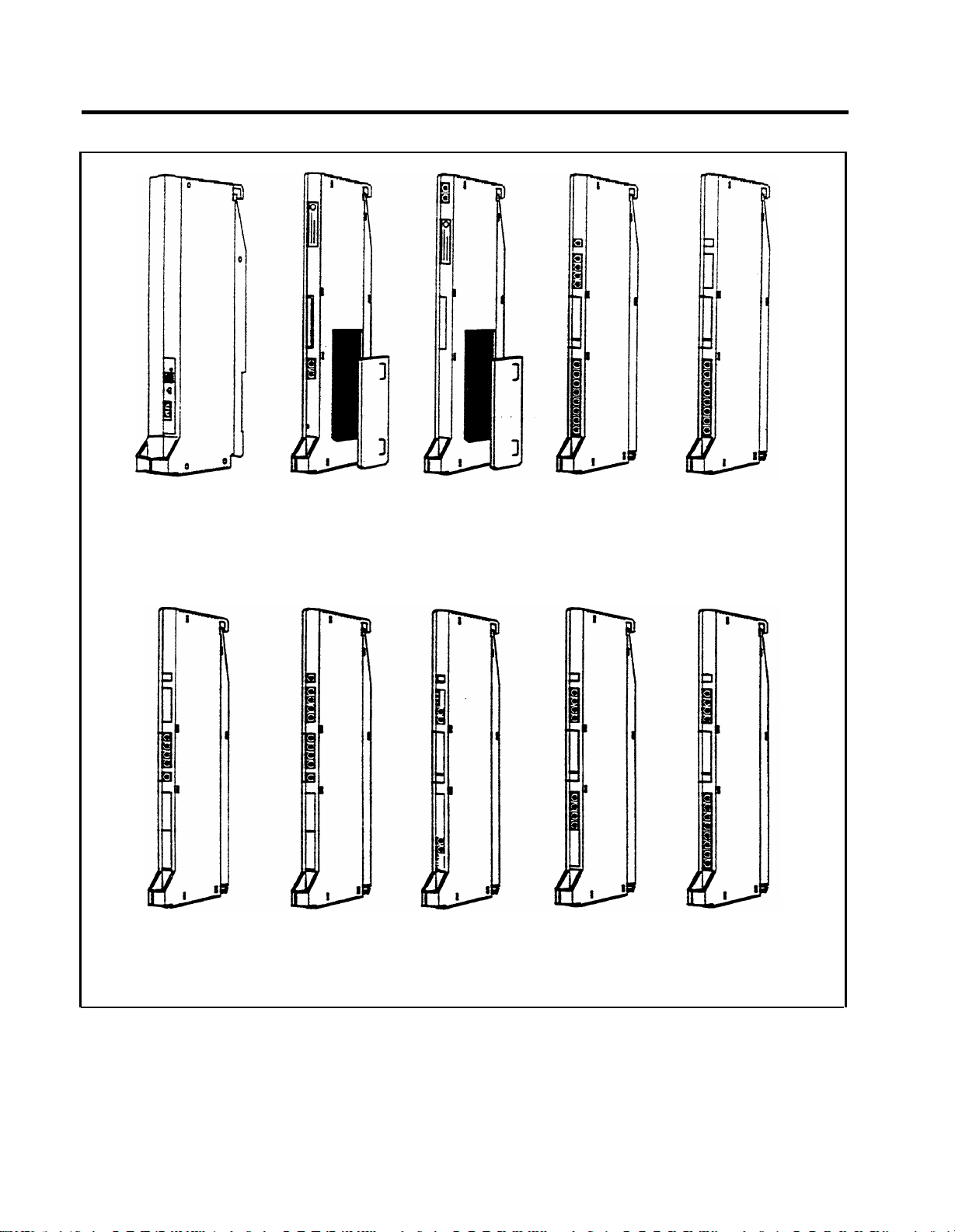
Power supply
module
Processor
module (R3)
(with feature
module)
Processor
module
(FM1 and 2)
(with feature
module)
Line/station
module
(408)
Station
module
(000)
Line module
with DTMF
(400)
Line
module
(800)
Tie line
module
(400EM)
FIGURE 1-4 Control unit components (continued).
1-20 System Hardware
Digital
station-module
(008D)
Basic
telephone
module
(012)
Page 24

●
Processor Module.
The Processor Module contains
the circuitry that controls the system’s programs and
features. It houses the Feature Module. Release 3 of
the MERLIN II System must use Processor Module
517B7 with Feature Module 517F6.
● Feature Module. The Feature Module contains the
Read Only Memory (ROM) and Random Access
Memory (RAM) for the system features. It is housed
inside the Processor Module. The MERLIN II Release
3 Feature Module(517F6) must be used only with the
517B7 Processor Module.
● Line and station modules. Line and station modules
provide jacks for the system’s tie lines, outside lines,
and stations. Line and station modules can occupy
slots 1 through 5 in the basic carrier and slots 6
through 11 in the expansion carrier. There is no
required slot assignment for line and/or station
modules except that the module in slot 1 of the basic
carrier must be a 408 or 008 module. Either of these
modules provides the user with an analog station port
(port 01) to administer the system.
> Analog line and station modules:
—
4-Line/8-Analog (408) Module.
module is required for a MERLIN II system
minimum configuration. It has four jacks for
outside lines and eight jacks for analog
stations. The 408 module has a Power Failure
Telephone (PFT) jack for connecting a Basic
Touch-Tone or rotary telephone for backup
during power outages. The system
automatically switches service to this jack in
the event of a power failure.
Simultaneous voice and data is available but
requires you to connect both an odd and even
numbered jack to the same voice terminal.
The 408
System Hardware 1-21
Page 25

– 8-Analog (008) Module. The 008 module has
jacks for eight analog stations. It has no jacks
for outside lines. Simultaneous voice and data
is available but requires you to connect both
an odd and even numbered jack to the same
voice terminal.
– 4-Line (400) with DTMF Module. The 400
module has jacks for four outside lines and one
PFT jack. The board has four Touch-Tone
receivers.
– 8-Line (800) Module. The 800 module has
jacks for eight outside lines and two PFT
jacks.
>
E&M Tie Line (400 EM) Module. A tie line is a
transmission facility dedicated to interconnect two
private switching systems. The MERLIN II system
Tie Line Module may be connected to another
system locally or many miles away. Tie lines are
provided by the telephone company.
>
Digital (008D) ModuIe. The 8-station digital
module interfaces digital voice and data equipment
to the system. Simultaneous Voice and Data is
available on every port.
>
Basic Telephone (012) Module. The Basic
Telephone Module permits Touch-Tone or rotary
telephones to be used with the MERLIN II system.
This module provides 12 station jacks and supplies
the tip/ring interface and Touch-Tone circuitry
needed for basic telephones. This module requires
the installation of the Frequency Generator in the
Power Supply Module.
The 517CI 3 Basic Telephone Module must be
installed in order to use the MERLIN II Attendant.
1-22 System Hardware
Page 26

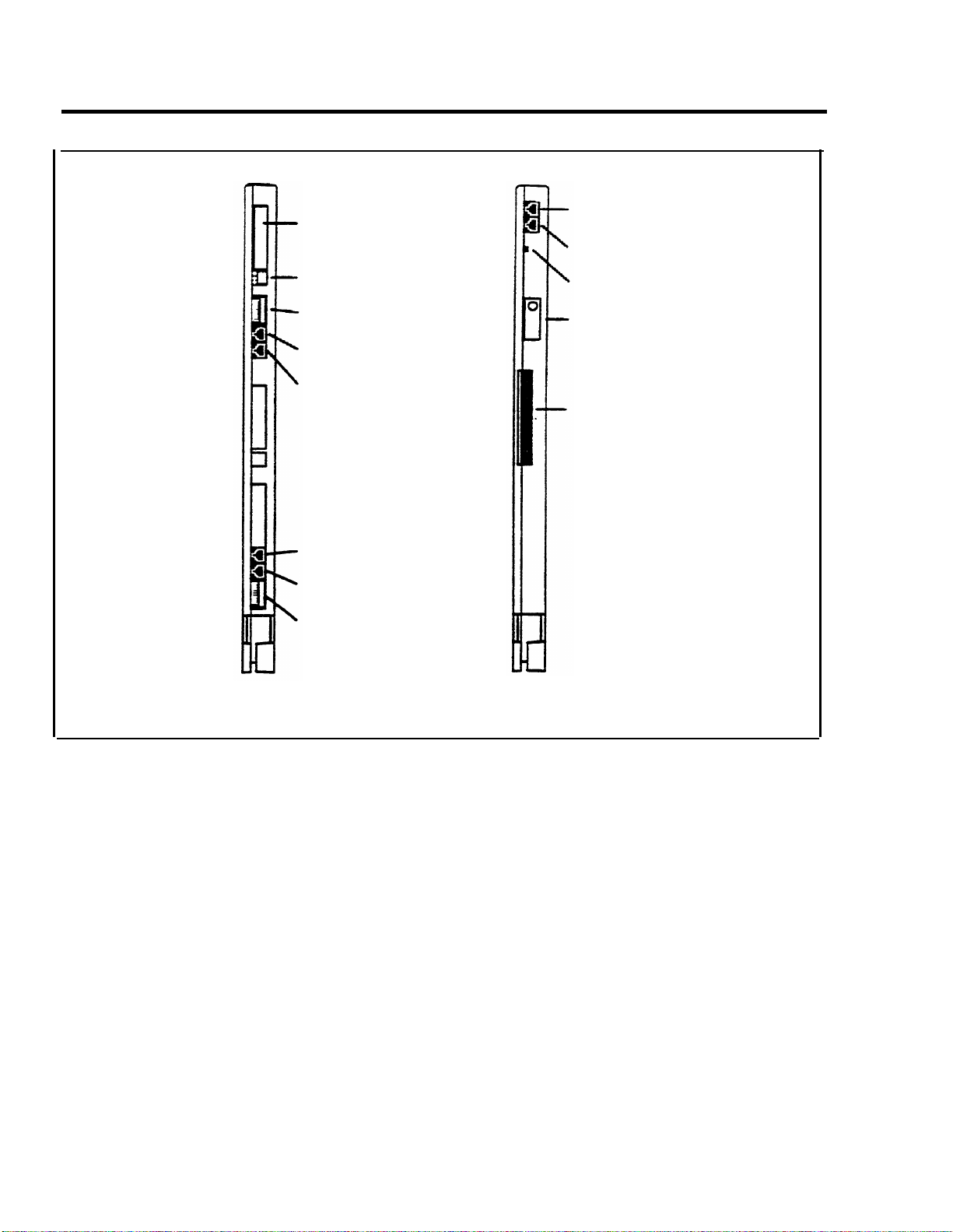
Label
Power indicator
Auxiliary power
input jack
On/Off switch
Power
connector
Ground lug
Power supply module
FIGURE 1-5 Module controls and indicators.
MODULE CONTROLS AND INDICATORS
The from panel controls, indicators, and special
connectors (excluding line and station jacks) on control
unit modules are described below. Refer to Figure 1-5 to
locate these items.
Diagnostic
96-pin connector
SMDR port
Application port
Warning light
Pr
ocessor module (517B7)
for Release 3
Power Supply Module.
The controls and indicators for
this module are the following:
●
Power indicator. Its light goes on when power is
supplied to the module.
●
Auxiliary power input jack This jack provides the
interface for the Auxiliary Power Unit.
System Hardware 1-23
Page 27
Label
SMDR port
Application port
Status indicators (LEDs)
DIP switch (S2)
Port 4
Port 3
Port 2
Port 1
DIP switch (S1)
Tie line module (517A14)
Warning iight
label
Diagnostic
96-pin connector
Processor module (517A7)
for Feature Moduies 1 and 2
FIGURE 1-5 Module controls and indicators (continued).
●
On/off switch. This switch applies or removes power
to the earner.
●
Power connector. This is a male connector for the ac
power cord.
●
Ground lug. This connects the control unit chassis to
an approved ground for the building.
1-24 System Hardware
Page 28

Processor Module.
This module has the following port
and light:
● SMDR port. This port is an interface to Station
Message Detail Recording (SMDR) for call reports on
call activity or a printout of system administration.
●
Warning light. When this red light is lit it indicates
that there is a problem with either the Feature Module,
line or station module, or the Processor Module.
Tie Line Module. The controls and indicators for this
module are the following:
●
Status indicators (LEDs). The three status indicators
show the condition of the Tie Line Module.
Green = test condition
Amber = busy
Red = standby mode
●
Dual In-Line Package (DIP) switch (S2). This switch
controls the signaling format for tie line ports 3 and 4.
VOICE TERMINALS
●
DIP switch (S1). This switch controls the signaling
format for tie line ports 1 and 2.
●
Ports 4 through 1. These ports are jacks for tie lines.
Voice terminals are the user’s link to the MERLIN II
system. They are designed to allow easy access to system
features, and have various buttons and indicators to
facilitate operation The buttons on a voice terminal can
function as line buttons or feature buttons. There are fixed
feature buttons for the transfer, hold, recall, conference
and drop features.
Each analog voice terminal has a Test/Program (T/P)
switch that allows testing, programming, and normal
operation. Digital voice terminals are programmed using
a dial code. Other controls on a voice terminal include a
message button, speaker volume control, speaker ON/OFF
button, and red and green lights to indicate status of lines
and features.
System Hardware 1-25
Page 29

Voice terminals work like special input/output (I/O)
devices. The control unit performs all the decision making
for the system while voice terminals act as the system’s
sensors. Voice terminals inform the control unit of button
depressions and feature status. They also inform the user
of specific conditions by flashing lights or generating
tones.
Voice terminals are connected to the control unit by a
4-pair wire. Each pair has a specific function:
●
Voice 1 pair. The control unit uses this pair of wires
for the primary audio path to and from the voice
terminal. The control unit selects this pair to complete
the path for outgoing, incoming, and intercom calls.
●
Control pair. The control unit receives information
on voice terminal status and user input on this pair of
wires. It also uses this path to send ringing and lighting
instructions to the voice terminal.
●
Power pair. This pair provides power to the voice
terminal.
●
Voice 2 pair. The control unit uses this pair of wires
for the secondary audio path to and from the voice
terminals. This pair is used with the analog voice
terminal to provide the Voice Announcement to Busy
Voice Terminal and the Simultaneous Voice and Data
features.
Voice terminals used with the MERLIN II system are
listed here. Refer to Figure 1-6 for examples of analog
voice terminals, including the MERLIN II Display
Console. Figure 1-7 shows digital voice terminals.
1-26 System Hardware
Page 30

● Analog voice terminals
>
7102A
>
5-Button
>
10-Button
>
10-Button HFAI
10-Button with Built-In Speakerphone (BIS-10)
>
BIS-22
.>
BIS-22 with Display
>
>
34-Button
>
34-Button Deluxe
>
34-Button (SP-34)
>
34-Button (SP-34D)
>
BIS-34
>
BIS-34 with Display
>
Display Console (used to administer a system with
Release 3)
NOTE:
The new 7102A single-line voice terminal
(not illustrated) has been certified for the
MERLIN II system. It is the same as a basic
telephone and must be connected to a 012
module.
●
Digital voice terminals
> 7406D
> 7406D with Display
> 7406D with Data Stand
> 7406D with Display and Data Stand
System Hardware 1-27
Page 31

10-Button
10-Button
HFAI
BIS-10
BIS-22D
with display
BIS-34
34-button
BIS-34D
with display
Display console
FIGURE 1-6 A selection of analog voice terminals.
1-28 System Hardware
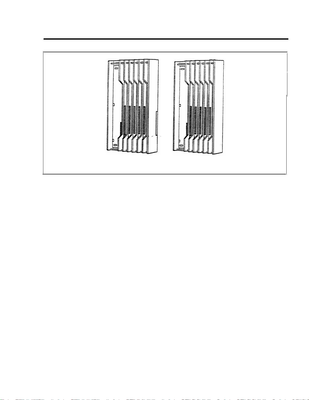
Page 32

7406D with
Data Stand
FIGURE 1-7 A selection of digital voice terminals.
7406D with
display and
Data Stand
BASIC OPERATION OF VOICE TERMINALS
Voice terminals perform a variety of functions. With a
voice terminal, a user can make and receive intercom and
outside calls, page someone, and, with the proper voice
terminal (the attendant console), administer the MERLIN
II system. Buttons on voice terminals maybe
programmed for different functions. The following
paragraph describe the basic operations of voice
terminals.
●
Administration. Two voice terminals, the Display
Console and the BIS-34D, can be used to administer
systems with Feature Module 1 and Feature Module 2.
The Display Console, however, is the only voice
terminal that can administer new MERLIN II Release
3 features. The voice terminal used for administration
must be connected to station jack 01 on the control
unit. During administration, the voice terminal
Test/Program switch must be set to “Program”. This
switch is set to the center position during normal
operation
System Hardware 1-29
Page 33

●
Dialing out or in.
When a voice terminal goes offhook, it signals the control unit to make a connection
through a network switch to an available or requested
outside line. When the path is established, the voice
terminal receives a dial tone. The control unit will
select a path in its multiplexing scheme to make the
connection. A call coming into the will
activate the ring indicator in the control unit and
generate control signals to alert the voice terminal.
●
Intercom call.
Intercom calls can be made from one
voice terminal to-any other voice terminal connected to
the control unit. Dialing the intercom number of
another voice terminal will cause the control unit to
establish a voice path between both voice terminals.
●
Loudspeaker paging.
The system interfaces with
auxiliary equipment such as a power amplifier and
loudspeaker for single or multiple zone external
paging.
●
Programming.
In programming mode, instructions
keyed into a voice terminal are stored in the control
unit’s memory; the voice terminal itself has no
memory. When a particular feature is requested by a
voice terminal, the control unit examines its memory to
determine the features for that station.
For an analog voice terminal, you enter and exit
programming mode by using the T/P switch. For a
digital voice terminal, which doesn’t have a T/P
switch, you must use a dial code to enter and exit
programming mode. For a basic voice terminal, the
administrator must program any feature changes.
●
Telephone paging.
The MERLIN II system allows
paging over voice terminal speakers. The Group Page
feature allows paging to a maximum of 10 voice
terminals. The Page All feature allows paging to all
voice terminals in the system.
1-30 System Hardware
Page 34

SYSTEM ACCESSORIES
Figure 1-8 shows several of the MERLIN II system
accessories described here.
●
Alerter Accessories.
Devices such as a horn, bell,
strobe, or chime can be connected to a Supplemental
Alert Adapter so that people working in noisy or
remote areas of a building can be alerted to incoming
calls.
●
Attendant Intercom Selector.
Can be attached to a
34-Button Deluxe voice terminal when a MERLIN
system has more than eight lines or more than 20 voice
terminals. A system attendant can use the selector’s 30
buttons to access up to 120 Auto Intercom numbers.
The light beside each button indicates whether a voice
terminal or basic telephone is busy and whether a
voice terminal’s message light is on.
●
Auxiliary
Power Unit. This unit must be added to the
control unit if the total number of voice terminals and
voice terminal accessories (including Hands-Free
Units and Headset Adapters) is greater than the control
unit’s power capacity. The control unit supports up to
45 unit loads, and each Auxiliary Power Unit adds 20
unit loads to the system.
●
Basic Telephone and
Modem Interface.
The BTMI
connects telephones and data communications devices
such as autodialers, answering machines, cordless
telephones, facsimile machines, and modems to the
MERLIN II system. A timer may be connected to a
BTMI for automatic answering based on time of day.
The BTMI is no longer available, having been
replaced by the BTMI-2. The BTMI supports more
features than the BTMI-2, however, including the
Conference and Drop features, and line selection. For
customers who already have the BTMI, it can be used
with MERLIN II systems with Feature Module 1,
Feature Module 2, and Release 3.
System Hardware 1-31
Page 35

Basic Telephone and Modem
interface 2 (BTMI-2)
Off-Premises Telephone
Interface (OPTI)
General Purpose
Adapter (GPA)
In-Range Out- of-
Building Protectors (IROB)
Hands-Free Unit (HFU)
Headset with Headset Adapter
Indoor
bell
Extra alert
strobe
Alerter accessories
FIGURE 1-8 A selection of MERLIN II system accessories.
Indoor
horn
Indoor/outdoor
alerter
1-32 System Hardware
Page 36

● Basic Telephone and Modem Interface 2 (BTMI-2).
The BTMI-2 is a replacement for the BTMI. It
connects telephones and data communications devices
such as autodialers, answering machines, cordless
telephones, facsimile machines, and modems to the
MERLIN II system. A timer may be connected to a
BTMI-2 for automatic answering based on time of day.
Unlike the BTMI, the BTMI-2 does not support
Conference, Drop, or line selection features. It can be
used with MERLIN II systems with Feature Module 1,
Feature Module 2, and Release 3.
●
Basic Telephones.
Basic Touch-Tone telephones,
connected to the MERLIN system with the OffPremises Telephone Interface (OPTI) and to outside
telephone lines, provide service to people at a remote
location. On-premises Basic Touch-Tone telephones
can be connected to the system with a Basic Telephone
and Modem Interface 2 or a Basic Telephone Module.
●
Frequency Generator.
If your basic carrier or
expansion carrier has a Basic Telephone (012)
Module, you must connect a Frequency Generator to
the Power Supply Module, located in the first slot of
each carrier containing Basic Telephone Modules.
The Frequency Generator converts 117-volt, 60-Hz
input power to 105-vol~ 30-Hz ringing voltage for
basic telephones connected to the Basic Telephone
Module.
●
General Purpose Adapter
(GPA). Permits
connection of accessories such a modem with PCs or
data terminals, cordless telephones, and autodialers to
a MERLIN II system voice terminal. To use this
accessory, you must program Auto Answer AU. The
GPA is for use with all analog voice terminals except
5-button and 10-button HFAI.
System Hardware 1-33
Page 37

●
Hands-Free Unit (HFU).
Provides the voice terminal
user with full speakerphone capability. This includes
hands-free telephone conversation, on-hook dialing,
monitor-on-hold, and teleconferencing at a short
distance from the voice terminal. To use this
UtO
accessory, you must program A
Answer- Intercom.
The HFU is for use with all analog voice terminals
except 5-button and 10-button HFAI. An HFU used
with a 7406D voice terminal requires a local power
unit.
●
Headset-and-Headset- Adapter.
Enables a user
to
answer and listen to calls without lifting the handset.
The headset and headset adapter is for use with all
analog voice terminals except 5-button and 10-button
HFAI.
●
In-Range, Out-of-Building (IROB) Analog Voice
Terminal Protectors.
A voice terminal can be placed
in another location outside of the main building but
within 1000 feet of the MERLIN H system control
unit. IROB protectors protect the control unit and
voice terminal from exposure to lightning, contact with
power lines, and power currents induced by nearby
power lines.
1-34 System Hardware
●
Loudspeaker Paging System.
An optional
loudspeaker paging system allows people with
MERLIN II system voice terminals to page co-workers
and/or make announcements through loudspeakers.
●
Music Coupler.
A music coupler connects a music
source (such as a cassette player) to the MERLIN II
system. It also provides a secondary bridged
connection to provide Music-on-Hold. In addition, it
allows the music source to be connected to a
loudspeaker paging system to provide background
music at the same time.
Page 38

●
Off-Premises Range Extender (OPRE).
The OPRE
will be available in place of the Off-Premises
Telephone Interface (OPTI) for users of Feature
Module 1, Feature Module 2, and Release 3. The
OPRE will allow users to connect off-premises
Touch-Tone Basic telephones to the MERLIN II
system.
NOTE:
As of this printing the Off-Premises Range
Extender is not available. Installation
information will be supplied in a CIB with the
product.
●
Off-Premises Telephone Interface (OPTI).
Connects off-premises Touch-Tone Basic telephones
to the MERLIN II system. Allows you to use an offpremises telephone to access many of the features of
the on-premises communication system. The OPTI is
used with MERLIN II Feature Module 1. It can also
be used with Feature Module 2 and Release 3, but only
for two-digit intercom numbers.
●
Power Failure Telephone.
A power failure telephone
allows calls to be made and received in case of a
power failure. A Basic Touch-Tone or rotary
telephone, when connected to a Power Failure
Telephone jack on a module in the control unit, bridges
onto the lowest line number in the block of jacks that it
serves on the module when a power outage occurs.
●
Supplemental Alert Adapter.
Allows Extra Alert
Devices, such as a horn, bell, strobe, or chime, to be
connected to an analog voice terminal jack so that
people working in noisy or remote areas of a building
can be alerted to incoming calls.
System Hardware 1-35
Page 39

Theory of Operation
SYSTEM
ARCHITECTURE
The MERLIN II system architecture provides a digital
network that supports voice and data communications.
The modular nature of the system makes the base
configuration efficient and easy to expand. The control
unit contains the memory for the system’s features,
Input/Output (I/O) functions, and interface requirements.
The various modules are electrically connected to a
backplane assembly that provides common circuitry for
the I/O bus, Time Division Multiplex (TDM) bus, and
power distribution. Refer to Figure 1-9 for a fictional
block diagram of MERLIN II system architecture. System
architecture is made up of the following items: a
Processor Module interconnected to intelligent port
modules by an I/O bus; a communications network made
up of a TDM bus connected to the DigitaI Switch Element
(DSE) of each module; and a Power Supply Module.
1-36 Theory of Operation
Page 40

FIGURE 1-9 System architecture.
Theory of Operation 1-37
Page 41

●
Power Supply Module.
The Power Supply Module
converts 117 VAC line voltage to the following
outputs: +5 VDC, -5 VDC, and -48 VDC (tip/ring).
●
Processor Module.
The central processor complex
consists of a main board and the Feature Module. The
main board contains the 68000 microprocessor, RAM,
a real-time clock, interrupt circuitry, and port interface
to the modules through the I/O bus.
Communication between the Processor Module and
the port processors on the various modules occurs over
a parallel address/data bus. This structure allows
memory-mapped I/O with up to 1 megabyte per second
bandwidth.
●
Input/Output Bus.
Included in the I/O bus are a 16bit address bus and an 8-bit data bus. The address bus
selects the module that receives instructions from the
68000 microprocessor. The microprocessor provides
instructions to the port processors and Digital Switch
Elements (DSEs) through the 8-bit data bus.
●
Time Division Multiplex Bus.
The Time Division
Multiplex bus (TDM) is a major part of the control
unit. It connects the DSEs to allow voice and data to
flow in and out of the MERLIN II system. The TDM
bus is parallel, 8 bits wide, and runs at 2.048 MHz.
Each TDM cycle has 256 time slots for voice, data,
tones, and clocks.
Voice signals on the TDM bus are encoded in “Mu-
Law 255” Pulse Code Modulation (PCM) format for
domestic use and “A-Law 100” for international
applications. See “Analog to Digital Signal
Processing” on page 1-40. Data signals are processed
according to Digital Communications Protocol (DCP).
●
408 or 008 Module.
A 408 Loop Start Line/ATL
Station Module or 008 module is required in slot 1 of
the basic carrier of the control unit. Note, however,
that the 008 module does not provide any outside lines
1-38 Theory of Operation
Page 42

If you use a 008 module in this slot, you must provide
for outside lines using another module.
The 408 module has a port processor to handle real-
time intensive tasks such as ATL line protocol and
central office rotary outpulsing. The port processor
receives instructions from the main processor over the
I/O bus. The instructions are stored in the dual port
RAM. Buffer circuitry interfaces the I/O bus to the
port processor.
The 408 module converts analog signals to digitaI for
switching. Analog signals come into the 408 module
through the outside lines and are converted to digital
levels by coder-decodes (codecs). Voice and data
signals going to the station jacks are converted to
analog signals by codecs. Interface circuitry couples
the analog output to the station jack. The DSE
interfaces voice and data with the TDM bus. The main
processor (through the 1/0 bus) directs the DSE to
place or remove samples from the TDM bus in specific
time slots.
●
008D Module.
The 008D Digital Module provides a
digital interface to the system for PCs and other data
devices. This module does not require codecs because
no analog to digital conversion is required. Data flow
through the module is controlled by the port processor,
which receives its instructions from the I/O bus. Dual
Line Interface (DLI) circuitry assures proper clocking
and synchronization during all transfer cycles.
●
012 Module.
The 012 Module interfaces basic
telephones to the MERLIN II system. It provides the
-48 VDC tip/ring voltage and monitors the circuit for
tip/ring conditions. The 012 module converts analog
signals into digital levels for interface to the TDM bus
and provides -24 VDC for the Ring relay. When a
basic telephone goes off-hook and dials a number, ring
control circuitry closes the ring voltage relay. At this
point, ring control circuitry outputs signals to the port
Theory of Operation 1-39
Page 43

processor. The port processor directs Touch-Tone
circuitry to output tones. The tones are placed on the
TDM bus by the DSE through buffer circuitry. After a
tip condition occurs at the remote end, a conversation
may occur.
ANALOG TO DIGITAL
SIGNAL
PROCESSING
Analog to Digital
Signal Conversion
The MERLIN II system receives analog signals from the
central office lines and analog modules. In order to be
switched, the analog signals must be converted to digital
signals. Digital transmissions have several advantages
over analog transmissions. They produce superior bit
error rates and have lower noise/signal degradation,
simpler circuitry in some cases, and greater flexibility.
They also have various performance advantages, such as
speed and a nonblocking architecture.
If an analog signal is sampled in increments equivalent to
twice the frequency of that signal, then the sample can
faithfully reproduce the signal at a digital level.
The first step in analog to digital conversion is to sample
the pulse amplitude of the analog signal. Then the sample
is converted into a series of amplitude steps. This
technique is referred to as Pulse Amplitude Modulation
(PAM). Analog to digital converters (codecs) are an
integral part of voice and data systems. Codecs use a
variety of encoding techniques. The MERLIN II system
uses Pulse Code Modulation (PCM).
1-40 Theory of Operation
The process of converting an analog signal to a digital
level increases the capacity and efficiency of data
transmissions. However, a digitized analog signal retains
some of the problems of older transmission systems, such
as having to be amplified.
Page 44

PCM uses PAM as its starting point but goes further.
PCM digitizes the information and sends the 8-bit code via
PAM. PCM digitizes the PAM information by comparing
each PAM sample to a point on a chart. Each point has a
distinct 8-digit binary code. Therefore, it is the binary
code, not the amplitude pulse, that is transmitted in PCM.
Quantizing
Commanding
The process of converting PAM samples into discrete
PCM values is known as “quantizing”. In the case of voice
grade signals eight bits are commonly used to encode one
PAM sample. Quantizing with eight bits allows 256
unique values to represent the analog signal being
sampled. With adequate sampling of an analog voice
signal, the digital product can be toll quality.
The quantizing process creates errors due in part to the
“rounding off” of PAM samples into discrete PCM values.
This distortion can be minimized by increasing the number
of bits used to sample the analog signal or to increase the
sampling rate.
Distortion also occurs in the quantizing process because
equal consideration is given to all amplitude levels. Linear
quantizing divides the amplitude range into equal
segments which results in unnecessary quality at levels
where voice signals are unlikely to occur. Commanding
eliminates this distortion by using a nonlinear scale which
has smaller divisions and more accuracy in areas of the
scale where voice signals are most likely to occur.
Commanding is, in effect, a compression/expansion of the
quantizing scale. This nonlinear scale is more accurate in
areas where signal amplitudes occur most (thereby
reducing quantizing distortion). The scale is less accurate
in areas where signal amplitudes occur least (resulting in
more quantizing distortion).
Theory of Operation 1-41
Page 45

Mu-Law 255
Mu-Law 255 is a commanding scheme which uses a
compression ratio that is compatible with modern channel
bank equipment. The scale is divided into 16 intervals,
with each interval having 16 levels. Therefore, it has 256
discrete values. Mu-Law 255 has a negative and positive
zero; therefore, it really has 255 discrete values. This
commanding scheme is used in the United States and
Japan.
A-Law 100
DIGITAL SWITCHING
The commanding scheme used in Europe is A-Law. It
follows the same basic theory as Mu-Law 255 except that
its scale is different. The scale tends to be more linear than
Mu-Law 255. Because the intends tend to be equal, ALaw 100 does not concentrate its accuracy in areas of the
scale where voice signals occur the most.
The Time Division Multiplex (TDM) bus allows many
users to communicate over a common electrical
connection. The TDM bus is physically distributed across
the backplane of the control unit and connects all
line/station modules. It is 8 bits wide and has a frequency
of 2.048 MHz. The frame repetition rate is 8 KHz
providing a 64 Kbps channel on each of the 256 time slots.
The TDM bus has specific time slots for various functions.
During a conversation between station A and station B, a
time slot is reserved for station A to transmit on and
another for station B to receive on. Because the TDM bus
cycles 8 thousand times per second, the conversation is
continuous. The TDM bus carries tones and control
signals to stations. Unlike other bus configurations, the
stations on the TDM bus receive all transmissions. If a
station is not assigned to any of the time slots, the TDM
bus will ignore the data. Refer to Figure 1-10 for an
example of the TDM bus.
1-42 Theory of Operation
The Digital Switch Element (DSE) functions as a digital
switch for voice and data. It also performs the operations
for commanding schemes such as A-Law and Mu-Law.
Page 46

Each module has a DSE to interface codecs or digital
transceivers to the TDM bus. The actual digital switching
occurs when the DSE is programmed by the system I/O
bus to place (transmit) data or retrieve (receive) data on
the TDM bus in specific time slots. This process also
involves time slot interchanging so that an available slot in
the TDM cycle can be filled with a talk (transmit) or listen
(receive) slot. The DSE provides dynamic conferencing
ability by allowing up to 16 time slots to be conference
together and sent out to a single port (station).
DSE
0 1 2 3
Time slots
for control
signals.
408 Module
CODEC
D/A
converter
A/D
converter
…
i
n
t
e
Analog
r
voice
f
a
terminal
c
e
TDM Bus
256 Time slots in one TDM cycle
60 61 62 63
Time slots
for tones.
…
FIGURE 1-10 Time division multiplexing.
DSE
150 … 160
Analog station
talks on time
slot 150 and
listens on time
slot 160. The
conversation
is continuous.
008D Module
…
200 … 220 … 225
Interface
circuity
Time
Digital station
sends data on
time slot 200
and receives
data on time
slot 220.
Theory of Operation 1-43
Page 47

SYSTEM CAPACITY
The MERLIN II system hardware limits the system
capacity for the items found in Table 1-2.
TABLE 1-2 MERLIN II System Capacity
Item
Module slots
Board signatures
Time slots
-
Simultaneous duplex connections
Tones
Capacity
17
16
256
108
40
Table 1-3 lists items that the system architecture either
allows or requires.
TABLE 1-3 Port Requirements for Features and System
Accessories
Feature
Port Requirements
1-44 Theory of Operation
Music-on-Hold interface
1 CO line (administered)
External paging interface
Analog Simultaneous Voice/Data
Analog Voice Announcement
to Busy Voice Terminal
Digital Simultaneous Voice/Data
Extra alert devices (with SAA)
1 ATL station port
1 CO line (administered)
2 ATL station ports
2 ATL station ports
1 DCP station port
Page 48

E&M SIGNALING
Most signaling systems, other than loop signaling, are
separate from the trunk equipment. They are normally
located between the trunk equipment and the line facility.
E&M signaling systems derive their name from the
historical designations of the signaling leads on
schematics covering these systems. By convention, the
"E" stands for ear and the "M" stands for mouth (rEceive
and transMit). The E&M lead signaling interface consists
of two leads between the switching equipment (central
office) and the signaling equipment (PBX). The “M lead
carries signals from the switching equipment to the
signaling equipment. The “E” lead carries return signals
from the signaling equipment to the switching equipment.
The E&M interface is designated as TL31M, and the 50-
pin connector is designated as RJ2GX. At the RJ2GX
interface, the PBX is the switching equipment side, and
the network side (toward the central office) is the
signaling equipment side. An example of E&M signaling
is shown in Figure 1-11.
Theory of Operation 1-45
Page 49

MERLIN II
System
T
R
T1
R1
M
E
RJ2GX
Central
office
Central
office
RJ2GX
T1
R1
T
R
E
M
Dimension
PBX
SITE #l
Off-hook
Dial tone
Site #1 dials
number for
site #2
On-hook
M lead
E lead
E lead
M lead
FIGURE 1-11 E&M signaling.
M lead of site #1 connected to
E lead of site #2
M lead of site #2 connected to
E lead of site #1
Conversation
Disconnect
Disconnect
SITE #2
E lead
Ring
Off-hook
M lead
On-hook
M lead
E lead
E&M Tie Line
Parameters
1-46 Theory of Operation
The MERLIN II system 400EM Tie Line Module has four
line ports. Each must be administered individually. All tie
line options are software administered except for the
signaling format parameters (signaling mode and signaling
type). These are selected by DIP switches on the Tie Line
Module. The following is an explanation of tie line
options. For more information, see “Administering Tie
Lines” on page 3-50 in Section 3, “Administration”.
Page 50

Direction
A tie line may be administered in one of the
three following ways:
●
Two-way (default): Calls may be made in either
direction.
●
Outgoing only: Calls may be made but not received.
●
Incoming only: Calls may be received but not made.
Type
●
There are four types of tie line options.
Wink start (default): The originating end of the tie line
transmits an off-hook signal and waits for the remote
end to send a signal indicating that it is ready (a wink).
This is also
●
Automatic start: Incoming calls are routed directly
know as
a dial repeating tie line.
to
an attendant station without a start signal. This is also
known as an automatic ringdown tie line.
●
Immediate start: No start dial signal is necessary.
Dialing may begin immediately following seizure of a
line. This is also known as a dial repeating tie line.
●
Delay dial start: The originating end of the tie line
transmits an off-hook signal and waits for the remote
end to send a delay dial signal (an off- hook signal
followed by an on-hook signal). This is also known
as
a dial repeating tie line.
Signaling Mode
Signaling mode designates the
electrical interface used.
●
E&M mode: The signaling leads are isolated from the
transmission leads. The E&M mode can be either
protected or unprotected.
WARNING:
The protected mode must be used
whenever the E&M leads extend out-of-building
and are not connected to the network interface.
Theory of Operation 1-47
Page 51

●
Unprotected mode: Must be used for the E&M
Type 1 Standard interface in order to meet voltage
drop criteria for the interface. This mode is used
when there is a network interface.
●
Protected mode: Resistance is added in tie M lead
to provide additional protection from foreign
voltages and transients. This mode is used on local
tie lines, such as between systems in different
buildings.
●
Simplex mode: The signaling leads are superimposed
onto the analog transmission leads to provide a twopair interface. Resistance is included in the signaling
leads for protection from foreign voltages and
transients. This mode is used primarily with E&M
Type 5 signaling on local tie lines.
Signaling Type
Signaling type designates the logical
signaling used. There are the following three options:
●
Type 1 Standard (default): The M leads are used for
signaling from PBX to line. Off-hook is -48 VDC and
on-hook is local ground. Signaling in the other
direction uses local ground for off-hook and open for
on-hook.
●
Type 1 Compatible: This interface is back-to-back
compatible with Type 1 Standard. It allows direct
connection between systems where no intermediate
signaling equipment is used.
●
Type 5: A symmetrical 2-wire arrangement that signals
in both directions by means of open for on-hook and
ground for off-hook. The primary application of Type5 interface is local tie lincs.
1-48 Theory of Operation
Page 52

Dialing Mode
This option sets the dialing mode for the
tie line.
●
Touch-Tone
●
Rotary (default)
Dial Tone
This option determines whether the dial tone
originates from the remote or local end of the tie line, or
both (you receive a second dial tone).
●
Remote (default)
●
Local
Answer Supervision Time
This option sets a time limit
in milliseconds (ms) for the remote station to signal the
calling station.
●
20 to 4800 ms (increments of 20 ms)
●
300 ms (default)
Tie Line Disconnect Time
This option sets a time limit
for the release of the E or M lead.
●
140 to 2400 ms (increments of 10 ms)
●
300 ms (default)
Your choice of signaling format (signaling mode and type)
depends on the particular application. Using Table 1-4
“Tie Line Preferred Signaling Formats,” you can
determine tie line compatibility between the MERLIN II
System and other systems.
Theory of Operation 1-49
Page 53

TABLE 1-4 Tie Line Preferred Signaling Formats
Installation Situation
From
MERLIN II System
To
MERLIN II
Location
Same Site
MERLIN II System
Signaling
Mode and
Type
Simplex
Preferred Signaling Format
Protected
or
Unprotected
N/A
Signaling
Mode and
Type Unprotected
Simplex N/A
System or Inter- Type 5 Type 5
building
System 25
Same Site
System 75 or Inter-
Simplex N/A Simplex
Type 5 Type 5
building
System 85
Same Site
or Inter-
Simplex N/A
Type 5
Simplex
Type 5
building
Far End
Protected
or
N/A
N/A
Dimension
Same Site
PBX
Dimension InterPBX
Other
building
Same Site
E&M
Type 1
Compatible
E&M
Type 1
Compatible
E&M
Type 1
Compatible
Unprotected E&M Unprotected
Type 1
Standard
Protected
E&M Protected
Type 1
standard
Unprotected
E&M
Unprotected
Type 1
Standard
1-50 Theory of Operation
Page 54

TABLE 1-4 Tie Line Preferred Signaling Formats (continued)
Insulation Situation
Preferred Signaling Format
From
MERLIN II System MERLIN II System
Signaling Protected Signaling
Mode and or
To
Location
Other Inter- E&M
Type Unprotected Type Unprotected
Protected
building Type 1
Compatible
Network
interface
…
E&M
Type 1
Unprotected Either
Standard
Far End
Protected
Mode and
E&M
or
Requires a
Type 1 protection
Standard
unit
Either
Theory of Operation 1-51
Page 55

System Connectivity
This section describes typical hardware configurations for
a MERLIN II system with accessories and auxiliary
equipment Connectivity diagrams with descriptions are
provided for the following:
●
Simultaneous voice and data (analog station) using the
analog station module (408) to gain access to a remote
host computer.
●
Simultaneous voice and data (digital station) and local
host computer access using the digital station module
(008D).
●
Modem pool using the digital station module (008D)
and the basic telephone module (012).
●
Modem pool using the digital station module (008D)
SIMULTANEOUS VOICE AND DATA
and the analog station module (408).
●
Modem pool on dedocated outside lines for data-
●
Background music provided for callers through
Music-on-Hold.
●
External loudspeaker paging.
Simultaneous voice and data at an analog station allows
the user to connect to the system an analog voice terminal
and a data terminal or PC with data rates set by the
modem. This feature requires both an odd and even jack
to be connected to the voice terminal. Refer to the
connectivity diagram in Figure 1-12.
Simultaneous voice and data at a digital station allows the
user to have a digital voice terminal and a data terminal or
PC with data rates up to 19,200 bps between digital
1-52 System Connectivity
endpoints. Note that between the Modular Trunk Data
Module (MTDM) and the modem there can be a maximum
of 17 feet. Refer to the connectivity diagram, especially
Note 2, in Figure 1-13.
Page 56

Remote
host
computer
Modem
Central
Office
Bridging
adapter
BR 241-B1
Even Station Odd
■ ■ ■
D8W
cord
Analog
voice
terminal
■ Line
Power
Supply
408 408 408 408 408
PFT
PFT
PFT
PFT
PFT
04
03
02
01
08
07
06
05
04
03
02
01
08
07
06
05
16
15
14
13
12
11
10
09
12
11
10
09
24
23
22
21
20
19
18
17
16
15
14
13
32
31
30
29
28
27
26
25
20
19
18
17
40
37
36
35
34
33
39
38
cord
See Notes 1
and 2
D8W
cord
D8AC
D4BU
Other
■
cord
■
VT
General
Purpose
Adapter
Tel Equip
■
cord
■
Line
Modem
2212C
Terminal
■
RS-232-C
(M25B)
MERLIN II System
Control unit
Notes:
1. Bridging adapter connects adjacent odd/even jacks (23, 24) to analog voice terminal.
This type of connection is required for features such as Voice Announcement to
Busy Telephone or Simultaneous Voice and Data.
2. Total distance between the control unit and the voice terminal cannot be more than
1000 feet without local power.
Data
terminal
or PC
FIGURE 1-12 Simultaneous voice and data (analog station).
System Connectivity 1-53
Page 57

LOCAL HOST COMPUTER ACCESS
Local host computer access allows shared use of the host
computer through Modular Processor Data Modules
(MPDMs). The MPDMs may have different data rates or
the same rate, each set to a data rate of 19,200 bps or less.
Refer to the connectivity diagram in Figure 1-13.
MODEM POOLS
Connected to Basic
Telephone Jack
Connected to Analog
Station Jacks
Modem pools are groups of modems and associated
equipment used to convert digital data signals to analog
data signals or vice versa. Putting modems in pools makes
to
it easier for users
share a limited number of modems.
Each modem pool is used exclusively for either incoming
or outgoing calls.
The modem pool members use available basic telephone
jacks to send data between digital endpoints and remote
to
computers over MERLIN II system lines. Refer
in
connectivity diagram
Figure 1-14.
the
The modern pool members use available analog station
jacks to send data between digital endpoints and remote
computers over MERLIN II system lines. Refer to the
connectivity diagram in Figure 1-15.
Connected to
Dedicated Outside
Lines
1-54 System Connectivity
The modem pool members use dedicated outside lines to
send data betwecn digital endpoints and remote
computers. This type of modem pool would likely be used
if thcrc were many data calls to remote computers in order
II
to save the MERLIN
system lines for voice use. Refer
to the connectivity diagram in Figure 1-16.
Page 58

Power
Supply
408 408 408 408 008D
PFT
04
03
02
01
08
07
06
05
04
03
02
01
MERLIN II System
control unit
PFT
08
07
06
05
16
15
14
13
12
11
10
09
PFT
12
11
10
09
24
23
22
21
20
19
18
17
PFT
16
15
14
13
32
31
30
29
28
27
26
25
D8W
cord
20
19
18
17
36
35
34
33
D8W
cord
PT 510D
Digital
voice
and data
See Note 2
MPDM
DCP
■
jack interface
MPDM
DCP
■
jack
MPDM
DCP
■
jack
MPDM
DCP
■
Jack
See Note 1
D8W
cord
PT 510D
Digital
voice
and data
DCE
DCE
interface
DCE
interface
DCE
interface
■
See Note 3
RS 232-C
(M25B)
■
■
■
D8W
cord
400B2 Adapter
D8W
cord
7406D with
Data Stand
See
Note 4
Data terminal
RS-232-C
or PC
■
■
■
computer
■
(M25B)
Local
host
D6AP
cord
KS-22911L1
Power supply
Notes:
1. The cable distance between the control unit and a MPDM, PT 510D, or 7406D
with data stand cannot be more than 1000 feet.
2. Some host computers act as DCE devices in which case the MPDMs will need to
be replaced with MTDMs or special wiring. If an MTDM can be used, the switch
settings are the same as an MPDM, but you don't need to set auto answer.
3. The cable distance between the MPDM or MTDM and the local host computer cannot
be more than 17 feet.
4. The cable distance between the 7406D and the data terminal cannot be more than
50 feet.
FIGURE 1-13 Simultaneous voice and data (digital station) and local host computer
access.
System Connectivity 1-55
Page 59

Power
Supply
408 408 408 012 008D
PFT
PFT
PFT
36
35
34
33
16
15
14
13
04
03
02
01
08
07
06
05
12
11
10
09
D8W cord
1000' max.
Modem
pool
-------------------------------
08
07
06
05
04
03
02
01
16
15
14
13
12
11
10
09
24
23
22
21
20
19
18
17
32
31
30
29
28
27
26
25
MTDM
40
39
38
37
2212C
Modem
-------------------------------
D4BU cord
1000' max.
MTDM
RS-232-C
(M25B) 17 max.
2212C
Modem
MERLIN II System
control unit
FIGURE 1-14 Connectivity of a modem pool using a basic telephone module.
1-56 System Connectivity
Page 60

Power
Supply
408 408 408 408 008D
PFT
08
07
06
05
16
15
14
13
12
11
10
09
PFT
12
11
10
09
24
23
22
21
20
19
18
17
PFT
04
03
02
01
08
07
06
05
04
03
02
01
MERLIN II System
control unit
PFT
16
15
14
13
32
31
30
29
28
27
26
25
20
19
18
17
36
35
34
33
D8W cord
----------------------------
Telephone
and Modem
Interface 2
Modem pool
MTDM
2212C
Modem
Basic
MTDM
RS-232-C (M25B)
17' max.
2212C
Modem
D4BU cord
Basic
Telephone
and Modem
Interface 2
-----------------------------
D8W cord
1000’ max.
FIGURE 1-15 Connectivity of a modern pool using an analog station module.
System Connectivity 1-57
Page 61

Power
Supply
408 408 408 408 008D
PFT
PFT
08
07
06
05
PFT
12
11
10
09
16
15
14
13
20
19
18
17
PFT
04
03
02
01
RS-232-C (M25B)
17’ max.
/
/
2212C
Modem
2212C
Modem
Central Office
08
07
06
05
04
03
02
01
16
15
14
13
12
11
10
09
24
23
22
21
20
19
18
17
32
31
30
29
28
27
26
25
36
35
34
33
D8W cord
1000' max.
--------------------------
MTDM
MTDM
----------------------
Modem pool
MERLIN II System
control unit
FIGURE 1-16 Connectivity of a modern pool on dedicated outside lines.
GENERAL REQUIREMENTS FOR MODEMS
Modems are an essential part of MERLIN II system
features involving local and remote computer access. Any
modem other than the 2212C used with system hardware
should meet the following requirements to ensure proper
operation under all conditions. Modem requirements
differ according to applications. When planning the
system, remember the various modem configurations such
as a single modem for analog voice/data or modem pools.
The planning information recorded on the individual
Station Configuration forms should reflect the exact
modem arrangement for each station.
D4BU to
line jack
1-58 System Connectivity
Page 62

The following paragraphs describe the basic requirements
for any modem, and specific requirements when used in
outgoing and incoming modem pools.
Basic Requirements
for Modems
NOTE:
Modems
can meet these requirements through
fixed features or through hardware and software
options that can be set. An option setting may
make a modem appropriate for one pool in the
MERLIN II system but not another.
The basic-requirements for modems are the following:
Full-duplex operation, for switched networks
●
A single speed between 300 bps and 19,200 bps
●
●
Serial transmission of characters in a binary
asynchronous format
●
EIA RS-232-C interface
Peak signal level compatible with the MERLIN II
system
Modular jack connection for telephone network
●
Requirements for
Outgoing Modem
Pools
●
Loss of earner disconnect so that the modem goes onhook and turns received line signal detector, EIA lead
RLS (carrier on) off
Disconnect if EIA lead DTR (data terminal ready) goes
●
off
●
Passing of break character and long space signal
Saving of options during power outage
●
In addition to meeting the basic requirements, a modem
used for outgoing calls must have the following
characteristics:
System Connectivity 1-59
Page 63

●
Touch-Tone dialer that can pause and dial characters 0
through 9, #, and *
●
Detection of dial tone
●
Ability
to take terminal dialing instructions
(compatible parity and character length with the
MTDM)
●
EIA (RS 232-C) lead DSR and RLS on before a call is
placed (follows DTR)
Requirements for
Incoming Modem
Pools
MUSIC-ON-HOLD
EXTERNAL LOUDSPEAKER PAGING
In addition to meeting the basic requirements, a modem
used for incoming calls must have the following
characteristics:
●
Auto-answer feature
●
Compatible parity and character length with MTDM
Music-on-Hold provides background music for callers
who have been placed on hold. It requires the use of a
music coupler. You must reserve a line jack for a music
source such as a radio, tape player, or stereo system. To
make it easier to add outside lines in the future, use the
last line jack(s) on the rightmost line module for the
Music-on-Hold connection. Refer to the connectivity
diagram in Figure 1-17.
Refer to the connectivity diagram in Figure 1-18. External
loudspeaker paging allows you to connect a single or
multizone paging system through a line jack on the
MERLIN II system. Background music can also be
provided by connecting a music coupler and a music
source.
1-60 System Connectivity
Page 64

Speaker
8-Ohm wire
J5
Power
Supply
408 408 408 408 408
PFT
04
03
02
01
08
07
06
05
04
03
02
01
PFT
08
07
06
05
16
15
14
13
12
11
10
09
PFT
12
11
10
09
24
23
22
21
20
19
18
17
PFT
16
15
14
13
32
31
30
29
28
27
26
25
PFT
20
19
18
17
40
39
38
37
36
35
34
33
(Paging)
(Music)
D4BU cords
4BU cord
103A
connecting
block
12345678
103A
connecting
block
12345678
(Page input)
J1
Page Pac 20
Powermate
Music In
13
14
15
4PT
5PR
Loop
start
trunk
adapter
29R
30T
PBX
26
J2
27
MERLIN II System
control unit
AC line cord
Auxiliary
■
output
■
Music Out
Music
coupler
Background music
117 VAC
●
■
source
Standard
patch cord
Standard phonograph patch cord
FIGURE1-17 Connectivity of single-zone paging with Music-on-Hold.
124v
source
GND
Power
supply
Music
System Connectivity 1-6
Page 65

Power
Supply
408 408 408 408 408
D4BU
cord
●
Page
input
J1
P1
Page
input
Music in
Switch
CK LS
DL GS
Page Pac 20
Powermate
Common control
unit
PFT
PFT
PFT
08
04
03
02
01
08
07
06
05
04
03
02
01
07
06
05
16
15
14
13
12
11
10
09
12
11
10
09
24
23
22
21
20
19
18
17
MERLIN II System
control unit
PFT
16
15
14
13
32
31
30
29
28
27
26
25
PFT
20
19
18
17
40
39
38
37
36
35
34
33
Page
port
Music
port
D4BU
cord
D4BU
cord
ooooooooo
Speaker
Speaker
Speaker
BKGND
●
Music
coupler
Music out
Music in
Standard
phonograph
patch cords
Music
source
FIGURE 1-18 Connectivity of multizone paging with background music and
Music-on-Hold.
1-62 System Connectivity
Page 66

Section 2: installation
Preinstallation Requirements
Reviewing the Planning Forms
Environmental Requirements
Spare and Location Requirements
Power Requirements and Secifications
Grounding Requirements
Wire Length Limitations
Wall Attachment Requirements
System Grounding Requirements
System Ground Connection
AC Outlet Tests
CO Line Protector
Surge Protectors
IROB Protectors
Static Discharg
Radio-Frequency Interference
e Problems
2-1
2-1
2-1
2-2
2-2
2-3
2-3
2-4
2-5
2-5
2-7
2-8
2-8
2-9
2-9
2-9
Wiring the System
Typical MERLIN II System Wiring
Module Jacks
Outside Line Wiring
Preparing the Network Interface
Testing the Outside Lines
Connecting Outside Lines to the Control Unit
Tie Line Module Wiring
Voice Terminal Wiring
Connecting Voice Terminal Wiring to the Control Unit
Wiring a Voice Terminal for Two Voice-Pairs
Standard 4-Pair Wiring
2-12
2-30
2-12
2-14
2-17
2-17
2-19
2-19
2-21
2-23
2-23
2-27
Page 67

Jack Field Wiring
Constructing a Jack Field for Voice Terminal Wiring
Connecting Voice TerminaI Wiring to a Jack Field
2-33
2-35
2-37
Extending the Network Interface to a Jack Fieid
for Outside Lines
2-41
Wiring Reference Tables
Installing the Control Unit
Control Unit Components
Mounting the Basic Carrier
Mounting the Expansion Carrier
Determining Unit Load Requirements
De
termining Module Slot Assignments
Module Installation
Installing a Module
Removing a Module
Insralling the Power Supply Module
Installing the Auxiliary Power Unit
Installing the Feature Module on the Processor Module
Installing Line and Station Modules
Connecting a Printer to the ControI Unit
Connecting the Control Unit to an AC Outlet
Power to the System
2-45
2-50
2-50
2-52
2-56
2-57
2-61
2-62
2-63
2-64
2-66
2-72
2-73
2-79
2-81
2-90
2-90
Connecting the Voice Terminals
Assembling the Voice Terminals
Connecting Voice Terminals to the System
Testing the Voice Terminals
Labeling Each Voice Terminal
Connecting the Power Failure Telephone
Testing the PFT Jacks
2-92
2-93
2-95
2-95
2-96
2-97
2-99
Page 68

Testing the System
2-100
Testing the Voice Terminal Jacks for a Dial Tone
Testing Intercom Calls
Testing Outside Lines
Testing Tie Lines
Completing the Installation
Attaching the Control Unit Covers
Modifying the System
Adding an Outside Line
Adding a Voice Terminal
Moving a Voice Terminal
Adding Accessories
General Accessories
Power Accessories
2-100
2-101
2-103
2-104
2-106
2-106
2-112
2-112
2-113
2-115
2-117
2-117
2-122
Upgrading an Existing System
Site Preparation
Get a Printout of the Existing System
Upgrade Instructions FMl or FM2 to R3
Upgrade Instructions FMl to FM2
2-131
2-131
2-132
2-133
2-136
Page 69

Preinstallation Requirements
REVIEWING THE PLANNING FORMS
Review the completed system planning forms, which
should be on site, before starting installation. The forms
for Release 3 are titled:
●
Form la, System Form—Incoming Lines
●
Form 1b, System Form—Tie Lines
●
Form 1c, System Form—Module Identification
Diagram
●
Form 1d, System Form—Station Planning
●
Form 1e, System Form—Requirements and Options
The forms for Feature Modules 1 and 2 are titled:
●
Master Planning Form
●
System Configuration Form
You should be familiar with the entire layout of the system
including wiring, jack field, network interface, and
accessory requirements. If the system has data hardware,
see the separate manual,
System Data Communications Guide,
MERLIN II Communications
for complete
instructions for installing data equipment.
ENVIRONMENTAL REQUIREMENTS
The control unit should be operated in an environment that
meets the following conditions.
●
Operating temperatures.
should be 40 to 1040F (4 to 400C). Optimum
operating temperature is 60
●
Humidity.
The humidity should be between 20 and 80
The operating temperature
0
F.
percent.
●
Airborne contamination.
Do not expose the control
unit to moisture, corrosive gas, dust, chemicals, spray
paint, or similar material.
Preinstallation Requirements 2-1
Page 70

WARNING:
outdoors.
The control unit cannot be installed
It
must be installed in an environment
suitable for electronic equipment. Do not expose the
control unit to devices that generate electrical
interference such as arc welders or motors.
SPACE AND
LOCATION
REQUIRIEMENTS
The control unit should be located with the following
points in mind:
●
CO line protection.
The control unit should be
installed near the Central Office line protectors
provided by the local telephone company. Refer to
“System Grounding Requirements” on page 2-5 for
additional information about line protection.
Ventilation.
●
Allow at least 1 inch of space on the right
and left sides of the control unit and 12 inches of space
above and below the control unit to prevent
overheating. Do not place the control unit near
extreme heat or in direct sunlight.
Placement.
●
AIlow at least 1 foot of space to the right
of the basic carrier for expansion and at least two feet
of space to the left for a jack field. Refer to “Wiring
the System” on page 2-12 and “Jack Field Wiring” on
page 2-33 for additional information on space
requirements.
POWER REQUIREMENTS SPECIFICATIONS
Listed below are the power requirements and
specifications for the control unit:
●
Voltage range.
Voltages generated by the power supply remain within
specification for an
The system will bridge a 40 millisecond supply outage
without dc voltages being affected.
2-2 Preinstallation Requirements
99 to 129 VAC
ac
line voltage low of 99 VAC.
Page 71

●
Frequency range.
●
Max. current.
●
Max. power use.
60 Hz +/- 1 percent
3 amperes per power supply
225 watts per power supply
GROUNDING REQUIREMENTS
WIRE LENGTH
LIMITATIONS
The system must be connected to a properly grounded ac
outlet. See page 2-5, “System Grounding Requirements,”
for more information.
NOTE:
If Modular Processor Data Modules, Modular
Trunk Data Modules, or moderns are to be
installed at the control unit location, additional
grounded ac outlets will be needed.
Wires connected to the control unit should consist of a
single continuous run, i.e., without extension cords or
other splices, and should meet these specifications:
Power cord. The power cord must be less than 6 feet,
and must be connected to a properly grounded ac
outlet that is not switch-controlled.
Incoming lines. The distance from the network
interface provided by the local telephone company for
incoming lines must be spanned within one cord length
(generally 25 feet or less).
Jack field. The distance to the jack field mounted to
the left of the earner must be
Station. Each voice terminal
must be within 1000 feet
of the control unit.
WARNING: If a voice terminal is used for In-Range,
Out-of-Building (IROB) applications, IROB
protectors are required. See “IROB Protectors” on
page 2-126 for more information.
Preinstallation Requirements 2-3
Page 72

WALL ATTACHMENT REQUIREMENTS
The customer should have a backboard mounted at the
control unit site. If one is not in place, you may need to
attach a backboard to the wall. The backboard should
meet these specifications:
●
It should be made of 3/4-inch thick plywood.
●
It should be 4 feet wide by 2 feet high in order to
accommodate a basic control unit with an expansion
carrier and jack field. If ample wall space is available,
use a backboard that is 4 feet by 4 feet, regardless of
the system’s size. This size provides enough space for
future expansion.
●
It should be attached to the wall with hardware that has
a combined pull-out force of at least 500 pounds.
Determine the type of mounting surface on which the
board is to be mounted, and refer to Table 2-1 for
recommended hardware.
TABLE 2-1 Backboard Mounting Hardware
Mounting surface:
Wood
Concrete
Hardware required:
Wood screws
Masonry anchors
Brick
Cinder block
Plaster
Toggle bolts
Plasterboard
Sheet metal
Sheet metal screws
2-4 Preinstallation Requirements
Page 73

System Grounding Requirements
Proper grounding of the installation site is fundamental to
SYSTEM GROUND CONNECTION
protect the MERLIN
II
communications system against
these types of electrical discharges:
●
Lightning strikes near the
●
Power surges
●
Power crosses on Central
●
Static discharge
The following procedures serve as electrical safety
requirements and guidelines in grounding. Apply them as
you install the MERLIN II system.
WARNING:
Make sure these requirements are satisfied
before applying power to the system.
The control unit the CO line protector, and the ac power
service panel should be as close to each other as possible.
The adequacy of lightning protection is a direct function
of the distance between these pieces of equipment.
Recognizing that equipment may be spread throughout a
building, the National Electric Code (NEC) requires that
the ground point for the CO line protector be bonded to the
ac power ground. Proper grounding helps prevent
equipment damage due to lightning energy and/or power
transients conducted into the equipment via CO and ac
power lines.
It is the responsibility of the local telephone company to
provide protection of Central Office lines at the entrance
to the site. The protection should consist of the following:
●
Carbon blocks or gas discharge tubes connected to an
approved ground
System Grounding Requirements 2-5
Page 74

●
Adequate bonding of the Central Office line protector
ground and the power company ground
To
Central
Office
CO
lines
CO
line
protector
●
Refer to Figure 2-1 for an example of a typicaI MERLIN
II
system grounding plan.
MERLIN II System
control unit
Power
Supply
--
408 408 408 408
AC
surge
suppressor
outlet
Shield
ground
Earth
ground
Bond wire
Plug
Power
ground
rod
FIGURE 2-1 A typical MERLIN II system grounding plan.
2-6 System Grounding Requirements
AC
B
W
GND(Green)
Commercial
power
●
Power
service
●
●
●
Page 75

AC OUTLET TESTS
The following tests verify proper grounding of the ac
outlet.
WARNING:
Hazardous voltages are present during the
following tests. Use great care when working with ac
power line voltages.
Check the ac outlet for proper ground with a circuit tester.
NOTE:
You may use any generic unit (such as the Ideal
61-035 Circuit Tester) to verify that the outlet is
wired properly.
1 Plug an Ideal or equivalent circuit tester into the outlet
to be tested. If the circuit is properly grounded, the
yellow and white lights on the tester will light.
2 Remove the circuit tester and, if necessary, test another
outlet.
NOTE:
If the ac outlet test shows an improper ground, do
not
install the MERLIN II system. Tell the
customer to have an electrician correct the
problem.
Check the ac outlet for proper ground with a Volt-OhmMilliammeter (VOM).
1
Set the VOM to the scale on which you can read 115
VAC.
2 Measure the ac outlet voltages:
> Hot to third-wire ground should be about 115
VAC.
> Neutral to third-wire ground should be less than
2.5 VAC.
3 If the voltage readings do not measure the values
suggested, the ac outlet is improperly wired. Notify
the customer that an electrician should repair the
outlet.
System Grounding Requirements 2-7
Page 76

CO LINE PROTECTOR
The following test can be used to check CO line protector
not
grounding. This test does
check the bond between the
power company and telephone company protector
grounds.
1 Connect a craft test set between the protector ground
lug and the ring side of the CO line.
2 If a dial tone is present, the protector is grounded.
3 If a dial tone is not present, the protector is not
grounded; call the local telephone company. Request
that they properly-ground and bond the CO line
protector to ac power ground.
SURGE PROTECTORS
If the CO line protector is properly grounded and bonded
to the ac power ground, most lightning damage will be
prevented.
Both the ac line and CO line parts of the 147A Protector
are available as separate units. The ac line component is
available as the 145A AC Surge Protector. For installation
instructions, refer to CIB 3110, which is included with the
component. The central office line component is available
as the 146A CO Line Protector. Installation instructions
for the 146A CO Line Protector are available in CIB 3111,
which is included with the device.
A 147A Protector provides additional protection from ac
and CO line power surges. If the line module’s apparatus
code contains the letter “A” (517A1, 517A2, or 517A4),
use the 147A Protector for surge protection. If the line
module’s apparatus code contains the letter “B” (517B1,
517B2, or 51734), use a 145A Protector. Modules with
the “B” designation have CO line protection built in, but
not ac line protection.
For installation and user instructions, refer to Customer
Instruction Booklet (CIB) 3109, which is included with
the 147A Protector.
2-8 System Grounding Requirements
Page 77

IROB PROTECTORS
Equipment that is connected to the analog station jacks
(408/008) and is located in a building outside of the main
(control unit location) building, but within 1000 feet of the
control unit is called In-Range, Out-of-Building (IROB)
equipment. To protect both the control unit and the IROB
equipment from exposure to lightning, inadvertent contact
with power lines, and power currents induced by nearby
power lines, IROB Protectors are required. Two TII
Model M343 IROB protectors are required for every analog
station jack that is connected to IROB equipment. The
IROB protectors must be located at the cable entrance/exit
of both buildings. See “IROB Protectors” on page 2-126
for more information.
TIE LINE
PROTECTION
STATIC DISCHARGE PROBLEMS
Local tie lines that extend out-of-building must have
primary protection in the form of voltage limiters
(typically carbon blocks or gas tubes). A protector should
be provided in each building where the wiring run leaves
or enters.
The MERLIN II system contains components that can be
damaged by electrostatic discharge. To prevent static
discharge, take these precautions:
1 Properly ground yourself when replacing modules or
performing other tasks on the control unit.
2 Have the customer maintain relative humidity between
20 and 80 percent.
3 Have the customer install an antistatic mat at each
voice terminal.
RADIO-FREQUENCY
INTERFERENCE
In most cases, radio-frequency interference (RFI), or
electrical noise, is introduced to the system through trunk
or voice terminal cables. However, electromagnetic fields
near the control unit may also cause RFI in the system.
Therefore, the control unit and cable runs should not be
System Grounding Requirements 2-9
Page 78

placed in areas where a high electromagnetic field
strength exists. Leading causes of interference include
AM and FM radio station transmitters, television station
transmitters, induction heaters, and motors (with
commutators) of 0.25 horsepower (200 watts) or greater.
Small tools with universal motors are generally not a
problem when they operate on separate power lines.
Motors without commutators generally do not cause
interference.
Field strengths below 2 volts per meter are unlikely to
cause interference. Field strength can be measured by a
tunable meter such as the Model R-70 meter manufactured
by Electro-Metrics Division, or broadband meters such as
the HOLADAY™ HI-3001 meter or Model EFS-1 meter
manufactured by Instruments for Industry, Inc.
You can estimate the field strength produced by radio
transmitters by dividing the square root of the emitted
power in kilowatts by the distance from the atenna in
kilometers. The result yields the approximate field
strength in volts per meter and is relatively accurate for
distances greater than about half a wavelength (150 meters
for a frequency of 1000 KHz).
Solutions to Radio-
Frequency
Interference Problems
To reduce or eliminate radio-frequency interference
problems from nearby induction heaters or 0.25
horsepower motors, either move the equipment causing
the problem or move the MERLIN II system control unit
to a different location.
To reduce or eliminate radio-frequency interference
problems from nearby radio station antennas, choose from
among the following solutions:
●
Do not run MERLIN II system station wire in the same
conduit as ac cable, or next to ac circuits if the station
wire is exposed. If possible, do not cross station wire
2-10 System Grounding Requirements
Page 79

over ac circuit wire. When crossing station wire over
ac circuits is unavoidable, try to maintain a 3-foot
clearance.
●
Use conduit for wiring runs whenever possible. Be
sure that the conduit is grounded. If the conduit is not
grounded, run a No. 12 wire from the conduit and
terminate it on the ac earth ground, or bond it to the
earth ground.
●
Run station wire on the baseboard or as close to the
floor as possible.
●
Run shielded wire for the stations that are having
interference problems. Ground the shield of the wire
and bond it to the ac ground.
●
Visually verify that the ac power line is grounded and
that it is bonded to the protector ground. Use an Ideal
circuit tester (or equivalent) or a VOM to verify that
the ac outlet is grounded. (See “AC Outlet Tests” on
page 2-7.) If the outlet is not grounded, run a No. 12
wire from either the grounding terminal or the center
screw of the ac outlet to the location where the ac
power line is earth grounded, and terminate it.
Install Built-in speakerphone stations (BIS-10, INS-22,
BIS-34).
●
Install a Z200A filter at the MERLIN II system station.
If interference is still present, install another Z200A
filter at the control unit.
●
If there is radio interference on the CO lines, use a
ZIOOA filter.
Change the ac outlet to a different branch circuit.
●
●
Move the control unit to a different location.
System Grounding Requirements 2-11
Page 80

Wiring the System
TYPICAL MERLIN II
SYSTEM WIRING
Figure 2-2 illustrates typical MERLIN II system wiring.
Central office lines enter the site through a 25-pair cable.
The network interface in this example is a 66-type block
configured as an RJ21-X-type connector. From the
network interface, a DIW cable takes the 25 lines to a jack
field for outside lines. The jack field interfaces the
outside line wiring with D2R cords that plug into the line
jacks on the control unit modules. At this point, outside
lines are connected to the control unit.
The station side of the control unit goes to a jack field for
voice terminals through D8W cords. The other side of the
jack field goes to the 102A connecting blocks through 4pair DIW cable. The voice terminals plug directly into the
connecting blocks through four-pair modular cords.
2-12 Wiring the System
Page 81

Central
office
lines
25 Pair cable
RJ21-X
interface
DIW cable
(Jack field
for outside lines)
Z122C Box
With
Z610A
Adapters
D2R cords
Power
Supply
408 408 408 408 408
PFT
04
03
02
01
08
07
06
05
04
03
02
01
PFT
08
07
06
05
16
15
14
13
12
11
10
09
PFT
12
11
10
09
24
23
22
21
20
19
18
17
PFT
16
15
14
13
32
31
30
29
28
27
26
25
MERLIN II System control unit
PFT
20
19
18
17
40
39
38
37
36
35
34
33
D8W
cords
(Jack field
for voice
terminais)
Z122C Box
with Z610A
adapters
Outside
lines
4-Pair
DIW cords
Station
lines
102A
D8W cord
Voice
terminal
Office 1
102A
D8W cord
Voice
terminal
Office 2
102A
D8W cord
Voice
terminal
Office 3
FIGURE 2-2 Typical MERLIN II system wiring installation.
102A
D8W cord
Voice
terminal
Office 4
Wiring the System 2-13
Page 82

MODULE JACKS
There are various types of jacks on the line and station
modules (Figure 2-3). Each type of jack has a specific
function as follows:
●
Analog station jacks.
These jacks are for analog
voice terminals, analog data devices, and accessories.
●
Basic telephone jacks.
These jacks are for basic
telephones with Touch-Tone or rotary dial capability.
Do not connect MERLIN II system analog voice
terminals to basic telephone jacks.
●
Digital station jacks.
These jacks are for digital voice
terminals, digital voice/data sets, MPDMs, MTDMs,
etc.
●
Outside line jacks.
These jacks are for outside lines
provided by the local telephone company. You can
also connect an optional loudspeaker paging device
and/or music source to any of these jacks.
●
Power Failure Telephone (PFT) jacks.
These jacks
are for basic telephones only. In case of a power
outage, basic telephones plugged into these jacks
become operational. They do so by bridging onto the
lowest line of the group of four line jacks with which
not
they are associated. Do
use MERLIN II system
voice terminals as power failure telephones.
Tie line jacks.
These jacks are for a transmission
facility dedicated to interconnect two private switching
systems.
2-14 Wiring the System
Page 83

PFT jack
400EM
Switch
Tie line
jacks
Tie line
jacks
Switch
408
Outside Iine
jacks
Analog station
FIGURE 2-3 Line and station module jacks.
jacks
Analog station
jacks
008
Wiring the System 2-15
Page 84

PFT jack
Outside iine
jacks
400 w/DTMF
Outside line
jacks
PFT jack
Outside line
jacks
PFT jack
800
Outside line
jacks
Basic
telephone
jacks
012
008D
FIGURE 2-3 line and station module jacks (continued).
2-16 Wiring the System
Digital station
jacks
Page 85

Outside Line Wiring
PREPARING THE NETWORK INTERFACE
The local telephone company provides the telephone
numbers for outside lines, as well as an installed network
interface that may consist of 1-Line adapters (RJ11-type),
2-line adapters (RJ14-type), or 25-line (50-pin, RJ21-type)
connectors.
You can connect the outside lines from the network
interface connector to the control unit using D2R cords.
The method used to connect the outside lines to the
control unit depends on the type of network interface as
follows:
●
1-line adapter (RJ1l-type). This adapter allows one
connector for each outside line.
> Label each jack with the telephone number.
● 2-line adapter (RJ14-type). This adapter connects
two outside lines per jack.
> Label each jack with the telephone numbers of its
two outside lines.
>
Plug a 2-line adapter (267C-type) into each jack.
●
50-pin connector (RJ21-type). This connector carries
up to 25 lines.
>
Label the interface with the numbers for the
outside lines.
>
To extend the network interface to the jack field,
refer to the instructions in “Jack Field Wiring” on
page 2-33.
Refer to Figure 2-4 for examples of network interfaces and
adapters.
Wiring the System 2-17
Page 86

Single-line
adapter (RJ11)
2-Line adapter
(RJ14)
66-Type block (RJ21-type) 25 line interface
Line 1
Line
2
Line 3
Line 4
(267C)
Line Tip Ring Phone Number
1 1
2 2 27
3 3 28 555-3829
● ● ● ●●●
● ● ● ●●●
25 25 50 555-3851
26
555-3827
555-3828
Line 5
Line 6
Line 25
FIGURE 2-4 Network interface adapters.
2-18 Wiring the System
Page 87

TESTING THE
OUTSIDE LINES
You often need to test an outside line at the network
interface or jack field. This test will verify that the outside
telephone lines are working properly. To perform this test,
you-need a basic rotary dial telephone and a Touch-Tone
telephone, each with a modular cord, or two craft sets.
CAUTION:
Do not use a MERLIN II system voice
terminal for testing. It does not work for this test, and it
can be damaged if you use it for this purpose.
1
Bring the Basic telephones or craft set to the jacks for
the outside lines (either at the network interface or at
the jack field).
2
Plug the telephone’s modular cord or the craft set’s
cord into an outside line jack and listen for a dial tone.
3
Dial a known telephone number with each basic
telephone or the craft set to verify both rotary and
Touch-Tone dialing.
4
Call each outside line jack with a basic telephone or
craft set to verify ringing.
5
Repeat steps 2 through 4 for each outside line.
CONNECTING
OUTSIDE LINES TO
THE CONTROL UNIT
You need the following items to connect the control unit
to the jacks for the outside lines, whether they appear at
the jack field or at the network interface.
●
Outside line numbers label. This label is for listing
each outside line number connected to the system with
its corresponding jack number. The label is packed
with the installation kit and it should be pasted on the
inside front cover of the control unit or the inside of
the left door of the jack field box containing the
outside lines.
Wiring the System 2-19
Page 88

●
Single-pair modular line cords.
You need one D2R
cord for each outside line. The cord must be long
enough to reach the network interface.
●
Green line-cord labels.
These labels are marked 01,
02, 03, etc. You need a matching pair for each line
cord.
●
Outside line numbering strips.
These labels are used
to number all the line jacks on the modules themselves.
You can have up to 56 outside line jacks with the
MERLIN II system. The numbering sequence is 01 to 56.
To connect the outside line wiring, follow these steps:
1 Review Form 1a, System Form-lncoming Lines for
Release 3, or the Master Planning Form for Feature
Modules 1 and 2, to determine each outside line
assignment on the control unit.
The outside line numbers are the telephone numbers
listed at the network interface or inside the left door of
the box in the jack field containing the jacks for your
outside lines.
2 Number sequentially from 01 to 56 every outside line
jack on the modules using the outside line numbering
strips. Begin with the module in slot 1, numbering
from bottom to top and working from left to right
across the control unit (See Figure 2-2 on page 2-13
for the numbering sequence.)
Refer to Figure 2-3 on pages 2-15 and 2-16 to identify
those modules that have line jacks and locate the
-
positions the line jacks occupy on those modules.
3 Connect the outside line jacks on the modules to the
network interface using D2R cords. Thread the wires
through the wire managers at the base of each module
as you connect the wires to the jacks. Label each end
of each cord with the outside line jack number to
which each is connected.
2-20 Wiring the System
Page 89

4 Write the telephone number assigned to each of the
line jacks next to the number for that line jack on the
outside line numbers label found on the inside of the
control unit’s front cover or on the inside of the left
door of the jack field box containing the outside lines.
TIE LINE MODULE
WIRING
WARNING:
National and local building codes specify
the type of cable required for telecommunication
wiring. For example, indoor wiring (DIW) cannot be
used inside or on top of air plenums or ducts, along hot
pipes; or across walkways. Consult your local
ordinances and regulations for proper cable selection.
If staples are used to attach the cords to walls or
baseboards, check that the cords have not been pierced.
Also, do not run Central Office lines from the network
interface to the control unit if the distance if greater
than 25 feet.
The interface from the Tie Line Module to the network
facility is provided through modular jacks. Each modular
jack provides an electrical interface to the network that
consists of six leads: T (pin 5) and R (pin 4) are for
outgoing analog transmission; T1 (pin 1) and R1 (pin 2)
are for incoming analog transmission; and E (pin 3) and M
(pin 6) are for signaling. Figure 2-5 shows how to connect
the Tie Line Module to the network interface.
WARNING:
The protected mode must be used
whenever the E&M leads extend out-of-building and
are not connected to the network interface. See pages
1-47 and 1-48.
Wiring the System 2-21
Page 90

Power
Supply
MERLIN II System
control unit
408 408 408 408 400
EM
D8W
cord
25 pair
cable
T (5)
RJ2GX
26 T
R (4) 1
Z601A
Adapter
T1 (1)
R1 (2)
E (3)
27
28
M (6) 3 M
Z601A - Adapter
Jack Position Connector Position
1 3
24
35
42
51
66
77
88
R
T1
2
R1
E
To
Network
and
Facility
Signaling
Equipment
Power
Supply
408 012 DCP 408 400
EM
D8W cord
D8W cord
D8W cord
D8W cord
MERLIN II System
control unit
FIGURE 2-5 Tie Line Module wiring.
356A
Adapter
25 pair
cable
T (5)
R (4)
T1 (1)
R1 (2)
E (3)
M (6)
RJ2GX
26 T
1R
27 T1
2 R1
28 E
3M
To
Network
and
Facility
Signaling
Equipment
2-22 Wiring the System
Page 91

Voice Terminal Wiring
CONNECTlNG VOICE
TERMINAL WIRING
TO THE CONTROL
UNIT
You can connect up to 120 station jacks, which support up
to 120 voice terminals in the MERLIN II system.
NOTE:
The terms “voice terminal” and “station” are
synonymous when describing the wiring and
labeling of the voice terminal side of the
MERLIN II system.
Up to 60 stations can be connected with the Voice
Announcement to Busy Voice Terminal or Simultaneous
Voice and Data features. Both of these features require
the use of two adjacent odd/even jacks on the control unit
for each station that is connected with the feature.
Because they require two voice-pair wiring, use of either
of these features decreases the system’s voice terminal
capacity. See “Wiring a Voice Terminal for Two Voice-
Pairs” on page 2-27.
NOTE:
The default intercom numbers (10 through 69 and
700 through 759) should not be confused with the
station jack numbers (01 through 120) that
identify the sequential station jack locations on
the modules. Intercom 10, for example, is
located in the first station jack on the first station
module of the control unit, labeled 01. The
“odd/even” in this type of wiring refers to jack
not
numbers,
intercom numbers.
You can connect the voice terminal locations either
directly, with modular voice terminal cords, or through
building wiring to a jack field at the control unit location.
Jack field wiring is the recommended method for
installations with more than 30 stations. Direct
connection is recommended for installations with fewer
than 30 stations. Determine which method to use to
connect the voice terminal wiring to the control unit and
follow the appropriate instructions below under
“Connecting Voice Terminal Wiring Through a Jack
Field” or “Connecting Voice Terminal Wiring Directly.”
Wiring the System 2-23
Page 92

Refer to “Jack Field Wiring” on page 2-33 for instructions
on how to construct a jack field. You need the following
items to complete the connections:
●
System directory label.
Use this label to record the
end locations of each intercom number in the system.
●
Blue station-cord labels.
These labels come in pairs
with the basic and expansion carrier and are used to
identify cable runs. The first sheet of labels is
numbered 01 through 69 and is shipped with the basic
carrier. The second sheet is numbered 70 through 120
and 700-759. This sheet is packed with the expansion
carrier. You should have a matched pair of labels for
each line cord.
●
4-Pair modular jumper cords.
These cords are for
jack field connections. You should have one cord for
each voice terminal in your system.
●
System Labels.
These labels, used to number jacks,
are shipped with the feature module. They are
numbered 1 through 56 for lines and 01 through 120
for stations.
Connecting Voice
Terminal Wiring
Through a Jack Field
●
Line Cable Numbering Labels.
These green labels
come in pairs and are numbered 01 through 56.
To connect the station wiring through a jack field, perform
the following steps:
1 Number every station jack on the modules sequentially
from 01 through 120, using the station numbering
strips. Begin with the module in slot 1, and number
from bottom to top, then continue from left to right
across the control unit (See Figure 2-2 on page 2-13.)
You may want to review Figure 2-3 on pages 2-15 and
2-16 to identify which modules have station jacks and
locate the positions of the station jacks on each
module.
2-24 Wiring the System
Page 93

2 Wire the station jacks on the modules to the jack field
using D8W cords. Thread the wires through the wire
manager located at the base of each module as you
connect them to the station jacks. Label each end of
each wire with the intercom number to which it
connects. Remember, the intercom numbers do not
necessarily match the jack numbers. Intercom 10, for
example, is connected to station jack 01 on the first
station module of the control unit.
3 Record the end location of each intercom number on
the system directory label and put this label on the
inside of the front cover of the control unit.
Complete wiring instructions for data stations are found in
the separate document,
MERLIN II Communications
System Data Communications Guide.
Connecting Voice
Terminal Wiring
Directly
To connect the voice terminal locations directly to the
control unit, perform the following steps:
1 Number every station jack on the modules sequentially
from 01 through 120, using the station numbering
strips. Begin with the module in slot 1 and number
from bottom to top; then go on to the next module with
station jacks, working from left to right across the
control unit modules.
You may want to review Figure 2-3 on pages 2-15 and
2-16 to identify which modules have station jacks and
locate the positions of the station jacks on each
module.
2 In the system directory, fill in the voice terminal
location you have selected for each intercom number.
Wiring the System
2-25
Page 94

3 Beginning with a pair of labels marked 01, label each
cord at both ends with matching labels.
If the distance between a voice terminal location and
the control unit requires the use of extension cords,
label each end of the wiring run. Attach one label near
the plug to the voice terminal and the matching label
near the plug to the control unit.
4 Run cords from the voice terminal locations to the
control unit.
CAUTION:
Do not run cords inside air plenums or
ducts, along hot pipes, or across walkways. If you
use staples to attach cords to walls or baseboards,
be careful not to pierce the cords. If there are one
or more In-Range Out-of-Building voice terminals
to be installed, be sure to use two IROB protector
for each lROB voice terminal.
5 Thread each cord through the wire manager of the
control unit and up to the voice terminal jack with the
same number as the cord label, and plug it in. For
Release 3, refer to Form 1d System Form-Station
Planning; for Feature Module 1 or 2, refer to the
Master Planning Form to check the intercom number
assignments against the voice terminal jack locations.
Intercom 10, for example, is connected to the voice
terminal jack labeled 01 at the first jack location of the
first station module in the control unit.
2-26 Wiring the System
Page 95

WIRING A VOICE TERMINAL FOR TWO VOICE-PAIRS
If an analog voice terminal requires either the Voice
Announcement to Busy Voice Terminal feature or the
Simultaneous Voice and Data feature, you need to assign
two adjacent odd/even station jacks (01 and 02, 13 and 14,
etc.) on an analog station module to that voice terminal.
For Release 3, Form 1d, System Form-Station Planning
shows which stations receive either option. For Feature
Modules 1 and 2, the Master Planning Form gives this
information. The numbers of the station jacks to which
each of these stations should be connected are boxed on
the form.
The wiring requirement for either of these features is that
two voice-pairs (one pair from each jack) must be
connected from the control unit to the voice terminal.
Refer to Figure 2-6 for an example of wiring a voice
terminal for adjacent odd/even jacks. In this example, a
bridging adapter (BR-241-B1) is used to connect both
voice pairs to the voice terminal.
Note that in Figure 2-6, the wire from station jack 39 on
the line module connects to the jack labeled “Even” on the
bridging adapter. This is because the label on the bridging
adapter refers to the default intercom number, which does
not necessarily match the station jack number in terms of
odd and even. Odd/even wiring refers to jack numbers,
not
intercom numbers.
Wiring the System 2-27
Page 96

Power
Supply
408 408 408 408 408
CO lines
MERLIN II System
Note:
For bridging adapter, ‘even” and "odd" refer to default intercom numbers. These numbers
do not necessarily match jack numbers in terms of odd and even.
PFT
04
03
02
01
08
07
06
05
04
03
02
01
control unit
PFT
08
07
06
05
16
15
14
13
12
11
10
09
PFT
12
11
10
09
24
23
22
21
20
19
18
17
PFT
16
15
14
13
32
31
30
29
28
27
26
25
PFT
20
19
18
17
40
39
38
37
36
35
34
33
Adjacent
odd/even
jacks
D8W cords
Line
Voice
terminal
Bridging
Adapter
(BR-241-B1)
(See Note)
Even
Station
(Voice terminal)
Odd
FIGURE 2-6 Wiring a voice terminal for adjacent odd/even jacks using a bridging
adapter.
The bridging adapter is one method of wiring two voice
pairs to a voice terminal (adjacent odd/even jacks). The
electrical connections made by this adapter are shown in
Figure 2-7.
2-28 Wiring the System
Page 97

MERLIN II System
control unit
Odd numbered jack
(Even numbered
station)
Even numbered jack
(Odd numbered
station)
Bridging adapter
Even
Station (Voice
Terminal)
Odd
Voice
terminal
Line
OOOOOOOO
RTRTRTRT
44311322
OOOOOOOO
RTRTRTRT RTRTRTRT
44311322
OOOOOOOO
44311322
87654321 54
Odd station jack from
control unit
Front
682
To voice terminal
87654321
Even station jack from
control unit
Top
BR241-B1
STATION
pins pins pins
Typical 8-position jack
FIGURE 2-7 A wiring diagram of the bridging adapter for adjacent odd/even jacks.
Wiring the System 2-29
Page 98

STANDARD 4-PAIR WIRING
If you are wiring for 4-pair using a 66-type block, review
the diagram in Figure 2-8. Notice that the wiring for the
additional voice pair (the even-numbered jack) terminates
in the same place on the building wiring block as the
wiring for the odd-numbered jack. The brand Rex adapter
(BR 866-JC) attaches to the block over all four pairs and
provides a modular jack for a connection to the control
unit.
2-30 Wiring the System
Page 99

Brand Rex part #
BR866-JC
Standard 8-pin
jack wiring
1—T
8—R
2
R
––––
2
T
––––
3
R
––––
1
T
––––
1
R
––––
3
T
––––
4
4
––––
––––
Odd number CM jacks
to be affixed to
building wiring block
T
—1
2
R
2
T
3
R
1
T
1
R
3
T
4
4R—8
66-Block free of building
wiring; needed for jumpers
To
previous
even
number
port used
per
T
1
66-Block wired for Even number CM jacks
four-pair station runs
FIGURE 2-8 A 66-type block wired for 4-pair station runs.
R
1
from which to run jumpers
Wiring the System 2-31
—1
—8
Page 100

Follow the diagram in Figure 2-9 if you are performing a
postwire surface-mounted application or if you are using
apparatus boxes in a jack field.
The postwire surface-mounting requires a 104A
connecting Block. Two 4-pair modular cords coming
from the control unit (adjacent odd/even jacks) plug into it
and the voice pairs from each connect to the wires of a
single 4-pair modular cord. The voice terminal plugs
directly into the modular cord and then has the use of the
two voice pairs.
If you are using the Z122C apparatus boxes, you need to
provide two Z601A adapters for each terminal that
requires two voice-pairs. A single 4-pair cord can then be
run from the jack field to the voice terminal that requires
two voice-pairs.
2-32 Wiring the System
 Loading...