

Page 1

Page 2
.-!
-<\
-...---
-<lHI
>r.r-
--r
!r-
r-7
AI&T
-'
-
VTDU USERS
Yideo lerminal
Model 5140T/51607
Secure VoicelData
Bocking
for a
MANUAL
Unit
Terminal
lssue 1
Aprll 30, 1993
Page 3
VTDU
Use/s
Manual
Page ii
\'-
lssue 1
Page 4
FCC
Rules,
VTDU User's Manual
Part 15
This
equipment
with
Part 15
provide
interference in
generates,
energy
the
or televisions
tuming the
encouraged to try to conect
more ol
limits
lhe
of the
reasonable
and,
instructions,
the
r
.
.
For
Continental United
this equipment
provided.
cord
approved by
the equipment.
use
has
been tested and
for a Class B
Rules. These limits
FGC
protection
residentia!
a
uses, and
i, not
reception,
equipment
lollowing
Reorient or
lncrease
equipment
Connect the
circuit different
is
connected.
AT&T cpuld
can
installed
can cause
Otl and On.
nreasures:
relocate
separation
the
and the
equipment
nuust be
Changes
radiate radio lrequency
rrhich
from
NONCE
States
used
or modifications
void
lound
digital device,
against
installation. This equipment
and used
harmful interference
can
the
the
receiver.
that to
(CONUS)
with
harmful
in
be determined
The
interference by one
receiving
between
into
an
whicft the
the shielded
the use/s
comply
to
pursuant
designed
are
accordance
to
is
user
antenna.
the
on
outlet
receiver
installations,
Power
not
expressly
authority to
radio
by
a
to
to
with
or
lssue 1
For Outside Continental
you
plug
to
wtth
the
has
been
in
this book
rnay need
into the
available electicalwall
However,
installations,
power
compatible
Every effort
information
time
change.
cord
printing.
ol
United States
purchase
to
power
made
is
ensure
to
complete and
infonnation is subiect to
this
(OCONUS)
a
supply
that the
acatrate at the
new
that is
outlet.
shielded
Page iii
Page 5
WDU
User's
Manual
FCC
Rules,
Part
68
Notlficatlon
This
equipment
Rules.
the enclosure.
This
label
Ringer
You
must,
your
telephone
The
REN is
you
may
all of
those devices ring when
is
called. ln
RENs
exceed
you
may
you
REN,
c€mpany. They
to the Telephone
complies with
You
willfind
contains
Equivalence
upon request,
company.
useful to determine
connect
most,
of
all devices
5.0. To
connect
be certain of
should contacl
willtell
callarea.
lncidence
your
lf
telephone
discontinue
telephone
will notify
practical,
is not
You
will
with
the
Harm
of
network,
your
service
you
in
advance.
you
be informed
FCC.
label
the
FCC
the
Number
provide
your
to
to
equipment
telephone
not
but
connected
your
line,
your
you
telephone
the
all
temporarily. lf
will
be
your
of
Company
Part
68 of the FCC
located
Begistration Number
(REN)
your
areas,
the
as
local
the rnaximum
causes harm
However,
notified
right
on
the bottom of
lor
this equipment.
information
this
quantity
the
line and
telephone number
the sum of the
to one line
number
determined
telephone
company may
as
to lile
should not
of devices
REN lor
to the
possible,
if
advance
soon as
a complaint
of
still
and
to
devices
have
by the
your
they
notice
possible.
Page iv
Rlghts
Your
facilities,
could affect
lf
opportunity
telephone
do,
they
of the
equipment,
Telephone
company may make
operations,
proper
the
you
maintain
to
will
functioning
notified
be
unintemrpted
Company
or
in
advane
changes
procedures
your
ol
equipment.
to
telephone
in its
give
that
you
service.
an
lssue 1
Page 6
VTDU Useds Manual
Mallunctlon of the
ln
the event this equipment should
properly,
Try
telephone
disconnect the unit
another FCC approved telephone
using
jack.
telephone company
trouble does
not
unit, disconnect
discontinue use ol
note
that the telephone company
disconnect this equipment
untilthe
problem
sure thal the equiprnent
Coln Servlce or
This
equipment
provided
party
by the telephone company.
lines is
Equlpment
tl
trouble
the
repair
service bureau.
persist
the uilit
and appears
from the telephone
the unit
until
lrom
has been conected
is not malfunctioning.
Party Une Use
may not
be used
subject to state tariffs.
WARRANTY
provides
AT&T
Refer
a limited
Appendix A for more warranty information.
to
wananty lor
fail
from
telephone
the
persists,
to be
it is repaired.
may
telephone
the
or untilyou
on coin service
Connection to
this
to operate
in
the same
call the
lf
the
with
line,
Please
ask that
network
product.
line.
this
and
you
are
lssue 1
IMFORTANT SAFEW INSTRUCTIONS
BenuEungsanleitung l0r
Stromversorgun
gs-Schnittstel
Der EIN/AUS-Schalter f0r
sich and der
VDTU. Eine
r0ckseitigen AnscfrluBplatte
der
Niederspannungskabel,
das
und
(Anerkanntes
AnschluBplatte
Stromversorgungsbuchse
das
von
der externen Stromversorgung
Modell : APS40ES-30L3, hergestellt von
VTDU Kapitel 1
die
Ie
Stromspeisung befindet
die
aul der
RUckseite der
Strom
erhilt
(PWR-!N)
vom
mit Stec*em versehen
komrnt:
auf
ist,
Page v
Page 7
VTDU
User's
Manual
Electronics Corporation
Hitron
Solutions).
einen
Schnittstellenkabel
Wamung
Stromeinganges
-12
und
+5
sind
Kontakte
angeordnet
When
precautions
risk ol fire, elec'lric shock, and
induding
1. Read Chapter
Ein zweiter StromanscftluB
gescfr0tzte
AnschluB
V10,25
V/1,75 A,
using
Read
l0r
mit Strom
aul Seite 6).
VTDU sind +5
der
A. Die
+12V10,4
DIN-Buchse sind
der
(siehe
Abbildung
your
telephone
should always
following.
the
and understand
Die Nennspannungen des
Nennspannungen des
prior
2
A
equiprnent, basic
be
manualbefore using
2. Fotlow
the
allwamings
product.
3. Unplug this
telephone
exposed
use aerosol
parts
product
jacks
cleaners.
and
from walloutlets and
before cleaning. Clean
with a soft, damp doth.
for Advanced Power
(PWR-OUT)
Sprache/Daten durch ein
zu versorgen.
V/5 A,
-12
und
lolgendermaBen
1-3):
followed
injury
to
installlng
to
all instructions in this
product.
this
instructions marked on
(Siehe
+12Y1'1,2
Ausgangs
V10,12
A. Die
safety
to rcduce
persons,
the
Do not
the
VTDU.
auf
A
\
\_
Page vi
4. Do not
example,
sink, or
a swimming
5.
6.
Do not
stand, or table.
serious
An opening under the
provide
overheating.
blocked,
This
opening
placing
other similar surface.
use the
laundry
place
damage to
for cooling, to
the
product
near a bathtub,
tub;
pool.
product
this
The
the
This
opening
and the chassis
should
product
on the bed,
near water, for
wash
bowl,
in a wet
product
cabinet
protect
never
This
basement; or
on an unstable cart,
may fall,
product.
and
the
must not be
must not
be bloc*ed by
sofa,
product
kitchen
causing
the cfiassis
product
be covered.
from
rug, or
should
near
\--,
lssue 1
Page 8
VTDU User's Manual
never be
register.
a built-in
provided.
7.
This
type
label. tl
your
to
power
supply; use
8.
This
placed
product
This
installation
product
ol
should be operated only
power
you
source
are
location, consutt
company.
only
product
is
equipped
near or
should
unless
indicated
not
sure ol the
product
The
power
the
over
your
grounding-type plug, a plug
(grounding) pin.
grounding-type power
feature. lf
you
are
the outlet, contact
your
obsolete
purpose
9.
Do
not
allow
cord. Do not
outlet. Do not
grounding-type plug.
ol the
anything to
locate
will be abused by
plug
This
outlet. This is a sarety
unable to
your
eleclrician
product
this
persons
radiator or heat
a
not
be
proper
ventilation is
on the
power
dealer
a
uses
supply
provided.
with a 3-wire
having
will only
insert
a third
tit into
the
to
defeat the
rest
on the
where
walking
on
placed
from
marking
supply
local
or
power
plug
replace
safety
power
the cord
it.
in
the
a
into
10.
Do nol overload
cords, as this
wall outtets
can result in
and extension
risk
the
of fire or
electric shock.
11.
12.
push
Never
through cabinet
dangerous
could
Never
To
reduce the
disassemble
serviceman
is
required. Opening or removing covers
expose
obiects ol any kind
slots,
voltage
in a risk
result
liquid
spill
when
you
to dangerous voltages
points
ol fire or electric shock.
ol any
risk
of electric shock, do
product.
this
some seMoe
as
kind on the
risks. lnconest reassembly
shock
when
the
product
is
into
may
they
or short
it
Take
or
can cause electric
subsequently
product
this
touch
parts
out
product.
not
qualified
to a
repair work
may
or
other
used.
that
lssue 1 Page vii
Page 9
VTDU
User's
Manual
13.
14.
Unplug this
refer
servicing to
under the
.
When
the
damaged or
.
lf liquid
.
!f the
water.
.
!f
has been spilled
product
produc{
the
lollowing
only
those @ntrols,
produc{
tollowing
power
the operaling
from
qualified
conditions.
wall
the
service
supply cord
frayed.
into
the
has been exposed to
not
does
operate
instructions, adjust
that are cpvered by
operating instructions because
adjustment of other
damage and
work
by a
product
.
.
Avoid
product
lf
the
cabine{
product
lf
the
perlormance.
using a telephone
willoften
qualified
normal
to
has been dropped
has
been
exhibits a di$ina change
oontrols
technician to
operation.
damaged.
may result
require
(other
type) during an electrical storm.
a remote risk ol electric
shoc*
from
outlet, and
personnel
plug
or
product.
rain
normally by
improper
extensive
restore the
or
the
a cordless
than
There
lightning.
is
may
or
the
in
in
be
Page
viii
15.
16.
17.
19.
24.
not
Do
in
vicinity ol
the
use the
telephone to
leak.
the
Never installtelephone wiring
storm.
Never installtelephone
jack
unless the
locations.
Never
touch
terminals
is
uninsulated
unless
disconnected at the
Use caution
telephone
The
exdamation
triangle
presenoe
when installing or modifying
lines.
is
intended to alert the user to the
ol important operating
jac{<s
specilically
telephone
the telephone
network
point
within
a
gas
lightning
for wet
report
during a
in wet locations
designed
wires
line has
interface.
been
an equilateral
and
leak
or
lssue 1
Page 10
VTDU User's
Manual
21.
maintenance
literature accompanying the
(servicing)
instructions
A
1966
sA
product
ll
this
contact the
the telephone
Assistanoe section
product
Wananty in
open the device.
expose
risks and may
perlormed
be
SAVE THESE
AT&T Customer
is
damaged,
the bac*
you
to dangerous
not
does
number listed
void
by
oPerate
reler
of this
wananty.
the
manual.
voltages or to
ol this
Opening the device
an authorized
INSTBUCTIONS
product.
normally,
Service
in the
to the
manual.
repair
in the
Center at
Customer
lf
the
AT&T Limited
not
Do
may
other
Repairs
must
person.
lssue
ix
1
Page
Page 11
VTDU User's
Manual
NOTE: The video screen
manualdepict
the
function
illustrations
key labels. ln some cases,
lunction key labels are shown
However,
time.
available at any
AT&T Model
Number:
Serial
Purchase Date:
during
particulartime
actual use,
shown
on a
screen
only those functions
labeled on the screen.
are
at
in
this
all
the same
Page x
lssue 1
Page 12
WDU
User's
Manual
Table
of Contenls
TABLE
CHAPTER 1: lntroduction
Overview
Description
Physical lnterlaces
Communication lnterfaces . ..
Une lnterlace
Audio lnterfaces
Video
Power
lnternal
Operation
CHAPTER
CHAPTER 3: Setup
2: lnstallation
lntroduction
lnstalling
Secure Voice Data Terminal Setup 15
Operating the WDU 16
Panel
Key Funclions
Menu Key
Hold Key
Hands Free
Data Bypass Key. 18
Video Devices
Camera
Display
of the VTDU
and
ReleaseKey..
Volume Key
lnitiate
To
Video Call
a
OF CONTENTS
. .
lnterlaces
lnterlace
. .
.
WDU
the
lnitial
Operation 13
Key 18
1
1
2
3
3
3
4
4
4
5
5
5
5
7
7
7
16
18
18
19
19
19
CHAPTER
lntroduction
Menu
Before an Active Call . .
lssue
1
4: Operation
Functions 21
Main Menu
Main Menu Settings
View Menu
Menu
Utility
Volurne Menu
LCD Setup Menu .
Page
21
21
24
24
24
25
26
27
N
xi
Page 13
Table of Contents
WDU Use/s Manual
During an
Extended
CHAPTER
CHAPTER 6:
APPENDICES
5:
Maintenance
Troubleshooting
Wananty
Menu
Date
Menu
Time
Diagnostic
Default Menu
Delault
Active Call
Main Menu
Menu
Setup
More
Setup
View
Screen
Applications
Transmitting Still Mdeo
Maintenance and
. .. .
Customer
lnlormation
. .
Menu
Main
Menu
Capture
Troubleshooting
Assistance
Menu
Menu
Settings
Menu
lmages
Selections
.
. . .
31
33
34
36
37
39
39
39
41
42
43
50
50
55
55
56
59
61
\!,
\-
Page
Display
\/TDU lnterlace and
Messages
Data
Porl lnlormation
Videolnterlace
Power lnterface
PowerJumperCableOption
E\A-zl2DataPort
Technical Specifications...
Glossary
xii
69
71
.....71
72
.. . .
.....72
...72
lssue 1
77
79
Page 14
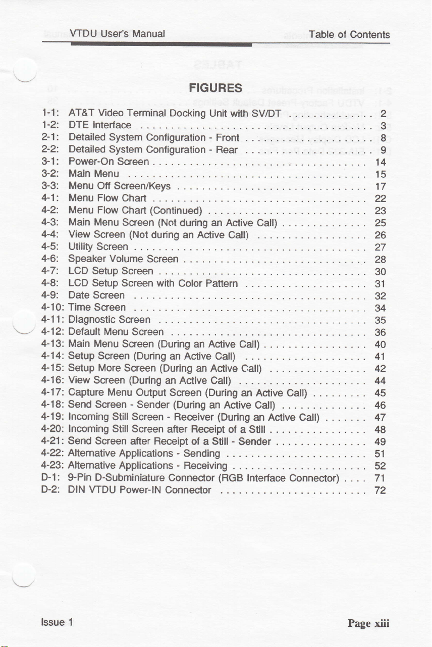
1-1:
1-2:
2-1: Detailed
2-2: Detailed
3-1: Power-On
3-2: Main Menu
3-3:
4-1:
4-2:
4-3: Main
4-4: View
4-5:
4-6:.
4-7:
4-8:
4-9:
4-10: Time
4-1 1 : Diagnostlc
\'----
4-12: Default
4-13: Main
4-14:
4-15: Setup
4-16: View
4-17:
4-18: Send
4-19: lncoming
4-20: lncoming
4-21:
4-2.: Allemative
4-23:
D-l:
D-2: DIN VTDU
WDU
AT&T
DTE
Menu
Menu
Menu Flow
Utility
Speaker Volume
LCD
LCD
Date
Setup Screen
Capture Menu
Use/s Manual
Video Terminal
lnterlace
System
System
Configuration - Front
Configuration - Rear
Screen
Ofl ScreerVKeys
Flow
Ghart .
(Continued)
Chart
Menu
Screen
Screen
(Not
during
Screen . . . .
Screen
Setup Screen
Setup Screen with
Screen
Screen
Screen
Menu
Screen . . .
Menu
Screen
(During
More
Screen
Screen
Sseen
(During
Output
-
Sender
StillScreen
Stil!
Screen
Send
Screen after Receipt
Applications
Altemative
Applications
$Pin D-Subminiature
Power-lN
FIGURES
Docking
(Not
during an Active
Active
an
Pattern
Color
(During
(During
an
Active
an
an
an Active Calt)
Screen
(During
-
atter Receipt
Connector
Connector
(During
Receiver
ol
a Still - Sender
-
Sending
-
Receiving
Unit with
Call)
Active
an Active
Call)
Active
(During
of a Still
(RGB
Catt) .
Call)
an
.
SV/DT
.
Call)
Active
Catt)
Calt) .
an Active Catt) .
lnterface
Connector) . . . .
Table
.
of Contents
2
3
8
I
14
15
17
22
23
25
26
27
28
30
31
32
u
35
36
40
41
42
44
45
46
47
I
49
51
52
7'.|
72
lssue 1
Page xiii
Page 15
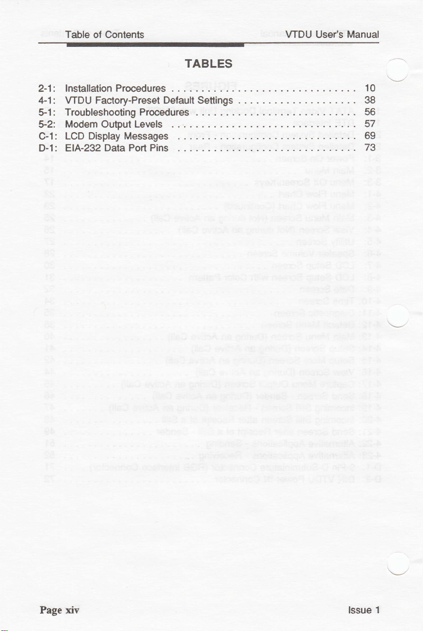
Table of Contents
WDU User's Manual
TABLES
2-1:
4-1:
VTDU Faaory-Preset
Troubleshooting Procedures . .
$1:
*2:
Modem
Output Levels
Gl:
EIA-232 Data Port Pins
D-l:
Default
Settings
10
38
56
57
69
73
xiv lssue 1
Page
Page 16
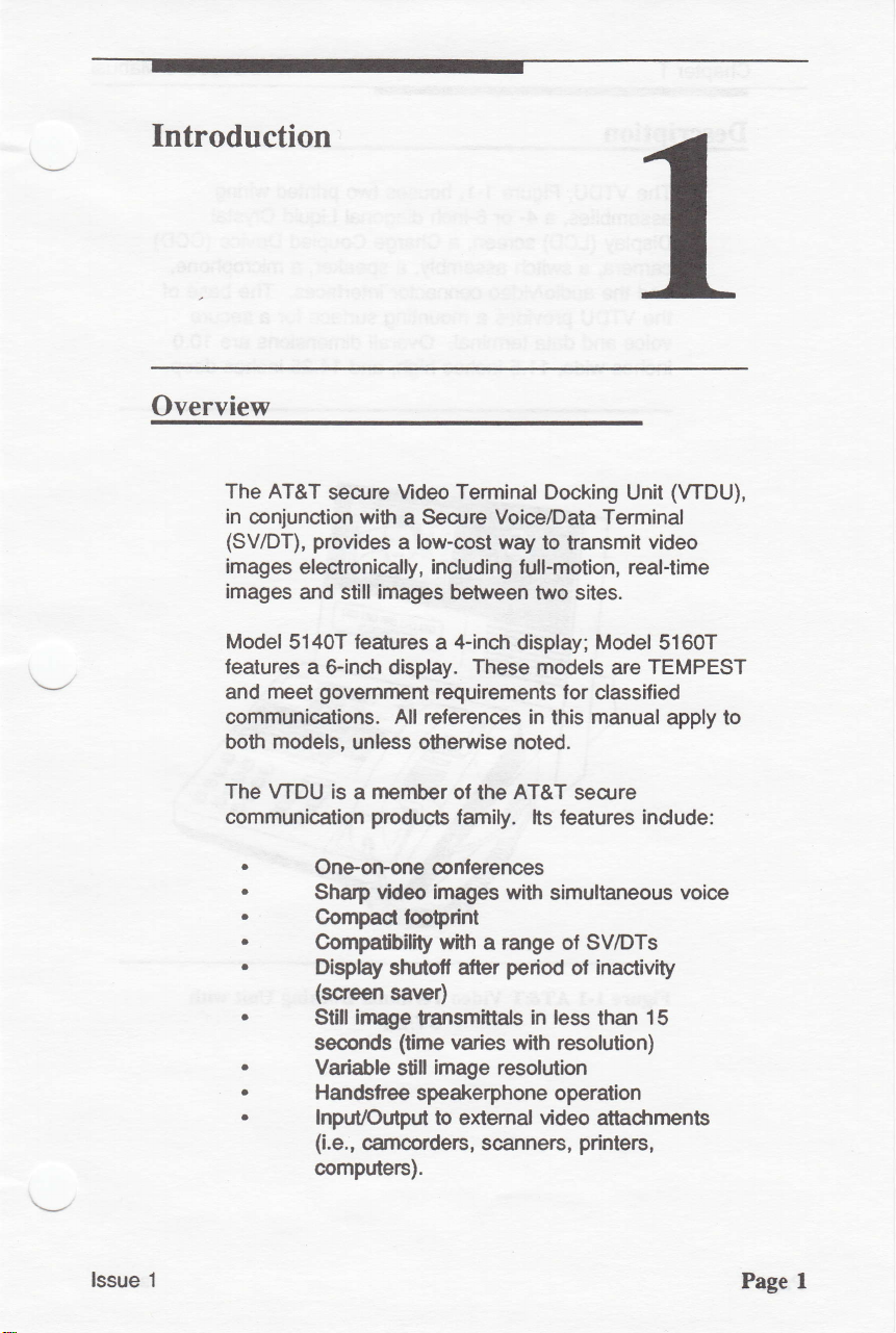
Introduction
Overview
The AT&T
in conjunction
(SV/DT),
images
images
Model
leatures
and
communications. All references in
both
The WDU is
communication
.
.
.
.
.
.
.
.
.
secure
with
provides
electronically, including full-motion, real-time
and stifl images
5140T features
a
Sincfi
govemment
rneet
models,
Oneomone
Shatp video images with
Compact tooprint
Compalibility wtth
Dasplay
(screen
Still irnage
seoonds
Variable
HanGlree
lnpuUOutput
(i.e.,
computers).
display. These modeis
unless
member
a
producB
shutotl
saver)
camcorders, scanners,
Terminal
Mdeo
a Seqrre
low-cost
a
othemise noted.
Voie/Data Terminal
way
between two sites.
4-inch
a
requirements for
display;
of the AT&T
family. lts features indude:
conferences
a range ol SV/DTs
period
atter
tansmittals
(time
varies with resolution)
stillimage
speakerphone operation
to extemal
in less
resolution
Docking
to transmit
this
simultaneous
video
Unit
Model
are
dassified
manual
secure
inactivity
of
than
attacfirnents
printerc,
(WDU),
video
51607
TEMPEST
apply to
voice
15
lssue 1
Page 1
Page 17
Chapter 1
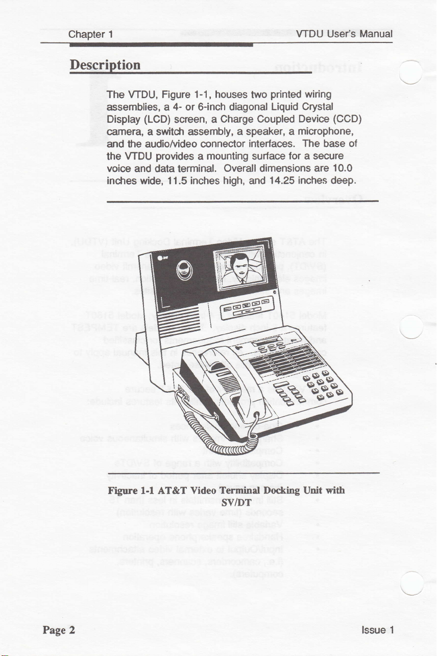
Description
WDU Usefs Manual
The WDU, Figure
assemblies, a
Display
carnera,
and
the
voice
incfres wide, 11.5 inches
(LCD)
a switcfr
the
audiofuideo cennector
WDU
provides
and data terminal.
1-1, houses
4- or
6-inch
screen,
a
assembly, a speaker,
mounting surface
a
printed
two
diagonal
Charge Coupled
Overall
high,
Liquid Crystal
a
interfaces.
lor a secure
dimensions
14.25
and
wiring
base
are
(CCD)
10.0
deep.
Device
microphone,
The
inches
of
Page 2
Figure 1-l AT&T Video
:6"j8
Terminel Docking Unit
SV/DT
with
lssue 1
Page 18
VTDU
Usefs
Manual
Phvsical Interfaces
Chapter 1
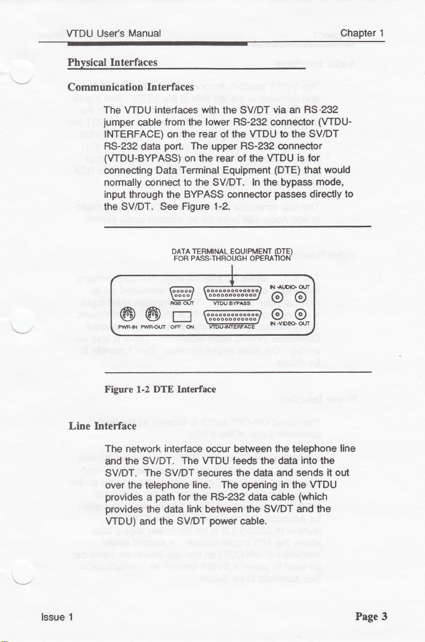
Communication
The WDU interlaces
jumper
INTERFACE) on the
RS-232 data
(WDU-BYPASS)
connecting
normally
input
through the
SV/DT. See
the
99*o-
Interfaces
with
the
from
cable
port.
Data Terminal Equipment
connect to
DATA
FOR PASS.THBOT'GH OPEMIION
Goood foooooooooooool
looool \oooooooooooo,
RGBOUT
lower
the
rear
of the
The
upper
on the
BYPASS
Figure 1-2.
rear
the SV/DT. In the bypass
connector
TERMML
WIX'BYPASS
-
-
SV/DT
RS-232 connector
via an
WDU to the SV/DT
RS-232 @nnector
of the
EOUIruENT
VTDU
is lor
(DTE)
passes
(DTE)
oo
9"*g
RS.232
(VTDU-
would
that
mode,
directly
to
Line Interface
1
lssue
Figure
The network interlace occur between the telePhone
and
SV/DT.
over the telephone
provides
provides
VTDU) and the
1-2 DTE Interfrce
tle SV/DT.
The SV/DT secures the data
The WDU
line. The
path
a
the
lor the R$232 data cable
link
data
between the SV/DT
SV/DT
power
leeds
opening
cable.
the data
and sends
in
the
into
the
WDU
(which
and the
it out
line
Page 3
Page 19
Chapter'l
Audio Interfaces
WDU
Use/s Manual
The
SV/DT
and connects to
2-2.
Since the
secure data mode, the
not
operational during
voice
operation
jumper
connector.
and
jac*
Audio
phono
The rear
!n
Video Interfaces
The WDU
multimedia
elitemal
and output @nnectors are
These interfaces meet National Television Standard
Committee
analog
for
detaib.
handset disconnects
left
the
side of
WDU operates with the SV/DT
voice
video
a
independent
interfaces
cable
The
audio
interface.
cunector
Out
allows
@mpulers, etc.,
video interlaces. The
(NTSC)
RGB video
audio
inpuUouput connector
panelol
for an external audio system.
iacks
for
extemal
video
standards.
output
interface.
from
WDU. See Figure
the
functions
To
call.
ol
WDU,
the
to the SV/DT
WDU
the
mics, monitors,
to
be connected
composite
phono
RCA
There is also an
See Appendix D
SV/DT base
the
in
the
ol the SV/DT are
enable
contains
jack
SV/DT
handset
a
handset
is
RCA
a
Audio
printers,
via its
video input
interfaces.
Power Interface
Page 4
power
The
connector
A female
@nnector
low-vohage
supply
30L3,
ON-OFF swiich
panel
of the
power
(Recognized
manufactured
panel,
power
@nnector
accepts
cord coming
lor Advanced Power
number
above the
connector
be used to
See Appendix D
(KS23821-LS)
APS model number. A
(PWR-OUT)
power
a SV/DT through an
for
is located
olr the
WDU.
(PWR-|N),
power
Component Model:
Hitron Electronics Corporation
by
SoluUons).
is on the
on
details.
the
rear
also on the
from
the
from
the external
The AT&T
power
supply
second
@nnector
interface
plug-ended
APS4OES-
part
power
rear
label
panel
cable.
rear
power
can
lssue 1
Page 20
VTDU
User's
Manual
Chapter 1
/N
r\
sA't966
WARNING
as input
is
not rated for
power
Both
connector.
is rated lor
AT&T
VTDU
Gommunications
Belore
lN
connector
OFF/ON
Internal Video
Camera
The
upper
integrated
Display
NOTE:
power
supplies
The
the WDU.
STU lll
without
connecting
switch ol the
Devices
display
custom camera and lens assembly.
Never
for the WDU.
use
power
units to the
approval
Customer Service Center.
the
ol the
install
a STU-lll
The
as the
power
have
the same
supply fumished with
Do
not
add
PWB-OIJT
of
the AT&T Secure
power
supply cable to the
WDU, make
WDU is in
housing
contains a color CCD
STU
supply
peripherals
sure that the
the
Power
power
lor
the WDU.
power-out
the
connector of
power
position.
OFF
Suppty
suppty
VTDU
or non-
the
PWR-
The
upper display
display mounted next
horizontal viewing
viewing
VTDU is
diagonal
angle ol
available
color
Operation of the VTDU
The VTDU
displayed on the LCD screen that
lunction keys
system
a
When
the
Chapters
the
lssue 1
is
volume
the
lunctions
menu
housing
angle
+10
with
LCD
display.
operates
below the screen. When
deactivated, the live
roc*er key
menu
system
displayed
4
3 and
system and the
explain the
also contains a color LCD
to the camera. The
of
+i-45 degrees and
degrees,
either a
primary
provide
through a menu
their
is
active,
on
the bottom ol
panel
-30
degrees. The
4-inch
or
utilizes the
the
panel
lunction keys
labeled functions.
keys
these
lunction
and operation
keys.
display
a &inch
system
five
menu
assume
LCD
screen.
vertica!
a
has
panel
and
ol
a
Page
5
Page 21
Chapter
1
A
scteen saver blanks
inactivity.
activates
Any keystroke
tre iispiay screen.
the
display
or incoming
aller
call
VTDU
Use/s
2 minutes
immediatety
Manual
of
\--l
Page
6
lssue 1
Page 22
Installation
Introduction
This
chapter
VTDU, whictr is
the
SV/DTs. Please read
you
begin the
lnstalling the VTDU
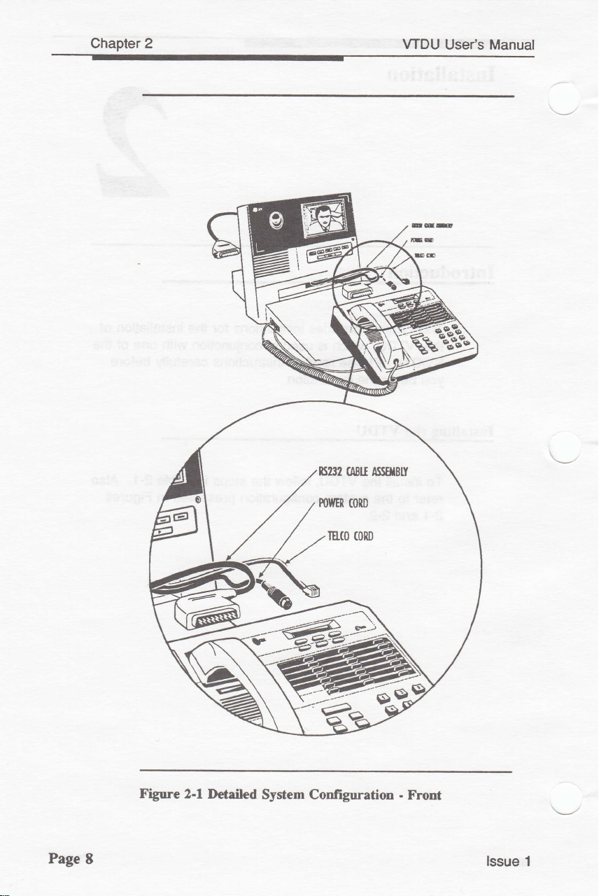
To installlhe WDU, follow
reler
to
the system configuration
2-1
and
2-2.
provides
installation.
instuctions lor
in
used
conjunction
allinstruc'tions
the steps
installation
the
with
one of the
carefully before
in Table 2-1. Also
presented
in Figures
ol
lssue 1
Page 7
Page 23
Chapter 2
WDU
il0
\UC
Use/s Manual
lET
Page
7'-)ry.r*
Ftgure
8
2-1 Detailed
System Configuration
.
trtont
lssue
1
Page 24
VTDU
Use/s Manual
Chapter
2
TELCO CONNECTOB
TELCO CABLE,
VTDU
POWER
SUPPLY
(KS23821-U')
Do .rd itdrl
r ScrD Voior/Drlr
lq
lhc WDu. Tb VTDU
Fnr
VIDEO TEnil[ifAL.'
WARNINGI
Th.
SV/DT
eppty lor ib
Fr.
\
RS-232 CABTE
|
CONNECTOR
(SV/DT)
loid
Pfir Srpply b mdrd 1.EE WITH
parr
erpply a nd r-d to.
(KS2321.L3)
^*o"/"*
g+Cy
Por
Wot .
SECURE Vo|CEDATA
TERMINAL
q
r iprr
u- r ttr
(SV/DT)
POWER IN
HANDSET
CORD
/
lssue
-AUDIO.
IN
VTUJ
RGB OUT
@@n@@@
pWB-tN
pwR^6UT
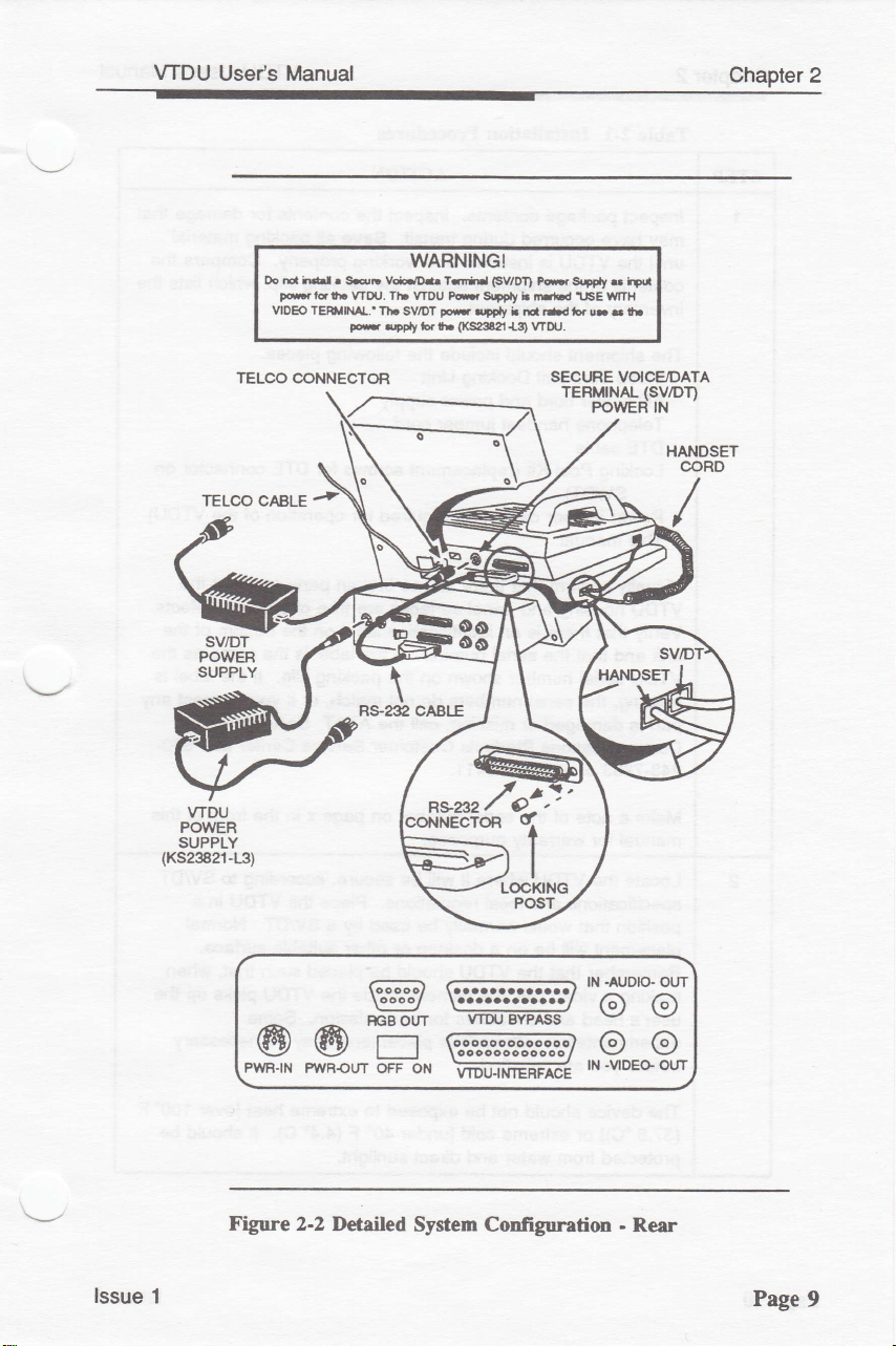
Figure 2-2
1
orr
Detailed
OH
System Configuration
BYPASS
lN
@@
.VIDEG
-
Rear
OUT
OUT
Page
9
Page 25
Chapter 2
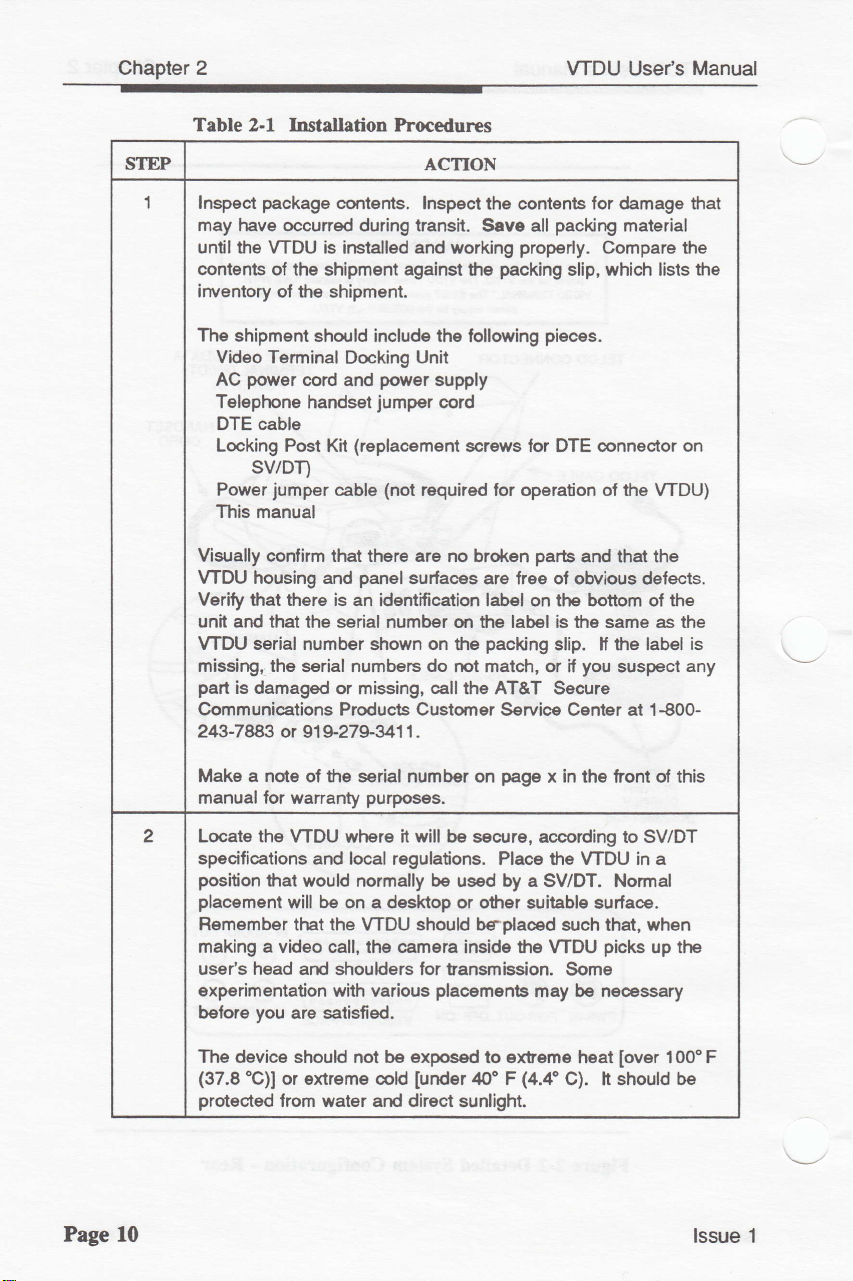
Table 2-l l$tallation hocedures
WDU Useds
Manual
STEP
1 lnspect
may have occuned during transit.
untilthe WDU is
contents
irwentory
The
Visually confirm that there are
WDU housing and
Verify that there is an
unit and that
WDU serial
missirg, the
part
Communications Products Gustorner
243-783
package
ol the shipment
shipment shorld include the
Video Terminal
power
AC
Telephone handset
DTE cable
Locking Post Kit
conterils. lnspect
irstallEd
of the shipment.
Docking
cord and
power
jumper
(replacement
against
sv/DT)
jumper
Power
This
manual
is damaged
the serial number on the label is lhe same as the
number sfrown
serial numbers
or 91 9-279341 1 .
(not
cable
panel
surlaces are free of obvious defects.
identification label on the bottom ol the
or missing,
ACTION
the contents
Save all
and
working
Unit
supply
cord
required lor operation of the WDU)
no broken
on
the
do
not match, or il
call
properly.
packing
the
following
screws
the AT&T Secure
for
packing
Service Center at 1€00-
for damage that
packing
pieces.
DTE @nnector on
parts
material
Compare
slip, which lists the
and that the
slip. if the label
you
suspect
the
is
any
Page l0
Make a note of the serial number
manual lor wananty
2 Locate the
specifications
position
placement
Remember that the
making a video
user's head
experimentation with various
before
The device should
(37.8
protected
WDU where it
and local regulations. Place
that wouH normally be used by a
will be on a desktop or other
call, the camera inside the WDU
and shouHers for tansmission.
you
are satisfied.
.C)]
or
extreme
from
water
purposes.
WDU
be exposed
not
cold
and direct
page
on
will
be secure, according to SV/DT
in
x
the front ol this
the WDU
SV/DT. Normal
suitable surface.
should
[under
beplaoed such that, when
Some
placements
to extreme heat
/m'
F
sunlight.
be
may
(4.4'C).
picks
necessary
h should
in
[over
a
up the
100'F
be
lssue 1
Page 26

VTDU User's Manual
Chapter 2
STEP
3
Follow these steps to installthe
Unplug
disconnect
Unplug
DTE
4 Remove
connector
similar tool.
(locking post
5
Connect
connestor on the
angled
slide the latch
6 Place the
space at the
through
the
the openirB
port (lower
the SV/DT
the cord between the
the telephone line cord frorn ihe SV/DT. Remove the
connection
the hex screws on the rear ol the SV/DT DTE
(see
Figure 2-2) with a 3/1&inch
Replace the
kit) supplied with the WDU.
the DTE cable supplied wiih
connector to the data
to secure
SV/DT on the
rear of the SV/DT to
the opening in the WDU. While
platlorm,
push
in the WDU, and connect it to the WDU lnterlace
R9232 conneclor) on the back ol
7 Reconnect the SV/DT
from
WDU
connector.
the rear and
ACTION
wlth a SV/DT.
WDU
power
unil from the wall
the SV/DT, if used.
from
hex
SV/DT.
Make sure
the
power
screws
jack
on the rear ol the SV/DT,
cable.
outlet,
and
supply and the SV/DT.
hex
driver or
with the n€w screws
lhe
you
to the DTE
WDU
@nnect the 90%-
base of the WDU, allowing enough
connect and leed
placing
the
thE SV/DT on
the oher end of the DTE @nnector through
the
WDU
porer
cable by leeding it through the
plugging
it into
the
SV/DT
power
a
and
cables
.
lssue 1
I Reconnect the telephone line cord
WDU from
I
Center
as
lar
10 Disconnest the SV/DT handset cord from the SV/DT base. Plug
the rEar
the SV/DT on the WDU base, and
it will
go
as
the handset cord
the WDU.
11 Using the handsat
one end of the
(See
jumper
base and the other
12
13
lett side
ll
port),
Figure 2-2.1
Reconnect
of the WDU.
you
had
a device connected to the SV/DT
reconnec't this device to the WDU Bypass
the SV/DT to the
plugging
and
against the VTDU without forcing it.
into the rearmost
Figure 2-2.)
jumper
cord supplied with the VTDU, connect
cord
into
end
(See
by feeding
it into
line
the handset
irilo
remaining handset
the
Figure 2-2.)
power
sour@. Wait for the SV/DT
h through the
the SV/DT
slide
jack
on the
jack
R$232
jack.
line
the SV/DT back
side
lett
on the SV/DT
jad<
port
ol
m the
(DTE
port. (See
to complete iB self test.
Page 11
Page 27
Chapter
2
VTDU
User's Manual
STEP
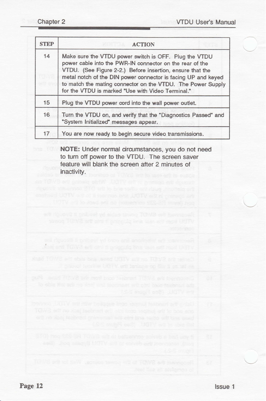
14
15 Plug
16
17 You
NOTE:
to tum ofl
leature will
inactivity.
Make sure the
power
cable into the PWR-IN
WDU.
metal notch
to match
for the
Turn the
'System
(See
of the DIN
lhe mating
VTDU is marked
the WDU
WDU on, ard verity
Initializecf
are now ready
Under
power
blank the screen atter 2 minutes
ACTION
power
WDU
Figure 2-2.) Before
connec'tor
power
msssagss
to begin
nornal
to the
suitch is OFF. Plug the WDU
@nnector on the rear
power
oonnector
on
with
"Use
cord into the wall
that the 'Diagnostics Passed" and
appsar.
secure
circumstances,
WDU.
of the
insertion,
the WDU. The Power
Video Terminal.'
video trarsmissions.
The
ensure
is facing UP and keyed
power
you
outlet.
not need
do
that the
screen saver
o,
Supply
Page tL
lssue 1
Page 28
Setup and
Initial Operation
The WDU is
for
various
conditions
WDU is installed and tumed on,
the
shipped
options.
the terminal
vldeo calls wlthout dolng
VTDU
ahrays comes up
modes
menu. You
the course of a
changes using the
be
using the
settings and cpme up
and back on.
date and time
will NOT have
A
to
feature-set
messages reliably
Upon
Diagnostics
can be changed easily, using the
can change these
losl
at the end of
DEFAULT menu
You must
referencing. lf
to
power-on
the
diagnostic
VTDU. The
controller
successful completion ol this test,
Pass'
lnitialized'to indicate
Feature Set Version
Codec on the
ACodec Version also display.
on the scfeen
3-1); then the
Figure
3-2).
left
lor
scteen
from
the
Default
assumes upon
any
in
the default
video
call, but unless
DEFAULT
the call.
become
whenever the
use the UTIL]TY
reset the date and time.
executes
power-on
performs
to the user through
displays,
(FSV),
and
approximately
followed
that the system
VCodec Version
Slave
reverts
lactory with defaults set
those
settings
menu,
the unit
diagnostic
are
power
you
other setup.
modes,
settings
Any
manually
you
the changes
settings changed
the'nef
WDU is
loses
power
when
verifies
conectly
and can convey
up.
lnltlate
can
The
but these
UTILITY
save the
default
tumed off
menu
to set
power, you
is
applied
that the
the LCD screen.
'Power
On
by'System
is operable. The
(Master
Codec
on the
right),
The information remains
3 seconds
to the
Main Menu
(see
(see
Once
during
will
.
and
Figure
lssue 1 Page 13
Page 29
Chapter 3
VTDU User's Manual
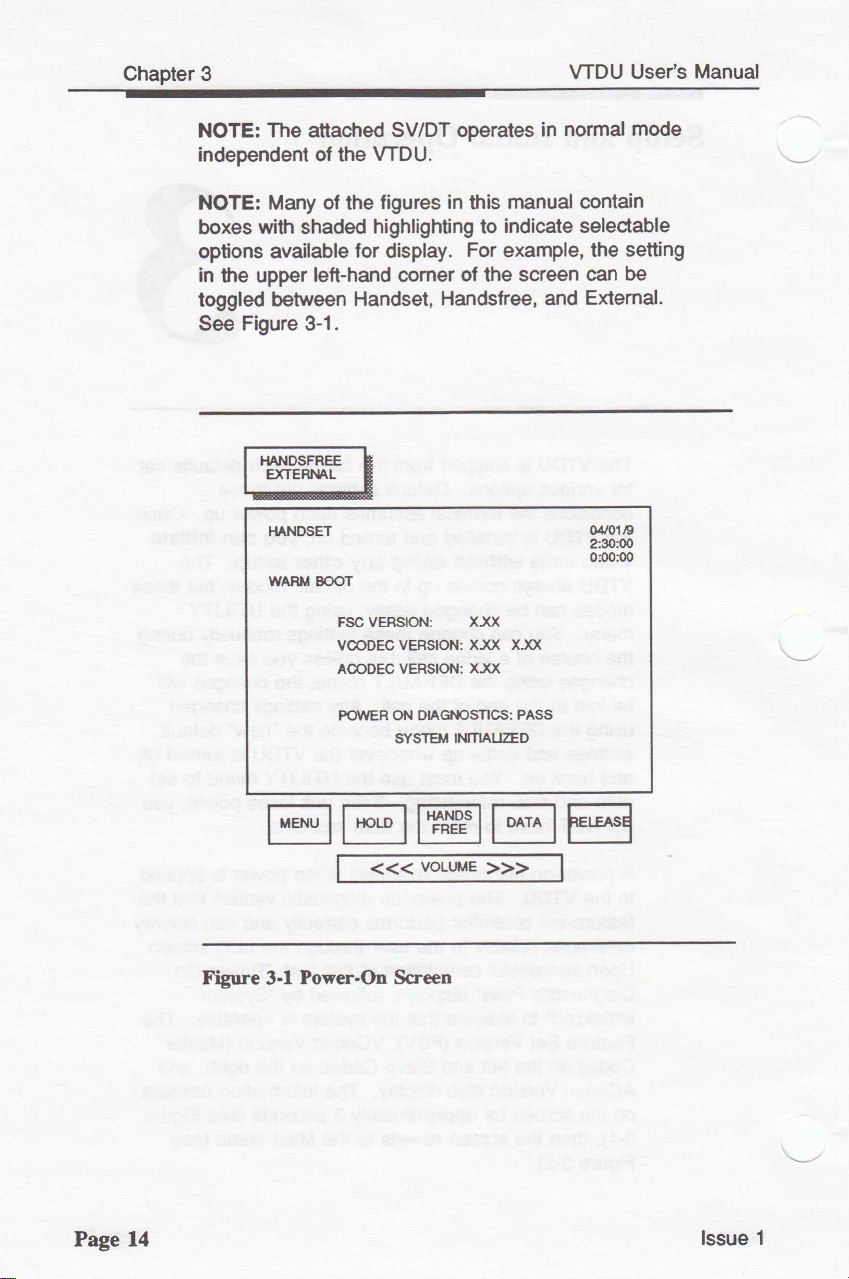
NOTE: The attacfied SV/DT operates
independent of the
NOTE: Many
with
boxes
shaded
options available
in
upper
the
toggled
See
between Handset,
Figure
3-1.
}IANDSET
WARII BOOT
WDU.
ligures in
of
the
highlighting to
for display.
lett-hand cpmer ol the
FSCVEBSON:
VCODECVERSION:
A@DEC VERSION:
this
For
Handsfree, and
XXX
XXX XJO(
X)fi
manual contain
indicate selectable
example,
screen can
in normal
the setting
Extemal.
04101
2:30:00
0f0:00
mode
be
/9
Page 14
Figure
FO,VER ON DIAGI.IOSTICS:
INITI/AI
SYSTEM
PASS
I''FD
@E@EE
Power-On Screen
3.1
<<<
voLtME
>>>
lssue 1
Page 30
VTDU
User's
Manual
rLtrrE
rT@EE
voltME
<<<
>>>
TIME DISPLAY
ts oPTToNAL
I
04r!119
23000
0s000
Chapter
3
Figure
Secure Voice Data
Before
remote
SV/DT. Set
follows:
as
1.
2. ENABLE TRELLIS
NOTE: Refer
datra oommunication operation.
lssue 1
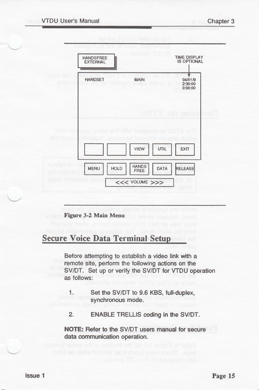
Main Menu
3.2
attempting
perlorm
site,
up or
Set
the SV/DT to 9.6
synchronous
to the SV/DT
Terminal
to establish a
following
the
verify
the SV/DT lor WDU operation
mode.
coding
users
Setup
video
actions
KBS,
full-duplex,
in
manual lor
link
the
with
on
the
SV/DT.
secure
a
Page 15
Page 31

Chapter
3
VTDU Use/s Manual
3.
NOTE: The receiving
be set up
SV/DT.
Operating
The WDU is
which
LCD
IMPORTANT: When
lcons,
of the lcons; otherwlse,
keep
When the system
Menu displays on the
keys
from
function
the
pane!
For
information, refer
SV/DT
other
all
manual.
in
the same
SV/DT
end SV/DT of a
tnanner
the VTDU
equipped
take on ditferent
screen display.
with five
funclions,
the LCD
panel
the
thelr labeled
on
take
Main Menu. The following
the
keys.
lunctlon keys take on the ldentity
ldentity.
is initially
LCD
labeled
own
their
and operation
set up
to
the appropriate
video
as
transmitting
the
paneltunction
depending upon the
screen
panel
the
powered
screen. The
identty when
of
the menu system
lunction keys
up, the
paragraphs
call must
keys
dlsplays
Main
panelfunction
you
exit
explain
and
Remember,
data terminal does not compromise
SV/DT. You can still operate
the
mode
Atso remember
teature
Panel Key Functions
Reler
keys.
are displayed on the
Page 16
the WDU to
were
that the
not
WDU has
as
attaching
if
the
WDU
to blank the sseen during
Figure
to
These
for
3-3
keys function
the location
LCD
as
screen.
the secure
the capabilities ol
the SV/DT
attached.
a screen saver
periods
panel
of the
labeled when
voice/
in normal
inactivity.
of
no icons
function
lssue 1
Page 32

VTDU
Usefs Manual Ghapter
3
NOTE: When
video
call, atler
screen turns otf
remains
the
HA}.IDSFREE
EXTERML
I.I,ANDSET
on. Depressing
LCD
screen.
NOTE: ll
lhe rnenu
e'livate the
th€
the system
2 minutes
(as
a screen saver)
is
scre€n
is deared,
on-scrs€n meru,
pess
any
dark
the MENU
is
not
of user
panelkey
(screen
engaged
inactivity,
while
TIME DISPI-AY
1S OPTIONAL
or
saver)
h.rtton to
in
an active
LCD
the
VTDU
the
re-illuminates
I
o4to1t9
230:OO
O:00:OO
rr@rEtr
voLUME
<<<
Figure
lssue
1 Page 17
3-3
Menu
Off Screen/Keys
>>>
Page 33

Chapter 3
Menu Kev
Depressing the
screen
function
above each
this
the
screen, and the
labeled
Key
Hold
Menu key
on the LCD display.
labeled on the
as
key. The lollowing
more
in
Main Menu
detail.
mode removes
keys on the
(see
Figure 3-1 and
activates
The five
LCD
screen
paragraphs
Depressing the
the
panel
3-2).
VTDU
Menu
Main
the
panel
keys
immediately
describe
EXIT key
menu from the
while in
shallfunction
User's
as
Manual
Hands
Data
Depressing the
displays
both
time
The
communication
a HOLD
WDUs untilthe
by the
communicating
Hold key blanks the
Inessage, and suspends
initiator of
VTDU will not be
untilthe
Free Kev
The Hands Free toggle
callto the SV/DT
a
internal speakerphone and
or
an extemal audio system
lo
in
displayed
Bypass Kev
The Bypass
machines,
directly
Bypass
convenience of
from
the
the upper
mode
personal
to
the data
port.
SV/DT when cpnnecting
handset
allows
computers, etc.)
port
ln effect, this
not
having to disconnect
the SVIDT.
video screen,
key is
Hold
HOLD.
the
HOLD is removed.
key directs the audio
left comer ol the screen.
depressed
(HANDSET),
microphone
(EXTERNAL),
able
to the
(HANDSFREE),
extemaldevices
to be connecled
via
allows
the
the user the
the
of the SV/DT
leature
pedpheral
the audio
a second
resume
to
portion
VTDU
as
(e.g.,lax
VTDU
WDU
devices to
on
of
Page 18
Data key, when
The
Bypass
the
rnode,
depressed,
allowing
toggles the
the flow of RS-232 signals
VTDU into
lssue 1
Page 34

VTDU
Usefs
Manual
lrom
the SV/DT directly
port
on the
display.
The
Bypass mode must
Data
key
WDU
before
call. Depressing
interface
to make
to
and
and causes
be
adivated by depressing
initiating
or receiMng
the Data key
receive
or
from
BYPASS message
a
again
next
the
VTDU Bypass
the
a Secure Data
restores
call.
Chapter
to
the
the video
3
Othenrise,
Secure Data
over
the
NOTE:
Bypass
Release Key
The
Release key
Volume Kev
The Volume
handset
or
graph
bar
the direction
To Initiate
To initiate
SV/DT
through the SV/DT. Once
made,
SV/DT to
depressing the Data
cal! @uses
video
signal.
Video
communication is not
mode.
terminates a
roc*er key increases
volume,
displays for
and
depending on which is
levelot volume
a Video Call
video
a
set up, one
simply
establish a
call after WDU installation
can
press
the
video
key
during
"lnvalid
approximately
begin
SECURE
Key"
to
possible
video
call.
or
decreases speaker
1
second,
change.
making
by
the audio connection is
DATA
link
an
active
display in red
in
the
active.
a voice
button on the
A
showing
and
call
lssue 1
The WDU
full
duplex,
and at 2.4 KBS
only
coverage
KBS.
(no
will
synchronous
voice).
and
operate at
full duplex,
These
provide
still
lower
mode for
syncironous
options
picture
frame rates
voice
both
mode
expand
network
transmission
4.8 KBS
at
and
for video
ai2.4
video
Page 19
Page 35

Chapter
3
VTDU
User's Manual
Consider
establish
red
asterisks
display
during a
reducing
video link
a
in
the
video call.
the data rates when
or when
upper
you
lett-hand
notice
comer
it is
difficuh to
numerous
of the
\
\-l
Page 20
lssue 1
Page 36

Operation
Introduction
This
chapter
explains the
following.
.
.
.
.
.
Menus
VTDU
Menu
call
Menu
Tips
enhance a video
Procedures for
Menu Fulctions
The menu
the available WDU features.
panel
the
display s6een and change funstion
change. The Menu Flow Charts, Figures
summarize
paragraphs
display
system
keys
are defined by
the available
in
detail.
menu
and
options available when not in a video
options available
for
using the
provides
describe each
options
various
call
transmitting
the
icons
menu features.
menu
available on the
when
menu
still
user a screen display ol
ln Menu mode,
across
and
the associated
in a video
functions to
video
the bottom
as
the
4-1
The lollowing
call
pictures
five
the
menus
4-2,
and
of
lssue 1
Page
21
Page 37

Chapter
4
VTDU
Useds Manual
SETUP/DEFAULT
IENUS
(PHONE
oD{+rooK)
EML]T
innfr
tftrE
EEEffE$is*
PA.IEL
KEYS TAKE ON FUI{CNON
NOTE: lf the
ilENUS AFTER ESTABUSHTT{G
screen
MENU key to
*nffir:
EgE
LOIw/UED'
HlGIU
frmm
"[*'*lE
SUPER
OF ONSCBEEN
is dad<
aclivale
A VTDEO CALL
MENU
(screen
saver),
lhe
on-screen npru.
(SEGURE
t4r
El,*,
o"
I
ilffi*ffi
ABOVE KEY
press
the
DATA)
I
I-l EHJHlt'*,
Page 22
To
select HANDS FREE, HANDSET,
after call
setup,
you
MUST
exit
oT EXTERNAL VOICE
from
the Main Menu.
EEEfEESH*
Panel keys
Menu; on-screen menus will rpt b€ available until
crll wlll
tlElll, !. Dnroycd Rder lo th€
take
bc
droppcd lf
Figure 4-l
on namEd tunction when
you prrsr
Menu Flow
thc RELEASE loy eltcr'rcrun
VTDU
Chart
is
EXIT
User's
Manuril lor ddails.
selected ftom Main
MENU is
pushed.
Thc
lssue 1
Page 38

VTDU
User's
Manual
Chapter 4
IIENI.'S TO
SEND STILL
rtftEtl
o
N
S
EEEE
c
R
E
E
N
M
E
N
U
S
mmffiE
EE@E
IIENT'S
HM
ON VTDU BECEIVING
ITAGES
EJl
El
E]
El
EJ
SNLL MAGES
iffiErtrE
fir:rtrt
!EErE@
EEI
TRAi}SMISS|ON
COf,IPIETE
TMNSUTSSION
STJEMENU
TMt,lsutsstoN
SEI{D MENU
STII.L IMAGE
CAPTURE
MENU
ON.SCREEN
MAN MENU
RSEPTION
COUPLETE
SNII MAGE
RECEIVING
SLBUENU
ON-SCREEN
MAN
MENU
lssue 1
Figure 4-2
Menu Flow
Chart
(Continued)
Page 23
Page 39

Chapter
4 VTDU
User's Manual
Before
an Active
The WDU
can
settings,
your
you
lf
settlngs,
leam
video
you
ll
settlngs,
select the intemal
funstions,
and sei
Main Menu
When
screen displays after
inactive Main-Menu
is
not in
Call
@mes with factory-set
immediately
or
liking.
choose
tum to Durlng an Actlve
how
call.
wlsh
the following
select diagnostics,
the
the
an active video
initiate video
you
can customize
to use the
to use the WDU
to customlze
or elitemal camera,
date
and time.
WDU
is
tumed on, lhe
self test
also displays
default settings.
calls
the
factory-set
these delault
using
delault settings
delault
Call on
screens available during a
your
WDU
paragraphs
adjust
(see
call.
delault
explain
LCD
set
volume
inactive Main
Figure 4-3).
whenever
page
how
lo
settings,
The
WDU
the
You
to
39 to
Menu
\-/
Page
The inactive Main
selections:
disables
menu key
Figure
an aclive video
Main Menu
VIEW:
UTIL:
EXIT:
24
Menu
VIEW,
the
labels from
zt-3
shows the Main Menu
Settings
Depressing
This
Depressing
allows for revierv
Depressing
UTIL, and
menu func{ion
call.
key is not
clntains three menu
EXIT.
keys and removes
the
screen.
key
this
available
key
this
or ctanges
key
this
The EXIT key
screen
selecb
during an active call.
selects
tums
the
when
Mew
the
the Utility
to the
default settings.
Main Menu
the
not in
(Capture)
Menu
OFF.
Men
and
\_--.,
lssue 1
Page 40

WDU
Use/s Manual
Chapter 4
The Main Menu keys
indude:
Proceed
Proceed
Turn Menu
to View Menu
to Utility
Menu
Otf
EETTE
available
before an active call
VIEW
UTIL
EXIT
OISPTAY
TIME
lS
OPTIOI.IAL
I
04J!1/9
2:30O0
00000
lssue 1
View
rr@rr
Figure
Menu
The View Menu
intemal
active
intemal
4.3
Main Menu
eamera
call, the
and extemal c€rrneras.
voLtfiE
<<<
Screen
screen allows the user to
or an extemal camera.
VIEW
screen
CaII)
>>>
(Not
during an
provides
See
Figure 4-4.
Active
view
While not in
preview
a
an
of
an
the
Page 25
Page 41

Chapter 4
The View Menu keys indude:
Select View Source
lntemalCamera
Extemal Camera
Retum
Reeive Communicating
Main Menu
to
and
t-*", h
L*r*#
WDU
VTDU
TIME DISP|IY
Use/s
CAM 1
CAM 2
EXIT
ISOPT]oNAL
I
04rc119
2:3000
0so$o
Manual
Page
UtilitY
26
r
T]E[]E
EgT@EE
Figure
Menu
The
Menu when an
The
seleot the desired
Utility
Volurne
Diagnosii;and
4-4 View
Menu is
Utility
Menu uses a cpmbination
Utility
Menu
allows access
(speakerphone/handset);
voLurE
<<<
Screen
active
default. See
(Not
activated
video call
from
utility
>>>
during an
from
is not
displayed list.
the
following
to the
Figure
Ac'tive
the inactive
taking
of func'tion
LCD; Date; Time;
Call)
Main
plae.
keys
The
menus:
4-5.
to
\---l
lssue 1
Page 42

VTDU
Use/s
Manual
The
Utility Menu options include:
Move
lndicator
Move lndicator Down
Proceed
Retum
to
Up
to Selected
Main
Menu
Menu
Chapter 4
UP
DOWN
ENTER
EXIT
nffiHEE t
I e-rremur- E
l:-J
TTETEE
EgT@EE
Figure +5
Utility
UTIUTY
VOLI.T'E MENU
>
LCD SETUP MENU
MENU
DATE
TIME MENU
OIAG'{OSNC MENU
OEFAULT UENU
vort rE
<<<
Scre€r
>>>
TIME D]SPUY
tSOPTrcNAL
I
0.Y0t19
230$0
0I)01)0
\r_,
lssue
Volume
1
Menu
The Volume
volumes
settings can
video
restored
are
Menu
can be toggled between SPKR
Menu
allows
for
the speaker and
ovenidden
be
call by the
variable
Volurne rocker key.
atter the callterminates. The Volume
key is
you
temporarily during an active
in the
enter
to set separate default
handset.
key
HAND.
and
Delault
Defautt settings
position
volume
and
This center
Page 27
Page 43

Chapter 4
VTDU
Use/s
Manual
toggle key
option
or
decrease the
default
See
The Volume
Decrease
lncrease
Store
Speaker Adjustnent
Handset
Store Delault
Retum
stores the
to the next
setting and
Figure
46.
Menu keys indude:
Speaker
Speaker Volurne
Present
Setting
Adjustnent
Setting and
to Utility
present
selection.
volume. The
retums cpntrolto
Volume
and
Menu
The
Select Function
setting and
arrow
SAVE
key
the Utility
Tt\rE DISPI-AY
advances the
keys increase
I
04,o1/9
2:3OO0
osoo0
the
Menu.
SPKR
HAND
SAVE
stores
!s omoitAl
fina!
Page 28
MIN MAX
l^"E
G
EEETE
@E@EE
voLrrrE
Figure 46
<<<
Speater Volume Screen
>>>
lssue 1
Page 44

VTDU
LCD
Use/s Manual
Setup Menu
Chapter 4
The LCD
(BRGHT)
Menu
Setup
and contrast
screen while viewing
camera.
value
variable key is
toggled
toggle key
setup
stores the
The
arrow
ol the function
in the center key
between
BRGHT
stores the
option to the
final
setting and
See Figure 4-7.
The
LCD
Decrease
lncrease
Present
Store
Brightness
Contrast
Display
Present
Store
Retum
Setected
Color
Menu options include:
Setup
Selected
Function Value
Sefting and Select
Adjustment
Adjustment
Bar Pattern
Setting and
to
Utility
Menu
allows
the
you
(CONTR)
preview
keys increase
selected.
present
next
selection.
Function Value
The LCD Setup Menu
CONTR. This
and
setting and advances
returns
to adjust brightness
the
or
decrease
LCD
SETUP
local
the
and can be
on the
from
position
center
The
SAVE
to the Utility
Function
key
Menu.
BRGHT
CONTR
PATRN
SAVE
the
lssue 1
Page 29
Page 45

Chapter
4
I{ANDSET
,E[IEEEE,EEEE ,
.MIN
LCD SETUP
m
'
VTDU
TIME DISPLAY
ts oPTtoi.lAL
I
0.1,/018
23OiOO
00000
MD('
Use/s Manual
EE
EEE
ET@IuE
voLrjltE
Figure 4-7
When
color swatch
Adjust
by depressing
Depressing
to the
LCD
pattem
the
the
brightness and
the PATRN key
LCD
Setup Menu in
<<<
Setup Screen
(PATRN)
key
displays on the
left
the
and
>>>
is
screen. See Figure 4-8.
contrast to
right
arrow keys.
a second
preview
a
depressed,
the desired
retums
time
mode.
a 3-block
levels
you
Page
30
lssue 1
Page 46

VTDU
Use/s Manual
The
LCD Setup Menu keys
indude:
Chapter
4
Decrease
lncrease
Store
Brightness Adjustment
Contast Adjustnent
Display Color
Store
Retum
Selected
Selected
Present
Present
lo Utility
Function
Function Value
Setting
Bar Pattem
Setting and
and Select
Menu
LCD SETUP
trtrtr
t*
EEETE
Value
Function
TITE DSTI.AY
rs
oPTtol,rAL
(XrOl19
23000
0s000
BRGHT
CONTR
PATRN
SAVE
I
lssue 1
Flgure 4-8 LCD
Date Menu
The
function
center
YEAR. The toggle
advances
rT@EE
voLurE
keys increase or
anow
selected.
key which
the setup option
<<<
Setup Screen
The
toggles through MONTH, DAY,
key
>>>
with
decrease the
selected
stores
the
lo the
Color
variable
present
nefi
Pattern
value of the
appears
setling and
selection.
in
and
the
Page 3I
Page 47

Chapter 4 VTDU
Useds
Manual
Depressing
retums
The
Date Menu
Select
Set Month MONTH
Set Day DAY
Sel
Store
Retum
NOTE: When
date/time information is not lost.
the SAVE
you
to
the
Function
Year YEAR
Present
I.{ANDSET
Setting and
to Utility
power
key
Utility Menu.
options
and Store
include:
Menu
is removed from
DATE O4rO1/9
starts
See
Present
calendar
the
Figure 4-9.
Setting
WDU, the
the
TT'E DISPTAY
IS OPTOT{AL
I
2:3030
0s000
SAVE
and
Page
32
SET CURBE'{T DATE MM/DD/YY
ffi
rE
@rE
rE@EE
voLtlrE
<<<
Figure 4.9 Date
Screen
01 /06/9
>>>
lssue 1
Page 48

VTDU
User's Manual
Time Menu
Chapter 4
The
anow keys
function
selecled.
center key which
SECOND. This
increase
or decrease the
The selected
toggles through
toggle
key stores
and advances the setup option
Set AM and PM
Depressing
you
to the Utility Menu.
the
The Time Menu
Present
Store
Set
Hour
Setting and Select
by soolling
SAVE key starts the dock and
options
through the
See
indude:
Set Minute
Set
Second
Select
Seled
Select the
Store Present
Retum
Glock
the
to Utility
Format
12-Hour Display
24-Hour Display
Setting and
Menu
value of
variable
appears
HOUR, MINUTE, and
present
the
to
next
the
Figure 4-10.
Function
selection.
12-hour mode.
the
in
setting
retums
HOUR
MIN
SEC
1aIHR
24IHR
SAVE
the
lssue 1 Page
33
Page 49

Chapter 4
ThIE
TIME
HHiIM:SS
SEf CURRENT
TtrlE
05:00 :00 PM
ffim
rET@E
ET@TE
<<<
\roLr.irE
>>>
VTDU
DISPITY
IS OPIIONAL
I
04,o1/9
23030
0 0r0
User's
Manual
Page
Figure
Diagnostic
Selec{ a diagnostic test
down
selected diagnostic
cycles the
completes,
that test.
NOTE:
running
34
4-10 fime
Menu
on
the
See
lncoming calls cannot
digital
Screcn
Diagnostics
by depressing
WDU through the
the screen
Figure
loopback.
moving
by
Menu
indicates
4-11.
screen.
the
test.
a
Passllail
be
acoepted
indicator up
the
lnitiate the
RUN key.
As
each test
This
condition
while
or
tor
lssue 1
Page 50

VTDU
Use/s
Manual
Chapter 4
The
Diagnostic
Move lndicator
Move lndicator
Run Diagnostic
Diagnostic STOP
Stop
Retum to Utility
Menu keys inc{ude:
Up UP
Down DOWN
Test lndicated
Menu EXIT
D]AGNOSTICS
ALL TESTS
>
,dEMORY
FEATURE SET
DATA LINK
DIGITAL LOOPBACK
START
TIIE DISPI.AY
1S
OPTIO].IAL
I
(X/OlE
2:30:0O
0:00$0
PASS, FAIL
PASS, FAIL
PASS, FAIL
lssue 1
tqErrr
rr@rE
Figure
voLUME
<<<
4-11 Diagnostic
>>>
Screen
Page 35
Page 51

Chapter
4
Default Menu
VTDU
Use/s Manual
\_,
The
Default
default
desired defauh condition.
available during an aclive
settings are stored
Access Memory
The Delault Menu keys
Move lndicator
Move lndicator Down
Toggle
Function
Retum
HANDSET 04t0119
Menu allows
preferences.
(RAM).
Up
and Save
to Utility
Condition of
Selec{ed
Menu
you
to
setect
The ENTEB key selects the
The Default Menu
video
call.
in
battery-backed-up
Figure 4-12.
See
include:
TltvG
DSPLAY
lS
OPnOML
I
230r00
0$0$o
and enter
All
default
Random
UP
DOWN
ENTER
EXIT
is
not
Page
. AUDIO
PcAtrrEM
INIERFACE
PREV]EW
CLOCK DISPLAY ON
AUOIO
PEruRE
VIDEO PORT Ot.rT EMBLED
HANDSETTYP€ PASSIVE
WINDOW
DISPLAY ON
OUALITY 10
I{ANDSET
cAM 1
ON
EEEEE
Er@rr
voLUlG
36
Figure
<<<
4-Ul Default Menu
>>>
Screen
HANDSFBEE,
CAM 2
OFF
OFF
OFF
1,
3,..., 19,20
a
DISABLED
ACI]VE
+5,
D$ERML
ACTIVE
+12
lssue
1
Page 52

WDU
Use/s
Manual
Chapter
4
Default Menu
Audlo
lnterface:
Camera:
Prcvbw
Wlndow:
Selections
The WDU
upon.receipt
HANDSFREE
Handset
selected, and
microphone
EXTERNAL
Free key on the
between
and the
speaker).
The WDU defaults to
input when CAM
extemal camera
selected.
The WDU
window
screen
preview
video when
defautts
of a call
mode when HANDSET
and
is
HANDSET,
EXTERNAL
delaults
display
when tumed
window
tumed
to
is
selected,
defaults
speaker
selected.
front
1 is
input when CAM
to the
on the active
display during
OFF.
Handsfree
when
defaults
to an exlemal
when
Hands
The
panel
toggles
HANDSFREE,
(mioophone
intemal
selected
ON and to
camerct
and
preview
video
no
active
mode
to
is
and
to
2 is
lssue
of
Clock
Dlsplay:
Audlo
Dlsplay:
WDU
The
Date,
right
when in the ON state.
present
The WDU
HANDSET, HANDSFREE,
EXTERNAL
the screen at alltimes
state.
OFF
the
When
with
Audio Display
the
Audio
options and displays
sefing
defaults
Tirne,
and
comer
the
of the
when
defaults
in
No display
state.
pressing
Main Menu
function
on the screen
to display
in
Timer
screen at
in
the
upper
the
is
the
is
cycles through
the upper
No display
OFF state.
displaying
to
lett comer
when
present
Hands
not
displayed
to
set
the ornent
1
lor
I
the
all times
either
OT
in
the
when
key
Free
OFF, the
the
audio
second.
is
ol
ON
in
and
Page 37
Page 53

Chapter 4 VTDU
Usefs
Manual
Piclure
Quality:
Vldeo
Port
Out:
The VTDU
picture
1
20.
to
defauhs
quality,
the selected
to
in increments of 1 from
The WDU delaults to the mode
selecled
output
ENABLED or
ouput
which
enables
ports
constanty
disables
ports
when DISABLED.
ln the DISABLED delault
Video
the
to allow
Handset
Type:
printer
The
active
or omputer.
WDU willaccept
handset
AT&T SV/DT has a
Table 4-1
power
settings
Table 4-1 VTDU Factory-Preset Default
lists
the
items
up. You have
preset
at the
the ability to change these default
factory.
port
Out
output of a
by selecting
video
interfaces.
passive
set by default settings upon
video
when
video
to the
mode,
stillto a
passive
The
handset.
Settings
the
to
enable
VOUT,
and
cunent
FACTORY
FUNCTION
Audio lnterface HANDSET HANDSET,
Camera CAM 1
Preview Windourr ON
Clock Display OFF ON,
Audio Display ON ON, OFF
Pisture Quality 10 1
Video Port Out ENABLED
Handset Type Passive ACTIVE
Page
38 lssue 1
DET'AI.JLT SETTING oPuoNs
HANDSFREE,
EXTERNAL
CAM 1, CAM 2
ON, OFF
OFF
-
20 in increments of 1
ENABLED, DISABLED
ACTIVE
+5,
+12
Page 54

VTDU
Use/s
Manual
Chapter
4
During
an Active Call
The following
various
Main Menu
On initializing
receiving
Figure 4-13
video
The
AMUTE,
key
menu
Main Menu
AMUTE:
paragraphs
screens available during
an active
displays are
call.
active
shows
Main
in
Main
the
Menu contains
VMUTE, VIEW, SETUP,
disables
key labels from
menu function keys
the
the screen.
Settings
Available
AMUTE
audio while
only during an active call. Depressing
the key
tums
still
describe
the
an active
video
call, both the
the active Main
Menu
screen for
five menu
and EXIT.
and
graphic
processing
video.
functions ol
video call.
sending and
Menu
mode.
active
an
selections:
The EXIT
removes
red
and
mutes
the
the
the
lssue 1
VMUTE:
VIEVII:
SETUP:
EXIT:
Depressing
retums
retums
blue.
Available
VMUTE
'Remote Video
receiving WDU.
the
Depressing VMUTE again
returns
graphic
key
Depressing
Menu.
Available
key
this
Depressing
AMUTE again
the
the
caller
key
normal
to
graphic
to the normal
only during an
graphic
turns the
key
Mute" on a white
the caller to
to the
this
normal video,
nonna! inoperalive
key
selects the View
only during an aclive call. Depressing
selects the Setup
key
this
tums
deactivates the
muting,
conversation, and
inoperative
active call. Depressing
red
and
displays
bac*ground over
deactivates the
and
Menu.
Main Menu
the
muting,
retums
blue.
(Capture)
OFF.
the
Page
39
Page 55

Chapter 4
VTDU
Use/s
Manual
The
Main Menu
Mute Audio Transmission
Mute Video Transmission
Proceed to View Menu
Seba Setup
Tum Menu
Otf
keys
Menu
during an active
include:
call
AMUTE
VMUTE
VIEW
SETUP
EXIT
TIME DISPLAY
IS OPTIONAL
I
0.t/01/9
23oS
0:00:0o
Page 40
@TEEE
rr@rE
voLUME
<<<
Figure
+13 Main Menu
Screen
>>>
(During
an
Active
CaIl)
lssue
1
Page 56

VTDU
Use/s
Setup Menu
Manual
Chapter 4
The Setup
picture quality,
during an
The Setup Menu keys
Decrease
lncrease
Select
Select Additional
Return
Receive Communicating
Menu
screen allows the user
LCD display,
call.
active
Selested
Selected
Preview Window
Main
to
Function
Function
Funclion
Menu
Preview
and
See Figure 4-14.
indude:
Value
Value
and
WDU
SEruP
PlcruRE
to adjust
Wndow
TIME
DISPLAY
IS OPTIONAL
I
0,v01/9
230:00
0OO:@
PREV
MORE
EXIT
lssue 1
EEETE
rr@rE
\oruME
<<<
Figure
4-14
Setup Screen
>>>
(During
an Ac{ive Cdl)
Page 41
Page 57

Chapter
4
VTDU Useds Manual
Setup
More Menu
The Setup More Menu
additional Setup
Figure 4-15.
The Setup
Select
Retum
Retum
LCD
to the Setup
to Main
Receive Communicating
lunctions
More Menu keys include:
Menu Options
Setup
Menu
screen allows the
dudng an active
Menu
and
WDU
user to select
See
call.
LCD
BACK
EXft
DISPLAY
rlME
IS OPTIONAL
I
01/0119
23C@
otrco
Page A
rETEE
ET@IqEtr
Figure 4-15
pages
See
Setup
29
and 30lor
<<<
More
\DLUME
Screen
LCD
>>>
(hlring
Menu
oplions.
Active CaIl)
an
lssue 1
Page 58

VTDU
View
User's
Screen
While
CAPTURE
the
From
camera
I/CAM
is
call
Manual
Capture Menu
in
an
active calt,
feature.
the Capture Menu
selection by
2). The
terminated.
toggling the CAM key
selected camera
the VIEW
the user
screen
can
can be used untilthe
incorporales
change
(CAM
the
Chapier
4
NOTE:
represents
During
any
View
the outgoing
When
selectlon
The
frame
during
last resolution
the laster
higher
image
The
Selecl View
CAM 1
the video
a
call, the camera
time
by
Menu,
you
EXIT lrom
ts retalned
CAPTURE
of
the display and
an
active
the
the resolution is
to complele
View Menu
lntemal
Camera
ExtemalCamera
Gapture
Select
Retum
Frame
Still
Super
High
Medium
Low
to
Receive
Resolution
Main Menu
Communicating
is the intemal
source lrom
going
back into
select
the
video wittr
ln
feature
video
call.
selected. The lower
irnage
completes
camera; CAM 2
the
selection can be changed
View Menu. From
the
particular
camera source.
the CAM1/CAM2 menu item.
thls menu,
the last camera
the WDU.
allows
the user to capture
to store
The
that
WDU
the
fansmission. The
set, the longer
transmission. See Figure 4-16.
keys
and
their colors
Soure
and
WDU
for
Blue
Blue
Blue
jack.
the
Select
a
the
VIDEO IN
frame in memory
defaults to the
resolution is
it
takes
include:
CAM 1
CAM 2
STORE
SUPER Blue
HIGH Blue
MED Blue
LOW
Blue
EXff Blue
at
set,
lssue
1
Page
43
Page 59

Chapter
4 VTDU Use/s Manual
OISPTAY
IIME
ts omoNAL
I
oaola
2SOO
ostro
rHk
I SUPER E
m
L#
EE
rE@rr
<<<
Figure 4-16
Atter
Figure 4-16),
VTDU
NOTE: After
preview
the communicating
image,
printer)
ouputting everything on
port
when FULL is
image with
and an
Figure 4-17.
preview
disabled
View Screen
capturing a
you
pressing
by
the
image
the
you
may
via
image
Video
the
date and time
only
Selecting the
picture
the
port (default
video
frare
can send the
the SEND
image is
on the
WDU.
transmit
Out
selected
when CLEAR is selected. See
without
r ttE
voLUME
>>>
@uring
using the
it to local
the screen to
when CLOCK
an
STORE key
image
(see
key
stored
screen belore
port.
in
Prior
to sending
The WDU
(including
VOUT
menus
key
setting).
Adive
to the
Figure 4-17).
temporary
sending
media
the
menus),
is
allows
or
to activate a
To
send the
CaIl)
(see
receiving
memory,
it
stored
a
(e.9.,
Mdeo Out
selected,
video
a
defaults to
an
you
to
to
Page 44
lssue
1
Page 60

VTDU
Use/s
Manual
Chapter 4
pic'ture, press
to the screen
The
Capture
indude:
Selec'tion for Extemal Scteen
All Menus
Time Stamp
No Menu
Capture
Transmit
Preview Video Saved
Toggle Mdeo Port Enable
Retum to Main Menu and
Frame STORE
lmage
Receive
VOUT
the
and to enable the SEND
Menu Output Screen
Only
Graphics
Communicating
key
(data)
WDU
to
keys
restore
key.
their colors
and
the
FULL
CLOCK
CLEAR Blue
SEND
VOUT Bluei
EXIT Black
TIME DISPIAY
IS OMONAL
I
O'l,ol/9
2SfO
00000
menu
Blue
Blue
Blue
Blue
lssue 1
Figure
tffit
lc[E R E
kd
EEEEE
EE@TEtr
\DLUME
tl-17
<<<
Capture
Menu Output Screen
Active Call)
>>>
(During
an
Page 45
Page 61

Chapter
4
VTDU Use/s
Manual
While
transmitting
the sende/s
wtrile
sending
possibte
VTDU receives
VTDU
eilher
either
the OUTPUT screen,
exit to the
csnnol be
The Send Screen keys and their
Transmitting
Abort lmage
Retum
dudng
tums
party
pafiy
to
Receive
Main Menu.
recalled.
Main
Gommunicating
a still, the stored
display.
the still, and
green.
aborts or exits
aboils
The
a send
the still,
The
or exits,
ready
SEND
only audio
process.
the SEND
sendeds
(see
the sende/s unit
send another still
to
prevlous
The
lmage SEND
Transmission
Menu
and
WDU
image
is
key
interaction is
When the
ol
key
releases when
unit
Figure
&18). When
stlll
colors
ABORT
EXIT
IIUE DISPI.AY
remains on
colored
receiving
sending
the
retums
lmage
include:
IS OPTIONAL
I
0'l/01i9
23o.fi
oo0s
red
to
or to
Red
Black
Page
46
figure
rftEErt-l
@E@EE
+18
Scnd Screen
<<<
voLUME
-
Senden
Call)
>>>
(During
an
Active
lssue 1
Page 62

VTDU
Use/s
Manual
Chapter
4
The receiving unit can abort the
the still
shows the
Figure 4-19.
The
and their
Abort Reoeipt ol lmage
is being
lncoming Stil!
received. The display
viewer
colors
the still as
Screen
include:
RECEIVING
it is
(during
INCOIIT{G SNLL
receipt ol a still
automatically
reoeived. See
being
and ac{ive
call)
ABORT
TIME DISPI.AY
IS OPTIONAL
I
04,o1/9
230S0
00000
while
keys
Black
lssue 1
EE[]Tt:]
EE@EE
voLUME
<<<
Figure
When a stil!
the
and
mode aM the OUTPUT screen.
ouputting
porl
cloc*
rf-D
Incoming
is
no
receiver can
retum the
everything
FULL is
when
when CLOCK
Still Scrcen
Ac{ive CaIl)
longer needed, either the
press
receiver
on
selected,
is
selected, and
>>>
EXII key
the
Main Menu/Active
the
to
the screen
to
.
Receiver
to
The WDU defauhs
to the
active
to active
(During
sender
release the
Mdeo Out
video
and
video
an
or
still
Video
the
to
Page
47
Page 63

Chapter
4
VTDU Use/s Manual
when CLEAR
only
The lncoming Still Soeen
and their
Selection
Removes Menu
Toggle Mdeo Port Enable
Retum to
colors
for Extemal Screen
All Menus
Time
Stamp Only
No Menu
Main Menu and
Receive
I
r#
Communicating
,.#'Jffi'
is
selec{ed. See
(atter
include:
Graphics
from
Screen
t
WDU
Figure
receipt ol a still)
4-20.
FULL
CLOCK
CLEAR
VOUT
EXIT
iu'"Bh'8kxl
I
0.1/01/9
23000
O:(nO0
keys
Blue
Blue
Blue
BIue
Black
Page
48
Figure
I crocK t
lcurn B
LErrE#
r Et_tEr
rr@rEtr
voLUME
-<<<
4-20 Incoming Still Screen
>>>
after Reeipt of a Still
lssue 1
Page 64

WDU
Use/s
Manual
Chapter
4
\_.
Figure 4-21 shows the sende/s screen
completion
lf
the sender
screen displays,
memory. This allows the sender
image.
l'#'ffi t
14
of
Presses
transmission.
a still
the
and the stored
CAPruRE
EXIT key, the CAPTURE
image is erased
to send the
[]Ertlr
uPon
next
i!="Pli&xl
|
o{ol/9
23SO
c@o0
lrom
still
lssue 1
ET@EE
voLUME
<<<
Figure
4-21
Send
Screen
after
>>>
Receipt ofa Still. Senden
Prge
49
Page 65

Chapter
4
Extended Applications
VTDU
Use/s
Manual
Transmittins StiU
The WDU allows
transmit
image
camera, or other
Figures
capability allows
resolution
feature can
satisfaction
Perform
a still
it
can be the
4-22
the
image.
1. From the basic set ol
Menu
EX[T),
menu.
2-
Press
the
the
(CAM
Video Images
you
to'capture'an
to another
and
rernote
to
greatly
with
following
(AMUTE,
press
the
video image to be captured. Select
intemalcarnera
2), or
WDU. The
internal WDU catnera, an elitemal
(NTSC)
video
4-23lor
rapid
enhance
the
CAM
altemative
transmission
locations. Proper use of this
your
WDU.
when
steps
key
VMUTE,
VIEW
to access the
key
to determine the source
(CAM
device.
other
image and
source
input
ol
source. See
applications.
images
of
applications and
you
wish to transmit
labels
on
VIEW,
SETUP, and
Capture
1),
exlernal@mera
captured
a
at
Main
the
This
good
of
either
Page 50
3.
Toggle
MED, LOW) to select the
desired
NOTE:
transmission time.
The
CAM
as the
external
should be connected
jacks.
ln
resolution keys
the
for
transmission.
The
lower the
2
selection delines the
video
source
devices that are
for
resolution,
to the
(SUPER,
level
of resolution
the shorter
Video
transmission.
the
source
Video ln
HIGH,
the
jack
ln
All
inlormation
Audio
and
lssue 1
Page 66

VTDU
Usefs
Sllll Vldco Cernen Rccordcr
Manual
J1
td
Vldco Rocordcr
Silll
EE
Chapter
4
ll
Vsud Prenter
-
Vldco Carrara
@
Vldeo Scannor
Color
Rccorder
Ardo
Mlqophme
-nl
SSll Vldco
Pltyc?
YldoTrrmlnal
Docklng
Unll
t
I
Gomputcr
lssue 1
Figure
tLtL
Alteranlive Applications
-
Sknding
Page 51
Page 67

Chapter
4 VTDU
Use/s Manual
E
Amplilied
Loudcpc.kcr
1
Video
Terminal
Docklng
Unh
I
I
I
Color Video
__J
_-
EEE
Stll
Vldeo Bccorder
t=
EE
vcR
Page 52
CompuEr
Figure
*,23 Alternative
Appticetions
-
Recciving
lssue 1
Page 68

VTDU
User's
Manual
Chapter
4
4.
Press
toggle
like untilyou are satisfied
image. Note
labels appear as soon
After
transmitting that stored
transmit the
press
disabled,
device
you
6.
Depressing
lrom
send
complete, the
Transmitting
on the
resolution,
!f
satisfactory
SEND
SEND key is
re@iver can
ABORT key
the
transmission.
the SEND
blue to
progress.
in
is
resolution
the laster the
STORE to capture the
the STORE
key
many times as
as
with the captured
image,
SEND and
you
as
you
that the
storing an
image. Press
irnage
VOUT, il
the
to send
connected
are sending
image
to tansmit
pressed,
abort
prior
key changes the
red
on the transmitting
Once the transmission
word SEND changes to
time to send
you
wish to obtain.
reeiving-end
a
to
extemal
image
the
your
to
to a
has
the
VTDU.
rernote
been
video
either
the transmission
to completion
is
a still
image will be transmitted.
image.
You
VOUT key
an
store
have two
options for
SEND
WDU,
Video Out
to an extemal
VTDU,
obtained,
image. Once
the sender
by
of the
word SEND
VTDU,
mriable,
indicating a
is
green.
depending
The lower the
can
you
image.
port
is
a
atter
press
the
or the
pressing
to
or
lssue 1
Durlng the
malntalned,
message on
sendlng
the
and
the screen:
Upon completion of the
will
see the stil!
receiving
After
still is
that
extemal apparatus
Pressing
the
image on the screen.
the still
processed.
(video
VOUT
key
screen and enables
The
extemal devices
connected to the
Toggle
the
Video Oul and
Extemal screen
perlod,
receiver
image, the
the audlble
the
sees
"Receiving
transmission,
receiver controls
lncoming Still."
the
The stil! can be sent to
printer,
clears
Mdeo Out
the
for receiving
monitor, etc.).
menu from the
the
port,
images
Audio Out
(FULL,
key
llnk ls
lollowing
receiver
il
disabled.
should be
iac*s.
CLOCK,
how
an
Page 53
Page 69

Chapter
4
VTDU
Usefs Manual
CLEAR)
onto the
transmission to an
return
to determine
received
to
Capture
the
display.
extemal
NOTE: The receiving
Capture
the
both
parties.
Menu
to
the information
Upon completion of
d'evice,
Menu.
or sending end must
restore
the
press
video
to
link
be overlaid
VOUT
to
exit out
between
\-'
ol
Page 54
lssue 1
Page 70

\v'
Maintenance
Maintenance
and
Troubleshootin
(,
b
a
\
>,
A
sA 1966
Periodically c'lean
To dean these
VTDU has
The
warranty
the
enclosure.
extended),
inside
circuit
Post-wananty
replacement
1.
WARNING
the
only
recommended by
batteries
2.
Read
betore
battery
wtth
The Dallas
on the
9371253)
battery
recommended
battery
replaced
areas,
wlll
During the
battery
the
the
recommended
instructions
and
NOTE:
is replaced
the sarne
according
Controller
calnela
the
a clean,
use
no
user-malntenanoe
volded
be
wananty
contained
enclosure
understand
attempting
There
or
the
to the
lntegrated
in
within the
fails, the
with an
will
follow.
rePlacement.
a
is
a danger
inconecty.
an equiwlent
manutacturer.
manufacture/s
Assembly
location Ul2,
antegrated circuit.
maintenance.
integrated
identical DS1287 circuit.
lens and the
damp,
elernents,
you
period
within an
replaced
be
following
the
Replaoe
Cirqrit
contains
circuit
open
(strandard
maintenance
of explosion
tyPe
Discard used
(DS1287),
(Part
However,
It
battery
LCD screen.
lint-free
the
integrated
free.
as
instrustions.
Number
must be
c-loth.
and
VTDU
or
and
precaution
the battery
located
lithium
a
There is
if
the
il
no
lssue 1
Page 55
Page 71

Chapter
5
Troubleshooting
WDU
User's Manual
The WDU
free
simple steps below
Center
Table
STEP ACTION
1
Power down the VTDU and the
2
Check that all
the
power
that wall connections are
3
Check lhe
4 lf the
verify
'sync'
5 lf
redueing
consider
has
been designed
problem
operation.
lf
a
before calling the Customer
for
assistianoe.
Thoubleshooting
5-1
connectiors
SV/DT are
cables are
-
Both
-
Review security setup
screen
that both
(synchronous).
lhere
securely
properly
setup ol the SV/DTs,
must be set to sync, full
goes
parties
is
dfficulty establishing
the data rate from 9.6
adjusting the modem
does
kocedures
between
lastened.
connected.
made
leatures
blank
after initiation ol a
have the
*2\.
give years
to
develop,
SV/DT.
ol
follow
lhe VTDU and
Chec* to see that
Also, check
properly.
as lollows.
duplex.
(i.e.,
SACS).
virJeo call,
SV/DT modem set
a video linh consider
lo 4.8f2.4 KBS or
ouput level
(see
trouble-
the
SeMce
at
Table
Page
6
7
8
I For oplimal
56
lf numerous
lett-hand
either ty
the SV/DT.
ll the image
try adjusting
Setup Menu.
lf the image
Setup
By inaeasing
Rate)
(party)
call
red asterisks are appearing
@rner of the display durirg
recallirg the
of the display is dark
the hightress ol
is not as sharp as desired,
Menu and increase the Picture
Picture
will be reduced.
handsfree
shouH be in the handsfree
party
Quality,
in the upper
a vkJeo call,
or lower
operation, only one end
the data rate ol
during
the display
Qr.rality
the
motion
mode.
a video call,
via the
select the
(Frame
level.
of the
lssue
1
Page 72

VTDU
Useds Manual
Chapter
5
STEP
10
11
Power
up the WDU
'Power On
lnitialized"
ll the messages
message
WDU off,
assistance.
NOTE:
should
not
sacure
voice
disconnecting
The
SV/DT Network
levels,
by
Table
Counky
country
5.2
Code
code
Modem
Austalia
Belgium -6
ACTION
and the
Diagnostics Passed'
messages display
do not appear,
displays,
and call the Customer
problem
lf a
aflest operation ol
lntertace
turn the
does occur with
calls can still be
thE
WDU and
shallprovidethe
SV/DT. Verify that the
on the
power
thE SV/DT, and normal
made without
SV/DT.
setting, as shown in Table
Output
l*vds
Mar Modem
Levd
(dBm)*
-10
Country
Netherlands -6
New Zealand -10
and'system
WDU screen.
or
if an error
switch on the
Service Center
the VTDU, it
maximum modem
5-2.
Code
lor
Mrx. Modem
(dBm)*
Levd
output
lssue
Bermuda -10
Canada
Denmark -10
France
Germany
Greece -10
lceland
Italy -3
Luxembourg -10
is
lt
'
reclmmended
levelspecified
exceeded
over the lile
in
1
-9
-10
-12
-10
that
the ouput level
this table
of the terminal.
Norway -10
Portugal -6
Spain -10
Sweden
SwiEerland -o
Turkey -10
United
USA
to ensure
that
Kingrdom
be
set
maximum
the
1
dBm
-13
-9
-9
lower
value is
page
than
never
the
57
Page 73

Chapter 5
VTDU Use/s Manual
Page
58
lssue 1
Page 74

Customer
Assistance
For
assistance
accessories
Service
Center at the
AT&T
Toll Free
800-243-7883
with
lor the
VTDU, centact
Customer
problems,
following
Servlce
or to order
AT&T
the
phone
numbers:
@nter
Commercial
919-279-3411
optional
Customer
lssue 1
Page 59
Page 75

Chapter
6 VTDU
User's Manual
Page
60
lssue 1
Page 76
Warranty
Information
-
WARRANTY.
a.
(1)
(2)
(3)
b.
(1)
(21
VIDEO
DEFINITIONS
'VTDU,'as
Video
"Customer,"
entity that
'Customer
rePresentative
WARRANW
Seller
WDU,
manulacturing location,
Customer will
workmanship.
The initiat
under
initial
exercise ol option is received
be exercised
initial
the
options
used
Terminal
as
will
Representative'
OBUGATIONS
wanants
beginning on the date
be
wananty
the same terms and
wananty
no later
ONE YEAR
wil!
be
TERIIINAL DOCKING
(AppllcaHe
in
this
Doc*ing
used
be
using
only to thls
wananry, means
Unit(s).
in
warranty,
this
WDU(s).
means an authorized
of Buyer.
to Customer
al! WDUs lumished
lree
from
defects
provided
conditions as specified
price(s)
at the
than
30 days
warranty.
provided
upon
UNIT
warranty)
only the
means
lor
that
ol shipment
nereunder
in
by Seller. These options can
request.
ONE YEAR for
from
in
material and
can be extended
etlect on the date the
prior
to the expiration of
The
onent
AT&T
person
the
the
Selle/s
by Seller to
in
this
prices
of these
or
lssue 1
(3)
wananty
Seller
p.m.
8:00
reporting of
Eastem Tirne, Monday
VTDU
problems
service
with VTDU(s).
is
available
through
lrom
Friday, lor
When not
a.m.
8:00
attended, the
to
the
Page
6l
Page 77

Appendix
A
VTDU
Use/s Manual
(4)
(s)
toll-free number will
telephone number is
At
service
builFin
instruct
WDUs
received from
When WDUs
pursuant
packing
shall bear
damage
VTDU(s)
cases
charges to AT&T's repair facility.
When
pursuant
and shipping
bear commercial
damage to WDUs
numbers
these
qualified
by
tests. Only
WDUs
shall not be retumed
to Selle/s instruction
and
shipping directions
crmmercial transportation costs and
VTDU(s)
to
are ouBide
Customer
WDUs
to Seller instuction
direciions
allow the
listed
Seller can
technicians
the above
retumed
to be
Seller's Wananty WDU
refumed to Seller
are
to
the
pay
shall
retumed
are
taping
in
Chapter 6
provide
numbers have
to Seller unless authorization
Seller's repair facility
Continental
packing,
all
to Seller
and
provided
tansportation costs
both to and
message.
of
a
of this manual.
on-line diagnostic
who will
to Seller for
assist
the
wananty
SeMce
for
repair under
in
and
aocordance
provided
United States.
for
in
accordance with
by Seller, Customer
and
lrom
Seller's
Seller, Seller
by
unless sucfr
shipping, and
out-of-warranty repair
risk
of loss or
repair
The
in
exercising
authority
purposes.
Center.
with
risk
of
tacility.
to
is
wananty,
loss
or
ln
these
other
any
packing
shall
\-'
Page
62
(6)
(7)
(8)
Except
replacement
receipt ol
responsible
etc. which were
items
begin untileuch itens
repaired
valid
replacement
or
of receipt
Notwithstanding
disctetion
retumed
When
wananty,
and
provided
as
WDU
Custome/s retumed VTDU.
for
not
are
or replacernent WDU within
export license is required.
herein,
to Customer within 10 working
retuming all cords,
originally included with
retumed,
WDU will be
valid
ol a
to determine if a WDU is
replaced.
or
Setler
determines repairs
Seller shall notify Gustomer
provide
a
export
any
not-to-exceed
Seller shall mail a repaired
Customer is
power
the
lGworking-day
the
retumed.
are
part
shipped
license.
of
this
Seller shall not mail
the specilied time
ln
such @ses, the
within 10 working
warranty,
to be
to be outside the
of this determination
price
for
the
or
from
days
supplies, handsets,
WDU.
period
Seller has
repaired
necessary
lf
such
will nol
a
if
a
repaired
days
the sole
and
scope ol the
repairs.
lssue 1
\--'l
Page 78

VTDU Use/s
Manual Appendix
A
(e)
c.
(1)
Seller shall
from Customer
written
letter notitying Customer
Custome/s
shall be
charges and,
neoessary
Upon Selle/s receipt of
Representative, Seller
pay
for
upon completion of such
Any replaement WDU
be covered by the
original WDU.
LIMITATIONS AND EXCLUSIVITY OF
The wananty
lailures of
(D
(ii)
(iii)
(iv)
(v)
(vi)
make no
authorization
original
responsible
if
collection
repairs. Custorner shall
these
set
WDUs
misuse, neglect, accident, or abuse
in
use
improper installation,
than Seller;
unauthofized alterations
acts of God; or
lmproper use ol
repairs
until authorization
Representative.
within 20
of the out-of-warranty
VTDU
shalt be
payment
for
payrnent
balanoe of
forth in
to
other than
not
is
fees
and costs.
written
repair WDU, and Customer
shall
repairs.
provided
paragraph
perform properly
normal
peripheraldevices.
lf Seller does
after the date
days
retumed and
to Seller
made, all
authorization
by Setler to
wananty on Customer's
the
b.(1) does
and customary
storing,
repairs;
or
is received
not
ol Seller's
determination,
Customer
lor
any shipping
reasonable and
lrom Customer
receive the
WARRANTV
due to:
WDU
Customer
not extend
ol WDUs;
manner;
handling by other
or
receive
shall
back
shall
to
lssue 1
(2)
(3)
paragraph
The wananty
security etfectiveness
specified algorithms and
SELLER MAKES NO WARRANW THAT
PREVENT CRYPTANALYTIC
ENCRYPTED
AGENCY,
FURTHERMORE,
THE VTDU WILL PREVENT
COMMUNICATION
ENCRYPTION,
RADIATION EMANATIONS,
WIRED MICROPHONE
BUGS,
specilied
TRANSMISSION BY ANY GOVERNMENT
]TS AGENTS, OR
INCLUDING BUT
CARRIER CURRENT
in
b.(1)
ol the Government
prooesses.
ATTACK ON
ANY THTRD PARTIES.
SELLER MAKES
ANY ATTACK ON
METHODS WHICH BYPASS
BY
REPROGRAMMED
BUGS, RADIO TRANSMTTTER
NO WARRANTY
NOT LIM]TED
BUGS, ON-PREMISES
not extend to
does
Sponsoring
THE VTDU
ANY
ANY
TO
PBX BUGS,
Agency-
WILL
THAT
WIRED
Page 63
Page 79

Appendix
A
VTDU
User's
Manual
TELEPHONE
TRANSMITTER
MEANS WHICH
COMMUNICATION.
(4)
WARRANTY
DOGKING UNITS
NOTWTTHSTANDING
PROVISIONS, THE
EXCLUSIVE
MERCHANTABIL]TY
PURPOSE ARE EXCLUDED
CONTAINED
SHALL
INCIDENTAL DAMAGES.
NOT BE LIABLE
-
ITEM(S)
"ltem(s),'as used
lumished exoept
wanants to
Seller
ol shipment
date
the
tumished by Seller
workmanship.
of delivery
option,
the
will repair
purciase
l.o.b destination
instructions
ltem(s)
no
written authorization
Buyer shall
AT&T Video
Buyer
of any
or
price.
of the original shipment.
regarding retum
will
be accepted
repay
TAPS, TELEPHONE
TELEPHONE TAPS,
ACCESS THE ORIGINAL UNENCRYPTED
ANY OTHER CONTRACTUAL
ABOVE
ALL IMPLIED WARRANT]ES
AND
FITNESS
AND
IN
herein, shall only
Buyer that
from Selle/s
to Buyer
shalt
ltem(s) not meeting the
replace ttem(s)
Repaired or
WARRANTY.
THIS
FOR
OTHER
THAN
mean all other
Terminal Docking units.
period
for
a
manulacturing
will
notify Seller
lree from
be
not meeting
replaced ltem(s)
ltem(s)
of
lor repair or
of and
all transportation
in
accordance
cfiarges to Seller
BUGS, RAD]O
OR ANY OTHER
RIGHTS AND REMEDIES
FOR A PARTICUI.AR
FROM ANY OBLIGATION
IN ADDITION,
ANY CONSEQUENTIAL
AT&T VIDEO
product(s)
ol ONE
YEAR, beginning
location, all
delect
within
wananties. Seller, at
Buyer
not meeting the
replacemenl
with
YEAR
ONE
waranties or
will
shall
Seller's
ARE
OF
SELLER
OR
TERMINAL
ltem(s)
in material
of the
refund
delivered
be
follow Selter's
warranty,
without
lor retums.
the
instructions.
\-
on
'v'
and
date
its
and
WARRANTY AND
THIS
CI.AUSE
WARRANTIES
INCLUDING
FTTNESS
SHALL
INCIDENTAL
ARE EXCLUSIVE
ALL WARRANTIES
FOR PARTICUISR
BE LIABLE
NOT
THE REMEDIES SET
AND ARE IN LIEU OF
AND REMEDIES
FOR ANY CONSEQUENTIAL
DAMAGES.
WHETHER EXPRESS
OF MERCHANTABILITY
PURPOSE. IN ADDITION,
FORTH lN
llitisnecessarylorSellertoperlormon.sitediagnostics,repair,or
installation effort
seMce
Page
64
charge
associated
to cover travel,
with any
ltem(s), Buyer
labor, and
olher
expenses
THIS
ALL OTHER
OR IMPLIED,
OR
SELLER
OR
pay
shall
related
a
to
lssue 1
\-/
Page 80

VTDU
User's
Manual
Appendix
A
on-site etlort
The foregoing waranty
been:
The wananty
manufactured by
lumished
induding
(i)
(ii)
(iii)
(iv)
does not
hereunder
subjected
repaired
improperly installed,
or
used
anyone other
are incorporated.
reasonable
a
does not
misuse, neglect,
to
or altered by anyone other than Seller;
in
violation
extend
profit.
extend to
ol Selle/s
any system designed
to
Seller into
than
any ttem(s) which has
accident, or abuse;
stored,
handled,
instructions.
whicfr
or maintained;
any
or
ltem(s)
lssue 1
Page
65
Page 81

Appendix
A
VTDU
Use/s
Manual
Page 66
lssue 1
Page 82

Replaceable ltems/
Optional
The
operation
replaceable items/optional
WDU.
the
Center at
information.
Accessories
WDU
is
supplied
with
any
Contact
1-800-243-7883 for
Power Supply
Handset Jumper Cord
RS-232 DTE
Power
Locking
Power Cord
Power Cord
User
Quick
with
allcables
SV/DT telephone.
accessories are
AT&T
the
Jumper Cable
Post Kil
Customer SeMce
pricing
(AC)
Assembly
Cable
(Mounting
(6-loo$
(1$foot)
Manual
Relerence
Guide
necessary for
The following
available
and ordering
(8-inch)
Screws)
for
lssue 1 Page
67
Page 83

Appendix B
VTDU
User's Manual
Page
68
lssue
1
Page 84

Display
Messages
This
appendix
messages
Table
C-l LCD Disptay
MESSAGE
Remole
Remote audio
REmote hoH
Receiving
Hold
lnvalid key
Power-On
Passed
vkjeo mute
incoming
Diagnostics
provides
shown on
mute
still Message
listing
a
LCD
the
Messages
Video muted
end. Displayed
screen.
Audio muted
Displayed on receiver's
Video and audio,placed
(muted)
Displayed on
video screEn
video still.
Both video and audio
This funstion
time.
Displayed upon WDU
lndicates
passed.
of the
display
screen
DESCRIPTION
from
displayed
internal diagnostic
of the
(blanked)
on receiver's
from remote end.
remote end.
rec,eiver's screen.
on
during
transrnission of
not available at
WDU.
from
screen.
on hold
rec€iver's
mutEd.
powerup.
remote
this
tests
lssue
System lnitialized
Codec lnterface
1
Enor
System
Video
Reset WDU-
is
operable.
communications
inoperable.
Page
69
Page 85

Appendix
C
WDU Use/s Manual
Page 70
lssue
1
Page 86

VTDU
Interface
and
Data
Port
Information
Video Interface
The NTSC video
impedance
video
output
impedance
connector
D-l.
input
and 1 volt
(interlaced)
1
and
volt
has
the
(interlaced)
peak-to-peak.
operates
peak-to-peak.
pin
assignments
operates at
The
composite
75 ohms
at
The RGB ouput
shown
in Figure
75
ohms
lssue
Ground
Ground
Red Ouput
Green Ouput
Blue Ouput
t{/c
7
8
I
Figure D-l
1
Bloc Sync
Horizontal Sync
Vertical Syrrc
9-Pin
(Composhe
(Subcarrier8urst
(Composite
D-Snbminiature
Connector)
5/1 321
ooaoo
ooao
9874
Syrr) Output
Flag) Outpul
Blanking) Ouput
Intenface
@GB
Page 7t
Page 87

Appendix
D
Power Interface
VTDU
Usefs Manual
Power
power-in
The
volts/S
The
amp.
vohs/l.75
+5
volts/0.12
DIN onnector.
Figure D-2 DIN VTDU Powen-IN
Jumper
terminal of the
amps,
+12
power-out
amps, +12
Figure D-2 shows the
amp.
Cable Option
volts/l.2
terminal
VTDU is rated
amps,
of
votts/0.4
-12
and
VTDU
the
amp, and
pinout
Connector
at +5
volts/0.25
is raled
-12
for
the
at
Page 72
power
The
SV/DT
power
jumper
ot the
cable
SV/DT.
NOTE: When
VTDU
jumper
and the
supply
cable can be onnected to the
WDU.
would
power
is an option that
cable
VTDU to
(KS23821-L3).
The opposite end of the
be oonnected
connecting the
switch should be
powered
be
to the
Either
power
power
in
the
allows the
from
the same
end of the
PWR
OUT
power
input ol
jumper
OFF
cable, the
position.
power
jack
jumper
the
lssue 1
Page 88

VTDU
Useds
Manual
E\AA3L Data Port
Appendix
D
This
appendix
WDU.
The
continuous
except
For
asserts
edge
Read
Power
syncfironous data
Clear
of the Send
(DSR),
Terminal
bit to be
between
Data
on the lalling
remove
For
receiving
Detect
receive
(DCD)
timing
provides
transmit
clock
signal
Otf, Reset,
to Send
timing dock
Requesl
Ready
encrypted.
(DTR)
the edges of
edge of the TXC.
RTS
on the rising edge
data, the
sucfr
that the
dock
and
communication,
The
TXC.
(RXC),
signals are high, frames
WDU
Table D-l
PIN
NO.
frames
EIA-232 Data
FIJNCTION
Read
Data with
pin
the
in
(CTS)
connections
receive
timing
all communication
Fauh.
and
sucfi
that the
ffXC),
(RTS),
Send
to
signals are
DTE lrarnes
high,
The WDU
fiC.
of
WDU
asserts Data Canier
first rising
after DSR,
first
the
decrypted bit.
the rising
Port Pins
souncE
for
the
pins provide
states
VTDU
the
firct rising
frames
Data
the
after the
CTS, and Data
Send Data
samples Send
The DTE
edge of the
DTR, and DCD
should
The
edges of
a
Set
first
RXC.
lssue
1 Protective
(GND)
2
Transmitted
(rxD)
3
Received
(RXD)
4 Request
(Rrs)
5 Clear to
6 Data
(DSR)
SignalGND
7
1
Ground
Data
Data
to Send
Serd
Set Ready
(CTS)
Green Wre
GND
DTE Transmitted
Data
DCE'
DTE
DCE
DCE
Received
Data
Request to
Send
Clear
to
S€nd
Data Set
Ready
SignalGND
Page 73
Page 89

Appendix D
VTDU
Use/s
Manual
PIN
NO.
I
FI.JNCTION
Data Canier Detect
(DcD)
9
Reserved
10 Reserved for Testing
11 Unassigned
12 Secondary RR
t3
Secondary
14
Secondary
15 Transmit Timing
lor Tesling
CTS
TXD DTE
(rxc)
16
17
Secondary
Receive
(RXc)
RXD DCE
Timing
SOI.JRCE
DCE
DCE
DCE SignatGND
DCE
SignalDCD
GND
3.65K
GND through
3.65K
Shorted to
Pin 10
SignalGND
GND
3.65K
Transmit
Timing
SignalGND
DCE
Receive
Timing
through
through
Page
74
Unassigned
18
19 Secondary RTS
20 Data Terminal
(DTR)
Ready
2'.|
SignalQuality
Detector
n RirB
23
24 Transmit
Detector
Signal Rate
Data
Selector
Timing DTE
(Rl)
GND through
3.65K
DTE
DTE Data
DCE GND
DCE
DCE
GND
3.65K
Terminal
Ready
3.65K
Ring
Detector
GND
3.65K
GND through
3.65K
through
through
through
lssue 1
Page 90

VTDU
Use/s
Manual Appendix
D
PIN
NO.
25
'
DCE
FTJNCTION
Test Voltage
-
Data Communication/Ciroit-Terminating
SOTJRCE
DCE
+7V
2K Max
Load 2 ma
through
lssue 1
Page 75
Page 91

Appendix
D
VTDU
Useds
Manual
Page
76
lssue 1
Page 92

Technical
Specifications
This appendix
lnlormallon hotcct d
.
by the limits of the
Set
provides
attached
the technical
SV/DT
whichirrcl.rdecompanyproprietary
Commutlty
User
.
Statdlocal
Gomplbncc
.
.
VTDU
FCC Pail 68
uL 1459
NSTISSAM TEMPEST 1/91
Dlsplay
.
HiTtrresdrnbn
.
TFT Ac'tiw Makix LCD .
.
Viewirg lngp
+10o/30o
t45'horizontal
Dasplay
.
&inch Dsplay:
720(w) x 240(h);
0.158mm(w) x 0.365mm(h) dot
Camera Fctrcs
.
l/3-irrh
.
Focal
.
Sensitivity:
govomments
with
$an&rds
FCC Part 15, Subpad
Fcaturos
LCD
vertical
Format
172,800 dots
iriledine
rarge:
19
5 LUX,
bandet
in to
l-1.4
11 1 in
J, Glass B UUruV/CSA
pitch
CCD
specifications
.
U. S. Government Top
ConfUential,ardClassifi€d
.
U.S. Government
.
CommerciaUintemational
.
Power Stpply
.
Fu[
25gcobr
On-screen, €asy-touse
.4-ittch
.
.
.
Dsplay:
479(w) x
0.'l71mm(w) x O.2O{rrn(h)
pixeb(h)
510
Field of view:
speed: FZO to F2.8
Lens
for the
dbphy
23a(h);
x 492
40" hotz, tSOo
*
WDU.
Secret, Secret,
Contractos
applications
menus
1'12,086
dots
pixeb(v)
dot
pitch
vert
lssue 1
Page
77
Page 93

Appendix E
VH.o
Sccrrc
.
9.6
KBS
mode)
.
4.8 KBS and 2.4 KBS avaihble
irprove netro* coverage
.
Video and voice
.
Video only
.
Atdio
Tobphonc Foaturcs
.
Built-in Microphorr
Speakerphone
.
Speaker ard
.
HoH
lnlorlacoa
.
Extemal
IEC 320|CEE-22.
.
EIA RS-232 data pod
sLbminiature
connects WDU to
.
EIA BS-232 data
stbminiature
WDU and connects
Secure VoicdData
.
Auxiliary vileo corposite
(RCA phono
EIA Standard
-
Vijeo ln:
75 ohms impedance
1.0 V
-
VUeo Od:
75 ohms
1.0 V
Data Operatlon
tullduplex
@
2.4 KBS tullduplex
@
porrer
syrc
9.6Y4.8 KBS
@
2.4 KBS
and
Hardset Volume
sryply,
DIN-type connecior
D+onneclor
SV/DT)
pod
D-connector
terminal)
jack)
RS-l70A
peakto-peak
impedance interhced;
peak-to-peak
with
with a 2&prin
DTE device
llodes
(standard
STC
a 25-pin
(Electrically
(bypasses
jack-NTSC
interlaced;
to
Contol
to
VTDU
.
Dependent
terminal
.
Arldio Mute
.
Line Dbconnect
.
External audio inpuUotXput
phono
-
Ardio ln
110K ohms
0.5-1.0Vpeak-tepeak
-
Audio Out Jack:
12K ohms
0.5-1.0Vpeak-t+peak
.
RGB viieo
Dconnector) with
syrrc, and
75 ohms impedance
1.0 V
.
Hardset interlace connec{or
R.'-1IH
upon
capabilities
|ac*)
Jack:
impedance;
irrpedance;
ortput
rcrtical sync
peaktopeak
secure vdce/data
($pin
bloc syrrc, horizontal
Usefs Manual
(RCA
subminiafi,rre
Page 78
Physlcal Characierlstlcs
.
10.0\w)
25.4cm(w) x 29.2cm(h)
Envlronmontal
.
Operating temperature
.
Storage tgmporature
Powcr
.
Extemal
.
lnput frequency 47-88
x 11.5.(h)
40o to 10Oo F
-10o
to 140o F (-23.3'to
(WDU
porer
90-134 VAC,
x 14.2sr(d)
Data
(4.4'to
only)
sr,pply selectable
18&253
x 36.2cm(d)
rarBe:
37.8f
range:
60'C)
VAC
Hz, sirBle
.
.
C)
.
(5.a
12 bs.
Behtive
noncondersing
Power Srpply
kg)
humklity
(silorage):
rated at:
5% to 95%
+5.2V@5.0A
phase
+12.2Y
-'t2.2V
@
@
1.2
025
A
A
lssue 1
Page 94

Glossary
'\--
'\J'
glossary
This
both in the SV/DT
AC..
AT&T
BPS.
CCD
defines
.. AhematingOunent
. . American
.. BitsPerSecond
. . Charge
CONUS
.
CTS
...
d
DCD
DCE.
DSR.
DTE.
DTR.
EIA
F...
FCC.
GND
h ...
Hz..
.
IEC
KBS .
.
LCD
..
ma
NTSC
OCONUS
RCA .
RGB
.
RTS
. . Clear to
.. deeP
. .
.. DataOommunication/Circuit-TerminatingEquiprnent
..
..
.. DataTerminal
... ElectronicslrdusfyAssociation
..
.. FederalOommunicationsCommission
. .
.. High,horizontal
..
. . Kilo
.. UquidCrYstalDisPlaY
..
. . National
. . Outside
. .
. Radio Corporation
.
..
. Request to
.
abbreviations,
in
manual
Continental Uniled
Hawaii)
Data Canier
DataSetReadY
DataTerminal
Fahrenheit
Ground
Hertz
lntemational
MilliamP
Red-Green-Blue
and
GouPled
Send
Bits
Per
Television
Continental
this
Telephone and
Device
Detect
EquiPment
ReadY
Electronics
Semnd
Send
acronyms,
manual.
Telegraph
States
ol
(including
Committee
Standard
United
America
States
key odes
and
Company,
Alaska and
Committee
used
lnc.
lssue
79
1
Page
Page 95

Appendix F
VTDU Useds Manua!
RXC.
RXD.
SV/DT
TXC.
ReceivingGlock
..
Received
..
Secure Voice/Data
Data
.. TransmittingClock
Terminal
TXD. .. TransmittedData
v...
.. Vertical
V... .. Vott
VAC. .. VoltsAhematingCunent
WDU . . Video Docking
Unit
w... .. Wide
Panel
Menu
Hold
Hands Free
Data
Release . .
Volume
Main Menu Kevs
AMUTE . . . Mute
VMUTE .
VIEW . .
UTIL
SETUP . . .
Functions
Kev
. .
. . . Activates Main Menu
Suspends both sound and
Directs
speakerphone
Enables
audio to SV/DT
. Terminates
. . . Adjusts
uP/down
. . Mute
. . . Proceed
Proceed
Selec{ Setup
speakerphone/handset
the
the
screen
sending/receiving of data
video
a
Audio Transmission
Video Transmission
View Menu
to
to Utility
call
Menu
Menu
EX|T..... TurnMenuOff
video
handset
WDU
or
volume
Setup Menu Kevs
PREV . . . .
Retum
View
Select
Retum to Main Menu
Page
E0
Select Preview Window
Main Menu
to
EXIT
Menu
View
CAMI
(Not
Kevs
Source
durino a
..lntemalGamera
Receive Communicating
and
Cal!)
CAM2.. ExternalCamera
Receive
and
EXIT
WDU
Communicating WDU
lssue 1
Page 96

VTDU
Use/s
Manual
Appendix
F
\.-__--.
\-"
View Menu Kevs
Select View Source
CAM
(Durino
1 lnternal
CAM2.. ExtemalCamera
STORE . ..
Select Still Resolution
SUPER. .
H|GH
MED. ..
LOW ...
Retum
to Main Menu
EXr
Capture Menu Kevs
SEND .
ABORT . . .
EXIT ..... RetumtoMain
Capture Menu Kevs
ABORT . . .
Capture Menu Kevs
Selection
FULL...
CLOCK.
CLEAR
VOUT .
Retum
EXn
Capture
Super
. .. High
. Medium
Low
and
(Send
..
. Transmitting lmage
Transmission
Abort
(lncomino
Abort Beceipt of lmage
(lncomino
for
Extemal Screen
Menus
All
.
Time Stamp Only
.
. No Menu Graphics
. . . Toggle Video
Ouput
to
screen and
an Active
Camera
Frame
Receive Communicating WDU
durino an
Call)
Active
lmage
ol
Menu
Stilldurino
Call- Sender
Active Call
an
Stillafter Receipt of
Port
Enable
Reeive
Communicating
a
Still
-
Receiver)
-
Receiver)
WDU
Capture Menu Kevs
SEND
Retum
EX]T
Menu Kevs
Utilitr
UP .
DOWN
ENTER . . . Proceed
EXIT . ... . Retumto Main Menu.
Speaker
lssue 1
(Send
Screen after Receipt of a Still
. . . .
Color cfiange
to Ouput
.
. . . . . Move lndicator Up
. . . . Move Indicator
Volume Menu Kevs
screen
and Receive Communicating WDU
Selected Menu
to
indicaies
Down
transmission complete
stil!
-
Sender)
Page
El
Page 97

Appendix
F VTDU User's Manual
Store Present Setting
SPKR . .
HAND . . .
Store
SAVE
Default Menu Kevs
UP.
DOWN .
ENTER . . .
EXIT
LCD Setup
Store
.
SpeakerAdiustrnent
Delauh Setting
.. . .. . Move lndicatorUp
. . . Move lndicator Down
Toggle
Selec-ted
. . . . . Retum
Menu Kevs
Present
BRGHT
HandsetAdjustment
Setting and Select
Brightness Adiustment
and Select
and
and
to
(with
CONTR Contrast Adjustment
PATRN . . . Display
Present
Store
SAVE
Date Menu
Setting and
Kevs
Retum
Condition
Save
Menu
Utility
without
and
Bar
Color
Retum to Utility
Function
to Utility
Color
Function
Pattem
Menu
Function
ol
Pailem)
Menu
Select
Store Present Setting and Retum to Utility
Time Menu Kevs
Store
Select Glock
Store
Page
E2
Function
MONTH
and Store
Month
SEt
DAY .... Set Day
YEAR... SetYear
SAVE
Presenl Setting
HOUR .. Set
and
Hour
MlN.... SetMinute
SEC .
12lHR . . . Selec{
24lHR.
SAVE
..
. Set Second
Format
. .
Select the
Present Setting
the
and
Present Setting
Hour
Function
Display
Utility
Select
12 Hour Display
24
Retum to
Menu
Menu
lssue 1
Page 98

VTDU Usefs
Manual
Appendix
F
\_-/
Diaonostic
Menu Kevs
UP.......
DOWN
RUN
STOP
EXIT . . . . . Retum
. . . . Move lndicator Down
..
. . Run
. .
. ... Stop Diagnoslic
Move lndicatorUp
Diagnostic
Test lndicated
to Utility
Menu
lssue 1 Paget3
Page 99

Appendix F
VTDU
Useis Manual
Page 84
lssue
1
 Loading...