

Page 1
HILT 9000
Handheld Inductive
Loop Tester
User Manual
July 2003
R=12.3Ω Q=12.1
L=89.2µH 50KHz
Page 2

1
HILT 9000 - Inductive Loop Tester
Table of Contents
Receiving Your Shipment......................................................... 2
Packaging................................................................................ 2
Description ............................................................................. 3
Overview of HILT 9000 Controls .............................................. 5
Function Controls ................................................................... 5
Power ................................................................................ 5
Loop .................................................................................. 5
Q................................................................................................................ 6
Set Frequency, Arrows ....................................................... 7
∆L ...................................................................................... 7
Detector............................................................................. 8
Function Controls Summary ................................................... 9
Overview of Traffic Loop Detection Systems ............................ 9
Battery Replacement ............................................................. 11
Commonly Asked Questions.................................................. 12
Repair and Calibration .......................................................... 13
Technical and Sales Assistance ............................................. 14
Limited Warranty .................................................................. 16
Warranty Repair .................................................................... 16
Page 3

2
www.atsi-tester.com
Warnings
These safety warning are provided to ensure the safety of
personnel and proper operation of the tester.
• The tester must not be operated beyond its specified
operating range.
• Safety is the responsibility of the operator.
Receiving your Shipment
Upon receiving your shipment, be sure that the contents are
consistent with the packing list. Notify your distributor or factory
of any missing items. If the equipment appears to be damaged,
file a claim immediately with the carrier and notify your the
factory at once, giving a detailed description of any damage.
Save the damaged packing container to substantiate your claim.
Packaging
The HILT 9000 Inductive Loop Tester is shipped with a hard
carrying case, one set of test leads with clips, two 9V batteries
(installed), and a user manual. Depending on whether you
purchased the HILT 9000 only or the complete Loop Test Kit, you
may have additional items included.
Page 4

3
HILT 9000 - Inductive Loop Tester
General Description
The HILT-9000 is designed to measure characteristics of an
inductive loop at different frequencies; measure working
parameters of the loop system; as well as simulate the detector
by measuring the change of inductance. The measurement
modes can be easily switched by pressing corresponding buttons
on the keypad.
The following tests can be run to verify the condition of the loop:
• R, L, and Q of the loop
• Operating parameters of the loop system: operating mode,
frequency (fOP), and peak-to-peak voltage (VPP)
• Change of inductance of the loop (∆L/L)
Where,
Q = quality factor (dimensionless)
L = inductance (µH)
R
DC
= DC resistance (Ω)
fOP = operating frequency (KHz)
VPP = peak-to-peak voltage (V)
The tester offers a user-selectable frequency at which Q and L
are measured. At power-up, the frequency is pre-set to 50KHz
and can be easily changed from 20KHz to 80KHz range using the
keypad.
An inductance change (∆L/L) can be measured to assess the real
life behavior of the loop. In this mode the tester displays the
current value of the inductance change and the maximum
observed change which can be reset by pressing a button on the
keypad.
When the loop is connected to a detector, the tester can measure
the oscillating frequency and peak-to-peak voltage of the signal.
In addition, the tester detects the operating mode and indicates if
it is a continuous (single channel) or scanning (for most multichannel detectors).
The tester has a 16 by 2-character LCD for presenting the
measured values to the user. The control keypad has 7 command
buttons and one Power On/Off button. The tester requires two
standard 9V alkaline batteries. To extend the life of the batteries,
the tester shuts off automatically after 30 seconds of non-use.
Page 5
4
www.atsi-tester.com
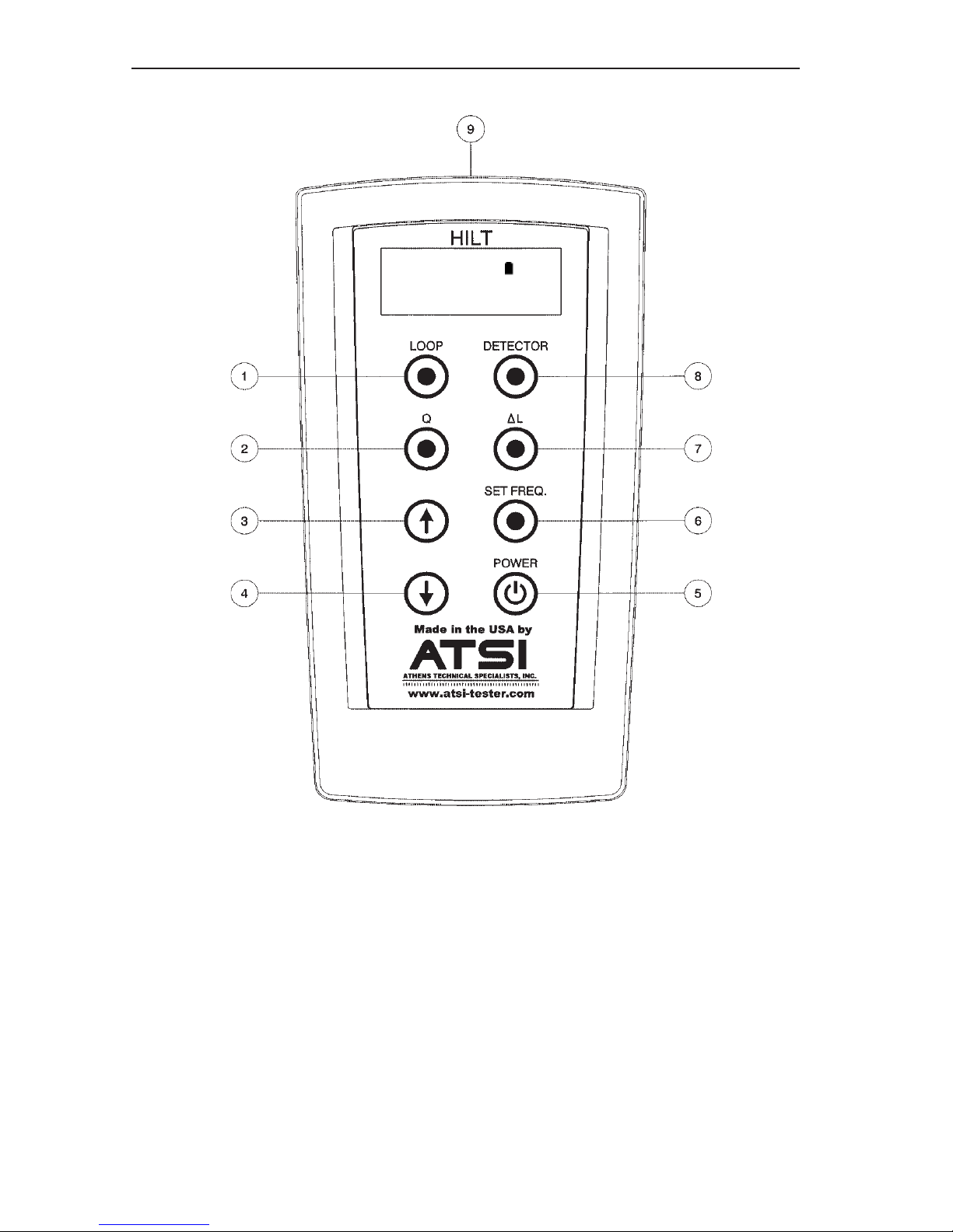
Overview of HILT 9000 Controls
1. LOOP: Measures RDC, L, and
Q. If Q>15, use Q push-
button to obtain actual value.
2. Q: Measures high Q values
(when Q is >15).
3. Used in SET FREQ mode to
increase frequency by 1KHz.
4. Used in SET FREQ mode to
decrease frequency by 1KHz.
5. POWER: Turns unit On/Off.
6. SET FREQ: Selects operating
frequency to measure L & Q.
7.
∆∆
∆∆
∆L: Measures change of
inductance.
8. DETECTOR: Measures
operating parameters of the
loop system: V
P-P
, Oscillating
frequency, and mode.
9. Input: Color coded input
connectors.
Ready: 100%
Select Function
Figure 1
Page 6
5
HILT 9000 - Inductive Loop Tester
Function Controls
Power
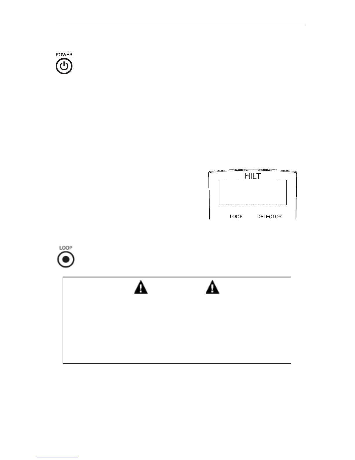
Press the POWER push-button to turn the tester on and off. The
tester performs an initial self-test to verify that the internal
circuit is working. After the self-test is complete, the tester shows
the current battery level and the message: Ready: Select
Function. If the battery is low, a message Replace Battery will
be displayed.
Press and hold the POWER push-button during power-up to
display the serial number of the unit and the version of the
firmware as show in Figure 2. Release
the push-button to return to normal
operation.
The unit can be turned off at any time
by pressing the POWER button. The
tester shuts off automatically after 30
seconds of non-use.
Loop
ATTENTION
• Disconnect the detector from the loop before running
this test.
• DO NOT switch to a different test while the measurements are being generated for the current test. Only
after the results of the current test are displayed can
a different test be performed.
Connect the test leads to the loop. Press the LOOP push-button
to begin the test. After the measurement is complete, the tester
displays the results as shown in Figure 3 on the next page. Note
that the frequency at which L and Q were measured is also
displayed.
HILT-9000 #1234
Self-test v.1.0
Figure 2
Page 7
6
www.atsi-tester.com
The LOOP test can measure a maxi-
mum Q of 15. If Q is greater than 15
the tester displays Q>15. To measure
the actual value, press the Q button on
the keypad to run a separate Q test.
The default frequency at which the
LOOP and Q tests run is 50 KHz. It can
be changed to any value within the
range from 20 KHz to 80 KHz with 1
KHz increment.
Quality (Q)
ATTENTION
• Disconnect the detector from the loop before running
this test.
• DO NOT switch to a different test while the measurements are being generated for the current test. Only
after the results of the current test are displayed can
a different test be performed.
Connect the test leads to the loop. This test requires several
seconds to run during which the tester will measure Q at
some arbitrary frequency and calculate Q for a user-selected
frequency. If a user-selected frequency is not entered prior to
pressing Q, the default 50KHz setting
will be used. Refer to the Set
Frequency section on page 7 for
full instructions to enter a different
frequency.
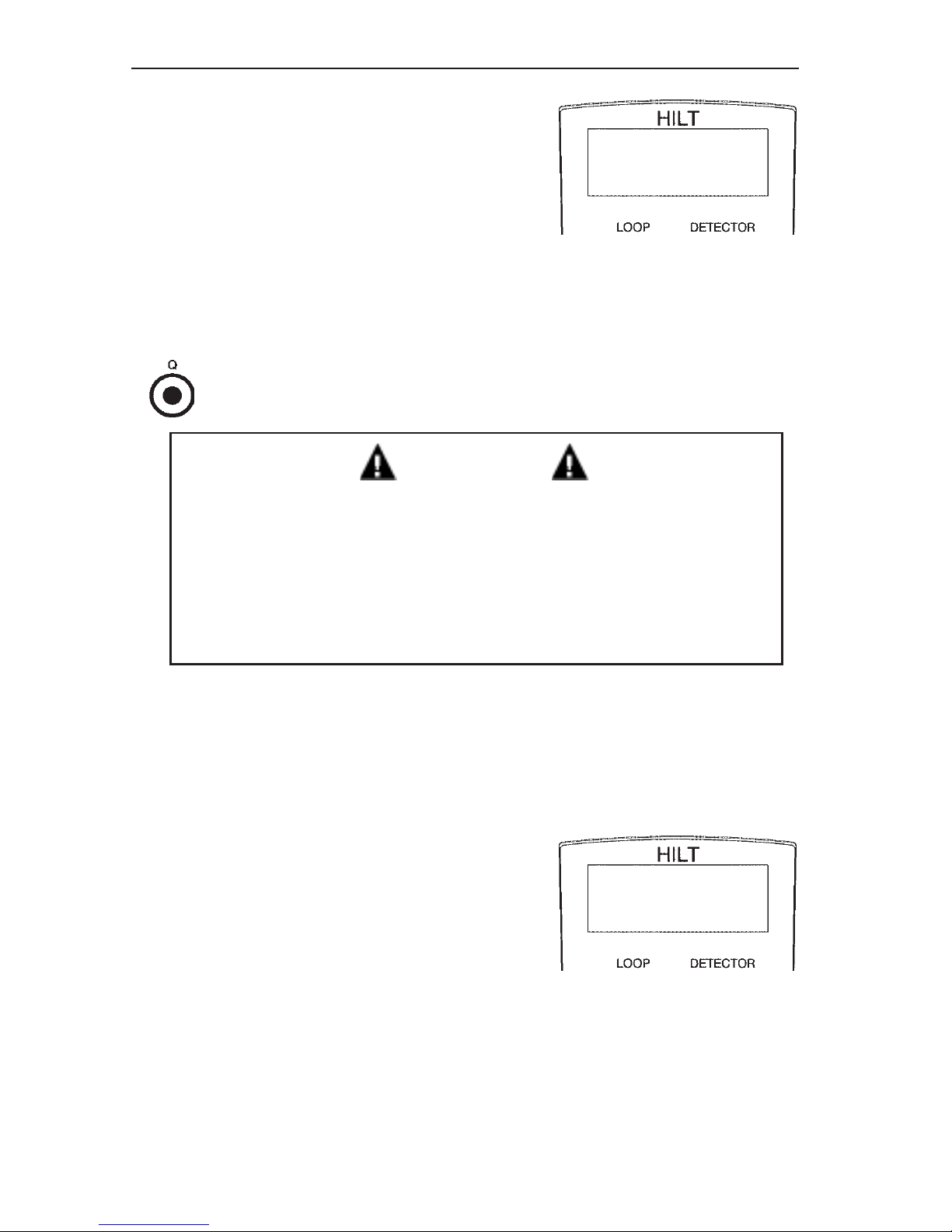
Both Q results will be presented on the
display as shown in Figure 4. The
calculated value is shown on the
second line and indicated with an *.
R=12.3Ω Q=12.1
L=89.2µH 50KHz
Figure 3
Q=12.1 @40.5KHz
*
Q=14.9 @50.0KHz
Figure 4
Page 8
7
HILT 9000 - Inductive Loop Tester
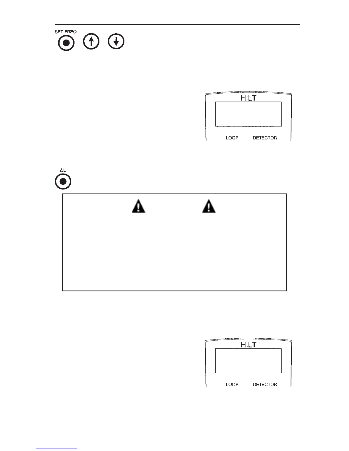
, , Set Frequency
When the tester is powered, the test frequency is automatically
set to 50 KHz. The frequency can be changed to any value
between 20 KHz and 80 KHz with 1 KHz resolution. To set a
different frequency press the SET
FREQ push-button to view the frequency adjustment display as show in
Figure 5. Use the ! or " push-button to
increase or decrease the frequency by
1KHz. Pressing and holding ! or "
button will automatically increase/
decrease the value.
Change of Inductance
ATTENTION
• Disconnect the detector from the loop before running
this test.
• Prior to measuring the operating parameters of the loop
system, press the DETECTOR push-button and verify
the tester displays the “No Signal” message. Once this
message is received the detector can be reconnected to
the loop.
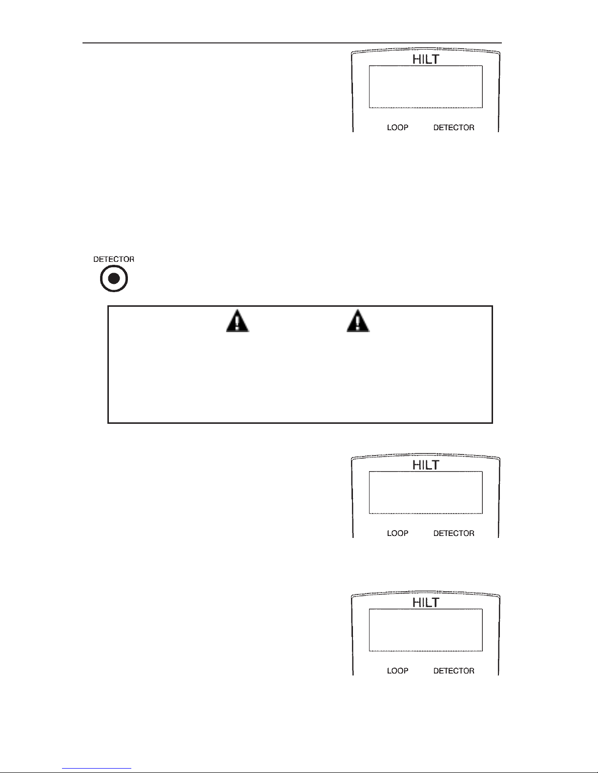
In this mode, the tester simulates a detector by measuring a
relative change of the inductance and displaying the results.
Connect the test leads to the loop and
press
∆∆
∆∆
∆L button on the keypad. The
display will appear as shown in Figure
6. The top line indicates the current
change of the inductance and the
bottom line indicates the maximum
recorded change of inductance. To
reset the maximum value press the
∆∆
∆∆
∆L
button.
Test @ frequency
F=50 KHz
Figure 5
dL/L= 0.127%
max= 3.378%
Figure 6
Page 9
8
www.atsi-tester.com
If there is bad connection, the tester
displays a message as shown in Figure
7. Make sure that the test leads are
properly connected. If the leads are
connected to the loop and the message
is still present, it means that Q of the
loop is too low to generate the oscillation or the inductance is out of range.
This can be verified by performing the
LOOP test.
In this mode, the the tester will shut off automatically after 45
seconds if no buttons are pressed.
Detector
ATTENTION
• Verify the Loop is connected to detection system before
running this test.
• Disconnect the detector from the loop before running a
LOOP, Q, or
∆∆
∆∆
∆L test.
The purpose of this test is to measure
the operating parameters of the
working loop while it is connected to
the detector.
Connect the test leads to the loop and
press the DETECTOR push-button.
During this test the measurements are
constantly updated displaying the type
of the operating mode, peak-to-peak
voltage, and the operating frequency as
show in Figure 8. If the signal is not
present or signal is weak, the tester
displays “No Signal” message as show
in Figure 9.
In this mode, the the tester will shut
off automatically after 45 seconds if no
buttons are pressed.
dL/L:
No loop found
Figure 7
Scan. mode:
7.4V @F=34.1KHz
Figure 8
No signal
-.-V @F=--.-KHz
Figure 9
Page 10
9
HILT 9000 - Inductive Loop Tester
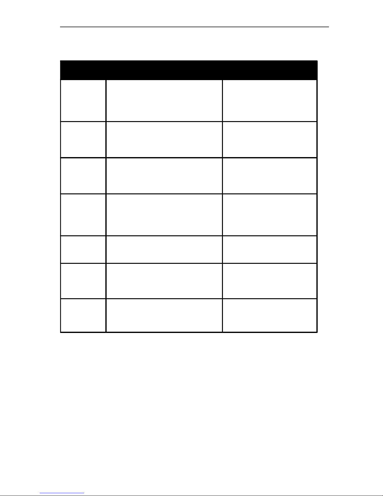
Function Controls Summary
BUTTON DESCRIPTION COMMENTS
LOOP Used to measure L, Q, and R
DC
of the loop. Q is measured up
to 15. If Q>15, use Q button to
obtain the actual value of Q
The loop must be
disconnected from the
system to run this test
Q Used to measure high Q
values (when Q is >15)
The loop must be
disconnected from the
system to run this test
∆L
Used to measure change of
inductance
The loop must be
disconnected from the
system to run this test
DETECTOR Used to measure operating
parameters of the loop
system: V
P-P
, Oscillating
Frequency, and Mode
The loop must be
connected from the
system to run this test
SET FREQ. Used to select operating
frequency to measure L and Q
! and "
Used in SET FREQ mode to
increase and decrease
frequency in 1KHz steps.
POWER Used to turn the unit on and
off.
The tester can be
turned off at any time
during or after a test
Page 11

10
www.atsi-tester.com
Overview of Traffic Loop Detection Systems
The inductive loop represents the most commonly used method
to detect vehicles. The inductive loop is simply a coil of wires
embedded into the pavement and can be characterized by several
parameters, L (inductance), Q (quality factor), R (active resis-
tance, measured using AC signal), and RDC (DC resistance).
These parameters are affected by the type of pavement, number
of turns in the loop, type of wire, length and type of the lead-in
cable, shape and dimension of the loop, and presence of any
objects near the loop.
A detector is connected to the loop and is used to measure the
AC characteristics of the loop and change of those. A part of the
circuitry in the detector and the loop creates an oscillating
circuit. The oscillating frequency of this circuit depends on the
parameters of the loop and the parameters of the detector. When
a vehicle or other metallic mass is located above the loop almost
all of the characteristics (except DC resistance RDC) are altered.
This change causes the oscillating frequency to drift which in
turn is detected by the detector.
Unfortunately, the deterioration of the loop begins virtually from
the moment of installation. There appear to be two basic mechanisms for loop degradation, mechanical and chemical. Under
daily and seasonal temperature variations, the pavement is
constantly flexing. To this may be added the pounding of heavy
vehicles, particularly at the approaches to signalized intersections where loops are often located. These mechanical factors
cause flexure of the wires comprising the loop, especially at the
juncture between pavement and berm, leading initially to fine
cracks in the insulation, and perhaps ultimately to actual
breakage of the wires. After insulation failure occurs (fine cracks
or breakage), there is a path for water intrusion. While water
itself is a poor conductor, its conductivity is greatly increased by
the highly ionic de-icing salts which saturate the berm and all
cracks and fissures of the pavement. Aside from the ground
leakage which results, these highly active solutions can actually
erode the copper conductors by displacement, aided by electrolysis of even the small potentials of the wire to ground. Lead-in
wires are also vulnerable, especially on long pulls through
conduit, because of the high probability of minor insulation
failures due to chafing and stretching during installation.
Page 12

11
HILT 9000 - Inductive Loop Tester
To guarantee a reliable oscillation in the loop system the quality
factor (Q) of the loop with the lead-in wires should be above some
value, determined by the amplifiers inside the detector. Deterio-
ration of the loop and lead-in wires reduces Q and eventually
prevents the system from oscillating even with a known good
detector.
Battery replacement
NEVER OPEN THE BATTERY COMPARTMENT
WHILE THE HILT-9000 POWER IS ON.
The battery indicator (in percentage format) on the LCD indicates
when the batteries in the HILT-9000 require replacement. There
are two 9V alkaline batteries in the HILT. Recommended replacement type is Alkaline (IEC 6LF22, 6LR61 or NEDA 1604A).
To replace the batteries, you will need to open the battery cover
on the backside of the tester. Lay the tester face-down on a flat
table, making sure that there is nothing underneath the tester
that can accidentally turn the tester on. Remove the two Phillips
head screws that secure the battery cover. The battery cover can
then be removed and access to the batteries obtained. Installation is the reverse of this procedure.
All other types of services needed for the HILT -9000 should only
be performed by an ATSI factory technician. Any attempt at
servicing the tester yourself or by someone other than a ATSI
technician will void the factory warranty. See the Warranty
statement at the end of this manual for full details.
Page 13

12
www.atsi-tester.com
Commonly Asked Questions
Q. Why do I have to disconnect the detector from the loop before
running a Loop, Q, or
∆∆
∆∆
∆
L test?
A. During Loop, Q, and ∆L test, the tester is applying its own
signal to the loop. The tester verifies there is no signal on the
loop before running these tests. However, with a scanning
detector connected to the loop, there are time intervals during
which the loop does not have a signal applied. If the verification
occurs during that time interval, the HILT will not “see” that
there is another source of voltage connected to the loop and will
begin the actual test. Presence of another voltage on the loop will
result with incorrect measurements or potentially damage the
tester.
Q. When I run a Q test, why are there two results shown?
A. The quality factor Q depends not only on the parameters of
the loop but also the frequency of the measuring signal. During
a Q test, the tester measures Q at a natural resonant frequency,
which depends not only on the parameters of the loop but also
those of the tester and it will not be the same as the user-
selected frequency. The Q measurement for the natural resonant
frequency is displayed on the first line. The Q for the user-
selected frequency is calculated and is displayed on the second
line.
Q. Is an adapter available to plug into the detector rack that will
allow testing from the detector’s connection points?
A. Yes. Call your distributor or the factory for pricing and
availability.
Page 14

13
HILT 9000 - Inductive Loop Tester
Repair and Calibration
To ensure that your instrument meets factory specifications, we
recommend that it be returned to our factory at one-year
intervals for calibration service. In addition to calibration of the
test parameters, this service includes replacement of batteries
and firmware updates. Please contact the factory for price and
scheduling information on this service.
Request a Return Merchandise Form by phone or by fax from
our Service Department (or complete the form on our website at
www.atsi-tester.com), then return the tester along with the
completed RM Form. Return the tester, postage or shipment
pre-paid to:
ATSI
8157 US Route 50 • Athens, OH 45701
(740) 592-2874
(740) 594-2875 - Fax
[email protected]
Caution: To protect yourself against in-transit loss, we recommend you insure your returned materials.
The HILT-9000 is sold with a one-year limited warranty to the
original purchaser, as defined by the limited warranty on the
inside back cover of this manual. No other warranties, expressed
or implied, apply to the HILT -9000 or associated components.
After the first year, ATSI will continue to provide repairs to the
tester on a parts-plus-labor basis. A phone call describing the
problem may allow ATSI to make a nonbinding estimate of repair
costs, but the surest approach is to send back the tester for a
comprehensive evaluation and a binding repair estimate.
Page 15

14
www.atsi-tester.com
Technical and Sales Assistance
If you are experiencing any technical problems, or require any
assistance with the proper operation or application of your
tester, please call, fax, or e-mail our technical support staff:
ATSI
8157 US Route 50 • Athens, OH 45701
(740) 592-2984
(740) 594-2875 - Fax
[email protected]
NOTES
Page 16

15
HILT 9000 - Inductive Loop Tester
-- This page left blank --
Page 17

16
www.atsi-tester.com
Limited Warranty
The HILT 9000 (“Product”), distributed by Athens Technical Specialists, Inc.
(ATSI), is warranted to the original purchaser (“Purchaser”) to be free of
defects in materials and workmanship for a period of one year from the
purchase date stated on the invoice. Within this period, in the event of a
defect, malfunction, or other failure of the product while in the custody of
the purchaser, ATSI will remedy the defect or cause of failure without
charge to the Purchaser. Purchaser’s sole remedy is restoration of product
operation. ATSI accepts no liability for incidental or related expenses. Under
no circumstances will ATSI’s liability exceed the purchase price for items
claimed to be defective.
This Limited Warranty does not extend to any Product that has been
damaged or rendered defective (a) as a result of accident, misuse, or abuse:
(b) by modification of the product: or (3) as a result of service by anyone
other than ATSI.
EXCEPT AS EXPRESSLY SET FORTH IN THIS WARRANTY, ATSI MAKES NO
OTHER WARRANTIES, EXPRESS OR IMPLIED, INCLUDING ANY IMPLIED
WARRANTIES OF MERCHANTABILITY AND FITNESS FOR A PARTICULAR
PURPOSE. ATSI EXPRESSLY DISCLAIMS ALL WARRANTIES NOT STATED
IN THIS LIMITED WARRANTY.ANY IMPLIED WARRANTIES THAT MAY BE
IMPOSED BY LAW ARE LIMITED TO THE TERMS OF THIS EXPRESS
LIMITED WARRANTY.
Warranty Repair
What you must do to return the tester for Warranty Repair:
Request a Return Merchandise Form by phone or by fax from our Service
Department (or complete the form on our website at www.atsi-tester.com),
then return the tester along with the completed RM Form. Return the
tester, postage or shipment pre-paid to:
ATSI
8157 US Route 50
Athens, OH 45701
(740) 592-2874
(740) 594-2875 - Fax
[email protected]
Caution: To protect yourself against in-transit loss, we recommend you
insure your returned materials.
YOU CAN NOW REGISTER ONLINE AT:
www.atsi-tester.com
 Loading...