

Page 1
INDEX
Copyright © ATSG 2002
AXOD/AXODE (AX4S)
UPDAT E H A N D B O O K
HYDRAULIC SYSTEM CHANGES .................................................................................................................. 4
SPACER PLATE IDENTIFICATION ................................................................................................................. 9
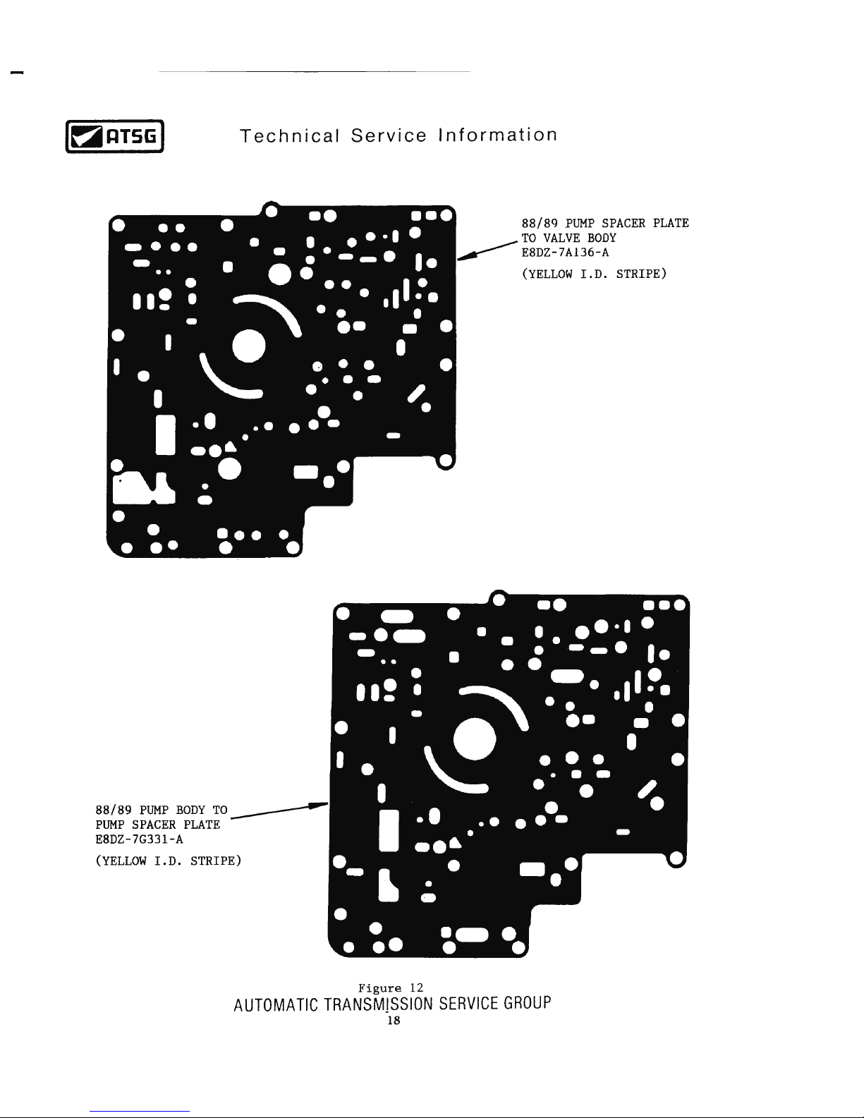
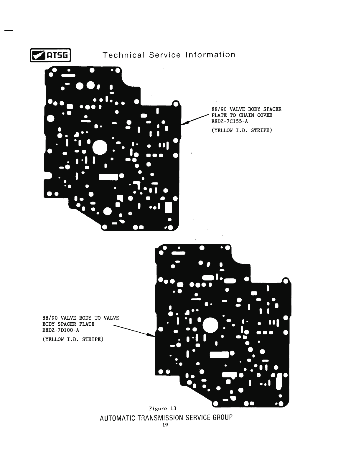
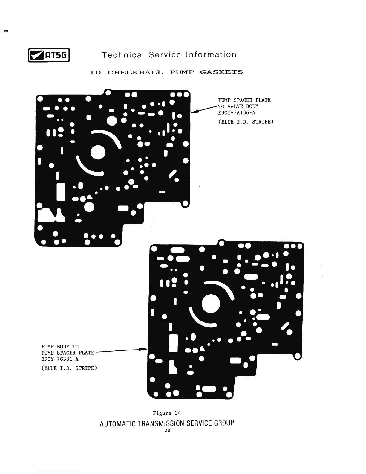
PUMP AND VLAVE BODY GASKET IDENTIFICATION ............................................................................. 14
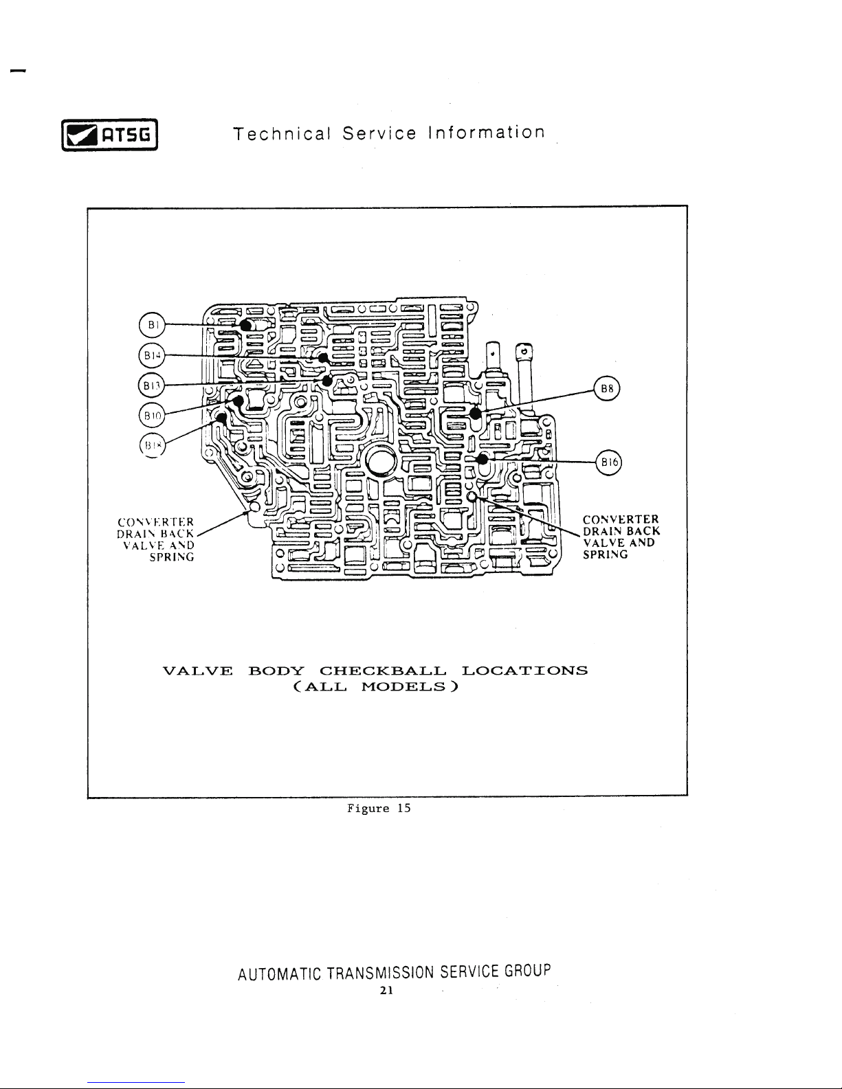
VALVE BODY CHECKBALL LOCATIONS ..................................................................................................... 21
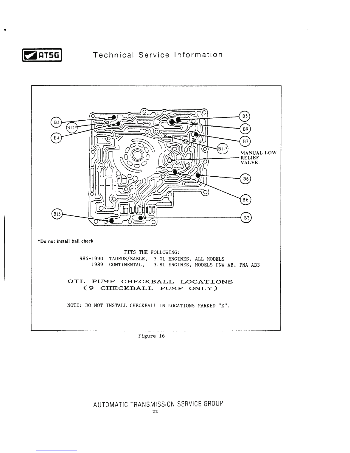
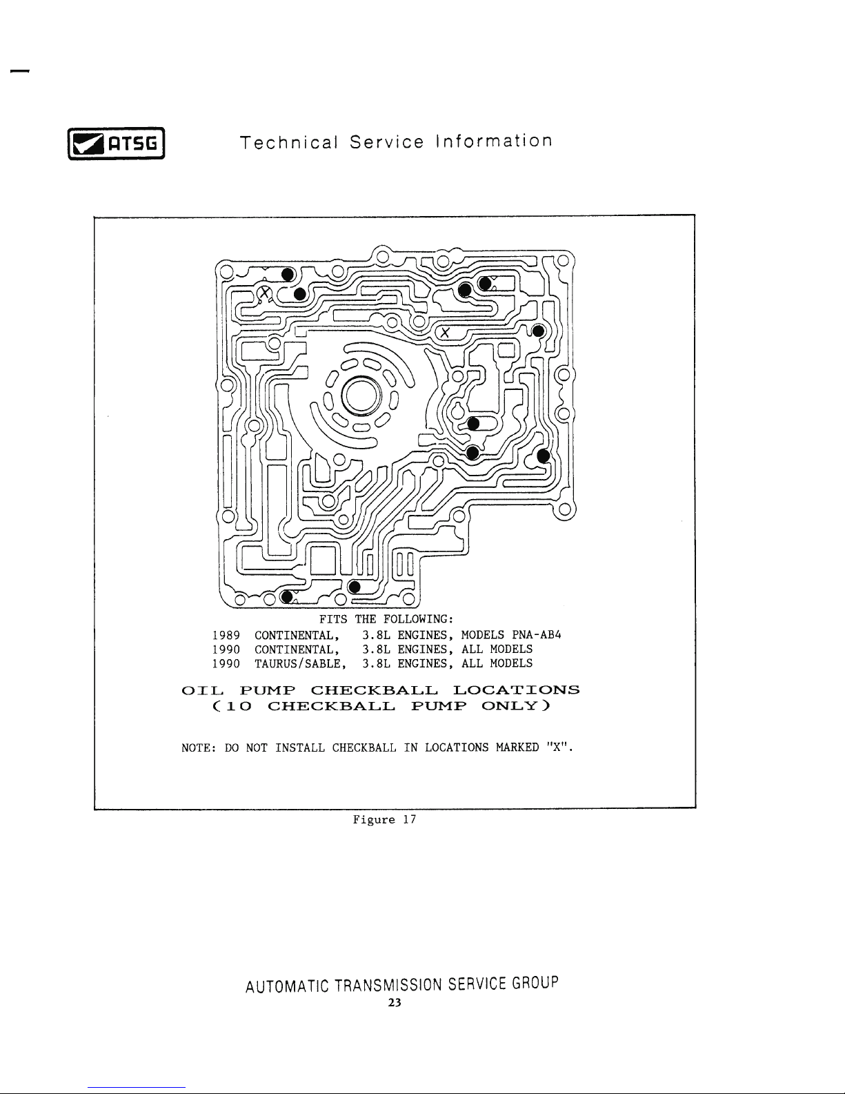
OIL PUMP CHECKBALL LOCATIONS .......................................................................................................... 22
VALVE BODY VALVE LOCATIONS AND IDENTIFICATION ..................................................................... 26
PREMATURE PLANETARY FAILURE ............................................................................................................ 34
INTERMEDIATE CLUTCH PACK CHANGES ............................................................................................... 40
NEW STEEL FORWARD CLUTCH PISTON .................................................................................................. 48
HARSH COASTDOWN SHIFT .......................................................................................................................... 49
SPROCKET RATIO IDENTIFICATION (ALL) ............................................................................................... 51
NEW DESIGN OIL PUMP BEARING WITH INTEGRAL SEAL ................................................................. 56
ACCUMULATOR SPRING IDENTIFICATION (ALL) .................................................................................. 58
LOW SPRAG FREEWHEEL DIRECTION ..................................................................................................... 62
FORWARD CLUTCH WAVE PLATE CHANGE ............................................................................................. 64
FORWARD CLUTCH PACK AND LOW SPRAG OUTER RACE CHANGE ............................................. 68
NEW DESIGN INPUT PLANETARY AND SUN SHELL ............................................................................... 72
NO MOVEMENT OR NO TCC .......................................................................................................................... 75
OIL PUMP CHECKBALL LOCATION CHANGES ........................................................................................ 76
TORQUE CONVERTER AND TURBINE SHAFT SPLINE CHANGES ....................................................... 79
VALVE BODY VALVE LOCATIONS AND IDENTIFICATION ..................................................................... 80
VALVE BODY AND OIL PUMP SPACER PLATE IDENTIFICATION ........................................................ 88
OIL PUMP AND VALVE BODY GASKET IDENTIFICATION ..................................................................... 89
VALVE BODY CHECKBALL LOCATION CHANGES .................................................................................. 92
PREMATURE PLANETARY FAILURE ............................................................................................................ 95
CHAIN COVER AND THRUST WASHER CHANGES ................................................................................... 96
1991-1992 ELECTRICAL DIAGNOSIS ........................................................................................................... 100
NEW DESIGN CHAIN COVER KIT FOR NEW CASE CONNECTOR ..................................................... 103
1993-UP ELECTRICAL DIAGNOSIS .............................................................................................................. 104
NEW DESIGN TCC SOLENOID ...................................................................................................................... 106
VEHICLE SPEED SENSOR CHANGES ......................................................................................................... 108
PRESSURE TAP LOCATIONS ......................................................................................................................... 111
PRESSURE CONTROL PROBLEM DIAGNOSIS ......................................................................................... 112
WINDSTAR AND TAURUS SPACER PLATE IDENTIFICATION .............................................................. 116
LATEST CHAIN COVER AND GASKET CHANGE (NO REVERSE) ........................................................ 119
AXOD AND AXODE
AXODE
AUTOMATIC TRANSMISSION SERVICE GROUP
18639 S.W. 107TH AVENUE
MIAMI, FLORIDA 33157
(305) 670-4161
2
Page 2

INTRODUCTION
DALE ENGLAND
FIELD SERVICE CONSULTANT
ED KRUSE
TECHNICAL CONSULTANT
WAYNE COLONNA
TECHNICAL SUPERVISOR
PETER LUBAN
TECHNICAL CONSULTANT
JIM DIAL
TECHNICAL CONSULTANT
GREGORY LIPNICK
TECHNICAL CONSULTANT
JERRY GOTT
TECHNICAL CONSULTANT
JON GLATSTEIN
TECHNICAL CONSULTANT
DAVID CHALKER
TECHNICAL CONSULTANT
MIKE SOUZA
TECHNICAL CONSULTANT
ROLAND ALVAREZ
TECHNICAL CONSULTANT
GERALD CAMPBELL
TECHNICAL CONSULTANT
No part of any ATSG publication may be reproduced, stored in any retrieval system or transmitted in any form or
by any means, including but not limited to electronic, mechanical, photocopying, recording or otherwise,
without written permission of Automatic Transmission Service Group. This includes all text illustrations,
tables and charts.
The information and part numbers contained in this booklet have
been carefully compiled from industry sources known for their
reliability, but ATSG does not guarantee its accuracy.
Copyright © ATSG 2002
Updated
October, 2002
Since the introduction of the Ford AXOD transaxle in model year 1986, there have been many major
engineering design changes that have affected many of the parts used in the AXOD transaxle. This version of
the AXOD "Update Handbook" begins with the 1986 model year and will explain each change, the parts
affected by the change, and any parts interchange problems created by the change. This booklet is an updated
version of the original.
This updated version of the AXOD "Update Handbook" will also cover the changes that occured in the 1991
model year, when electronic controls were adapted to the AXOD transaxle, making it an AXODE, and now
called an AX4S transaxle. We have included the changes on the AX4S transaxle up through and including
model year 2002.
We wish to thank Ford Motor Company for the information and illustrations that have made this possible.
1
AUTOMATIC TRANSMISSION SERVICE GROUP
18639 S.W. 107TH AVENUE
MIAMI, FLORIDA 33157
(305) 670-4161
Page 3
Page 4
Page 5
Page 6
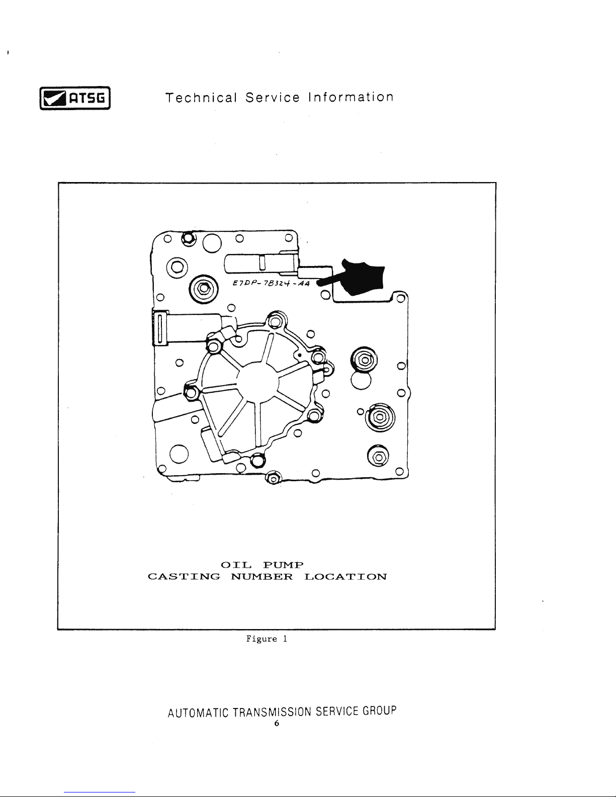
Page 7
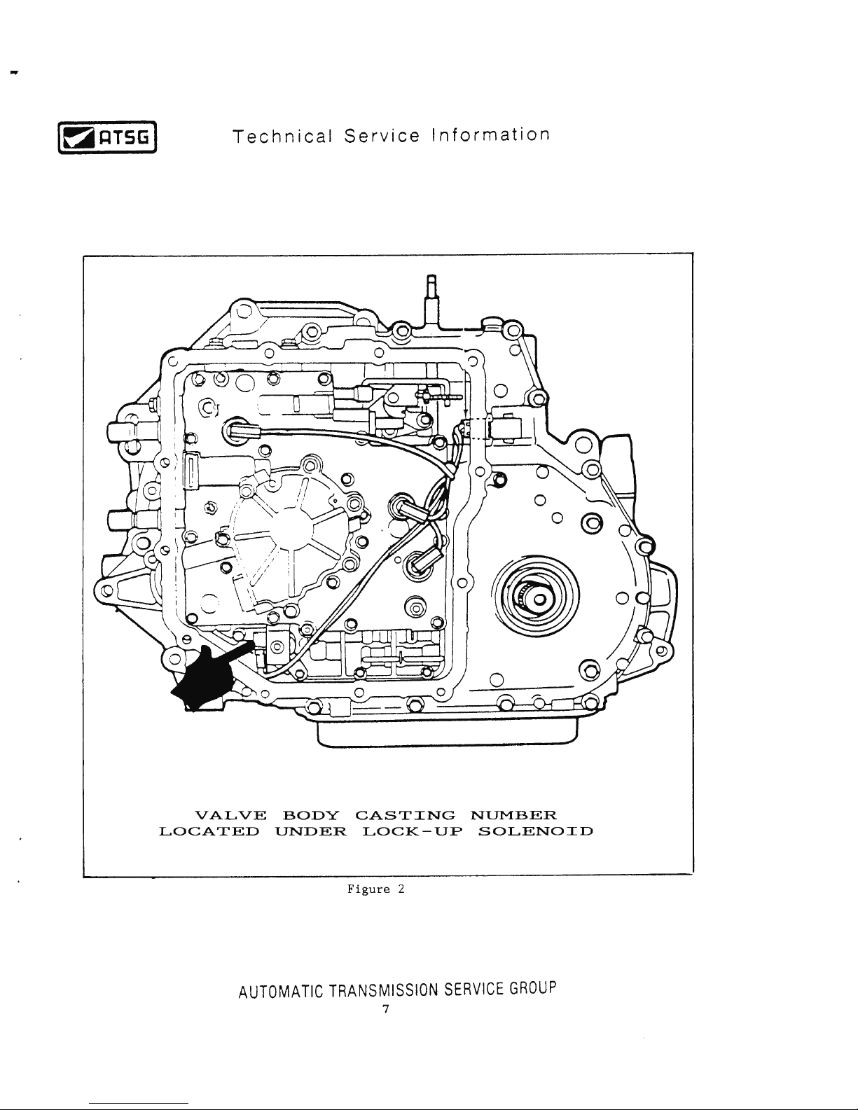
Page 8
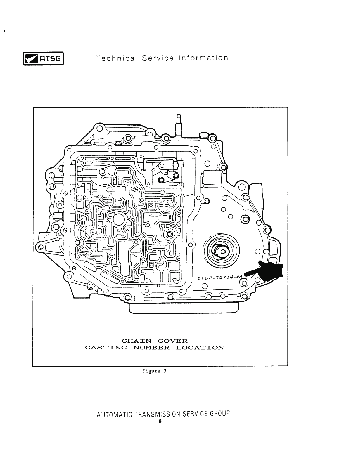
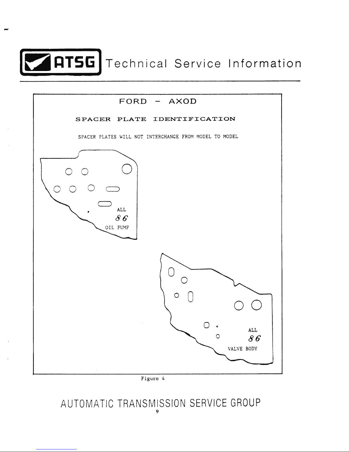
Page 9
Page 10
Page 11
Page 12
Page 13
Page 14
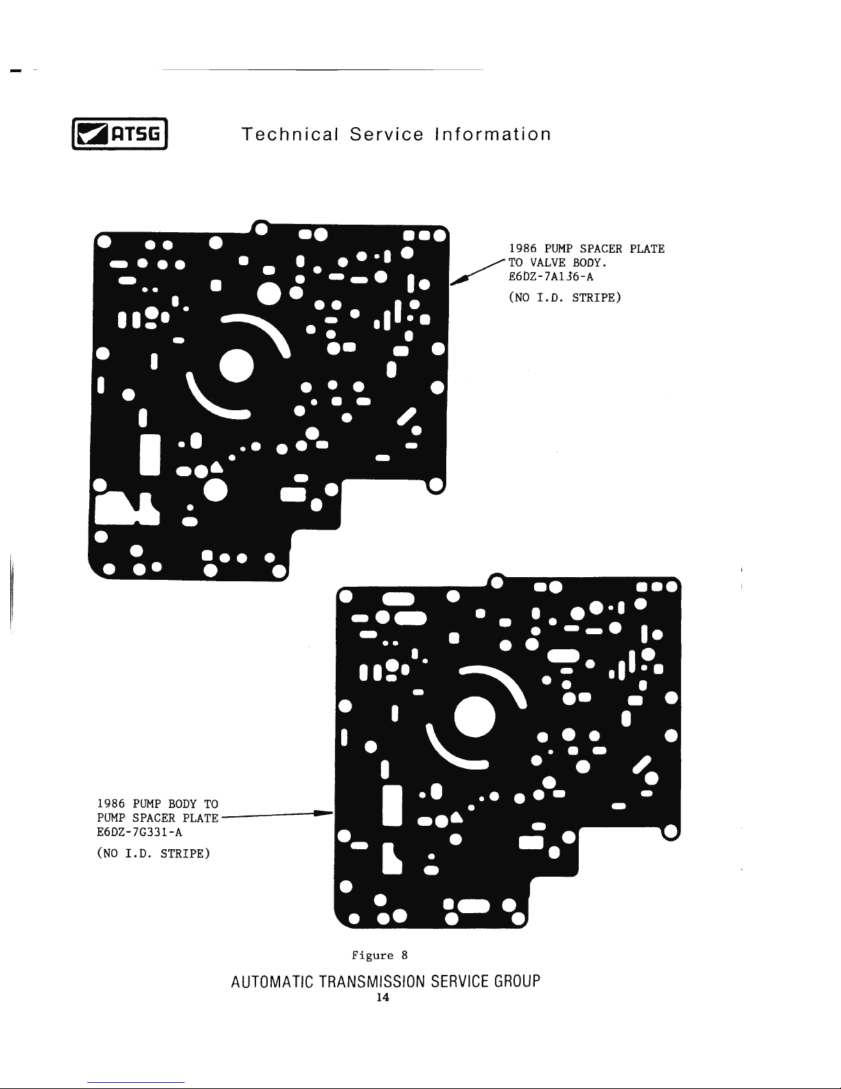
Page 15
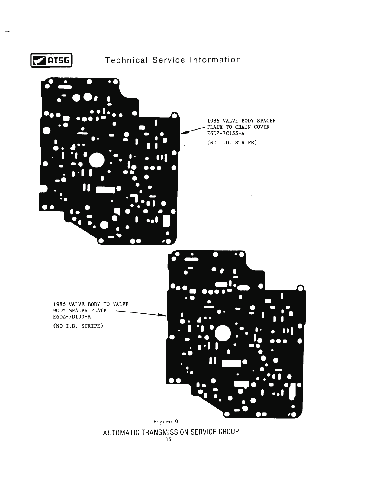
Page 16
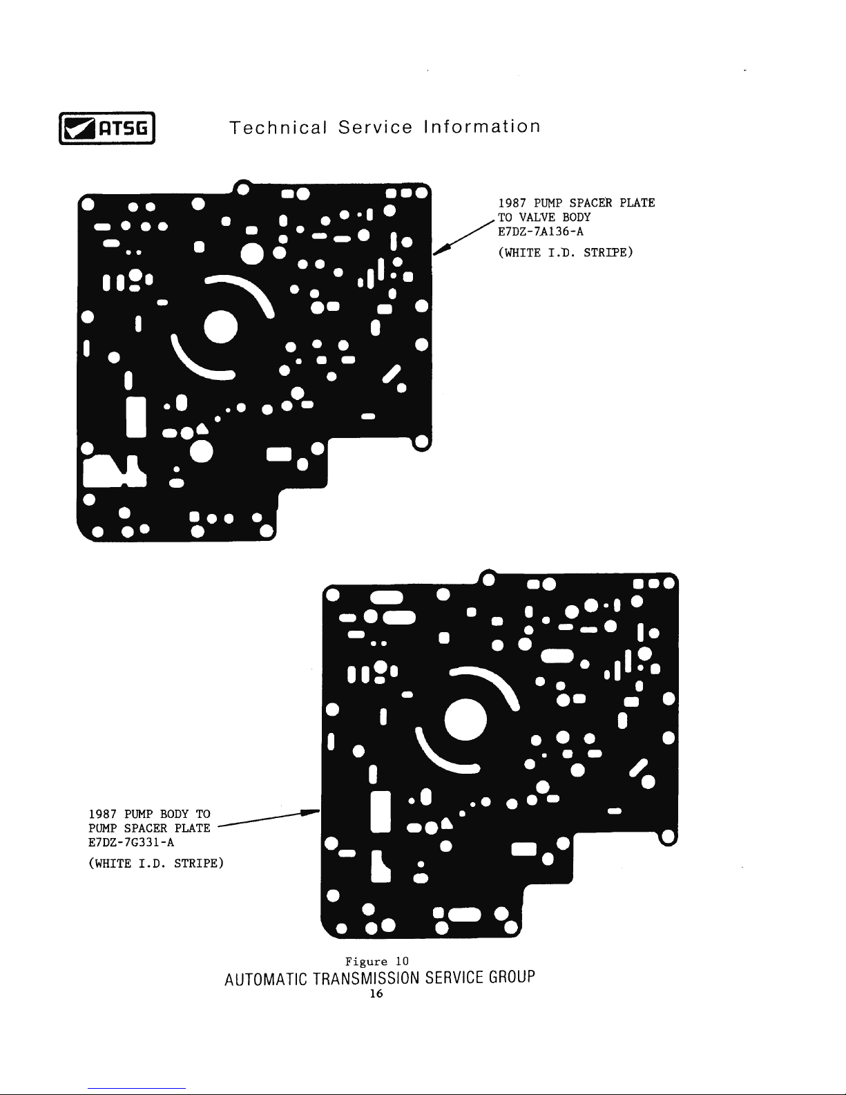
Page 17
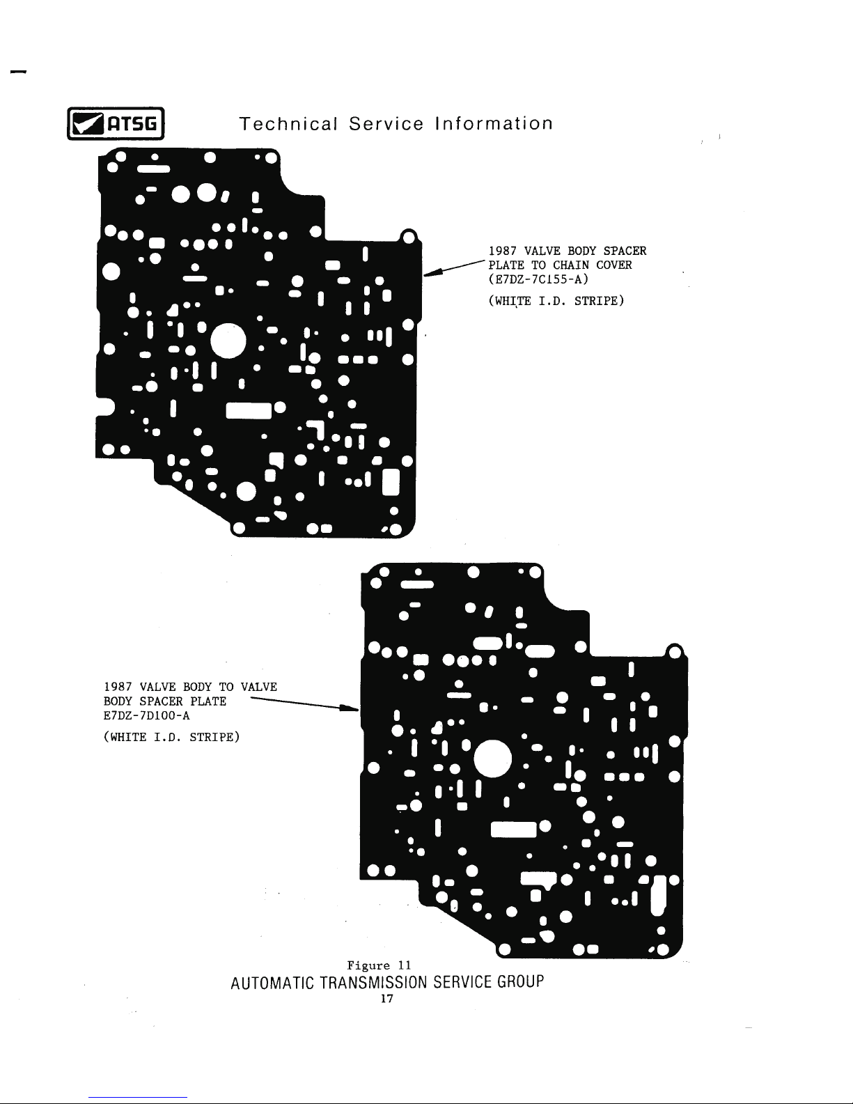
Page 18
Page 19
Page 20
Page 21
Page 22
Page 23
Page 24
Page 25
Page 26
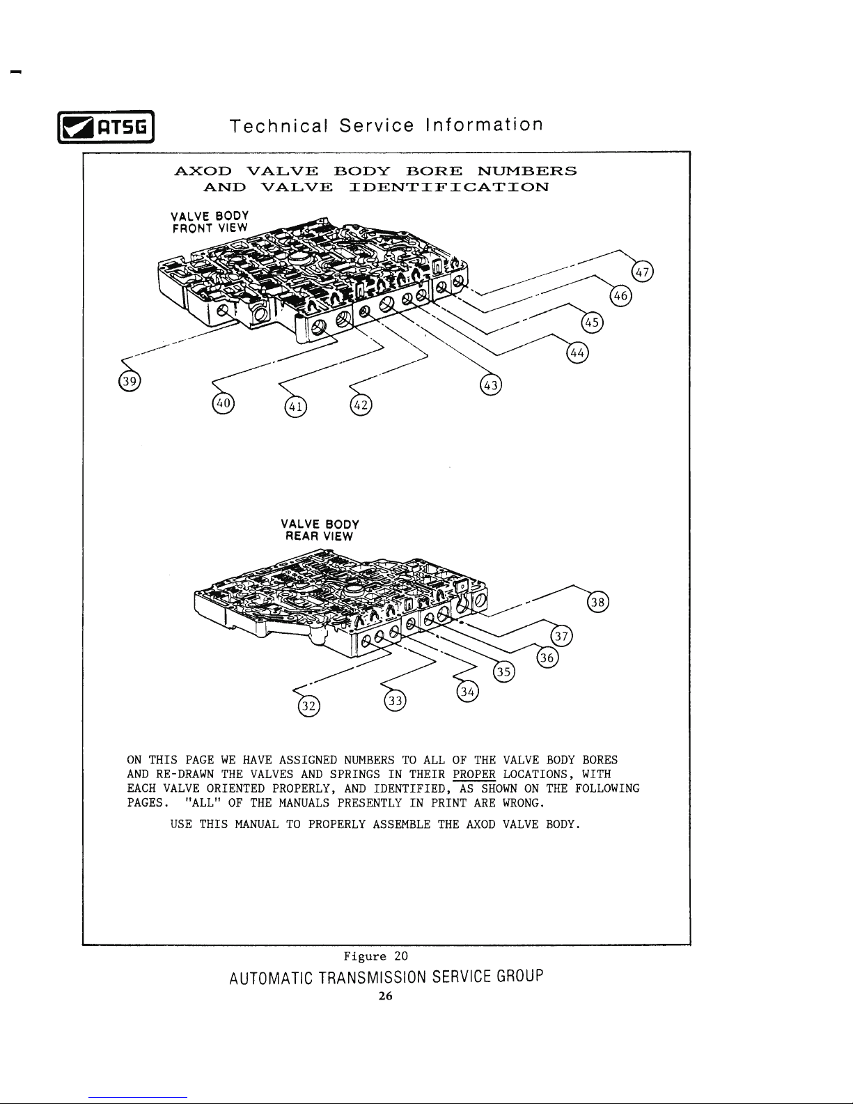
Page 27
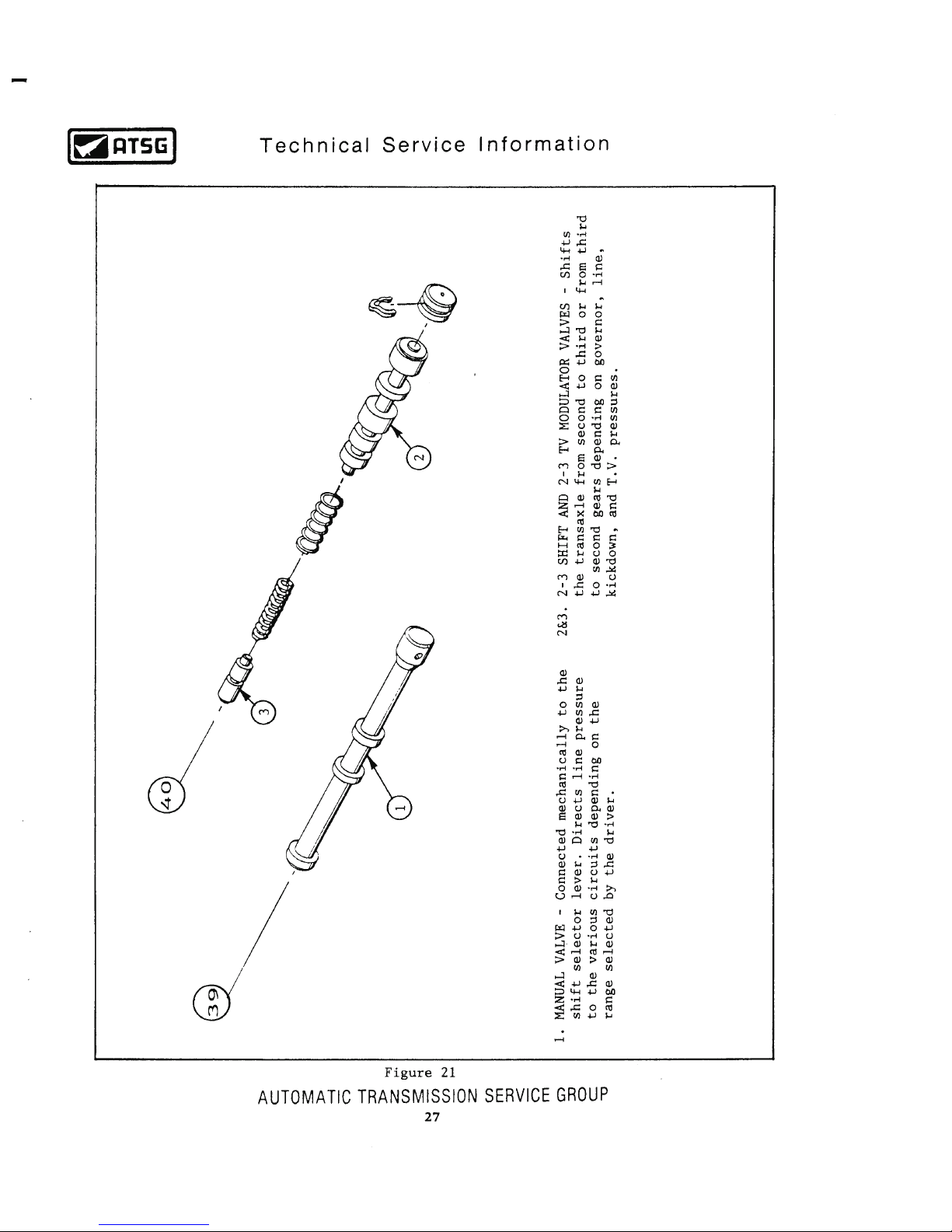
Page 28
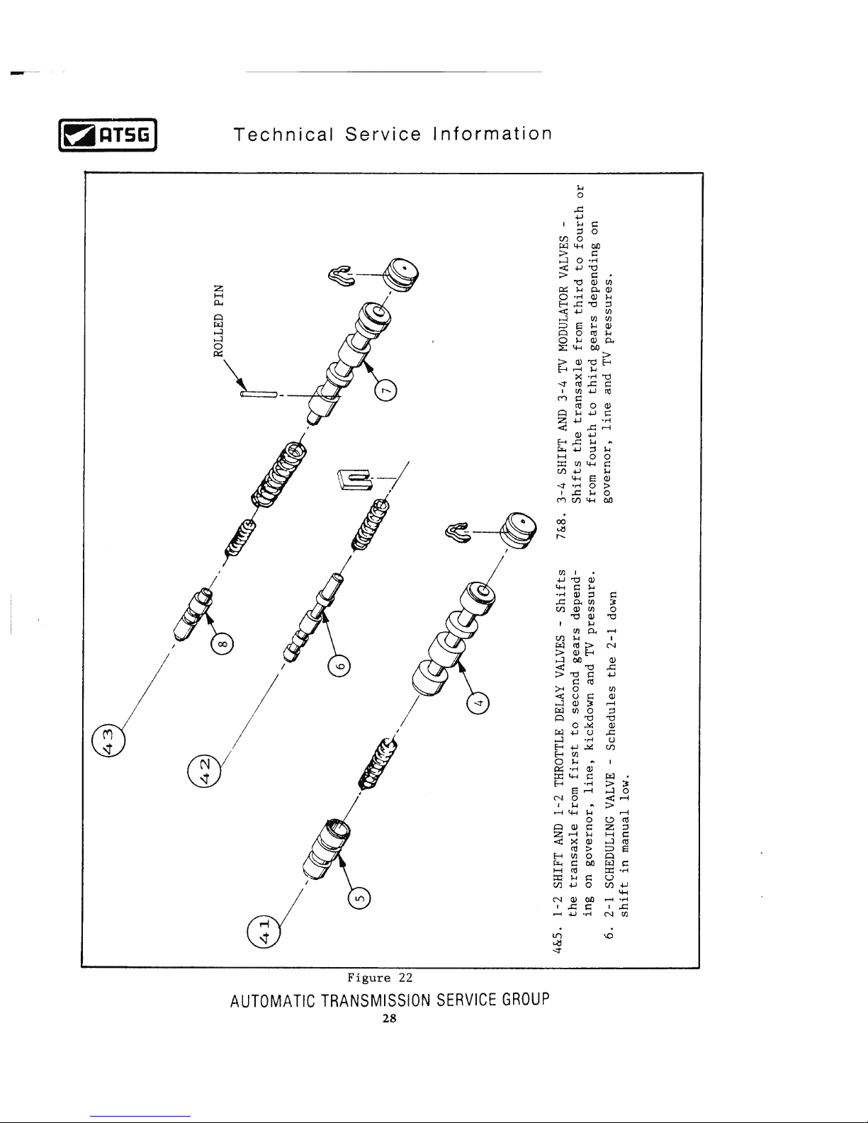
Page 29
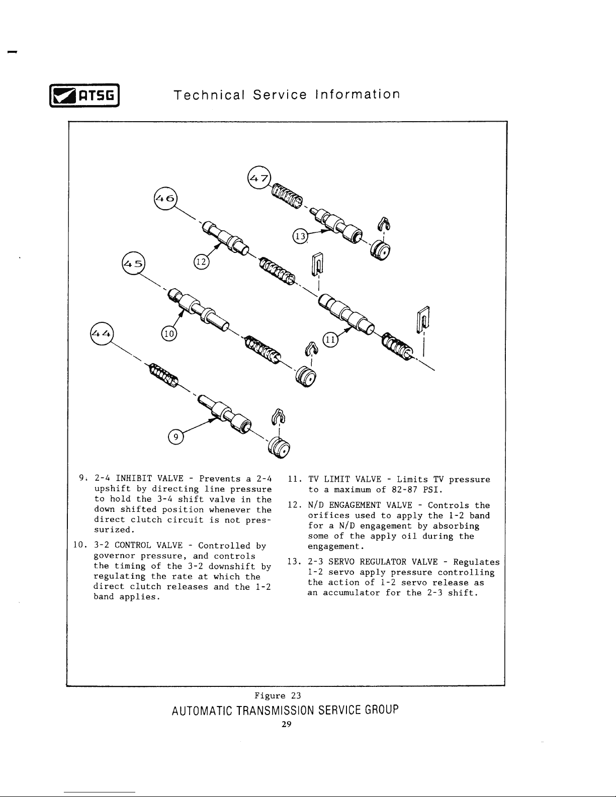
Page 30
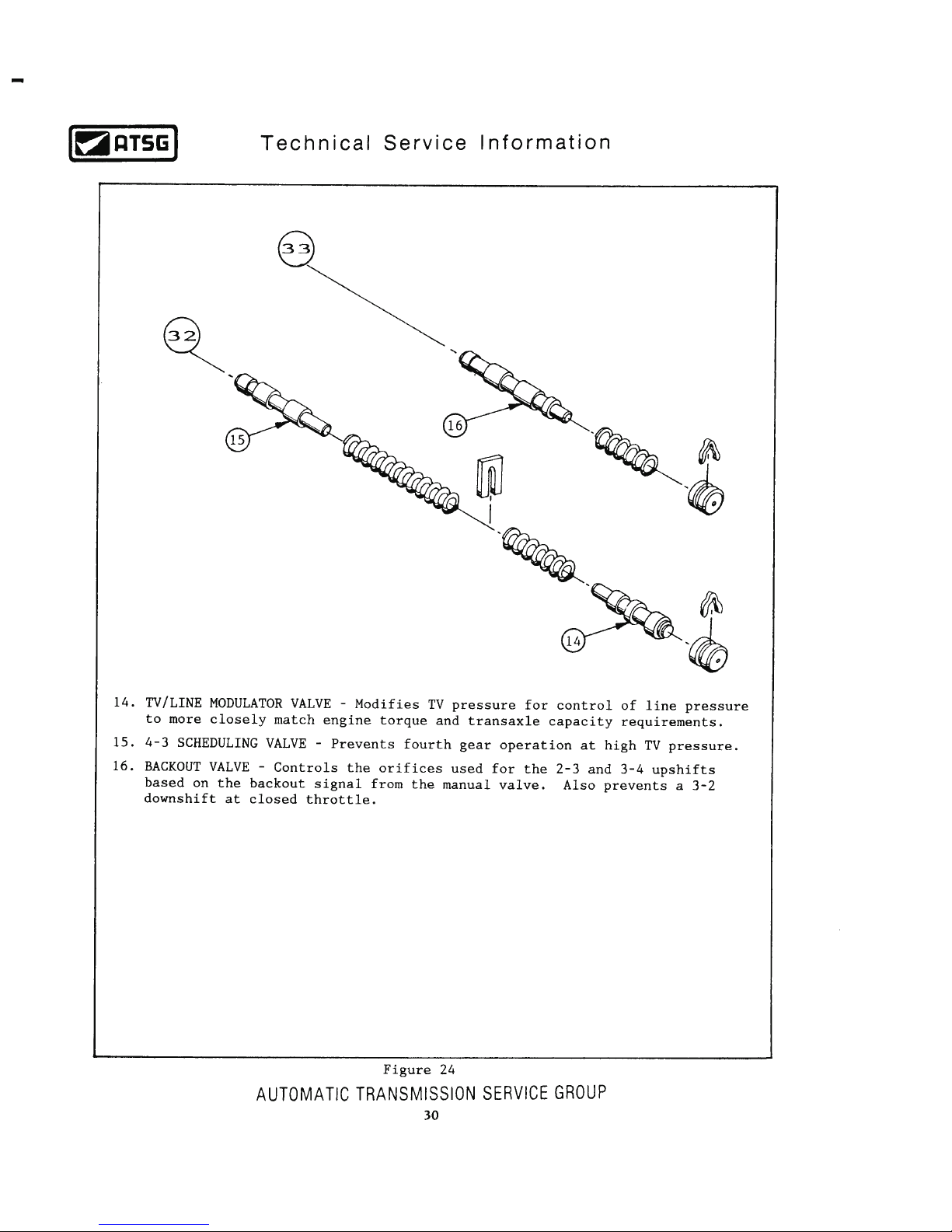
Page 31
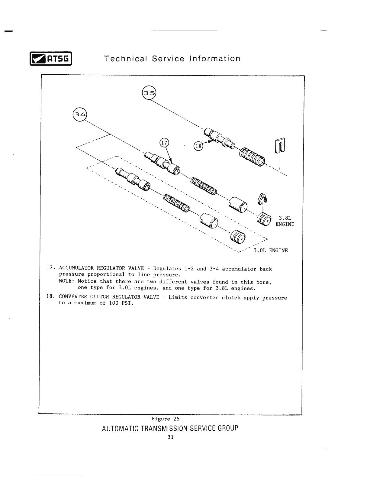
Page 32
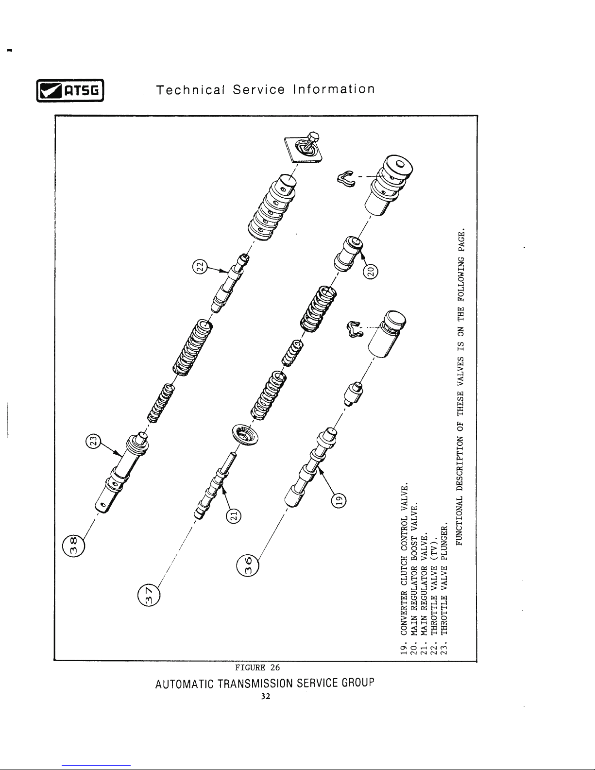
Page 33
Page 34
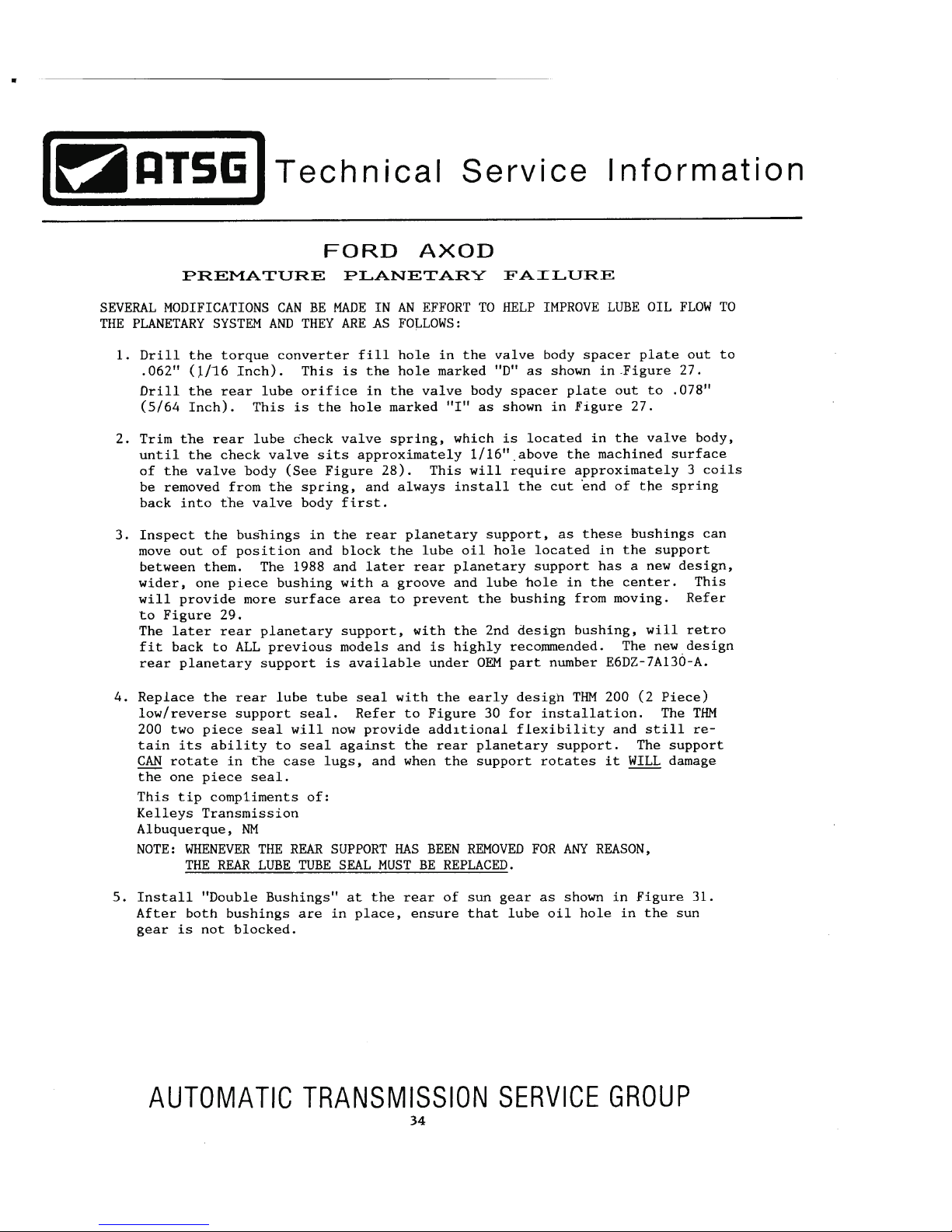
Page 35
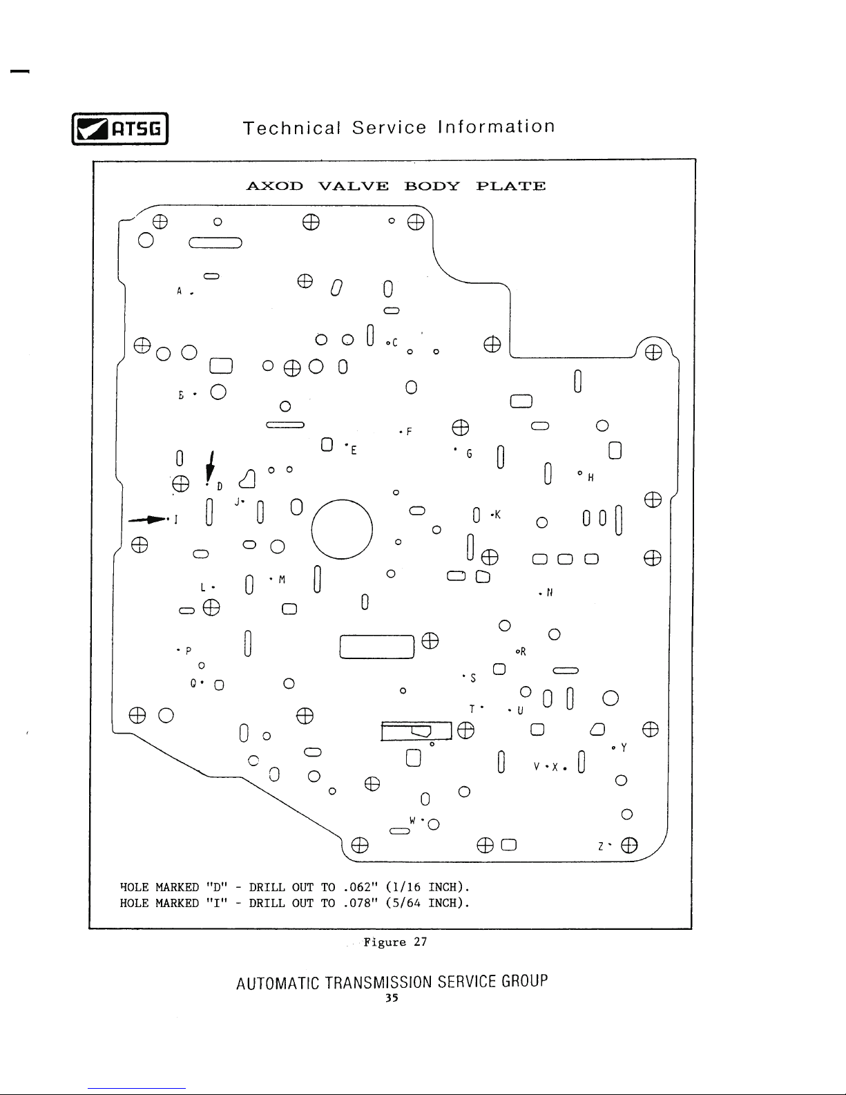
Page 36
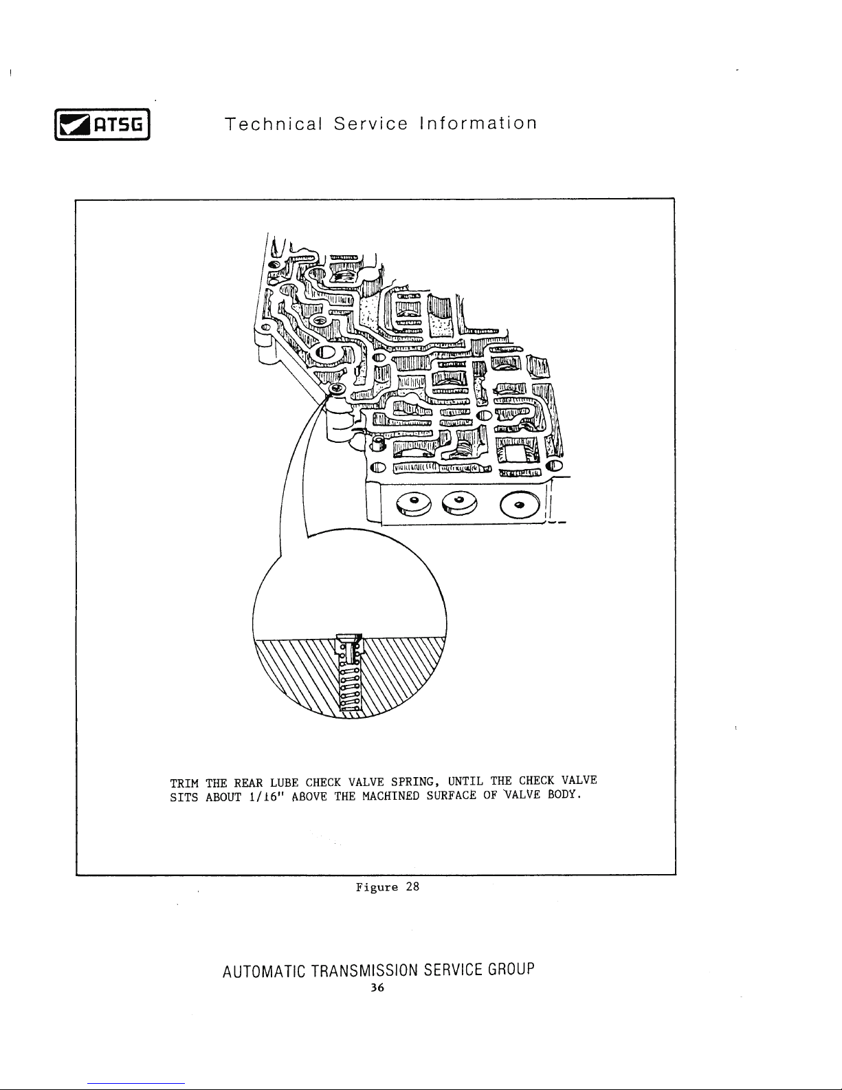
Page 37
Page 38
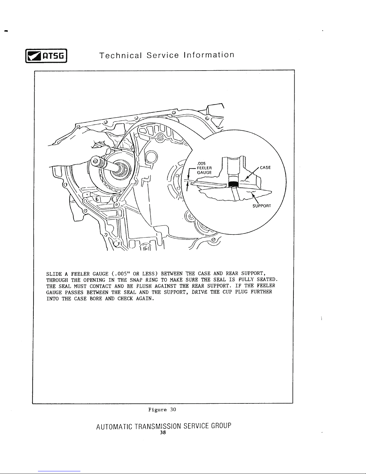
Page 39
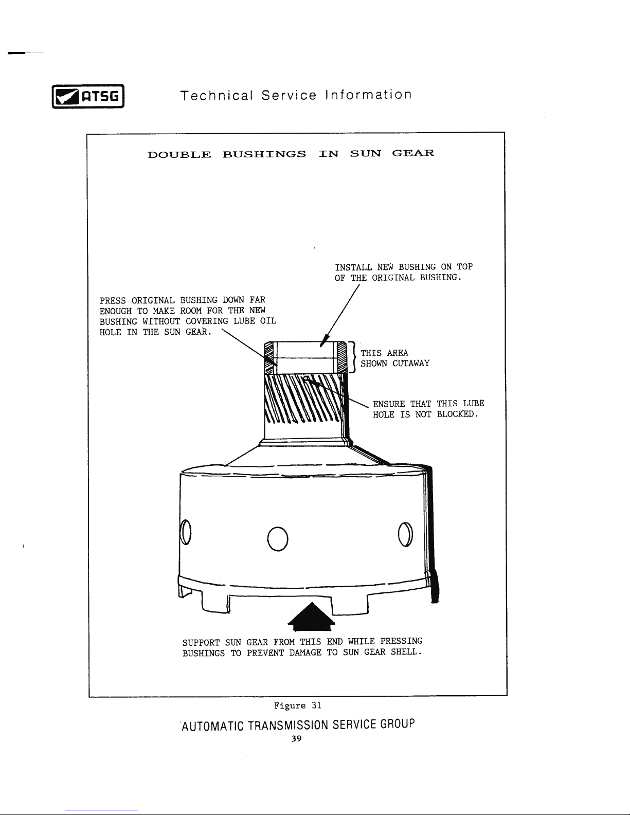
Page 40
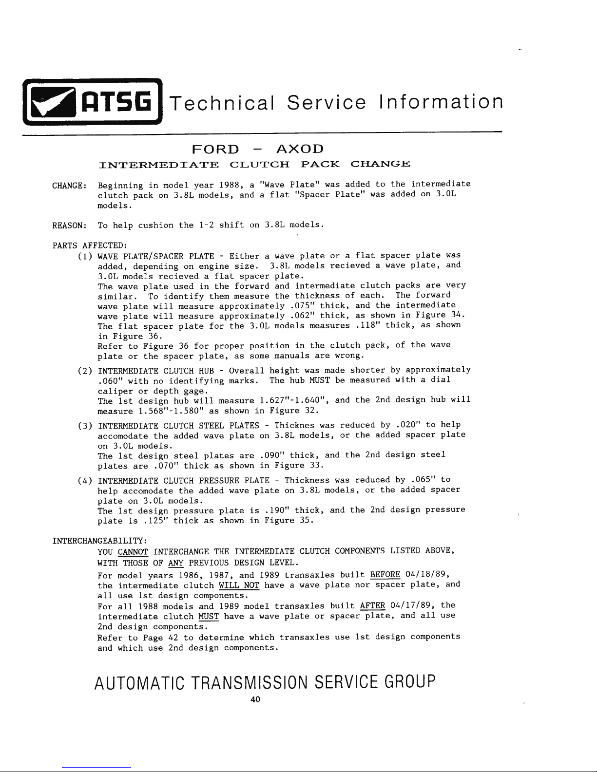
Page 41
Page 42
Page 43
Page 44
Page 45
Page 46
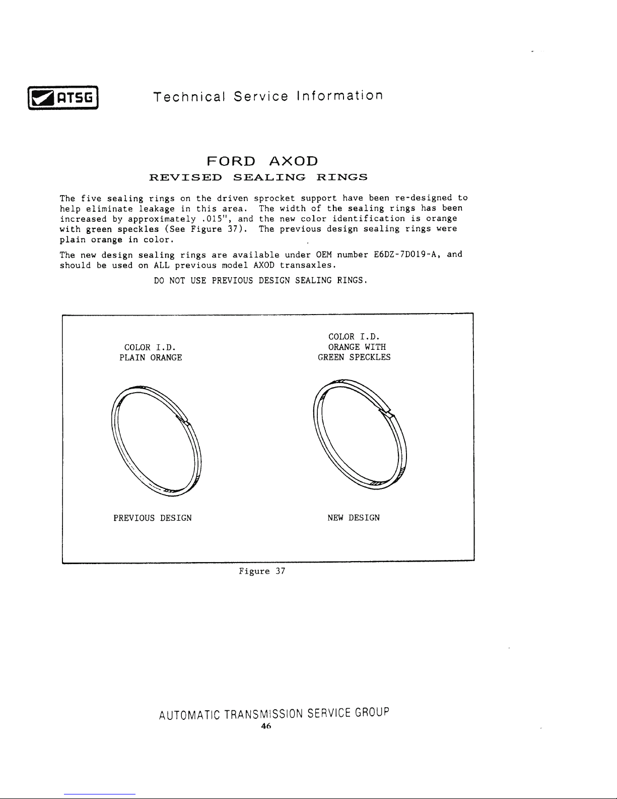
Page 47
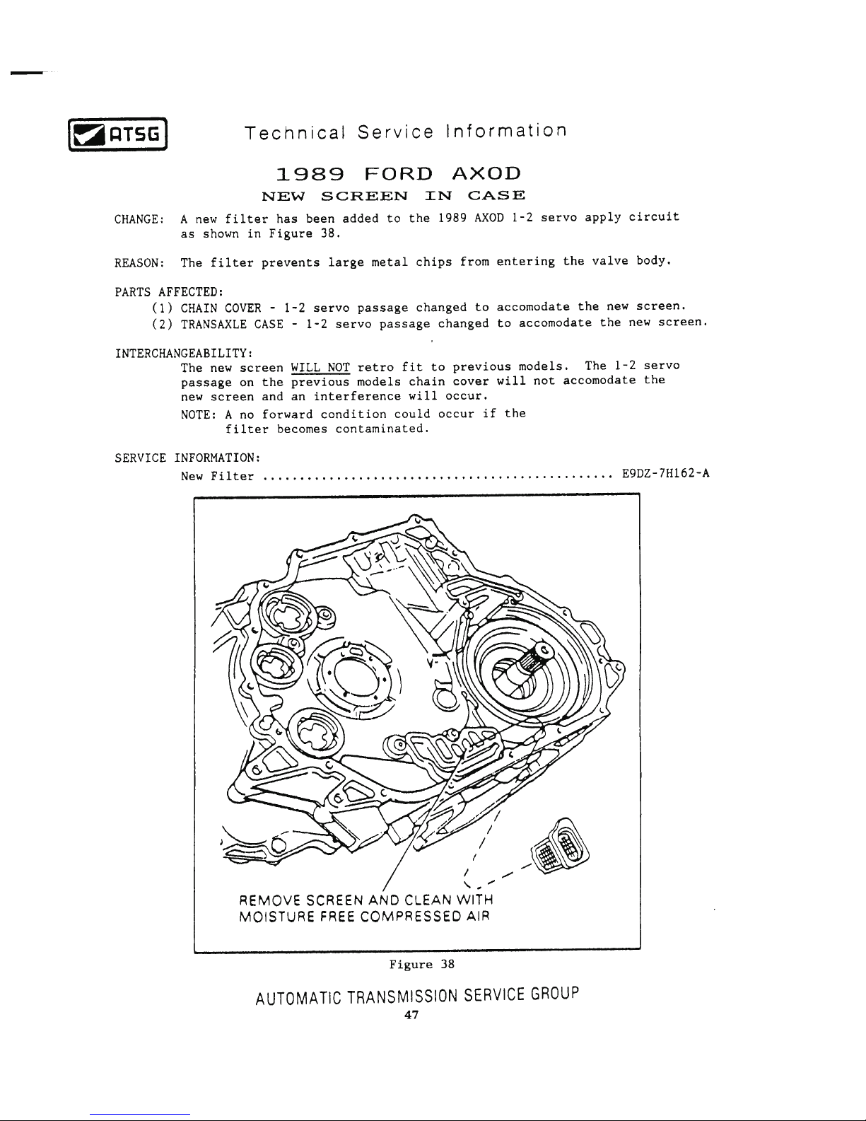
Page 48
Technical Service Information
AUTOMATIC TRANSMISSION SERVICE GROUP
48
FORD AXOD/AXODE
NEW STEEL FORWARD CLUTCH PISTON
CHANGE:
REASON:
PARTS AFFECTED:
INTERCHANGEABILITY:
SERVICE INFORMATION:
The Forward Clutch Piston material has now been changed to "Steel", instead of the previous
design aluminum piston, as shown in Figure 39.
To eliminate cracks from occuring in the seal groove and greatly improve durability.
(1)
FORWARD CLUTCH PISTON - Now manufactured out of steel, instead of aluminum, and there
are no dimensional changes on the piston (See Figure 39).
Forward Clutch Piston (All Except "SHO" Models) ........................................ F4DZ-7A262-A
Forward Clutch Piston (3.2L "SHO" Models Only) ......................................... F4DZ-7A262-B
Should be used to back service ALL previous models of the AXOD, AXODE and AX4S
transaxles. Always upgrade the forward clutch piston with the newest design steel piston using the
OEM part numbers listed below.
NEW DESIGN STEEL FORWARD CLUTCH PISTON
Figure 39
Copyright © 2000 ATSG
Page 49
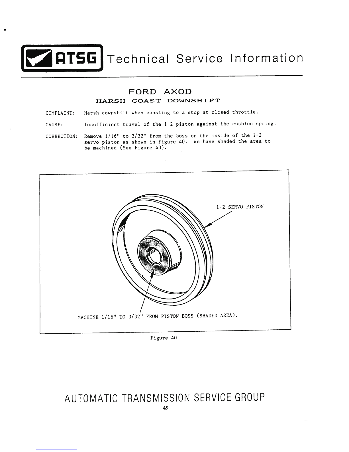
Page 50
Page 51
Page 52
Page 53
Page 54

FORD AXOD AND AXODE (AX4S)
WEAR ON OIL PUMP SHAFT AND BEARING
INTSTALLATION PROCEDURE:
SERVICE INFORMATION:
Oil Pump Drive Shaft ...................................................................................... E6DZ-7B328-A
Pump Bearing With Integral Seal .................................................................... XF2Z-7G184-AA
Pump Body Guide Pin ..................................................................................... T86P-70370-A
Valve Body Guide Pin (.271" Dia. - 2 Required) ............................................ T86P-70100-A
Valve Body Guide Pin (.262" Dia.) ................................................................. T86P-70100-B
Valve Body Guide Pin (.254" Dia.) ................................................................. T86P-70100-C
Technical Service Information
AUTOMATIC TRANSMISSION SERVICE GROUP
54
Proper alignment of the oil pump and the valve body are mandatory to prevent premature wear of the oil pump
drive shaft and the bearing assembly located in the pump housing. When re-assembling the valve body and oil
pump, use the guide pins to assure proper alignment.
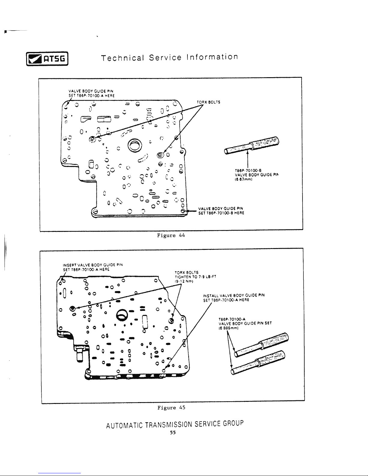
1. Position the spacer plate on the pump housing, using a new gasket.
2. Insert valve body guide pin T86P-70100-A (.271" Diameter) and valve body guide pin
T86P-70100-B (.262" Diameter), as shown in Figure 44.
3. Install two "Torx" bolts and torque to 7 to 9 ft.lb.
4. Remove both guide pins.
5. Position the spacer plate on the valve body using a new gasket.
6. Insert two valve body guide pins T86P-70100-A (.271" Diameter, as shown in Figure 45.
7. Install two "Torx" bolts and torque to 7 to 9 ft.lb.
8. Position the oil pump on the valve body using a new gasket.
9. Insert pump body guide pin T86P-70370-A and valve body guide pin T86P-70100-C which is
.245" in Diameter.
10. Install two valve body to oil pump retaining bolts and torque to 7 to 9 ft.lb.
Page 55
Page 56
FORD AXOD AND AXODE (AX4S)
EXPLODED VANE RINGS AND PUMP ROTORS
PUMP BEARING CHANGES
CHANGE:
REASON:
INTSTALLATION PROCEDURE:
SERVICE INFORMATION:
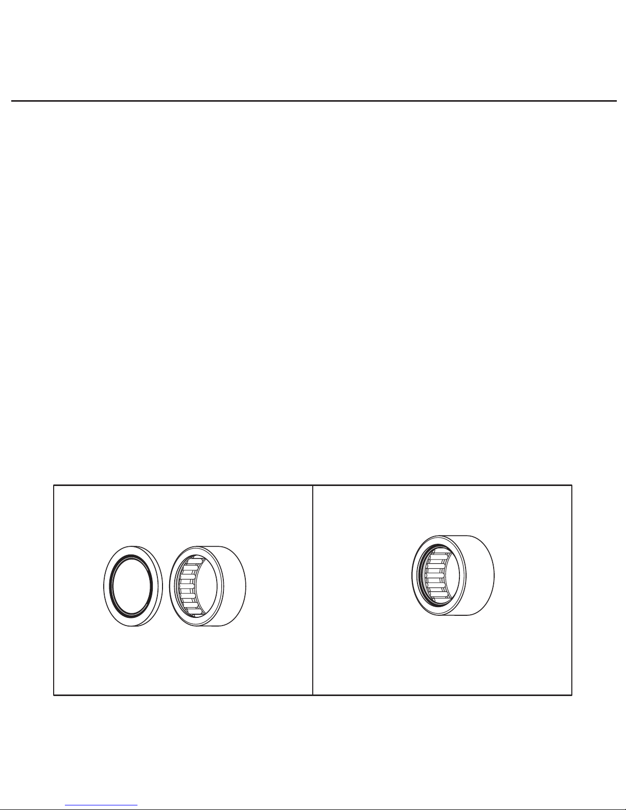
Beginning at the start of production for 2001 on all AX4S transaxles, Ford Motor Company
introduced a new design pump bearing that includes an integrated seal, as shown in Figure 47.
When this new design bearing and seal assembly went into production, it was installed with the
seal on the valve body side of the pump instead of the rotor side.
Greatly reduced pump bearing, pump rotor and vane ring failure, for much improved durability
and reliability.
Pump Bearing With Integral Seal .................................................................... XF2Z-7G184-AA
N
0
-
7
8
P
S
0
6
-
A
E
F
A
F
Outside Diameter
Is 1.000"
"NO LONGER RECOMMENDED"
Used In AXOD/AXODE
Up Through 2000
And AX4N Up Through 1999
Used In AXODE/AX4S
Beginning In 2001
Outside Diameter
Is 1.000"
OEM Part Number XF2Z-7G184-AA
"RECOMMENDED ALL MODELS"
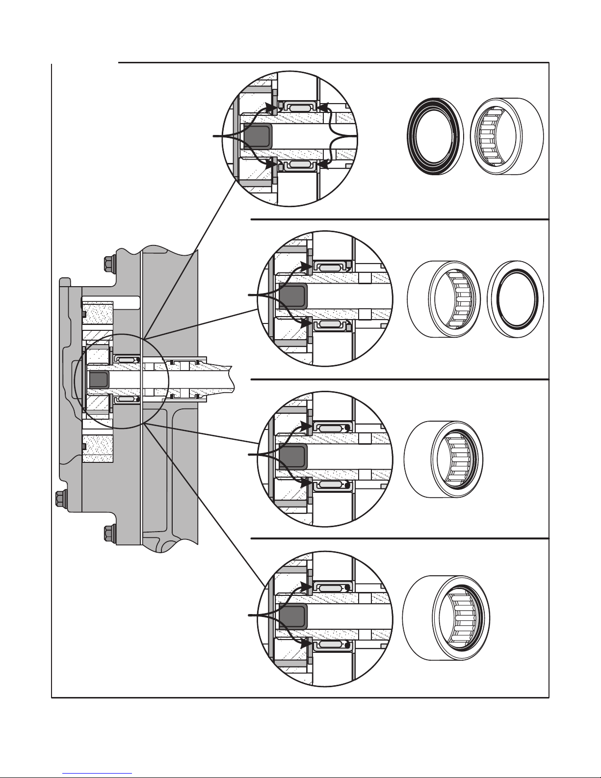
AXOD/AXODE (AX4S) - When using the 1st Design bearing with the "Nickel" Seal, install the
seal on the valve body side, with the part number facing up, as shown in Figure 48.
When using the 2nd Design bearing with the integrated seal, which is recommended, install the
bearing assembly with the integrated seal facing the valve body side. The 2nd Design Bearing and
Seal assembly will retro-fit back on all AXOD, AXODE and the AX4N up through 1999.
Figure 47
Copyright © 2001 ATSG
Technical Service Information
AUTOMATIC TRANSMISSION SERVICE GROUP
56
Page 57
Copyright © 2001 ATSG
N
0
-
7
8
P
S
0
6
-
A
E
F
A
F
First Design Bearing
And "Nickel" Seal
"Not Recommended Procedure"
When Using 1st Design
"This Is Recommended Procedure"
When Using 1st Design
AX4S 2nd Design
With Integral Seal
AX4N 2nd Design
With Integral Seal
Will Retro Back On "All"
AXOD/AXODE Models And
AX4N Models Through 1999
2000-Up Models Only
Converter
"Off" Oil
For Lube
Pump Pressure
Is Inhibited
By Seal
Oil Pump
Pressure
Is Used
For Lube
Oil Pump
Pressure
Is Used
For Lube
Oil Pump
Pressure
Is Used
For Lube
First Design Bearing
And "Nickel" Seal
Figure 48
57
AUTOMATIC TRANSMISSION SERVICE GROUP
Technical Service Information
Page 58

FORD AXOD, AXODE, AX4S
ACCUMULATOR SPRING IDENTIFICATION
COMPLAINT:
CAUSE:
CORRECTION:
SERVICE INFORMATION:
Shift quality complaints of various types, mostly harsh shift complaints, after the
transmission has been overhauled.
The accumulator springs may have been installed in incorrect positions, or the accumulator
piston shafts are scored or worn and are interfering with proper accumulator piston
movement. It is also important to insure that multiple accumulator spring applications must
have the springs wound in opposite directions of each other to avoid coil bind, as shown in
Figure 49.
Ensure that the accumulator springs have been installed in their proper locations. Refer to
Figures 49 and 50 for accumulator spring identification and position. We have also provided
you with the accumulator spring specifications in Figure 51.
Part numbers for each accumulator spring is provided in the chart in Figure 50.
Technical Service Information
AUTOMATIC TRANSMISSION SERVICE GROUP
58
Page 59
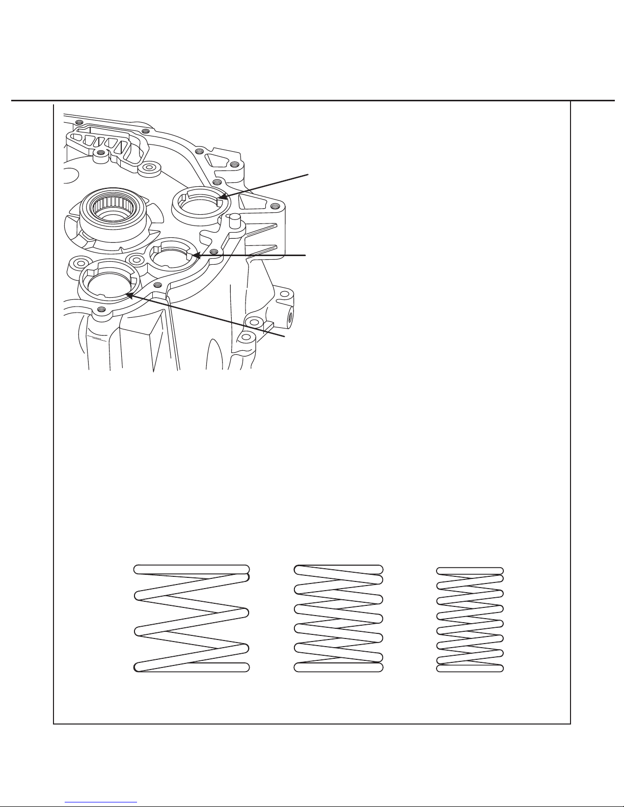
ACCUMULATOR SPRINGS
SPRINGS ARE WOUND OPPOSITE OF EACH OTHER TO AVOID COIL BIND
Copyright © 2002 ATSG
Neutral-Drive
Accumulator
Spring Location
3-4 Accumulator
Spring Location
1-2 Accumulator
Spring Location
Technical Service Information
AUTOMATIC TRANSMISSION SERVICE GROUP
59
Figure 49
Page 60
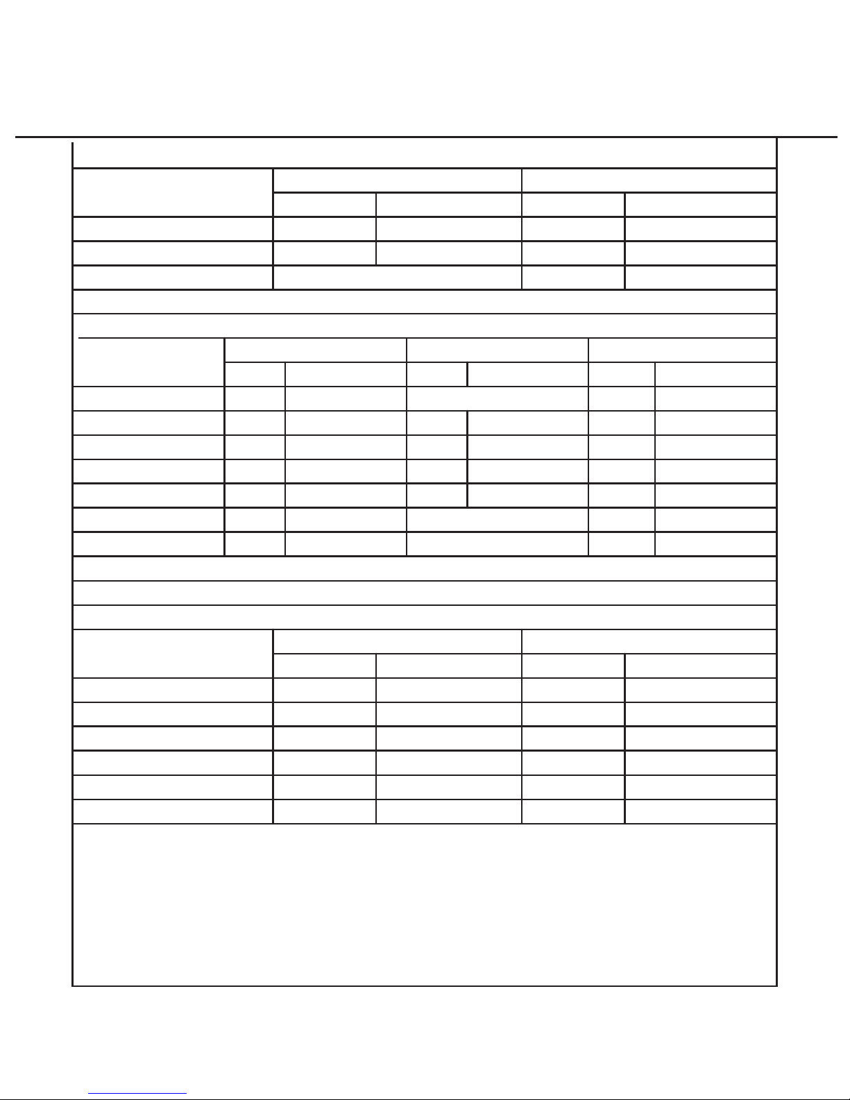
Figure 50
AXOD, AXODE, AX4S, NEUTRAL-DRIVE ACCUMULATOR SPRINGS
AXOD, AXODE, AX4S, 1-2 ACCUMULATOR SPRINGS
INNER SPRING
INNER SPRING MIDDLE SPRING
APPLICATION
APPLICATION
OUTER SPRING
OUTER SPRING
Color
Blue Orange
Orange
Green
1986-1997 "All Models"
91-94 "All Models"
95-97 "All Models"
98-01 "All Models"
1995 Windstar
1996-01 Windstar
86-90 "3.0 Liter"
88-90 "3.8 Liter"
1998-2001 "All Models"
1995-1997 Windstar Blue
Yellow
Brown
* Purple
* Purple
Brown
* Pink
Pink
Pink
Lt. Brwn
Lt. Brwn
Dk.Brwn
Dk.Brwn
Dk.Brwn
Dk.Brwn
Dk.Brwn
Dk.Brwn
Dk.Brwn
Yellow
None Used
None Used
None Used
None Used
Color
ColorColorColor
Part Number
E6DZ-7G301-A E6DZ-7G300-A
E6DZ-7G267-A
E8DZ-7G267-A
E8DZ-7G267-A
F58Z-7G267-A
F58Z-7G267-A
F58Z-7G267-A
F58Z-7G267-A
E6DZ-7G300-A
F8DZ-7G300-BA
E6DZ-7G301-A
E6DZ-7G326-A
E8DZ-7G326-A
*E8DZ-7G326-A
*E8DZ-7G326-A
* Color changed, part number remained the same.
F58Z-7G326-A
F58Z-7G326-A
F58Z-7G326-A
E8DZ-7G358-A
*E8DZ-7G358-A
E8DZ-7G358-A
E8DZ-7G358-A
Part Number
Part NumberPart NumberPart Number
1998-2001 "All Models"
AXOD, AXODE, AX4S, 3-4 ACCUMULATOR SPRINGS
INNER SPRING
APPLICATION
OUTER SPRING
Color
Green
Green
Green
Green
Green
Green
Dk. Green
Dk. Green
Dk. Green
White
Yellow
Plain
1986-1990 3.0 Liter
1991-1997 3.0 Liter
1989-1997 3.8 Liter
1988 3.8L Taurus/Sable
1988 3.8L Lincoln
ColorPart Number
E6DZ-7F288-A
E6DZ-7F288-A
E6DZ-7F288-A
E6DZ-7F288-A
E6DZ-7F288-A
E6DZ-7F288-A
E6DZ-7G266-A
E6DZ-7G266-A
E6DZ-7G266-A
E8DZ-7G266-A
E9DZ-7G266-A
F8DZ-7G266-AA
Part Number
Copyright © 2002 ATSG
Technical Service Information
AUTOMATIC TRANSMISSION SERVICE GROUP
60
Page 61
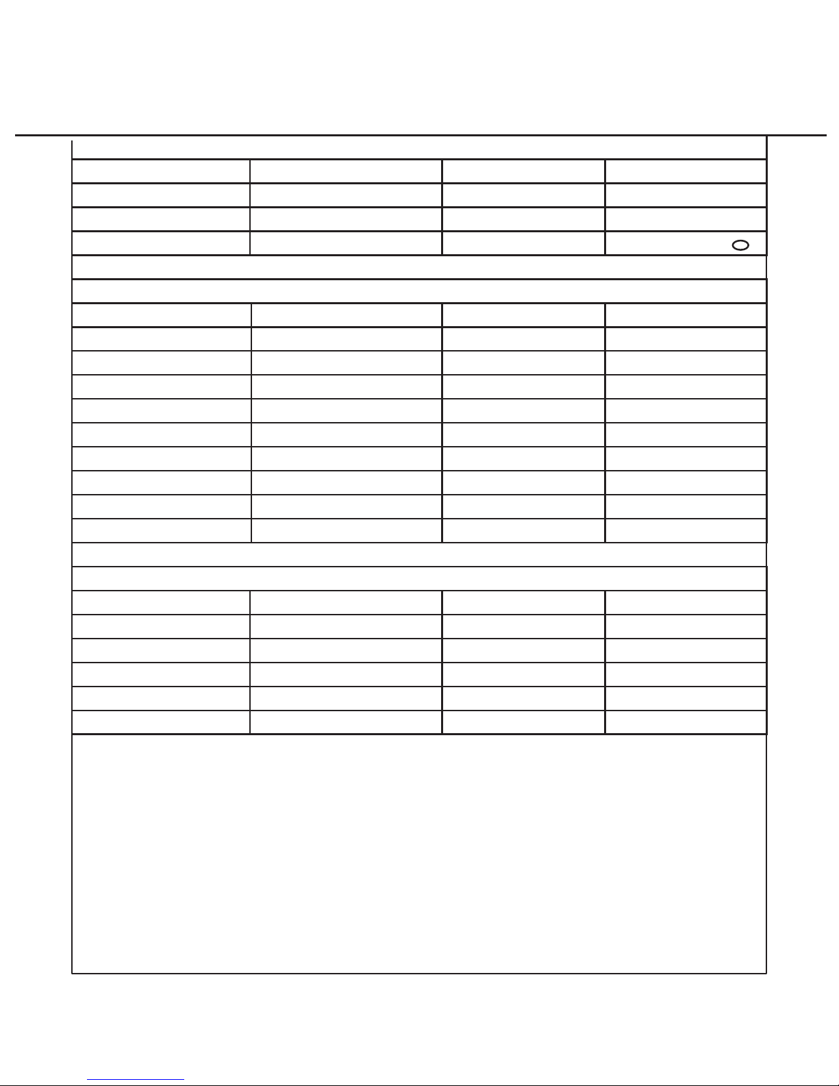
AXOD, AXODE, AX4S, NEUTRAL-DRIVE ACCUMULATOR SPRING "SPECIFICATIONS"
COLOR OUTSIDE DIAMETER FREE LENGTH WIRE DIAMETER
1.480" (37.61mm)
1.014" (25.75mm)
1.813" (46.05mm)
1.685" (42.82mm) .097" (2.48mm)
.135" (3.44mm)
1.513" (38.43mm) 1.880" (47.46mm)
Blue (Inner)
Orange (Outer)
Green (Outer)
"Ovate" Wire ( )
.898" (22.81mm) 1.439" (36.55mm) .081" (2.06mm)
1.189" (30.21mm) 1.484" (37.69mm) .092" (2.34mm)
1.175" (29.85mm) 1.690" (42.93mm) .098" (2.49mm)
1.181" (30.00mm) 1.785" (45.34mm) .099" (2.52mm)
1.183" (30.05mm) 1.735" (44.07mm) .098" (2.49mm)
AXOD, AXODE, AX4S, 3-4 ACCUMULATOR SPRING "SPECIFICATIONS"
COLOR OUTSIDE DIAMETER FREE LENGTH WIRE DIAMETER
Green (Inner)
Dk. Green (Outer)
Plain (Outer)
White (Outer)
Yellow (Outer)
1.180" (29.99mm) 1.542" (39.19mm)
.902" (22.91mm)
.902" (22.91mm)
1.507" (38.28mm)
1.507" (38.28mm)
.084" (2.15mm)
.084" (2.15mm)
1.202" (30.55mm) 1.456" (36.99mm) .106" (2.71mm)
1.216" (30.89mm) 1.443" (36.67mm) .106" (2.71mm)
1.205" (30.61mm) 1.443" (36.67mm) .107" (2.73mm)
1.559" (39.60mm) 1.450" (36.83mm) .126" (3.22mm)
1.587" (40.31mm) 1.408" (35.77mm) .126" (3.22mm)
1.595" (40.52mm) 1.490" (37.85mm) .126" (3.22mm)
AXOD, AXODE, AX4S, 1-2 ACCUMULATOR SPRING "SPECIFICATIONS"
COLOR OUTSIDE DIAMETER FREE LENGTH WIRE DIAMETER
.091" (2.30mm)
Yellow (Inner)
Brown (Inner)
Purple (Inner)
Dk. Brown (Inner)
Brown (Middle)
Pink (Middle)
Yellow (Outer)
Lt. Brown (Outer)
Dk. Brown (Outer)
Copyright © 2002 ATSG
Technical Service Information
AUTOMATIC TRANSMISSION SERVICE GROUP
61
Figure 51
Page 62
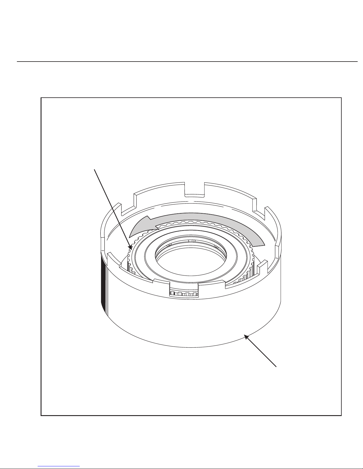
FORD AXOD, AXODE (AX4S)
LOW SPRAG
HOLD
OVERDRIVE DRUM
FREEWHEEL
LOW SPRAG
OUTER RACE
THE LOW SPRAG OUTER RACE MUST FREEWHEEL COUNTER CLOCKWISE
AND LOCK CLOCKWISE WHEN HOLDING THE OVERDRIVE DRUM
E
W
HE
E
E
R
L
F
Technical Service Information
AUTOMATIC TRANSMISSION SERVICE GROUP
62
Figure 52
Copyright © 2002 ATSG
Page 63
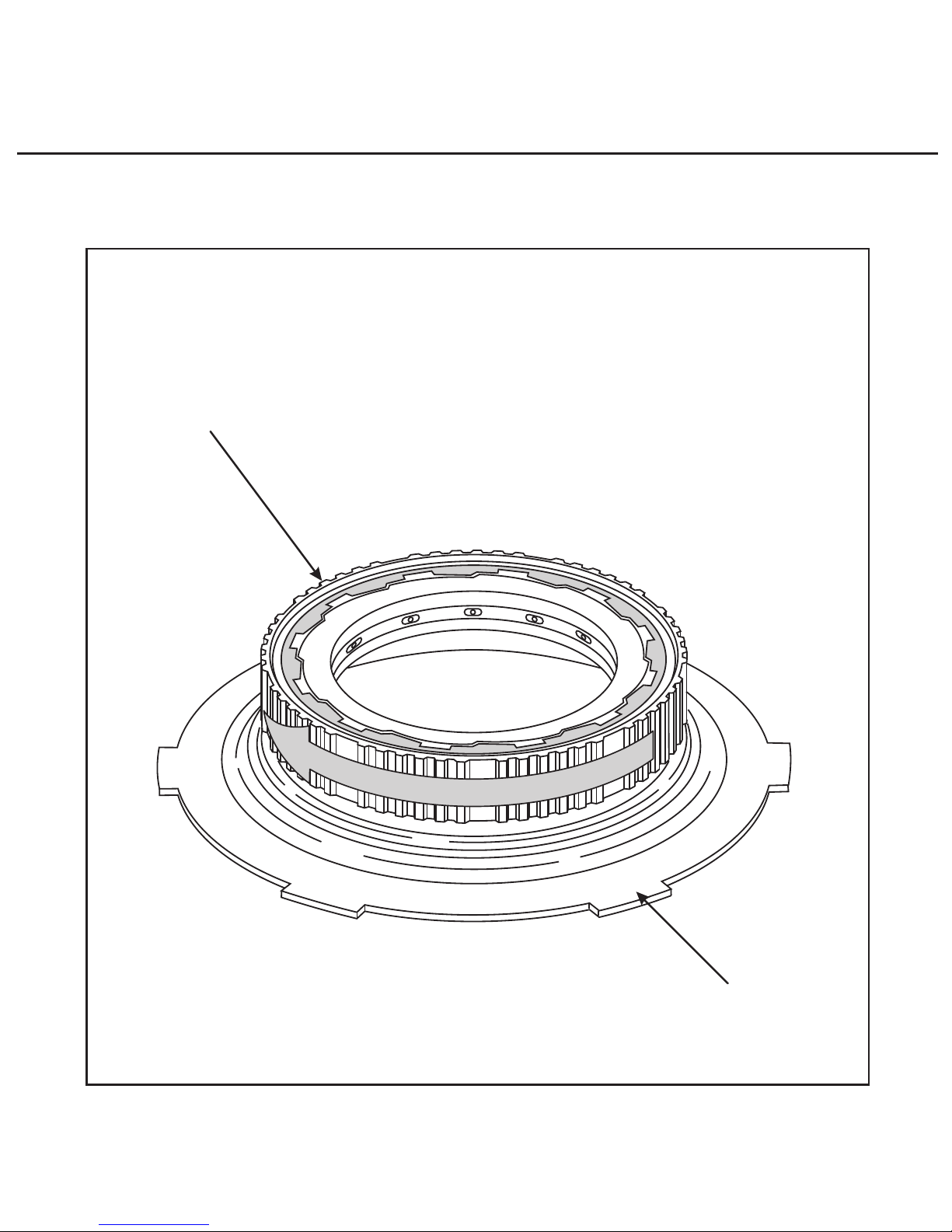
HOLD
INNER RACE
FREEWHEEL
OUTER RACE
FORD AXOD, AXODE (AX4S)
3RD ROLLER CLUTCH
THE 3RD ROLLER CLUTCH OUTER RACE MUST FREEWHEEL
CLOCKWISE AND LOCK COUNTER CLOCKWISE WHEN THE
3RD ROLLER CLUTCH INNER RACE IS HELD
F
R
L
E
E
E
E
W
H
Technical Service Information
AUTOMATIC TRANSMISSION SERVICE GROUP
63
Figure 53
Copyright © 2002 ATSG
Page 64

Technical Service Information
AUTOMATIC TRANSMISSION SERVICE GROUP
64
Copyright © 2002 ATSG
FORD AXOD/AXODE
FORWARD CLUTCH WAVE PLATE CHANGE
CHANGE:
REASON:
PARTS AFFECTED:
INTERCHANGEABILITY:
SERVICE INFORMATION:
The Forward Clutch Wave Plate has been changed three times since the transaxle was introduced
in model year 1986.
To help improve garage shift engagements and to help improve the 4-2 and 3-2 forced downshifts.
(1)
FORWARD CLUTCH WAVE PLATE:
1ST DESIGN - Has 4 external teeth, an inside diameter of 4.715", material thickness of .062", and
was used from 1986-1988. Refer to Figure 54.
2ND DESIGN - Has 21 external teeth, inside diameter of 4.730", material thickness of .075",
identified with letter "X" stamped on 1 tooth, and was used from 1989-1991. (See Figure 55).
3RD DESIGN - Has 21 external teeth, inside diameter of 4.930", material thickness of .083",
identified with letter "A" stamped on 1 tooth, used in 1992 and later models. (See Figure 56).
The 2nd design forward clutch wave plate will retro-fit back to all previous models and is the
recommended wave plate for the AXOD transaxle.
The 3rd design forward clutch wave plate was associated with a change in the entire forward clutch
pack and should be used Only with the later design forward clutch pack, which are a larger inside
diameter.
Forward Clutch Wave Plate (1st Design) ........................................................... E6DZ-7E085-B
Forward Clutch Wave Plate (1st Design) ........................................................... F0DZ-7E085-A
Forward Clutch Wave Plate (1st Design) ........................................................... F2DZ-7E085-A
Page 65
Technical Service Information
AUTOMATIC TRANSMISSION SERVICE GROUP
65
Figure 54
Copyright © 2002 ATSG
4 External Teeth
Inside Diameter 4.715"
Material Is .062" Thick
Part Number E6DZ-7E085-B
FORD AXOD
FORWARD CLUTCH WAVE PLATE
USED 1986-1988
Page 66
Technical Service Information
AUTOMATIC TRANSMISSION SERVICE GROUP
66
Figure 55
Copyright © 2002 ATSG
21 External Teeth
Inside Diameter 4.730"
Material Is .075" Thick
I.D. Stamped "X" On 1 Tooth
Part Number F0DZ-7E085-A
FORD AXOD
FORWARD CLUTCH WAVE PLATE
USED 1989-1991
X
Page 67
Technical Service Information
AUTOMATIC TRANSMISSION SERVICE GROUP
67
Figure 56
Copyright © 2002 ATSG
FORD AXOD
FORWARD CLUTCH WAVE PLATE
USED 1992 AND LATER
21 External Teeth
Inside Diameter 4.930"
Material Is .083" Thick
I.D. Stamped "A" On 1 Tooth
Part Number F2DZ-7E085-A
A
Page 68

Technical Service Information
AUTOMATIC TRANSMISSION SERVICE GROUP
Copyright © 2002 ATSG
68
FORD AXOD/AXODE
FORWARD CLUTCH PACK CHANGE
LOW SPRAG OUTER RACE CHANGE
CHANGE:
REASON:
PARTS AFFECTED:
INTERCHANGEABILITY:
SERVICE INFORMATION:
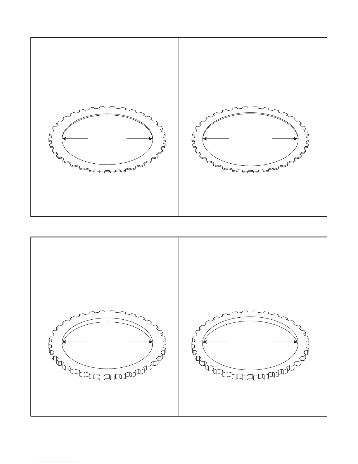
Beginning at start of production for 1992 models, all AXODE transaxles were built with a revised
low sprag outer race that required revisions on the forward clutches, both lined and steel plates, a
new pressure plate and "Wave" plate.
Improved durability and reliability of the low sprag outer race.
(1)
(2)
(3)
(4)
(5)
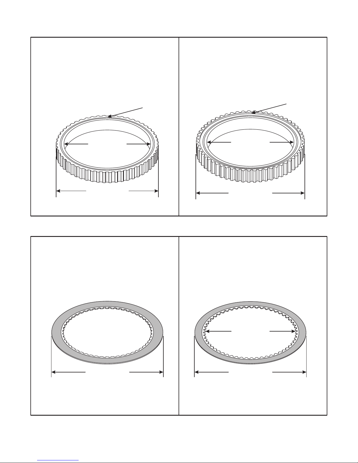
LOW SPRAG OUTER RACE - The outer diameter of the race was increased from 4.575" to
4.825", and the width of the race was increased from .600" to .725", as shown in Figure 57. The
Inside Diameter of the sprag race Did Not Change.
FORWARD CLUTCH FRICTION PLATES - Have an increased amount of teeth to 57 Teeth from
the previous 52 Teeth, to accommodate the increased diameter of the sprag outer race, as shown in
Figure 58.
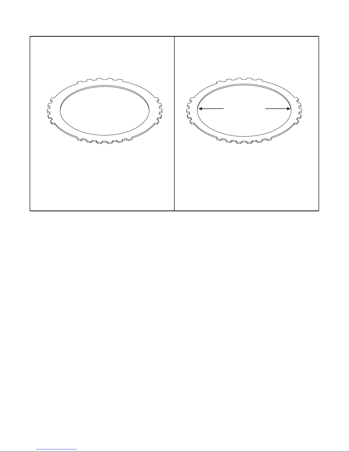
FORWARD CLUTCH STEEL PLATES - Have an increased inside diameter to 4.920" from the
previous 4.720", to accommodate the increased diameter of the sprag outer race, as shown in
Figure 59.
FORWARD CLUTCH PRESSURE PLATE - Has an increased inside diameter to 4.930" from the
previous 4.730", to accommodate the increased diameter of the sprag outer race, as shown in
Figure 60.
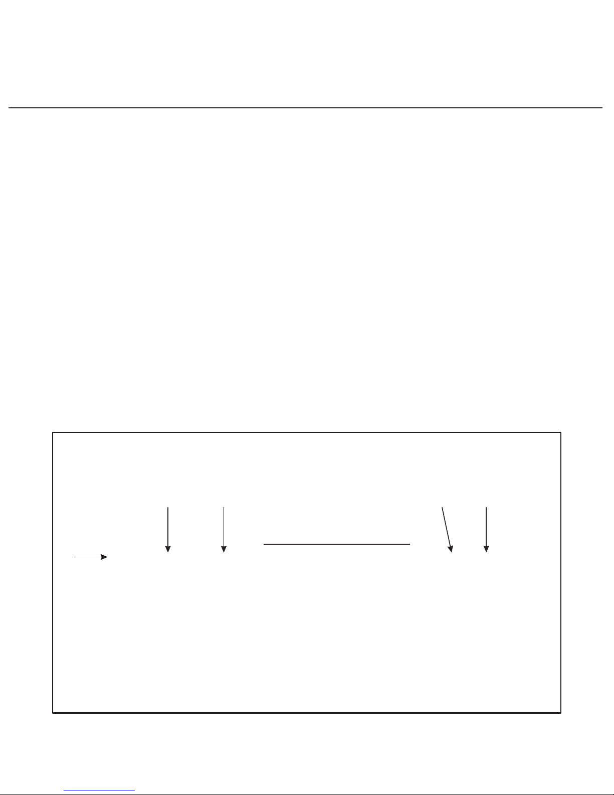
FORWARD CLUTCH "WAVE" PLATE - Has an increased inside diameter to 4.930" from the
previous 4.730", to accommodate the increased diameter of sprag outer race (See Figure 61).
None of the parts listed above are interchangeable with previous design parts. If the sprag outer
race is upgraded to the latest design, the forward clutch components must also be upgraded to the
latest design level.
When all of the above parts are changed as a service package, they will retro-fit back to all previous
model AXOD/AXODE transaxles.
Forward Clutch Friction Plates (2nd Design) .................................................... F2DZ-7B164-A
Forward Clutch Steel Plates (2nd Design) ......................................................... F2DZ-7B442-A
Forward Clutch "Wave" Plate (2nd Design) ...................................................... F2DZ-7E085-A
Forward Clutch Pressure Plate (2nd Design) .................................................... F2DZ-7B066-A
Forward Clutch Overhaul Kit (Includes Low Sprag Outer Race) ..................... F2DZ-7D171-A
Page 69
Copyright © 2002 ATSG
Copyright © 2002 ATSG
FORD AXOD/AXODE
LOW SPRAG OUTER RACE
USED 1989-1991
FORD AXOD/AXODE
FORWARD FRICTION PLATE
USED 1989-1991
FORD AXODE (AX4S)
LOW SPRAG OUTER RACE
USED 1992 AND LATER
FORD AXODE (AX4S)
FORWARD FRICTION PLATE
USED 1992 AND LATER
AUTOMATIC TRANSMISSION SERVICE GROUP
Technical Service Information
69
57 Teeth52 Teeth
4.575" Overall
Outside Diameter
5.750" Overall
Outside Diameter
5.750" Overall
Outside Diameter
Increased
Inside Diameter
4.825" Overall
Outside Diameter
"Step" On
Both Sides
"Flat" On
Both Sides
Inside Diameter
Did Not Change
Inside Diameter
Did Not Change
Figure 58
Figure 57
Page 70
AUTOMATIC TRANSMISSION SERVICE GROUP
Technical Service Information
70
Figure 60
Figure 59
FORD AXOD/AXODE
FORWARD STEEL PLATE
USED 1989-1991
FORD AXOD/AXODE
FORWARD STEEL PLATE
USED 1989-1991
FORD AXODE (AX4S)
FORWARD STEEL PLATE
USED 1992 AND LATER
FORD AXODE (AX4S)
FORWARD STEEL PLATE
USED 1992 AND LATER
34 Teeth
34 Teeth
34 Teeth
34 Teeth
4.920"
Inside Diameter
4.930"
Inside Diameter
4.720"
Inside Diameter
4.730"
Inside Diameter
Copyright © 2002 ATSG
Copyright © 2002 ATSG
Page 71
AUTOMATIC TRANSMISSION SERVICE GROUP
Technical Service Information
71
Figure 61
21 External Teeth
Inside Diameter 4.730"
Material Is .075" Thick
I.D. Stamped "X" On 1 Tooth
Part Number F0DZ-7E085-A
21 External Teeth
Inside Diameter 4.930"
Material Is .083" Thick
I.D. Stamped "A" On 1 Tooth
Part Number F2DZ-7E085-A
FORD AXOD/AXODE
FORWARD "WAVE" PLATE
USED 1989-1991
FORD AXODE (AX4S)
FORWARD "WAVE" PLATE
USED 1992 AND LATER
A
X
Increased
Inside Diameter
Copyright © 2002 ATSG
Page 72

Technical Service Information
AUTOMATIC TRANSMISSION SERVICE GROUP
Copyright © 2002 ATSG
72
FORD AXOD/AXODE
NEW DESIGN INPUT PLANETARY CARRIER
AND SUN GEAR AND SHELL ASSEMBLY
CHANGE:
REASON:
PARTS AFFECTED:
INTERCHANGEABILITY:
SERVICE INFORMATION:
Beginning at start of production for 1992 models, all AXODE transaxles were built with a new
caged needle bearing added to the shaft on the Input Planetary Carrier, which also required a
change on the Sun Gear and Shell assembly.
To better stabilize the sun gear and shell assembly for improved durability and reliability, of
center gearbox concerns.
(1)
(2)
INPUT PLANETARY CARRIER - New caged needle Bearing added to the shaft on the Input
Planetary Carrier, as shown in Figure 62.
SUN GEAR AND SHELL ASSEMBLY - Single bushing is now located in front of the lube holes
in the sun gear, and the area behind is now machined to accommodate the new caged needle
bearing, as shown in Figure 63.
When you order an Input Planetary Carrier and/or a Sun Gear and Shell assembly from OEM, they
will automatically supercede to the new service package part number F4DZ-7A398-A, which
includes both of the new design parts listed above.
The new design parts listed above will back service all previous models, but must be used together
as a set.
The new design parts are not compatable with the previous design parts.
Page 73

Copyright © 2002 ATSG
NEW DESIGN INPUT PLANETARY CARRIER
Caged Needle Bearing Added
On The Shaft Located Here
AUTOMATIC TRANSMISSION SERVICE GROUP
Technical Service Information
73
Figure 62
Page 74

AUTOMATIC TRANSMISSION SERVICE GROUP
Technical Service Information
74
Figure 63
PREVIOUS DESIGN SUN GEAR AND SHELL
NEW DESIGN SUN GEAR AND SHELL
Copyright © 2002 ATSG
Bushing Placement
New Placement Of Bushing
This Area Now Machined To
Accommodate New Caged Bearing
Page 75
75
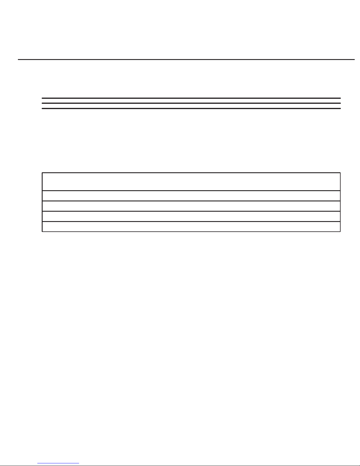
Figure 64
Copyright © 2002 ATSG
Technical Service Information
AUTOMATIC TRANSMISSION SERVICE GROUP
FORD AXOD/AXOD-E
NO MOVEMENT OR NO CONVERTER CLUTCH
COMPLAINT:
CAUSE:
CORRECTION:
SERVICE INFORMATION:
OIL PUMP DRIVE SHAFT
A
B C D E
NOTE: THERE ARE ADJOINING HOLES ON THE OPPOSITE SIDE
OF THE OIL PUMP DRIVE SHAFT THAT ARE NOT ILLUSTRATED.
APPLY AIR PRESSURE INTO HOLE "D" AND ENSURE THAT
AIR PRESSURE ESCAPES THROUGH HOLE "C" ONLY.
APPLY AIR PRESSURE INTO HOLE "A" AND ENSURE THAT
AIR PRESSURE ESCAPES THROUGH HOLES "B"&"E" ONLY.
Before and/or after rebuild, the vehicle exhibits one of the following conditions:
1. "No Movement" in forward or reverse.
2. "No Converter Clutch" apply at any speed.
The cause may be, one of the following:
1. The converter feed passage in the Oil Pump Drive Shaft blocked with debris or
was not machined properly to allow converter feed oil to enter the converter.
2. The Oil Pump Drive Shaft leaking or not machined properly, allowing converter
feed passage and converter release passage to be connected.
Refer to Figure 64 to check the Oil Pump Drive Shaft, and clean or replace as necessary.
NOTE: We have seen some replacement shafts, both reman and new that were leaking
between the converter apply and release passages.
Oil Pump Drive Shaft (AXOD/AXODE) ................................................. E6DZ-7B328-A
Page 76
Technical Service Information
AUTOMATIC TRANSMISSION SERVICE GROUP
Copyright © 2002 ATSG
76
THE REMAINDER OF THIS MANUAL WILL BE
DEDICATED TO THE AXODE TRANSAXLE
OIL PUMP CHECKBALL LOCATION CHANGES
FORD AXODE
"Early" 1991 Only - Uses 5 checkballs in the locations shown in Figure 65. Use chart above to determine
Early or Late transaxle by serial number.
"Late" 1991 Only - Uses 4 checkballs in the locations shown in Figure 65. Use chart above to determine
Early or Late transaxle by serial number.
1992-1998 Only - Uses 4 checkballs but in different locations, as shown in Figure 66. B-13 checkball
was eliminated and B-2 checkball was added.
1999-2002 Only - Uses 3 checkballs in the locations shown in Figure 66. B-5 checkball was eliminated.
Up To And Including
Serial Number
Vehicle Line
1991 Taurus/Sable 3.8L 54553
39653
10936
195343
PNA-EA
PNA-EC
PNA-EB
PNA-EE
1991 Continental 3.8L
1991 All Police 3.8L
1991 Taurus/Sable 3.0L
Model Code
Page 77
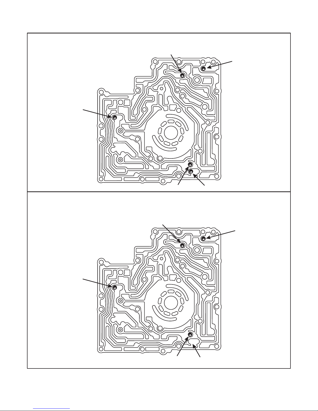
Copyright © 2002 ATSG
CHECKBALL LOCATIONS "EARLY" 1991 "ONLY"
CHECKBALL LOCATIONS "LATE" 1991 "ONLY"
AUTOMATIC TRANSMISSION SERVICE GROUP
Technical Service Information
77
Figure 65
X
X
X
CHECKBALL LOCATIONS "LATE" 1991 "ONLY"
B-5
B-13
B-13
B-11
B-10
B-12
B-12 Eliminated
B-5
B-11
B-10
Page 78
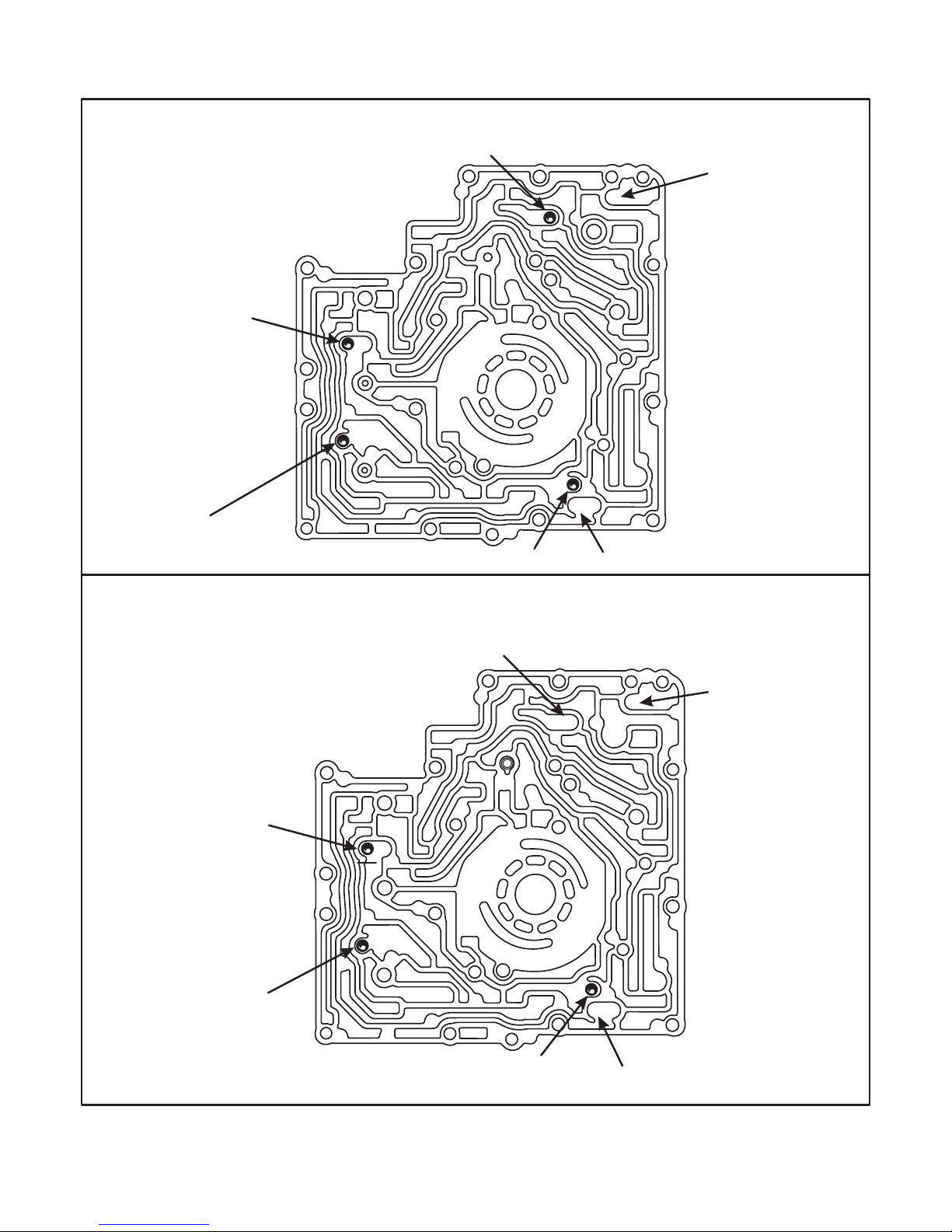
AUTOMATIC TRANSMISSION SERVICE GROUP
Technical Service Information
78
Figure 66
Copyright © 2002 ATSG
CHECKBALL LOCATIONS 92-98 MODELS "ONLY"
X
X
X
X
X
CHECKBALL LOCATIONS 1999 AND LATER "ONLY"
B-5
B-5 Eliminated
B-13 Eliminated
B-11
B-11
B-2 Checkball
Added
B-2
B-10
B-10
B-12 Still Not Used
B-13 Still Not Used
B-12 Still Not Used
Page 79
79
Figure 67
Copyright © 2002 ATSG
Technical Service Information
AUTOMATIC TRANSMISSION SERVICE GROUP
FORD AXOD/AXOD-E
CONVERTER TURBINE SPLINES CHANGE
FROM 23 TEETH TO 25 TEETH
CHANGE:
REASON:
PARTS AFFECTED:
INTERCHANGEABILITY:
Two "Notches" 180 Degrees
Apart Indicate a 25 Tooth
Turbine Hub
INNER VIEW OF
CONVERTER HUB
OPENING
CONVERTER
STAMP CODE
(23 TEETH)
18 Or 36 19 Or 45
28 Or 42
29 Or 39
30 Or 44
31 Or 41
24 Or 37
25 Or 38
26 Or 43
27 Or 40
CONVERTER
STAMP CODE
(25 TEETH)
1994 Models Could Be Either
1993-Back Models: Are 23 Spline From OEM
1995-Up Models: Are 25 Spline From OEM
"Do Not" Use I.D. Stamp Code For
Identification If Converter Has Been
Re-Manufactured
Beginning on December 20, 1993, for the 1994 production schedule, Ford Motor Co. changed the
converter turbine splines and the turbine shaft splines to 25 teeth from previous 23 splines.
Improved durability for higher torque applications.
(1)
(2)
TORQUE CONVERTER - Converter turbine splines changed from 23 splines to 25 splines. To
identify this change, the converter "Stamp Code" was changed. Refer to the chart found in Figure
67 for identification, if the converter has not been rebuilt.
TURBINE SHAFT - Splines changed from 23 splines to 25 splines. Count the number of splines
on turbine shaft for positive identification.
If replacement of either torque converter and/or turbine shaft is necessary, ensure that equal
number of splines exist on the mating parts.
CAUTION: It is possible to install a 25 Spline converter onto a 23 Spline turbine shaft. If this
occurs, the vehicle will have a "No Movement" condition and after the engine is started will
usually twist off the stator shaft (Drive Sprocket Support).
Page 80
Technical Service Information
AUTOMATIC TRANSMISSION SERVICE GROUP
Copyright © 2002 ATSG
80
VALVE BODY BORE NUMBERS
AND VALVE IDENTIFICATION
FORD AXODE
VALVE BODY
FRONT VIEW
VALVE BODY
REAR VIEW
On this page we have assigned numbers to all of the valve body bores and re-drawn the valves and springs and
placed them in their proper locations, with each valve oriented properly and the function identified, as shown on
the following pages. Most of the manuals presently in print are wrong.
USE THIS MANUAL TO PROPERLY ASSEMBLE THE AXODE (AX4S) VALVE BODY
Figure 68
Page 81
Copyright © 2002 ATSG
AUTOMATIC TRANSMISSION SERVICE GROUP
Technical Service Information
81
Figure 69
VALVE BODY BORE NUMBERS
AND VALVE IDENTIFICATION
FORD AXODE
Valve Body
Bore Number
32
33
33
34
34
35
36
36
37
37
37
38
38
39
40
41
42
43
44
45
45
46
47
1
2
3
4
5
6
7
8
9
10
11
12
13
14
15
16
17
18
19
20
21
22
23
Valve Number Description
Pressure Failsafe Valve
Backout Valve (Found In Early 1991 Only)
Backout Valve (Found In Late 1991 To Current Models)
Accumulator Regulator Valve Plunger
Converter Clutch Control Valve Plunger
Converter Clutch Control Valve
Main Regulator Boost Valve Sleeve
Main Regulator Boost Valve
Converter Clutch Regulator Valve
Shift Solenoid Regulator Valve
2-3 Servo Regulator Valve
Manual Valve
2-3 Shift Valve
1-2 Shift Valve
3-4 Shift Valve
Forward Clutch Control Valve
Pull-In Control Valve
Neutral/Drive Engagement Control Valve
3-2 Control Valve (If Retainer Breaks, 3-Neutral Shift)
Intermediate Clutch Shuttle Valve
Main Regulator Valve (Note Direction Of Spring Seat)
Accumulator Regulator Valve
1-2 Capacity Modulator Valve
Page 82

AUTOMATIC TRANSMISSION SERVICE GROUP
Technical Service Information
82
Figure 70
Copyright © 2002 ATSG
Early 1991 Only
1. PRESSURE FAILSAFE VALVE
2. BACKOUT VALVE (EARLY 1991)
3. BACKOUT VALVE (CURRENT)
4. ACCUMULATOR REGULATOR VALVE PLUNGER
5. ACCUMULATOR REGULATOR VALVE
6. 1-2 CAPACITY MODULATOR VALVE
Page 83

83
Figure 71
Copyright © 2002 ATSG
AUTOMATIC TRANSMISSION SERVICE GROUP
Technical Service Information
7. BYPASS CLUTCH CONTROL PLUNGER
8. BYPASS CLUTCH CONTROL VALVE
9. MAIN REGULATOR BOOST VALVE SLEEVE
10. MAIN REGULATOR BOOST VALVE
11. MAIN REGULATOR VALVE
12. CONVERTER REGULATOR VALVE
13. SOLENOID REGULATOR VALVE
Page 84

84
Figure 72
AUTOMATIC TRANSMISSION SERVICE GROUP
Technical Service Information
14. MANUAL VALVE
15. 2-3 SHIFT VALVE
Copyright © 2002 ATSG
Page 85

Copyright © 2002 ATSG
AUTOMATIC TRANSMISSION SERVICE GROUP
Technical Service Information
85
Figure 73
16. 1-2 SHIFT VALVE
17. INTERMEDIATE CLUTCH SHUTTLE VALVE
18. 3-4 SHIFT VALVE
19. FORWARD CLUTCH CONTROL VALVE
Page 86
86
Copyright © 2002 ATSG
AUTOMATIC TRANSMISSION SERVICE GROUP
Technical Service Information
20. PULL-IN CONTROL VALVE
21. 3-2 CONTROL VALVE
22. N/D ENGAGEMENT CONTROL VALVE
23. 2-3 SERVO REGULATOR VALVE
Figure 74
Eliminated In 1999
And Later
Page 87

87
Figure 75
Copyright © 2002 ATSG
AUTOMATIC TRANSMISSION SERVICE GROUP
Technical Service Information
20. PULL-IN CONTROL VALVE
21. 3-2 CONTROL VALVE
Revised Spring
Retainer Clip
F1DZ-7F194-A
Valve Body
Front View
FORD AXODE
3-NEUTRAL KICKDOWN SHIFT
COMPLAINT:
CAUSE:
CORRECTION:
A delayed shift may occur during 3-2 forced downshifts, or "Kickdown", and/or the
transaxle will shift to neutral during the 3-2 kickdown.
The cause may be, a broken spring retainer clip between the pull-in control valve spring and
the 3-2 control valve spring, as shown in Figure 75.
Replace the spring retainer clip with OEM part number F1DZ-7F194-A, as shown in Figure
75.
Page 88
88
Figure 76
AUTOMATIC TRANSMISSION SERVICE GROUP
Technical Service Information
Copyright © 2002 ATSG
OEM Part Number Code Application
Ford Taurus SHO
Ford Taurus/Sable
Lincoln Continental
Ford Taurus/Sable
Ford Taurus/Sable
Ford Taurus/Sable
Ford Windstar
Ford Windstar
Ford Windstar
Ford Windstar
Ford Windstar (W/VB's XD29-AB/AC/BB)
Ford Taurus/Sable
Model Year Engine
F5DZ-7Z490-B
F5DZ-7Z490-C
F5DZ-7Z490-D
F58Z-7Z490-A
F58Z-7Z490-B
F6DZ-7Z490-FB
F68Z-7Z490-A
F88Z-7Z490-AA
XF2Z-7Z490-AA
XF2Z-7Z490-AA
YF1Z-7Z490-AA
3.2L
3.0L
3.0L
3.0L
3.0L
3.0L/3.8L
3.0L/3.8L
3.0L
3.8L
3.8L
3.8L
3.8L
1994-1995
1994-1995
1994-1995
1996-1998
1996-1997
1994
1995
1995
1998
1999
1999
2000-2002
31
40
41
58
98
99
99
00
53
42(97)*
47(67)*
OEM Part Number Code Application
Lincoln Continental
Ford Windstar
Ford Windstar, Ford Taurus/Sable
Ford Windstar, Ford Taurus/Sable
Ford Taurus/Sable and Windstar
Model Year Engine
F5DZ-7R167-A
F58Z-7R167-A
X2FZ-7R167-AA
AH
1994 3.8L
3.8L
3.0L
3.0L/3.8L
ALL1994-1995
1996-1998
1999-2002
1995-1998
51
99
AX4S BONDED PUMP SPACER PLATES
AX4S BONDED VALVE BODY SPACER PLATES
OEM Part Number F6DZ-7Z490-FB has a "42" code and replaces the "97" code, as the "97"
code spacer plate is no longer available.
OEM Part Number F68Z-7Z490-A has a "47" code and replaces the "67" code, as the "67" code
spacer plate is no longer available.
AXODE (AX4S)
PUMP AND VALVE BODY SPACER PLATE IDENTIFICATION
CAUTION: Part Numbers may change or supercede without notice.
Page 89
Copyright © 2002 ATSG
AUTOMATIC TRANSMISSION SERVICE GROUP
Technical Service Information
89
Figure 77
SPECIAL NOTE:
Color Of The I.D. Stripe May
Vary From Different Suppliers
1991-Up Pump Spacer
Plate To Valve Body
F1DZ-7A136-A
1991-Up Pump Spacer
Plate To Pump Body
F3DZ-7G331-A
(Green I.D. Stripe)
(Green I.D. Stripe)
AXODE (AX4S) PUMP GASKETS
Page 90
90
Copyright © 2002 ATSG
AUTOMATIC TRANSMISSION SERVICE GROUP
Technical Service Information
Figure 78
1991-1998 Valve Body Spacer
Plate To Chain Cover
F1DZ-7C155-A
1991-1998 Valve Body Spacer
Plate To Valve Body
F1DZ-7D100-A
(Orange I.D. Stripe)
(Orange I.D. Stripe)
SPECIAL NOTE:
Color Of The I.D. Stripe May
Vary From Different Suppliers
AXODE (AX4S) 1991-1998
V.B. GASKETS
Page 91
91
Figure 79
Copyright © 2002 ATSG
AUTOMATIC TRANSMISSION SERVICE GROUP
Technical Service Information
1999-2002 Valve Body Spacer
Plate To Chain Cover
XF2Z-7C155-AA
1999-2002 Valve Body Spacer
Plate To Valve Body
XF2Z-7D100-AA
(Yellow I.D. Stripe)
(Blue I.D. Stripe)
SPECIAL NOTE:
Color Of The I.D. Stripe May
Vary From Different Suppliers
AXODE (AX4S) 1999-2002
V.B. GASKETS
Page 92
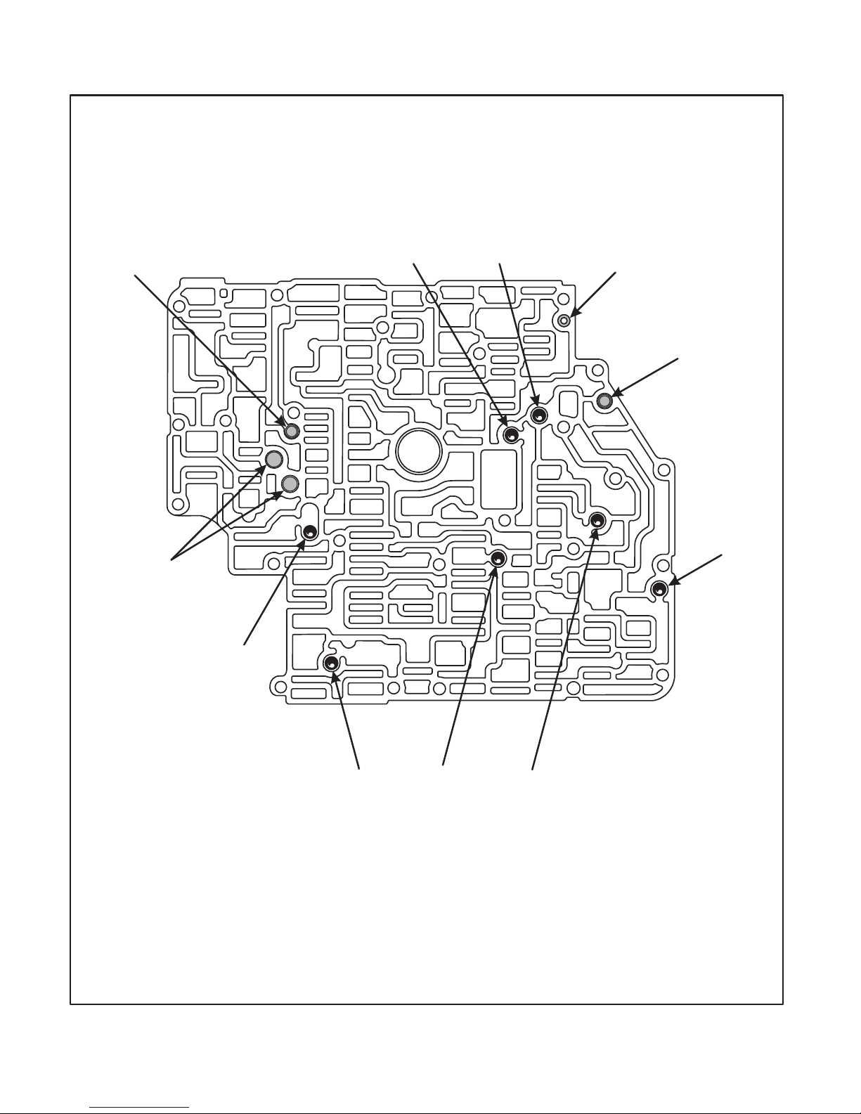
92
Figure 80
AUTOMATIC TRANSMISSION SERVICE GROUP
Technical Service Information
Copyright © 2002 ATSG
NO. 4 NO. 1 NO. 6
NO. 3
NO. 7NO. 9
Alignment
Dowel
Relief
Valve
Relief
Valve
Filters
NO. 8
AXODE (AX4S) 1991-1992 ONLY
CHECKBALL AND RELIEF VALVE LOCATIONS
Page 93
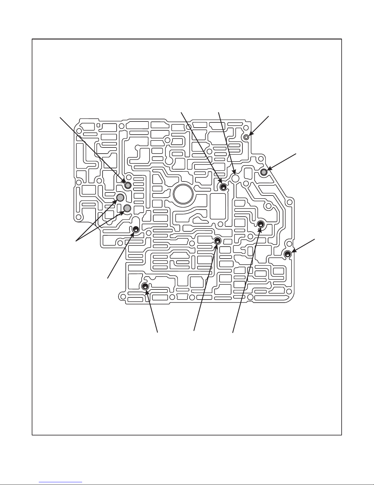
Copyright © 2002 ATSG
AUTOMATIC TRANSMISSION SERVICE GROUP
Technical Service Information
93
Figure 81
X
NO. 4 NO. 1 NO. 6
NO. 3
NO. 7 Checkball
Eliminated 1993
NO. 9
Alignment
Dowel
Relief
Valve
Relief
Valve
Filters
NO. 8
AXODE (AX4S) 1993-1998
CHECKBALL AND RELIEF VALVE LOCATIONS
Page 94
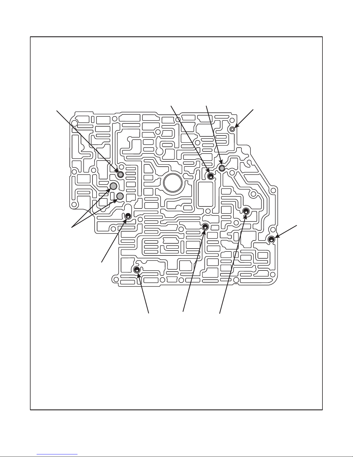
94
Copyright © 2002 ATSG
AUTOMATIC TRANSMISSION SERVICE GROUP
Technical Service Information
Figure 82
AXODE (AX4S) 1999-2002
CHECKBALL AND RELIEF VALVE LOCATIONS
NO. 4 NO. 1 NO. 6
NO. 3
NO. 9
Alignment
Dowel
Relief
Valve
Relief
Valve
Filters
NO. 8
Page 95

95
Figure 83
Copyright © 2002 ATSG
AUTOMATIC TRANSMISSION SERVICE GROUP
Technical Service Information
PREMATURE PLANETARY FAILURE
ORIGINAL
ORIGINAL
REAR
LUBE
TUBE
DIFF/SPEEDO
LUBE TUBE
AXODE (AX4S)
COMPLAINT:
CAUSE:
CORRECTION:
SERVICE INFORMATION:
Front planetary and gear train failure with no visible root cause.
The cause may be, a limited volume of lube oil to the front planetary due to hydraulic control
system demands.
Install a new design "Cross-over" rear lube tube and a new design Differential/Speedo lube
tube, that will increase the volume of lube oil to the front planetary system, as shown in
Figure 83. This requires the rear lube tube to "Cross-over" the differential and speedo lube
tube, as shown in Figure 83.
This change was implemented in mid-year 1992 for all AXODE transaxles.
Crossover Rear Lube Tube ....................................................................... F2DZ-7G084-A
Differential/Speedo Lube Tube ................................................................. F2DZ-7G086-A
Page 96

96
Copyright © 2002 ATSG
Technical Service Information
AUTOMATIC TRANSMISSION SERVICE GROUP
FORD AXODE (AX4S)
CHANGES FOR THE CHAIN COVER AND
NO. 1 AND NO. 3 THRUST WASHERS
CHANGE:
REASON:
PARTS AFFECTED:
INTERCHANGEABILITY:
SERVICE INFORMATION:
(1)
(2)
(3)
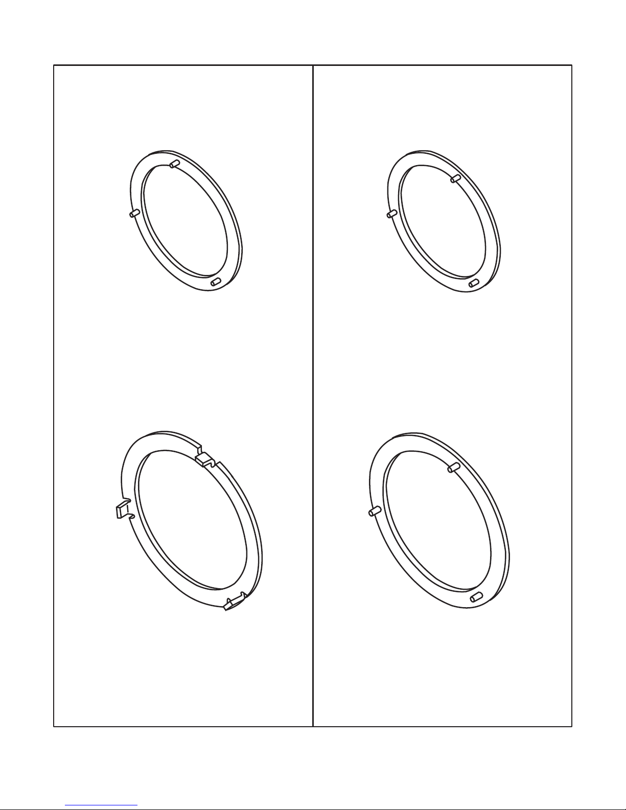
Beginning on October 13, 1995, introduced as a running change for 1996 models, the AX4S
transaxles were built with new design Number 1 and Number 3 thrust washers (See Figure 84).
To improve the assembly process.
NUMBER 1 THRUST WASHER - New design washer has symetrically located tabs for ease af
assembly, as opposed to the previous design with non-symetrically located tabs. Refer to Figure
84 for illustrations of both designs.
NUMBER 3 THRUST WASHER - New design washer is Black plastic with 3 symetrically
located tabs, as opposed to previous design bronze washer with tangs on the outside diameter.
Refer to Figure 84 for illustrations of both designs.
CHAIN COVER - New design will accept either the previous bronze No. 3 thrust washer with the
tangs on outside diameter, or the new design Black plastic No. 3 thrust washer with the 3
symetrically located tabs, as shown in Figure 86.
The previous design Chain Cover will accept only the bronze No. 3 thrust washer with the tangs on
the outside diameter, as shown in Figure 85.
The new design Chain Cover will accept only the new design No. 1 thrust washer with 3
symetrically located tabs, as shown in Figure 86.
The previous design Chain Cover will accept only the previous design No. 1 thrust washer with 3
non-symetrically located tabs, as shown in Figure 85.
If replacement of the number 1 and/or the number 3 thrust washer becomes necessary, inspect the
chain cover in the thrust washer tab areas to determine the correct thrust washers required. Refer to
Figures 85 and 86.
Number 1 Thrust Washer (Before 10/13/95) .....................................................
Number 3 Thrust Washer (Before 10/13/95) .....................................................
Number 1 Thrust Washer (On or After 10/13/95) ..............................................
Number 3 Thrust Washer (On or After 10/13/95) ..............................................
E6DZ-7G099-A
E6DZ-7G096-A
F5DZ-7G099-A
F5DZ-7G096-A
Page 97
Copyright © 2002 ATSG
AUTOMATIC TRANSMISSION SERVICE GROUP
Technical Service Information
97
Figure 84
PREVIOUS DESIGN NEW DESIGN
NUMBER 1 THRUST WASHER
WITH NON-SYMETRICALLY LOCATED TABS
PART NUMBER E6DZ-7G099-A
NUMBER 1 THRUST WASHER
WITH SYMETRICALLY LOCATED TABS
PART NUMBER F5DZ-7G099-A
NUMBER 3 PLASTIC THRUST WASHER
WITH SYMETRICALLY LOCATED TABS
PART NUMBER F5DZ-7G096-A
NUMBER 3 BRONZE THRUST WASHER
WITH TANGS ON OUTSIDE DIAMETER
PART NUMBER E6DZ-7G096-A
Page 98
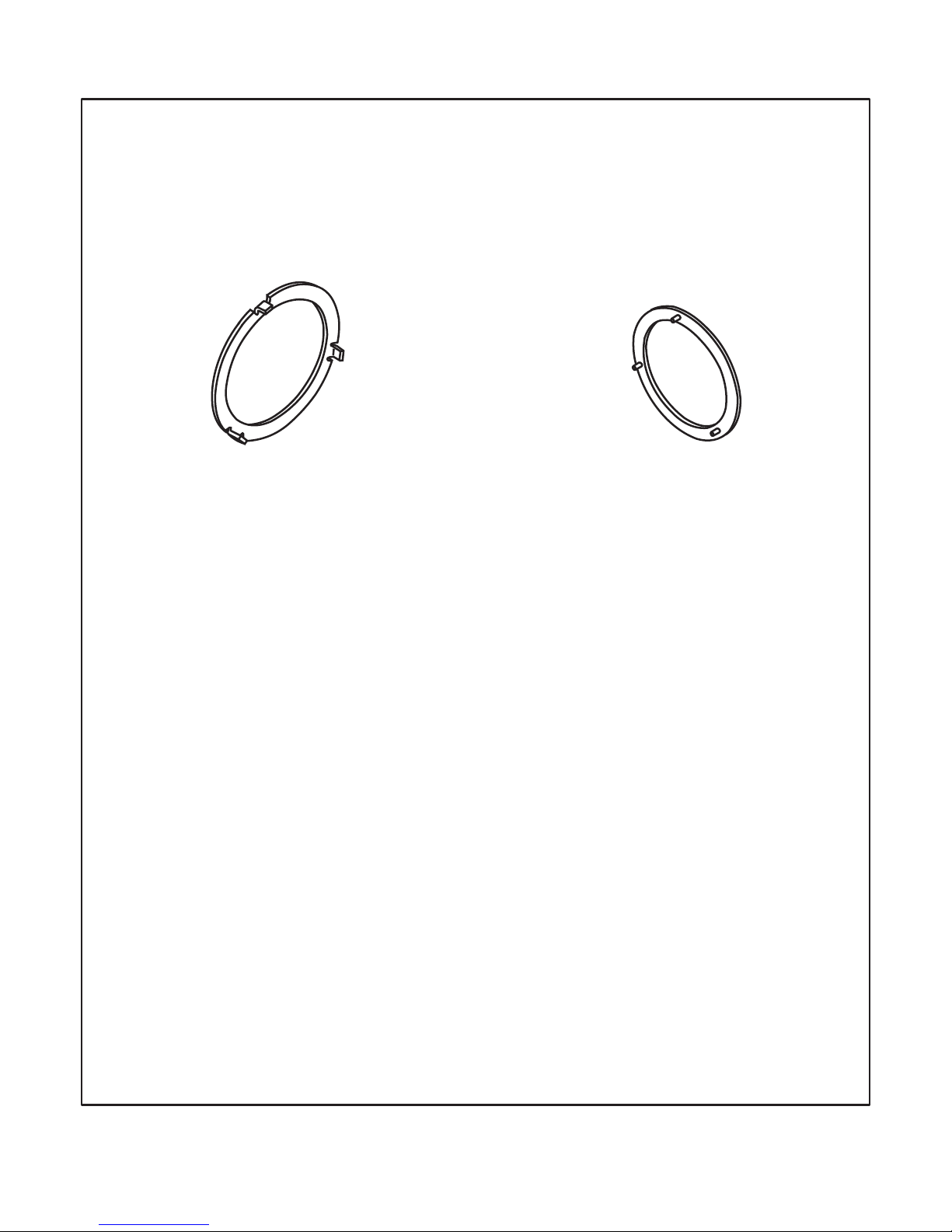
NO. 1 THRUST WASHER LOCATION
WITH NON-SYMETRICALLY LOCATED
HOLES FOR THRUST WASHER
NO. 3 THRUST WASHER
LOCATION WITH CAST
GROOVES FOR THRUST
WASHER RETENTION
CHAIN COVER AND THRUST WASHERS
PRIOR TO OCTOBER 13, 1995
REQUIRES THE BRONZE NO. 3
THRUST WASHER WITH TANGS ON
THE OUTSIDE DIAMETER
PART NUMBER E6DZ-7G096-A
REQUIRES THE PLASTIC NO. 1
THRUST WASHER WITH TABS THAT
ARE NON-SYMETRICALLY LOCATED
PART NUMBER E6DZ-7G099-A
NUMBER 3
THRUST WASHER
NUMBER 1
THRUST WASHER
98
Copyright © 2002 ATSG
AUTOMATIC TRANSMISSION SERVICE GROUP
Technical Service Information
Figure 85
Page 99
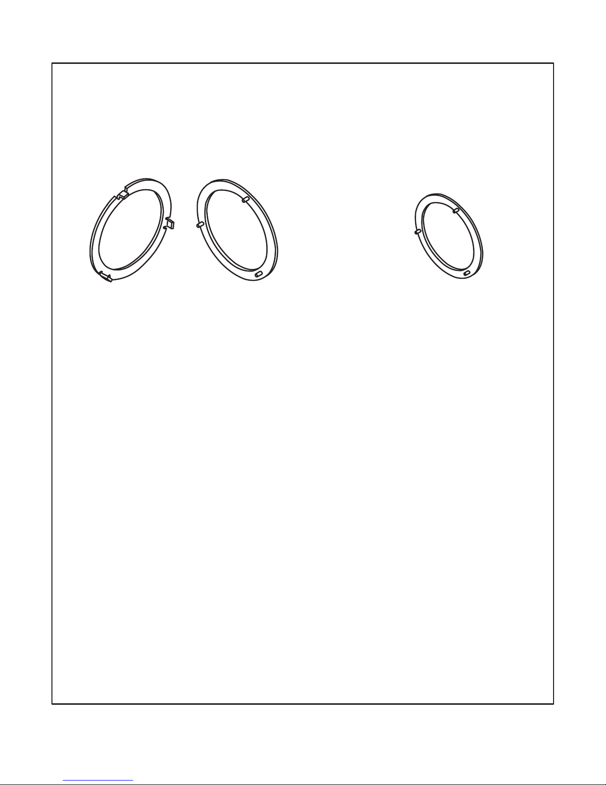
NO. 1 THRUST WASHER LOCATION
WITH SYMETRICALLY LOCATED
HOLES FOR THRUST WASHER
NO. 3 THRUST WASHER LOCATION
WITH SYMETRICALLY LOCATED
HOLES AND CAST GROOVES
FOR THRUST WASHER RETENTION
CHAIN COVER AND THRUST WASHERS
OCTOBER 13, 1995 AND BEYOND
CAN USE EITHER OF THE
PART NUMBERS LISTED ABOVE
(BLACK PLASTIC)
F5DZ-7G096-A
(BRONZE)
E6DZ-7G096-A
REQUIRES THE PLASTIC NO. 1
THRUST WASHER WITH TABS THAT
ARE SYMETRICALLY LOCATED
PART NUMBER F5DZ-7G099-A
NUMBER 3
THRUST WASHER
NUMBER 1
THRUST WASHER
99
Figure 86
Copyright © 2002 ATSG
AUTOMATIC TRANSMISSION SERVICE GROUP
Technical Service Information
Page 100
100
Copyright © 2002 ATSG
Technical Service Information
AUTOMATIC TRANSMISSION SERVICE GROUP
FORD AXOD-E (1991-1992 ONLY)
ELECTRICAL DIAGNOSIS (UPDATED)
EPC SOLENOID:
TRANSAXLE OIL TEMPERATURE SENSOR (TOT):
MODULATED LOCK-UP SOLENOID (MLUS):
LOCK-UP SOLENOID (LUS):
Wires for the Electronic Pressure Control solenoid are fed through pins 1 and 6 of the "Black/Gray" case
connector, located on top of the transaxle (See Figure 88). Ohmmeter across terminals 1 and 6 should read
2.5-6.5 Ohms resistance.
Wires for the Modulated Lock-Up Solenoid (MLUS) are fed through pins 4 and 5 of the "Gray" case
connector, located on top of the transaxle (See Figure 88). Ohmmeter across terminals 4 and 5 should read
0.75-2.0 Ohms resistance if you have MLUS. The Modulated Lock-Up Solenoid (MLUS) is found on the
Lincoln Only for the 1991 model year. Taurus/Sable for 1991 are the regular Lock-Up Solenoid (LUS) that is
described below. All models for 1992 model year are MLUS.
Wires for the Lock-Up Solenoid (LUS) are fed through pins 4 and 5 of the "Black" case connector, located on
top of the transaxle (See Figure 88). Ohmmeter across terminals 4 and 5 should read 16-40 Ohms resistance
if you have LUS. The Lock-Up Solenoid (LUS) is found on the Taurus/Sable Only for the 1991 model year.
Lincoln for 1991 is the Modulated Lock-Up Solenoid (MLUS) that is described above. All models for 1992
model year are MLUS.
CAUTION! POPPED A COMPUTER LATELY? CAUTION!
CAUTION! CAUTION! CAUTION! CAUTION! CAUTION!
TOT SENSOR (OHMS)
100k - 37k
37k - 16k
16k - 5k
5k - 2.7k
2.7k - 1.5k
1.5k - 0.8k
0.8k - 0.5k
°C °F
59-104
105-158
159-194
195-230
231-266
21-40
41-70
71-90
91-110
111-130
0-20 32-58
267-302131-150
Wires for the Transaxle Oil Temperature (TOT) sensor are fed through pins 2 and 3 of the "Black/Gray" case
connector, located on top of the transaxle (See Figure 88). Ohmmeter across terminals 2 and 3 should read the
approximate resistance listed in the chart below. Resistance should decrease if transaxle is heated, and
should increase if transaxle is allowed to cool. Oil pan that is warm to the touch is about 105°F-158°F.
 Loading...