

Page 1

Advanced Telemetry Systems
R4500C
(Models: R4500CD or R4500CLD)
Receiver/Datalogger, 12 table version
for use with ATS Coded Transmitters
User Manual
Page 2

Introduction:
The R4500C is a receiver - data logger combination with built in GPS. (An optional GPS antenna is required to use
the GPS feature)
Operationally, the R4500C works by acting as a filter to select a very narrow window in the frequency spectrum.
The position of this filter in the frequency spectrum is determined by the frequency selection (tuning). The receiver
rejects signals and noise outside the filtered window, and passes signals and noise within the window. Additionally,
the receiver translates the signal to a frequency within hearing range that can be heard from the speaker.
The R4500C can store 98304 Stationary data blocks, or 49152 Aerial data blocks or data blocks recorded in the
Manual mode. For Aerial Data, and data recorded in the Manual mode, an extra data block is needed for GPS
information. The data is stored to memory using a looping format. If the data set is maxed out, the newest data will
overwrite the oldest data block. Data blocks consist of the time stamp, frequency, transmitter data, and GPS
location if GPS is used.
The Receiver uses DSP (Digital Signal Processing) technology to achieve better sensitivity, and to help filter out
noise. The DSP digitally samples the audio signal from the R4500C. When the signal has been digitized, the DSP
processor uses internal mathematical calculations to identify signals.
The C suffix indicates the software in this receiver is programmed to detect ATS’s 100 code coded transmitters.
Class B Device Statement: (Section 15.105 (b) of the FCC Rules)
“Note: This equipment has been tested and found to comply with the limits for a Class B digital
device, pursuant to part 15 of the FCC Rules. These limits are designed to provide reasonable
protection against harmful interference in a residential installation. This equipment generates, uses,
and can radiate radio frequency energy and, if not installed and used in accordance with the
instructions may cause harmful interference to radio communications. However, there is no
guarantee that interference will not occur in a particular installation. If this equipment does cause
harmful interference to radio or television reception, which can be determined by turning the
equipment off and on, the user is encouraged to try to correct the interference by one or more of
the following measures:
- Reorient or relocate the receiving antenna.
- Increase the separation between the equipment and receiver.
o Connect the equipment into an outlet on a circuit different from that to which the receiver is
connected.
o Consult the dealer or an experienced radio/TV technician for help.”
Advanced Telemetry Systems, Inc. R4500C Reference User Manual R10-12-A
2
Page 3

Contents
Getting Started page 7
Receiver Controls: page 8
Navigation of the Cursor: page 9
1.0 FREQ -Frequency Entry Mode page 10
2.0 Setup Menu page 11
2.1 Clock page 11
2.2 Defaults page 12
2.2.1 Aerial Defaults page 12
2.2.2 Stationary Defaults page 13
2.3 Stat Hold (Stationary Hold) page 16
2.4 Channel Delay page 16
2.5 Ext Data page 17
2.5.1 RDP – Remote Data Platform page 17
2.5.2 Goes – Geostationary Operational Environmental Satellites page 18
2.6 Tx Type
3.0 Main Menu page 19
3.1 Manual Mode page 19
3.2 Aerial Mode page 20
3.3 STATIONARY MODE page 23
3.3.1 The Stationary Logging Flowchart page 26
3.4 PC MODE page 27
3.5 CLONE page 27
4.0 SCR – Turning the Screen Backlight On and Off page 28
5.0 TEST – View of the “Battery” Voltage page 28
6.0 MEM – View of the “Memory Menu” page 28
6.1 Memory Remaining page 29
Advanced Telemetry Systems, Inc. R4500C Reference User Manual R10-12-A
3
Page 4

6.2 View Data page 30
6.3 Delete Data page 30
7.0 GPS – Viewing / Activating GPS Data page 31
8.0 ADDFR – Adding a Frequency to the Scan Table (Used only in Aerial Mode) page 31
9.0 DELFR – Deleting Frequencies (Used only in Aerial Mode) page 32
10.0 MERGE – Merging Frequency Tables (Used in Stationary and Aerial Modes) page 32
11.0 RECORD – Recording Data (Used only in Aerial and Manual Modes) page 32
12.0 PC – Downloading Data page 32
12.1 Establish communication between the R4500C and the Computer page 32
12.2 Com Port (Settings Menu) page 33
12.3 ATSWinRec page 34
12.3.1 First Time Start Up page 34
12.3.2 Offloading Data page 35
12.3.2 View / Edit Default Configuration page 37
12.3.3 View / Edit Frequency Tables page 38
12.3.4 Delete Data page 39
12.3.5 EXIT page 39
13.0 Setting Aerial Scan Rate page 40
14.0 Setting Stationary Time Out page 40
15.0 Setting Stationary Scan Time page 40
16.0 Offloaded Data Format page 41
17.0 Charging the Batteries page 43
18.0 EXT – External Data Output page 44
18.1 Data Format and Translation page 45
18.1.1 BINARY DATA page 45
18.1.2 GOES Translated Output Format page 46
APPENDIX I – JULIAN DATE CALANDARS page 48,49
Advanced Telemetry Systems, Inc. R4500C Reference User Manual R10-12-A
4
Page 5

Intentionally Left Blank
Advanced Telemetry Systems, Inc. R4500C Reference User Manual R10-12-A
5
Page 6

Advanced Telemetry Systems, Inc. R4500C Reference User Manual R10-12-A
6
Page 7

Intentionally Left Blank
Advanced Telemetry Systems, Inc. R4500C Reference User Manual R10-12-A
7
Page 8
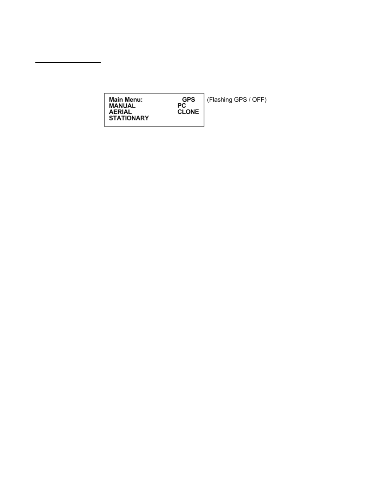
Getting Started:
When you first turn on the power, the receiver will display Advanced Telemetry Systems, the receiver model and
the version number of the receiver software. The display will then proceed to the Main Menu:
Main Menu Items:
GPS indicator: The status of the GPS is displayed in the upper right corner of the screen. The messages indicate
the following:
GPS (non flashing) – The GPS is on, and there is a valid GPS fix.
GPS / OFF – The GPS is turned OFF.
NO / FIX – The GPS is attempting to acquire a valid GPS fix.
GPS / ERR – The GPS has not been able to get a valid GPS fix within 5 minutes.
NO / GPS – The GPS has not been able to get a valid GPS fix after 15 minutes.
If a valid GPS fix is found during NO /FIX, GPS / ERR, or NO / GPS the indicator will change to a non flashing GPS
indicator.
MANUAL: This mode is used to detect transmitters on an individual frequency. Frequency scanning is not available
in this mode. The manual mode does not use pattern matching. The actual pulse rate between any two pulses will
be displayed. Without any pattern matching, the manual mode is helpful to identify a transmitter pulse rate if it is
not known. To save a target in the manual mode, Record would need to be activated. When Record is activated,
GPS locations are also recorded along with the transmitter data if GPS is activated. An optional GPS antenna is
required to use the GPS feature.
AERIAL: Designed for tag location using aircraft. While scanning a table, no information will be recorded unless
Hold is activated. The Hold button is used to toggle between scanning the frequency table, and to hold the
scanning of the frequency table. When Hold is activated, the scanning of the frequency table stops and is held for
the frequency shown in the screen. In Hold, all available information will be continually stored. Tag ID, frequency,
signal strength and time are stored to memory when the operator exits Hold or activates Record. In Hold, Record
needs to be activated when no ID is detected but a Tag can be heard. Aircraft location is also recorded if GPS is
activated. An optional GPS antenna is required to use the GPS feature.
STATIONARY: This mode is used to monitor transmitters passing a site or presence/absence of transmitters. The
time, frequency, signal strength, transmitter ID, and the number of valid transmitter detections per store period are
stored. Scanning is enabled, GPS is disabled.
PC: Used to off load data, send/receive frequency tables and to send/receive receiver programming parameters.
The supplied ATSWinRec software and serial cable must be used with this opti on.
CLONE: Using the optional blue cable, frequency tables and default settings may be cloned from one receiver to
another receiver.
Advanced Telemetry Systems, Inc. R4500C Reference User Manual R10-12-A
8
Page 9

Receiver Controls:
Receiver controls are shown in the figure below. Most are self explanatory. The RF Gain control is normally set to
full clockwise for maximum sensitivity. RF Gain may be reduced for close in searching or while direction finding.
The Audio control should be set for a comfortable level. Its setting does not affect detection sensitivity. Any
monaural headset with a 0.25 inch jack may be used. Most users prefer headsets with muffs to reduce external
noise from wind or aircraft. Inserting the headset jack disables the internal speaker.
The AUX connector is used to interface antenna switches or other controlled devices.
The SIG LED will light for every valid pulse detected. See specifications for valid pulse detections.
Advanced Telemetry Systems, Inc. R4500C Reference User Manual R10-12-A
9
Page 10

Most input and control of the receiver is done through the keypad. The keypad is shown below:
Navigation of the Cursor:
At startup in the Main Menu, the cursor will be positioned on the MANUAL menu item.
To maneuver through the menu items, use the
Both keys will move the cursor. One key moves the cursor in a forward direction
reverse direction. Once the cursor is on the desired menu item, pressing “ENTER” will activate that item.
To access the upper functions on the keypad, first press the “SHIFT” key followed by the desired upper function key
sequentially.
Note: The “SHIFT” key will not be activated if pressed simultaneously with another key.
To stop a scan (Aerial or Stationary), stop a setup sequence, or to return the previous menu, press the “ESC” key.
Pressing the wrong key or entering invalid data will produce the response:
NOT an Option
or
Out of Range
Upper Keypad Functions:
To access the upper keypad functions, first press ”SHIFT” and then press the “upper function” key sequentially.
MENU – Enters the Main Menu
or the keys to move the cursor to the desired menu item.
, and the other in a
Advanced Telemetry Systems, Inc. R4500C Reference User Manual R10-12-A
10
Page 11
SETUP – Enters the Setup Menu
FREQ – Enters the Frequency Menu
SCR – Toggles the display backlight on and off
TEST – Test internal Battery Voltage Level or External Power Supply Voltage Level
MEM – Enters the Memory Menu
GPS – Enters the GPS Menu
MERGE – Merges frequency tables for Aerial or Stationary Scanning
ADDFR – Adds a frequency while Aerial Scanning
DELFR – Deletes a frequency while Aerial Scanning
RECORD – Used to manually record information
F1, F2, F3, F4 – Currently not in use
1.0 FREQ - Frequency Entry Mode
Stationary Mode and Aerial Mode will not function if there are no frequencies in the table selected to scan. The
frequencies should be entered into the frequency table or tables first.
The frequencies entered in the R4500C are 6 digit numbers. For frequencies below 100 MHz, the frequencies are
entered as 5 digit numbers. For example, a frequency of 151.183 MHz will be entered as 151183. A frequency of
48.655 MHz will be entered as 48655.
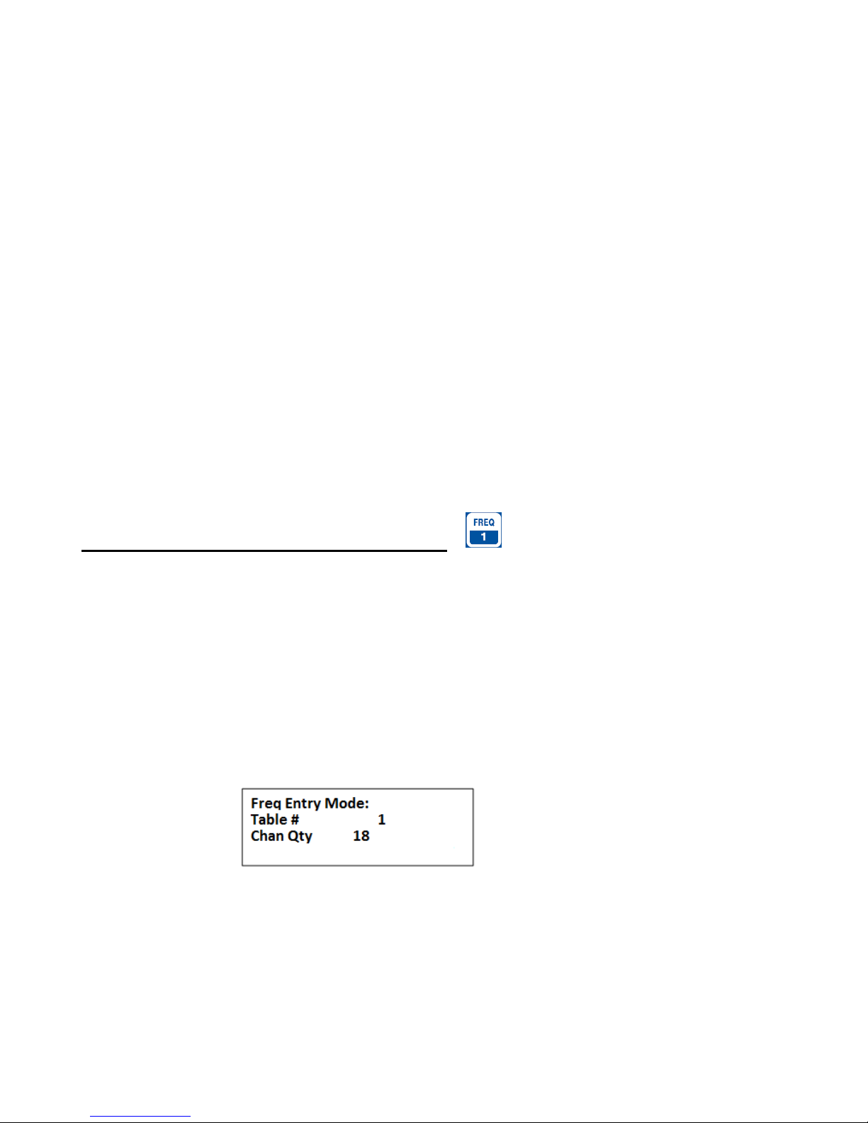
From the Main Menu screen, press the “SHIFT” key followed by pressing the “FREQ” key sequentially. To change
the numeric value, use the numeric digits on the keypad. For the R4500C to accept a value, press “ENTER”.
Screen 1
Table # : Selects the frequency table that you will be storing your transmitters’ frequencies. There
are twelve tables available. Table 1, 2, 3 ….. or 12.
Chan Qty : The number of frequency entries you will be using for the transmitters in this table. Note
the first channel is Channel (00). There are 50 channels available for each frequency table.
After entering the Chan Qty, the screen will change to entering the frequencies.
Advanced Telemetry Systems, Inc. R4500C Reference User Manual R10-12-A
11
Page 12

Screen 2
(The default frequency will be the lowest frequency of the receiver)
FR 1 indicates frequency table 1.
(00) represents the first frequency in the list. The next frequency will be FR 1(01), and so on.
The cursor defaults to the 1 MHz position. Use the
changing. When a number is entered in one location, the cursor will move to the right by one. Pressing “ENTER”
will store the frequency, and move to the next frequency position in the table. When all the frequencies are
entered, the screen will jump back to the start of the Frequency Entry Menu.
If you have overlapping frequencies (i.e. 148.000-151.999) move the cursor to the 10 MHz position and then enter
the desired numeric value.
You may use the CHAN up
keys can be used to make corrections or change an individual channel frequen cy.
and CHAN down keys at any time to scroll through the channels. These
or the keys to move the cursor to the digit that needs
2.0 SETUP Menu
The Setup Menu is used to set the clock, select transmitter type, default settings and delay times for the screen,
stationary hold, the channel delay and set the external data transfer settings. Setting the defaults first will make
starting Aerial or Stationary scans much easier and also re duce potential for errors.
To get into the “Setup Menu”, press the “SHIFT” key followed by pressing the “SETUP” key sequentially.
Again, to maneuver through the menu items, use the
This is the view of the “Setup Menu”
To return to the Main Menu from the Setup Menu, press “ESC”.
2.1 Clock
Advanced Telemetry Systems, Inc. R4500C Reference User Manual R10-12-A
or the keys.
12
Page 13
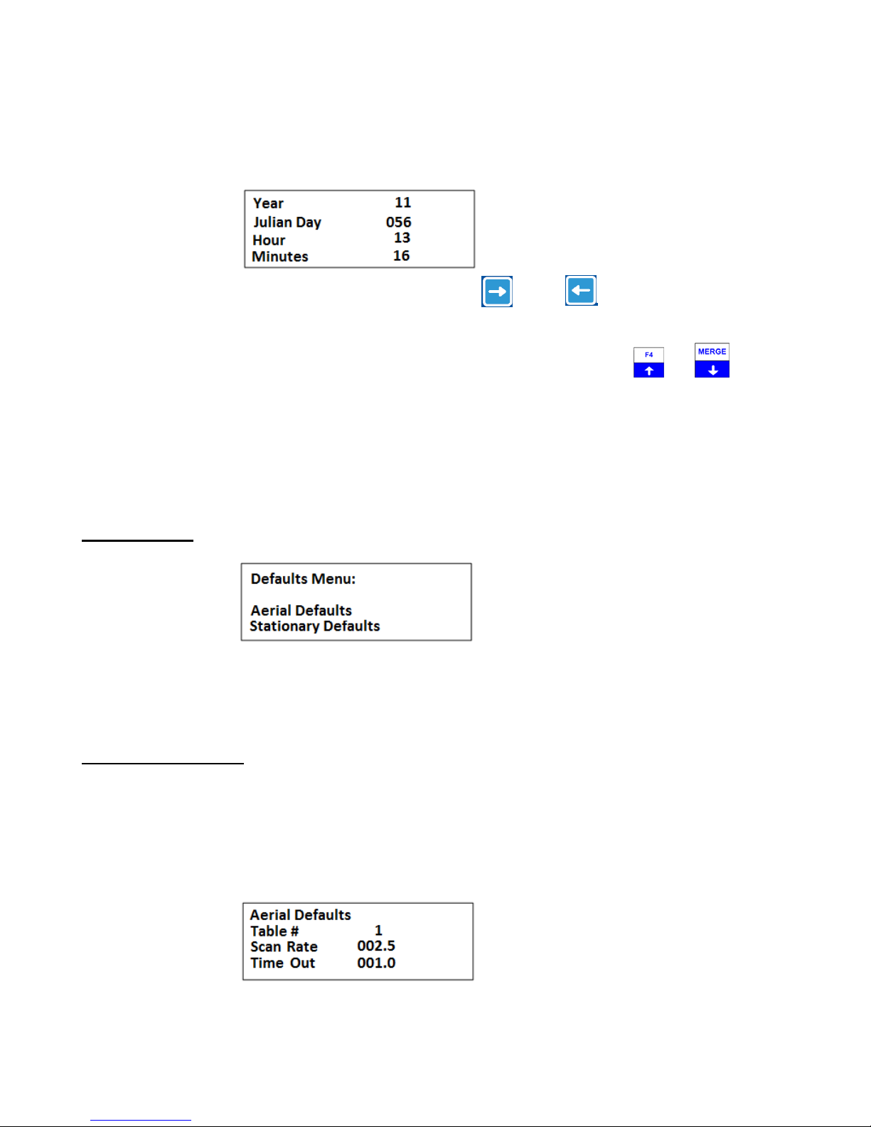
To access the clock, position the cursor on Clock and press “ENTER”.
Here is an example of the Clock Menu:
You can press “ENTER” to go through each setting, or use the
backwards to a specific setting.
To change the numeric value, use the numeric digits on the keypad, or you can use the
increment the numeric value, up or down. For the R4500C to accept a value, press “ENTER”. After the Minutes
have been entered, the menu will return to the “Setup Menu”. If no changes are needed in the Clock Menu,
pressing “ESC” will return you to the “Setup Menu”. If a numeric number has been changed and “ENTER” has not
been pressed, pressing “ESC” will return the value to its original value.
and the keys to move forward or
and keys to
2.2 Defaults
This selection allows you to set Aerial Defaults or Stationary Defaults. Move the cursor to select either Aerial or
Stationary Defaults and press “ENTER”.
2.2.1 Aerial Defaults
Move the cursor to the Aerial Defaults item and press “ENTER”. This menu option sets the default options for
aerial tracking, setting the defaults in this option helps reduce unwanted changes or mistakes in having to set the
parameters during the tracking survey.
Screen 1
Advanced Telemetry Systems, Inc. R4500C Reference User Manual R10-12-A
13
Page 14

Table #: Selects the frequency table used for scanning. Twelve tables are available.
Scan Rate: Sets the amount of time the R4500C will stop on each frequency while attempting
Time Out: The amount of time the receiver will stay on a Frequency while attempting to
Screen 2
Multiple tables are used to optimize Aerial surveys in multiple locations.
to detect tags. The number after the decimal point may be a 0 or a 5 to allow half
second increments.
detect a tag. If no tag is detected in the Time Out period, the receiver will advance
to the next frequency in its frequency table. This feature allows faster scanning by
truncating the scan time if no tag is detected in the Time Out period. The user
defines the parameter (e.g. 003 – 300 seconds). Refer to section 14.0 for
information on setting the Time Out value.
GPS: Sets whether the GPS receiver is on or off when an Aerial Scan starts. An optional
GPS antenna must be connected to the R4500C for this option to work.
2.2.2 Stationary Defaults
Move the cursor to the Stationary Defaults item and press “ENTER”. There will be a number of different screens
to go through when entering the stationary defaults, depending on your screen selections. Pressing “ESC” will bring
you back to the previous screen.
Screen 1
Time Out: The amount of time the receiver will stay on a Frequency while attempting to
detect a tag. If no tag is detected in the Time Out period, the receiver will advance
to the next frequency in its frequency table. This feature allows faster scanning by
truncating the scan time if no tag is detected in the Time Out period. The user
defines the parameter (e.g. 003 – 300 seconds). Refer to section 14.0 for
information on setting the Time Out value.
Scan Time: The amount of time to hold on a frequency and attempt to detect tags. The Scan
time will override the Time Out time, if a pulse has been detected during the Time
Advanced Telemetry Systems, Inc. R4500C Reference User Manual R10-12-A
14
Page 15
Out period. The Scan Time is set to whatever you need this set at (e.g. 003 – 300)
seconds. Refer to section 15.0 for information on setting the Scan Time value.
Store Rate: This defines how often a tag’s detection will be stored for each antenna. For
example if the Store Rate is set to 10 minutes and a scan time of 15 seconds, its
presence will only be recorded once during that 10 minute period. The data stored
will include the time stamp of the strongest signal strength measured in one 15
second scan time during the 10 minute scan period. Stored with it will be all
detected ID’s for that frequency, and the total count of detections for each ID
during the 10 minute store period.
Pressing “ENTER” while on the Store Rate setting will advance to the next screen.
Screen 2
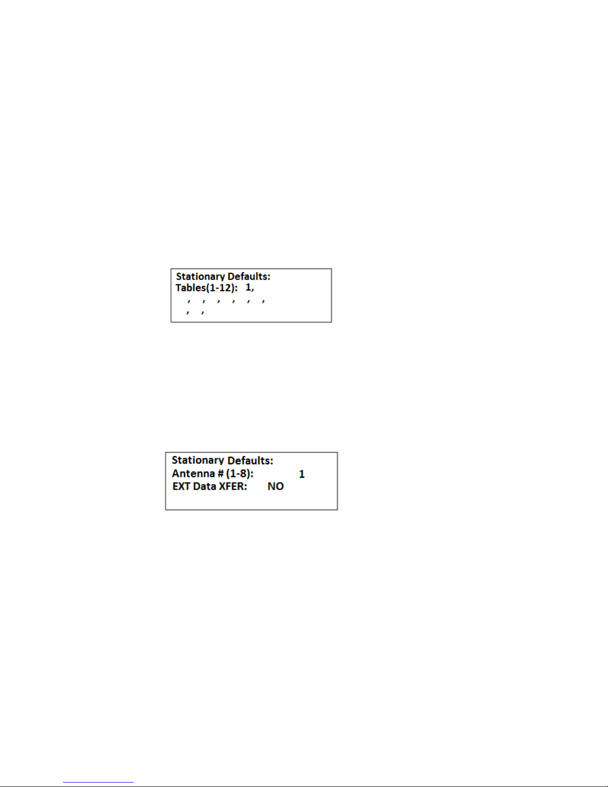
Tables : The frequency tables you want to scan. There are twelve tables available.
Pressing “ENTER” while on the Store Rate setting will advance to the next screen.
Screen 3
Antenna # : The number of antennas the receiver will sample. This feature requires an
external antenna switchbox connected to the AUX port of the R4500C. If using a
2-way switchbox, this would be set to 2.
EXT Data XFER: This setting is set to YES when transferring recorded data every hour to another
device. This can be used for retrieving your data remotely. Two example devices
are RDP (Remote Data Platform) and GOES (Geostationary Operational
Environmental Satellites). The GOES satellite operation requires an account with
NESDIS (National Environmental Satellite, Data and Information Service). Contact
ATS for more information regarding GOES and RDPs.
Pressing “ENTER” while on the EXT Data XFER setting will advance to the next screen.
Advanced Telemetry Systems, Inc. R4500C Reference User Manual R10-12-A
15
Page 16

Screen 4
To activate the Reference tag feature, use the
or the key. These two keys are used to toggle between
the two choices.
If you entered YES for the reference tag, you will be prompted to enter the reference tag frequency, and the store
rate of the reference tag.
Screen 5
Reference Freq: This is the frequency of a radio tag set up within range of your station used as a
check on the system. Since you will not need the same quantity of data you can
set up a longer store period to use up less memory. Instead of the strongest signal
strength being stored within the storage period, it will be the time of the first valid
ID detection.
Note: There is a limit on the number of reference transmitter points that can be
collected during each storage period. The maximum number is 16 (I.E. The
number of collocated codes on the reference frequency times one plus the number
of antennas should not be greater than 16).
An example dataset is shown below:
Date, Ant, Fr, Sig, Code, NumDet, NumMort
7/17/2009 12:47, 0, 150983, 105, 9, 18, 17
7/17/2009 12:47, 0, 150983, 133, 18, 36, 36
7/17/2009 12:47, 0, 150983, 135, 42, 35, 35
7/17/2009 12:47, 0, 150983, 119, 15, 15, 15
7/17/2009 12:47, 0, 150983, 122, 86, 40, 40
7/17/2009 12:47, 0, 150983, 121, 6, 42, 42
7/17/2009 12:47, 0, 150983, 121, 78, 46, 46
7/17/2009 12:47, 0, 150983, 135, 71, 34, 34
7/17/2009 12:47, 0, 150983, 141, 79, 48, 48
7/17/2009 12:47, 0, 150983, 135, 12, 12, 12
7/17/2009 12:47, 1, 150983, 106, 9, 25, 25
7/17/2009 12:47, 1, 150983, 126, 86, 31, 31
7/17/2009 12:47, 1, 150983, 119, 15, 29, 29
7/17/2009 12:47, 1, 150983, 120, 6, 38, 38
7/17/2009 12:47, 1, 150983, 132, 18, 33, 33
7/17/2009 12:47, 1, 150983, 136, 42, 30, 30
Advanced Telemetry Systems, Inc. R4500C Reference User Manual R10-12-A
16
Page 17

For this example there were 2 antennas selected and 10 reference transmitters.
The reference transmitter codes were 6, 9, 15, 18, 42, 71, 78, 79, 86. There should
have been 30 data points if all the transmitters had been picked up for each
antenna during this store period. Instead the data shows detections for all the
reference transmitters shown for antenna 0, only 6 shown for antenna 1 and none
shown for antenna 2. The maximum number of reference transmitters that can be
used when switching between two antennas is five
Store Rate: This defines how frequently the data from the reference transmitter will be stored.
A count of the number of detected tag ID’s will be stored for the entire store rate.
Note: The data are not stored until the storage period has expired. For example with storage period set up for once
an hour the time the first data are collected might be at 6:00 am. Although the data recorded will reflect 6:00 they
will not be committed to memory until 7:00 am. This means when the data are offloaded you may have the data for
the actual transmitters appearing before the reference tag. This is true even if the animal data were collected at
6:30 am and the reference data were collected at 6:00 am.
2.3 Stat Hold (Stationary Hold)
(This time setting is only used only for a Stationary Scan and is not used for Hold during Aerial Scanning)
Stat Hold is abbreviated for Stationary Hold time (Range = 00005 to 65535 seconds). The Stationary Hold time is
the number of seconds the “HOLD” feature can remain in the Hold position when activated during a Stationa ry
Scan. Pressing “HOLD” before the Stat Hold time has expired will resume the stationary scan. The “HOLD”
feature may be used to monitor a transmitter for a period of time longer than the Scan Time during a Stationary
Scan. If the user does not exit the “HOLD” mode, the R4500C will automatically resume scanning after the number
of seconds has been reached. This is a safety feature added to prevent the possibility of a stationary scan
remaining in Hold at a remote location.
Pressing “ENTER” or “ESC” from the “Stat Hold” menu will bring you back to the “Setup Menu”.
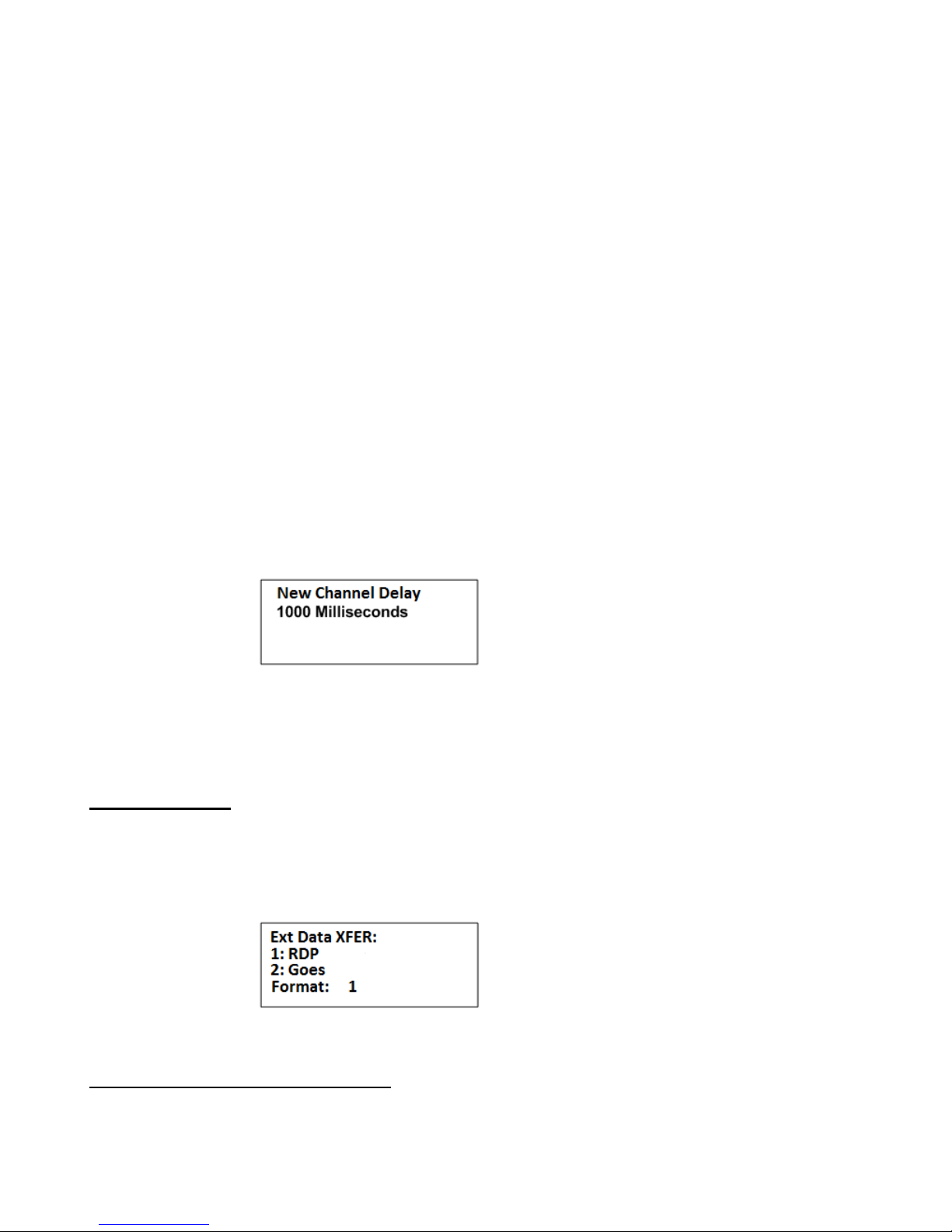
2.4 Channel Delay
During a stationary scan, when switching to a new frequency the “Channel Delay“ will be activated. The available
delay time is 0-5000 milliseconds. The default Channel Delay time is 1000 milliseconds (1 second). The purpose of
the Channel Delay is to filter out unwanted noise pulses when switching frequencies. The R4500 C filters out
unwanted noise pulses during the Channel Delay time by ignoring all pulses detected during the entered time, 0 –
5000 milliseconds. The scan time of each frequency does not start until the Channel Delay time has expired.
This adjust is available for cases where the noise level changes significantly when frequency channels are
changed. The R4500C measures the average background noise level and adjusts the detection level accordingly. If
the background noise level changes dramatically between chann els, more time is needed to adjust to the new
threshold level. When using multiple antennas the system monitors all antennas for the first two seconds (Time Out
setting), if there are no pulses present, the search on all antennas is terminated and any other antennas are
skipped. This saves scan time and allows all channels to be searched more often.
To determine if extra delay is needed, cycle through the frequency table with no transmitters present to determine
if noise pulses cause the receiver to cycle through the multiple antenna sequence. If the receiver scans through all
Advanced Telemetry Systems, Inc. R4500C Reference User Manual R10-12-A
17
Page 18
antennas on several or all frequency channels even with no signal present; you may want to increase the Channel
Delay time. If noise pulses are present, and the multiple antenna scanning sequence does not start, the Channel
Delay time is set correctly.
Setting the Channel Delay time longer gives more time for the R4500C to set a new threshold and optimize
sensitivity while at the same time ignoring noise. Setting it longer than necessary means the additional delay will be
added to every frequency channel scanned also increasing the time for all channels to be scanned. Thus the goal is
to set the delay so most, but not necessarily all noise pulses on every channel are ignored. Occasionally high level
noise will still pass no matter how long the delay is made.
Example of scan times with no transmitters present: Number of antennas used = 2. Time out = 3 seconds. Scan
time = 10 seconds. Number of frequencies used in table scanned = 10.
If the noise level is higher than the noise threshold level the R4500C has set, the noise will produce signal pulses
and the receiver will think transmitters are present and then cycle through the individual antennas. With no
transmitters in the area, but with noise pulses indicating possible presence of transmitters, the time for a scan of the
complete frequency table will be: Scan Time of antenna 0 + Time Out of antenna 1 + Time Out of antenna 2 = 10 +
3 + 3 = 16 seconds. For the10 frequencies in the table, the total scan time will be 160 seconds. (When an individual
antenna is selected, the noise level decreases and there should not be any noise pulses produced)
When using the default Channel Delay of 1000 milliseconds and there are no noise pulses above the threshold nor
are any transmitters present; the time of the frequency table scan will be: Channel Delay time + Time Out of
antenna 0 = 1 + 3 = 4 seconds. For the10 frequencies the total scan time would be 40 seconds. With the Channel
Delay set correctly, scan times can be reduced by allowing time for the R4500C to set the correct noise threshold
level.
Enter a numeric number from 0 to 5000 and press “ENTER”.
Pressing “ENTER” or “ESC” will return the screen back to the “Setup Menu”.
2.5 Ext Data
This optional feature is used when you want to dump data out hourly through a serial port to another device. This
screen is used to select the type of device you want to dump to. For this feature to be activated it will need to have
been selected for in screen 6 of the Stationary Setup.
Enter a 1 or 2 for the type of device and press “ENTER”.
2.5.1 RDP – Remote Data Platform
Advanced Telemetry Systems, Inc. R4500C Reference User Manual R10-12-A
18
Page 19
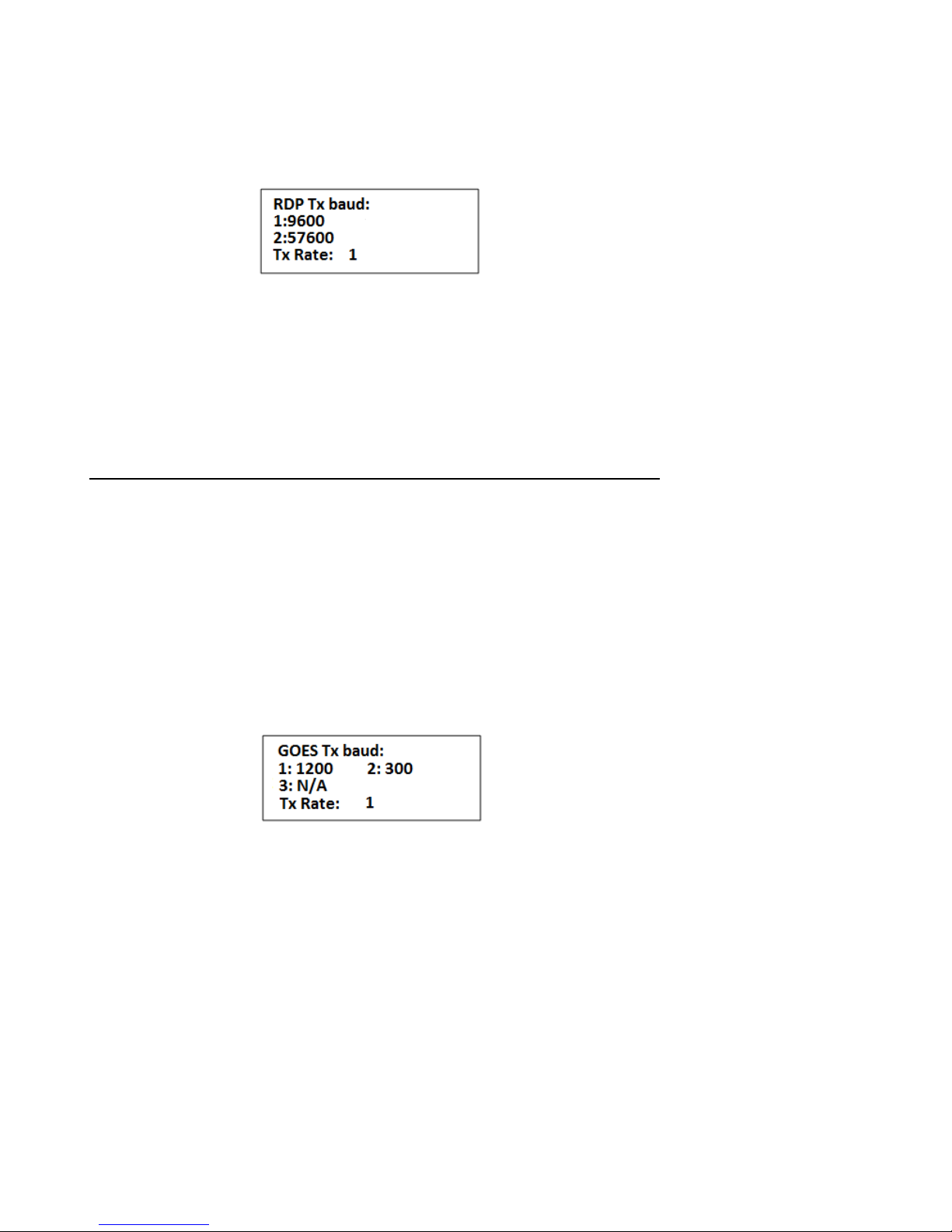
With this setting selected all the data collected during the hour will be dumped out the PC/CLONE serial port as
binary compressed data.
Screen 2
9600 : Sets the se rial communication settings for the R4500C’s data output to
“baud: 9600, no parity, 8 data bits, 1 stop bit”.
57600: Sets the serial commu nication settings for the R4500C’s data output to
“baud: 57600, no parity, 8 data bits, 1 stop bit”.
Enter a 1 or 2 for the desired serial port settings and press “ENTER”. The screen will return to the “Setup Menu”
2.5.2 Goes – Geostationary Operational Environmental Satellites
With this setting selected, limited amounts of data collected during the hour will be dumped out the PC/CLONE and
AUX serial ports as binary compressed data.
The GOES functionality enables the receiver to send data to a geostationary satellite so that the user can retrieve it
later from another location. This system has the advantage of working in remote locations not typically covered by
standard cell phone service providers.
To use GOES you first need an account with NESDIS (National Environmental Satellite, Data and Information
Service). You also need a GOES Transmitter. Both the SAT HDR GOES and TX312 models sold by Campbell
Scientific, Inc are compatible with the data protocol being sent out the AUX serial port. The data coming out the
PC/CLONE port is standard RS232 with settings: “baud: 9600, no parity, 8 data bits, 1 stop bit”.
Screen 2
1200: Informs the R4500C that the GOES satellite will be transmitting data back to Earth
at 1200 baud. This value is assigned by NESDIS (National Environmental Satellite,
Data and Information Service).
300: Informs the R4500C that the GOES satellite will be transmitting data back to Earth
at 300 baud. This value is assigned by NESDIS (National Environmental Satellite,
Data and Information Service).
N/A: Informs the R4500C that it doesn’t need to worry about the GOES transmission
rate. You would select this if you wanted to take advantage of the GOES data
format without actually using the GOES transmitter and setup.
Enter a 3 to finish or a 1 or 2 to continue to the next screen and press “ENTER”.
Advanced Telemetry Systems, Inc. R4500C Reference User Manual R10-12-A
19
Page 20

Screen 3
Enter the value of the transmit window size assigned by NESDIS and press “ENTER”.
Screens 2 and 3 are used to limit the amount of data dumped out the serial port. The data size will be a size that
can be handled by hourly satellite transmissions. Data that doesn’t get sent to the GOES transmitter this hour will
be saved for the next hours dump. If you anticipate having intervals where you collect more data than can be sent
by a satellite transmission, you will need to make sure you have intervals where you collect limited data so the
system can catch up.
2.6 Tx Type
This optional feature allows you to select what type of transmitter type you will be monitoring.
Unless this selection is changed the default will be Coded. To select move the cursor to select either Codedl or
Coded with Data and press “ENTER.
The with data is used when you want to use tags that have a few extra pulses in their code that translate to some
data from some measurement the tag is designed to take such as temperature. The coded pulse strea m is decoded
into a Tx Id, data type and period. The period can be then plugged into an equation such as a quadratic to give the
measurement of interest.
3.0 Main Menu
Advanced Telemetry Systems, Inc. R4500C Reference User Manual R10-12-A
20
Page 21

Move the cursor with the
positioned over your selection press “Enter” to activate it.
or the keys to navigate through the menu items. Once you have the cursor
3.1 MANUAL MODE
With the cursor in the MANUAL position, press “ENTER”.
The GPS is normally OFF for the Manual Mode. If the GPS has been turned on previously from the GPS Screen,
or an Aerial Scan, the GPS will remain on when entering the Manual Mode.
To change the frequency
The cursor defaults to the 1 MHz position. From here you can enter whatever frequency you are looking for.
You may use the
using the keypad. Each time you enter a digit the cursor will move one place to the right. If the cursor is in the 1
kHz position (least significant digit), then it will just remain in that location. Receiver frequency is also updated after
each key is entered.
Pressing “ENTER” will move the cursor to the default location of the 1 MHz position. It does not change the last
entered frequency. You may also use the left and right arrow keys to move the cursor around and change the
frequency by entering a new digit.
The
the same location.
If the enter frequency that is not within the receiver’s range,
“Out of range” error will be displayed.
The Manual mode does not automatically store the data. To store data in the manual mode, pressing “SHIFT” and
and the keys can be used to increment or decrement a numeric value while keeping the cursor in
or the keys to change the cursor position. More likely you will enter tag frequencies
then “RECORD”
The Manual mode will display ID tags on the display as it decodes them. Other than storing data, all the features
described in the Aerial’s Hold mode also work here.
Advanced Telemetry Systems, Inc. R4500C Reference User Manual R10-12-A
will store all data that has been detected and is displayed in the screen.
21
Page 22
The time stamp of all detected tag ID’s will be stored when pressing “RECORD”
the frequency is saved along with the latest time stamp. Note: GPS data will only be stored if an optional antenna
is connected to the receiver, the GPS functionality is turned on and a valid GPS fix has been acquired.
Saving targets will flash on the display
To exit the Manual mode, press the “ESC” key.
. If no ID’s are available, only
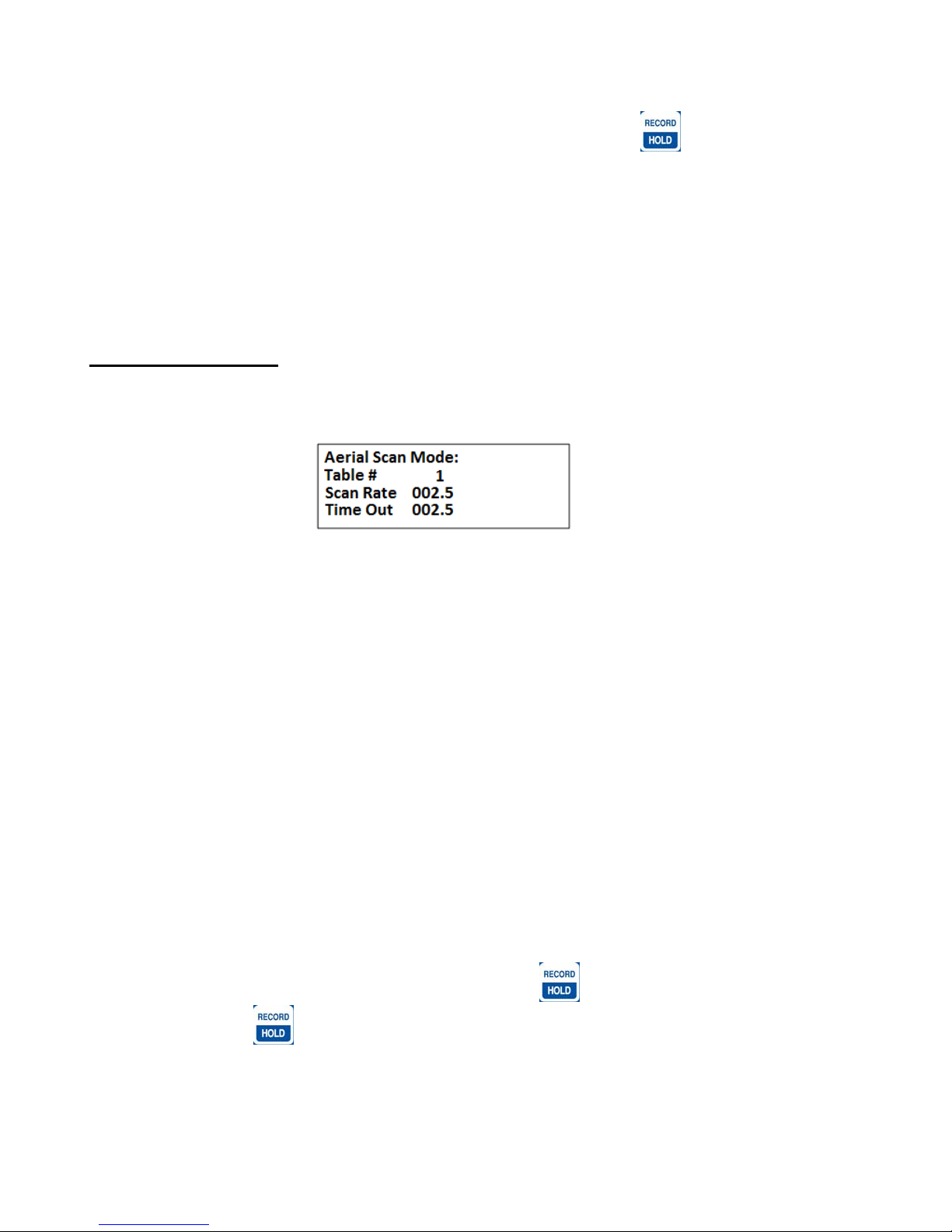
3.2 AERIAL MODE
Move the cursor to the AERIAL item and press “ENTER”.
Screen 1
Table #: Selects the frequency table used for scanning. Twelve tables are available.
Multiple tables are used to optimize Aerial surveys in multiple locations.
Scan Rate: Sets the amount of time the R4500C will stop on each frequency while attempting
to detect tags. The number after the decimal point may be a 0 or a 5 to allow half
second increments. For setting Scan Rate time, see section 13.0.
Time Out: The amount of time the receiver will stay on a Frequency while attempting to
detect a tag. If no tag is detected in the Time Out period, the receiver will advance
to the next frequency in its frequency table. This feature allows faster scanning by
truncating the scan time if no tag is detected in the Time Out period. The user
defines the parameter (e.g. 003 – 300 seconds). Refer to section 14.0 for
information on setting the Time Out value.
If the defaults were set up correctly, just press enter for each item listed, and the cursor will move through each
setting in the Aerial Setup windows. When all settings have been entered, the Aerial scan will start.
The default settings are used to pre - enter the values for each item listed for the Aerial Setup. Pressing “ENTER”
on these values stores them into memory. If there needs to be any changes made to any of the items, pressing
“ENTER” will store the changed value into memory, and that changed value will be used in the Aerial scan.
When an Aerial Scan has started, the R4500C will start scanning the frequencies in the table at the entered scan
rate time. When a tag is heard on a frequency, pressing “HOLD”
frequency until “HOLD”
scanning through the frequencies in the table at the scan rate time.
Advanced Telemetry Systems, Inc. R4500C Reference User Manual R10-12-A
is pressed again. When Hold is pressed the second time, the R4500C will resume
will stop the scan rate and remain on that
22
Page 23

You may use the “CHAN
” and “CHAN ” keys at any time to scroll through the channels. When the
is scanning through the frequencies, pressing the chan up or chan down keys will override the scan rate time, and
advance forward or backwards through the frequency table. While in Hold, pressing the chan up or chan d own
keys will advance forward or backwards through the frequency table and remain in the Hold state, recordi ng any
available information when detected.
While in Hold, the tune up
and the tune down keys can be used to increment or decrement the
frequency.
Example 1:
Example 2:
Hold: Pressing the “HOLD”
key will cause the aerial scanning to stop on the current frequency and
store data continually. When this has occurred the “Hold” text will appear on the screen. Use this
key when you want to store data (i.e. time, frequency, signal strength, tag ID, and GPS location) for
the displayed frequency. Pressing the “HOLD”
key again will cause the R4500C to resume s
canning.
To access functions available to this mode press a “SHIFT” key “VIEW
“MERGE”
, “ADDFR” , “DELFR” , or “RECORD” key.
Advanced Telemetry Systems, Inc. R4500C Reference User Manual R10-12-A
”, “VIEW ” ,
23
Page 24
GPS: This flashing message will indicate the status of the GPS functionality. GPS data will only be stored
if an optional antenna is connected to the receiver, the GPS functionality is turned on and a valid
GPS fix has been acquired.
ID’s: When a transmitter is identified, the ID will appear in the display. The screen has only enough
room to display 6 ID’s. If more than 6 ID’s are detected, there will be a “+” indicator in the bottom
right hand corner of the display. To view the other ID’s use the VIEW
and the VIEW
as scroll keys. Shown in Example 1 is the first page of the detected tag ID list. The most
recently detected ID will appear in the upper left hand corner of the display. Note that the first two
lines of IDs have no “+” indicator on the right hand side. Example 2 shows all three lines with a “+”
indicator. This shows that the list can scroll both up and down. The absence of any IDs in the
bottom row indicates that scrolling down will not show any more detected IDs. A “...............+” on
the display indicates you’ve reached the end of the list’s storage area. All detected IDs will be
stored to memory for downloading to the PC. The ID will be shown on the screen as a three digit
number followed by its mortality indicator and its signal strength reading. The first two digits are
the tag ID. The third digit is a counter that will increment every time the tag ID is identified. This
counter will loop from 0-9. (For example: 127 = ID number 12, and has been detected 7 times.) If a
tag is in mortality mode the ID information will show an ‘M’ where a ‘-‘ would normally appear.
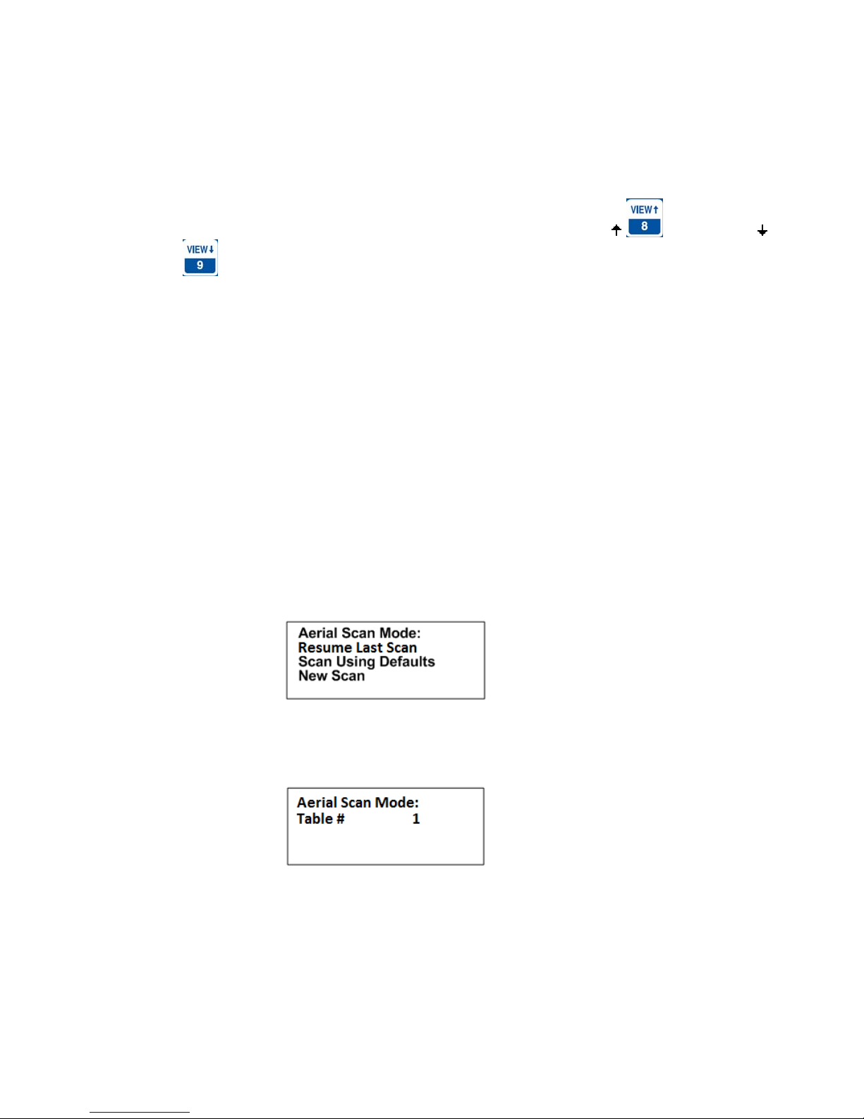
To stop the Aerial Scan, press “ESC”. This will return the screen to the “Main Menu”
If you desire to start the aerial scan after stopping the scan, a new window will appear when entering the “Aerial
Menu”.
Screen 1:
Pressing “ENTER” while the cursor is on Resume Last Scan, the following screen will come up:
Screen 2:
Pressing “ENTER” while the cursor is on the table number will start an aerial scan using all the frequencies
that may have been added or deleted including any merged tables. Specifying a table number then
pressing “ENTER” will perform the same task but first it will clear out the merged tables while maintaining
the added and deleted frequencies from the table specified.
Pressing “ENTER” while the cursor is on Scan Using Defaults, the Aerial Scan will start scanning using the values
entered for the Aerial default settings.
Advanced Telemetry Systems, Inc. R4500C Reference User Manual R10-12-A
24
Page 25
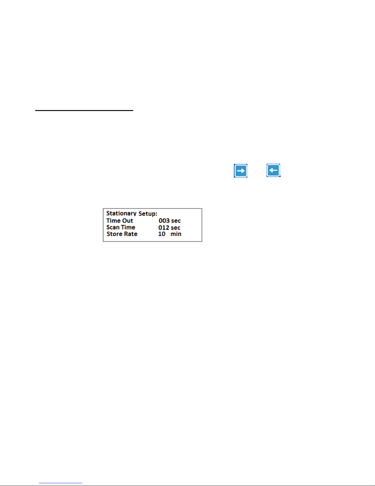
If a new scan is started by starting an Aerial Scan from the “Main Menu”, the changed values will be returned to the
default values if Scan Using Defaults is selected. If any of the scan protocol values need to be changed, you will
need to move the cursor to New Scan and press “ENTER”. The values in the list will show the default values. If
you want the values to be remembered for future scans go back to the “Defaults Menu” and make the changes
there. With the “ATSWinRec” software, there is the option to offload the data showing the scan parameters. When
this option is selected, the values used for the scan will be able to be viewed along with the data.
3.3 STATIONARY MODE
Move the cursor to the STATIONARY item and press “ENTER”. See section 3.3.3 for viewing the stationary
flowchart. The stationary mode has a low battery indicator. The LOW / BAT indicator will flash in the display when
the internal battery voltage is below 11.5V. If external power is connected to the receiver, the internal batteries are
not used, and the low battery indicator will be for the external power supply.
There will be multiple windows to go through. Moving the cursor with the
between screens.
Screen 1
Time Out: The amount of time the receiver will stay on a Frequency while attempting to
detect a tag. If no tag is detected in the Time Out period, the receiver will advance
to the next frequency in its frequency table. This feature allows faster scanning by
truncating the scan time if no tag is detected in the Time Out period. The user
defines the parameter (e.g. 003 – 300 seconds). Refer to section 14.0 for
information on setting the Time Out value.
Scan Time: The amount of time to hold on a frequency and attempt to detect tags. The Scan
time will override the Time Out time, if a pulse has been detected during the Time
Out period. The Scan Time is set to whatever you need this set at (e.g. 003 – 300)
seconds. Refer to section 15.0 for information on setting the Scan Time value.
Store Rate: This defines how often a tag’s detection will be stored for each antenna. For
example if the Store Rate is set to 10 minutes and a scan time of 15 seconds, its
presence will only be recorded once during that 10 minute period. The data stored
will include the time stamp of the strongest signal strength measured in one 15
second scan time during the 10 minute scan period. Stored with it will be all
detected ID’s for that frequency, and the total count of detections for each ID
during the 10 minute store period.
Pressing “ENTER” while on the Store Rate setting will advance to the next screen.
Screen 2
or the will allow movement
Advanced Telemetry Systems, Inc. R4500C Reference User Manual R10-12-A
25
Page 26

Tables : The frequency tables you want to scan. There are twelve tables available. All the
Screen 3
tables listed will be scanned.
Antenna # : The number of antennas the receiver will sample. This feature requires an
external antenna switchbox connected to the AUX port of the R4500C. If using a
2-way switchbox, this would be set to 2.
EXT Data XFER: This setting is set to YES when transferring recorded data every hour to another
device. This can be used for retrieving your data remotely. Two example devices
are RDP (Remote Data Platform) and GOES (Geostationary Operational
Environmental Satellites). The GOES satellite operation and requires an account
with NESDIS (National Environmental Satellite, Data and Information Service).
Contact ATS for more information regarding GOES and RDPs.
Period: This setting informs the receiver what the time between coded pulse sets will be.
The unit is specified in milliseconds. Codes that come in at a period different than
the parameter entered here will be rejected.
Pressing “ENTER” while on the Period(ms) setting will advance to the next screen.
Screen 4
To activate the Reference tag feature, use the
the two choices.
If you entered YES for the reference tag, you will be prompted to enter the reference tag frequency, and the store
rate of the reference tag.
Advanced Telemetry Systems, Inc. R4500C Reference User Manual R10-12-A
or the key. These two keys are used to toggle between
26
Page 27

Screen 5
Reference Freq: This is the frequency of a radio tag set up within range of your station used as a
check on the system. Since you will not need the same quantity of data you can
set up a longer store period to use up less memory. Instead of the strongest signal
strength being stored within the storage period, it will be the time of the first valid
ID detection. There is a limit on the number of reference transmitter points that can
be collected during each storage period. The maximum number is 16 (I.E. The
number of collocated codes on the reference frequency * the number of antennas
should not be greater than 16).
Store Rate: This defines how frequently the data from the reference transmitter will be stored.
A count of the number of detected tag ID’s will be stored for the entire store rate.
Note: The data are not stored until the storage period has expired. For example with storage period set up for once
an hour the time the first data are collected might be at 6:00 am. Although the data recorded will reflect 6:00 they
will not be committed to memory until 7:00 am. This means when the data are offloaded you may have the data for
the actual transmitters appearing before the reference tag. This is true even if the animal data were collected at
6:30 am and the reference data were collected at 6:00 am.
If you desire to start the stationary scan after stopping the scan, a new window will appear when entering the
Stationary Mode.
Pressing “ENTER” while the cursor is on Scan Using Defaults, the Stationary Scan will start scanning using the
values entered for the Stationary default settings.
If a new scan is started by starting an Stationary Scan from the “Main Menu”, the changed values will be returned to
the default values if Scan Using Defaults is selected. If any of the scan protocol values need to be changed, you
will need to move the cursor to New Scan and press “ENTER”. The values in the list will show the default values.
If you want the values to be remembered for future scans go back to the “Defaults Menu” and make the changes
there. With the “ATSWinRec” software, there is the option to offload the data showing the scan parameters. When
this option is selected, the values used for the scan will be able to be viewed along with the data.
Advanced Telemetry Systems, Inc. R4500C Reference User Manual R10-12-A
27
Page 28
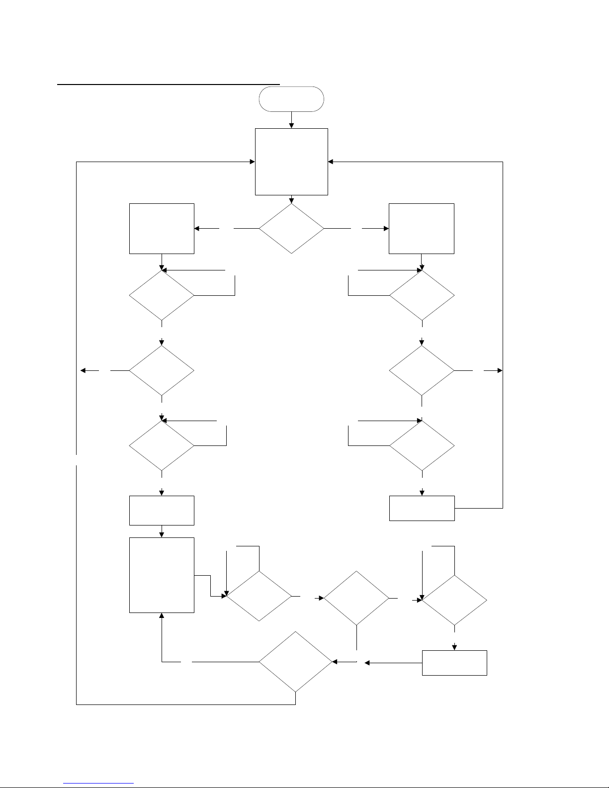
3.3.1 The Stationary Logging Flowchart
The receiver tunes in
the next frequency
from the frequency
Start
table
Timer = 0
Yes
No
Monitor all the
station's antennas
and display 'Ant 0'
Timer = Time
Out?
Yes
Any Signal
Present?
Yes
Timer = Scan
Time?
Yes Yes
Yes No
No No
No
Are there
multiple
antennas?
No
Monitor the
station's
antenna(s) and
display 'Ant 1'
Timer = Time
Out?
Yes
Any Signal
Present?
Yes
Timer = Scan
Time?
No
Store any data
found
Switch to the first
individual antenna
not yet scanned
and display it on
the screen.
Timer = 0
No
Advanced Telemetry Systems, Inc. R4500C Reference User Manual R10-12-A
Store any data
found
No No
Timer = Time
Out?
scanned all the
Yes
Have we
individual
antennas?
Any Signal
Present?
No
Yes
Timer = Scan
Time?
Yes
Store any data
found
28
Page 29
3.4 PC MODE
This Mode is used when communicating with a personal computer (PC). The R4500C needs to be connected to a
PC using the supplied cable. The PC must currently be running the ATS supplied ATSWinRec communication
software. For more information see the sections of this manual covering “Downloading Data” and “ATSWinRec”.
3.5 CLONE
The Clone feature is used to transfer frequency tables and default settings from one receiver to another. The
optional blue clone cable with male DB15 connectors on both ends is required to use this function. Use the
following procedure:
1. Connect the Clone cable between the two re ceivers.
2. Turn both receivers on.
3. Select CLONE on the receiver you want to be the recipient of the data, press “ENTER”.
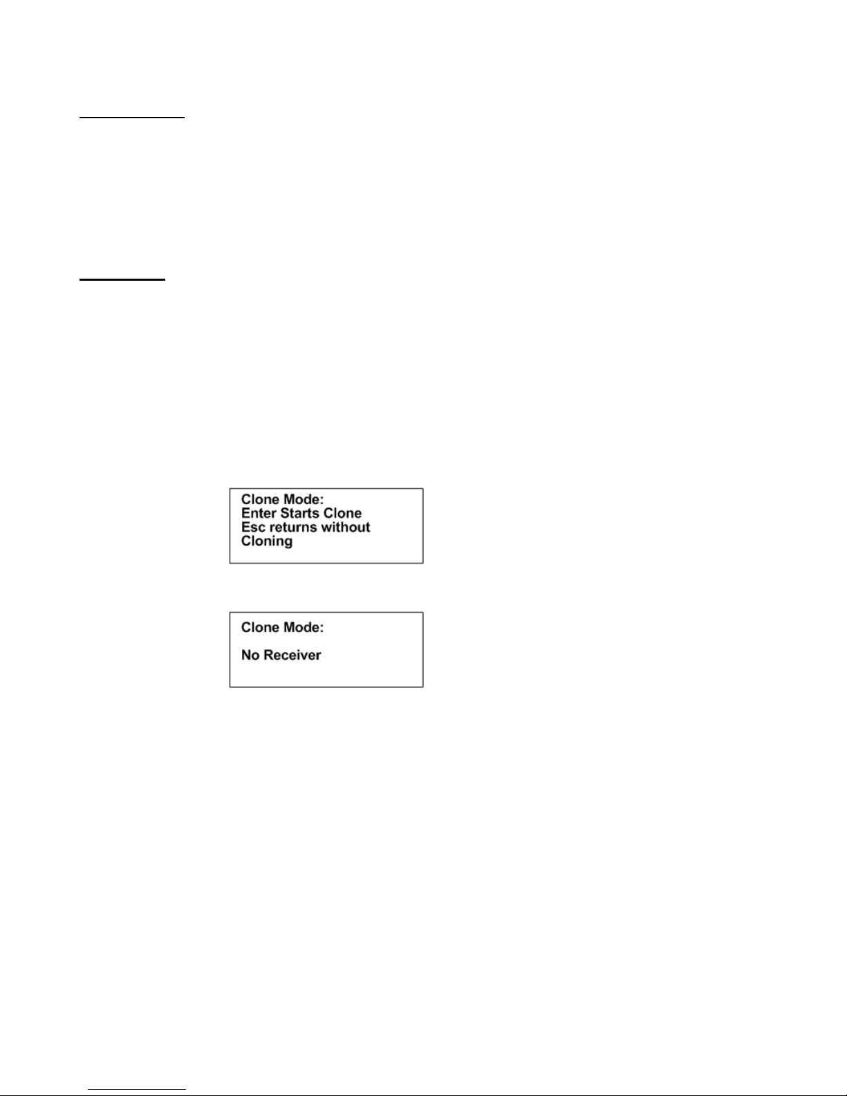
The receiver should respond with:
If a connection cannot be made the receiver will respond with:
If a connection is not made, turn both receivers off and repeat the steps outlined above.
Remember to select CLONE, and then press “ENTER” on the receiver you want to clone the information to.
Advanced Telemetry Systems, Inc. R4500C Reference User Manual R10-12-A
29
Page 30
4.0 SCR – Turning the Screen Backlight On and Off
Pressing the “SHIFT” key followed by pressing the “SCR” key sequentially will turn the backlight on or off
depending on its current state.
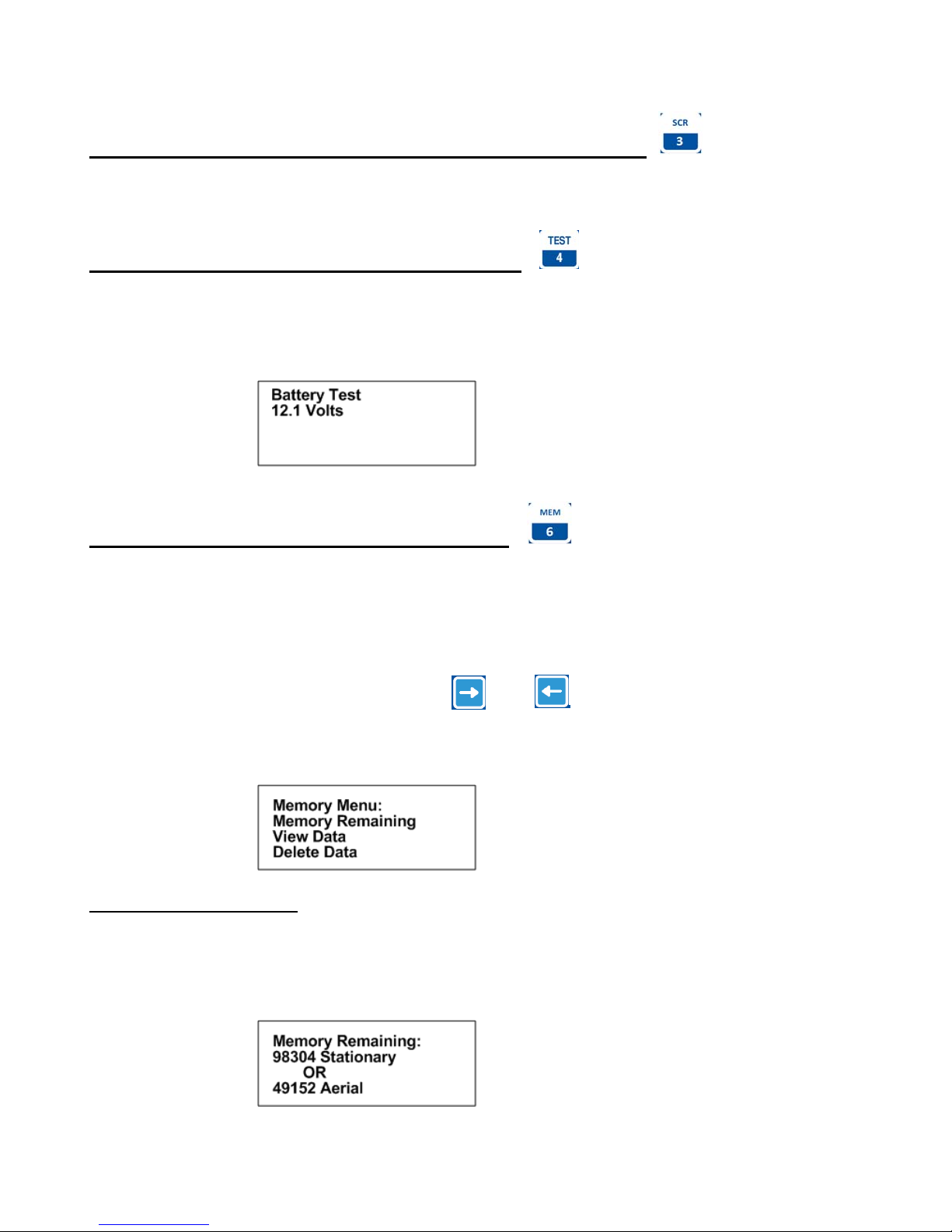
5.0 TEST - View of the “Battery” Voltage
Pressing the “SHIFT” key followed by pressing the “TEST” key sequentially will display the receiver’s power source
voltage. If the power source is the internal battery it will be the internal battery voltage. If it is an external power
source it will be the voltage of the external power source.
6.0 MEM - View of the “Memory Menu”
The Memory Menu is used to view the amount of data storage you have left, look at your stored data and reset your
data pointer.
To get to the “Memory Menu” press the “SHIFT” key followed by the “MEM” key sequentially.
Again to maneuver through the menu items, use the
Memory, or Delete Memory.
This is the view of the “Memory Menu”
6.1 Memory Remaining
This screen displays the number of data blocks the R4500C can still write before the memory is full. It list two
numbers, one for Aerial data and one for Stationary data. The number of Aerial data blocks will always be half as
much as the number of Stationary data blocks. The maximum number of data blocks available for storage is shown
below.
or the keys to choose Memory Remaining, View
Advanced Telemetry Systems, Inc. R4500C Reference User Manual R10-12-A
30
Page 31
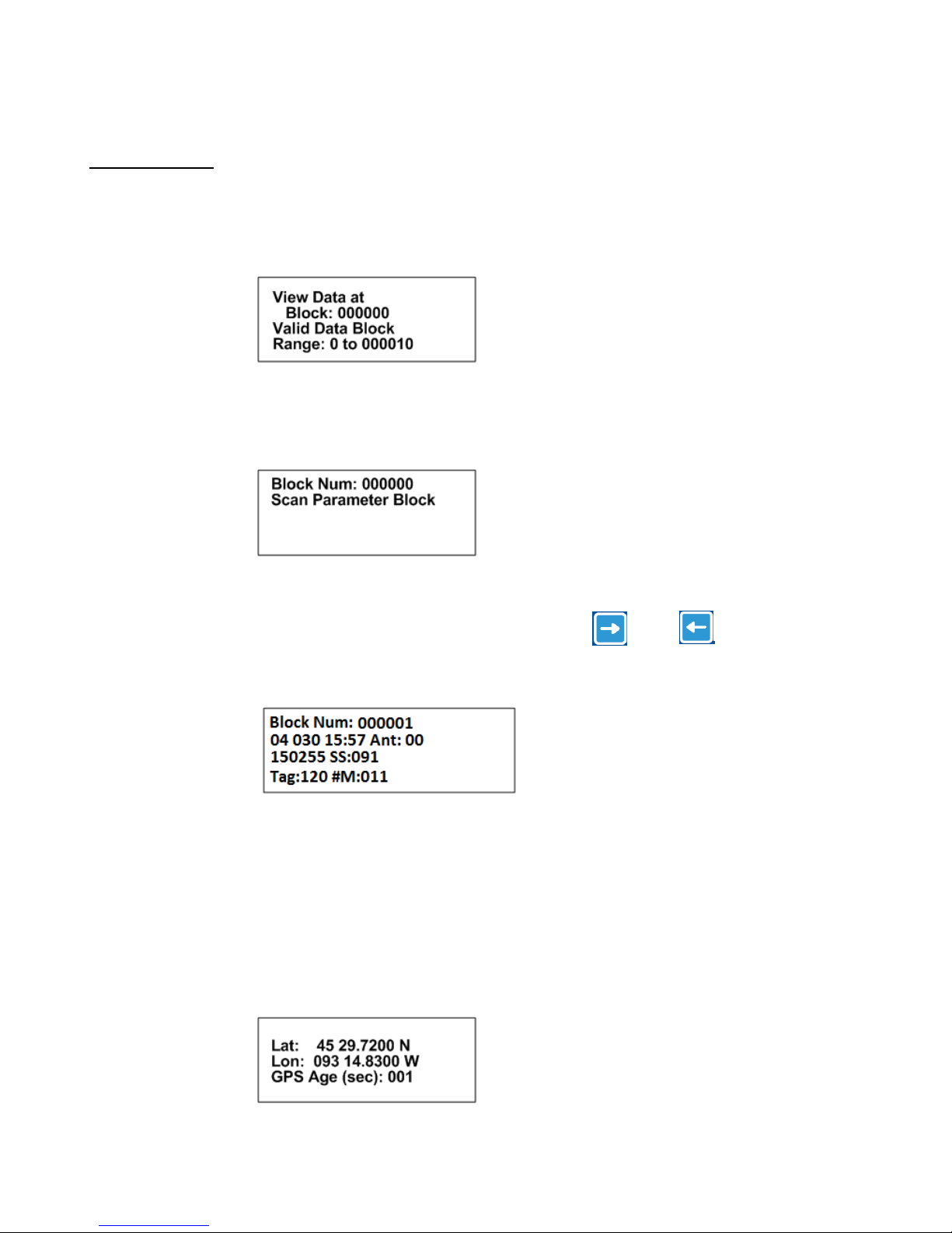
6.2 View Data
This series of screens allows you to view all your previously stored data block by block. The format of the data to be
viewed will depend on the selected “TX Type” and whether it was Aerial or Stationary Logging.
Screen 1
Block: The number of the first data block you want to view. The first data block is zero.
Range: This is the number of data blocks you want to scroll through.
Screen 2
This represents a block of saved parameter data that was used during the following data block
saves. It is not viewable here but can be viewed when offloaded from the PC.
To scroll through the screens displaying the blocks of data, use the
or the keys.
Screen 3
After the Block Number, the next row has the Year, Julian Day, Time, and Antenna used.
Next row: Frequency, and Signal Strength.
Next row: Tag ID (2digit ID followed by a 0, 3 or a 6 where; “0”- non mortality,
“3”-weak mortality signal and “6”:strong mortality signal) , # of detected matches for the
ID listed.
For Aerial Data only:
(A block number is not shown for the 2
nd
screen of Aerial Data)
Advanced Telemetry Systems, Inc. R4500C Reference User Manual R10-12-A
31
Page 32

GPS Age: The amount of time in seconds that have passed since this GPS data had been
recorded.
This sequence of screens will repeat until you have viewed all the data blocks listed in your range or you
press the “ESC” key.
6.3 Delete Data
This instructs the R4500C to reset the data pointer back to the beginning of memory effectively deleting all the
stored data blocks.
Screen 1
Screen 2
Screen 3
This message flashes momentarily then returns you back to the “Memory Menu”.
Advanced Telemetry Systems, Inc. R4500C Reference User Manual R10-12-A
32
Page 33
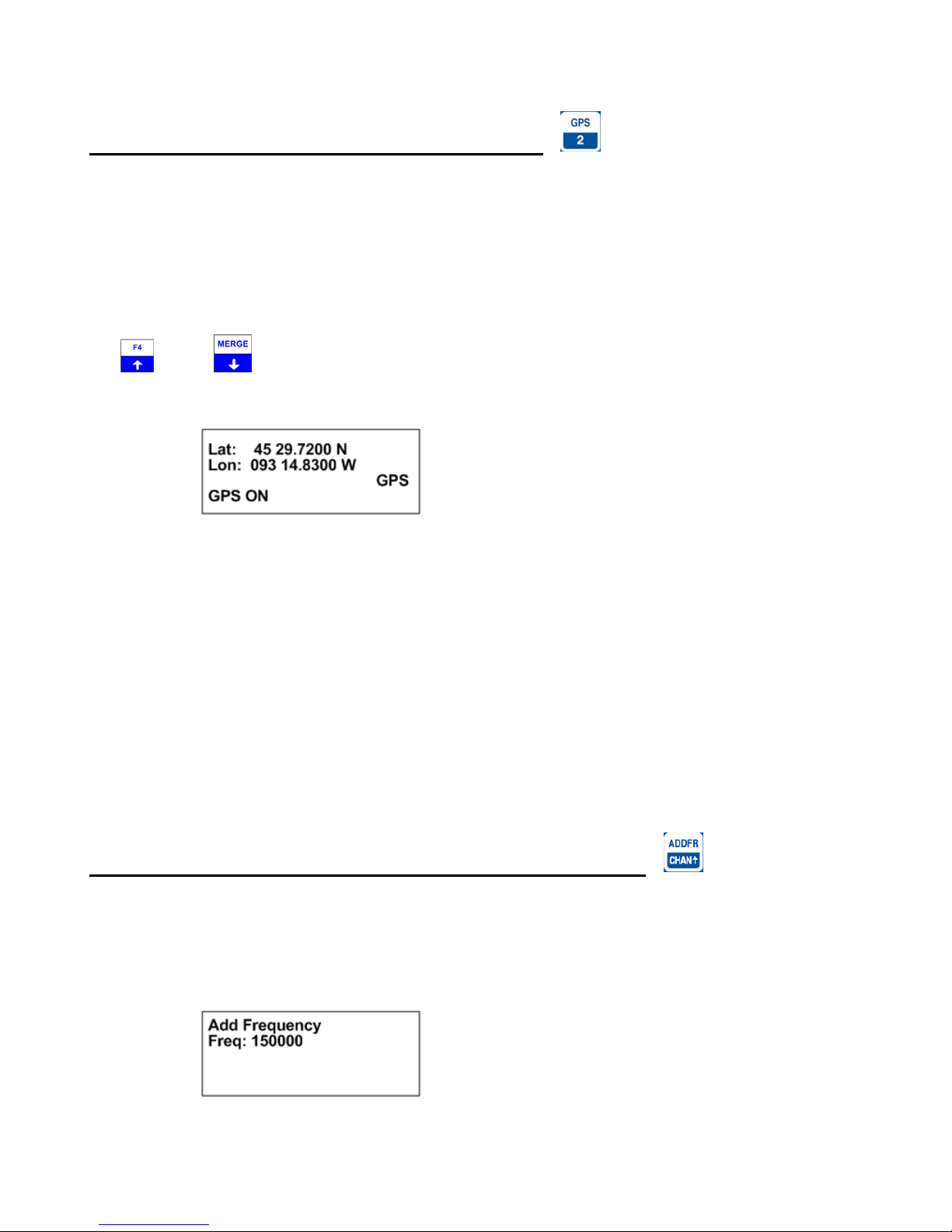
7.0 GPS – Viewing / Activating GPS Data
Pressing the “SHIFT” key followed by pressing the “GPS” key sequentially allows you to view the GPS data as the
data are collected and it allows you to turn the GPS functionality on or off.
The optional GPS antenna needs to be connected to the R4500C to use the GPS feature.
Note: The GPS functionality uses a lot of power. Make sure to turn off the GPS when you are not using it in order to
extend your battery life.
The
Minutes. DD MM.MMMM. The GPS locations saved in memory are stored as Decimal Degrees, or converted to
UTM (NAD83) when using the ATSWinRec software.
GPS (non flashing) – The GPS is on, and there is a valid GPS fix.
GPS / OFF – The GPS is turned OFF.
NO / FIX – The GPS is attempting to acquire a valid GPS fix.
GPS / ERR – The GPS has not been able to get a valid GPS fix within 5 minutes.
NO / GPS – The GPS has not been able to get a valid GPS fix after 15 minutes.
If a valid GPS fix is found during NO /FIX, GPS / ERR, or NO / GPS the indicator will change to a non flashing GPS
indicator.
The GPS requires a current Almanac to obtain a GPS fix (a current almanac is within 6 months). If a current
almanac is needed to be downloaded, this process may take longer than 15 minutes and a fix will not be obtainable
until a current almanac is downloaded.
and the keys are used to turn GPS on or off. The coordinates are displayed as Degrees – Decimal
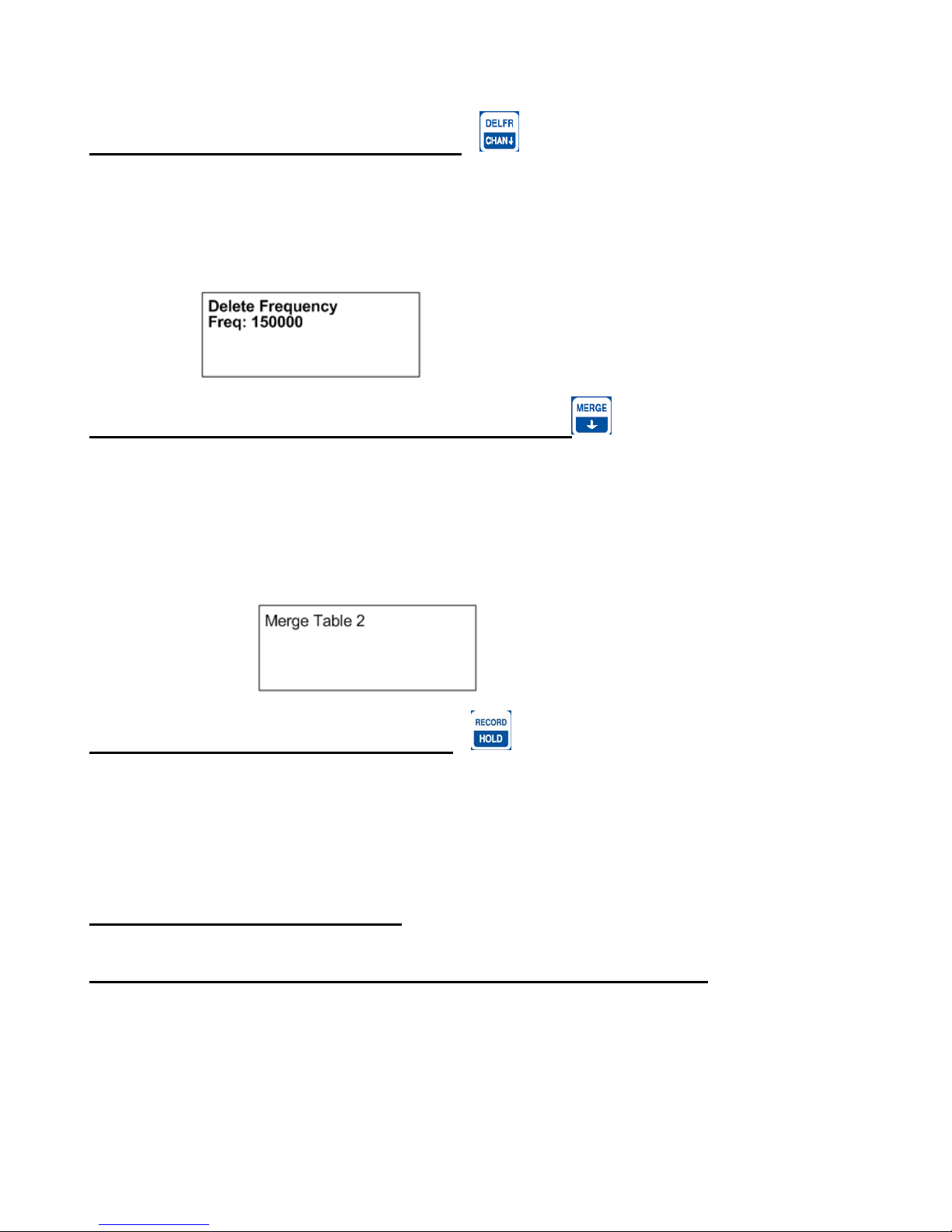
8.0 ADDFR – Adding a Frequency to the Scan Table
(Used only in Aerial Mode)
Pressing the “SHIFT” key followed by pressing the “ADDFR” key sequentially activates the add frequency feature.
This allows you to append frequencies to your current scan table. Changes will be maintained if you exit Aerial
Mode and return to the Aerial Scan using the Resume Last Scan option.
Advanced Telemetry Systems, Inc. R4500C Reference User Manual R10-12-A
33
Page 34
9.0 DELFR - Deleting Frequencies
(Used only in Aerial Mode)
Pressing the “SHIFT” key followed by pressing the “DELFR” key sequentially activates the delete frequency
feature. This allows you to delete frequencies from your current scan table. Changes will be maintained if you exit
Aerial Mode and return to the Aerial Scan using the Resume Last Scan option.
10.0 MERGE – Merging Frequency Tables
(Used in Stationary and Aerial Modes)
Pressing the “SHIFT” key followed by pressing the “MERGE” key sequentially activates the merge frequency
feature. This allows you to merge an additional frequency table into to your current scan table. Changes will be lost
once you exit the Stationary scan but maintained if you exit Aerial Mode and return to the Aerial Scan using the
Resume Last Scan option.
11.0 RECORD – Recording Data
(Used only in Aerial and Manual Modes)
Pressing the “SHIFT” key followed by pressing the “RECORD” key sequentially activates the record feature. This
forces a save to be preformed when a save would not ordinarily be done. The R4500C will save the data it has
currently available.
12.0 PC - Downloading Data
12.1 Establish communication between the R4500C and the Computer
First install the provided software, ATSWinRec, and the USB drivers located in the CP210x_VCP folder (choose the
one right for your operating system) onto your computer. This program needs to be operating on the computer first,
for the R4500C to recognize a PC connection.
Advanced Telemetry Systems, Inc. R4500C Reference User Manual R10-12-A
34
Page 35

The setup should start automatically, if it does not, select START, RUN, BROWSE to find the SETUP file on the
CD, then OPEN and OK. Run the setup to install the ATSWinRec program. It will install a short cut icon on your
desktop.
12.2 Com Port (Settings Menu)
This is the communications port (Com Port) that you have selected to communicate from your personnel computer
to the R4500C. You will need to use a standard USB A Male to USB Mini communication offload cable which is
provided to you by ATS. The first time you start ATSWinRec after installation you'll be asked to select a Com port
from a provided list. This is a list of communication ports currently residing on your computer. After the selection is
made it will be the default Com port selected during subsequent sessions using ATSWinRec. The Com Port can be
changed by selecting “Com Port” from the “Settings” menu and selecting a new Com Port from the list prov ided.
This selection will then be the new default selection.
Connect the provided USB Serial Cable to a USB port on the computer, and to the PC connector on the R4500C.
With the ATSWinRec program running on the computer, move the R4500C cursor to the PC position while in the
R4500C Program Menu. Presses “ENTER” on the R4500C.
The R4500C display will change to:
And then to:
If communication is not successful:
1. Check that both ends of the offload cable are plugged in. The male end of your cable plugs into a USB
port of your computer and the USB Mini end plugs into the R4500C’s USB connector labeled “PC”.
2. Verify that the selected Com Port matches the PC Com Port that is currently assigned to your USB serial
convertor. This can be done by going into your Device Manager and looking under the Port s (COM & LPT)
directory.
3. Make sure that the R4500C is powered up.
4. Make sure that you are in the R4500C’s “PC Mode” and that the screen reads “Active”. Choose “PC
Mode” by selecting “PC” from the “Program Menu” of the R4500C. This needs to be done while you are
connected to your PC and after you have booted up the ATSWinRec program.
Advanced Telemetry Systems, Inc. R4500C Reference User Manual R10-12-A
35
Page 36
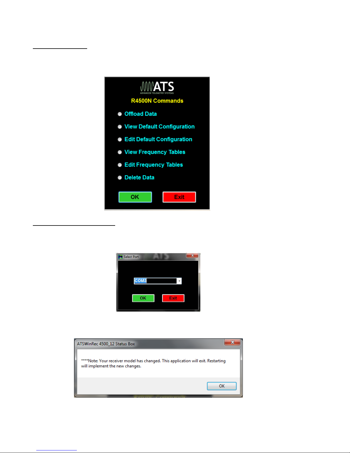
12.3 ATSWinRec
The main screen of the ATSWinRec program has the following command box that will appear in the center of the
screen:
12.3.1 First Time Start Up
When starting the ATSWinRec program for the first time you will be prompted for a com port with the following
dialog box:
It is also possible that you may also get the following dialog box:
This is a notification that the software has readjusted to the R4500C receiver model.
Advanced Telemetry Systems, Inc. R4500C Reference User Manual R10-12-A
36
Page 37
12.3.2 Offloading Data
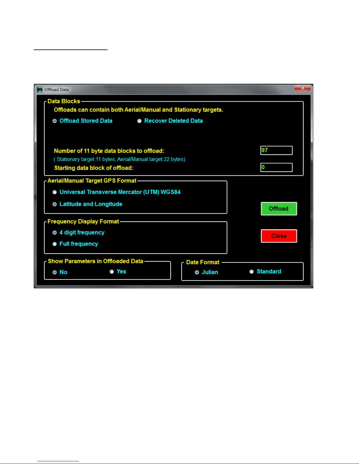
If you select Offload Stored Data followed by OK, the following screen then appears:
You can select some of the offload parameters. Most are self explanatory.
Recover Deleted Data allows you to recover deleted data. When deleting data, a data pointer that is used to store
memory in the R4500C is reset, and when recovering deleted data, the data pointer can be returned to the previous
location. Thus data can be recovered if the data has not been overwritten by resetting the pointer. When the
R4500C memory is maxed out, the newest data will start writing over the oldest data blocks. Recovering deleted
data will only work for the last data set deleted.
You may also set the starting data block to be greater than zero. For example you may only want to check the most
recent data.
You can select the coordinate for the GPS data.
You can select the frequency data displayed with all six digits or with the two most significant digits suppressed.
Advanced Telemetry Systems, Inc. R4500C Reference User Manual R10-12-A
37
Page 38
Showing parameters in the offloaded data. This feature allows the data to include the scan parameters for each
scan started when offloading the data. When this feature is not selected, the offloaded data will not have any scan
parameters showing in the offloaded data.
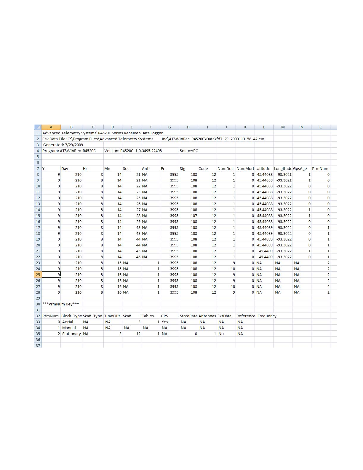
The figure below shows downloaded data with first an Aerial Scan, then a Manual Scan, then a Stationary Scan.
The last column is an index into the parameter table displayed at the end of the data. The parameter number 0
appears here in lines 8 – 16. The parameter settings for those data points are displayed on line 33. To have this
extra information appear in your offloaded data you need to select yes in the “Show Parameters in Offloaded Data”
box of the offload screen.
Steps for Offloading:
1. To offload the data, make sure the Offload Stored Data button is checked (default position on start
up). Select any other format options and select “OK”.
2. Selecting the “OK” button will start the data download. Another window will pop up showi ng the
progress of the download.
Advanced Telemetry Systems, Inc. R4500C Reference User Manual R10-12-A
38
Page 39
3. When the Data Download is complete, a window will appear asking if you would like the data
deleted from the receiver. If you do delete the data, and later realize that you did not want to delete
the data, the “Recover Deleted Data” tab can be used to recover the last data set deleted. The
deleted data is only retrievable as a downloaded file using ATSWinRec.
4. Next will be a window that prompts the user for a file name. The default file name is a date
stamped file name. The file is stored in a Data folder. The location will be where the ATSWinRec
was installed to. The default location is:
C:\ Advanced Telemetry Systems, Inc\ATSWinRec_4500_12\Data
5. After saving the file, a new window will appear displaying the downloaded data. A spreadsheet
program can be used to display the downloaded data. When viewing offloaded data with the
ATSWinRec software, sorting data or filtering data is not available and printing is not available.
Using a spreadsheet program (e.g. Excel) will allow sorting and filtering of data.
12.3.3 View / Edit Default Configuration
The screens will be the same for viewing or editing the default configuration. In the View Default Configuration
mode, no parameters can be modified.
Advanced Telemetry Systems, Inc. R4500C Reference User Manual R10-12-A
39
Page 40
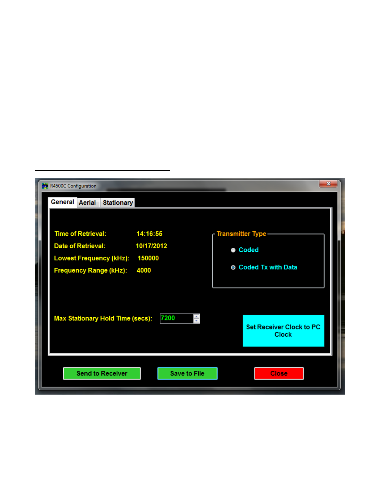
Only the selections in blue and the numeric entries in green can be modified. No information will be saved, unless
the green or blue buttons are selected; Save to File, Send to Receiver or Set Receiver Clock to PC Clock. See
section 2.3 Defaults for information on each configuration parameter.
All default configurations can be retrieved from the receiver or from a file, and sent to the receiver or saved to a file.
If no configuration was sent to the receiver or saved to a file, selecting Close will not save any changed values.
When selecting the Set Receiver Clock to PC Clock button, the PC time is sent to the R4500C and is converted
to: Year, Julian Day, and 24 hour time format.
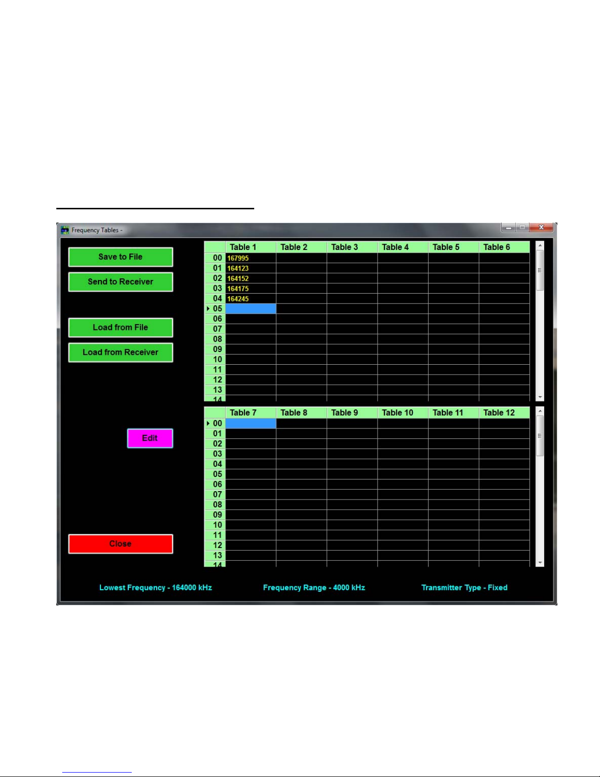
12.3.4 View / Edit Frequency Tables
The screens will be the same for viewing a frequency table or editing a frequency table. In the View Frequency
Tables mode, no parameters can be modified.
Advanced Telemetry Systems, Inc. R4500C Reference User Manual R10-12-A
40
Page 41
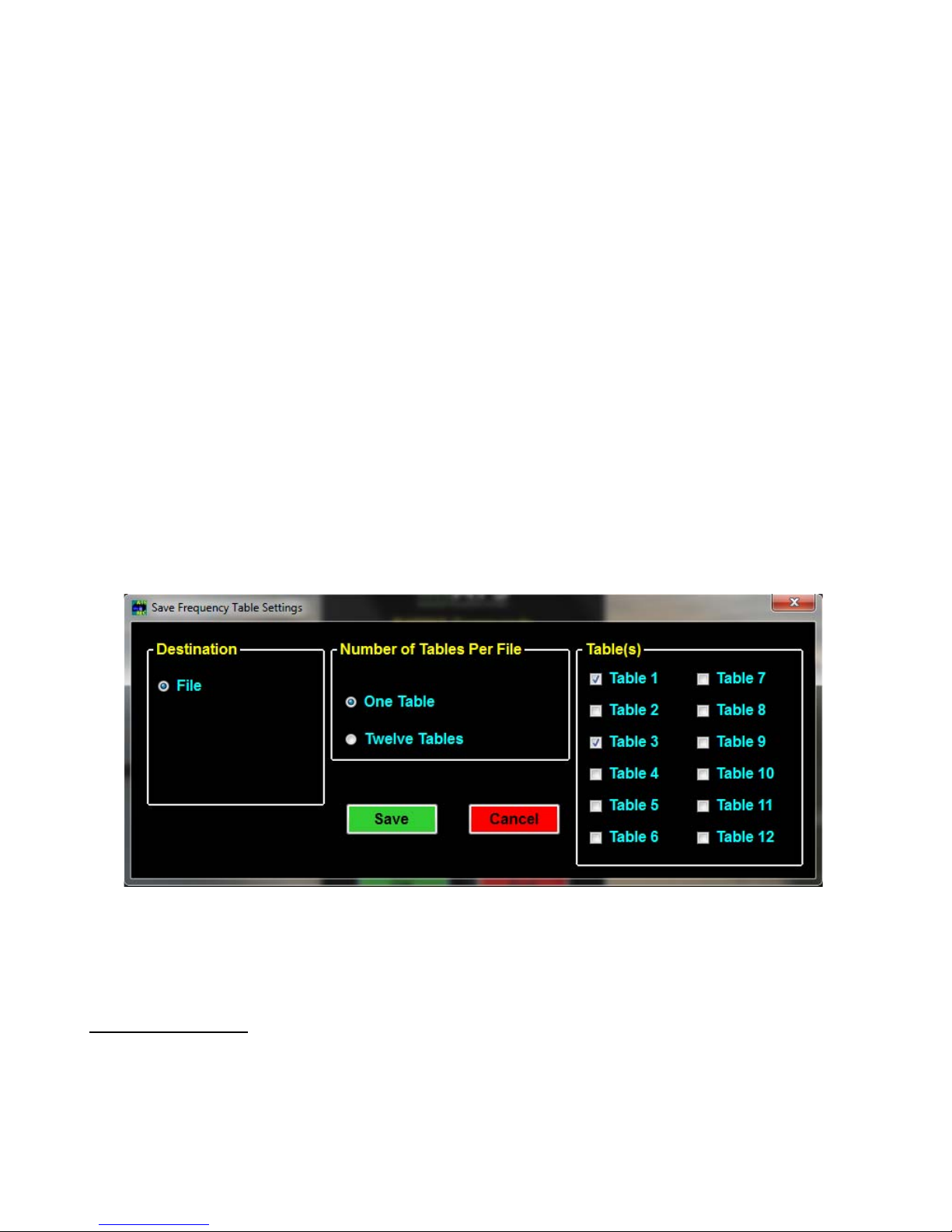
When editing a frequency table the source can be; from a file, from a receiver connected the PC, or a new
frequency table can be created using ATSWinRec. A group of twelve tables can be entered for editing, or a single
table can be entered for editing.
The frequency files are saved as a group (12 tables) – FileName_grp.csv or as a singl e table – Filename_tbl.csv.
Group Frequency Tables
When opening a file of 12 frequency tables, ATSWinRec will be looking for a file with the extension *_grp.csv. A
single frequency table file (file name with extension *_tbl.csv) will not be allowed to be opened.
When sending a group (12 tables) of frequency tables to the receiver only tables with frequencie s will be sent.
Also, the option to only send selected tables to the R4500C is available by deselecting any frequency table tabs not
wanting to be sent.
Single Table Frequencies
When opening a file for a single frequency table, ATSWinRec will be looking for a file with the extension *_tbl.csv.
A group table file (file name with extension *_grp.csv) will not be allowed to be opened.
If a file is saved as a single table, the file can be loaded to any selected frequency table and sent to the receiver by
selecting the corresponding frequency table checkbox. When loading a single table from a file or saving a single
frequency table to a file, each table selected to be loaded or saved, will have a “Windows” open file dialog box for
each file. The figure below is selecting the frequency tables 1 and 3 to be handled as single tables.
If a receiver is not connected to the PC when a new frequency table is created, the lowest frequency of the receiver
will need to be entered. If the wrong lowest frequency is entered when creating a new frequency table, the table
will not be sent to the receiver and an error message will appear indicating that the lowest frequencies do not
match.
12.3.5 Delete Data
Selecting Delete Data will delete the data in the receiver. Warning messages will appear in case if the tab was
accidentally selected.
Advanced Telemetry Systems, Inc. R4500C Reference User Manual R10-12-A
41
Page 42
12.3.6 EXIT
To exit from the ATSWinRec program select:
Exit, then OK
13.0 Setting Aerial Scan Rate
The minimum Aerial Scan Rate should be set to allow for a single code from the transmitter to be heard.
So, for a transmitter with a period of 2000 ms, the minimum scan rate should be set for 2 seconds so at least one
code will be heard.
You may use the CHAN up
scanning or while in Hold. The Chan up and Chan down keys override the Scan Rate time.
The SIG LED should not be used to detect pulses while in the Aerial Mode. The DSP requires 2 pulses to verify a
signal. The first pulse heard will not be shown with a flashing LED, only the second pulse and all other consecutive
pulses will have an LED flash corresponding to a detected pulse. Only when Hold is used or a long enough scan
rate is used, will there be enough time for multiple pulses and for the SIG LED to flash for every detected pulse.
and CHAN down keys at any time to scroll through the channels while
14.0 Setting Stationary Time Out
The minimum stationary Time Out time should be set the same way as setting the Aerial Scan Rate. At least one
coded pulse burst (three beeps) is needed to be detected during the Time Out time, to trigger the Scan Time. If a
full pulse burst is not detected during the Time Out, the R4500C will not determine a tag is present, and move on to
the next frequency during a stationary scan.
The Time Out can be set for longer than the recommended minimum setting. Setting the right Time Out will
depend on the size of the frequency table, and how quickly the table should be cycled through.
15.0 Setting Stationary Scan Time
The minimum stationary Scan Time needs to be set for a valid tag ID to be detected, and to take into consideration
how many tags are expected to be co located. The more tags located in the same area, the longer the scan time is
needed to identify all of the tags.
For a single tag to be identified, three pulse bursts are required. For an ID code 24 tran smitter, the period length is
1310 (ms) / 1000 = 1.310 seconds. For three pulse bursts, the time would be 3*1.310 = 3.93 seconds. The
minimum scan rate should be set for 4 seconds to allow decoding of the ID for a single transmitter. If more tags are
located in the same area on the same frequency, the scan time would need to be set longer than 4 seconds. To
identify 6 tags, 12 seconds should be used. To identify more than 6 tags, a longer scan time will be needed. The
more tags located at the same time, the more time is needed to process all of the incoming pulses to identify
transmitter ID’s.
Advanced Telemetry Systems, Inc. R4500C Reference User Manual R10-12-A
42
Page 43

16.0 Offloaded Data Format
Heading – The offloaded file heading identifies the file
Model: The model of the receiver that was offloaded.
Filename: The name of the file with the personal computer drive and folders included.
Version: The version of ATSWinRec used to create this file.
Date: The date the file was originally created.
Source: Indicates whether the data was offloaded via a PC or a PDA.
Column Headers – Lists the name of each column field.
Date – The date each point was recorder.
YY,JJJ,HH,mm, The offload used the Julian Date Format.
or
MM/DD/YYYY HH:mm, The offload used the Standard Date Format.
YY: A number from 0-99 representing the last two digits of the year.
YYYY: A number from 0-9999 representing the year.
JJJ: A number from 1-366 representing the Julian day (1-366 for a leap year, otherwise 1-365).
MM: A number from 1-12 representing the month.
DD: A number from 1-31 representing the day of the month.
HH: A number from 0-23 representing the hour.
mm: A number from 0-59 representing the minute.
Stationary Data – The data stored while the R4500C was loggi ng data in Stationary Mode.
A: A number from 0-8 representing the antenna being used. A ‘0’ indicates all antennas were turned on.
(FF)FFFF: A number representing the transmitter’s frequency. Either it will be 6 digits representing the entire
frequency or it will be a number from 0-9999 representing the last four digits of the frequency.
nn: A 2 digit number from 0-99 representing the tag ID.
mmm: A 3 digit number from 0-255 representing the number of detections with a mortality indicator.
TTT: A number from 40-154 representing the signal strength.
ddd: A number from 1-255 representing the duplicate count for the ID during the store period.
Aerial Data – The data stored while the R4500C was logging in either Aerial or Manual Mode.
SS: A number from 0-59 representing the sec ond.
(FF)FFFF: A number representing the transmitter’s frequency. Either it will be 6 digits representing the entire
frequency or it will be a number from 0-9999 representing the last four digits of the frequency.
nn: A 2 digit number from 0-99 representing the tag ID.
mmm: A 3 digit number from 0-255 representing the number of detections with a mortality indicator.
(-)LL.LLLLLLLL: A
XXXXXXXX.X:
(-)lll.llllllll: A number representing either Longitude or the Y coordinate for UTMs (Universal Transverse
or Mercator).
YYYYYYYY.Y:
TTT: A number from 40-154 representing the signal strength.
number representing either Latitude or the X coordinate for UTMs (Universal Transverse Mercator).
or
ZZZ: This will appear only if UTMs were selected and represents the UTM zone.
AA: A number in seconds from 0-119 representing how long ago the GPS coordinates were recorded.
__________________________________________________________________________
Advanced Telemetry Systems, Inc. R4500C Reference User Manual R10-12-A
43
Page 44

When offloading data and showing parameters in the offloaded data, there will be a parameter number appearing in the last
column. Find that number under the “***PrmNum Key ***” appearing at the bottom of the offload. Cross referencing this will let
you know what parameters was used for each data point that was recorded. Each column has a short descriptive he ader.
Expand the columns to read what each parameter field is.
Below are the column headers followed by some examples:
Column Headers:
PrmNum, Block_Type, Scan_Type, TimeOut, Aerial_TimeOut, Scan, Tables, GPS, StoreRate, Antennas, ExtData,
Reference_Frequency
Parameter Examples:
0, Aerial, Coded Tx, NA, 2, 3.5,1, Yes, NA, NA, NA, NA
1, Stationary, CodedTx, 2 , NA, 12, 1, NA, 0, 1, No, No
2, Stationary, CodedTx, 3, NA, 12, 2 3, NA, 10, 1, Yes, No
Advanced Telemetry Systems, Inc. R4500C Reference User Manual R10-12-A
44
Page 45

17.0 Charging the Batteries
The R4500C is using NiMH (Nickel Metal Hydride) batteries. The capacity of the battery pack is 4.0 Amp hours.
The R4500C will operate from internal batteries for approximately 18 hours for stationary mode, and approximately
11 hours for manual and aerial modes while using the GPS.
The batteries can self drain to 80% capacity during a 6 month shelf life.
It is recommended to maintain a charge cycle when storing the receiver for long period s of time. If the charge
capacity of the batteries does not seem to be at full capacity, a couple charge cycles can bring the battery pack
back to full capacity (discharge – charge – discharge – charge)
The charger supplied with the R4500C is a “smart charger”. There is a thermal sensor to detect a full cha rge, and
to shutdown the charge process if the battery pack overheats.
Turn OFF the power to the R4500C when charging the batteries.
When the charger is connected to the R4500C, the charging sequence will start.
A fully depleted battery pack should be charged to full capacity within 5 hours.
Advanced Telemetry Systems, Inc. R4500C Reference User Manual R10-12-A
45
Page 46

18.0 EXT – External Data Output
If the EXT option has been selected the R4500C will send data once an hour out the AUX and the PC/CLONE
ports while stationary logging. If using GOES (Geostationary Operational Environmental Satellites) option, the data
will be sent to the GOES transmitter’s buffer thru a cable attached via the AUX port. While the R4500C is sending
data out its serial ports one or two status screens will be displayed.
Screen 1
This screen indicates the R4500C is starting to send data out. The example above has 8 data blocks in memory to
process. Only valid data blocks will be sent. The number of blocks the R4500C sends may actually be less than 8.
For example there could be informational blocks that contain programming information for your R4500C that would
not be sent.
Screen 2 (GOES option only)
This screen indicates the number of bytes that were sent over versus the number of bytes that the GOES
transmitter sent acknowledges for. If these numbers do not match a “CHECK” will flash on the screen indica ting a
probable system problem. If this happens check your connections. Also make sure your GOES transmitter is turned
on and operating correctly. The GOES transmitter should display the same number of bytes in its buffer.
If the R4500C determines there were more bytes of data to be sent over to the GOES buffer than the GOES
transmitter can transmit, it will save this data for the next hour’s transmission cycle. You should try to set up your
system so that it does not log more data than it can transmit in a 24 hour period. For fixed period logging each data
point will use 11 bytes. For variable period logging each data point will use 11-12 bytes depending on the type of
data being transmitted. Assume an extra 29 bytes overhead for the header and footer of the transmission block.
Check with NESDIS to determine how many bytes your transmission assignment will allow.
Note: When using the GOES option and as long as the R4500C has not filled up it will not lose the data. It will
always try to catch up. In order to save transmission space, the day the data is collected is attached to the
transmission and not to the individual data point. If the back log becomes too large the date information will not
match the day the data was collected.
When using the RDP (Remote Data Platform) option the R4500C will always dump all the data recorded during the
previous hour’s logging.
Even after the R4500C has filled up it will continuing logging. The newest data will be written over the oldest data.
In order for data to actually be lost the data back log would have to be the entire capacity of the data logger which
is over 90,000 data blocks.
You can connect to the PC port using your USB cable or to your AUX port using a special ATS supplied cable from
your PC. By using a communication software such as Microsoft ® HyperTerminal or Symantec’s Procomm Plus
Advanced Telemetry Systems, Inc. R4500C Reference User Manual R10-12-A
46
Page 47

and the serial settings “baud: 9600, no parity, 8 data bits, 1 stop bit” or “baud: 57600, no parity, 8 data bits, 1 stop
bit” you can monitor the data that is sent out. This data comes out in a compressed format that if using GOES is the
same as that you will see when downloading your data from NESDIS or if using the RDP is a compressed format
that when uncompressed is the same as your normal offloaded data.
18.1 Data Format and Translation
18.1.1 BINARY DATA
To maximize the amount of data you can send in a transmission, your data has been compressed into binary data.
The binary data is sent as ASCII text that is viewable in a text editor. The downloaded data will appear in the same
form that it was sent.
Some example GOES data:
350/11:00 122
@@PA@@J@@
A@@@@HB@@
@ATLKhGKy
@ATLKpHKy
@ATLKpHKy
@ATLKpHKy
@ATLKpGKz
@ATLKhHKz
@ATLKhGKz
@ATLKpHKz
@ATLKhHKz
@ATLKhGK{
@ATLKpGK{
@ATLKhGK{
@ATLKhGK{
@ATLKhHK{
@ATLKhHK{
END
Bytes Verified: 0 Total Bytes: 396
Some example RDP data:
350/11:00 124 RDP_C Dump
@P@@@PA@_`@@@@B
@Kxl?qU^BsdA@DD
@KyE?qU^BsdA@DG
@KyF?qU^Bsd@@DG
@Kxp?qU^BsdB@DE
@KyE?qU^BsdA@DE
@KyF?qU^Bsd@@DF
@Kxl?qU^BshA@DE
@KyF?qU^Bsh@@DF
@KyE?qU^BshA@DG
@KyF?qU^Bsh@@DG
@KyF?qU^Bsl@@DG
@KyE?qU^BslA@DI
@KyF?qU^Bsl@@DG
@Kxl?qU^BslA@DE
@KyE?qU^BslA@DH
END
Advanced Telemetry Systems, Inc. R4500C Reference User Manual R10-12-A
47
Page 48

Total Bytes: 629
To view this as more meaningful data you need to run translator program that is provided by ATS on request. The
translated data for the RDP style dump is the same as a normal offloaded data file.
18.1.2 GOES Translated Output Format
1533C4CE08261161223G43+1NN180WFF00424`
Day/Hr:Min Volts Freq Code Ant# Signal Hr:Min #Matches
261/07:00 12.6 150684 16 0 119 7:01 15
261/07:00 12.6 150684 16 1 126 7:08 15
261/07:00 12.6 150684 16 2 95 7:02 5
261/07:00 12.6 150684 16 0 121 7:19 10
261/07:00 12.6 150684 16 1 114 7:19 14
261/07:00 12.6 150684 16 2 106 7:19 12
261/07:00 12.6 150684
261/07:00 12.6 150684 16 1 137 7:25 8
261/07:00 12.6 150684 16 2 120 7:25 7
261/07:00 12.6 150684 16 0 129 7:38 13
261/07:00 12.6 150684 16 1 137 7:38 16
261/07:00 12.6 150684 16 2 122 7:31 15
261/07:00 12.6 150684 16 0 140 7:49 15
261/07:00 12.6 150684 16 1 142 7:49 15
261/07:00
12.6 150684 16 2 121 7:45 8
261/07:00 12.6 150684 16 2 136 7:59 22
261/07:00 12.6 150684 16 0 138 7:59 14
261/07:00 12.6 150684 16 1 137 7:54 15
END
Day: A number from 1-366 representing the Julian day (1-366 for a leap year, otherwise 1-365). This appears in
the transmission header of R4500C and it indicates the day the data was processed for transmission.
Hr: A number from 0-23 representing the hour. This appears in the transmission header of the R4500C and it
indicates the hour the data was processed for transmission. The data is sent from the R4500C at the top of
the hour over to the GOES transmitter. This hour represents the hour previous to the hour the data is sent.
If the transmissions are keeping up with the data collection this will be the same hour as the hour the data
was collected.
Volts: Voltage to the tenths of volts representing the system voltage at the time the data was sent over to the
GOES transmitter. This appears in the transmission header of R4500C.
Freq: A number representing the transmitter’s frequency. It will be a number from 0-9999 representing the last
four digits of the frequency.
Code: The number representing the code of the detected transmitter.
16 0 125 7:25 7
Advanced Telemetry Systems, Inc. R4500C Reference User Manual R10-12-A
48
Page 49

Ant#: A number from 0-8 representing the antenna being used. A ‘0’ indicates all antennas were turned on.
Hr: Min: A number representing the hour and minute this data point was saved to memory.
#Matches: A number from 1-255 representing the number of codes detected during the scan.
END: The END appears at the end of the data sent to the GOES. If it does not appear you know the data
transmission was incomplete and some data was lost.
Advanced Telemetry Systems, Inc. R4500C Reference User Manual R10-12-A
49
Page 50

JULIAN DATE CALENDAR
(PERPETUAL)
Day Jan Feb Mar Apr May Jun Jul Aug Sep Oct Nov Dec Day
1
2
3
4
5
6
7
8
9
10
11
12
13
14
15
16
17
18
19
20
21
22
23
24
25
26
27
28
29
30
31
001 032 060 091 121 152 182 213 244 274 305 335
002 033 061 092 122 153 183 214 245 275 306 336
003 034 062 093 123 154 184 215 246 276 307 337
004 035 063 094 124 155 185 216 247 277 308 338
005 036 064 095 125 156 186 217 248 278 309 339
006 037 065 096 126 157 187 218 249 279 310 340
007 038 066 097 127 158 188 219 250 280 311 341
008 039 067 098 128 159 189 220 251 281 312 342
009 040 068 099 129 160 190 221 252 282 313 343
010 041 069 100 130 161 191 222 253 283 314 344
011 042 070 101 131 162 192 223 254 284 315 345
012 043 071 102 132 163 193 224 255 285 316 346
013 044 072 103 133 164 194 225 256 286 317 347
014 045 073 104 134 165 195 226 257 287 318 348
015 046 074 105 135 166 196 227 258 288 319 349
016 047 075 106 136 167 197 228 259 289 320 350
017 048 076 107 137 168 198 229 260 290 321 351
018 049 077 108 138 169 199 230 261 291 322 352
019 050 078 109 139 170 200 231 262 292 323 353
020 051 079 110 140 171 201 232 263 293 324 354
021 052 080 111 141 172 202 233 264 294 325 355
022 053 081 112 142 173 203 234 265 295 326 356
023 054 082 113 143 174 204 235 266 296 327 357
024 055 083 114 144 175 205 236 267 297 328 358
025 056 084 115 145 176 206 237 268 298 329 359
026 057 085 116 146 177 207 238 269 299 330 360
027 058 086 117 147 178 208 239 270 300 331 361
028 059 087 118 148 179 209 240 271 301 332 362
029 088 119 149 180 210 241 272 302 333 363
030 089 120 150 181 211 242 273 303 334 364
031 090 151 212 243 304 365
1
2
3
4
5
6
7
8
9
10
11
12
13
14
15
16
17
18
19
20
21
22
23
24
25
26
27
28
29
30
31
FOR LEAP YEAR USE OTHER CHART
Advanced Telemetry Systems, Inc. R4500C Reference User Manual R10-12-A
50
Page 51

JULIAN DATE CALENDAR
(FOR LEAP YEARS ONLY)
Day Jan Feb Mar Apr May Jun Jul Aug Sep Oct Nov Dec Day
1
2
3
4
5
6
7
8
9
10
11
12
13
14
15
16
17
18
19
20
21
22
23
24
25
26
27
28
29
30
31
001 032 061 092 122 153 183 214 245 275 306 336
002 033 062 093 123 154 184 215 246 276 307 337
003 034 063 094 124 155 185 216 247 277 308 338
004 035 064 095 125 156 186 217 248 278 309 339
005 036 065 096 126 157 187 218 249 279 310 340
006 037 066 097 127 158 188 219 250 280 311 341
007 038 067 098 128 159 189 220 251 281 312 342
008 039 068 099 129 160 190 221 252 282 313 343
009 040 069 100 130 161 191 222 253 283 314 344
010 041 070 101 131 162 192 223 254 284 315 345
011 042 071 102 132 163 193 224 255 285 316 346
012 043 072 103 133 164 194 225 256 286 317 347
013 044 073 104 134 165 195 226 257 287 318 348
014 045 074 105 135 166 196 227 258 288 319 349
015 046 075 106 136 167 197 228 259 289 320 350
016 047 076 107 137 168 198 229 260 290 321 351
017 048 077 108 138 169 199 230 261 291 322 352
018 049 078 109 139 170 200 231 262 292 323 353
019 050 079 110 140 171 201 232 263 293 324 354
020 051 080 111 141 172 202 233 264 294 325 355
021 052 081 112 142 173 203 234 265 295 326 356
022 053 082 113 143 174 204 235 266 296 327 357
023 054 083 114 144 175 205 236 267 297 328 358
024 055 084 115 145 176 206 237 268 298 329 359
025 056 085 116 146 177 207 238 269 299 330 360
026 057 086 117 147 178 208 239 270 300 331 361
027 058 087 118 148 179 209 240 271 301 332 362
028 059 088 119 149 180 210 241 272 302 333 363
029 060 089 120 150 181 211 242 273 303 334 364
030 090 121 151 182 212 243 274 304 335 365
031 091 152 213 244 305 366
1
2
3
4
5
6
7
8
9
10
11
12
13
14
15
16
17
18
19
20
21
22
23
24
25
26
27
28
29
30
31
(USE IN 2016, 2020, 2024, ETC.)
Advanced Telemetry Systems, Inc. R4500C Reference User Manual R10-12-A
51
Page 52

Advanced Telemetry Systems, Inc. R4500C Reference User Manual R10-12-A
52
 Loading...