

Page 1

RECEIVER MODELS R2000/R2100/R4000
User’s Manual
Page 2

Table of Contents
INTRODUCTION 1
RECEIVING PROCEDURES 1
CONNECTIONS 2
INTERACTING WITH THE RECEIVER 4
RECEIVER CONTROLS 4
Receiver Models R2000 and R2100 5
Receiver Model R4000 8
RECEIVER INDICATORS 11
PROGRAMMING THE RECEIVER 13
To Add a Frequency to Memory 13
To Delete a Frequency from Memory 14
To Program All Frequencies into the Memory 14
To Delete All Frequencies from Memory 15
To Choose the Scan Rate 15
SCANNING FREQUENCIES STORED IN MEMORY 16
To Start Scanning 16
To Delete a Frequency from Memory while Scanning 16
To Rapidly Move through Frequencies Programmed in Memory 16
To Stop Scanning 16
RECEIVER OPERATIONS 17
INTERPRETING THE DATA 19
Page 3

POWER CONSIDERATIONS 19
MAINTENANCE 20
APPENDIX A - WARRANTY 21
APPENDIX B - PROCEDURE FOR TUNING TRANSMITTERS 22
APPENDIX C - ADJUSTING THE THRESHOLD CONTROL 23
APPENDIX D - QUESTIONS ?? 24
APPENDIX E - RECEIVER SPECIFICATIONS 25
This device complies with Part 15 of the FCC Rules.
Operation is subject to the following two conditions: (1)
This device may not cause harmful interference, and (2)
This device must accept any interference received,
including interference that may cause undesired
operation.
copyright© 1993 by Advanced Telemetry Systems, Inc. (ATS) All rights reserved. No part of
this manual may be reproduced in any form (electronic, mechanic, photocopy, or other)
without prior permission in writing from ATS.
Page 4
page 1
INTRODUCTION
Thank you for purchasing an Advanced Telemetry Systems’ receiver. Our receiver is a
radio frequency receiver which comesin a 2 MHzor 4 MHz version. The receiver can be
programmed to scan frequencies or you can manually tune it. There are three models of
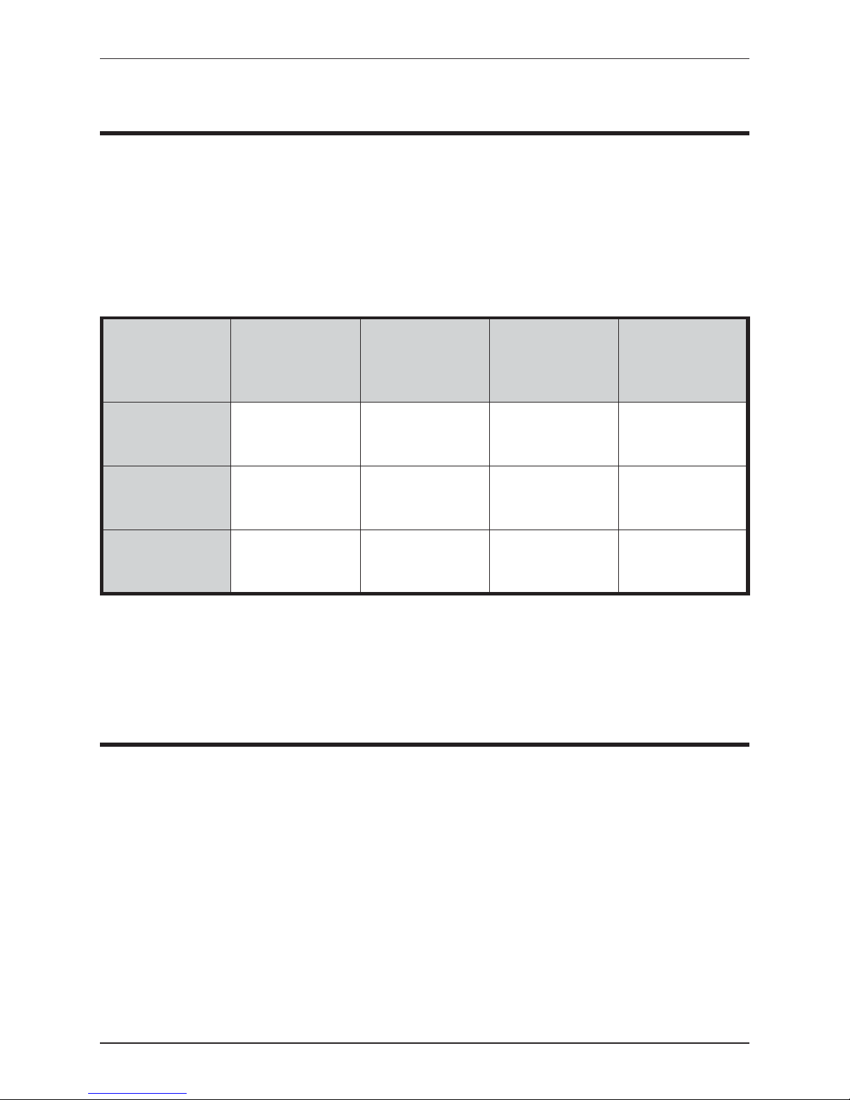
our scientific receiver. Table 1 demonstrates the differences of the three.
MODEL CHANNELS SIGNAL
DETECTION
METHOD
R2000
R2100
2000 AUDIO ONLY 1 NO
2000 AUDIO/TONE
DECODER
R4000
4000 AUDIO/TONE
DECODER
Table 1 - Differences in Receiver Models
As you notice, only model R2000 does not contain a tone decoder. A tone decoder is
needed when the receiver is used with a data collection computer to create an automatic
data collection system.
MEMORY
BANKS
1 YES
4 YES
COMPUTER
INTERFACE
Operationally, the receiver works by acting as a filter to select a very narrow window in
the frequency spectrum. The position of this filter in the frequency spectrum is
determined by the frequency selection (tuning). The receiver rejects signals and noise
outside the filter window and passes signals and noise within the window. Additionally,
the receiver translates the signal to a frequency withinthe hearing range. For all receiver
models, you can listen to what the receiver is picking up. Otherwise, you can use the
tone decoder to see what the receiver is picking up. If the tone decoder picks up a
transmitter’s signal, a plus sign (+) will flash on the receiver’s display to the left of the
frequency. In order for the tone decoder to work, the audio controlmust be turned off.
Advanced Telemetry Systems, Inc. R01-02-A Receiver Manual
RECEIVING PROCEDURES
Page 5
page 2
Using either the tone decoder or the audio, the receiver can be tuned manually or
programmed to scan a set of frequencies at a set interval.
CONNECTIONS
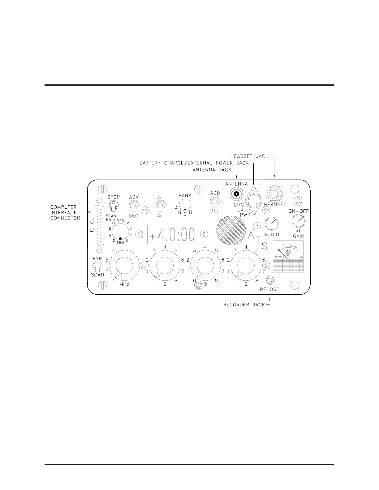
ATS receivers have five connectors except the model R2000 which has four. Figure
1 displays those connectors.
Figure 1 - Receiver Connections (Model R4000 shown)
·
Antenna Jack
To connect an antenna to the receiver use the antenna jack. This jack requires
a BNC connector to attach an external antenna.
·
Battery Charge/External Power Jack
Receiver Manual R01-02-A Advanced Telemetry Systems, Inc.
Page 6

page 3
The Charge/Ext Power jack serves two purposes, as its name states. To
charge the receiver’s internal batteries, plug the charger in here. When the
receiver’s batteries are not charging, this jack can be used to power the
receiver externally.
Using an external power cord, connect the external power source (11.5 15VDC) to the receiver. When an external power source is used, the receiver
automatically switches from internal to external power. With Model R2000
receivers, you can hear a click when the receiver’s relay switches from its
internal batteries to an external power source.
NOTE: Having external power connected to the receiver will not recharge the
receiver’s internal batteries. To recharge the receiver’s internal batteries, plug
the battery charger ATS supplied into the receiver’s CHG EXT PWR jack
when the receiver is not operating.
An external power source can be a deep cycle marine battery, a solar panel, a
cigarette lighter in a car, a gell cell battery, etc. Please note that ATS can
provide you with the different cables needed to connect to external power
sources.
Be sure the receiver is off when disconnecting the external power source. If
the receiver is on, the receiver will revert to internal power and drain its
batteries.
NOTE: Standard receivers use a 3-pin external power cord. Older receivers
(purchased before April 1991) with the “computer controlled on/off” option
require an external power cord with a 5-pin connector. These receivers have a
toggle switch in their record jack (labeled “REC” and located in the lower
right-hand corner of the receiver’s faceplate).
·
Computer Interface Connector
If you are using a Data Collection Computer (DCC), connect the receiver to
the DCC via a ribbon cable attached to this connector.
The DCC will be programmed to control the receiver’s operation, interpret
the data received by the receiver, and store this data along with the date and
time. Having a DCC interfaced with the receiver produces an automatic
datalogging system.
·
Headset Jack
Advanced Telemetry Systems, Inc. R01-02-A Receiver Manual
Page 7

page 4
To listen to the receiver’s audio signal through a headset, plug the headset
into the receiver’s headset jack. When a headset is connected, the receiver’s
speaker is disabled. The headset jack accepts a standard 1/4" monaural plug.
Standard stereo plugs are also acceptable if both head pieces are wired to the
tip. Impedance into the headset jack is approximately 8 ohms. Headsets with
impedances of 8 to 2000 ohms may be used.
Recorder Jack
·
Plug a 0-1mA external recorder (ex. 0-1mA Model 288 Rustrak recorder)
into the receiver’s recorder jack . This jack requires a 1/8" diameter plug
(switchcraft #750). The recorder jack connects the external recorder in series
with the receiver’s signal meter for chart recording. The external meter
option is designed to read accurately for a 100 ohm external meter.
INTERACTING WITH THE RECEIVER
Most receivers contain three types of toggle switches on their faceplates. The three
types are locking toggle, momentary toggle, and regular toggle switches. To move a
locking toggle switch from its current position, you must pull up on the toggle and then
move it. Locking toggles are often used for the on/off power control so that the power
cannot be turned on or off inadvertently. A momentary toggle switch canbe movedfrom
its current position by pushing on it but it will always flip back to its former position.
This type of toggle switch is always used for delta tune, add/del, and adv/dec switches
because you do these functions one at a time. The regular toggles are moved by pushing
them into the desired position. Regular toggles will stay in the position you move them
to.
RECEIVER CONTROLS
This two-part section discusses each of the receiver’s controls. The first part covers the
receiver models R2000 and R2100. The second partcovers thereceiver modelR4000.
Receiver Manual R01-02-A Advanced Telemetry Systems, Inc.
Page 8
Receiver Models R2000 and R2100
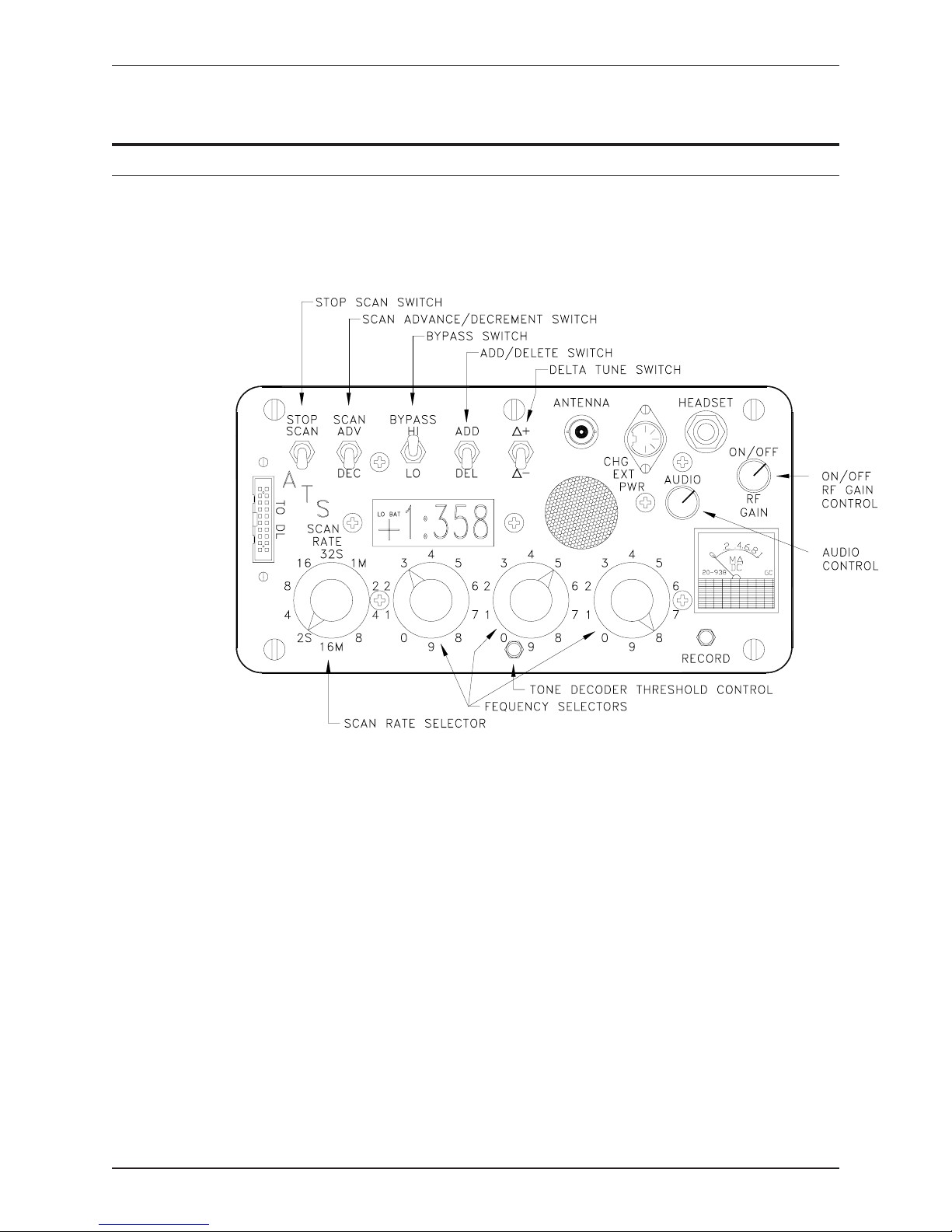
Refer to Figure 2 for the locations of the controls.
page 5
·
Add/Delete Switch
Use this switch to add or delete a frequency to the memory when the bypass
switch is in any position. Or, use this switch to program all frequencies into
the memory or to delete all frequencies from the memory at onceby holdingit
in the add or delete position (when the bypass switch is in the middle
position).
·
Audio Control
Controls the audio level of the speaker or headset. Maximum audio level
occurs with the control positioned fully clockwise.
Advanced Telemetry Systems, Inc. R01-02-A Receiver Manual
Figure 2 - Receiver Controls for Models R2000 and R2100
Page 9

page 6
Model R2100
The audio control acts as a switch to turn the tone decoder on and off. When
the audio control is off, the tone decoder is activated. The plus sign on the left
side of the frequency display then indicates signal presence. The plus sign is
normally on while the audio is on.
Bypass Switch
·
Transfers control of receiver frequency selection from the memory to the
frequency selectors or vice versa. It also switches the receiver from low to
high band. If the frequency appears as four digits (with the first digit being a
“1"), the receiver is in the high band. If the frequency appears as three digits,
the receiver is in the low band. With the bypass switch in the middle position,
the receiver’s frequencies are selected by the memory.
Attention: When using a Model R2100 receiver with a Data Collection
Computer (DCC) , set the bypass switch to either the HI or LO position.
· Delta Tune Switch
Use this switch to tune the receiver’s frequency up or down by 4 kHz.
· Frequency Selectors
Use the three frequency selector knobs to tune the last three digits of the
desired frequency. The frequency can be selected in 1 kHz increments over a
1 MHz range. The megahertz range (or the first digit of the frequency) is
selected by setting the bypass switch.
·
On/Off RF Gain Control
This control has two functions. First, it operates as a switch to turn power on
and off. Second, it controls the gain of the intermediate frequency (IF)
amplifiers. Maximum gain occurs with the control positioned fully
clockwise. The sensitivity of the receiver is set with this control.
Receiver Manual R01-02-A Advanced Telemetry Systems, Inc.
Page 10

Scan Advance/Decrement Switch
·
Allows you to rapidly move through the frequencies programmed in
memory; moving forwards or backwards through the frequencies in
numerical order. This switch overrides the scan rate and stop scan switches.
Scan Rate Selector
·
Adjusts the length of time the receiver will monitor a frequency programmed
in the receiver’s memory. This control is effective only when the bypass
switch is in the center or bypass position. A range of 2 seconds to 16 minutes
is available.
Stop Scan Switch
·
page 7
Stops the memory scan from advancing to the next frequency when placed in
the upper position. The receiver will remain on the current frequency until
the switch is lowered.
· Tone Decoder Threshold Control
Model R2100
To control the threshold of the tone decoder, turn this control clockwise to
increase sensitivity (reduce the threshold level) or counterclockwise to
decrease sensitivity (increase the threshold level).
Advanced Telemetry Systems, Inc. R01-02-A Receiver Manual
Page 11
page 8
Receiver Model R4000
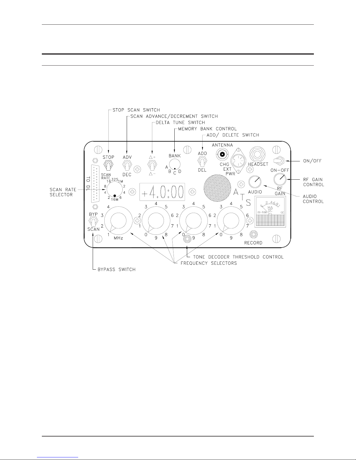
Refer to Figure 3 for the locations of the controls.
·
Add/Delete Switch
Use this switch to add or delete one frequency or all frequencies to the
memory.
·
Audio Control
Controls the audio level of the speaker or headset. Maximum audio level
occurs with this control positioned fully clockwise.
The audio control acts as a switch to turn the tone decoder on and off. When
the audio control is off, the tone decoder is activated. The plus sign on the left
Receiver Manual R01-02-A Advanced Telemetry Systems, Inc.
Figure 3 - Receiver Controls for Model R4000
Page 12

side of the frequency display then indicates signal presence. The plus sign is
normally on while the audio is on.
Bypass Switch
·
Transfers control of receiver frequency selection from the memory to the
frequency selectors or vice versa. If this switch is in the bypass position, the
user can manually tune the frequency using the frequency selectors. If this
switch is in the scan position, the receiver will begin scanning through the
frequencies programmed in the receiver’s memory.
Delta Tune Switch
·
Use this switch to tune the receiver’s frequency up or down by 4 kHz.
· Frequency Selectors
page 9
Use the four frequency selector knobs to tune the desired frequency. The
frequency can be selected in 1 kHz increments over a 4 MHz range. The
megahertz switch (the left-most knob) selects one of the four megahertz
ranges.
· Memory Bank Selector
Use this dial to select which memory bank to use.
·
On/Off Switch
Use this switch to turn the receiver on or off.
·
RF Gain Control
This control varies the gain of the intermediate frequency (IF) amplifiers.
Maximum gain occurs with the control positioned fully clockwise. The
sensitivity of the receiver is set with this control.
·
Scan Advance/Decrement Switch
Allows you to rapidly move through the frequencies programmed in
memory; moving forward or backward through the frequencies in numerical
order. This switch overrides the scan rate and stop scan switches.
Advanced Telemetry Systems, Inc. R01-02-A Receiver Manual
Page 13

page 10
Scan Rate Selector
·
Adjusts the length of time the receiver will monitor a frequency programmed
in the receiver’s memory. This control is effective only when the bypass
switch is in the center or bypass position. A range of 2 seconds to 16 minutes
is available.
Stop Scan Switch
·
Stops the memory scan from advancing to the next frequency when placed in
the upper position. The receiver will remain on the current frequency until
the switch is lowered.
Tone Decoder Threshold Control
·
To control the threshold of the tone decoder, turn the control clockwise to
increase sensitivity (reduce the threshold level) or counterclockwise to
decrease sensitivity (increase the threshold level).
Receiver Manual R01-02-A Advanced Telemetry Systems, Inc.
Page 14
RECEIVER INDICATORS
page 11
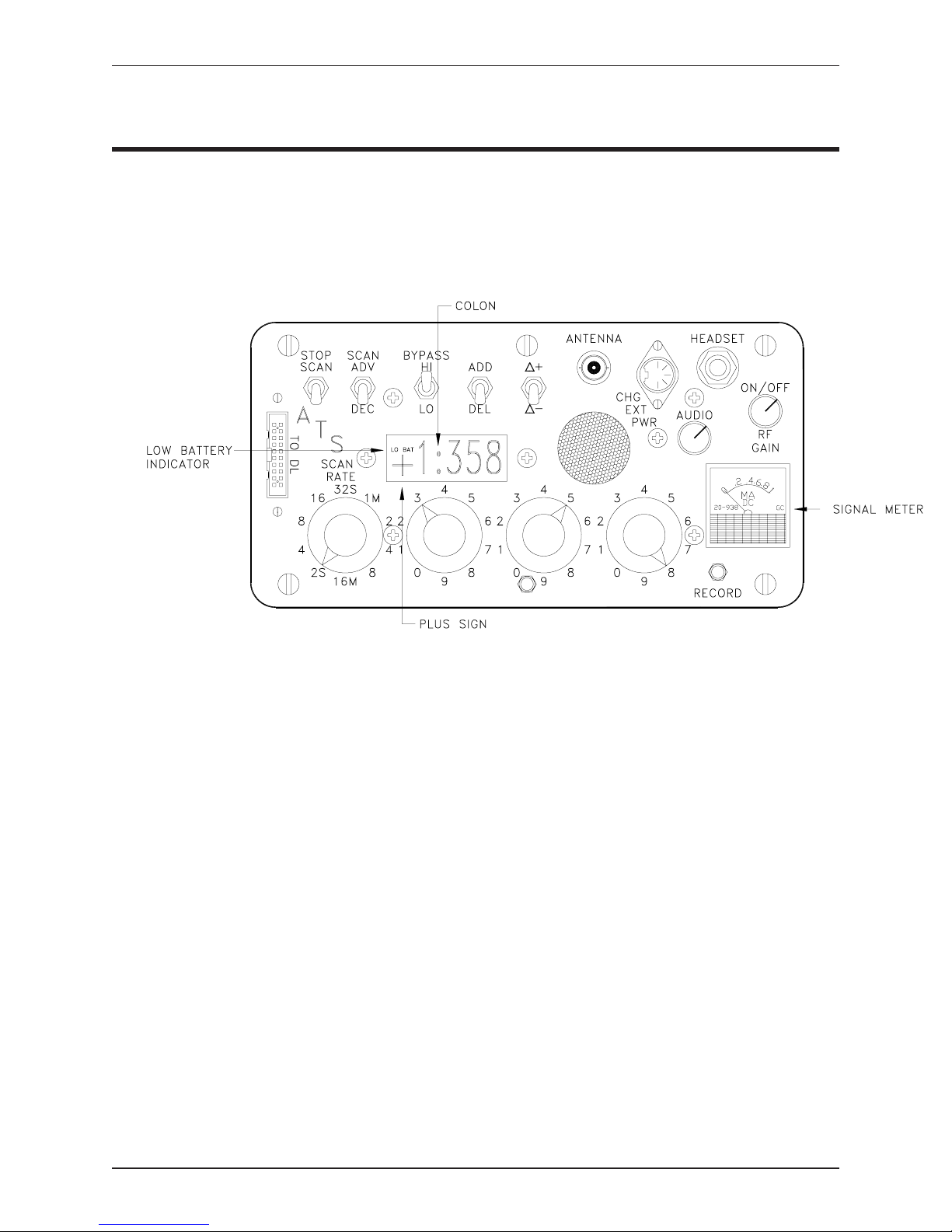
Figure 4 - Receiver Indicators
There are a number of indicators that show the status of the receiver, see Figure 4.
·
Low Battery Indicator
When the receiver’s internal batteries are low and need recharging, thewords
“LO BAT” flash on the receiver’s display to the left of the frequency. See the
section on POWER CONSIDERATIONS for directions on charging the
receiver’s batteries.
·
Plus Sign
On the receiver’s display to the left of the frequency, there may appear a plus
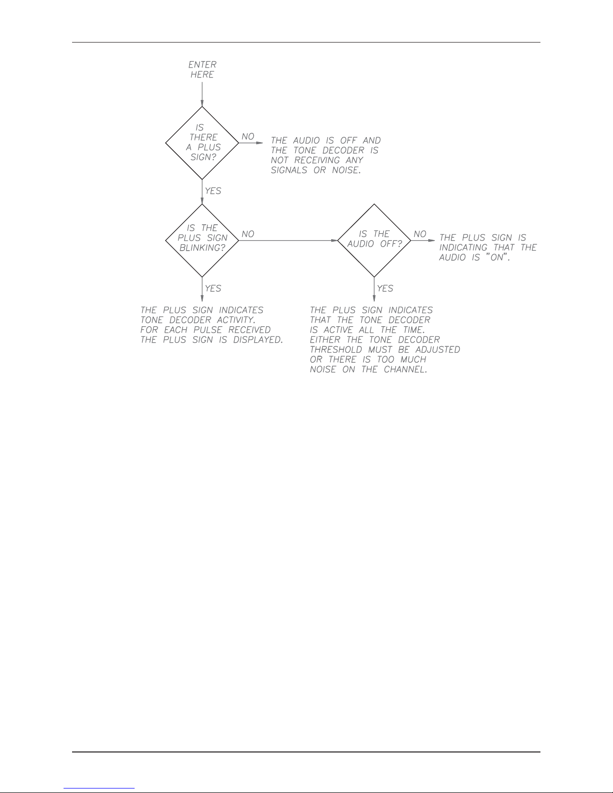
sign. To learn about what this plus sign means, follow the flowchart in Figure
5.
Advanced Telemetry Systems, Inc. R01-02-A Receiver Manual
Page 15
page 12
Figure 5 - Explanation of Plus Sign Indicator
·
Signal Meter
The signal meter indicates the strength of the audio signal on the receiver’s
channel. It can be used as an indicator of signal strength in direction finding
or as an indication of activity (if the activity behavior modifies the signal
amplitude). Also, it integrates the signal level to make the meter less
responsive to noise and to keep the meter needle from bouncing on pulsing
transmitters. The meter level can be offset by an internalcontrol adjustment.
·
Stored Frequency Indicator
When a colon is present on the receiver’s display, it means that the frequency
displayed is stored in the receiver’s memory.
Receiver Manual R01-02-A Advanced Telemetry Systems, Inc.
Page 16

PROGRAMMING THE RECEIVER
This section covers the steps to program the receiver’s memory and scan rate.
To Add a Frequency to Memory
Models R2000 and R2100
1. Set the bypass switch in the HI or LO position.
2. Select the desired frequency with the frequency selectors.
3. Push the add/delete switch upward.
page 13
4. Watch to see that a colon appears between the hundredths digit and tenths digit.
The colon signifies that the frequency has been added to the memory. If a
colon was present when the frequency was selected, the frequency was
already in the memory.
Model R4000
1. Set the memory bank selector to choose which of the four memory banks to use.
Each memory bank is independent. A frequency may be added to one or all
banks.
2. Put the bypass switch in the bypass position.
3. Select the desired frequency with the frequency selectors.
4. Push the add/delete switch upward.
5. Watch to see that a colon appears between the hundredths digit and tenths digit.
The colon signifies that the frequency has been added to the memory. If a
colon was present when the frequency was selected, the frequency was
already in the memory.
Advanced Telemetry Systems, Inc. R01-02-A Receiver Manual
Page 17

page 14
To Delete a Frequency from Memory
Models R2000 and R2100
1. Set the bypass switch in the HI or LO position.
2. Select the desired frequency with the frequency selectors.
3. Push the add/delete switch downward.
4. Watch to see that the colon disappears between the hundredths digit and tenths digit.
Model R4000
1. Set the memory bank selector to chose which memory bank to use.
2. Put the bypass switch in the bypass position.
3. Select the desired frequency with the frequency selectors.
4. Push the add/delete switch downward.
5. Watch to see that the colon disappears between the hundredths and tenths digits.
To Program All Frequencies into the Memory
Models R2000 and R2100
1. Set the bypass switch in the middle position.
2. Hold the add/delete switch upward for approximately 4 seconds.
After approximately 4 seconds, the receiver will start to scan, adding all the frequencies
to the memory. If using a 150-151.999 MHz receiver, this would program every
frequency from 150.000 to 151.999 MHz in 1 kHz increments into the memory.
Receiver Manual R01-02-A Advanced Telemetry Systems, Inc.
Page 18

Model R4000
1. Set the bypass switch in the scan position.
2. Hold the add/delete switch upward for approximately 4 seconds.
After approximately 4 seconds, the receiver will start to scan, adding all the
frequencies into the memory. If using a 150-153.999 MHz receiver, this
would program every frequency from 150.000 to 153.999 MHz in 1 kHz
increments into the memory.
To Delete All Frequencies from Memory
Models R2000 and R2100
page 15
1. Set the bypass switch in the middle position.
2. Hold the add/delete switch downward for approximately 4 seconds.
After approximately 4 seconds, the receiver will start to scan, deleting all the
frequencies stored in the memory.
Model R4000
1. Set the bypass switch in the scan position.
2. Hold the add/delete switch downward for approximately 4 seconds.
After approximately 4 seconds, the receiver will start to scan, deleting all the
frequencies stored in the memory.
To Choose the Scan Rate
The scan rate selector controls how long the receiver remains tuned to each programmed
frequency in the memory mode of operation. Scan rate is adjustable from 2 seconds to
16 minutes.
Advanced Telemetry Systems, Inc. R01-02-A Receiver Manual
Page 19

page 16
SCANNING FREQUENCIES STORED IN MEMORY
This section explains how to scan through the frequencies you have programmed in the
receiver’s memory.
To Start Scanning
Model R2000 and R2100
Place the bypass switch in the middle position to start the receiver scanning through the
frequencies programmed in the receiver’s memory.
Model R4000
Place the bypass switch in the scan position to start the receiver scanning through the
frequencies programmed in the receiver’s memory.
To Delete a Frequency from Memory while Scanning
1. Wait until the receiver stops on the frequency you wish to delete.
2. Push the add/delete switch downward.
3. Watch to see that the frequency disappears and the next frequency is displayed.
Deleting frequencies from the scanning cycle as the transmitters are found saves time,
especially during aerial searches.
To Rapidly Move through Frequencies Programmed in Memory
The scan advance/decrement switch is used to skip over programmed frequencies at a
fast rate. The memory advances or decrements in numerical order. Advance skips to the
next higher frequency; decrement skips to the next lower frequency. The decrement
feature is useful when a transmitter is heard at the end of the scan interval and the
memory advanced to the next frequency before the stop scan switch could be activated.
The scan advance/decrement switch overrides the scan interval set by the scan rate
selector.
Receiver Manual R01-02-A Advanced Telemetry Systems, Inc.
Page 20

page 17
To Stop Scanning
The stop scan switch stops the memory scan indefinitely. When you want to stay on a
programmed frequency, simply place this switch in the upper position. Place the switch
in the lower position to resume scanning. The stop scan switch is useful when a signal is
heard while searching for a number of animals and detailed information is needed as to
where the animal is located.
RECEIVER OPERATIONS
This section explains how to use the receiver in audio mode. When you are using the
receiver without an external recording device, you will want to use the receiver in the
audio mode. The receiver’s tone decoder is for use with an external recording device
such as a Data Collection Computer (DCC).
1. Turn the ON/OFF RF Gain control fully clockwise.
The ON/OFF switch controls the power to the receiver whether the receiver
is operating on its own internal batteries or an external power source (11.5 15VDC).
With the RF Gain control positioned fully clockwise, the receiver operates at
maximum gain to achieve maximum sensitivity.
2. Set the audio control at a comfortable noise levelon thespeaker orin theheadset.
The audio level does not affect the signal to noise ratio or sensitivity except
for its effect on hearing sensitivity. It does, however, affect the signal meter
indication.
3. Select a frequency.
Models R2000 and R2100
With the bypass switch in the middle position, the memory controls the
frequency. With the bypass switch in the HI or LO position, the memory is
disabled and the frequency selectors control the frequency. The frequency
can be tuned in 1 kHz increments over a 1 MHz range. The LO and HI
positions determine if the receiver is using the low or high frequency band.
For example, using a 150-151.999 MHz receiver with the bypass switch in
the LO position, the receiver would be in the 150-150.999 MHz range. With
Advanced Telemetry Systems, Inc. R01-02-A Receiver Manual
Page 21

page 18
the bypass switch in the HI position (again using a 150-151.999 MHz
receiver), the receiver would be in the 151-151.999 MHz range. A “1"
appears before the frequency indicating the high band.
Model R4000
With the bypass switch pointing to scan, the memory controls the frequency.
With the bypass switch pointing to bypass, the frequency selectors control
the frequency. The four frequency selectors let you tune in 1 kHz increments
over a 4 MHz range.
4. Find the signal.
The delta tune switch allows you to check one IF bandwidth (± 4 kHz) on
each side of the frequency without changing the frequency selectors. Use this
switch if no signal is heard on the programmed frequency. Simply hold the
switch in the desired position. The frequency display will not change when
this switch is activated. The delta tune switch can be activated in both the
bypass and memory modes. The delta tune switch is useful if it becomes
necessary to retune the least significant digit of the frequency to compensate
for frequency drift. It reduces the number of frequencies you would need to
program if you had to check on both sides of the original transmitter
frequency.
5. Reduce the RF gain by turning the RF gain control counter-clockwise.
Once the signal is found, the RF gain should be reduced to achieve a signal
level where differences in signal amplitudes can easily be detected. The RF
gain should also be reduced as you move toward a signal source to prevent
overload of the receiver.
Although overload causes no damage, it can be confusing since it causes spurious
signals to be generated. Overload (spurious signals) can result in signals appearing on
frequencies where no signal sources are supposed to be. This problem usually does not
occur during normal operations. However, there are two circumstances where this
might occur.
·
Placing the transmitter too close to the receiver.
If you are bench testing your transmitters and receiver, and they are close
together, you can get receiver overload. To correct this problem, make sure
the receiver is not connected to an antenna and turn the RF gain down as
needed.
Receiver Manual R01-02-A Advanced Telemetry Systems, Inc.
Page 22

page 19
Moving in on the transmitter’s location.
·
As you move toward the transmitter’s signal, you will have to turn down the
RF gain to avoid overload. Also, verify that you are correctly tuned in on the
transmitter’s frequency.
Setting the RF gain control is the most critical for accurate and efficient signal source
detection.
INTERPRETING THE DATA
Standard transmitters pulse on and off at a constant rate. Many of the standard
transmitters use a rate of 60 pulses per minute (ppm). That is one pulse per second.
If you stay on a channel counting pulses for 10 seconds you should see (or hear)
approximately 10 pulses during that time. You may see 8, 9, or 10 pulses if the
transmitter is within range but what if you see 5 pulses, what does that mean? In that
case, it could be a number of possibilities. It could mean there is no transmitter there at
all, only noise. Although, if it was noise, it would not be pulsing on and off at a constant
rate. It could also be a transmitter on the edge of the reception range or a transmitter
which is not properly tuned in.
To avoid as many of these problems as possible, you should thoroughly field test the
system. You will need to check for noisy channels. Tune your transmitters according to
the directions in APPENDIX B. Also, learn how to correctly adjust the tone decoder
threshold control on the receiver.
POWER CONSIDERATIONS
The receiver’s internal Nicad batteries should be recharged approximately 1.5 hours for
every 1 hour of use. Do not leave the charger on indefinitely because damage to the cells
may occur.
NOTE: Only use the battery charger to recharge the receiver’s internal
batteries. Do not use the battery charger to power the receiver from an AC
outlet. No harm will be done if you try this. However, using the battery charger
in this way may not provide sufficient power over time and may also contribute
noise. If you need to power the receiver from an AC outlet, you can purchase an
AC adapter from ATS.
Advanced Telemetry Systems, Inc. R01-02-A Receiver Manual
Page 23

page 20
When the battery voltage is low (whether using the internal batteries or an external
power source), the low battery indicator will flash on the frequency display. There is
approximately 1 hour of battery life remaining at this time if you are using the internal
batteries.
The memory is kept alive when the receiver is shut off by a small internal power source.
This source should last at least five years.
MAINTENANCE
We designed the receiver to be trouble-free for extended periods of use. To help
maintain its trouble-free status, we suggest the following:
1. Avoid extremes of temperature and humidity whenever possible. Storing the receiver
on a vehicle dashboard in full sunlight will age the batteries and components faster.
2. Avoid placing the receiver or its antenna near high-powered radio transmissions such
as CB radio transceivers. These can cause damage to the receiver.
3. Avoid dust and sand, whenever possible. Keep thereceiver inits paddednylon case as
much as possible. Although the switches have gaskets, some grit may enter causing the
switches to wear out faster.
4. Check your receiver’s batteries as follows:
a. Fully charge the batteries by leaving the charger in overnight.
b. Turn the receiver on.
c. Watch to see that the receiver operates for six hours before the low battery
indicator begins to flash.
5. Keep the batteries charged during storage periods. Every 60-90 days, turn the receiver
on for 4-6 hours until the low battery indicator comes on. Then, recharge the batteries
and store the receiver.
6. Check the receiver’s sensitivity by performing a range test in the field. In most cases,
a malfunction causes a drastic reduction in range.
7. Service the receiver at our factory or one of our service centers.
Receiver Manual R01-02-A Advanced Telemetry Systems, Inc.
Page 24

page 21
APPENDIX A - WARRANTY
Advanced Telemetry Systems (ATS) warranties its receivers for a period of one year
from the date of shipment. During the warranty period, ATS will repair or replace, at its
option, any defective receivers.
Defective products must be returned to ATS in Isanti, Minnesota or to a designated
service center for warranty service. The buyer shall prepay shipping charges to ATS;
ATS will pay return shipping costs.
For service, return equipment to ATS. Please give a description of the services required
on your equipment. For repairs, describe in detail any problems you are having,
especially if problems are intermittent. Please visit our website at www.atstrack.com to
obtain a repair form. If you are returning equipment from an international country, it is
helpful to put the Tariff code of 9801.00.12 (Articles returned temporarily for repair) on
your custom forms.
Limitations: Warranty does not apply to defects resulting from improper maintenance
or use, physical damage, or operation outside environmental specifications.
No other warranties are expressed or implied. ATS specifically disclaims any
implied warranties of merchantability and fitness for a particular use.
The remedies listed under this warranty are the buyers sole and exclusive remedy.
ATS shall not be liable for any direct, indirect, special, incidental or consequential
damages.
Advanced Telemetry Systems, Inc. R01-02-A Receiver Manual
Page 25

page 22
APPENDIX B - PROCEDURE FOR TUNING TRANSMITTERS
During the tuning process, the transmitter’s temperature should be equivalent to the
expected field temperature. Ideally, the final tuning should be done at the field site.
1. Place the transmitters 100 to 200 meters away from the receiving antenna.
2. Connect the receiving antenna to the receiver.
3. Turn the audio control on and turn the RF gain control to maximum.
4. Use the frequency selectors to tune in the transmitter’s frequency.
5. Find the frequency range that the transmitter’s signal comes in at (the range should be
3-5 kHz wide).
You many need to reduce theRF gainto keep the receiver from overloading.
6. The center frequency of this frequency range is the frequency you should use.
Note: For tuning transmitters for use with a DCC, see your DCC manual.
Receiver Manual R01-02-A Advanced Telemetry Systems, Inc.
Page 26

page 23
APPENDIX C - ADJUSTING THE THRESHOLD CONTROL
Models R2100 and R4000
You need to adjust the tone decoder threshold control if conditions are extremely
noisy or extremely quiet.
1. Connect an antenna to the receiver.
2. Select a frequency where no valid signals are present.
Verify this by turning on the audio and if no pulses are heard, there are no
valid signals present.
3. Turn the audio off.
4. Using a small flat screwdriver, turn the tone decoder threshold control clockwise
until the “+” sign on the frequency display flashes.
The tone decoder is now triggering on noise.
5. Turn the tone decoder threshold control back (counter clockwise) until the “+”
sign disappears.
Advanced Telemetry Systems, Inc. R01-02-A Receiver Manual
Page 27

page 24
APPENDIX D - QUESTIONS ??
If you havequestions concerning your ATS receiver, callAdvanced Telemetry Systems
(ATS) at (763) 444-9267 or email [email protected]. You may also visit our website
at www.atstrack.com.
Receiver Manual R01-02-A Advanced Telemetry Systems, Inc.
Page 28
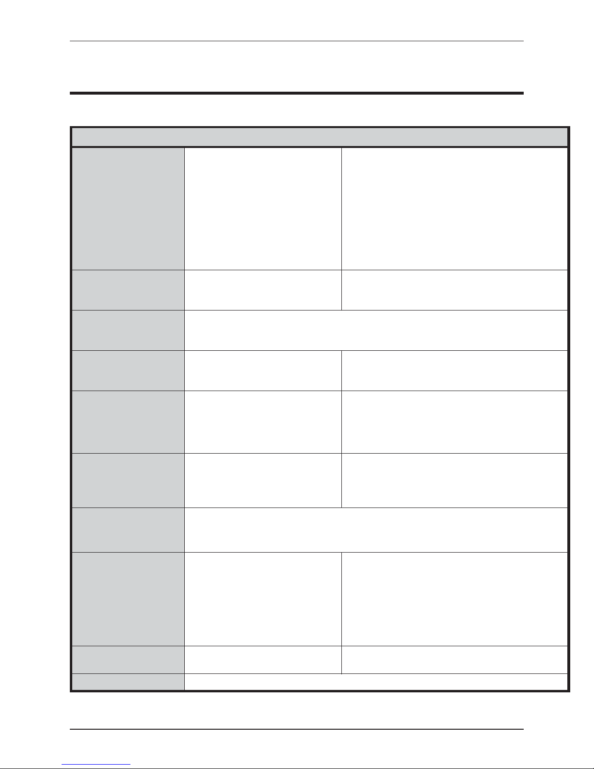
RECEIVER SPECIFICATIONS FOR MODELS R2000 AND R2100
GENERAL
CONTROLS
MEMORY
DISPLAYS
CONNECTIONS
POWER
COMPUTER
INTERFACE
(Model R2100 only)
PHYSICAL
page 25
APPENDIX E - RECEIVER SPECIFICATIONS
Frequency range:
Channel spacing:
Input impedance:
Minimum discernable signal (MDS):
Noise figure:
Speaker:
Tone decoder detection range:
Tone decoder detection level:
Frequency stability:
Delta tune:
IF frequency:
IF bandwidth:
Image rejection:
RF gain control range:
Operating voltage range:
Dwell time:
Frequency selectors (three)
Audio level
RF gain
Delta Tune
Add/Delete to memory
All frequencies programmable
Sequentially scanned
Delete frequencies individually with single switch while scanning or in bypass mode
Delete all frequencies
Battery backed
Selected frequency:
Memory status:
Battery status:
Signal detection (Model R2100 only):
Signal level:
Antenna:
Headset:
External Power/Recharge Receptacle:
Signal Level: 0.125" Phone Jack Receptacle For External 0-1 mA
Computer Interface: (Model R2100 only) 20 Pin Ribbon Cable (pins on receiver connector requires
12 volts DC nominal, 130 mA drain nominal
Internal: 1.2 Amp-hour Nickel Cadmium Battery Pack
External: 9 to 18 Volts DC, Negative Ground
4 Digits BCD (active high)
Computer Control Select
5 Volt DC Regulated (5mA max)
Ground
Tone Decoder Output (active low)
Size: 4.3" wide x 8.3" long x 7" high
Weight: 5 lbs (2.3 kg)
Any specified 2 MHz range from 30 to 220 MHz
1 kHz
50 ohms
-150 dBm (0.007 uv into 50 ohms)
3 dB maximum
8 ohms
± 2 kHz (Model R2100 only)
-120 dBm minimum (Model R2100 only)
± 1 kHz -20 °Cto+50°C
+ 4 kHz; -4 kHz
10.7 MHz
6dB± 2 kHz, 80 dB ± 7 kHz
>150 dB
>150 dB
9 to 18 volts DC
Selectable 2 seconds to 16 minutes (10 positions)
Auto scan/memory bypass
Increment frequency up/down
Dwell time (scan rate)
Receiver on/off
Tone decoder threshold (Model R2100 only)
LCD (0.5" H digits) with backlight for night use
Colon in display indicates frequency stored in memory
Lo Bat flashes when battery voltage is low
+ present in display indicates detection by tone decoder
0-1 mA meter
BNC - female
Receptacle for .250" phone plug
5 pin DIN
100 ohm Current Meter
socket on cable)
8 Hour Nominal Operating Time
Switches Automatically to External Power When Present
(11 cm x 21 cm x 18 cm high)
Accessories (included): External Power Cord
Accessories (optional): David Clark Aviation Grade Headset
ENVIRONMENTAL
WARRANTY
Advanced Telemetry Systems, Inc. R01-02-A Receiver Manual
Operating Temperature:
Storage Temperature:
Humidity:
One year parts and labor on materials and workmanship.
Battery Charger
Padded Nylon Case
Telex Aviation Grade Headset (Model R2100 only)
Instruction Manual
-20 °Cto+50°C
-70 °Cto+50°C
95% Non-condensing
Page 29
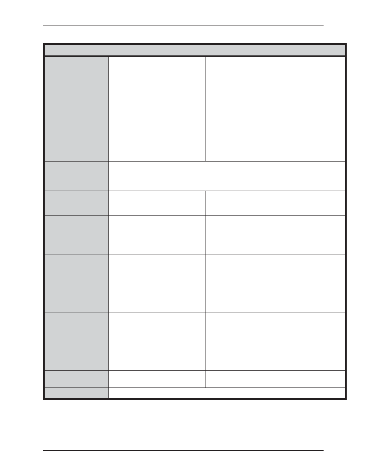
page 26
RECEIVER SPECIFICATIONS FOR MODEL R4000
GENERAL
CONTROLS
MEMORY
DISPLAYS
CONNECTIONS
POWER
COMPUTER
INTERFACE
PHYSICAL
Frequency range:
Channel spacing:
Input impedance:
Minimum discernable signal (MDS):
Noise figure:
Speaker:
Tone decoder detection range:
Tone decoder detection level:
Frequency stability:
Delta tune:
IF frequency:
IF bandwidth:
Image rejection:
RF gain control range:
Operating voltage range:
Dwell time:
Frequency selectors (four)
Audio level
RF gain
Delta Tune
Add/Delete to memory
Auto scan/memory bypass
Four distinct banks
All frequencies programmable in each bank
Sequentially scanned
Delete frequencies individually with single switch while scanning or in bypass mode
Delete all frequencies in a bank
Battery backed
Selected frequency:
Memory status:
Battery status:
Signal detection:
Signal level:
Antenna:
Headset:
External Power/Recharge Receptacle:
Signal Level: 0.125" Phone Jack Receptacle For External 0-1 mA
Computer Interface: 20 Pin Ribbon Cable (pins on receiver connector requires
12 volts DC nominal, 130 mA drain nominal
Internal: 1.2 Amp-hour Nickel Cadmium Battery Pack
External: 9 to 18 Volts DC, Negative Ground
4 Digits BCD (active high)
Computer Control Select
5 Volt DC Regulated (5mA max)
Ground
Tone Decoder Output (active low)
Size: 4.3" wide x 8.3" long x 7" high
Weight: 5 lbs (2.3 kg)
Any specified 4 MHz range from 147 to 220 MHz
1 kHz
50 ohms
-150 dBm (0.007 uv into 50 ohms)
3 dB maximum
8 ohms
± 2 kHz
-120 dBm minimum
± 1 kHz -20 °Cto+50°C
+ 4 kHz; -4 kHz
10.7 MHz
6dB± 2 kHz, 80 dB ± 7 kHz
>150 dB
>150 dB
9 to 18 volts DC
Selectable 2 seconds to 16 minutes (10 positions)
Increment frequency up/down
Memory bank select
Dwell time (scan rate)
Receiver on/off
Tone decoder threshold
LCD (0.5" H digits) with backlight for night use
Colon in display indicates frequency stored in memory
Lo Bat flashes when battery voltage is low
+ present in display indicates detection by tone decoder
0-1 mA meter
BNC - female
Receptacle for .250" phone plug
5 pin DIN
100 ohm Current Meter
socket on cable)
8 Hour Nominal Operating Time
Switches Automatically to External Power When Present
(11 cm x 21 cm x 18 cm high)
Accessories (included): External Power Cord
Accessories (optional): David Clark Aviation Grade Headset
ENVIRONMENTAL
WARRANTY
Receiver Manual R01-02-A Advanced Telemetry Systems, Inc.
Operating Temperature:
Storage Temperature:
Humidity:
One year parts and labor on materials and work
manship.
Battery Charger
Padded Nylon Case
Telex Aviation Grade Headset
Instruction Manual
-20 °Cto+50°C
-70 °Cto+50°C
95% Non-condensing
-
 Loading...