

Page 1
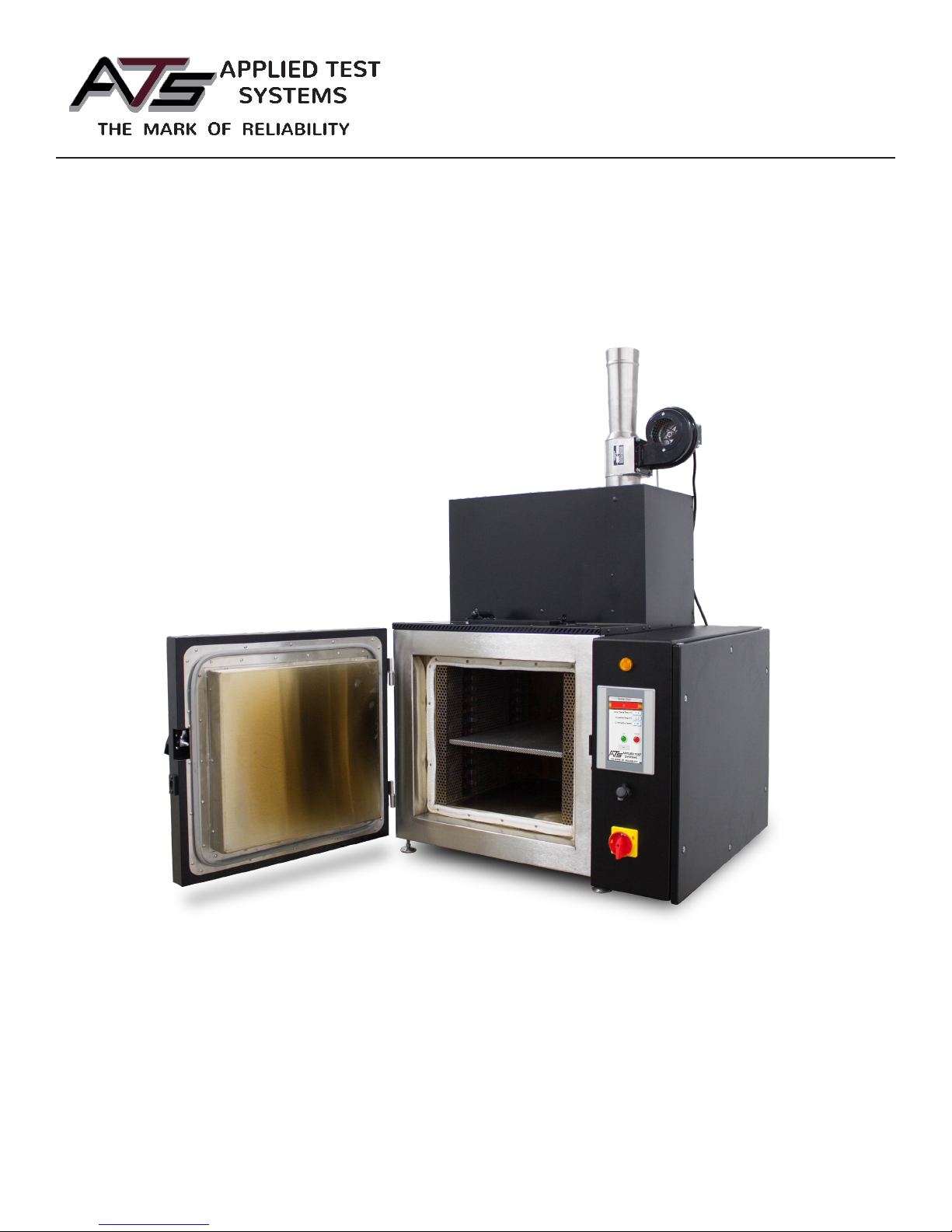
Pyrolytic Oven
INSTRUCTION MANUAL
This manual contains important operating and safety information. Carefully read and understand the
contents of this manual prior to the operation of this equipment.
MAN - Pyrolytic Oven - REV: Original
www.atspa.com
Page 2

REVISED AUGUST 2018
Information in this document is subject to change without notice and does not represent a commitment on the part of
Applied Test Systems (ATS).
© Copyright Applied Test Systems 2018
For assistance with set-up or operation, contact the ATS service department. Please have this manual and product serial
number available when you call.
Telephone: +1-724-283-1212.
MAN - Pyrolytic Oven - REV: Original
Page 3

Manual Contents
A. Introduction ................................................................................................................................ 1
A.1 Unpacking ........................................................................................................................................................... 1
A.2 Warranty Information .......................................................................................................................................... 1
A.3 After Sale Support .............................................................................................................................................. 1
A.4 Declaration of Conformity ................................................................................................................................... 2
B. Safety .......................................................................................................................................... 3
B.1 For Owners, Operators, and Maintenance ......................................................................................................... 3
B.2 Safety Instructions .............................................................................................................................................. 3
B.3 Warnings ............................................................................................................................................................. 3
C. System Overview ....................................................................................................................... 6
C.1 Equipment Parts ................................................................................................................................................. 6
Front of Unit ................................................................................................................................................. 6
Back of Unit .................................................................................................................................................. 7
C.2 General Overview ............................................................................................................................................... 8
Use ............................................................................................................................................................... 8
How it Works ................................................................................................................................................ 8
Parts That Can Be Cleaned ......................................................................................................................... 8
Organic Residues That Can Be Cleaned ..................................................................................................... 9
Organics Which Should Not be Processed .................................................................................................. 9
Automatic Cleaning Cycle ........................................................................................................................... 9
Limitations .................................................................................................................................................. 10
Cost of Operation ....................................................................................................................................... 10
Training of Operators ................................................................................................................................ 10
C.3 Product Specications .......................................................................................................................................11
D. Installation ................................................................................................................................ 12
D.1 Installation Overview ........................................................................................................................................ 12
D.2 Receiving ......................................................................................................................................................... 12
D.3 Electrical Service .............................................................................................................................................. 13
D.4 Installing Unit with Tilt ....................................................................................................................................... 13
D.5 Location and Venting ........................................................................................................................................ 13
Venting to the Outdoors Through Wall or Roof .......................................................................................... 14
Venting to a Lab Hood or Other Negative Pressure Exhaust System ....................................................... 14
iMAN - Pyrolytic Oven - REV: Original
Page 4

D.6 How to Measure Oven Negative Pressure (Draft) ............................................................................................ 15
D.7 How to Adjust to Oven Draft ............................................................................................................................. 15
D.8 Pressure Switch for Draft Inducer Blower Motor .............................................................................................. 16
E. Software Overivew ................................................................................................................... 17
E.1 Software Screen Map ....................................................................................................................................... 17
E.2 Main Screen ..................................................................................................................................................... 18
Start Button ................................................................................................................................................ 18
End/Stop Button ......................................................................................................................................... 18
Alarm Button .............................................................................................................................................. 18
View Button ................................................................................................................................................ 18
State Status Indicator Bar .......................................................................................................................... 19
O State ..................................................................................................................................................... 19
Oxidizer Preheat ........................................................................................................................................ 19
Oven Soak ................................................................................................................................................. 20
Run Soak .................................................................................................................................................. 20
Cool Down ................................................................................................................................................. 20
Cycle Finished ........................................................................................................................................... 20
Delay Start ................................................................................................................................................. 20
E.3 View Screen...................................................................................................................................................... 21
ID................................................................................................................................................................ 21
Password ................................................................................................................................................... 21
Manual Button ............................................................................................................................................ 21
Passwords Button ...................................................................................................................................... 22
Standardize Button .................................................................................................................................... 22
Settings, Language, Data, and Alarm Butons ........................................................................................... 22
Done Button ............................................................................................................................................... 22
E.4 Language Screen ............................................................................................................................................. 22
E.5 Settings Screen ................................................................................................................................................ 23
Cycle Time ................................................................................................................................................. 23
IP Address .................................................................................................................................................. 23
Current Time .............................................................................................................................................. 23
Preheat Delay ............................................................................................................................................ 23
Done Button ............................................................................................................................................... 24
E.6 Manual Screen .................................................................................................................................... 24
Six Buttons Across Top of Screen .............................................................................................................. 24
Four Indicators on the Left Side ................................................................................................................. 24
Values on the Right Side ............................................................................................................................ 24
Set Point for Both Oven and Oxidizer Chamber ........................................................................................ 24
Current Draft .............................................................................................................................................. 25
ii MAN - Pyrolytic Oven - REV: Original
Page 5

Done Button ............................................................................................................................................... 25
F. Operation ................................................................................................................................... 26
F.1 Important Operation Notications ...................................................................................................................... 26
Warnings (Yellow) ...................................................................................................................................... 26
Alarms (Orange) ........................................................................................................................................ 26
Faults (Red) ............................................................................................................................................... 26
F.2 Initial Start-Up: Empty Load .............................................................................................................................. 26
F.3 Starting a Normal Load of Dirty Glasswear or Metal Parts ............................................................................... 27
Tips on Loading .......................................................................................................................................... 27
F.4 Cycle Times for Cleaning .................................................................................................................................. 28
F.5 Cool-Down Before Removing the Glasswear or Metal Parts ............................................................................ 28
F.6 Additional Operation Precautions ...................................................................................................................... 29
F.7 Operation Instructions ....................................................................................................................................... 29
G. Troubleshooting ....................................................................................................................... 31
G.1 Troubleshooting Electrical Problems ................................................................................................................ 31
G.2 Manual Operation to Check Electrical Operaton .............................................................................................. 31
H. Maintenance ............................................................................................................................. 32
H.1 Door Seals and Gaskets .................................................................................................................................. 32
H.2 Cleaning the Oven Trays .................................................................................................................................. 32
H.3 Removal of Ashes and Pigments ..................................................................................................................... 32
H.4 Periodic Empty Tests & “Self-Cleaning” Cycles ................................................................................................ 32
H.5 Cleaning of Draft Inducer Fan .......................................................................................................................... 32
H.6 Replacement of Parts ....................................................................................................................................... 33
Every Six Months ....................................................................................................................................... 33
Every Twelve Months ................................................................................................................................. 34
H.7 Spare Parts List ................................................................................................................................................ 34
H.8 New HMI Software ........................................................................................................................................... 35
Appendix A: Warranty .................................................................................................................. 37
Appendix B: Wiring Diagrams ..................................................................................................... 38
Appendix C: Image Glossary....................................................................................................... 44
iiiMAN - Pyrolytic Oven - REV: Original
Page 6
A. Introduction
A.1 Unpacking
Retain all cartons and packing materials until the unit is operated and found to be in good condition. If damage has
occurred during shipping, notify Applied Test Systems (ATS) and the carrier immediately. If it is necessary to le a
damage claim, retain the packing materials for inspection by the carrier.
A.2 Warranty Information
All new ATS systems are shipped with a warranty. Units have a warranty against defective parts and workmanship
for one full year from the date of shipment. Please see APPENDIX A of this manual for complete details on the
warranty.
A.3 After Sale Support
If there are any questions concerning the operation of the unit or software, contact the ATS Service Department at
+1-724-283-1212.
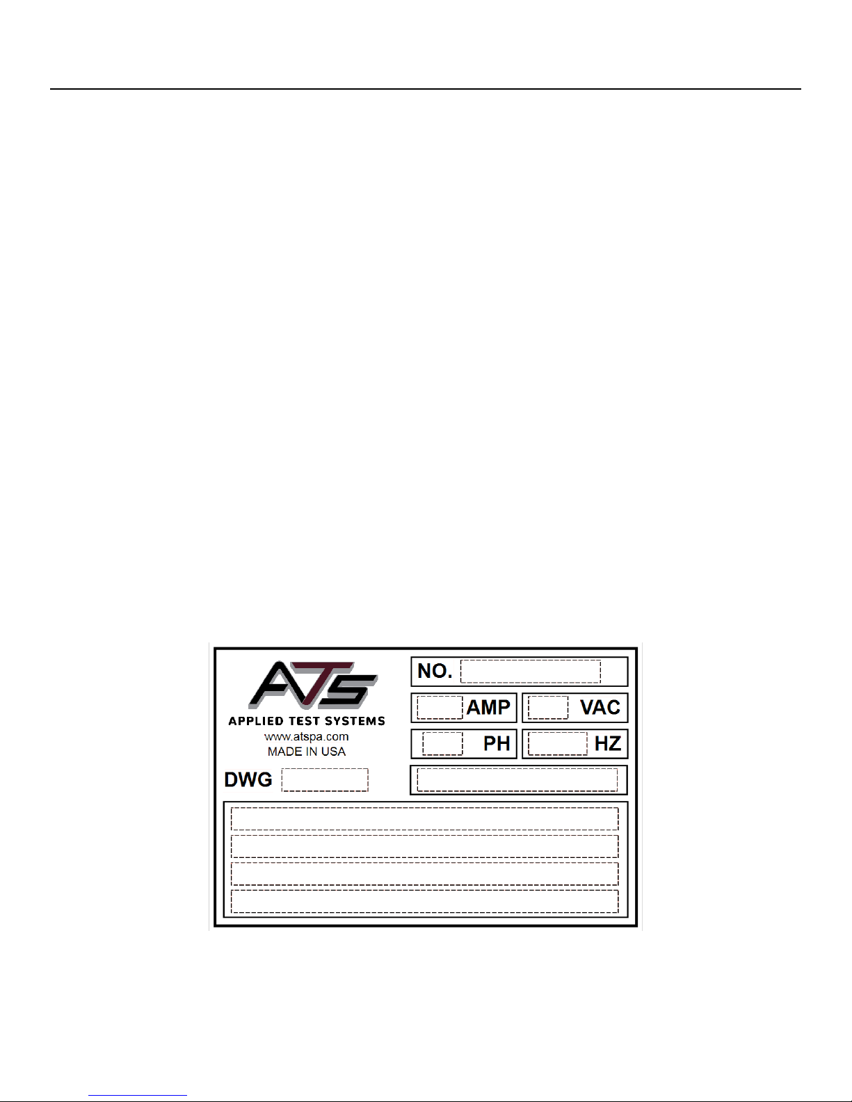
Before calling, please obtain the software revision number and the serial number from the unit’s data tag. A sample
data tag is illustrated below, and can be completed with the unit’s information for easy reference. Please be
prepared to give a complete description of the problem to the ATS Service Department.
MAN - Pyrolytic Oven - REV: Original | A. Introduction 1
Figure A.1: ATS Sample Data Tag
Page 7

A.4 Declaration of Conformity
We hereby declare under our sole responsibility that this product conforms to the technical requirements of the
following standards:
EMC: EN 61000-3-2, EN 61000-3-3, EN 61326-1
Limits for harmonic current emissions (OV134510-33 only) Limits for voltage uctuations and icker (OV134510-33
only)
Electrical equipment for measurement, control, and laboratory use; Part I: Generic Requirements
Safety: EN 61010-1, EN 61010-2-010
Safety requirements for electrical equipment for measurement, control, and laboratory use; Part I: General
Requirements.
Part II: Particular requirements for laboratory equipment for the heating of materials per the provisions of the
Electromagnetic Compatibility Directive 89/336/EEC as amended by 92/31/EEC and 93/68/EEC, and per the
provisions of the Low Voltage Directive 73/23/EEC, as amended by 93/68/EEC.
Copies of the Declaration of Conformity are available upon request.
MAN - Pyrolytic Oven - REV: Original | A. Introduction2
Page 8

B. Safety
B.1 For Owners, Operators, and Maintenance
All ATS equipment is designed to be operated with the highest level of safety. This manual uses note, caution, and
warning symbols throughout to draw your attention to important operational and safety information.
Read and understand all instructions and safety precautions listed in this manual before installing or operating
your unit. If you have any questions regarding operation of the unit or instructions in this manual, contact the ATS
Service Department at +1-724-283-1212.
Read and follow these important instructions. Failure to observe these instructions can result in permanent damage
to the unit, signicant property damage, personal injury or death.
B.2 Safety Instructions
Your Pyrolytic Oven has been designed with function, reliability, and safety in mind. It is the user’s responsibility
to install it in conformance with local electrical codes. For safe operation, please pay attention to the alert boxes
throughout the manual.
WARNING: Warnings alert you to a possibility of personal injury.
CAUTION: Cautions alert you to a possibility of damage to the equipment.
NOTE: Notes alert you to pertinent facts and conditions.
HOT SURFACE: This symbol alerts you to a possibility of personal injury if you come in contact
with a surface during use or for a period of time after use.
ELECTRICAL SHOCK: This symbol alerts you to a possibility of personal injury due to live
electrical components which may be exposed inside of the cover or unit.
B.3 Warnings
The following statements are WARNING statements. Unlike CAUTION statements, WARNING statements alert the
operator to conditions that may injure personnel. Operators must be aware of these conditions in order to prevent
injuries that may occur while operating this equipment.
MAN - Pyrolytic Oven - REV: Original | B. Safety 3
Page 9

WARNING: To avoid electrical shock, this furnace must use a properly grounded electrical supply
of correct voltage and current handling capacity, and be disconnected from the power supply
prior to maintenance and servicing.
WARNING: To avoid personal injury do not use in Class I, II, or Ill locations as dened by the
National Electrical Code.
WARNING: Do not use in the presence of ammable or combustible materials; re or explosion
may result. This device contains components which may ignite such materials.
WARNING: Do not put sealed containers in oven.
WARNING: Refer servicing to qualied personnel.
WARNING: THIS PRODUCT CONTAINS REFRACTORY CERAMIC, REFRACTORY
CERAMIC FIBER OR FIBERGLASS (GLASS WOOL) INSULATION WHICH CAN PRODUCE
RESPIRABLE FIBERS AND DUST WHEN HANDLED. THESE FIBERS OR DUSTS CAN
CAUSE IRRITATION AND CAN AGGRAVATE PRE-EXISTING RES PIRATORY DISEASE.
REFRACTORY CERAM IC INSULATIONS MAY CONTAIN OR MAY FORM CRYSTALLINE
SILICA (CRYSTO BALITE) WHICH MAY CAUSE LUNG DAMAGE (SILICOSIS).
THE INTERNATIONAL AGENCY FOR RESEARCH ON CANCER (!ARC) HAS CLASSIFIED
REFRACTORY CERAMIC FIBER AND FIBERGLASS AS {28) POSSIBLY CARCINOGENIC.
!ARC HAS CLASSIFIED CRYSTALLINE SILICA AS (2A) PROBABLY CARCINOGENIC.
The insulating materials are located in the door, the hearth collar, in the chamber of the product
or the top plate assembly. Tests performed by the manufacturer indicate that there is no
signicant risk of exposure to dust or respirable bers resulting from operation of this equipment
under normal conditions. However, there may be a risk of exposure to respirable dusts or
bers when repairing or maintaining the insulating materials, or when otherwise disturbing the
materials in a manner which causes release of dust or bers therefrom. Through the use of
proper handling procedures you can work safely with these insulating materials and minimize
any exposure.
Accordingly, before you repair or replace any insulating materials, or perform any other servicing
on this product which could disturb or cause exposure to dust from insulating materials, you
should consult the appropriate Material Safety Data Sheets (MSDS’s) for such products with
respect to proper handling and appropriate protective equipment. For additional MSDS’s, or
additional information concerning the handling of refractory ceramic products, please contact the
ATS Service Department at +1-724-283-1212.
WARNING: This warning is presented for compliance with California Proposition 65 and other
regulatory agencies and only applies to the insulation in this product. This product contains
refractory ceramic, refractory ceramic ber or ber glass insulation, which can produce respirable
dust or bers during disassembly. Dust or bers can cause irritation and can aggravate preexisting respiratory diseases. Refractory ceramic and refractory ceramic bers (after reaching
1000°C) contain crystalline silica, which can cause lung damage (silicosis). The International
MAN - Pyrolytic Oven - REV: Original | B. Safety4
Page 10

Agency for Research on Cancer (IARC) has classied refractory ceramic ber and berglass as
possibly carcinogenic (Group 28), and crystalline silica as carcinogenic to humans (Group 1).
The insulating materials can be located in the door, the hearth collar, in the chamber of the
product or under the hot plate top.
Tests performed by the manufacturer indicate that there is no risk of exposure to dust or
respirable bers resulting from operation of this product under normal conditions. However, there
may be a risk of exposure to respirable dust or bers when repairing or maintaining the insulating
materials, or when otherwise disturbing them in a manner which causes release of dust or
bers. By using proper handling procedures and protective equipment you can work safely with
these insulating materials and minimize any exposure. Refer to the appropriate Material Safety
Data Sheets (MSDS) for information regarding proper handling and recommended protective
equipment. For additional MSDS copies, or additional information concerning the handling of
refractory ceramic products, please contact ATS Service Department at +1-724-283-1212.
MAN - Pyrolytic Oven - REV: Original | B. Safety 5
Page 11
C. System Overview
C.1 Equipment Parts
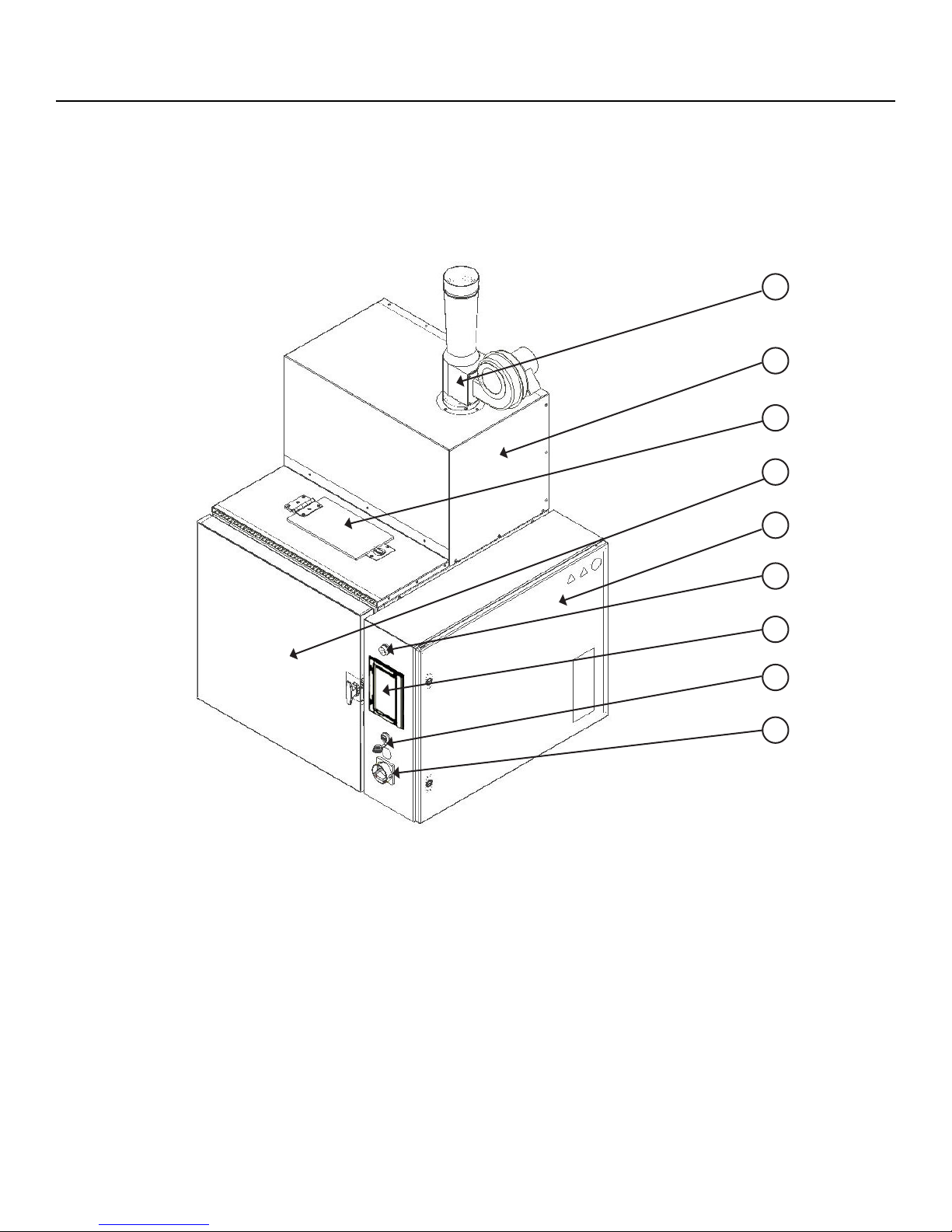
Front of Unit
1
2
3
4
5
1. Draft Inducer
2. Oxidizer Chamber
3. Blow-O Door
6
7
8
9
Figure C.1: Pyrolytic Oven Front
6. Power Light
7. HMI Touch Screen
8. USB Port
4. Oven Chamber
5. Electrical Box
6 MAN - Pyrolytic Oven - REV: Original | C. System Overview
9. Power Switch
Page 12
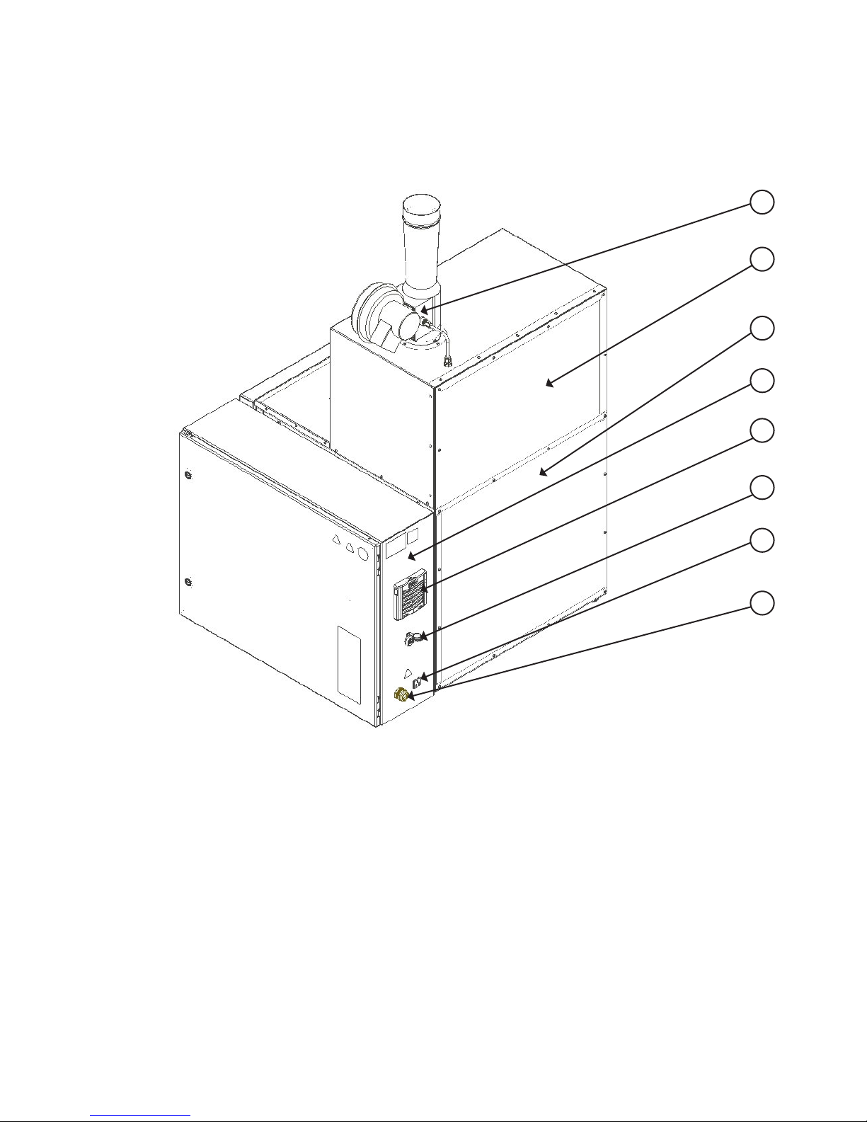
Back of Unit
1
2
3
4
5
6
Figure C.2: Pyrolytic Oven (Rear View)
1. Draft Inducer
2. Oxidizer Chamber
3. Oven Chamber
4. Electrical Control Box
7
8
5. Air Intake Filter
6. Ethernet Port
7. Draft Inducer Power Outlet
8. Power Cord
MAN - Pyrolytic Oven - REV: Original | C. System Overview 7
Page 13

C.2 General Overview
Use
The Pyrolytic Oven is designed to clean glass or metal parts contaminated with residues of various organic
substances such as polymers, waxes, resins, asphalts, tars, or other similar contaminants. Cleaning is done entirely
with heat, eliminating the use of solvent or chemical cleaning. Organic residues are thermally decomposed and
vaporized from glass or metal parts at 900 degrees F. Virtually all types of heat-resistant glass and metal parts can
be cleaned in the oven. As long as the heat will not hurt the parts being cleaned, and the residues to be removed
are organic and can be removed thermally, the Pyrolytic Oven is a suitable alternative to solvent and chemical
cleaning methods.
How it Works
1. Heat Decomposes and Vaporizes Organic Residues from the Glass or Metal Parts
The Pyrolytic Oven is a high-temperature oven capable of operating at 800-1000 degrees F. This temperature is
sucient to thermally decompose (vaporize) most polymeric residues and other organic material to volatile gases
and carbonized residues without harming the glass or metal parts. The pyrolysis smoke and gases produced by
degradation of the organic residues reacts with a catalyst suspended in stainless steel wire mesh which comprise of
two racks (trays) inside the oven chamber. If sucient smoke or pyrolysis gases are produced inside the oven, the
oxidation of this smoke will consume oxygen inside the oven and actually inert the oven to a very low oxygen level of
one to two percent.
2. Pyrolysis Smoke and Gases are consumed by Electric/Catalytic Oxidizer (Afterburner)
Any un-reacted pyrolysis products formed inside the oven exit through a pipe at the top of the oven and passes
through a small Oxidizer chamber which sits on top of the oven. The Oxidizer is a combination electric/catalytic
system which preheats the oven exhaust gases to 1300-1500 degrees F with excess air before they pass through a
honeycomb ceramic catalyst which completes any oxidation not occurring in the preheat zone of the chamber. This
pollution control method is very eective at destroying any smoke and odor produced during the cleaning process.
The exhaust gases from the oxidizer chamber are mixed with fresh air, resulting in a pollution-free exhaust at
temperatures of 130-160 degrees F.
3. Final Cleaning is accomplished by the Oxidation Stage.
The heat-cleaning process actually consists of two distinct stages. The rst stage is the pyrolysis stage described
above. The second stage consists of oxidation of any carbonized residues produced during the rst, pyrolysis stage.
Virtually all organic materials produce some soot-like, carbon residues on thermal decomposition. Injecting air into
the 950 degree F oven chamber during the nal cleaning stage oxidizes carbon residues, leaving the glassware or
metal parts completely free of any organic matter. Ash or other inorganic material is left behind) on the parts and
can be washed o with water.
Parts That Can Be Cleaned
Any part which the normal cleaning temperature of 800-950°F will not hurt can be cleaned in the oven. Laboratory
glassware, particularly the heat resistant types are easily cleaned without damage or distortion. Ceramic parts
which can tolerate the heat can also be cleaned.
8 MAN - Pyrolytic Oven - REV: Original | C. System Overview
Page 14

Organic Residues That Can Be Cleaned
Virtually any contaminant which is organic in nature can be removed at the normal operating temperature of the
cleaning oven, 950 degrees F. In recent years, new high temperature polymers have been developed which are very
resistant to heat and are not easily removed thermally. However, the numbers of these polymers are limited.
Organics Which Should Not be Processed
Plastics or polymers which contain large amounts of halogens such as chlorine, bromine, or Florine would not be
processed in the oven as they will react with the catalyst contained inside the oven trays and deactivate it. The
most common example of this plastic is PVC (polyvinyl chloride). The oven Oxidizer is designed to handle organic
residues which contain predominantly only carbon, hydrogen, and oxygen. Do not process any parts which may
emit vapors of toxic metals such as lead or mercury. Do not process any material which decomposes violently upon
heating. Nitrocellulose or other explosive materials are in this category.
Never clean any hollow, sealed glass or metal parts which might build up dangerous, internal pressures during the
heating cycle. Make sure all parts have vent holes or openings to allow pyrolysis gases or steam to escape as they
are formed. Any pumps, pipes, or vessels must have openings to allow pyrolysis gases to escape, otherwise they
could rupture in an explosion.
WARNING: NEVER PLACE GLASSWARE OR OTHER PARTS IN THE OVEN WHICH
CONTAINS RESIDUES OF VOLATILE, FLAMMABLE SOLVENTS SUCH AS ACTONE,
TOLUENE, MINERAL SPIRITS, MEK, ETC., AS THEY WILL FORM AN EXPLOSIVE MIXTURE
INSIDE THE OVEN CHAMBER.
SPECIAL NOTE REGARDING SILICONES: Silicone oil is commonly used in many
laboratories as a heating medium for carrying out reactions in glass vessels. Glassware which
contains silicone oil residues from the heating medium should be wiped o with a cloth or paper
towels or rinsed with acetone. Experience has shown that when silicone polymers are removed
in the oven, they leave a “cloudy” residue which etches the glassware and aects it appearance.
A round bottomed ask coated on the outside with silicone heating oil will be cloudy if cleaned in
the oven without removing the silicone. Glass stopcocks lubricated with silicone grease should
likewise be wiped free of silicone before cleaning the glassware in the oven.
Silicones are poisons for the catalysts used both in the oven chamber and the catalyst used in
the afterburner and should not be removed in the oven.
Automatic Cleaning Cycle
The Pyrolytic Oven is equipped with an Automatic Cycle Time Feature which adjusts itself to the load placed in the
oven. The cleaning time is limited by the processing speed of the oxidizer. The more organic residues or polymers
on the parts, the more smoke that will be evolved o the parts during the thermal cleaning process. The oxidizer
is equipped with a temperature sensor and controller which monitors the amount of smoke evolved o the parts
and controls the heatup rate of the oven to prevent the oxidizer from being overwhelmed by too much smoke. The
oxidizer control system will cut o the oven heaters if too much smoke is being produced. The oven temperature
seeks whatever temperature is necessary to produce the maximum amount of smoke the oxidizer can process.
Thus the oxidizer actually controls the heatup rate. When all the organic residue is pyrolyzed/vaporized o the parts
, smoke evolution will fall o, allowing the oven temperature to climb to the normal processing temperature of 950
degrees to nish the pyrolysis stage of the cleaning process.
MAN - Pyrolytic Oven - REV: Original | C. System Overview 9
Page 15

For the oxidation stage, a cycle time is located on the settings screen, with an adjustable range of 1 to 1000 hours.
The Factory setting of 2 hours is recommended for most applications.
NOTE: For removing asphalts, a factory setting of 3 to 4 hours is recommended as asphalts are
among the more dicult organics to remove. Asphalts produce a carbon residue during pyrolysis
that is resistant to oxidation, therefore requires more processing time during the oxidation stage
of the cleaning cycle. Glassware should be loaded to promote drainage. This will speed up the
cleaning process.
The Cycle Time does not start until the oven temperature reaches within -10 degrees F of the set-point of the Oven
Temperature Controller.
With a normal set-point of 950 degrees F, the Cycle Time does not start timing until the oven temperature reaches
940 degrees °F. When the timer is started, the status bar will show “Run Cycle”. If the glass or metal parts does
not come clean with a 2 hour setting on the Cycle Time, then increase the time until any soot-like, carbonaceous
residues are completely removed. If cleaning times require more than 5 hours on the Cycle Time, then consult
Factory as this would be quite uncommon. (Asphalt residues are the exception).
For safety reasons, never set the Cycle Time to less than one hour. This amount of time at 950 °F should ensure
that the oven cycle does not shut down before all organic residues are evolved o as smoke or pyrolysis gases.
Limitations
Pyrolytic Ovens clean only with heat, so they cannot remove any non-volatile, inorganic residues from the parts
being cleaned. This includes paint pigments such as titanium dioxide, llers such as clay, talc, ber glass, ordinary
dirt, or any other inorganic ashes. However, such inorganic residues normally are easily removed from the glass or
metal parts by wiping o with a cloth or rinsing with water. The ashes are easy to remove because all organic resins
which act as a binder or “glue” are decomposed, freeing the inorganic material.
Cost of Operation
Cost of operation depends on the local rates for electrical power. The Pyrolytic Oven consumes a maximum of 28
amperes at 240 volt, single phase. This is 6.6 kilowatts. At a cost of 0.06 cents per KWH (our current Factory rate in
Butler, PA), operating costs would be 6.6 KWH x $0.06 = $0.40 per hour. With a typical complete cycle times of 5 to
7 hours, then cost per cleaning cycle would average about $2.00 to $ 3.00.
Training of Operators
Because the success and safety of the cleaning process is dependent upon proper loading and operation of the
Pyrolytic Oven, do not allow anyone to use the oven unless they fully understand how it works and its limitations.
Users of the oven must be cautioned against overloading the oven with glass or metal parts containing very large
amounts of organic residues. The oven is designed for removing small amounts of asphalts, organic residues, or
plastics only, from 1/4 pound up to about 2 pounds. More than 2 pounds of organic residues should not be loaded
into the oven.
10 MAN - Pyrolytic Oven - REV: Original | C. System Overview
Page 16

C.3 Product Specications
Environmental
Conditions
Operating: 17°C to 27°C; 20% to 80% relative humidity, non-condensing.
Installation Category II (overvoltage) in accordance with IEC 664. Pollution
Degree 2 in accordance with IEC 664.
Altitude Limit 2,000 Meters
Storage
-25°C to 65°C; 10% to 85% relative humidity
Cleaning Temperature 800 – 950°F
Burno Temperature Approximately 1300°F
Electrical Power 240 V, 60 Hz., Single Phase
Safety Controls High temp switch on both oven and oxidizer
Weight 380 lbs.
Exterior Dimensions 37.85” wide x 59.3” high x 32.8” deep
Oven Capacity 14.88” wide x 16” high x 18.5” deep (2.5 cubic foot)
Construction Stainless Steel, welded interior, dual gasket system, pressure release door
MAN - Pyrolytic Oven - REV: Original | C. System Overview 11
Page 17
D. Installation
D.1 Installation Overview
WARNING: Do not use in Class I, II or Ill locations as dened by the National Electrical Code.
CAUTION: Be sure ambient temperature does not exceed 104°F (40°C). Ambient above this
level may result in damage to controller.
NOTE: Allow at least 4 inches of space between the oven and any vertical surfaces.
NOTE: Pyro-Clean ovens are supplied with a power cord but not a plug. The plug will need to
handle 240Vac @ 30A.
WARNING: Use a properly grounded electrical outlet of correct voltage and current handling
capacity.
NOTE: Disconnect from the power supply prior to maintenance and servicing. Refer servicing to
qualied personnel.
WARNING: Do not use in the presence of ammable or combustible materials; re or explosion
may result. This device contains components which may ignite such material
NOTE: Do not put sealed containers in oven.
NOTE: A 30 amp breaker is recommended because the total load of the oven is 28 amps.
D.2 Receiving
The Pyrolytic Oven is shipped completely assembled and crated. Inspect the oven crate and any other additional
boxes or crates carefully upon receipt. If there is any sign of damage to the crate or oven, do not sign the delivery
receipt until the freight company has been notied and such damage has been noted on the receipt. Claims for
shipping damage must be made by the customer to the Freight Company and not to the distributor or manufacturer.
Remove the crate lumber carefully to avoid damaging or scratching the surface of the oven. The Pyrolytic Oven
weighs about 400 pounds crated and can be moved with a fork truck or heavy dolly while crated. Uncrated, the
oven weights slightly over 350 pounds and can be moved by hand with sucient help. Avoid excessive leverage on
MAN - Pyrolytic Oven - REV: Original | D. Installation12
Page 18

the door to prevent from bending or spraining its hinges. Use heavy gloves or other protection to prevent cutting or
slicing your hands when lifting on the oven. The door is removable if necessary by removing its hinges.
A draft inducer is wrapped in protective bubble wrap and is packed on top of the oven. After the oven is uncrated
and in position, the draft inducer should be attached to the top of the exhaust port on top of the oven Oxidizer as
shown in the attached photograph. A small section of 1/4 inch aluminum tubing is used to sense the pressure of the
Draft Inducer blower motor.
NOTE: THIS CONNECTION MUST BE MADE AS THE OVEN HEATERS ARE INTERLOCKED
TO THIS PRESSURE SWITCH. THE OVEN HEATERS CANNOT COME ON UNTIL THE
PRESSURE SWITCH CLOSES AS THE BLOWER MOTOR RUNS.
Exhaust gases from the draft inducer must be vented outdoors. Proper venting is very critical. Refer to this section in
later paragraphs.
D.3 Electrical Service
The oven has been completely tested and checked at ATS before shipment. A power cord 10 feet long is supplied
with the oven. You will need to supply a plug and receptacle for 30 amp, 240 volt, single phase. The total power use
of the Pyrolytic Oven unit is about 6600 watts. The oven heaters draw about 16.7 amperes at 240 volts, and the
afterburner heater draws about 9.7 amps at 240 volts. The oven control circuit is 24Vdc and supplied by a 180W
power supply. The oven should be connected to its own separate, 30 amp circuit breaker, and should be clearly
labeled to prevent accidental shut-down of the oven if it is located in a breaker box where personnel routinely shut
o lights or other equipment by using the breakers. Power should be available to the oven at all times except when
it requires electrical service. The power plug should be pulled or the circuit breaker turned o and locked out when
work is necessary inside the control box.
D.4 Installing Unit with Tilt
Rather than install the oven on a level basis, we recommend installing the oven so the front of the unit is about
1/2 to 3/4 inch higher than the back of the unit. The oven has 4 adjustable legs so this small front-to-back tilt is
easily achieved. This front elevation of the unit helps to prevent any liquid residues that might miss the drain pan
on the bottom of the unit from owing out onto the bottom of the door gaskets. Instead any material that degrades
and ows should drain toward the back of the oven interior, which is welded solid. The owable material will be
destroyed during the cleaning cycle, rather than draining out of the gaskets and bottom of the unit.
D.5 Location and Venting
CAUTION: Pyrolytic Ovens are not “ordinary” industrial ovens and have special venting
requirements which must be met Read and follow the guidelines given in the following sections
carefully. Consult ATS if you have any questions.
MAN - Pyrolytic Oven - REV: Original | D. Installation 13
Page 19

For the oven to work properly and safely, it must be correctly vented. Standard double walled vent pipe (6 inch I.D.)
should be used. Long runs and runs with excessive elbows should be avoided to minimize friction losses to achieve
the correct draft. In most cases, long runs of exible vent hose or pipe should not be used as it will often result in
very high friction losses, preventing you from getting an acceptable draft.
However, a small section of exible six inch duct (6 to 8 inches long) is strongly recommended to allow the Draft
Inducer to be removed and replaced for nal adjustment of the draft as seen in Section D.7.
The preferred place for this piece of exible pipe is between the rigid 6 inch duct pipe and the 6 inch side of the 4 to
6 inch adapter which connects to the top of the Draft inducer. The draft inducer located on top of the oven generates
a negative pressure of about 0.02 to 0.06 inches water column before any vent pipe is added to the exhaust of the
draft inducer. It is extremely important that the nal draft achieved on the oven when in operation range from 0.02 to
0.06 inches water column. The nal duct pipe and venting arrangement must achieve this result, regardless of the
specics of how the oven is ducted. Some general guidelines for various possible installations are discussed below.
If There Are Any Questions Regarding Venting Of The Oven, Consult ATS For Recommendations For Your Specic
Location And Circumstances.
For convenience, the system will allow you to turn on the draft inducer and see the current draft. See the “Manual
Screen” section of this manual, but please consult ATS if uncertain how to measure the small negative pressures
required by Pyrolytic Ovens.
Venting to the Outdoors Through Wall or Roof
Standard 6 inch I.D., double walled vent pipe should be used for venting to outdoors for best results. The exhaust
temperature of the gases ranges from 120 to 150 degrees F, so is not much hotter than the exhaust from a clothes
dryer or other low-heat appliance. Elbows can be used, but should be kept to a minimum to prevent excessive
friction losses. Because the Draft Inducer diameter is 4 inch, an adapter to go from 4 to 6 inch duct is necessary.
This adapter is commonly available from most heat/air conditioning supply houses. A non-restricting vent hood or
cap should be used to prevent rain from entering the exhaust pipe.
Regardless of the nal physical arrangement of the vent pipe and cap, it should not decrease the draft below 0.02
inch w.c. and should not increase it over 0.06 inch w.c.
If your venting arrangement to the outdoors gives insucient draft, then means to achieve the proper draft must be
supplied, by an additional powered draft inducer or otherwise. Again, it must be emphasized that if the oven exhaust
pipe is connected to a device capable of pulling a high draft (negative pressure), then the pressure must be adjusted
so it is not too high!
Venting to a Lab Hood or Other Negative Pressure Exhaust System
The Pyro-Clean oven requires a small negative pressure of about 0.04 inches water column to work correctly.
Connection of the vent pipe system of the oven to a lab hood or vent system is recommended and acceptable as
long as the nal measured draft of the oven itself is in the proper range of 0.02 to 0.06 inches w.c.
Do not pipe the oven exhaust directly into the duct work itself of a powered exhaust system, as the suction (negative
pressure) may be too strong to permit adjustment to the slight negative pressures required.
MAN - Pyrolytic Oven - REV: Original | D. Installation14
Page 20

CAUTION: IF THE OVEN IS EXHAUSTED INTO A POWERED VENT SYSTEM SUCH AS A LAB
HOOD, THE HOOD EXHAUST SYSTEM SHOULD BE ON ALL THE TIME THAT THE OVEN IS
ON. DO NOT LEAVE THE BUILDING AND SHUT OFF THE HOOD, THEREBY SHUTTING OFF
THE EXHAUST SYSTEM FOR THE OVEN.
WARNING: Draft Inducer must be installed as shown with the ¼” metal tubing connected so that
the Pressure Switch located inside the control box can sense the pressure of the Draft Inducer
Blower Motor. The Blower Motor is interlocked via the Pressure Switch so that the Oven Heaters
cannot come on unless the Draft Inducer Blower Motor runs.
If the Blower Motor fails, the Pressure Switch will sense the loss of fan pressure and shut o the oven heater
elements and give an alarm fault to the operator.
D.6 How to Measure Oven Negative Pressure (Draft)
1. Go to the “Manual Screen” (see “manual screen” section). Observe whether the oven exhibits any draft due
strictly to the installed exhaust piping. For example, connection to a hood exhaust might pull a slight negative
pressure dependent on the power of the hood system itself.
2. Press the “Draft Inducer” button momentarily to start the oven exhaust blower, and observe the negative pressure
achieved inside the oven. The optimum draft is 0.04 inches w.c., and the necessary range is from 0.02 to 0.06
inches w.c. If the exhaust system/duct to which the oven is piped pulls a draft higher than 0.06 inches, then the oven
exhaust must be adjusted until the correct draft is achieved. The oven draft has been factory adjusted with the draft
inducer running without any exhaust stack. Adding stack to the top of the Draft Inducer will change the draft slightly,
but it still should remain in the proper range.
3. Once the oven exhaust has been properly installed and checked, press the “Draft Inducer” button momentarily to
stop the oven exhaust.
CAUTION: DO NOT END A CLEANING CYCLE BY TURNING OFF THE MAIN POWER
TOGGLE SWITCH. THIS PREVENTS THE MAIN OVEN EXHAUST FAN FROM RUNNING TO
REMOVE THE NORMAL HEAT PRESENT DURING COOL-DOWN. IT WILL ALSO UNLOCK
THE DOOR BEFORE COOL DOWN WHICH MAY INTRODUCE AN EXPLOSIVE SITUATION IF
THE DOOR IS OPENED.
D.7 How to Adjust to Oven Draft
Once the Pyrolytic Oven unit is installed and vented, the oven draft should be measured as described in previous
sections. If the draft is not within proper limits, then it must be adjusted. Oven draft is achieved by the venturi eect
of air sucked around the Oxidizer exhaust pipe. See Figure 1. The Draft Inducer suction pulls air past and around
the stainless steel exhaust pipe.
TO INCREASE OVEN DRAFT, THE HEIGHT OF THE EXHAUST PIPE IS INCREASED. TO LOWER OVEN
DRAFT, THE HEIGHT OF THE EXHAUST PIPE IS DECREASED.
MAN - Pyrolytic Oven - REV: Original | D. Installation 15
Page 21
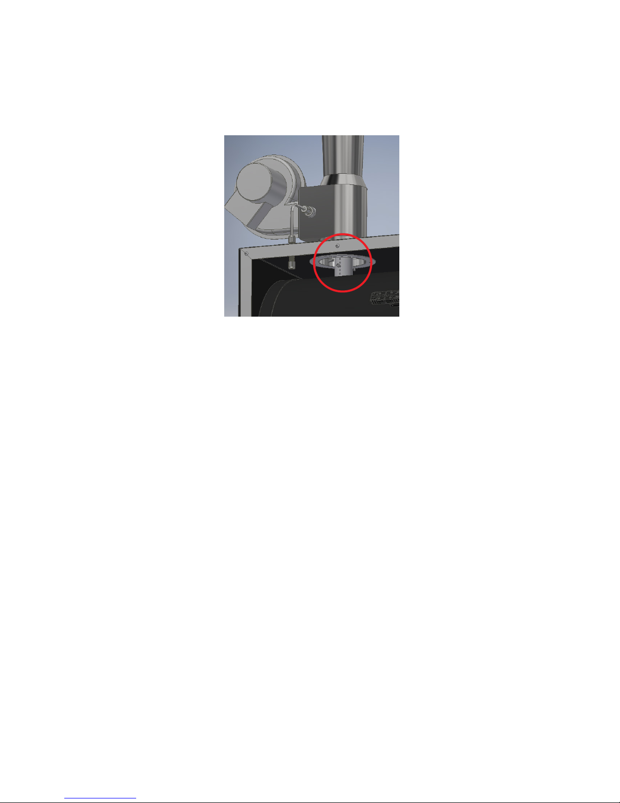
Changing the height of the pipe out of the Oxidizer chamber is done by positioning a screw in the side of the pipe.
The pipe has 5 or 6 holes drilled in it to allow adjustment of the pipe height outside the chamber. The entire pipe can
be pulled out of the Oxidizer chamber (with pliers if the pipe is hot), the screw repositioned to raise or lower the pipe
height. The Draft Inducer must be removed from the top of the unit so you can reach down inside the exhaust duct
with pliers to remove the pipe. The Draft Inducer must be replaced and restarted to measure the oven draft after any
change of the pipe height. See Figure D.1 for pipe location.
Figure D.1 - Oxidizer Pipe
It is important to recognize that Pyrolytic Ovens manufactured by ATS are not ordinary ovens. Pyrolytic Oven
systems are specialized, high-temperature systems specically designed and built for thermal cleaning of valuable
objects such as lab glass or metal parts. When organic residues are on the parts being cleaned, pyrolysis gases are
created during the cleaning process.
If the oven pressure is positive instead of slightly negative, these pyrolysis gases may escape into the room and
smoke or odor will be observed.
If the oven pressure is too highly negative then excessive air is sucked through the oven (even though it is tightly
sealed). This excessive leakage rate can prevent the oven from reaching its normal set-point (or struggle to reach its
set-point) and/or ignition of any combustible, pyrolysis gases may occur because of the high oxygen level caused by
excessive draft and leakage.
D.8 Pressure Switch for Draft Inducer Blower Motor
The Pyrolytic Oven is equipped with a pressure sensing switch mounted inside the main control box which senses
the pressure generated by the Draft Inducer when it is running. This pressure switch is interlocked to the oven
heaters so they cannot come on if the Draft Inducer blower motor is not running. If the pressure switch does not
close, then the power relay for the oven heater does not receive power.
The Draft Inducer pressure switch is connected to the Draft Inducer with a short piece of 1/4” metal tubing. This
tubing must be connected for the pressure switch to sense that the blower motor is running.
MAN - Pyrolytic Oven - REV: Original | D. Installation16
Page 22
E. Software Overivew
w
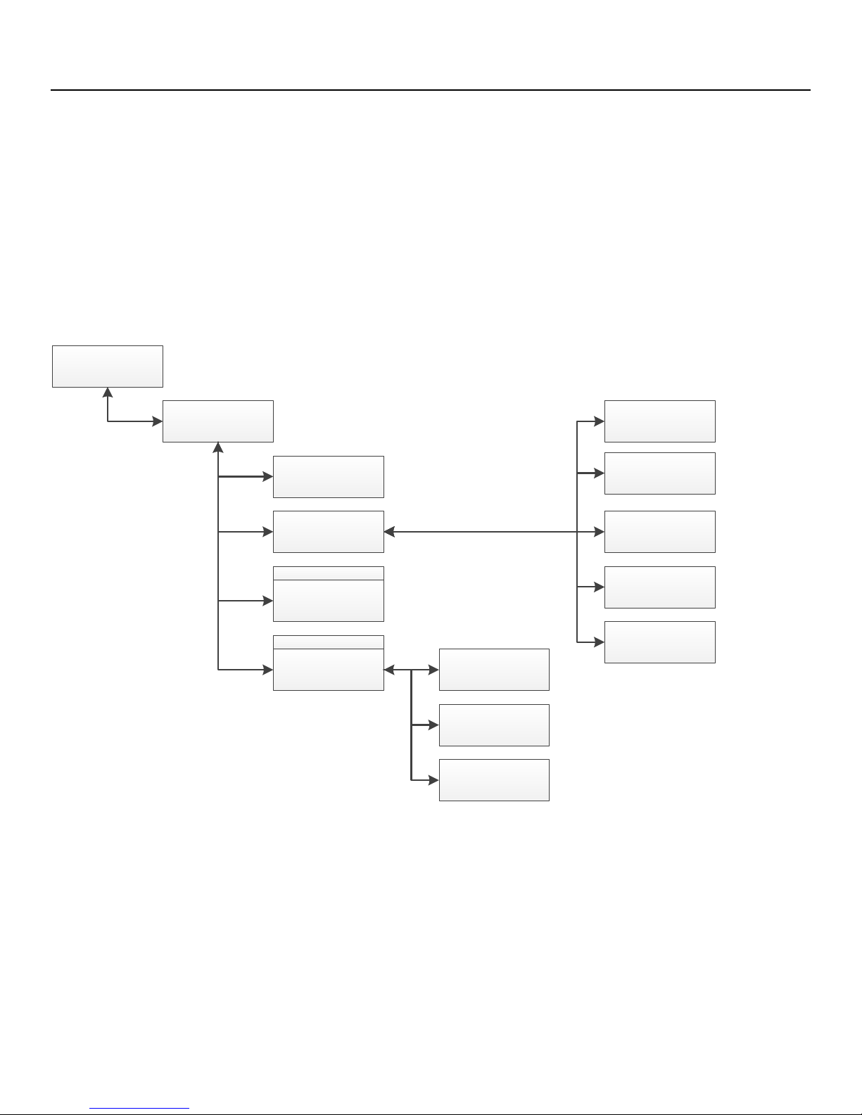
E.1 Software Screen Map
Figure E.1 shows the Pyrolytic Oven’s software screens.
Pyrolytic Oven Menu Flo
Main Screen
View
Cycle Time
Language
Settings IP Address
Password
Manual
Password
Password
Passwords
Reset Oven Clean
Time
Reset Catalyst
Replacement Time
VNC Password
Current Time
Delayed Cycle Start
Figure E.1 - Pyrolytic Oven Software Screen Map
MAN - Pyrolytic Oven - REV: Original | E. Software Overview 17
Page 23
E.2 Main Screen
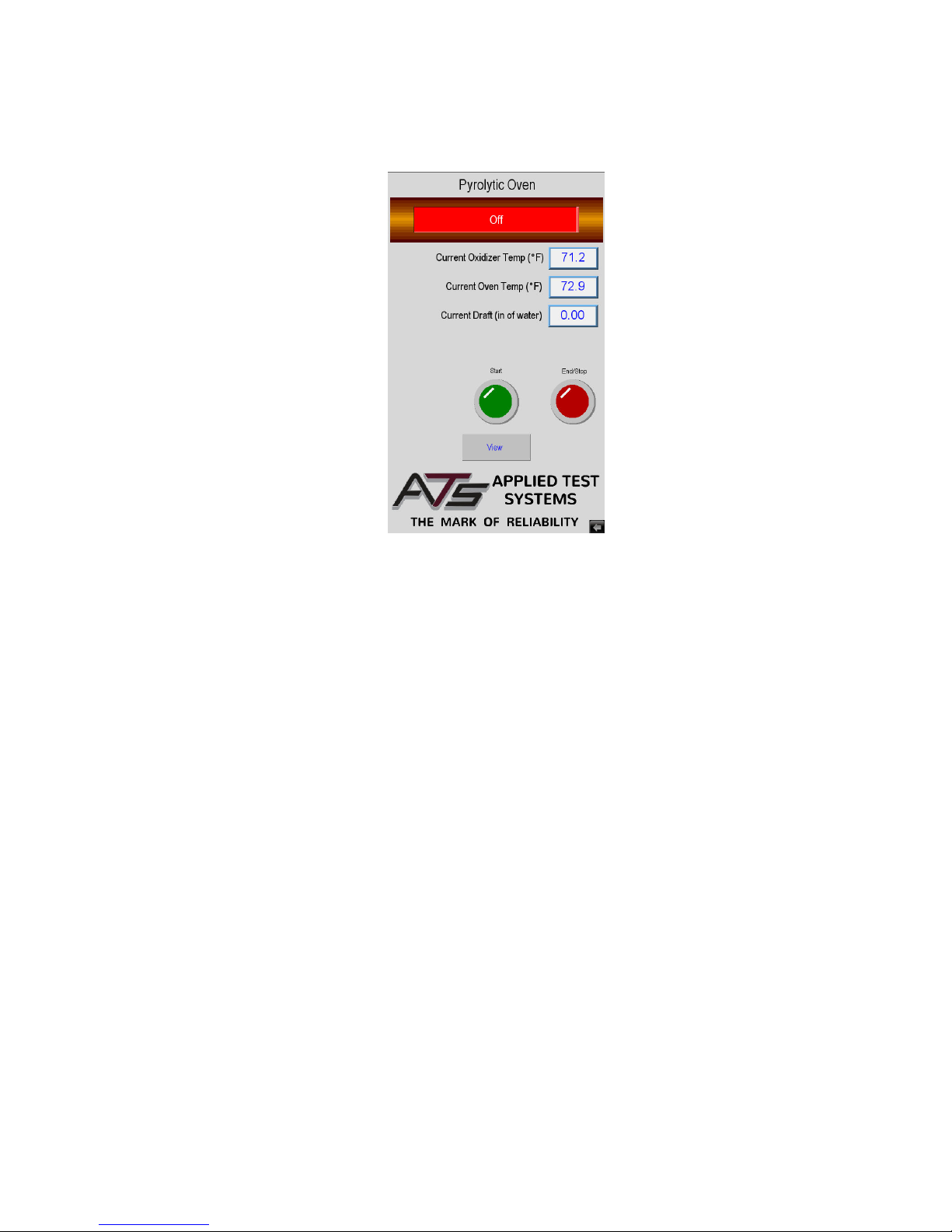
Figures E.2 shows the Main Screen that is shown when the Pyrolytic Oven is started. It allows you to setup and run
oven cycles.
Figure E.2 - Main Screen
This screen will show values for Oxidizer chamber temperature and Oven temperature. It also has several controls
to set-up and run the oven.
Start Button
Used to tell the system that parts are loaded, to start the oven cycle.
End/Stop Button
Used to tell the system to nish the cycle. It can also be used anytime the oven is in cycle to stop the cycle. When
the run cycle has nished this button will blink to show the cycle is nished. If this button is pressed anytime that the
oven is hot the system will go into cool down before you can open the door.
Alarm Button
If the system has an Alarm, Warning, or Fault the Alarm Button will be displayed and the Start Button is hidden. This
can be seen in Figure E.3. The operator will have to press the Alarm Button to go to the alarm screen and clear the
alarm condition before the system can start another cycle.
View Button
Used to get to all other screens in the system for Set-up. This will be hidden and a Graph Button will be displayed
when a cycle is running.
18 MAN - Pyrolytic Oven - REV: Original | E. Software Overview
Page 24
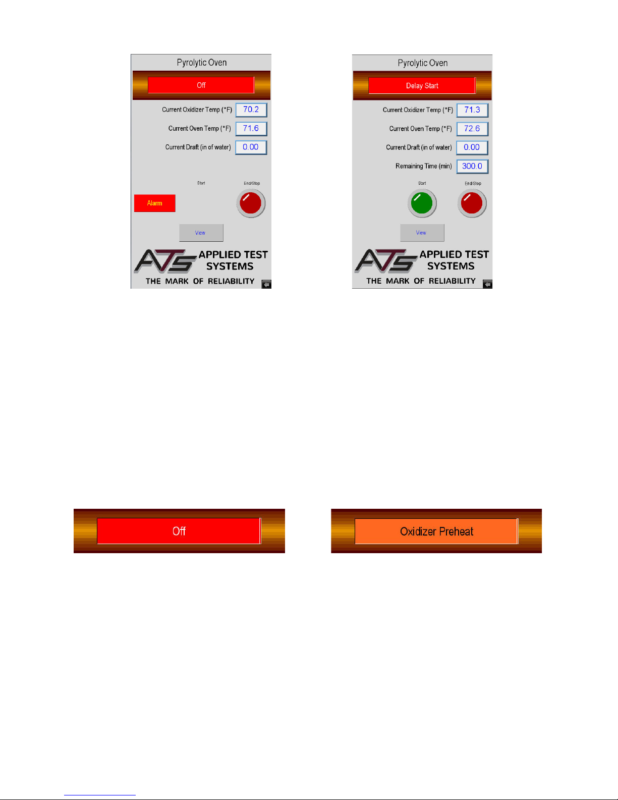
Figure E.3 - Main Screen, Alarm State Figure E.4 - Main Screen, Delay Start State
Figure E.4 illustrates what the Main Screen looks like when the system is in delay start state. Note the Remaining
Time displayed. This will show up for the Preheat Delay, Oven Soak, and the Run Cycle states and will display the
time remaining for this part of the cycle. The oven soak time may restart several times until it becomes stable at
temperature.
State Status Indicator Bar
Near the top of the display is a status bar that will show the current state of the oven cycle. Below are the dierent
states in the order that they usually run.
Figure E.5 - O State Status Bar Figure E.6 - Oxidizer Preheat State Status Bar
O State
Indicates that the system is sitting idle. No heat or cycle is running.
Oxidizer Preheat
Indicates that the oxidizer chamber is heating up. The system will stay here until the chamber is at temperature and
stable.
MAN - Pyrolytic Oven - REV: Original | E. Software Overview 19
Page 25
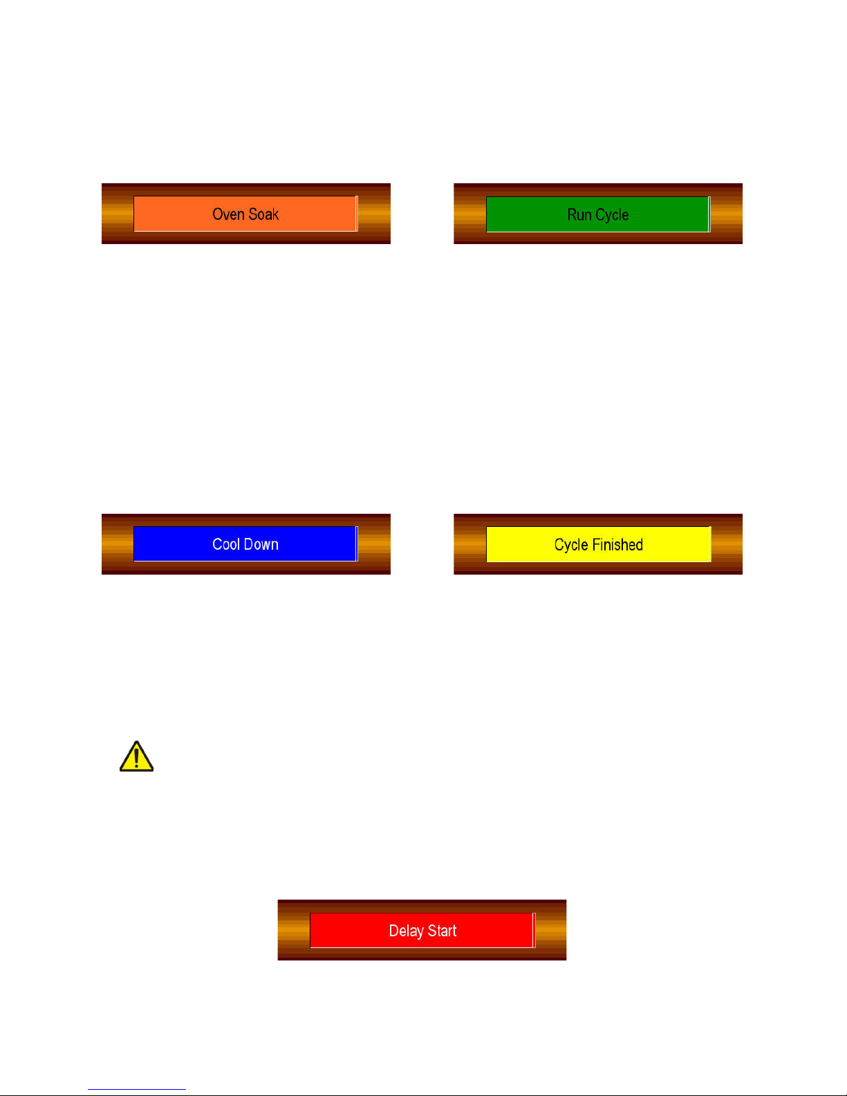
Oven Soak
Indicates the oxidizer chamber is stable at temperature, after which the oven starts to soak temperature. It is at this
stage that “smoke” is generated to burn o in the oxidization chamber. The Oxidization chamber and the oven will
interact so that the oxidization chamber is not overloaded. The system will stay here until the interaction dies down
and the oven is at soak temperature and stable.
Figure E.7 - Oven Soak State Status Bar Figure E.8 - Run Cycle State Status Bar
Run Soak
Starts when the oven is at the soak temperature and stable. The oven will change to the cycle temperature and sit in
this state until the cycle time has expired.
Cool Down
Starts when the run cycle has timed out. The oxidizer chamber and oven shut o and start to cool down. The system
will stay here until the oven drops below the cool down temperature.
Figure E.9 - Cool Down State Status Bar Figure E.10 - Cycle Finished State Status Bar
Cycle Finished
Starts when the oven temperature has dropped below the cool down temperature and the system is waiting for the
operator to press the End Button and remove the parts.
CAUTION: When the oven unlocks to allow the removal of parts, remember that they are still
500°F and you will need protective equipment to handle them.
Delay Start
Indicates the system has been set up to start the oven cycle automatically after a time delay. You can think of this
like a “coee timer”.
Figure E.11 - Delay State Status Bar
20 MAN - Pyrolytic Oven - REV: Original | E. Software Overview
Page 26
E.3 View Screen
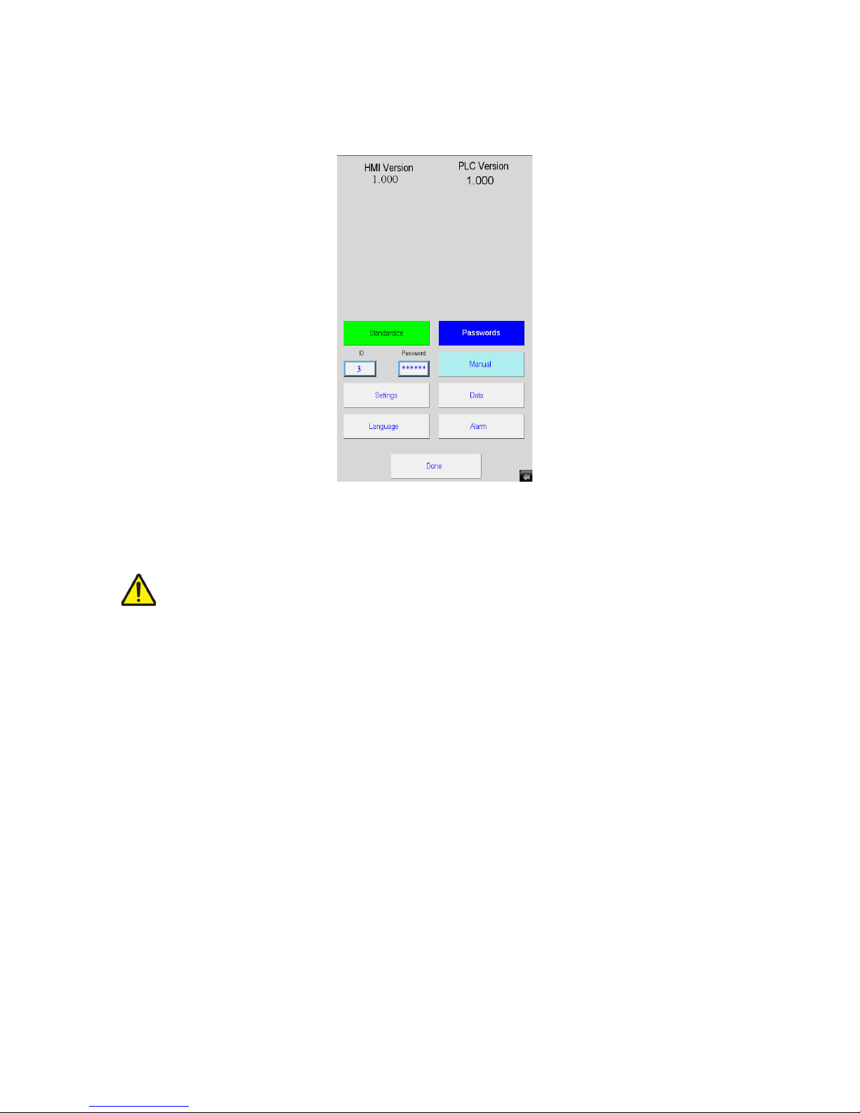
Figure E.12 shows the View Screen. It is shown anytime the View Button is pressed on the Main Screen. It allows
access to the rest of the screens in the system.
Figure E.12 - View Screen
NOTE: If the system is not idle this button is not visible and you will not be able to get to this
screen to make changes.
The screen will show the current version of the software in the PLC and HMI. This is very important information, and
is most often ask for when calling into ATS service.
ID
A user ID should be set to the user access you wish to use.
Password
Associated with the User ID and used to access other screens. When the correct ID and Password are entered
other buttons (colored on the above screen) will be displayed.
Manual Button
Will not be displayed until the correct ID and Password has been entered. Once it is displayed, pressing it will go to
the manual screen. (Default ID: 1, Password: 111111).
MAN - Pyrolytic Oven - REV: Original | E. Software Overview 21
Page 27

Passwords Button
Will not be displayed until the correct ID and Password has been entered. Once it is displayed, pressing it will go to
the password screen. (Default ID: 2, Password: 222222).
Standardize Button
Will not be displayed until the correct ID and Password has been entered. Once it is displayed, pressing it will go to
the standardize screen. (Default ID: 3, Password: 333333).
Settings, Language, Data, and Alarm Butons
Each take you to their screens which are described later in this section.
Done Button
Returns you to the Main Screen.
E.4 Language Screen
Figure E.13 shows the Language Screen that is shown when you press the Language Button on the View Screen. It
allows you to set the language used in all the screens.
Simply select your language of choice then press the Done Button to go back to the View Screen.
22 MAN - Pyrolytic Oven - REV: Original | E. Software Overview
Figure E.13 - Language Screen
Page 28
E.5 Settings Screen
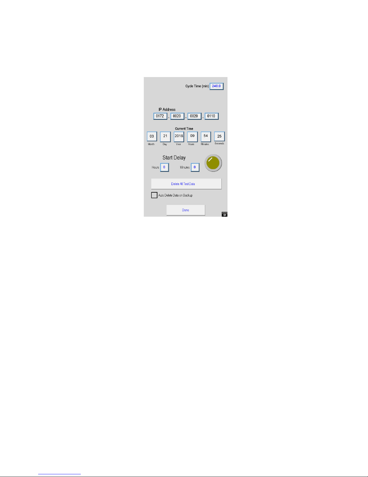
Figure E.14 shows the Settings Screen. It is shown when the Settings Button is pressed on the View Screen. It
allows set up of the system.
Figure E.14 - Settings Screen
Cycle Time
The amount of time the oven sits at cycle temperature before it shuts o and goes into cool down.
IP Address
Used to allow someone at a remote location to monitor the system using a VNC viewer program.
Current Time
Allows the operator to set the current time of the system. This aects the oven clean and catalyst replacement
warning times. It is also used for alarm and data logging times.
Preheat Delay
Used to allow the system to be set up to start automatically after a time delay. You can think of it like a “coee timer”.
Just enter the Hours and Minutes you wish to wait before oven start and press the yellow button. The button will light
to show that a delay has been set. The delay button is a toggle switch, so to turn o a delay that has been started
just press the button again. Note the status of the system will show Delay Start when it is active and the remaining
time before cycle start is shown.
MAN - Pyrolytic Oven - REV: Original | E. Software Overview 23
Page 29
Done Button
Will return you to the View Screen.
E.6 Manual Screen
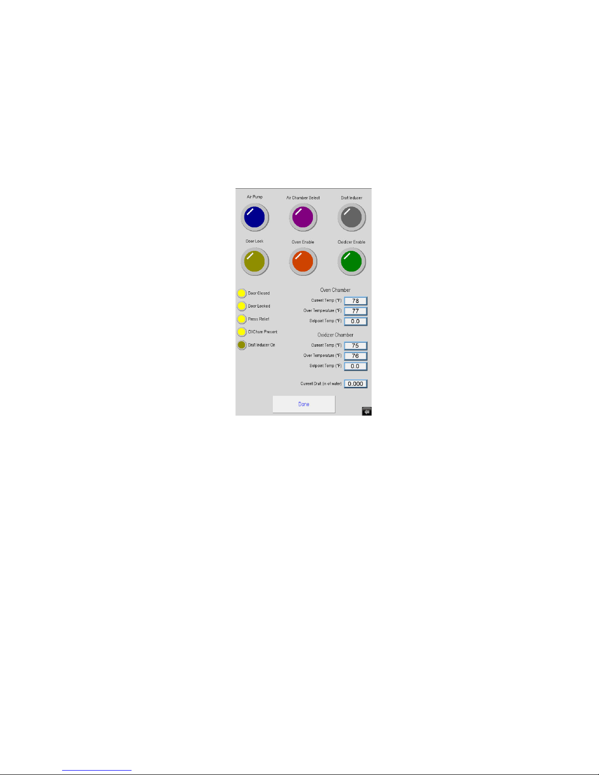
Figure E.15 is the Manual Screen. It is shown when the Manual Button is pressed on the View Screen. It allows
trouble shooting of the system.
Caution should be used as all system safety features are disabled during Manual operation.
Figure E.15 - Manual Screen
Six Buttons Across Top of Screen
Allow you to turn individual sub-systems on and o to test them.
Four Indicators on the Left Side
Show which inputs the system sees.
Values on the Right Side
Show the current temperature and over temperature being reported for the oven and oxidizer chambers.
Set Point for Both Oven and Oxidizer Chamber
These values are locked at a maximum value of 500° to eliminate the risk of explosion.
24 MAN - Pyrolytic Oven - REV: Original | E. Software Overview
Page 30

Current Draft
Shown to help in the adjustment of the draft tube during ventilation set-up.
Done Button
Will return you to the View Screen.
MAN - Pyrolytic Oven - REV: Original | E. Software Overview 25
Page 31

F. Operation
F.1 Important Operation Notications
There are several notications that may appear when operation of the Pyrolytic Oven is initiated. These are broken
into three categories of severity: warnings, alarms, and faults. DO NOT IMMEDIATELY SHUT THE MACHINE
DOWN WHEN THESE NOTIFICATIONS APPEAR. Allow unit to continue cycle to completion. If the unit is required
to shut down, it will do so on its own.
Warnings, alarms, and faults are color coded in yellow, orange, and red. Refer to the list below for descriptions of
these common operation notications. If additional assistance is required, contact the ATS Service Department at
+1-724-283-1212.
Warnings (Yellow)
These do not stop the cycle but are things that you may wish to check after it is complete. Do not shut the machine
down if these appear. They may indicate:
• 6 Month Clean Warning
• 1 Year Catalyst Replacement Warning
• Low Draft Warning
Alarms (Orange)
These do not stop the cycle but are things that should be checked before next cycle. Do not shut the machine down
if these appear. They may indicate:
• Low Draft Alarm
Faults (Red)
These are faults that will automatically stop the current cycle. They must be xed before next cycle.
• Oven Chamber Over-Temp
• Oxidizer Chamber Over-Temp
• Oven Chamber Over-Press
• Standardization Error
• Door Lock did not Engage
• Draft Inducer Error
• Low Draft Fault
F.2 Initial Start-Up: Empty Load
Do not operate the oven with a load if the correct, slight negative draft/pressure in the oven chamber is not
achieved. Refer to Installation Instructions or call the ATS Service Department at +1-724-283-1212 for technical
assistance.
26 MAN - Pyrolytic Oven - REV: Original | F. Operation
Page 32

1. After the Pyro-Clean Oven has been installed and properly vented with the correct draft, it is ready to operate.
However, it is best to run the oven through a short cleaning cycle with it empty to:
a. Familiarize the operator with the normal operating sequence and location of the controls.
b. Check that all controls, indicating lights, and components are operating normally.
2. The oven door latch is a compression type and must be turned completely to the right until the door “pulls up” and
is completely latched.
3. When the main power toggle switch is turned on, the indicator light and HMI should power up. For this test only,
set the Cycle Time on the Settings Screen to about 10 minutes.
4. To start the empty test run, press the Start Button. The status bar will change to Oxidizer Preheat on the HMI. The
oven exhaust fan will be powered at this time and you may hear a slight noise from the exhaust. A small air pump
which feeds a stream of air to the oxidizer is started at the same time. The Afterburner heaters come on and you
should see the Afterburner temperature begin to rise to its normal set point of 1300°F. Typical heat-up times for the
Afterburner to reach 1300°F is about 80 minutes. 10 minutes after the oxidizer reaches 1250°F, the status bar will
change to Oven Soak, the oven will turn on, and the door will lock.
5. During an empty run, the oven will heat up to its ramp/soak set-point, typically 900°F and control at this
temperature for the stable time of 180 minutes. Then the status bar will change to Run Cycle, the oven heat up will
continue to the normal set-point of the oven temperature controller, 950°F. When the oven temperature reaches
940°F, a timer will start for the cycle time set. When it times out, the status bar will change to Cool Down, and both
the oxidizer and the oven will shut o.
6. After the oven has cooled down to below 500°F, the status bar will change to Cycle Finished, the draft inducer,
air pump, and door lock will all turn o. At this point press the End/Stop button to nish the cycle. The door can be
opened to allow faster cooling. However, in a normal cleaning cycle for glass or metal parts, it is best to let the oven
cool down as much as possible to minimize the handling of hot parts.
F.3 Starting a Normal Load of Dirty Glasswear or Metal Parts
Tips on Loading
The glass or metal parts should have relatively small amounts of organic residues, on the order of grams to a couple
pounds. Parts with very heavy residues of combustible organic matter should not be processed in the Pyrolytic
Oven. A practical limit for the oven is in the range of 1 to 2 pounds of asphalt or other organic residues per load/
cycle.
Whenever possible, always load the parts to promote drainage of any visible residues. The oven is furnished with
a metal tray on the chamber bottom to catch molten residues which drains o the parts. This will give the best
cleaning results. Longer cycle times will virtually always be required if the contaminants are not allowed to drain out
of the parts during the pyrolysis cleaning cycle.
The Pyrolytic Oven is furnished with two racks (trays) to hold the metal parts. Both of these racks have a stainless
steel wire mesh on the bottom which holds catalyst pellets which help destroy the pyrolysis gases formed during the
cleaning cycle. Use both trays during every cycle. Both must not be left out of the oven under any circumstance. A
metal drip pan on the bottom of the oven is furnished to catch any dripping. The drain pan helps prevent any plastic
or polymer from running down on the oven oor and onto the door gaskets where the residue could cool, harden
and tear o the gasket when the door is opened. Always place any metal parts with the heaviest residues toward the
MAN - Pyrolytic Oven - REV: Original | F. Operation 27
Page 33

back of the oven to prevent any organic material from dripping on the oven door gaskets.
F.4 Cycle Times for Cleaning
The Pyrolytic Oven is equipped with an Automatic Cycle Time Feature which adjusts itself to the load placed in
the oven. The cleaning time is limited by the processing speed of the oxidizer. The more asphalt or other organic
residues on the parts, the more smoke that will be evolved o the parts during the thermal cleaning process.
The oxidizer is equipped with a temperature sensor and controller which monitors the amount of smoke evolved
o the parts and controls the heat-up rate of the oven to prevent the oxidizer from being overwhelmed by too much
smoke. The oxidizer control system will cut o the oven heaters if too much smoke is being produced. The oven
temperature seeks whatever temperature is necessary to produce the maximum amount of smoke the oxidizer can
process. Thus the oxidizer actually controls the heat-up rate if sucient plastic residues are on the parts. When
all of the organic residues are pyrolyzed/vaporized o of the parts, smoke evolution will fall o, allowing the oven
temperature to climb to the normal processing temperature of 900°F to nish o the cleaning process.
A cycle time is set on the Setting screen. The Factory setting of 1 hour (3-4 for asphalts) is recommended for most
applications. The Cycle Time does not start until the oven temperature reaches within -10°F of the set-point of the
Oven Temperature Controller. With a normal set-point of 950°F, the Cycle Time does not start timing until the oven
temperature reaches 940°F.
The Cycle Time does not actually start until the oven temperature is within minus 10°F of set-point. This ensures
that the dialed amount of time is a true “time at temperature”. For safety reasons, never set the Cycle Time at less
than 1 hour. This ensures that volatile, pyrolysis gases are exhausted from the oven before the oven shuts down.
For most organics, pyrolysis and vaporization into smoke will actually begin below 900°F, so it is quite common for
the oven temperature to seek a level of about 700 to 800°F while the maximum amount of smoke is being vaporized
o of the parts. After the bulk of the smoke is gone, the Oxidizer controller senses this and allows the oven to heat
up to process set-point, typically 950°F. For large glassware, the parts themselves may serve as heat-sinks and
allow the oven temperature to reach set-point even though the parts are too cool to produce enough smoke to turn
o the oven heaters. In this case, the oven temp may reach set-point for 20-30 minutes until the glass parts get hot
enough to start signicant smoke production. Then the Oxidizer Controller will take control of the cleaning process
and limit the oven temperature to that which produces the maximum smoke, processing rate of the Oxidizer. Thus
the oven temperature may reach set-point until enough smoke is produced to drive the oven temperature to a lower
level. After all the smoke is vaporized away, the oven temperature is then allowed to climb to 950°F and nish the
cleaning cycle.
F.5 Cool-Down Before Removing the Glasswear or Metal Parts
When the cycle ends, the oven and afterburner heaters shut o, ending the cleaning cycle. The oven exhaust fan
continues to run to help remove the heat as the oven and afterburner cools. The oven will need to cool to at least
500°F before the door is unlocked and can be opened. Where possible, it is best to let the oven cool down low
enough that the parts can be removed and handled comfortably without special gloves or precautions.
28 MAN - Pyrolytic Oven - REV: Original | F. Operation
Page 34

F.6 Additional Operation Precautions
WARNING: Do not rinse glassware or metal parts with ammable solvents such as acetone,
toluene, etc. and then clean the parts in the oven without allowing the solvents to dry.
Flammable solvents such as acetone or toluene will ignite or explode inside the oven if present
in sucient concentration.
CAUTION: Do not clean remove silicon materials in the oven as it will poison the catalytic
system of the oven (and afterburner, if so equipped).
WARNING: Do not clean any sealed vessel, glass or metal, which could develop explosive
forces and rupture inside the oven.
WARNING: Do not overload the oven with metal parts containing heavy organic residues. The
maximum load for the Pyro-Clean Oven is 1 to 2 pounds of polymer or plastic. Consult Applied
Test Systems if heavier loads need to be cleaned.
CAUTION: Do not operate the oven without the special catalytic trays inside the oven. This
trays contain a special catalytic material which helps inert the oven atmosphere and destroys
the pyrolysis gases produced during the cleaning process.
F.7 Operation Instructions
1. Turn the power switch on the front of the Pyrolytic Oven to the ON position. The POWER light located on the front
of your oven will light up and the HMI display will power on. The status display will show “O”.
2. Select “View” on the HMI Main screen.
3. Select “Settings” on the HMI View screen.
4. Verify that the “Cycle Time” is set up to the value you wish. A setting of 2 hours is recommended for most
applications. However, for removing asphalts, a setting of 4 to 5 hours is recommended as asphalts are among the
more dicult organics to remove.
5. Select “Done” to return to the “View” screen.
6. Select “Done” to return to the “Main” screen.
7. Load the oven with the parts that you wish to clean. Parts should be loaded to promote drainage. Read “Principles
of operation and use” section before loading parts to verify what the pyrolytic oven can clean.
8. Close the oven and latch it.
9. Press the “Start” button to start the oxidizer chamber heating to 1300°F. The draft inducer and air pump will turn
on. The status display will change to “Oxidizer Preheat”.
10. Once the oxidizer temperature is stable (1300°F ±50°F for 10 minutes). The oven door will lock and the oven will
MAN - Pyrolytic Oven - REV: Original | F. Operation 29
Page 35

start to heat to 900°F. The status display will change to “Oven Soak”.
11. In the “Oven Soak” stage, the oven will heat up creating smoke that gets burnt o in the oxidizer chamber. If the
oxidizer temperature goes over 1500°F it will shut o the oven heat until the temperature goes below 1350°F. It will
then turn the oven back on. This cycle will continue back and forth until the smoke generation dies down and the
oven temperature is stable (900°F ±10°F for 180 minutes). The oven will then heat to 950°F and the air select will
shift the air ow from the oxidizer to the oven. The status display will change to “Run Cycle”.
12. Once the oven gets to cycle temperature (950°F ±10°F) it will sit for the cycle time.
13. Once the cycle time has expired, both the oxidizer and oven chamber heat will turn o and the status display will
change to “Cool Down”.
14. When the oven temperature drops below 500°F the draft inducer and air pump will turn o and the oven door will
unlock. The status display will change to “Cycle Finished”.
15. At this point press the “End\Stop” button to return the system to “O”.
CAUTION: When the oven unlocks to allow the removal of parts, remember that they are still at
500°F and you will need protective equipment to handle them.
30 MAN - Pyrolytic Oven - REV: Original | F. Operation
Page 36

G. Troubleshooting
G.1 Troubleshooting Electrical Problems
A ladder wiring diagram for the Pyrolytic Oven is included in this manual, along with a drawing of the inside of the
control box showing the lay-out of the parts and their identication. A qualied electrician should nd this sucient
to locate any electrical problems with the unit. The oven electrical circuit has a number of fuses, so check rst to
determine if a blown fuse is the problem. If assistance is needed to determine the problem, contact Applied Test
Systems and ask for technical help.
G.2 Manual Operation to Check Electrical Operaton
A manual operation screen is included so that all parts can be controlled manually to check operation and help
troubleshoot the system.
NOTE: In manual operation the temperature control systems will only allow the temperature to
be set to 500°F as a safety precaution.
MAN - Pyrolytic Oven - REV: Original | G. Troubleshooting 31
Page 37

H. Maintenance
H.1 Door Seals and Gaskets
The oven door has two gaskets. One is a high temperature gasket which serves both as a seal and a heat barrier
to protect the silicone gasket. Periodic replacement of the high temperature gasket is considered necessary routine
maintenance. The high temp gasket contains an inner core stainless steel mesh, covered with woven glass ber.
Because of its porous nature, the high temp gasket will gradually absorb condensed smoke or vapors from inside
the oven and begin to harden. This gasket can be recycled and used again by removing it, replacing it with a new
high temp gasket, and cleaning the old gasket inside the oven at the same time a typical load of glass or metal parts
are cleaned. The blackened, old gasket will come out of the oven looking almost new. The gasket can be used again
unless it was mechanically torn, ripped, or otherwise damaged during removal.
The silicone gasket mounted on the oven door serves as a second seal for the oven chamber and prevents
excessive air leakage inside the oven. Parts should never be loaded such that any molten organic residues drains
from the metal parts, misses the metal pan on the oor of the oven, and runs down on the door gaskets. When cool,
such material can harden and rip the door gasket o when the door is opened.
H.2 Cleaning the Oven Trays
Both of the two oven trays has a bottom of stainless steel wire mesh containing special catalytic pellets which help
destroy the pyrolysis gases inside the oven chamber by reaction with the oxygen in the oven atmosphere. As these
trays get dirty and accumulate inorganic ashes, it should be removed and rinsed with water to get the catalyst
pellets free of obstruction or coatings which would prevent it from working.
H.3 Removal of Ashes and Pigments
Ashes, pigments, dirt, or other inorganic matter left from the cleaning process should be removed as necessary to
maintain good housekeeping. Do not allow such material to collect at the door gaskets where it might interfere with a
good, tight seal.
H.4 Periodic Empty Tests & “Self-Cleaning” Cycles
Every 3 to 6 months, run an empty test run (cycle) during daytime hours so the operator of the oven can verify that
the oven controls are working properly. With no glassware in the oven, this test run will also act as a “self-cleaning”
cycle and help remove any residual, built-up carbon residues which may be deposited by numerous moderate to
heavy loads of organic contaminants.
H.5 Cleaning of Draft Inducer Fan
Periodically, the squirrel cage blower of the Draft Inducer should be blown out with compressed air to remove
accumulated dust and lint.
MAN - Pyrolytic Oven - REV: Original | H. Maintenance32
Page 38

H.6 Replacement of Parts
When electrical components must be replaced, refer to the Parts List included in this manual for the appropriate
descriptions. Consult Factory for current prices. Electrical parts on the oven are warrantied for one year.
Every Six Months
1. Exchange Hi-Temp door gasket:
a. The oven door has two gaskets. One is a high temperature gasket that serves both as a seal and
a heat barrier to protect the silicone gasket. The high temp gasket contains an inner core stainless
steel mesh, covered with woven glass ber. Because of its porous nature, the high temp gasket will
gradually absorb condensed smoke or vapors from inside the oven and begin to harden.
b. The high temperature gasket can be recycled and used again by removing it, replacing it with
a new high temp gasket, and cleaning the old gasket inside the oven. The blackened, old gas-ket
will come out of the oven looking almost new. The gasket can be used again unless it was mechanically torn, ripped, or otherwise damaged during removal.
c. During the cleaning cycle for the gasket, verify that the controls are working properly.
2. Check draft
a. Turn the power on. Go to Manual screen and start the Draft Inducer.
b. Move the draft control to make sure the range of draft pressure can be adjusted from at least
0.02 to 0.06.
c. Leave the draft control in position to give a draft pressure of about 0.04.
d. Remember, the draft sensor is only a measuring device; it only reads the draft and does not
create draft. Also, the draft sensor is set to read a negative pressure in the oven as positive
pressure on the screen (essentially it reads backwards).
3. Clean draft inducer blower (exhaust blower)
a. The squirrel cage blower of the draft inducer should be blown out with compressed air to remove
accumulated dust and lint.
4. Removal of Ashes and Pigments
a. Ashes, pigments, dirt, or other inorganic matter left from the cleaning process should be removed
as necessary to maintain good housekeeping. Do not allow such material to collect at the door
gasket(s) where it might interfere with a good, tight seal.
5. Clean the Oven Trays
a. Both trays contain special catalytic pellets in a stainless steel mesh. The catalyst helps destroy
the pyrolysis gases inside the oven chamber by reaction with the oxygen in the oven atmosphere. It
should be removed and rinsed with water to get the catalyst pellets free of obstruction or coatings,
which would prevent it from working.
MAN - Pyrolytic Oven - REV: Original | H. Maintenance 33
Page 39

b. Empty the catch tray in the bottom of the oven (into oor sweeps).
6. Clean Electronics Cabinet
a. Vacuum out any areas in the electronics cabinet that appear dirty.
Every Twelve Months
Perform the 6 month steps, plus:
1. Replace catalyst trays
a. Discard the old trays containing the catalyst and replace them with a new ones.
b. Order replacement catalyst trays.
H.7 Spare Parts List
The following should be kept on hand for regular maintenance:
• Tray, Stainless Steel, Catalytic, QTY 1
• Thermocouple, Oven Control Type K, QTY 1
• Thermocouple, Oven Hi-Limit Type K, QTY 1
• Thermocouple, Oxidizer Control, Type K, ¼” by 6” long, 36” leads, QTY 1
• Gasket, Door Replacement, Hi-Temp, QTY 1**
Part No. Description
XXXXXXX Gasket, Door Replacement, Hi-Temp, 78”
XXXXXXX Gasket, Door Replacement, Silicone, 88”
XXXXXXX Thermocouple, Oven Type K
XXXXXXX Heater Elements, Model 3 Oven
Part No. Afterburner (Oxidizer) Parts
XXXXXXX Heater Element, 1060 watts (uses 2)
XXXXXXX Catalyst, Ceramic Honeycomb, 5” Dia by 2”
MAN - Pyrolytic Oven - REV: Original | H. Maintenance34
Page 40
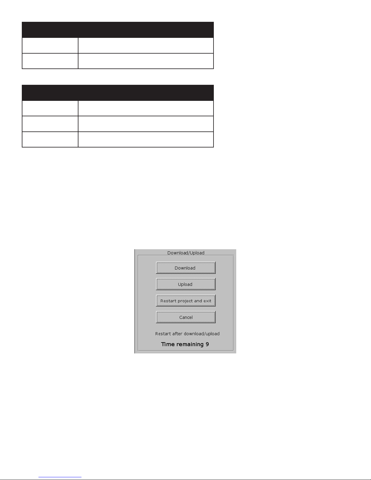
Part No. Afterburner (Oxidizer) Parts
XXXXXXX Thermocouple, K, 1/8” by 6” long, 36” leads
XXXXXXX Air Pump, Oxidizer
Part No. Oven Trays & Pans
XXXXXXX Tray, S.S., Regular
XXXXXXX Tray, S.S., Catalytic
XXXXXXX Pan, Drain, S.S.
H.8 New HMI Software
From time to time a new software version may come out for the HMI. Below are instructions for downloading the
new software. The new version of software must be on the root of a ash drive.
1. Power up the machine.
2. Open USB port cover and install ash drive containing the new version of software into the USB port.
Figure H.1 - Pop-Up Menu
3. After a few seconds the menu in Figure H.1 will appear. Choose Download.
4. Another pop-up menu will appear prompting for a password. Using the keyboard displayed on the screen (Figure
H.2), enter 111111. Check the box that indicates Download Project les and uncheck the boxes that indicate Clear
History les and Download History les and select OK.
MAN - Pyrolytic Oven - REV: Original | H. Maintenance 35
Page 41
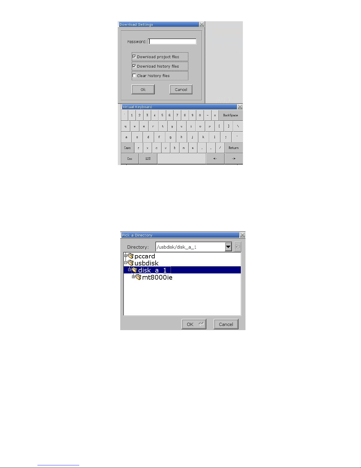
Figure H.2 - Second Pop-Up Window
5. Next will appear 2 subdirectories - pccard and usbdisk. Click usbdisk, select disk_a_1, and click OK.
Figure H.3 - disk_a_1
6. The necessary les will now be downloaded.
7. When done, remove the ash drive and replace the USB port cap.
MAN - Pyrolytic Oven - REV: Original | H. Maintenance36
Page 42

Appendix A: Warranty
Your Applied Test Systems product has been manufactured and inspected by experienced craftsmen. Applied Test
Systems warrants, for the original purchaser, each product to be free from defects in material and workmanship for
a period of thirteen (13) months from date of shipment or twelve (12) months from date of installation - whichever
comes rst. This warranty does not apply to failures caused by normal usage, misuse, or repair or service by
unauthorized personnel, nor does it cover limited life electrical components which deteriorate with age such as
tubes, lamps, fuses, and heaters. Load cells are covered for manufactured defects only - incidents of over load or
other customer misuse are not covered under warranty. The warranty does not extend to products not manufactured
or assembled by Applied Test Systems.
This warranty is expressly limited to the repair, replacement, or adjustment of the product at Applied Test Systems’
option. The product must be returned to the Applied Test Systems factory or an authorized repair center. Applied
Test Systems shall not be liable for any labor, transportation, or installation costs that may arise in connection with
the product or return.
To obtain warranty service:
1. Applied Test Systems must be promptly notied in writing of the defect.
2. Upon receipt of written authorization, said defective equipment is returned as directed, with transportation
charges prepaid by the buyer and –
3. Applied Test Systems examination of such equipment discloses to its satisfaction that the defect exists and
was not caused by negligence, misuse, improper installation, accident, or unauthorized repair or alteration.
This warranty is in lieu of all other warranties, expressed or implied, including the implied warranty of merchantability
or tness for particular purpose. In no event shall Applied Test Systems be liable for direct, indirect, special,
incidental, collateral, or consequential damages.
The aforementioned provisions do not extend the original warranty period of any article that has been either repaired
or replaced by Applied Test Systems.
Applied Test Systems reserves the right to change published specications.
MAN - Pyrolytic Oven - REV: Original | Appendix A: Warranty 37
Page 43
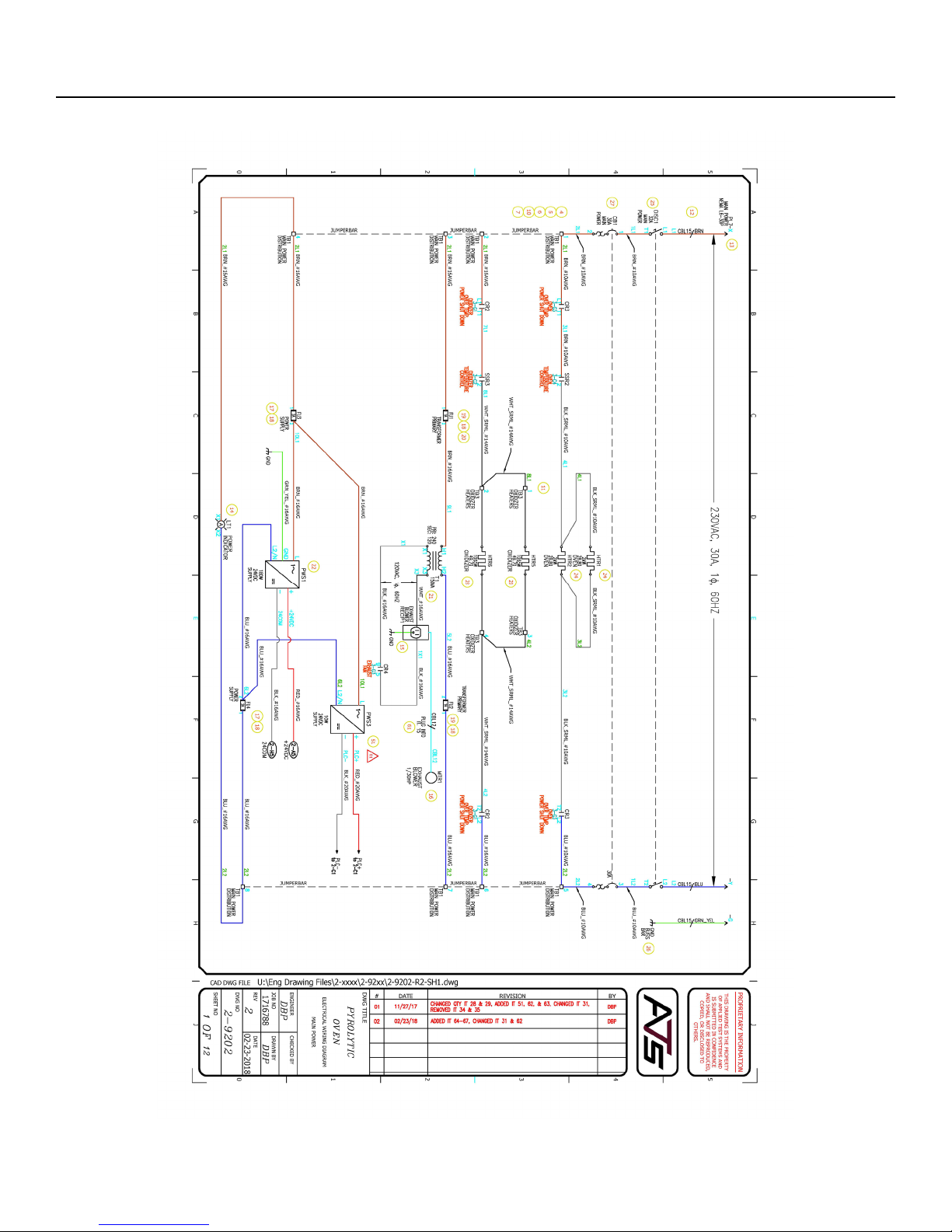
Appendix B: Wiring Diagrams
MAN - Pyrolytic Oven - REV: Original | Appendix B: Wiring Diagrams38
Page 44
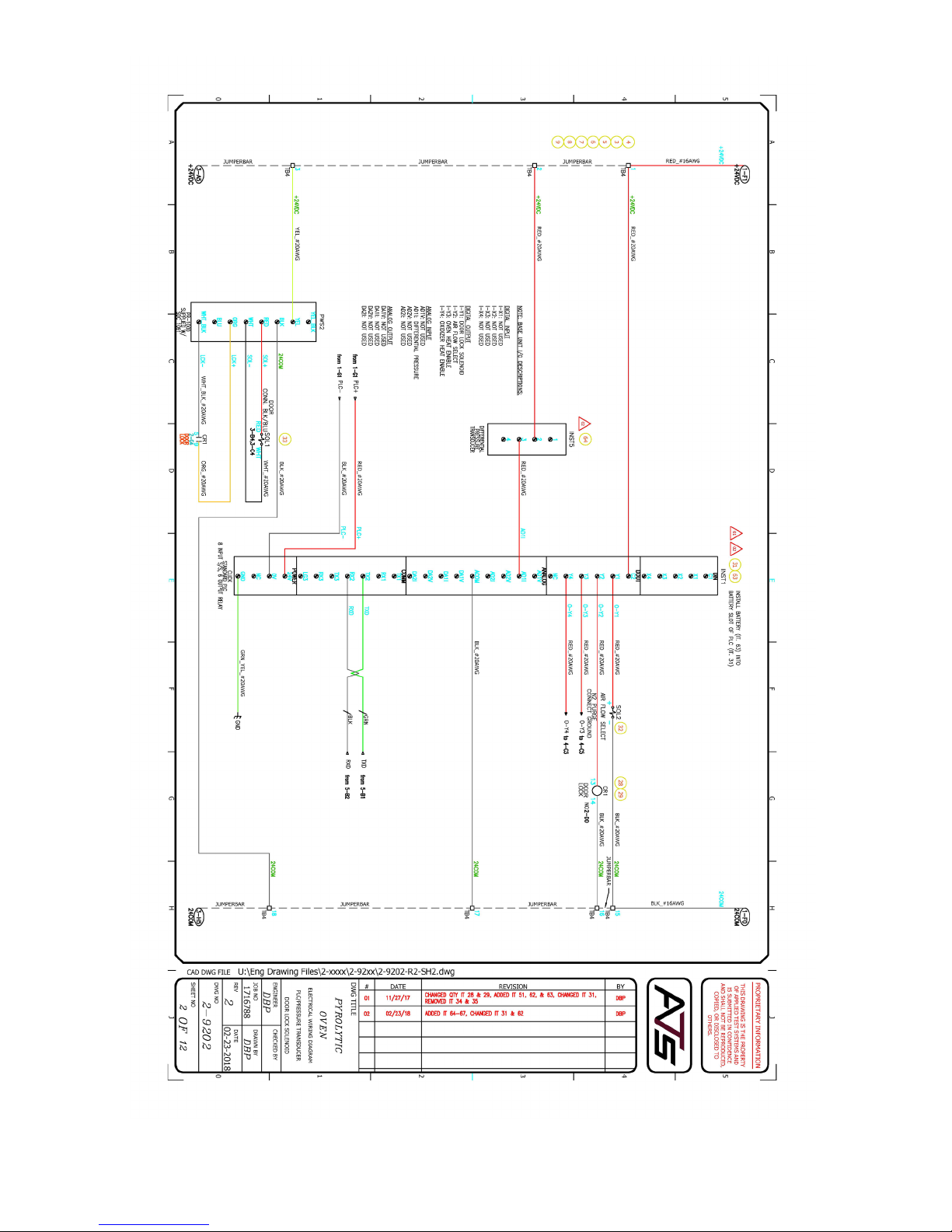
MAN - Pyrolytic Oven - REV: Original | Appendix B: Wiring Diagrams 39
Page 45
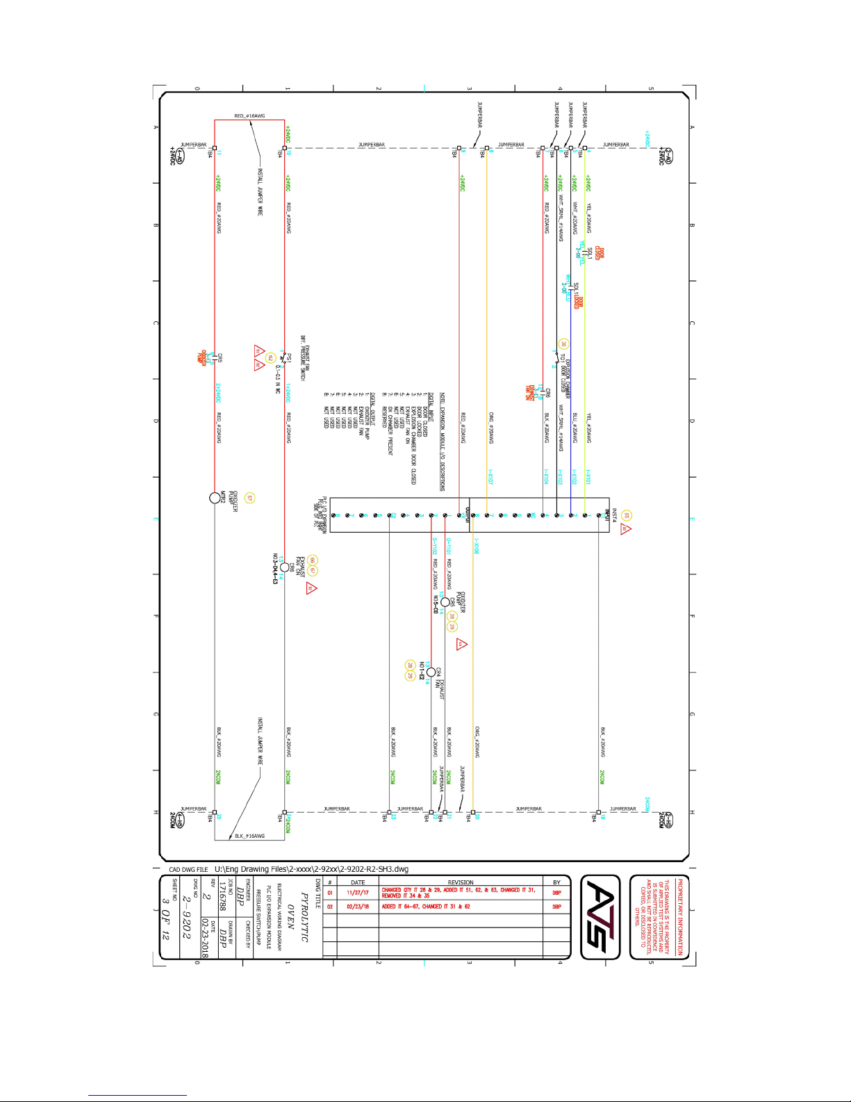
MAN - Pyrolytic Oven - REV: Original | Appendix B: Wiring Diagrams40
Page 46
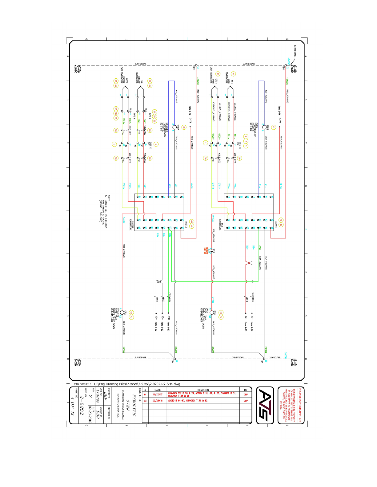
MAN - Pyrolytic Oven - REV: Original | Appendix B: Wiring Diagrams 41
Page 47
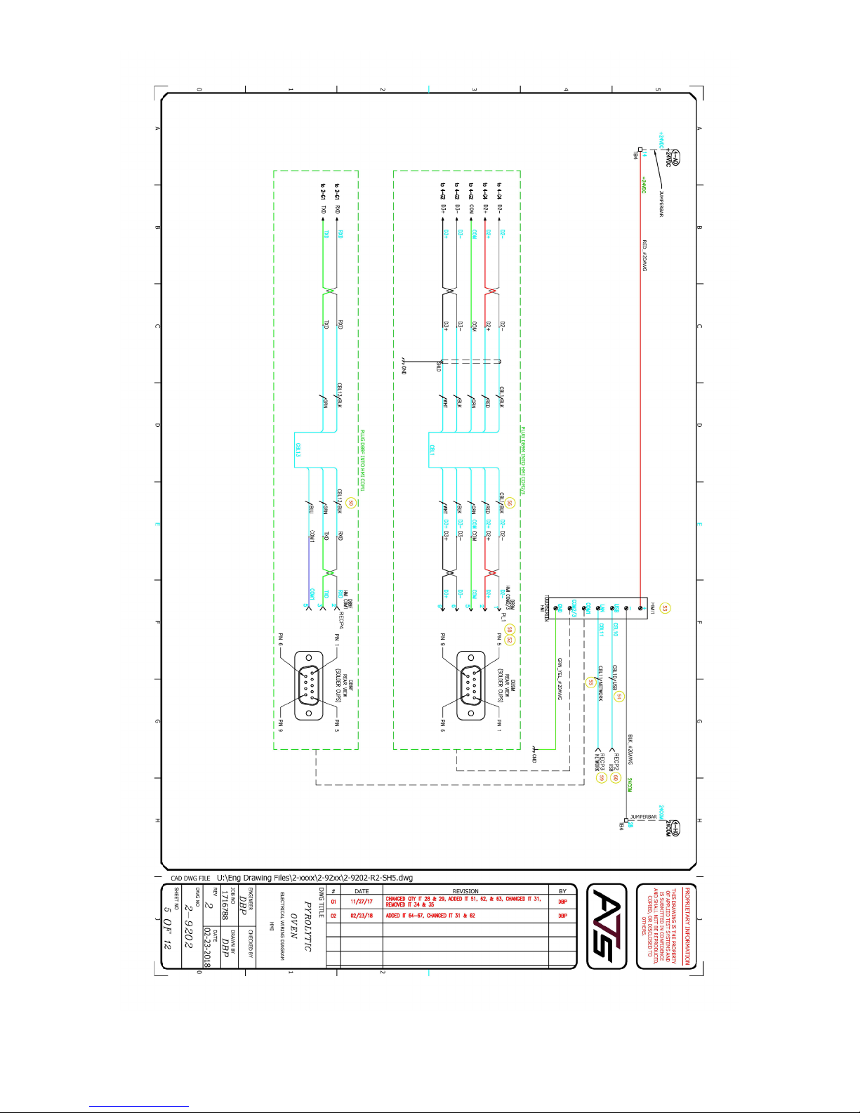
MAN - Pyrolytic Oven - REV: Original | Appendix B: Wiring Diagrams42
Page 48
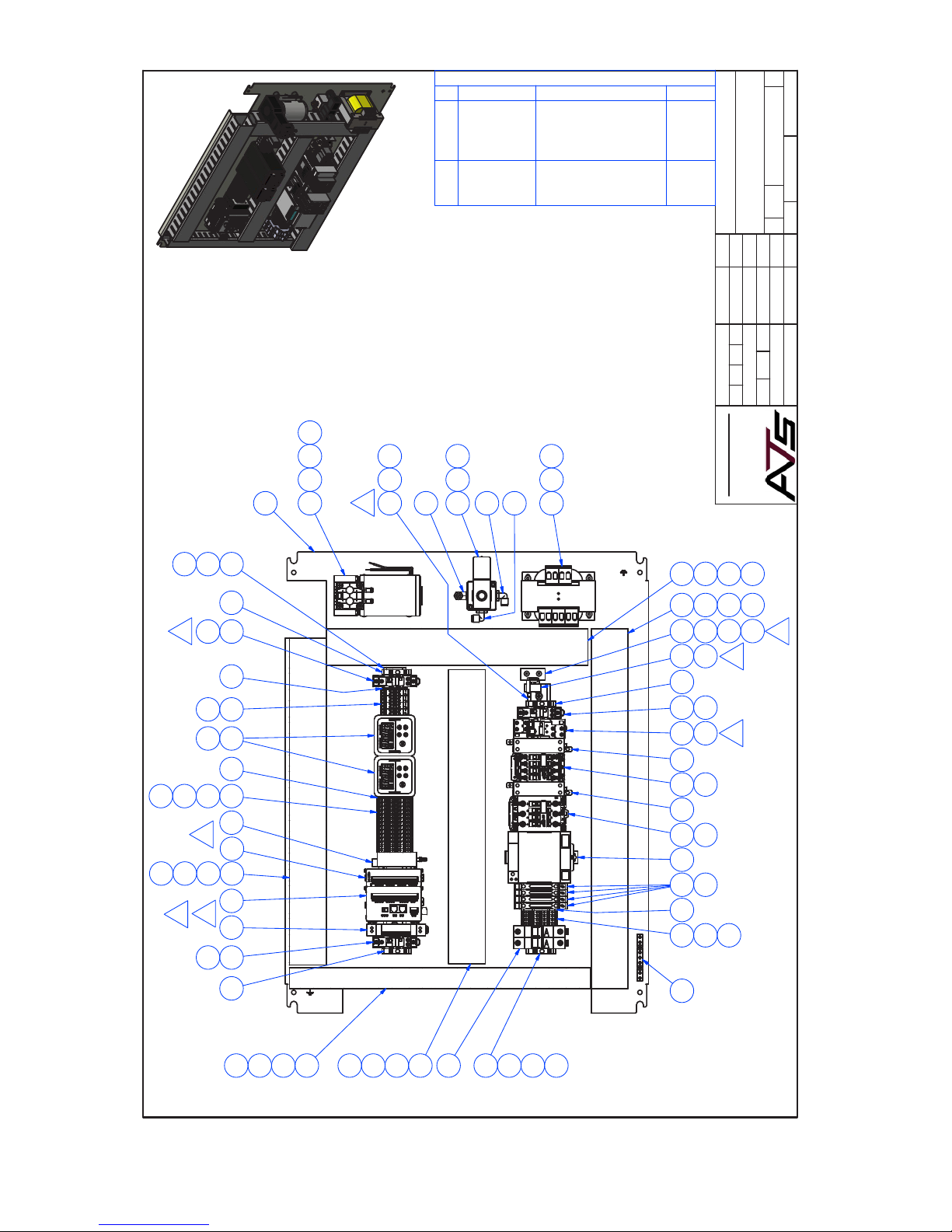
U:\Eng Drawing Files\2-xxxx\2-93xx\2-9308.dwg
R
E
R
E
1
2
A
D
V
1
1
2
/
7
2
2
/
7
V
T
E
2
/
0
1
7
2
/
0
1
8
C
S
I
T
R
H
O
N
S
I
O
I
D
C
A
H
N
A
C
R
E
O
M
A
A
G
H
N
R
E
O
M
Y
E
S
C
R
P
I
N
T
O
I
7
T
E
Q
G
T
I
D
D
E
A
G
H
N
V
I
E
D
T
I
D
D
T
I
E
D
V
I
E
D
4
&
T
I
Y
.
.
5
7
5
.
-
9
2
T
I
.
D
5
5
4
T
3
&
.
6
0
6
.
-
6
2
8
2
&
2
1
,
,
.
5
5
9
T
8
&
.
R
A
T
O
H
U
B
D
P
B
D
P
APPLIED TEST SYSTEMS
3/13/2017
DRAWN
DBP
MACHINING TOLERANCES
UNLESS OTHERWISE SPECIFIED
2
REV
6
OF
1
SHEET
2-9308
DWG NO
3-15281
N.H.A.
PYROLYTIC CLEANING OVEN
ELECTRICAL PANEL ASSEMBLY
REFERENCE
1:4
B
SIZE
TITLE
APPROVED
.X
±.015
.XX
±.010
.XXX
±.005
DECIMAL
SCALE
QA
MFG
ATS P/N
ORDER NO
2-9308
17-15746
±1/32
OVER 18
±1/64
UP TO 18
ANGLES ±1/2°
SURFACE FINISH 63 MICRO INCH
BREAK CORNERS 1/64 MAX RADIUS
FRACTION
47
51
50
43
23
24 26 43
27
42
49
820
1
4
7
3
14
55
56
2
28 42 49
41
25
MTR2
CR5
TB5
40
SOL2
CR4CB1 TB1
CR6
1812
16
17
19
66
2
63
31
35
45
46
INST5
INST4
2
1
2
PWS1 CR3 SSR3CR2SSR2 PS1
4
F
U
3
F
U
2
F
U
1
F
U
1 44
40
32
T1
29
43
8
4
64
5
10
6 21
52 10
9
18
57
4
7
CR1 PWS3 INST1 TB4 INST2 INST3
YSTEMS
OF APPLIED TEST S
THIS DRAWING IS THE PROPERTY
AND SHALL NOT BE REPRODUCED,
PROPRIETARY INFORMATION
AND IS SUBMITTED IN CONFIDENCE
COPIED, OR DISCLOSED TO OTHERS.
34
45
46
33
45
46
48
60
61
2
62
2
7
2
65
15
FRONT
11
13
17
19
SCALE 1 / 4
8
37
38
45
46
MAN - Pyrolytic Oven - REV: Original | Appendix B: Wiring Diagrams 43
39 12
8
28
42
22
30
36
45
46
49
Page 49

Appendix C: Image Glossary
Figure A.1 - ATS Sample Data Tag ........................................................................................................................... 1
Figure C.1 - Pyrolytic Oven Front .............................................................................................................................6
Figure C.2 - Pyrolytic Oven (Rear View) ..................................................................................................................7
Figure D.1 - Oxidizer Pipe ........................................................................................................................................16
Figure E.1 - Pyrolytic Oven Software Screen Map ...................................................................................................17
Figure E.2 - Main Screen..........................................................................................................................................18
Figure E.5 - O State Status Bar ..............................................................................................................................19
Figure E.3 - Main Screen, Alarm State .....................................................................................................................19
Figure E.4 - Main Screen, Delay Start State ............................................................................................................19
Figure E.6 - Oxidizer Preheat State Status Bar ........................................................................................................19
Figure E.7 - Oven Soak State Status Bar .................................................................................................................20
Figure E.9 - Cool Down State Status Bar .................................................................................................................20
Figure E.11 - Delay State Status Bar ........................................................................................................................20
Figure E.8 - Run Cycle State Status Bar ..................................................................................................................20
Figure E.10 - Cycle Finished State Status Bar .........................................................................................................20
Figure E.12 - View Screen ........................................................................................................................................21
Figure E.13 - Language Screen ...............................................................................................................................22
Figure E.14 - Settings Screen ..................................................................................................................................23
Figure E.15 - Manual Screen....................................................................................................................................24
Figure H.1 - Pop-Up Menu .......................................................................................................................................35
Figure H.2 - Second Pop-Up Window ......................................................................................................................36
Figure H.3 - disk_a_1 ...............................................................................................................................................36
MAN - Pyrolytic Oven - REV: Original | Appendix C: Image Glossary44
 Loading...