

Page 1

MANUAL
MTL381 Remote Expander
MTM800 FUG / MTM5400
© ATS Elektronik GmbH
Manual version 1.04
Page 2

All information in this manual has been compiled after careful investigation, but
cannot be considered to be assured as product property. ATS Elektronik
GmbH is only liable in the scope defined in the sales and delivery terms.
We appreciate any completion or suggestion.
ATS Elektronik GmbH is not liable for missed profits and customer ’s property
disadvantages arising f.e. from failure of the product, from incorrect program
function or data loss, either in case that the system combination chosen by the
customer does not answer his requirements, or if intended results may not be
achieved, provided that compelling legal regulations regarding liability in case
of intention resp. coarse negligence do not counteract these liability limits.
We appreciate any completion or suggestion.
You are only allowed to pass on or copy this manual and to make use of its
contents as well as of the software belonging to this product with written permission of ATS Elektronik GmbH. We reserve the right to make modifications
serving for any technical improvement.
Copyright © 2011-2014 ATS Elektronik GmbH, Wunstorf (Germany)
Operating instructions version 1.04 of November 26, 2014
Wunstorf, November 2014
ATS Elektronik GmbH
Albert-Einstein-Straße 3
D-31515 Wunstorf, Germany
Phone: (+49) 50 31/95 48-0
[email protected]
www.ATSonline.de
DIN EN ISO 9001 TÜV Nord CERT Reg.- No: 08/100/971872.
Page 3

3
Contents
Contents
1 Concerning this Manual..................................................4
1.1 Scope of Supplies...........................................................4
1.2 Intended Use ..................................................................5
1.3 Warranty ......................................................................... 6
1.4 Disposal..........................................................................6
2 MTL381.............................................................................. 7
3 Programming Radio Set.................................................. 8
4 Installation...................................................................... 10
4.1 MTL381-Radio..............................................................11
4.2 MTL381-Head...............................................................11
4.3 Loudspeaker.................................................................12
4.4 Line Out Recorder i. V. ................................................. 13
5 Accessories.................................................................... 15
6 Technical Data................................................................ 17
7 List of Figures................................................................18
Page 4

4 Chapter 1
Concerning this Manual
1.1 Scope of Supplies
1 Concerning this Manual
The installation of the MTL381 Remote Expander is described in
this manual.
ATS products are characterised, among others, by the on-going
development for which reason it is possible that the printed documentation is not always absolutely up-to-date.
NOTE
Read this manual carefully before use.
Retain this manual throughout the entire usage period
of the product for future reference.
NOTE
This manual is addressed to trained service engineers
and specialized radio dealers. Competent knowledge
regarding programming and installation of the radio devices and their functions are taken for granted.
1.1 Scope of Supplies
Before you commence with start-up, please make sure that your
supplies are complete:
1x MTL381-Radio (Art.-No. 93861002)
1x MTL381-Head (Art.-No. 93861003)
1x power supply unit for MTL381-Head (Art.-No.
92220032)
1x 10 pin Y cable (KAS028) (Art.-No. 93861005)
1x connector cable MTL381-H <-> control head
(KAS051) (Art.-No. 93861016)
this manual
ATS Elektronik GmbH reserves the right to change the scope of
supplies without prior notice.
For operation you require the following components which are not
included in the scope of supplies:
Page 5

Chapter 1 5
Concerning this Manual
1.2 Intended Use
Motorola MTM800 FuG Remote TETRA mobile radio set
or
Motorola MTM5400 Remote TETRA mobile radio set
Control head for the radio set
CAT 7 S/FTP Ethernet cable in a 1:1 connector as exten-
sion cable of the required length (max. 1000 metres)
Following accessories – not included in the scope of sup-
plies – are at disposal (comp. 4 "Accessories" on page
13):
Loudspeaker SSN4020B with connection cable
Cable set (KAS27) loudspeaker adapter cable with open
ends to connect an alternative loudspeaker (Art.-No.
93860019)
Cable set (KAS20) with open ends for Line Out Recorder ,
Hook, V ol+/- (Art.-No. 98820010)
1.2 Intended Use
The MTL381 Remote Expander may exclusively be used in
closed rooms in conjunction with the Motorola MTM800 FuG, with
the MTM5400 TETRA vehicle radio set respectively. The MTL381
Remote Expander is not suitable for use outdoors or in rooms
with high humidity or under water .
The components of the MTL381 Remote Expander, the control
head of the radio, transceiver part of the radio and the connection
cable must be installed in the same building. No component of
the system may leave the building.
Page 6
6 Chapter 1
Concerning this Manual
1.3 Warranty
1.3 Warranty
If the device had been bought directly from ATS Elektronik, warranty is in accordance with the legal regulations and the general
terms and conditions. The period of warranty starts with the date
of delivery of ATS Elektronik GmbH. There is no right to claim for
guarantee in case of
operating or programming errors
defects caused by the client
willful damages
improper installation/removal of the operating head.
In case of warranty please send back the defect device to ATS
Elektronik GmbH, accompanied by a copy of the delivery note or
invoice. We will then check whether a warranty claim is justified. If
your claim is rejected, you will receive a cost estimate for repair
resp. an exchange unit. ATS Elektronik GmbH will not pay for any
expenses caused by noncompliance with these warranty regulations. If the device had not been bought from ATS Elektronik, the
respective warranty terms of your supplier will apply.
1.4 Disposal
European Union (EU) Directive on Waste Electrical and Electronic Equipment (WEEE):
Products that are brought onto the market in EU member states
must be marked with a crossed-out waste bin symbol (in individual cases the packaging may be marked). The WEEE Directive
specifies that customers and end users in member states of the
European Union (EU) may not dispose of electronic or electrical
equipment and electronic or electrical accessories in the household waste. Within the EU, please contact the local representative
or the customer service department of the supplier of your equipment. He can give you information regarding the disposal or collection of waste equipment.
Page 7

Chapter 2 7
MTL381
2 MTL381
With the MTL381 Remote Expander the remote operation of the
TETRA radio MTM800 FuG, the MTM5400 respectively, can be
operated at a distance of up to 1000 metres from the radio set. A
CAT 7 S/FTP Ethernet cable is used a connection line in a 1:1
connection with RJ45 plug system.
The MTL381 consists of the components MTL381-Radio and
MTL381-Head. The MTL381-Radio is connected to the radio set
via a short 10 pin Y cable. The MTL381-Head is provided with
power by the 12V/1A power supply unit included in the supplies.
As option a loudspeaker (4 or 8 ohm) can be connected.
Note
Firmware and Codeplug of the radio set and of the control head must fit together .
Attention
Interference possible:
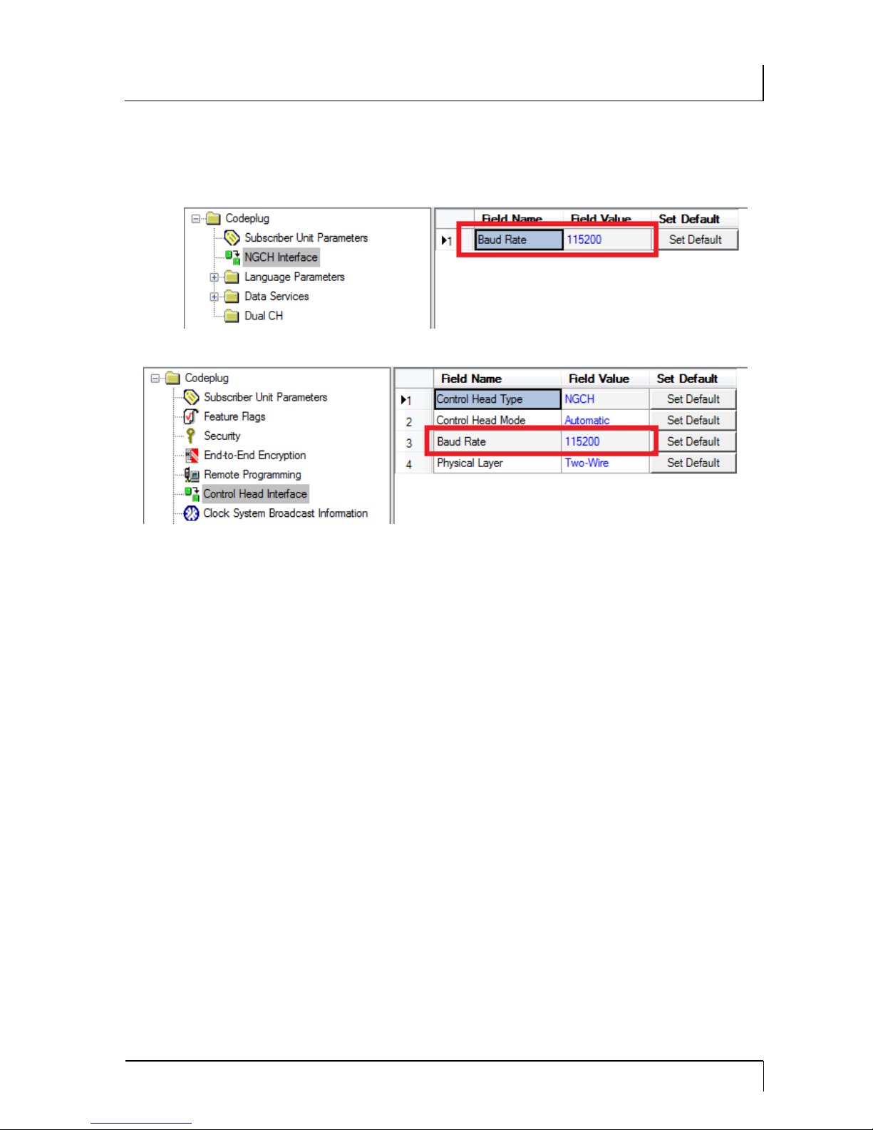
The baud rate of the radio set must be changed to
115200 baud using the Motorola programming software CPS.
You can obtain further information from your radio retailer or ATS Elektronik.
Page 8

8 Chapter 3
Programming Radio Set
3 Programming Radio Set
The baud rate of the radio set and the control head must be
changed to 115200 baud.
Note
This manual is addressed to trained service engineers
and specialized radio dealers. Competent knowledge
regarding programming and installation of the radio devices and their functions are taken for granted.
Note
The following descriptions do not replace the operating
documentation for the Motorola CPS programming
software. They are merely supplementary to it.
Please pay particular attention to the help texts below
the parameters in the CPS.
Motorola CPS For programming of the radios you require:
Programming software Motorola CPS for TETRA radios
Programming cable
Programme the following parameters. You will get the required
data from the system administrator of the TETRA network:
Radio devices ISSI
Group GSSI
National and network code
Frequency
Page 9
Chapter 3 9
Programming Radio Set
Programme the baud rate 115200 baud additionally for control
head and radio set.
Fig. 3-1 Baud rate control head
Fig. 3-2 Baud rate radio set
Page 10
10 Chapter 4
Installation
4 Installation
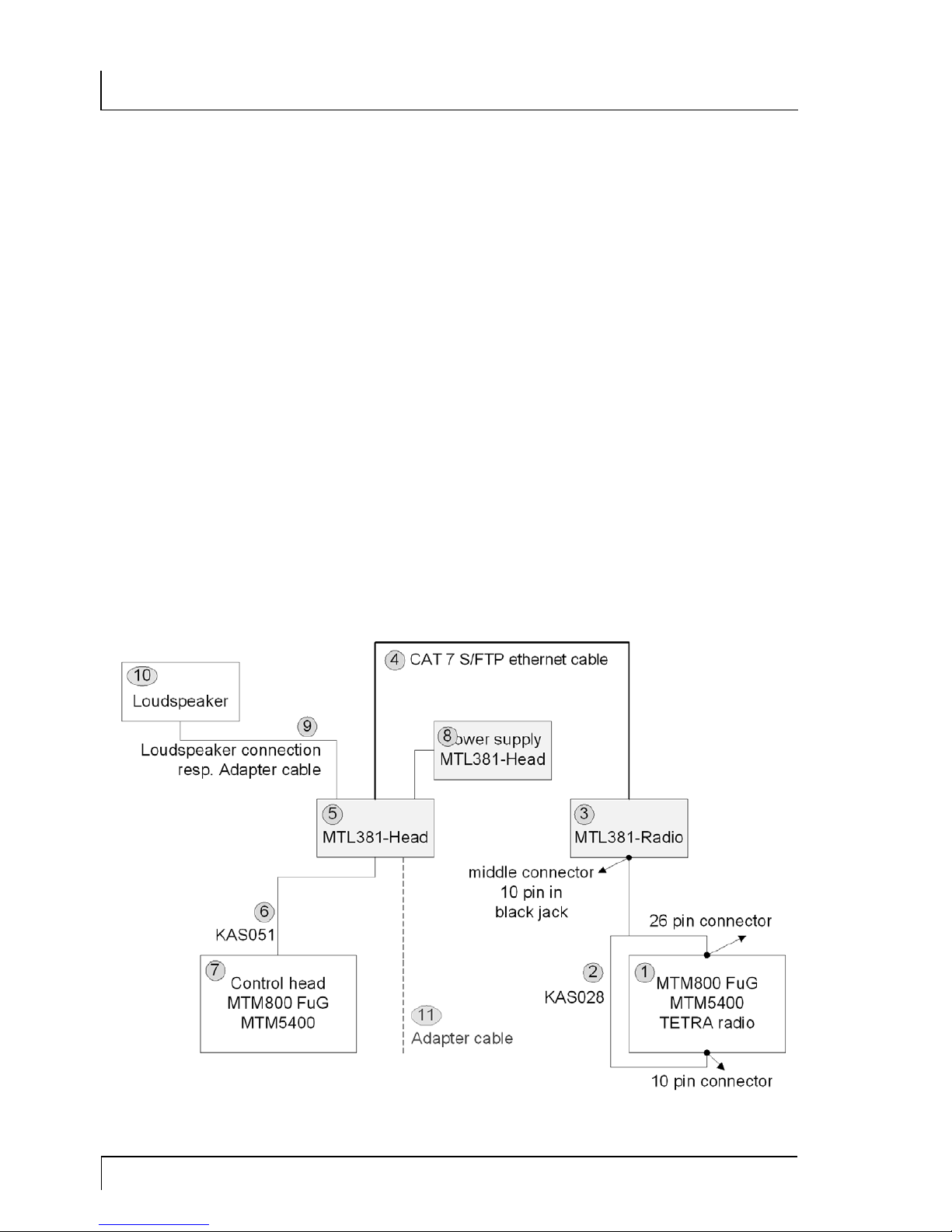
To be able to remove the control head from the TETRA radio
MTM800 FuG the MTM5400 respectively, the following components have to be interconnected:
MTM800 FuG , MTM5400 TETRA radio (1)
10 pin Y cable (KAS028) (2)
MTL381-Radio (3)
CAT 7 S/FTP Ethernet cable in a 1:1 connection (4)
MTL381-Head (5)
10 pin ribbon cable (KAS051) (6)
Control head MTM800 FuG, MTM5400 (7) respectively
Power supply MTL381-Head with connection cable (8)
Loudspeaker connection cable of the SSN4020B, the
loudspeaker adapter cable with open ends (9) resp.
Loudspeaker (10)
Optional adapter cable with open ends for Line Out Re-
corder , Hook, Vol+/- (1 1)
Fig. 4-1 MTL381 System sketch
Page 11
Chapter 4 11
Installation
4.1 MTL381-Radio
4.1 MTL381-Radio
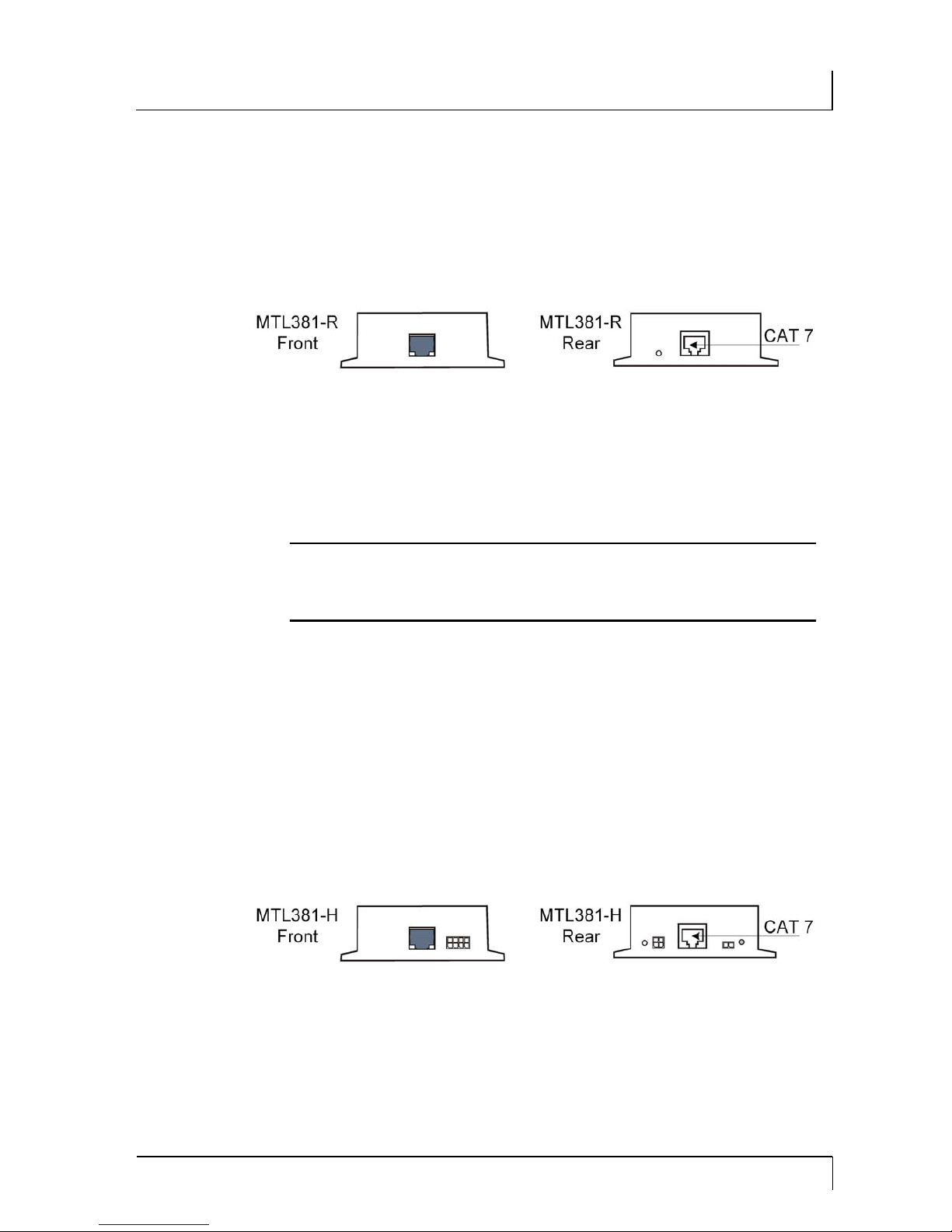
The MTL381-Radio has a outlet for the connection to the radio
set at the front. The RJ45 outlet for the connection of the extension cable and an operation LED is located at the rear .
Fig. 4-2 MTL381-Radio Front and Rear
1. Connect the MTL381-Radio to the radio set at the front
via the 10 pin Y cable.
2. Connect the MTL381-Radio with the MTL381-Head at
the rear via the CAT 7 S/FTP cable.
Attention
Only the radio set may be connected to the black outlet
in front. The operating voltage of 15 V DC may not be
exceeded.
4.2 MTL381-Head
The MTL381-Head has an outlet at the front for the connection to
the control head and an outlet, among others, for the optional
Line Out Recorder. The operation LED, the 'RJ45 outlet for the
extension cable, the outlet for the power supply, the outlet for the
optional loudspeaker and the control knob for the volume are located at the rear.
Fig. 4-3 MTL381-Head Front and Rear
1. Connect the MTL381-Head with the control head at the
front using the 10 pin ribbon cable.
2. The MTL381-Head is connected with the MTL381-Radio
at the rear via the CAT 7 S/FTP cable.
Page 12

12 Chapter 4
Installation
4.3 Loudspeaker
3. Connect power supply to the 4 pin sockets on the left.
Attention
Only the control head may be connected to the black
outlet at the front.
Note
If the control head is separated from the MTL381-Head
and reconnected during on-going operation, a reset at
MTL381-Head has to be carried out. For this purpose
disconnect the power supply at the MTL381-Head for
at least 30 seconds.
Attention
Interruption of operation possible:
The connection between MTL381-Radio and MTL381Head as well as the connection between MTL381-Radio and MTM800 FuG, MTM5400 respectively , may not
be interrupted during on-going operation. The system
no longer reacts after such an interruption.
Note
The system has to be completely disconnected for of at
least 30 seconds before restart after a line interruption.
4.3 Loudspeak er
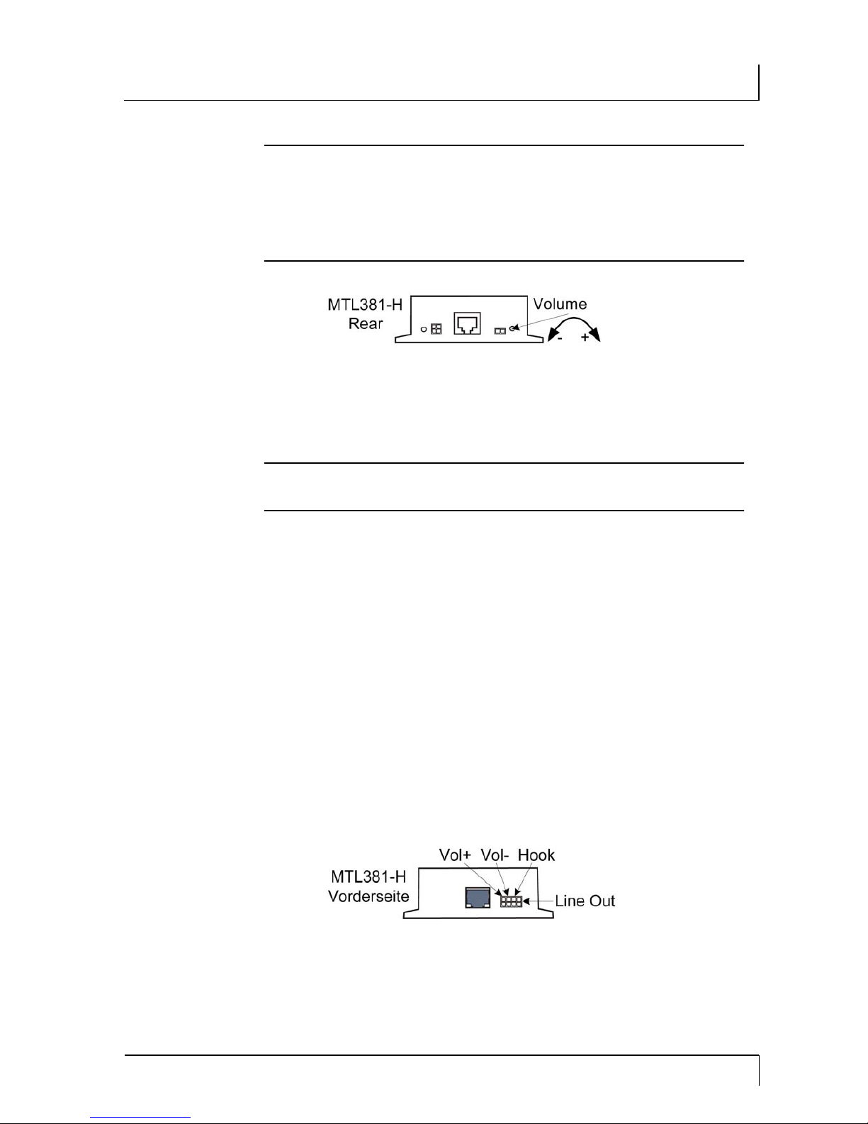
The optional loudspeaker is connected to the 2 pin, horizontal
outlet at the rear of the MTL381-Head. Depending on the length
of the CAT 7 S/FTP Ethernet extension cable and the loudspeaker type, the volume of the loudspeaker has to be adjusted as described in the following. The shorter the connection cable, the
lower the volume of loudspeaker outlet has to be adjusted. The
factory default setting is very low for short connection cables.
Page 13
Chapter 4 13
Installation
4.4 Line Out Recorder i. V.
Attention
Auditory damage possible.
The maximum volume that can be adjusted for very
short connection cables is very loud. Set the volume of
the loudspeaker at "low" (turn the control knob completely to the left).
Fig. 4-4 Volume adjustment MTL381-Head
1. Adjust the volume via the control knob. Turn the control
knob clockwise to increase the volume.
Note
Should loud interference noises be perceived, check
the cable contacts, the local distribution system.
4.4 Line Out R ecorder i. V.
Using the optional adapter cable for the Line Out Recorder the
activities at the control head and the external communications
can be recorded, for instance via the sound card in a PC. For this
purpose a matching plug has to be fitted to the open ends of the
adapter cable.
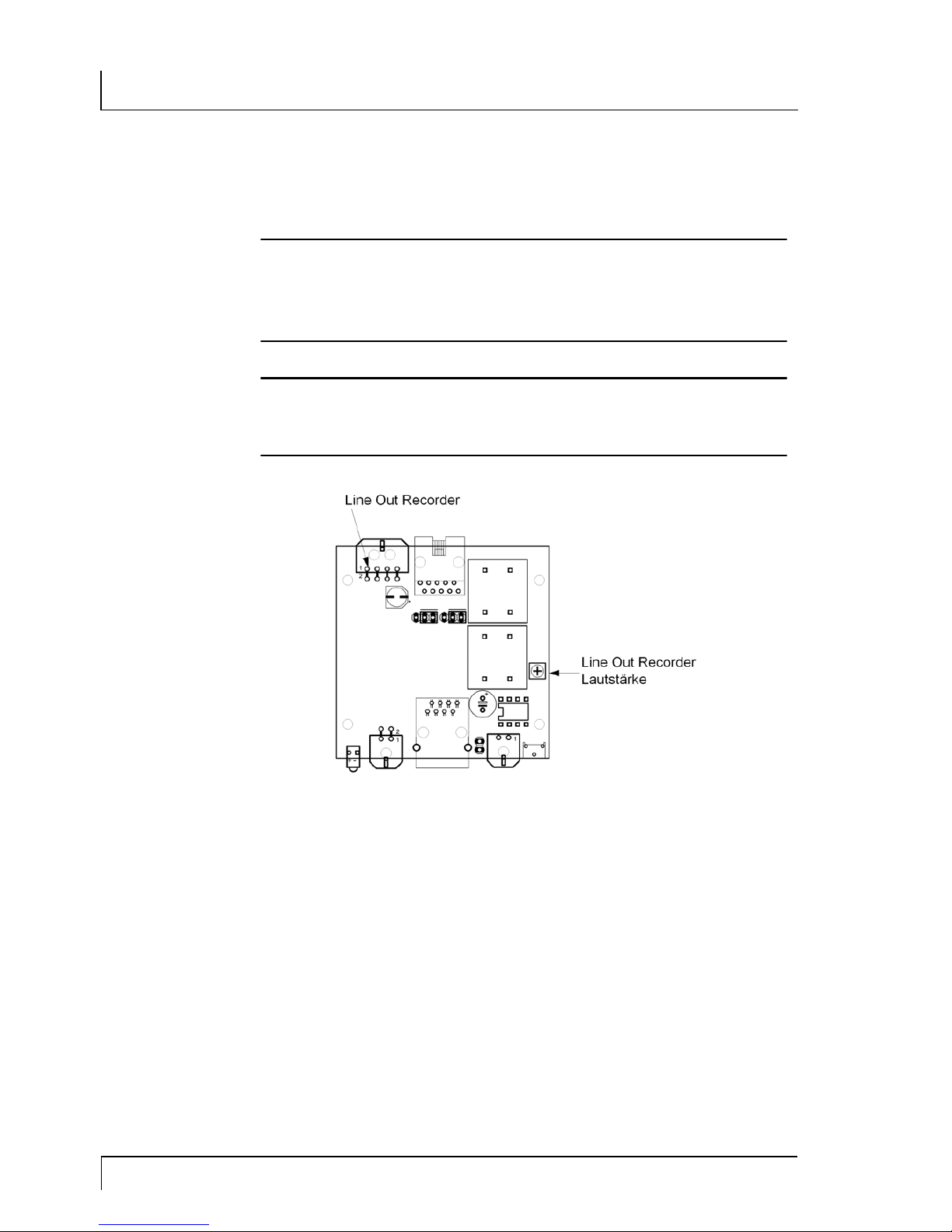
The connections for the Line Out Recorder are located on the 8
pin connection on the extreme right of the MTL381 Head (comp.
labelling on casing). The functions Line Out, Hook and volume
control "V ol+/Vol-" are in preparation.
Fig. 3-5 Connection Line Out Recorder
Depending on the length of the CAT 7 S/FTP Ethernet extension
cable, the volume of the Line Out Recorder has to be adjusted as
Page 14
14 Chapter 4
Installation
4.4 Line Out Recorder i. V.
described in the following. The shorter the connection cable, the
lower the volume of the Line-Out outlet has to be adjusted.
Attention
Auditory damage possible.
The maximum volume that can be adjusted for very
short connection cables is very loud. Set the volume of
the Line-Out Recorder at "low".
Attention
The MTL380-Head may only be opened by trained
specialists. Volume control may only be carried out by
trained specialists.
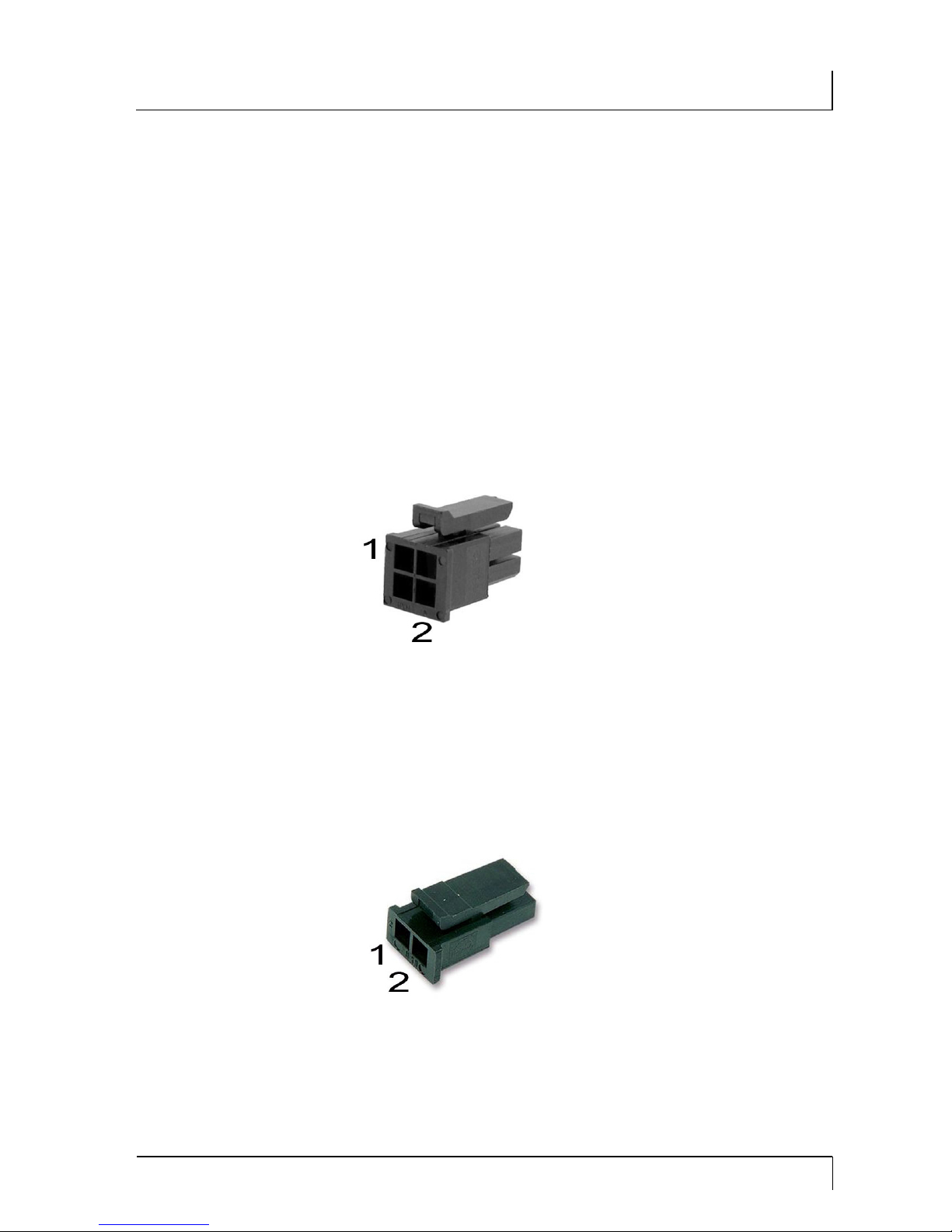
Fig. 4-5 Component layout MTL381-Head
1. Disconnect all the MTL381-Head connections.
2. Open the MTL381-Head casing.
3. Adjust the volume via control knob Line Out Recorder
volume. Turn the control knob clockwise to increase the
volume.
4. Close the casing.
5. Connect the MTL381-Head again.
6. Connect the Line Out Recorder using the 2 pin connector
at the front of the MTL381-Head.
Page 15
Chapter 5 15
Accessories
5 Accessories
You can connect the Motorola loudspeaker, Article No.
SSN4020B directly to the MTL381 using the appertaining Molex
connector. Should you want to connect another loudspeaker, you
have to fit it with a Molex connector .
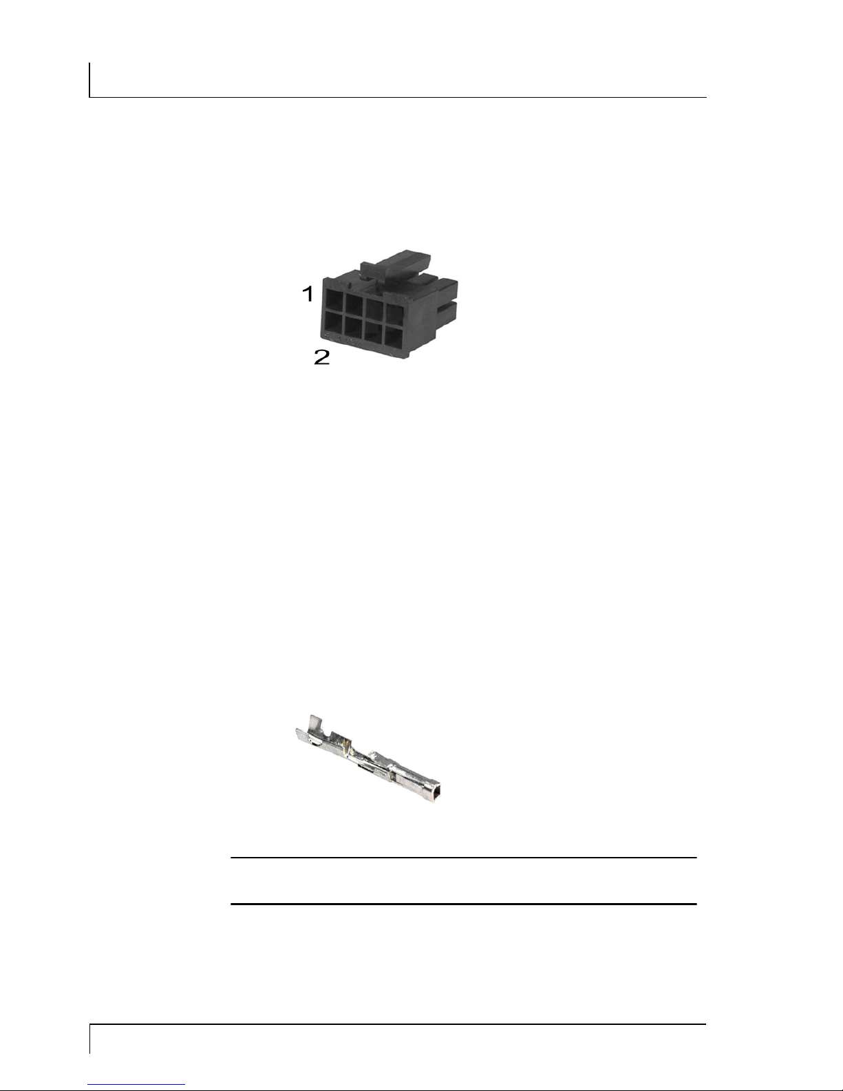
Molex connector
You can use the following Molex connector for the MTL381:
Power supply:
Connector housing 4 pin, Order No. 43025-0400 Molex
Micro Fit
Fig. 5-1 Molex 43025-0400
- 1) +12 V
- 2) GND (ground)
Loudspeaker (max. 1 W on 8 Ohm):
Connector housing 2 pin, Order No. 43645-0200 Molex
Micro Fit
Fig. 5-2 Molex 43645-0200
- 1) Speaker +
- 2) Speaker -
Page 16
16 Chapter 5
Accessories
Line Out Recorder (max. 1 Vss):
Connector housing 8 pin, Order No. 43025-0800 Molex
Micro Fit
Fig. 5-3 Molex 43025-0800
- 1) NF Out
- 2) GND (ground)
- 3) Hook
- 4) GND (ground)
- 5) Vol-
- 6) GND (ground)
- 7) Vol+
- 8) GND (ground)
Crimp contacts
Additional crimp contacts are required for all Molex Micro Fit con-
nector housings.
Crimp contact, Order No. 43030-0007 (20-24 AWG)
Fig. 5-4 Crimp contact 43030-0007
Note
A special crimping tool is required for the crimp con-
tacts.
Page 17

Chapter 6 17
Technical Data
6 T echnical Data
Definition Value
Power Supply MTL381-Radio: supplied by the radio set
MTL381-Head: 12V / 1A DC power supply
Current consumption MTL381-Radio: approx. 37 mA
MTL381-Head: approx. 65 mA
Weight MTL381-Radio: 77 g
MTL381-Head: 89 g
Dimensions MTL381-Radio: 100 x 33 x 65 mm (L x W x H)
MTL381-Head: 100 x 33 x 65 mm (L x W x H)
Ambient temperature -20 - +60°C
Cable Y cable KAS028 - MTL381-R <-> T ransceiver part (ap-
prox.60/30cm)
Cable KAS051 - MTL381-H <-> Remote Head (75 cm)
Line connection up to 1000 m, tested with CAT7 UC900 SS23 S/FTP ca-
ble
Operation LED green LED
Optional loudspeaker 4 or 8 ohm with 1 Watt NF
Optional loudspeaker
connection-adapter cable
Length: max 2 m
Shielding: none
Optional adapter cable
for Line Out Recorder
Length: max. 2 m
Shielding recommended
Radio set MTM800 FuG Remote, MTM5400 Remote respectively ,
tested with Firmware R27.000.7791 (Codeplug 0172)
Tab. 6-1 Technical data
Page 18

18 Chapter 7
List of Figures
7 List of Figures
Fig. 3-1 Baud rate control head................................................9
Fig. 3-2 Baud rate radio set......................................................9
Fig. 4-1 MTL381 System sketch ........................................... 10
Fig. 4-2 MTL381-Radio Front and Rear.................................11
Fig. 4-3 MTL381-Head Front and Rear .................................11
Fig. 4-4 Volume adjustment MTL381-Head.......................... 13
Fig. 3-5 Connection Line Out Recorder................................ 13
Fig. 4-5 Component layout MTL381-Head........................... 14
Fig. 5-1 Molex 43025-0400 ................................................... 15
Fig. 5-2 Molex 43645-0200 ................................................... 15
Fig. 5-3 Molex 43025-0800 ................................................... 16
Fig. 5-4 Crimp contact 43030-0007 ...................................... 16
Page 19

Page 20

 Loading...