

Page 1
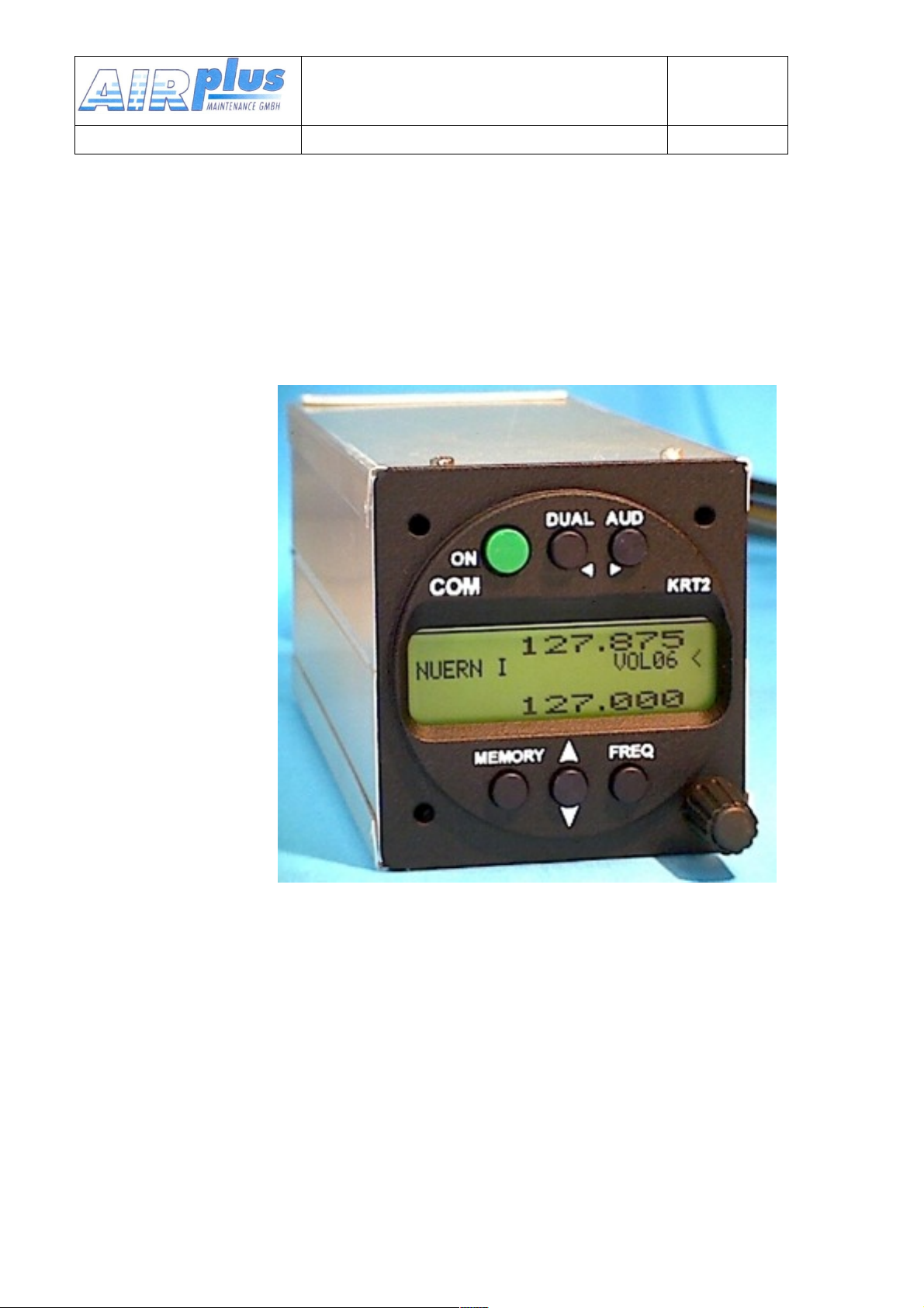
KRT2
User & Installation manual
VHF- Communication Transceiver
Doc.-Nr:
DE-3000-800100e
KRT2 & KRT 2A
Revision 5.0
Software >5.00
VHF Communication
Transceiver
Operation and Installation
P/N 100-( )-( )
Manual
1 of 1
Page 2
Record of Revisions
Revision
Date
Subject
1
06 Juni 2010
Erstausgabe
2
20 Sep 2010
Revision Stecker / Redaktionelle Änderungen
3
05 Feb 2011
Editorial update
4
04 Mai 2012
Cable-harness correction
5
16 Mai 2012
Software advantage for battery indication, error reports
Service-Bulletins have to be inserted in the manual, and entered in
the table.
SB Number
Rev.
No.
Date
Issued
Date
Inserted
Name
Item No.
Product Overview
Basic Version
Introduction of::
• 2 Standard Microphone Inputs
• Auxiliary Audio Input
• DUAL Watch Function
User & Installation manual
VHF- Communication Transceiver
Doc.-Nr:
DE-3000-800100e
KRT2 & KRT 2A
Revision 5.0
Software >5.00
List of Service-Bulletins (SB)
Unit overview
2 of 52
Page 3

User & Installation manual
VHF- Communication Transceiver
Doc.-Nr:
DE-3000-800100e
KRT2 & KRT 2A
Revision 5.0
Software >5.00
3 of 52
Page 4

TABLE OF CONTENTS
User & Installation manual
VHF- Communication Transceiver
Doc.-Nr:
DE-3000-800100e
KRT2 & KRT 2A
Revision 5.0
Software >5.00
......................................................................................................................................GENERAL 6
........................................................................................................................................Symbols 6
...............................................................................................................................Abbreviations 7
.......................................................................................................................................Display 11
................................................................................................................................OPERATION 14
.......................................................................................................................................General 14
.........................................................................................................................SQ -- Squelch 18
...........................................................................................................................MIC – Setup 22
..............................................................................................................................DUAL Watch 24
.........................................................................................................................Self test monitor 27
..........................................................................................................................SET UP - Menu 29
............................................................................................................................Remote Control 30
....................................................................................................................................Installation 31
........................................................................................................................Installation Hints 31
....................................................................................................................................Mounting 32
.........................................................................................................................Customer Service 8
.......................................................................................................KRT2 Transceiver properties 8
.......................................................................................................................CONTROL general 9
.........................................................................................................Control Elements Overview 9
...................................................................................................................ON / OFF Switching 14
...................................................................................................................Frequency Selection 15
....................................................................................................Direct Frequency Selection 15
.......................................................................Frequency Selection from the Favourites List 15
..............................................................................................Storing and Editing Favourites 16
...................................................................................................................AUD – Audio Menu 18
.......................................................................................................................VOL – Volume 18
........................................................................VOX – Intercom Voice Trigger Level Setting 19
................................................................................................TXm – PTT Switch Selection 19
.........................................................................................................INT – Intercom Volume 21
.....................................................................................EXT – External Audio Input Volume 21
.............................................................................DIM – Display Brightness (Batt.-voltage) 21
........................................................................................................CON – Display Contrast 21
.......................................................................................................................SIT – Side tone 21
................................................................................................................Transmitter Operation 26
.....................................................................................................................Optical side tone 27
.......................................................................................................Resetting to factory settings 28
....................................................................................ERASE – Erasing the Favourites List 29
.....................................................................................................................Channel Spacing 30
............................................................................................................Telecommunication Data 31
.......................................................................................................................Scope of delivery 31
.................................................................................Unpacking and Inspecting the Equipment 32
...............................................................................................................Electrical Connections 33
4 of 52
Page 5

........................................................................................................Microphone-Connection 33
User & Installation manual
VHF- Communication Transceiver
Doc.-Nr:
DE-3000-800100e
KRT2 & KRT 2A
Revision 5.0
Software >5.00
.............................................................................................................Earphone Connection 34
..............................................................................................................External Audio Input 34
...................................................................................................................Finally Audio-Setup 35
For gliders 35
....................................................................................................................For motor gliders 35
....................................................................................................................Für Motor planes 35
.........................................................................................................................................Wiring 36
...........................................................................................................................Wire Gauges 36
.................................................................................................Connector Pin-Configuration 36
......................................................................................................................Wiring Diagram 38
................................................................................................................Connection support 40
......................................................................................................................................Antenna 41
..................................................................................................................Antenna Selection 41
................................................................................................Installation Recommendation 41
...................................................................................................................Microphone general 42
..............................................................................................................Post-Installation Check 42
.................................................................................................................................Starting Up 43
................................................................................................................................Accessories 43
....................................................................................................................................Drawings 45
............................................................................................................................Dimensions 45
............................................................................................................Installation Directions 46
........................................................................................................................................ANNEX 47
..................................................................................................Frequency / Channel- schedule 47
............................................................................................................................Technical Data 49
5 of 52
Page 6
1.GENERAL
User & Installation manual
VHF- Communication Transceiver
Doc.-Nr:
DE-3000-800100e
KRT2 & KRT 2A
Revision 5.0
Software >5.00
This manual contains information about the physical, mechanical and
electrical properties as well as a description for the operation and
installation of the VHF airborne transceiver KRT2.
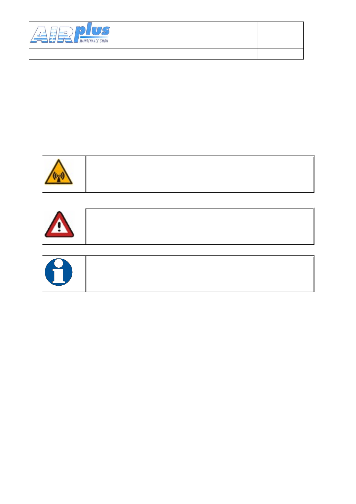
1.1. Symbols
WARNING
Non compliance may cause personnel injury due to
radiation or fire.
CAUTION
Non-compliance may cause damage or incorrect operation
of the transceiver.
INFORMATION
6 of 52
Page 7
1.2. Abbreviations
Abb
Description
Definition
PTT
Push to Talk
Transmitter activation
VOX
Voice operated intercom
Voice level setting fort he activation of
the intercom
INT
Intercom level
Intercom volume level setting
SQ
Squelch
Squelch setting
DIM
Dimming
Display brightness setting
CON
Contrast
Display contrast setting
EXT
External audio input
External Audio input level setting
User & Installation manual
VHF- Communication Transceiver
Doc.-Nr:
DE-3000-800100e
KRT2 & KRT 2A
Revision 5.0
Software >5.00
7 of 52
Page 8
1.3. Customer Service
User & Installation manual
VHF- Communication Transceiver
Doc.-Nr:
DE-3000-800100e
KRT2 & KRT 2A
Revision 5.0
Software >5.00
In order to process returned units most expeditiously, please fill in the
form xxxxxxxxxxxxxxxxxxx to be found under AIRplus Service at
www.airplus24.com.
Suggestions which will improve this manual are very
much appreciated at: www.airplus24.com
Information concerning software updates are available
under AIRplus
Avionics at
www.airplus24.com
1.4. KRT2 Transceiver properties
• VHF airborne transceiver
• Frequency range 118,000 to 136,975 MHz
• Channel spacing 8,33/25 kHz (2278 channel)
• Fast channel selection
• 4 separate microphone inputs (2 x standard or 2 x dynamics)
• Audio-input for other audio devices
• Installation: Standard panel cut-out (57 mm)
• 100 user definable frequencies with up to 8 character
designators
Continuous transmissions will be turned off after 2 minutes.
(Stuck mic function).
8 of 52
Page 9
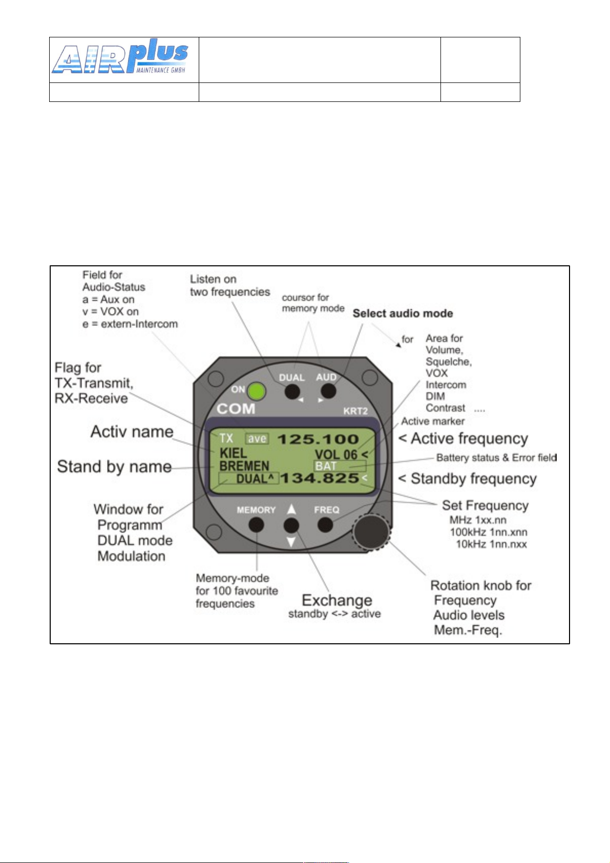
2.CONTROL general
User & Installation manual
VHF- Communication Transceiver
Doc.-Nr:
DE-3000-800100e
KRT2 & KRT 2A
Revision 5.0
Software >5.00
2.1. Control Elements Overview
9 of 52
Page 10
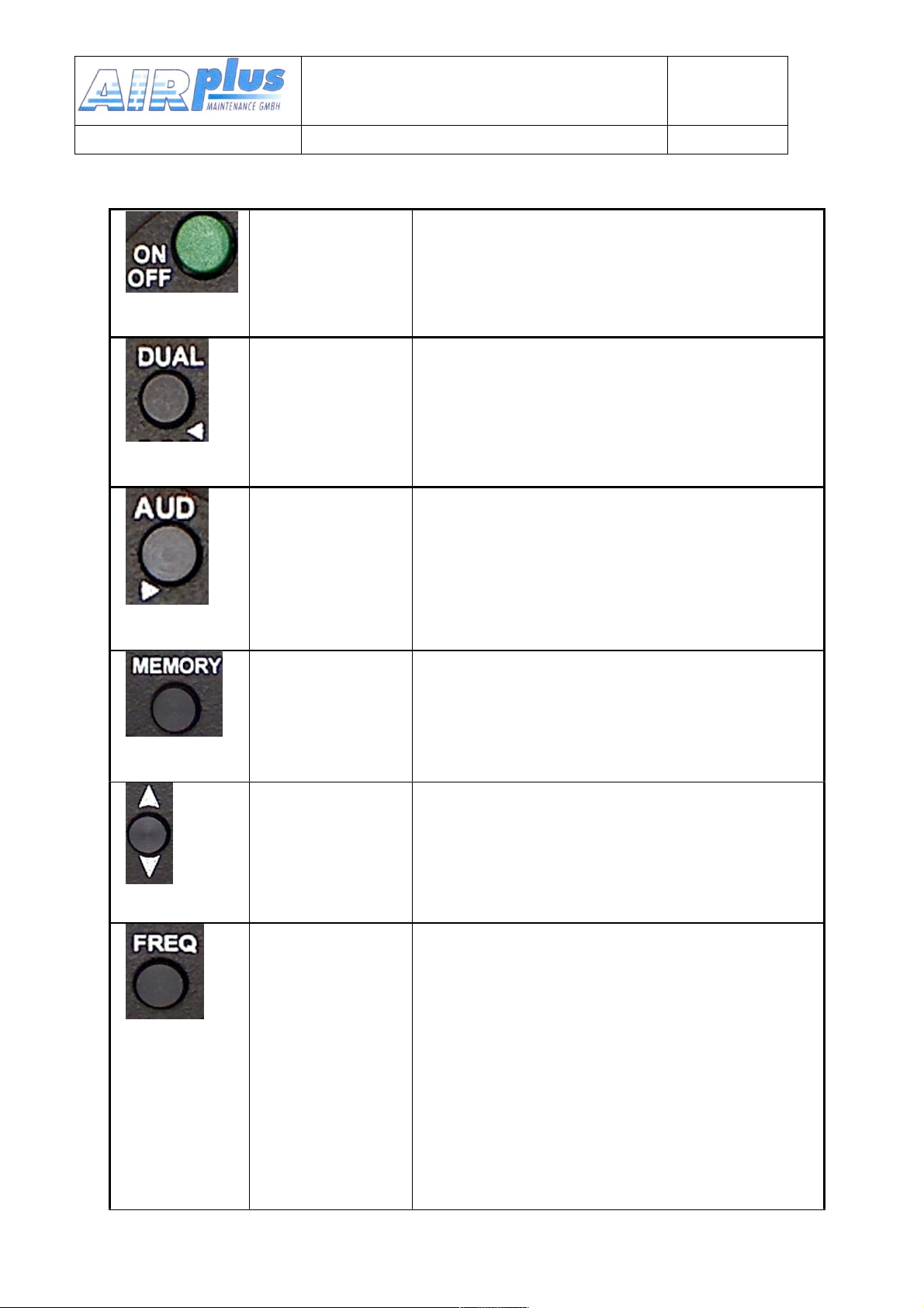
ON / OFF
Self-locking switch
DUAL
WATCH
1. Scanning between the Active and
Standby frequencies
2. Positioning cursor to the left when
programming the station designator
AUDIO
SELECT
1. Stepping through the audio menus
VOL SQ VOX TX INT EXT DIM CON
SIT and MIC
2. Positioning cursor to the right when
programming the station designator
FAVOURITES
1. Frequency and designator selection
from the favourites list
2. Programming of favourites (frequency
and designator)
EXCHANGE
Exchange
of the
Active and Standby
frequencies
FREQUENCY
1. Selection of the frequency range
MHz, 100kHz, 10kHz
2. Toggles
between
frequency
and
designator
when
programming
the favourites
User & Installation manual
VHF- Communication Transceiver
Doc.-Nr:
DE-3000-800100e
KRT2 & KRT 2A
Revision 5.0
Software >5.00
10 of 52
Page 11
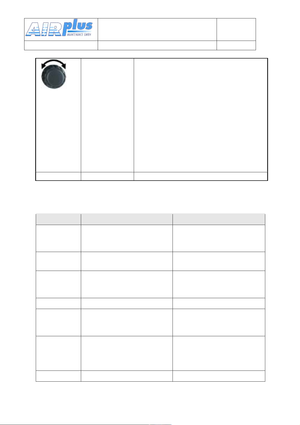
TURNING
KNOB
Sets all variable values in any menu
1. Volume setting of headsets and
speakers
2. MHz/kHz selection of the standby
frequency in 3 different ranges
3. Favourite selection
4. Alpha character selection when
programming favourites
5. Change of microphone settings
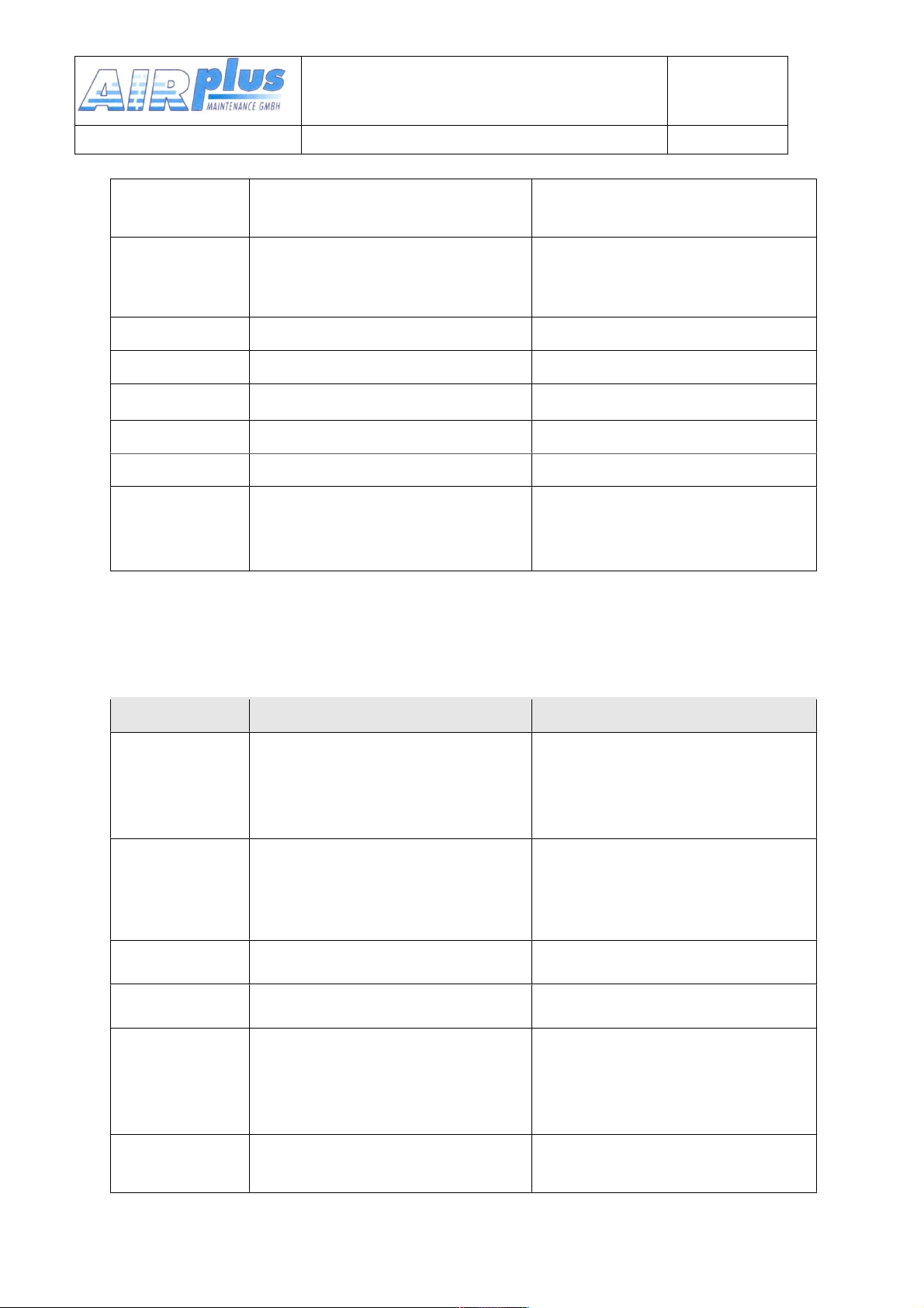
2.2. Display
Indication
Meaning
Remarks
RX
Reception
RX is displayed during
reception with a squelch
value of 02 or more
TX
Transmission
Transmitter operates
normally
Te
Transmitter was turned off
automatically after 2 min
continuous operation
125.100
Active frequency
KIEL
Active frequency station
designator
Displayed when frequency
and designator is stored in
the favourite list
VOL ……
Receiver volume level
(default after a certain time
delay)
When AUD was pressed
the corresponding Audio
Menu item and setting is
displayed
SQ
Squelch
User & Installation manual
VHF- Communication Transceiver
Doc.-Nr:
DE-3000-800100e
KRT2 & KRT 2A
Revision 5.0
Software >5.00
11 of 52
Page 12
VOX
Voice operated intercom
DIM
Display brightness
CON
Display contrast
INT
Intercom - Volume
EXT
Volume of external devices
TX**
PTT button selection
Left/Right/Both
SIDE
Side tone
During transmitter operation
BREMEN
Stand
by frequency station
designator
Displayed when frequency
and designator is stored in
the favourite list
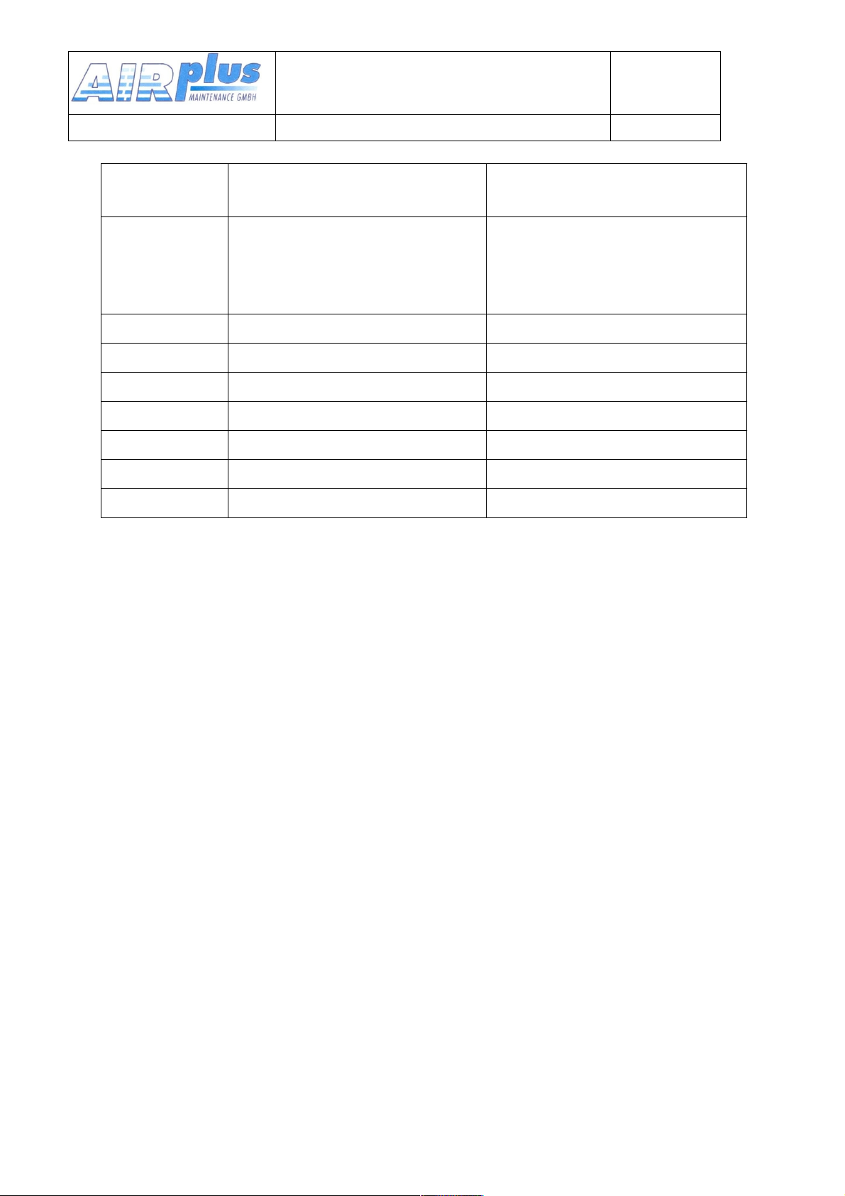
Display
Meaning
Remark
DUAL
Active frequency AND
Standby Frequency are
monitored simultaneously
DUAL function is
deactivated by frequency
change or by pressing the
DUAL button again
[03]
(MEMORY)
Favourite list index
(0-99)
When frequency and
designator are stored at
this index they are
displayed
125.100 upper
Active - frequency
134.825 lower
Standby - frequency
<
The pointer indicates what
the turning knob will change
1)VOL SQ VOX…..etc
2)Standby frequency
Arrow is positioned in
correspondence to the
button pressed
( AUD or FREQ)
BAT
Supply voltage is low
<10,5V
Battery low or
Battery/Generator faulty
User & Installation manual
VHF- Communication Transceiver
Doc.-Nr:
DE-3000-800100e
KRT2 & KRT 2A
Revision 5.0
Software >5.00
12 of 52
Page 13
Er_ANT
Antenna error
Bad antenna match
a v e
Status of certain Audio
menu functions
a = AUX. Input active
v = VOX active
e = external Intercom
switch active
Er_PLL
Internal error, no transmission
Return the transceiver for
maintenance
Er_ADC
Internal error,
Return the transceiver for
maintenance
Er_FPA
Internal error; unit not usable
Return the transceiver for
maintenance
Er_I2C
Internal error; unit not usable
Return the transceiver for
maintenance
Er_si53
Internal error; unit not usable
Return the transceiver for
maintenance
Er_D10
Internal error; reception corrupt
Return the transceiver for
maintenance
Key_Block
Internal error; unit not usable
Return the transceiver for
maintenance
User & Installation manual
VHF- Communication Transceiver
Doc.-Nr:
DE-3000-800100e
KRT2 & KRT 2A
Revision 5.0
Software >5.00
13 of 52
Page 14
3.OPERATION
User & Installation manual
VHF- Communication Transceiver
Doc.-Nr:
DE-3000-800100e
KRT2 & KRT 2A
Revision 5.0
Software >5.00
3.1. General
There is a normal operating mode in which the turning knob always is
connected to the volume (VOL). The normal operating mode can be left by
pressing the AUD, FREQ or MEMORY button.
When not in the normal mode and there is no pilot action for more than 10
seconds the unit returns to the normal mode.
3.2. ON / OFF Switching
ON / OFF switching is achieved with a self-locking switch.
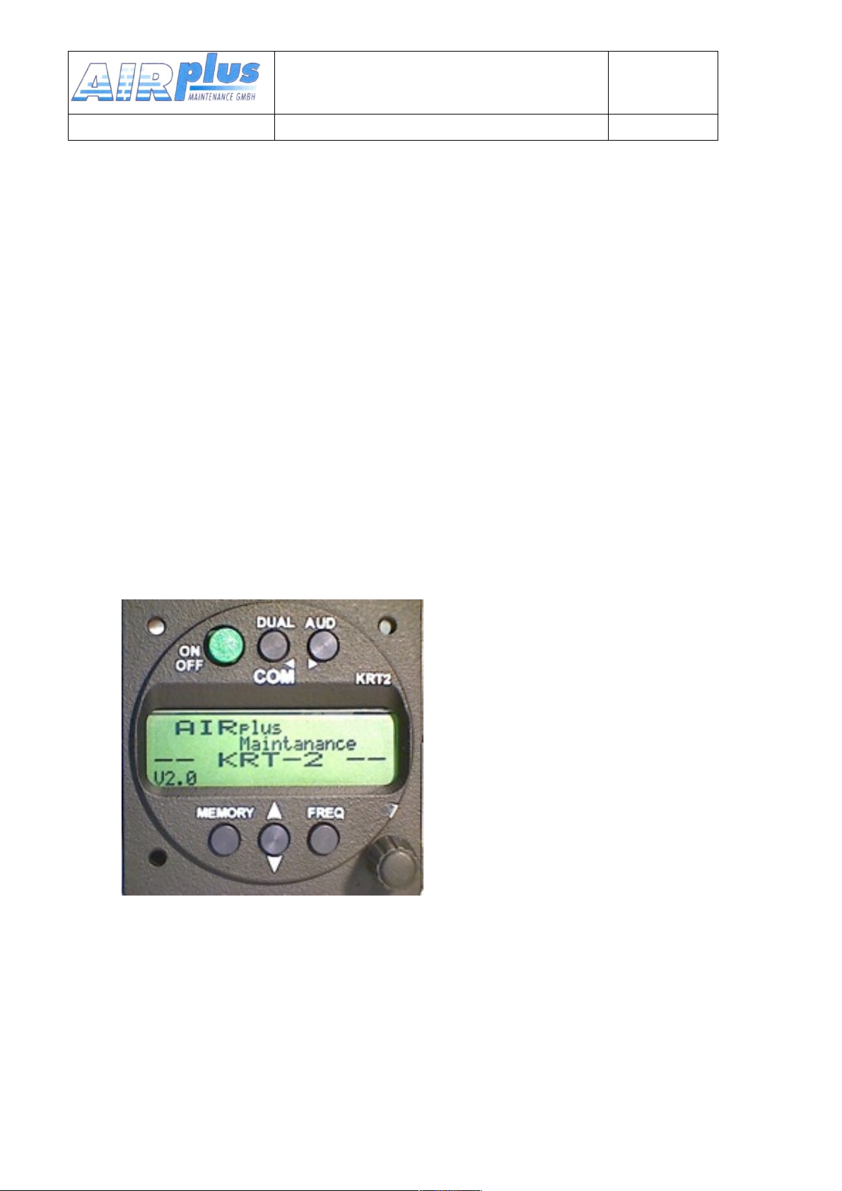
After power up the following display will show up:
Device-name
KRT2
Software Version e.g.
V2.0
Gerätename
KRT2
Software Version e.g.
V2.0
(example)
The unit then starts in the normal operating mode using and displaying the
data last used.
14 of 52
Page 15
3.3. Frequency Selection
User & Installation manual
VHF- Communication Transceiver
Doc.-Nr:
DE-3000-800100e
KRT2 & KRT 2A
Revision 5.0
Software >5.00
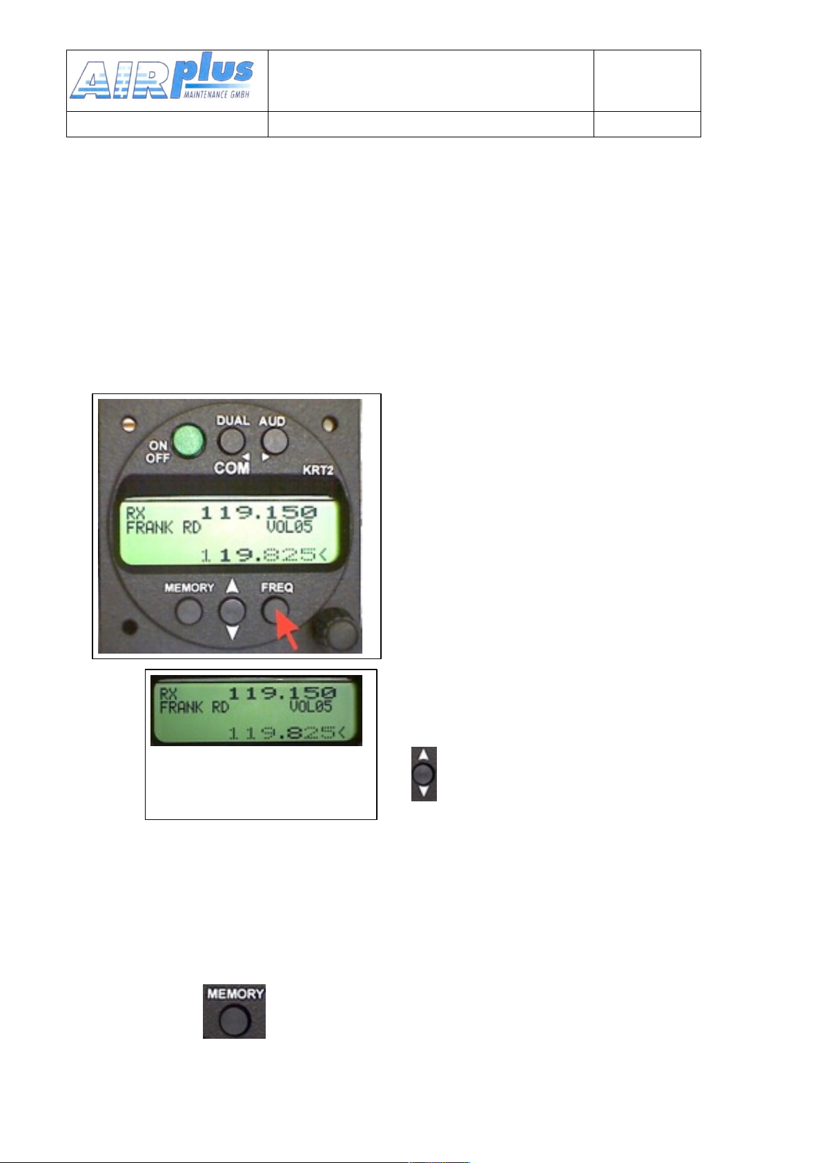
There are two different frequency selection methods:
• Direct Input
• Selection from the favourite list (index 0-99)
3.3.1.Direct Frequency Selection
The Standby-Frequency is set with the
tuning knob in 3 different ranges. The
selected range is highlighted and can
be changed with the FREQ button.
Frequency ranges are: 1xx.nnn
1nn.xnn
1nn.nxx
Press the FREQ button once or
several times until the desired
frequency range is highlighted.
When the pointer is not next to the
Standby Frequency window, it will be
repositioned with the first pressing of
the FREQ button.
Exchanges the Active and
Standby frequencies.
When the Exchange button was not pressed, the Standby frequency
display will return to its normal appearance after 20 seconds.
3.3.2. Frequency Selection from the Favourites List
By pressing and operating the turning knob a specific favourite list
position can be accessed [xx] (xx = index 0 … 99). When frequency and
station designator have been defined, they will be displayed in the Standby
15 of 52
Page 16
and station designator windows.
User & Installation manual
VHF- Communication Transceiver
Doc.-Nr:
DE-3000-800100e
KRT2 & KRT 2A
Revision 5.0
Software >5.00
The favourite list designators can be sorted in alphabetic order (see 3.3.3).
Exchanges the Active and Standby frequencies.
The selection procedure can be terminated with either the AUD or FREQ
buttons. Without pressing any of these buttons the unit will return to its
normal operating mode after 20 seconds.
3.3.3. Storing and Editing Favourites
Any displayed Standby Frequency can be given a designator and both can
be stored together as favourites in the favourite list. Both, the frequency
and designator of a favourite can be edited.
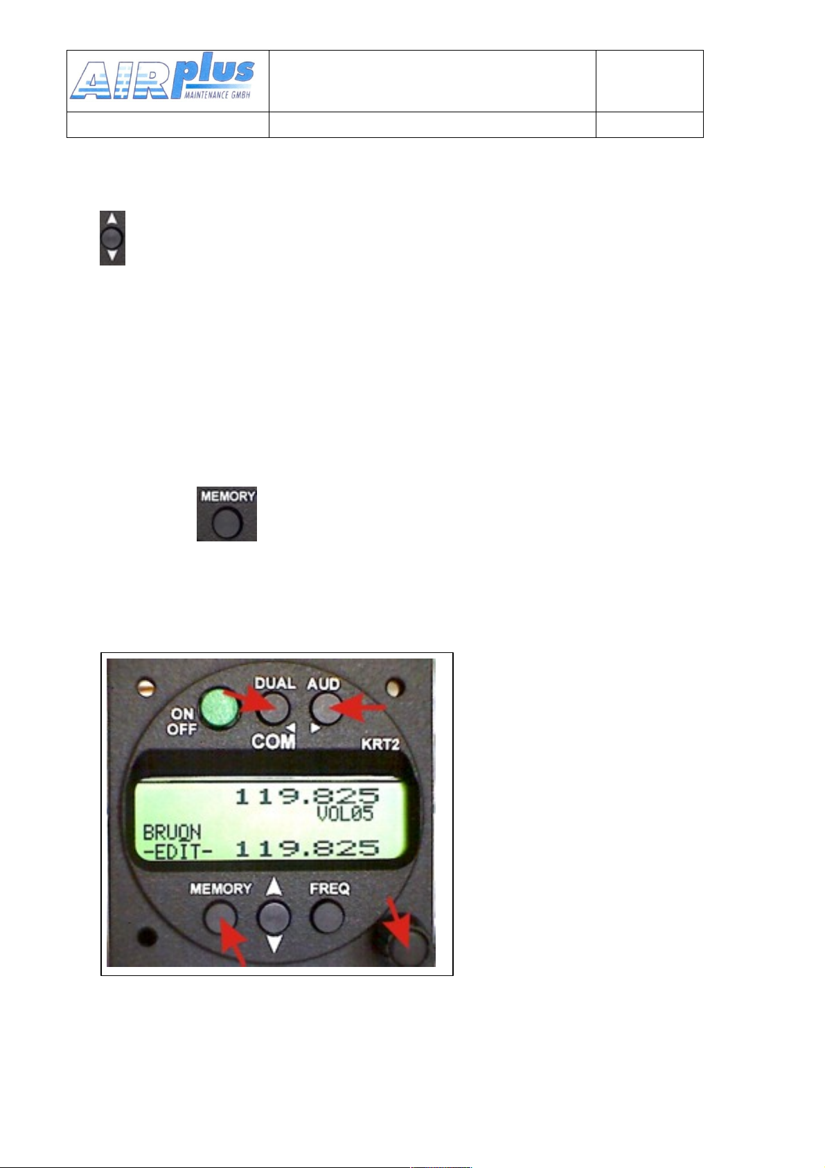
First press button and by means oft he turning knob go to the
desired favourite list position which may be empty or the favourite to be
edited (index [00 …99]).
Press the MEMORY button a second time and „–EDIT--„ will show up in the
program window.
In the designator window a
blinking cursor will show up
under the most left character.
The turning knob selects the
desired character.
The AUD button positions the
curser one character to the
right. The DUAL button
positions the cursor one
character to the left and
simultaneously erases this
character.
The station designator can consist of maximum 8 characters.
Press the FREQ button and follow the normal direct input procedure to edit
the frequency.
16 of 52
Page 17
Press the MEMORY button in order to go to the station designator window
User & Installation manual
VHF- Communication Transceiver
Doc.-Nr:
DE-3000-800100e
KRT2 & KRT 2A
Revision 5.0
Software >5.00
for editing he designator if required
.
Pressing MEMORY again terminates editing and SAVE? will show up.
SAVE? is available for 20 seconds and must be acknowledged by the
button. No acknowledgement within 20 seconds results in the termination of
the storing procedure.
When the button was pressed SORT? will show up.
SORT? is available for 20 seconds and must be acknowledged by .
When sorting was acknowledged with the button, all 99 favourites will
sorted in alphabetical order which can take several minutes.
During the sort procedure „RUN nn“ is displayed in the program window,
with nn being the running index.
When the MEMORY button is pressed during the time when SORT? is
displayed the sorting procedure will not start and storing and editing is
terminated. The transceiver then resumes the normal operating mode.
When the MEMORY button is pressed during the time when „RUNnn“ is
displayed the sorting procedure is terminated. The favourite list then is
sorted partially only and the transceiver resumes the normal operating
mode.
Further favourites can be stored or edited by following the normal input
procedure.
For time saving purposes it is recommended to initiate the sorting
procedure after the last favourite has been saved or edited.
17 of 52
Page 18
3.4. AUD – Audio Menu
User & Installation manual
VHF- Communication Transceiver
Doc.-Nr:
DE-3000-800100e
KRT2 & KRT 2A
Revision 5.0
Software >5.00
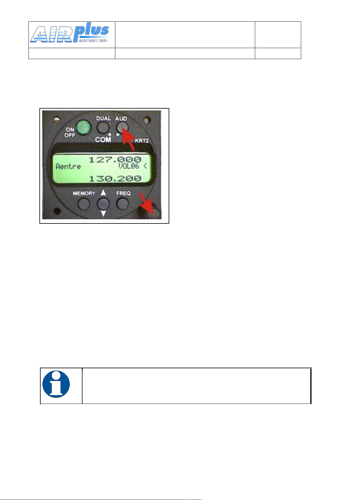
Any action in the Audio Menu
requires the pointer (<) to be next
to the Audio menu window (see
picture). When the pointer is next
to the Standby frequency window,
the pointer can be repositioned by
pressing the AUD button once.
VOLnn is the Audio menu default
display. No action on any control for
more than 10 seconds will result in
the VOLnn display.
Audio Menu items can be accessed in the following order by repeatedly
pressing the AUD button.
VOL (default) SQ VOX TXm** INT EXT DIM CON SIT MIC
Audio menu items to right of the above list are more seldomly used than
the left ones.
3.4.1.VOL – Volume
Turning the turning knob changes the receiver
volume. VOLnn
Range: 01 - 16
Die VOL setting only concerns the receiver and not the
intercom system. Intercom volume values are set in the INT
audio menu.
.
3.4.2. SQ -- Squelch
Pressing the AUD button once enables the turning knob to change the
squelch level values.
18 of 52
Page 19
SQnn
User & Installation manual
VHF- Communication Transceiver
Doc.-Nr:
DE-3000-800100e
KRT2 & KRT 2A
Revision 5.0
Software >5.00
Value range: 01 – 10
The Squelch setting is depending on several factors.
For engine driven airplanes an initial setting of 05-08 is recommended.
Gliders may need a lower setting. The lower the Squelch level value the
higher is the input sensitivity. A high sensitivity setting is susceptible to
noise from other sources like ignition strobe-lights etc.
Standard SQ-level is 05 ... 08. Higher setting may
suppress strong input signals. Squelch does not influence
the intercom system.
3.4.3.VOX – Intercom Voice Trigger Level Setting
Pressing the AUD button twice enables the turning knob to change the voice
level which triggers the intercom.
The intercom voice trigger level must be set to such a value which
prevents that normal cockpit noise can be heard in the earphones. The
intercom system shall only be activated when talking at a normal
voice level into the microphone.
The higher the trigger level the louder the voice must be in order to
trigger the intercom system.
VOX on condition is indicated by flag “v”.
VOXnn Range: 01 –
10
In case of extreme cockpit noise or uncompensated microphones the VOX
system can be deactivated by selecting VOX: 01. When VOX is
deactivated, the intercom can only be used by means of intercom
switches.
3.4.4.TXm – PTT Switch Selection
Pressing the AUD button three times enables the turning knob to select
certain PTT switches. In addition when one of both PTT switches is disabled
(notBoth) the respective microphone channel is disabled during trans-
missions.
TXm** *
19 of 52
- Left / -
Right /
*
**
Page 20

Both
User & Installation manual
VHF- Communication Transceiver
Doc.-Nr:
DE-3000-800100e
KRT2 & KRT 2A
Revision 5.0
Software >5.00
20 of 52
Page 21
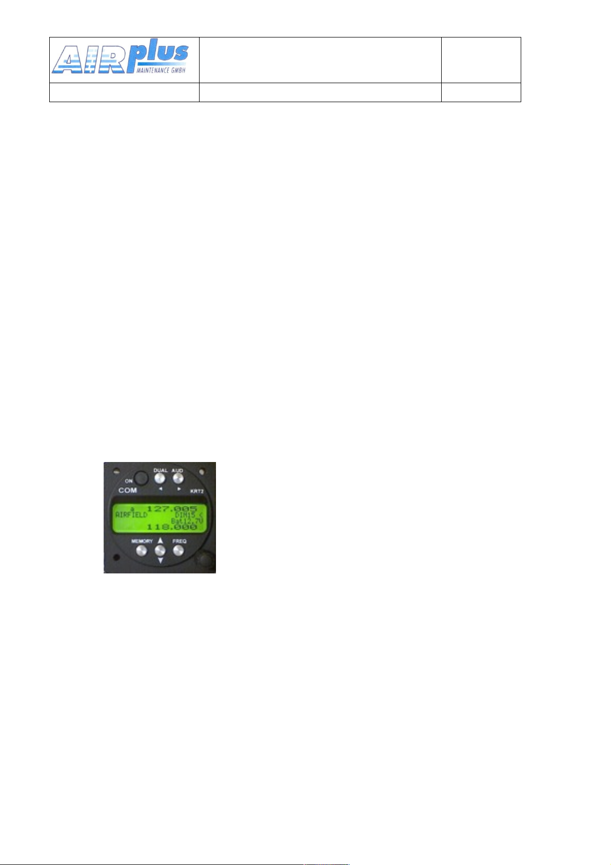
3.4.5.INT – Intercom Volume
User & Installation manual
VHF- Communication Transceiver
Doc.-Nr:
DE-3000-800100e
KRT2 & KRT 2A
Revision 5.0
Software >5.00
Pressing the AUD button four times enables the turning knob to set the
intercom volume.
INTnn Range: 01 - 10
3.4.6.EXT – External Audio Input Volume
Pressing the AUD button five times enables the turning knob to set the
external audio input volume. External audio inputs can be audio alarms, voice
alarms, music etc.
Activation occurs for settings >00 and will be indicated by the flag “a”.
EXTnn Range: 00 - 10
3.4.7.DIM – Display Brightness (Batt.-voltage)
Pressing the AUD button six times enables the turning knob to set the
display brightness.
Display lighting current drain at maximum
brightness is only 10mA. Maximum
brightness is glare free even in darkness and
can be used continuously.
Indication of battery voltage (VDC).
3.4.8.CON – Display Contrast
Pressing the AUD button seven times enables the turning knob to set
the display contrast.
CONnn Range: 01 - 10
3.4.9.SIT – Side tone
Pressing the AUD button eight times enables the turning knob to set
the side tone volume.
SITnn Range: 01 – 10
DIMnn R a n g e : 01 – 10
21 of 52
Page 22
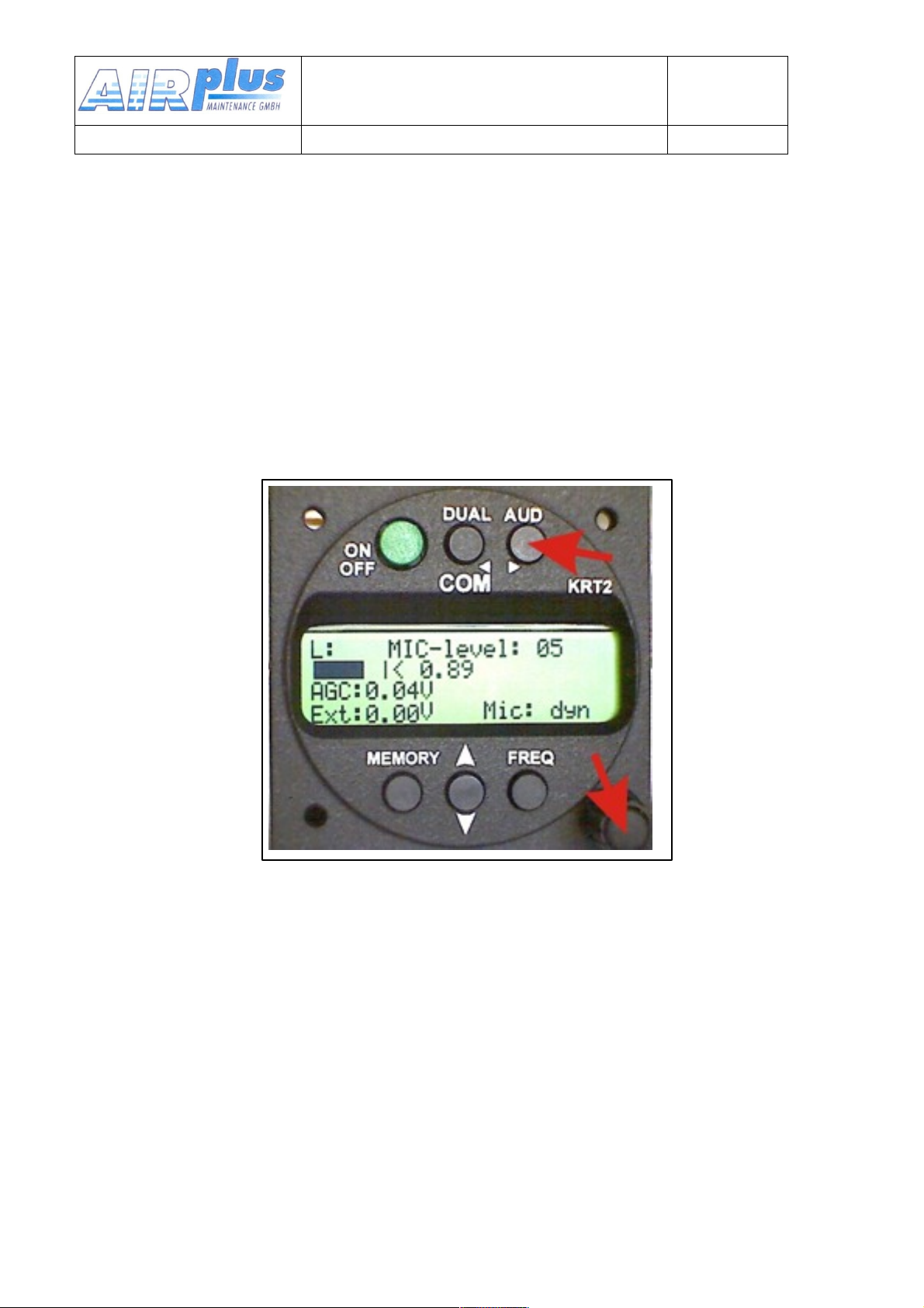
3.4.10.MIC – Setup
User & Installation manual
VHF- Communication Transceiver
Doc.-Nr:
DE-3000-800100e
KRT2 & KRT 2A
Revision 5.0
Software >5.00
Each of the two microphone inputs channels can be configured
individually, which enables different microphone types to be used.
A maximum of two microphones of same type may be connected to each
microphone input channel (see Microphone Connection 5.6.1).
The MIC – Setup is the last item of the Audio menu and can be accessed
by pressing the AUD button nine times.
By pressing the DUAL button repeatedly L, R and AUTO can be selected.
L (R) means left (right) microphone input channel. The AUTO function is
explained later.
By means of the turning knob the displayed microphone input channel
amplifier gain (MIC-level01=lowgain,09=highgain) can be selected
individually. The microphone signal level is dynamically displayed as bar
and as numeric value (from0.00to1.00) in the line below.
The initial MIC-level should be 05, the engine should be running, use a
headset or earphone and speak at a normal voice level to fine-tune the
MIC-level. Whenever a new MIC-level was selected, the dynamic bar
indicator should then be at about 50%.
When the microphone setup menu is left, the new value is stored.
The range of the MIC-level for standard microphones is 01 to 09.
22 of 52
Page 23
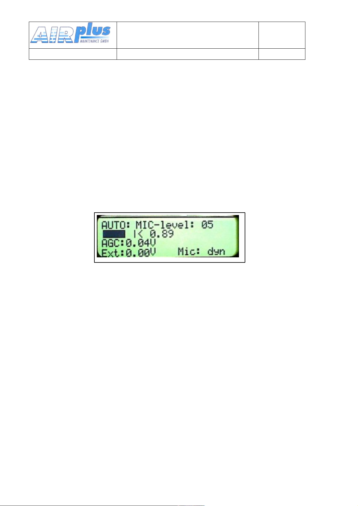
MIC levels 10 and 11 are special settings for low microphone
User & Installation manual
VHF- Communication Transceiver
Doc.-Nr:
DE-3000-800100e
KRT2 & KRT 2A
Revision 5.0
Software >5.00
levels like dynamic micro-phones often used in gliders.
10 is used for non-amplified Electret microphones with a 8 volt
supply voltage.
11 is for dynamic microphones only.
In the AUTO mode every 30 sec. the left microphone impedance
is measured. When using an Electret microphone and a dynamic
microphone is recognized, internal switchover to the dynamic
microphone type and vice will take place. When using a dynamic
microphone and an Electret microphone is recognized, internal
switchover to the Electret microphone type will take place.
Microphone type switch over always affects both microphone
channels.
The present recognized type will be indicated (Mic: dyn/std).
To activate the recognition instantly leave AUTO and set back to
AUTO.
For the std-part the previous individual setup is stored when the
menu was leaving.
The MIC submenu is left by pressing the AUD button.
Additional indications
Additional indications for test purposes:
AGC: ..... HF receiver Automatic Gain Control
Ext: ..... External audio input voltage
Mic: dyn or Mic: std
Indicates, which microphone type was selected either by the user or
recognized in the AUTO mode.
23 of 52
Page 24
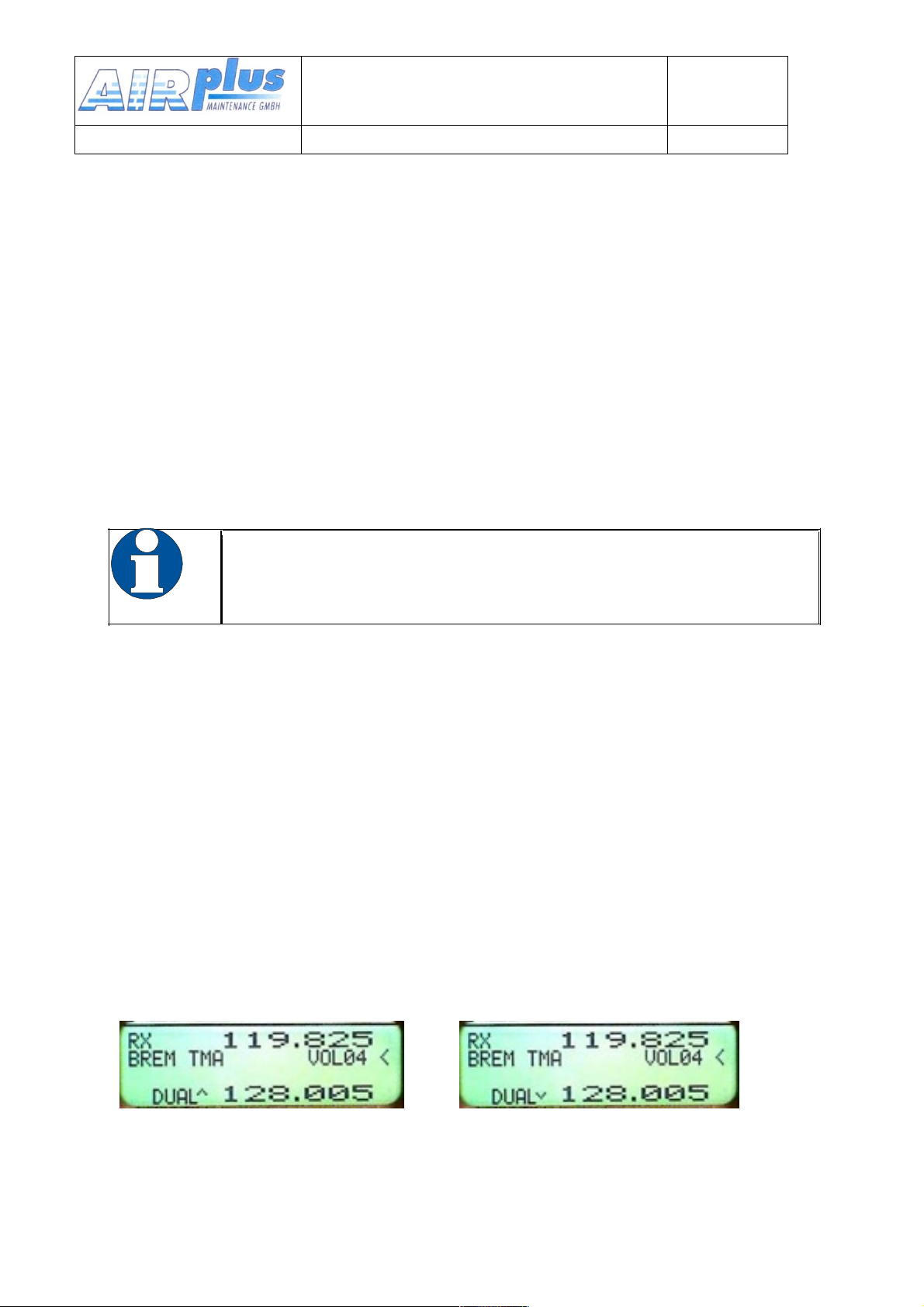
3.5. DUAL Watch
User & Installation manual
VHF- Communication Transceiver
Doc.-Nr:
DE-3000-800100e
KRT2 & KRT 2A
Revision 5.0
Software >5.00
Because the communication transceiver KRT2 contains only one
receiver, DUAL watch is achieved by alternating between the Active and
Standby frequencies.
The DUAL button activates and deactivates the dual watch function.
Deactivation also can take place by pressing either the FREQ or
MEMORY buttons.
The frequencies to be watched should be selected prior to the DUAL
watch selection.
Scanning of frequencies is only possible when differentiating between
radio noise and radio transmissions. This can be achieved with the
squelch system set to a value of 02 or higher.
There must be radio noise suppression in order to
recognize reception. SQ must be 02 or higher.
When DUAL watch is activated, “DUAL“ is displayed on the lowest line.
The pointer next to the DUAL display indicates the frequency on which
there is reception.
The Active frequency always has priority, so the receiver remains on the
Active frequency as long as there is reception on the Active frequency.
When there is no reception on both the Active frequency and the Standby
frequency the receiver scans both frequencies 5 times per second.
When there is reception on the Standby frequency the receiver stays on
the Standby frequency, however it switches to the Active frequency every
2 seconds for 0.3 seconds. When reception is detected on the Active
frequency the receiver stays on the Active frequency.
The pointer next to the DUAL display indicates on which frequency
there is reception.
A c t i v e f r e q u e n c y r e c e p t i o n
Standbyfrequencyreception
24 of 52
Page 25

Standby and Active frequencies can be exchanged when in the DUAL
User & Installation manual
VHF- Communication Transceiver
Doc.-Nr:
DE-3000-800100e
KRT2 & KRT 2A
Revision 5.0
Software >5.00
mode. The transmitter operates on the Active frequency only.
Summary:
• Select the Standby frequency to be watched additionally.
• With the AUD button and turning knob set SQnn to 02 or higher.
• With the DUAL button activate the DUAL watch function.
• When there is no reception on both the Active frequency and the
Standby frequency the receiver scans both frequencies 5 times per
second.
• When scanning the Active frequency always has priority.
• Deactivate the DUAL watch function with the DUAL or FREQ or
MEMORY buttons.
25 of 52
Page 26
3.6. Transmitter Operation
User & Installation manual
VHF- Communication Transceiver
Doc.-Nr:
DE-3000-800100e
KRT2 & KRT 2A
Revision 5.0
Software >5.00
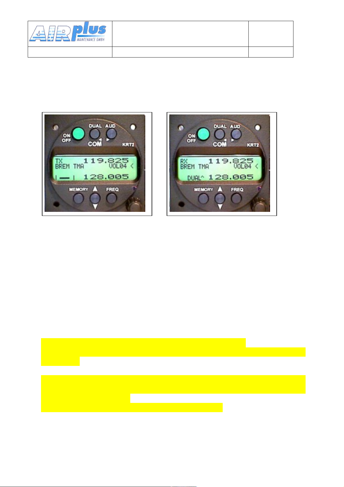
The unit transmits on the active frequency (upper line) as
long as a PTT (press to talk) switch is pressed.
Transmission Reception
„TX“ indicates normal transmitter operation.
In the lower left corner of the display the carrier modulation is dynamically
displayed. It corresponds to the side tone which is not available on gliders
when no earphones are in use.
In order to avoid the blocking of the frequency by unintentional long
transmissions (stuck microphone) the transmitter is switched off after two
minutes and the display changes from „TX“ to „Te“. To resume
transmission the PPT switch first must be released and then be pressed
again.
While transition the external audio input will be turned off.
The microphone selection is dependant from the pre-setting at the TXm-
activation.
The differential speaker output will be turned off to prevent an audio
feedback to the microphone. The speaker also will be disabled if the
intercom (VOX) is active.
The output for the head set will carry the side tone.
26 of 52
Page 27
3.7. Self test monitor
User & Installation manual
VHF- Communication Transceiver
Doc.-Nr:
DE-3000-800100e
KRT2 & KRT 2A
Revision 5.0
Software >5.00
There is a permanent back ground test system active.
The field for battery status & error (see Control Elements Overview) is used
to indicate warnings and in case of hardware failure, different error reports.
The warnings are:
BAT low battery voltage (becomes active < 10,5V)
At transmission
A-match bad antenna match or antenna defective.
Also while transmission the TX-flag (left top) can change to
Te Transmission time has exceed (> 2 minutes)
All other reports starting with Er…. Indicating a major hardware failure and
consequently the radio has to be returned to factory.
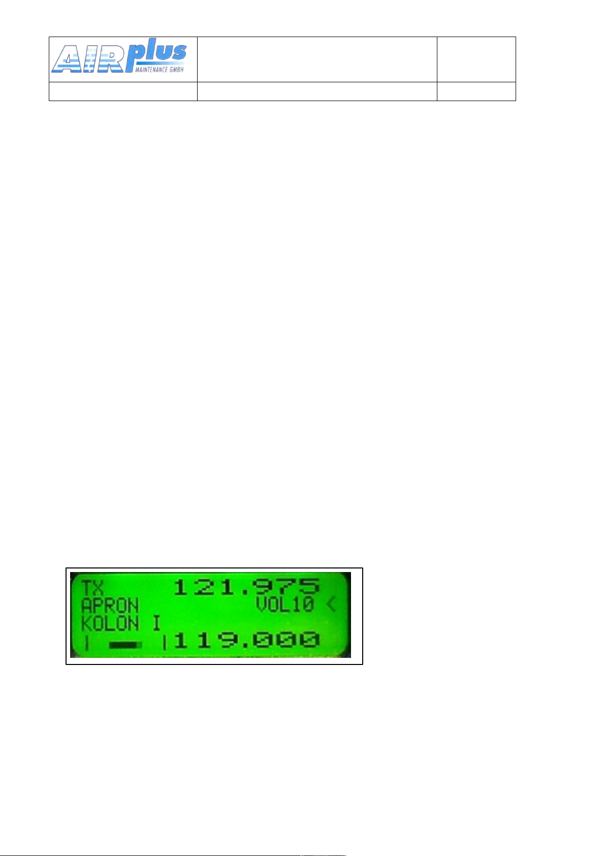
3.7.1.Optical side tone
Especially on glider use, where no headset to get the side tone, it is very
helpful to see the microphone working.
At left lower side, there is a modulation indicator showing the talking
activity. At no modulation it becomes a small dot approximately in the
centre.
Also it indicates a bad antenna matching by getting far out of the centre.
27 of 52
Page 28

3.8. Resetting to factory settings
User & Installation manual
VHF- Communication Transceiver
Doc.-Nr:
DE-3000-800100e
KRT2 & KRT 2A
Revision 5.0
Software >5.00
Returning to the factory settings can only be initiated during power-up.
During power-up the MEMORY and DUAL buttons must be pressed
simultaneously and the display will show “SET DEFAULTS”. When the
buttons are released the resetting to the factory settings takes place.
When resetting is completed “DONE” is displayed.
Resetting tot he factory settings will not change any data in the favourite
list memory.
28 of 52
Page 29
3.9. SET UP - Menu
User & Installation manual
VHF- Communication Transceiver
Doc.-Nr:
DE-3000-800100e
KRT2 & KRT 2A
Revision 5.0
Software >5.00
During power-up the MEMORY buttons must be pressed
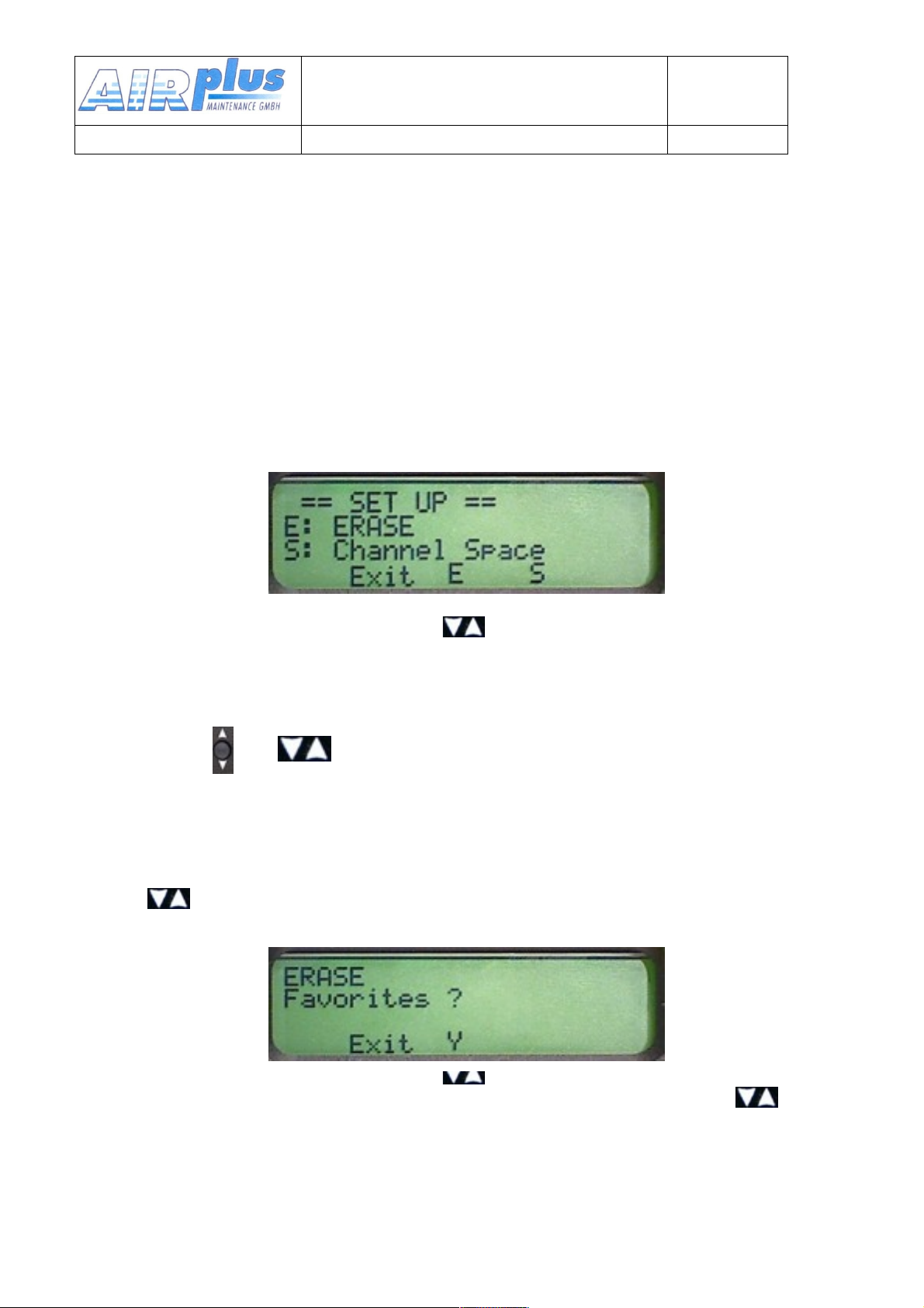
There are two functions within the Set-up menu:
• ERASE – Erasing of the favourites (frequency and designator)
• Channel Spacing – 25kHz / 8,33kHz
Programming of the Set-up is done with the lower 3 buttons. Their
function is described on the display.
MEMORY FREQ
Set-up program exit is with the MEMORY button. The unit remains
powered and the normal operating mode is resumed.
Remark: =
3.9.1.ERASE – Erasing the Favourites List
When in the SET UP – Menu select the “ERASE“ submenu with
the .
MEMORY FREQ
Erasing the favourites (frequency and designator) starts after the
button was pressed again. This procedure may last a few minutes during
which time “ERASING“ is displayed.
All INFO frequencies and designators that were stored on delivery are
29 of 52
Page 30
lost and all favourite index positions (01 to 99) are available to the user.
User & Installation manual
VHF- Communication Transceiver
Doc.-Nr:
DE-3000-800100e
KRT2 & KRT 2A
Revision 5.0
Software >5.00
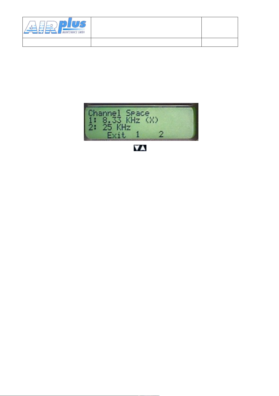
3.9.2.Channel Spacing
When in the SET UP – Menu pressing the MEMORY button will change
into the Channel Space submenu.
MEMORY FREQ
The desired channel spacing then can be selected and the (X)
indicates the actual channel spacing.
4.Remote Control
Tandem-seat airplanes can be equipped with the KRT2RC Remote
Control Unit. The remote control unit is connected to RS232 serial
interface and enables selection of the most common settings like
frequency, volume, squelch, VOX, display contrast and brightness. In
addition the unit has an independent memory for favourites (frequency
and designator).
Transmission error messages are displayed in the error window in the
third line
R_Time = Time-out transmission error
R_ChkS = Checksum error
R_Cmd = Unknown command
R_Char = Data error
R_Freq = Wrong Frequency
The error message disappears when a valid command or a new
frequency has been input, latest however after 5 seconds.
Remote control unit errors do not interfere with the KRT2
transceiver operation.
Data transmissions between the transceiver KRT2 and the remote control
unit is checked once every minute. A “r” in the upper right corner is
30 of 52
Page 31
displayed when there is no malfunction.
Manufacturer
AIRplus Maintenance GmbH
Type
KRT2
EASA Number
P/N 100-90001-00
Power Output
6 W
Frequency:
118,000 – 136,975 MHz
Emission Designator:
6k00A3E für 25khz channel spacing
5k00A3E für 8,33kHz channel spacing
Part Number
Description
KRT2
KRT2 - VHF Transceiver
ZUB2 (3 pcs)
Mounting screw KRT2 - for panels up to
3mm
SSKRT2
Connector
(when no cable set was ordered)
……………………
Operation and Installation Manual
EASA Form 1
User & Installation manual
VHF- Communication Transceiver
Doc.-Nr:
DE-3000-800100e
KRT2 & KRT 2A
Revision 5.0
Software >5.00
5.Installation
5.1. Installation Hints
The following hints should be considered for installation.
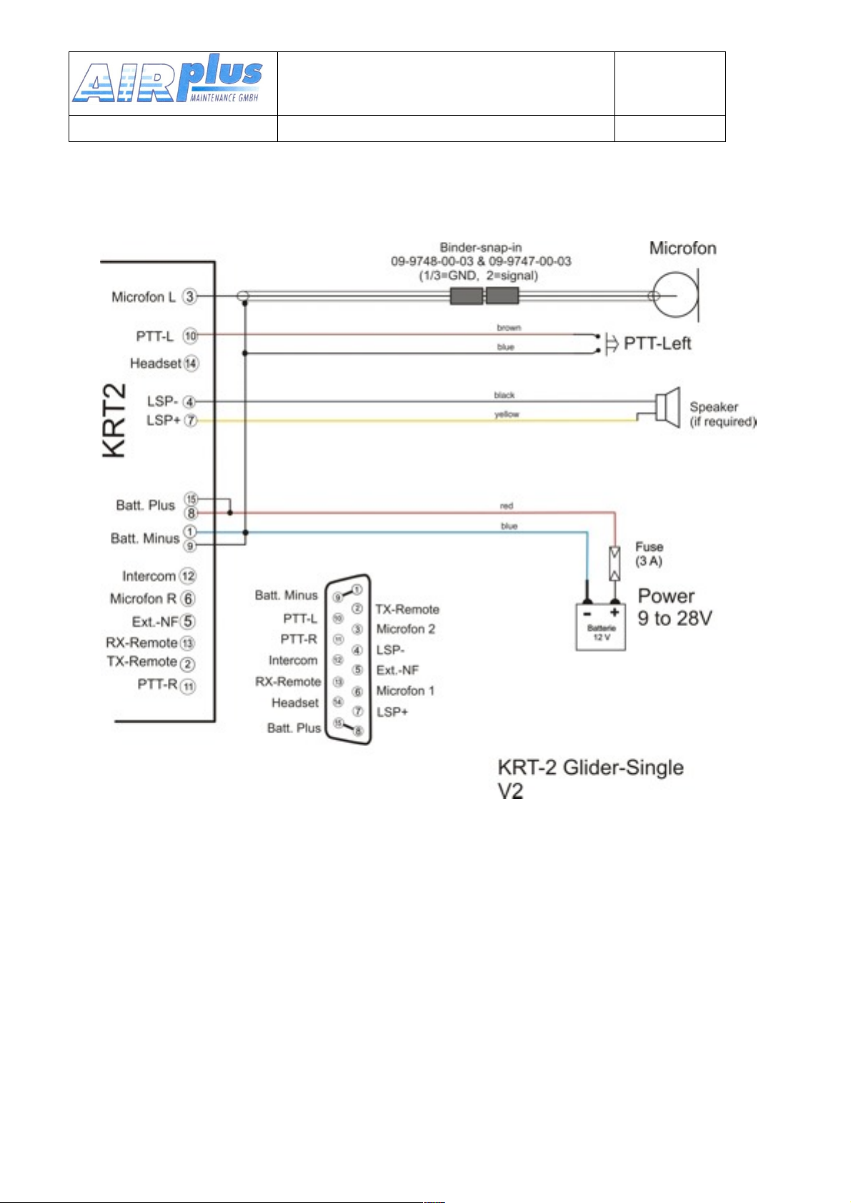
A certified maintenance shop should perform the wiring. For the wiring
diagram refer to chapter 5.7.3
5.2. Telecommunication Data
The following data may be required for the radio station licence.
5.3. Scope of delivery
31 of 52
Page 32
5.4. Unpacking and Inspecting the Equipment
User & Installation manual
VHF- Communication Transceiver
Doc.-Nr:
DE-3000-800100e
KRT2 & KRT 2A
Revision 5.0
Software >5.00
Carefully unpack the equipment. Damages due to transportation
must immediately be reported to the shipping company. Save the
shipping container and all packing material to substantiate your
claim.
For storage or reshipment the original packing material
should be used.
5.5. Mounting
.
• In cooperation with the maintenance shop, mounting details are
specified. The maintenance shop can manufacture and install all
cables that may be required..
• Avoid installing the unit in the vicinity of heat sources. Sufficient aircirculation is required.
• There must be sufficient space for cables and connectors.
• Avoid sharp bends and wiring close to control cables.
• Cable length must be such that connectors are accessible for
repair.
• The wiring to the transceiver must be installed such that water
droplets formed by condensation will not run into the connector.
• Remove the turning knob in order to install the transceiver:
o Remove the turning knob cap with an appropriate tool.
o Loosen the screw and remove the turning knob.
o Install cap correctly oriented!
• Installation is from the front side of the instrument panel with
three 4mm screws in a 57mm panel cut-out.
• For installation details and drawings refer to chapter 5.7
32 of 52
Page 33
5.6. Electrical Connections
User & Installation manual
VHF- Communication Transceiver
Doc.-Nr:
DE-3000-800100e
KRT2 & KRT 2A
Revision 5.0
Software >5.00
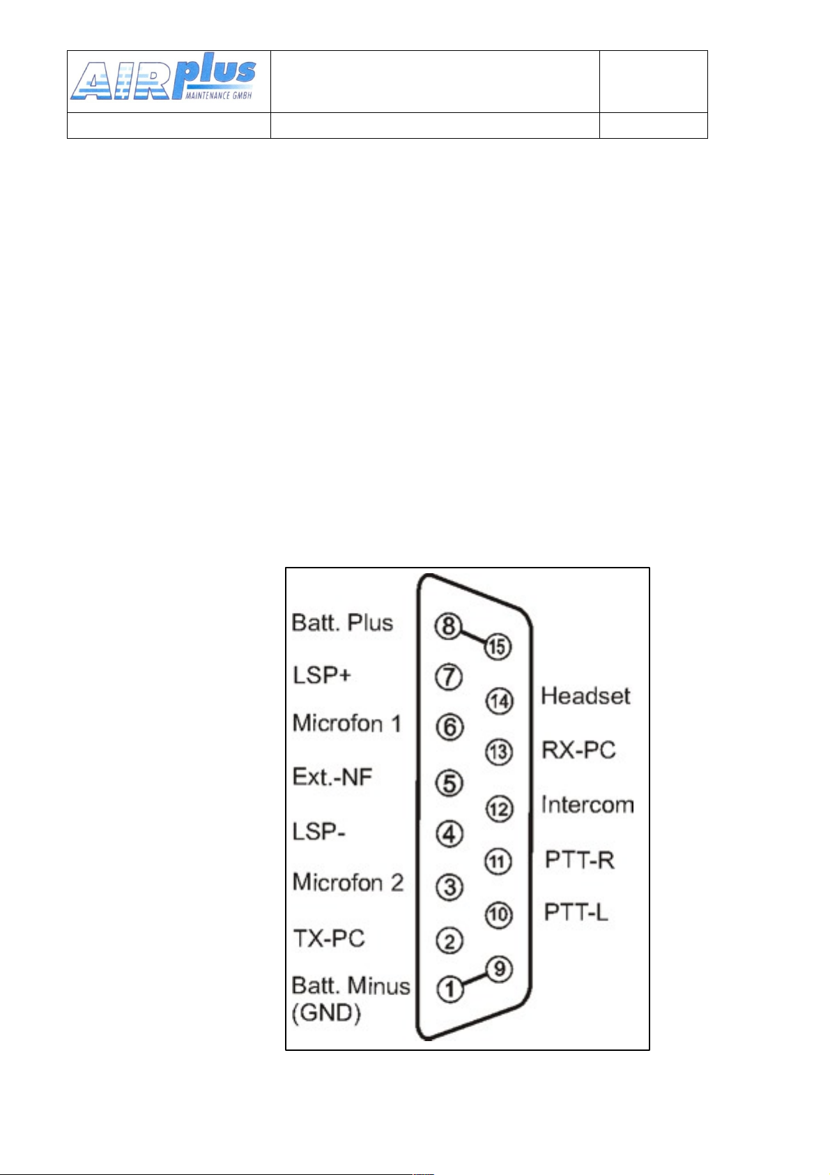
The 15-pin D-Sub connector contains all electrical connections except the
antenna.
The battery plus connection must be protected with a
4amps slow blow fuse !
5.6.1.Microphone-Connection
Both the L (left) and R (right) microphone input channels can either be
connected to standard microphones (standard signal level 1Vpp) or to
dynamic microphones (standard signal level 5mV to 10mV).
For standard microphones a supply voltage of 8V at 330Ω is provided.
Elementary Electret microphones can also be connected. They have
considerably lower signal levels and therefore require an 8V supply
voltage.
The microphone input channel amplifier gain can be selected via the the
MIC-Setup menu 3.4.10.
When dynamic microphones are used in gliders the 8V supply voltage is
switched off for power saving purposes.
Standard microphones normally used in headsets together with dynamic
microphones generally can not be used at the same time.
Motor gliders should have a toggle switch installed to differentiate
between motor less flight with dynamic microphones and powered flight
with headsets.
When the AUTO mode is selected in the MIC-Setup menu the KRT2
automatically recognizes to which microphone type has been switched
and acts accordingly.
33 of 52
Page 34
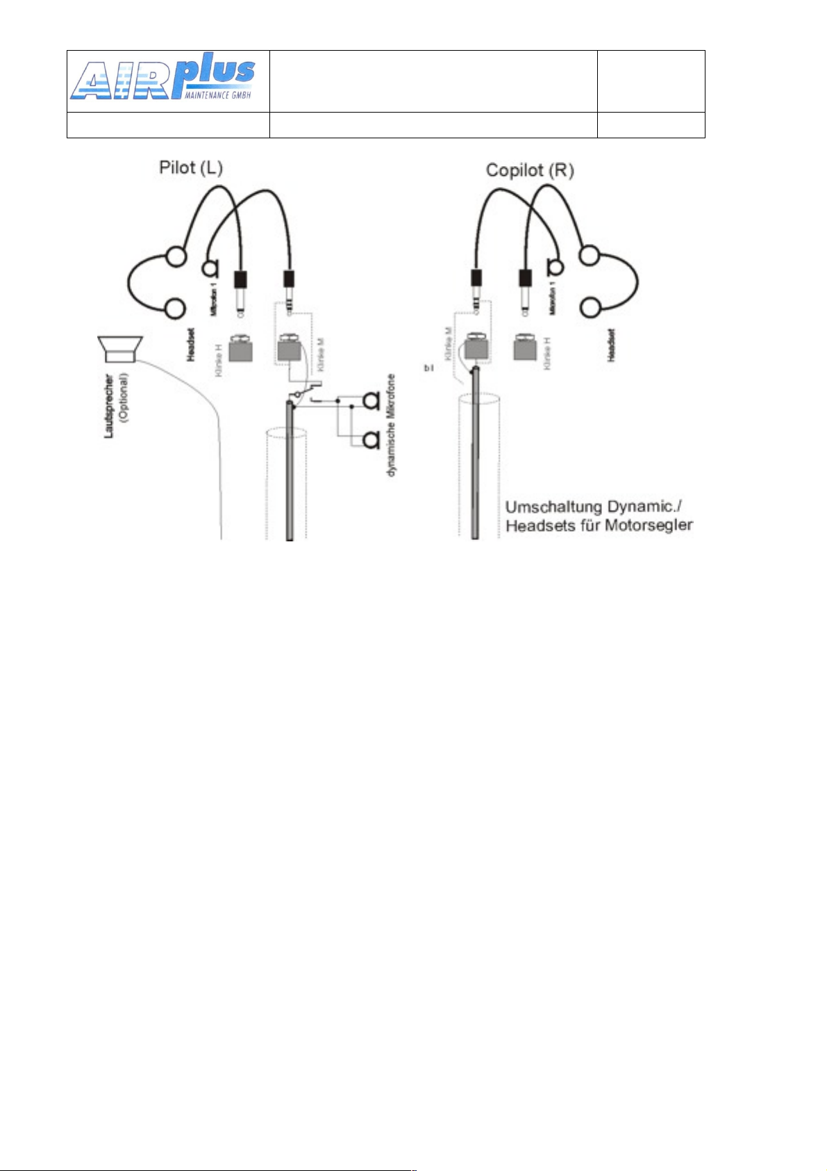
Because the 8V supply voltage is switched off when dynamic microphones
User & Installation manual
VHF- Communication Transceiver
Doc.-Nr:
DE-3000-800100e
KRT2 & KRT 2A
Revision 5.0
Software >5.00
are used during glider flight the second (copilot) headset microphone is
disabled.
A maximum of two microphones of same type may be connected to each
microphone input channel.
5.6.2.Earphone Connection
Several earphones of same type can be connected in parallel. The total
impedance should not be less than 60 Ohms.
5.6.3.External Audio Input
Audio alarms or even music can be made available via the external audio
input. When this input is not used it must be connected to ground in order
to avoid noise. PIN5 must be connected to Battery minus (GND).
34 of 52
Page 35

5.7. Finally Audio-Setup
User & Installation manual
VHF- Communication Transceiver
Doc.-Nr:
DE-3000-800100e
KRT2 & KRT 2A
Revision 5.0
Software >5.00
This is an overview for a correct audio set up depending on the usage.
5.7.1.For gliders
Press button AUD 3x for VOX: Set to VOX 10 (turn off).
Press button AUD 4x for TXm: Set to TXm**.
Press button AUD 6x for EXT: Set to EXT 00 (turn off).
Press button AUD 10x for EXT: Set to MIC-Level 11.
5.7.2.For motor gliders
For change mode (motoring & headset – gliding & dynamic microphone)
Press button AUD 3x for VOX: Set to VOX 3.
on condition at motoring.
Press button AUD 4x for TXm: Set to TXm**.
Press button AUD 6x for EXT: Set to EXT 00 (turn off),
or on condition.
Press button AUD 10x for EXT: Set to MIC-Level 5,
select AUTO
5.7.3.Für Motor planes
Press button AUD 3x for VOX: Set to VOX 3 (turn off).
Press button AUD 4x for TXm: Set to TXm**,
or on condition.
Press button AUD 6x for EXT: Set to EXT 00 (turn off),
or on condition.
Press button AUD 10x for EXT: Set to MIC-Level 3,
or on condition.
35 of 52
Page 36
5.8. Wiring
User & Installation manual
VHF- Communication Transceiver
Doc.-Nr:
DE-3000-800100e
KRT2 & KRT 2A
Revision 5.0
Software >5.00
5.8.1.Wire Gauges
Supply lines (Power, GND): AWG18 (0,96 mm²)
Control lines: AWG22 (0,38 mm²)
All wires must be aviation certified.
5.8.2.Connector Pin-Configuration
36 of 52
Page 37

User & Installation manual
VHF- Communication Transceiver
Doc.-Nr:
DE-3000-800100e
KRT2 & KRT 2A
Revision 5.0
Software >5.00
37 of 52
Page 38
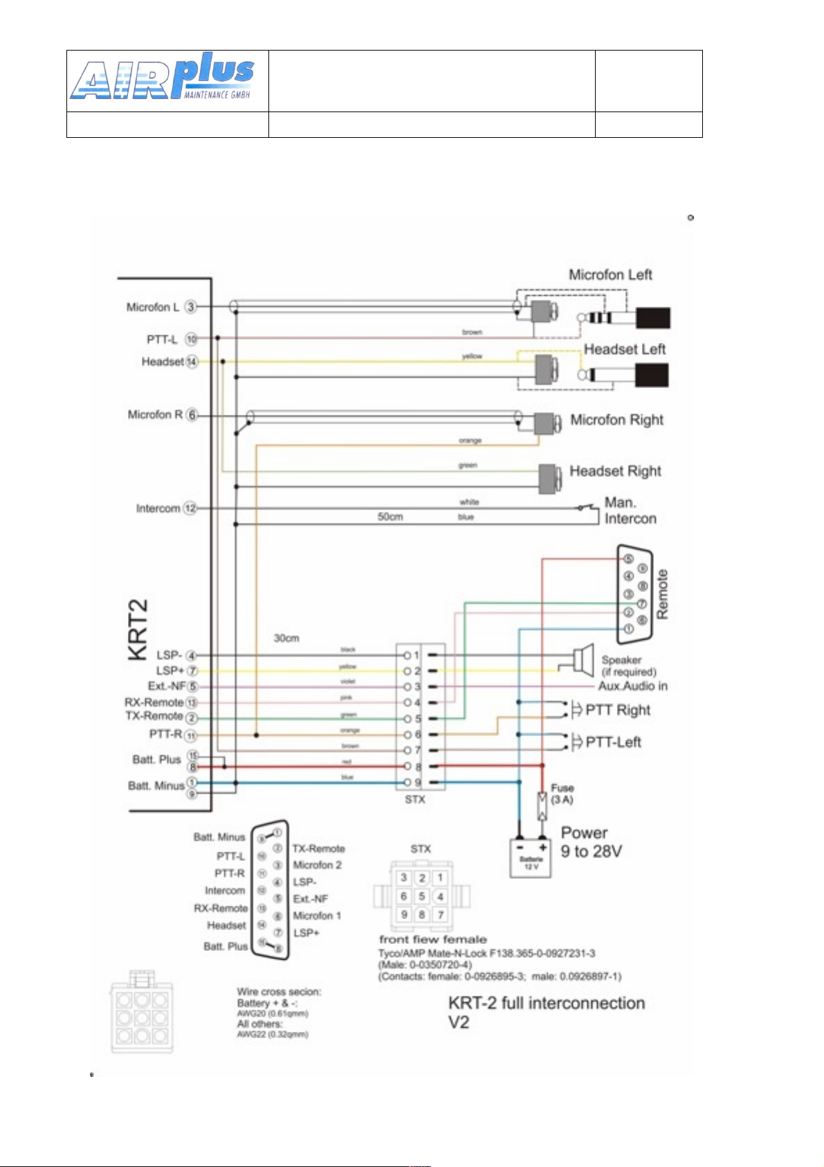
5.8.3.Wiring Diagram
User & Installation manual
VHF- Communication Transceiver
Doc.-Nr:
DE-3000-800100e
KRT2 & KRT 2A
Revision 5.0
Software >5.00
38 of 52
Page 39
User & Installation manual
VHF- Communication Transceiver
Doc.-Nr:
DE-3000-800100e
KRT2 & KRT 2A
Revision 5.0
Software >5.00
39 of 52
Page 40
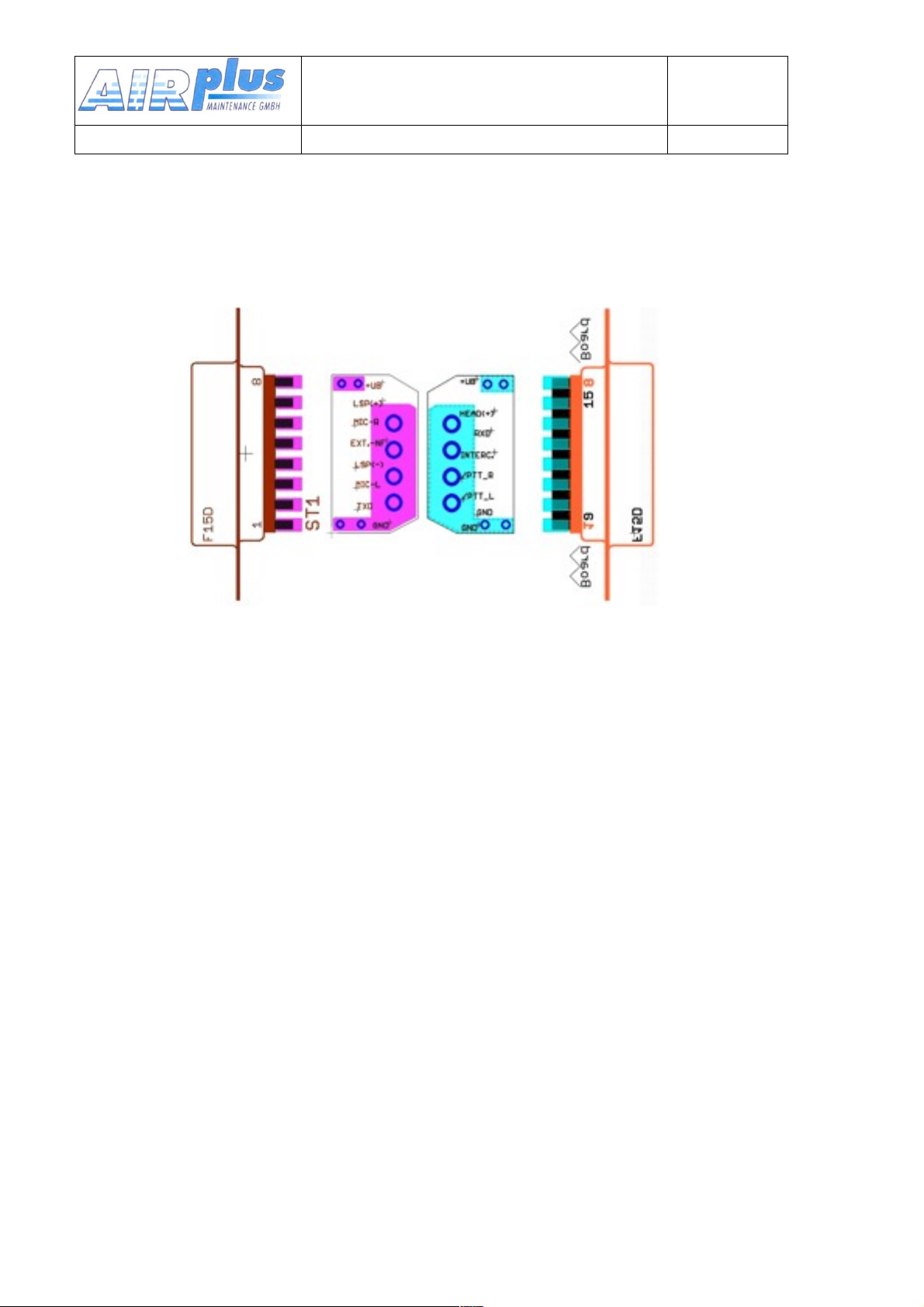
5.8.4.Connection support
User & Installation manual
VHF- Communication Transceiver
Doc.-Nr:
DE-3000-800100e
KRT2 & KRT 2A
Revision 5.0
Software >5.00
In order to connect shields of all cables at a single point and to avoid
ground loops an adapter board as shown is recommended.
The adapter board is placed between the connector pin rows and
soldered to the BAT plus pins 8,15 and GND pins 1,9. Further information
printed on the board serves to connect all cables to its corresponding
pins.
40 of 52
Page 41
5.9. Antenna
User & Installation manual
VHF- Communication Transceiver
Doc.-Nr:
DE-3000-800100e
KRT2 & KRT 2A
Revision 5.0
Software >5.00
5.9.1.Antenna Selection
• A 50 Ohms impedance VHF-COM-antenna is required.
• The antenna must be approved in respect to aircraft type and
installation location.
• The antenna specifications can only be fulfilled when properly installed
5.9.2.Installation Recommendation
• The manufactures instructions have to be observed.
• The metallic contact between airplane surface and antenna ground
must be very good. Non-metallic airplanes must have installed a metal
sheet, foil or mesh of at least 80×80 cm inside the fuselage as electric
counterweight..
• In order to avoid interference the distance between a COM an NAV
antenna or between a COM and another COM antenna should be as
large as possible. A distance of 2 meters normally is sufficient.
• The antenna must vertically be installed as far as possible away from
parts like propeller, landing-gear, rudder etc., that may influence
propagation of the radio signals.
• In gliders the internal antenna provided by the airplane manufacturer is
to be used.
The RF-antenna cable may not be part of other cable
sets like power-supply or microphone. It must not be placed
together with any other COM, NAV or transponder antenna cable.
41 of 52
Page 42
5.10. Microphone general
User & Installation manual
VHF- Communication Transceiver
Doc.-Nr:
DE-3000-800100e
KRT2 & KRT 2A
Revision 5.0
Software >5.00
The correct setting of the MIC and VOX values is of great importance for
Intercom system (see 3.4.3. VOX Intercom Voice Trigger Level and 3.4.10.
MIC Setup).
The VOX intercom voice trigger level must be set to such a value that the
intercom system is activated when speaking at a normal voice level into
the microphone. It shall not be triggered by normal cockpit noise.
When there is extreme cockpit noise or there are uncompensated
microphones VOX can be deactivated with VOX=01 to enable manual
intercom operation.
The manual intercom operation is activated with one or two separate,
parallel connected, optional intercom switches. These switches are not the
PTT switches. The intercom switches connect pin12 (intercom) with GND
(pin1and9).
An “e” will be indicated if pin12 is not on GND.
Communication with the VOX system requires pin 12 to be connected to
GND by means of one or two intercom switches.
The KRT2 unit transmits only when a PTT switch is pressed.
Cockpit noise suppression is only possible with differential microphones
used in modern headsets. Normal Electret microphones are not suitable.
5.11. Post-Installation Check
A certified maintenance shop must verify the proper
operation of the VHF transceiver.
A complete check of all airplane systems is required to certify that the new
wiring is not causing any malfunction.
The standing wave ratio must be less than 3:1.
42 of 52
Page 43
A test flight is recommended to verify proper transceiver operation.
User & Installation manual
VHF- Communication Transceiver
Doc.-Nr:
DE-3000-800100e
KRT2 & KRT 2A
Revision 5.0
Software >5.00
The following items should be checked:
• Check transceiver operation with a radio station at least 50 km away
when at 2000ft or above.
• Check if there is unusual electrical interference or noise.
• If possible check the transceiver operation on low and high
frequencies of the VHF frequency band.
5.12. Starting Up
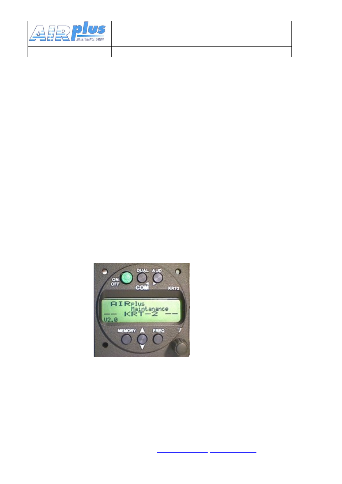
Switch the unit on with the ON button.
The following display will appear:
The start display shows device type and the software number. It then
changes into the normal operating mode (Direct Input).
5.13. Accessories
Suitable accessories like antennas, cable sets, and switches can be
purchased at our online shop on www.AIRplus- avionics.com.
43 of 52
Page 44

User & Installation manual
VHF- Communication Transceiver
Doc.-Nr:
DE-3000-800100e
KRT2 & KRT 2A
Revision 5.0
Software >5.00
44 of 52
Page 45
5.14. Drawings
User & Installation manual
VHF- Communication Transceiver
Doc.-Nr:
DE-3000-800100e
KRT2 & KRT 2A
Revision 5.0
Software >5.00
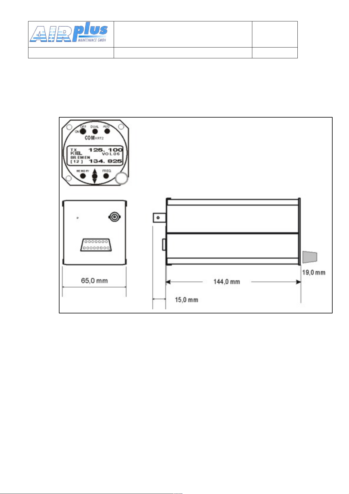
5.14.1.Dimensions
45 of 52
Page 46
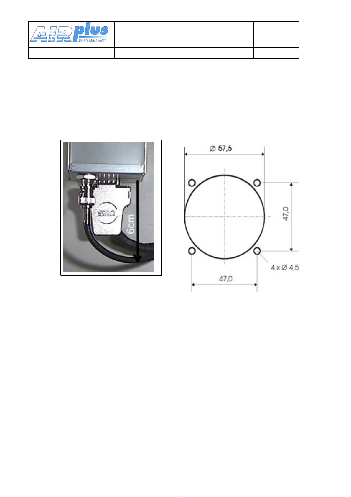
5.14.2.Installation Directions
User & Installation manual
VHF- Communication Transceiver
Doc.-Nr:
DE-3000-800100e
KRT2 & KRT 2A
Revision 5.0
Software >5.00
Connection Area Panel Cut-out
46 of 52
Page 47
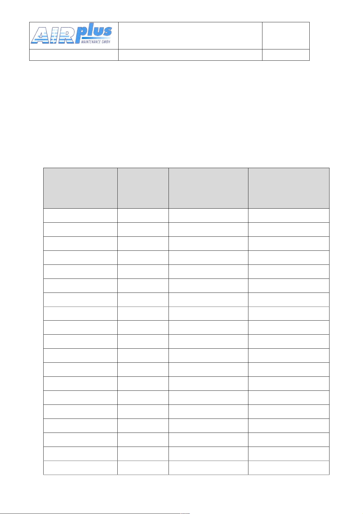
6.ANNEX
Operating
frequency
(MHz)
Cannel
Spacing
(kHz)
Displayed
channel
8.33/25 kHz Mode
Displayed
Channel
25 kHz Mode
118.0000
25
118.000
118.000
118.0000
8.33
118.005
118.0083
8.33
118.010
118.0166
8.33
118.015
118.0250
25
118.025
118.020
118.0250
8.33
118.030
118.0333
8.33
118.035
118.0416
8.33
118.040
118.0500
25
118.050
118.050
118.0500
8.33
118.055
118.0583
8.33
118.060
118.0666
8.33
118.065
118.0750
25
118.075
118.070
118.0750
8.33
118.080
118.0833
8.33
118.085
118.0916
8.33
118.090
118.1000
25
118.100
118.100
118.1000
8.33
118.105
etc.
etc.
etc.
etc.
User & Installation manual
VHF- Communication Transceiver
Doc.-Nr:
DE-3000-800100e
KRT2 & KRT 2A
Revision 5.0
Software >5.00
6.1. Frequency / Channel- schedule
The following table contains the operating and displayed frequencies
between 118.000 and... 118.10 0 MHz. The table can be continued up to
136.975 MHz following the same principle.
47 of 52
Page 48

User & Installation manual
VHF- Communication Transceiver
Doc.-Nr:
DE-3000-800100e
KRT2 & KRT 2A
Revision 5.0
Software >5.00
48 of 52
Page 49
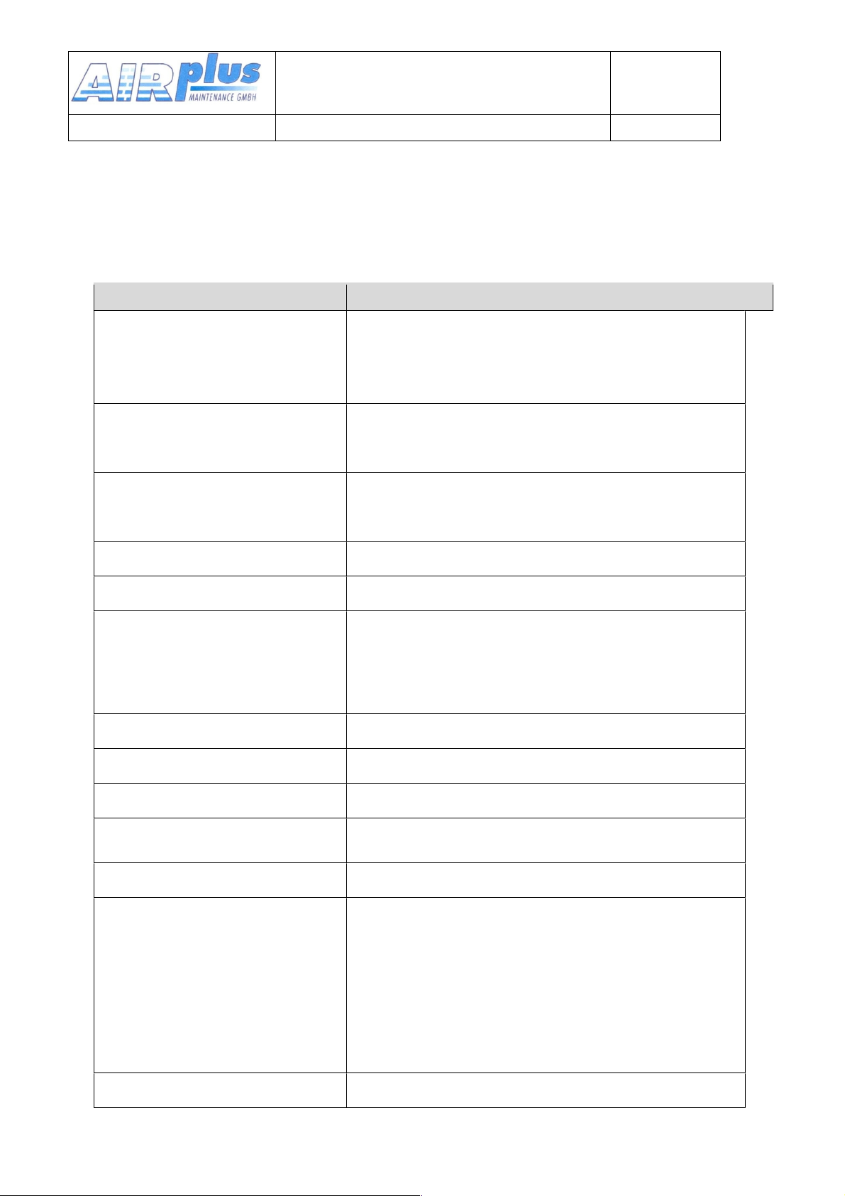
6.2. Technical Data
GENERAL
Compliance
Standards
ETSO-2C169a, ED-23B Class 4
ED-23B Class C
TSO-C169a,Class 6
TSO-C169a, Class H1 & H2
Standards
EUROCAE ED-23B
RTCA DO-160E
RTCA DO-178B Software Level D
Dimensions
Height: 65 mm
Width: 65 mm
Depth: 144mm plus rear panel plugs 60mm
Weight
0.36 kg
Mounting
panel mounting, cut-out Ø 57 mm
Temperature Ranges
Operation
-20 °C to +55 °C
Storage
-55 °C to +85 °C
Maximum Height
35000 ft
Vibration
DO-160E, Cat. S, Vibration Curve M
Humidity
RTCA DO-160E, Cat. A
Shock
6 G operation
20 G crash safety
RTCA DO-160F ENV. CAT.
[C1Z]CAA[SM]XXXXXXZBAAA[YY]M[B3F3]XXA
Power Supply
9 VDC to 33VDC test @ 12VDC
•
Transmitter: 2.0 A (typ.)
•
Receiver: 0.1 A
•
Illumination 0.02A
•
Audio Power amp. Up to 1A
emergency operation: 9 VDC
Power Consumption
Standby 1W, Transmit 30 W
Frequency Range
118.000 .. 136.995 MHz
User & Installation manual
VHF- Communication Transceiver
Doc.-Nr:
DE-3000-800100e
KRT2 & KRT 2A
Revision 5.0
Software >5.00
49 of 52
Page 50
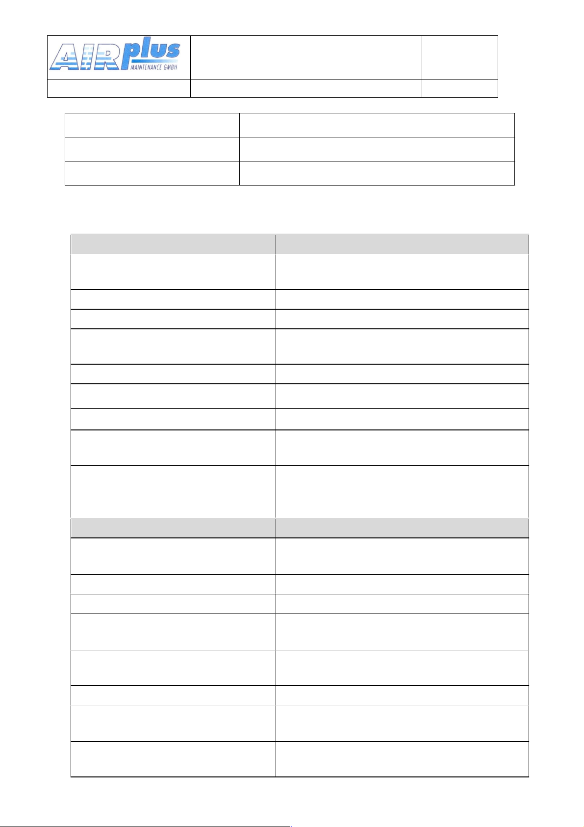
Frequency Stability
±5 ppm
Fuse
external fuse required: 4 A, slow-blow
Compass Safe Distance
30 cm
TRANSMITTER
POWER OUTPUT
6 W (nominal)
4 W (minimal)
HARMONIC DISTORTION
<10 % at 70 % modulation
SIDETONE OUTPUT
>0,5W an 300Ω (head set output)
MICROPHONE INPUTS
2 x standard (50mV…2V) into 100Ω
or 2 x dynamic
HARMONIC CONTENT
>60dBc
MODULATION FIDELITY
deviation <6 dB von 350…2500Hz
CARRIER NOISE LEVEL
>35dB at 70% Modulation index
UNWANTED FREQUENCY
MODULATION
<1kHz at m=70% / 1kHz
DUTY CYCLE
2 minutes on, 4 minutes off;
automatic turn-off after 2 minutes
continuous transmitter operation
RECEIVER
SENSITIVITY
-105 dBm (>6 dB S+N/N,
m = 30 % / 1 kHz)
BANDWIDTH / 25 KHZ
-6-dB-bandwidth > ±8.0 kHz
BANDWIDTH / 8.33 KHZ
-6-dB-bandwidth > ±2.78 kHz
SELECTIVITY
(channel spacing 25 KHZ)
-40-dB-bandwidth < ±17.0 kHz
-60-dB-bandwidth < ±22.0 kHz
SELECTIVITY
(channel spacing 8.33 KHZ)
-60-dB-bandwidth < ±7.37 kHz
SPEAKER OUTPUT
≥4 W into 4 Ω
AGC CHARACTERISTIC
Deviation des NF-output< 6 dB
from 10 µV to 10 mV
SQUELCH
Automatic Squelch (adjustable)
User & Installation manual
VHF- Communication Transceiver
Doc.-Nr:
DE-3000-800100e
KRT2 & KRT 2A
Revision 5.0
Software >5.00
50 of 52
Page 51

SPURIOUS RESPONSES
> 80 dB
DISTORTION (350…2500Hz)
<25% at rated power (85% / -33dBm)
<10% at 10dB below rated power
(70% / -33dBm)
User & Installation manual
VHF- Communication Transceiver
Doc.-Nr:
DE-3000-800100e
KRT2 & KRT 2A
Revision 5.0
Software >5.00
51 of 52
Page 52

User & Installation manual
VHF- Communication Transceiver
Doc.-Nr:
DE-3000-800100e
KRT2 & KRT 2A
Revision 5.0
Software >5.00
52 of 52
 Loading...