

Page 1

ATA J2200-VoIP GATWAY User’s Manual
User’s Manual
for the
ATS J2200
For use with Internet Phone service by SunRocket
To enjoy all the benefits of this product, please review the
information contained in this manual
Page 2

ATA J2200-VoIP GATWAY User’s Manual
Introduction....................................................................................................................................................4
Hardware Overview...................................................................................................................................4
Software Overview ....................................................................................................................................4
IVR Interface for The ATS J2200X ..............................................................................................................5
Quick Guide of ATA Network setup automatically......................................................................................7
ATA Network Setup Automatically Step By Step ........................................................................................8
Ethernet Adapter Detection .......................................................................................................................9
The Detection of the Network Environment ...........................................................................................10
DHCP User Network Environment: ........................................................................................................11
PPPoE User Network Environment:........................................................................................................12
Fix IP User Network Environment:.........................................................................................................13
To Test J2200X Network Settings:..........................................................................................................14
The Network Settings of J2200X was unsuccessful:...............................................................................15
J2200X Reboot ........................................................................................................................................16
The Installation Finished .........................................................................................................................17
Setup the ATS-J2200X by Web Browser....................................................................................................18
System Information .................................................................................................................................18
Single computer environment quick setup ..............................................................................................20
Setting Up the TCP/IP Protocol...............................................................................................................21
General Configuration .............................................................................................................................24
DHCP/Cable Users: .................................................................................................................................24
Fixed IP Users: ........................................................................................................................................24
ADSL Users (PPPoE dial-up connection): ..............................................................................................25
Multiple computers environment quick setup: ........................................................................................27
Phone Book..............................................................................................................................................29
Phone Settings .........................................................................................................................................29
Call Forwarding:......................................................................................................................................29
Volume Settings: .....................................................................................................................................30
Network ...................................................................................................................................................31
SIP Settings..............................................................................................................................................33
System Auth.............................................................................................................................................34
Save Change & Reboot............................................................................................................................35
Update......................................................................................................................................................35
Engineering webpage...................................................................................................................................36
Engineer usage webpage list....................................................................................................................36
Update.htm...............................................................................................................................................36
Natset.htm................................................................................................................................................37
Dmzset.htm..............................................................................................................................................37
Vsset.htm .................................................................................................................................................38
Page 3

ATA J2200-VoIP GATWAY User’s Manual
Toneset.htm .............................................................................................................................................38
Speakerset.htm.........................................................................................................................................38
Vlanset.htm..............................................................................................................................................39
Setup the ATS-J2200X by using Console (Hyper Terminal)......................................................................40
How to make a phone call ...........................................................................................................................49
Get a FWD account .....................................................................................................................................49
Page 4

ATA J2200-VoIP GATWAY User’s Manual
Introduction
This user’s manual is for ATS J2200X. It will explain the IVR instruction, web configuration
and command line configuration for the ATS J2200X. Before using the ATS J2200X, some
setup processes are required to make the ATS J2200X work properly. Please refer to the
Setup Menu for further information.
Hardware Overview
The ATS J2200X has the following interfaces for Networking, telephone interface, LED
indication, and power connector.
1.1.1 Two RJ-45 Networking interface, these two interfaces support 10/100Mps Fast
Ethernet. You can connect one RJ-45 Fast Ethernet port to the ADSL or Switch,
and connect the other one to your computer.
1.1.2 One RJ-11 Type analog telephone jack interfaces. You can connect one analog
telephone to the terminal adapter.
1.1.3 LED Indication: There are three LED indicators in the ATA-1000 to show the
Power, Register, and Off-Hook indication.
Software Overview
Network Protocol
SIP v1 (RFC2543), v2(RFC3261)
IP/TCP/UDP/RTP/RTCP
IP/ICMP/ARP/RARP/SNTP
TFTP Client/DHCP Client/ PPPoE Client
Telnet/HTTP Server
DNS Client
NAT/DHCP Server
Codec
G.711: 64k bit/s (PCM)
G.723.1: 6.3k / 5.3k bit/s
G.726: 16k / 24k / 32k / 40k bit/s (ADPCM)
G.729A: 8k bit/s (CS-ACELP)
G.729B: adds VAD & CNG to G.729
Voice Quality
VAD: Voice activity detection
CNG: Comfortable noise generator
LEC: Line echo canceller
Packet Loss Compensation
Adaptive Jitter Buffer
Call Function
Call Hold
Page 5

ATA J2200-VoIP GATWAY User’s Manual
Call Waiting
Call Forward
Caller ID
3-way conference
DTMF Function
In-Band DTMF
Out-of Band DTMF
SIP Info
SIP Server
Registrar Server (three SIP account)
Outbound Proxy
Tone
Ring Tone
Ring Back Tone
Dial Tone
Busy Tone
Programming Tone
Phone Function
Volume Adjustment
Speed dial key
Phone book
Flash
IP Assignment
Static IP
DHCP
PPPoE
Security
HTTP 1.1 basic/digest authentication for Web setup
MD5 for SIP authentication (RFC2069/ RFC 2617)
QoS
ToS field
NAT Traversal
STUN
Configuration
Web Browser
Console/Telnet
IVR/Keypad
Firmware Upgrade
TFTP
Console
HTTP
IVR Interface for The ATS J2200X
You can use the PSTN phone to configure the ATS J2200X. Please follow the instruction to
configure your terminal adapter.
Page 6

ATA J2200-VoIP GATWAY User’s Manual
Group IVR Action IVR Menu Parameter (s) Notes
Function Reboot #195# None After you hear “Option Successful,”
hang-up. The system will reboot
automatically.
Function Factory Reset #198# None System will automatically Reboot.
WARNING: ALL
“User-Changeable” NONDEFAULT
SETTINGS WILL BE LOST! This
will include network and service
provider data.
Info Check IP Address #120# None IVR will announce the current IP
address of the ATA-1000
Info Check IP Type #121# None IVR will announce if DHCP in
enabled or disabled.
Info Check Phone Number #122# None IVR will announce current in use
VoIP number
Info Check Network Mask #123# None IVR will announce the current
network mask of the ATA-1000.
Info Check Gateway IP
Address
#124# None IVR will announce the current
gateway IP address of the
ATA-1000.
Info Check Primary DNS
Server Setting
#125# None IVR will announce the current
setting in the Primary DNS field.
Info Check Firmware Version #128# None IVR will announce the version of
the firmware running on the
ATA-1000.
Setting Set DHCP client #111# None The system will change to DHCP
Client type.
Setting Set Static IP Address #112xxx*xxx*xxx*xxx# Enter IP address using numbers on
the telephone key pad. Use the *
(star) key when entering a decimal
point.
DHCP will be disabled and system
will change to the Static IP type.
Setting Set Network Mask #113xxx*xxx*xxx*xxx# Enter value using numbers on the
telephone key pad. Use the * (star)
key when entering a decimal point.
Must set Static IP first.
Setting Set Gateway IP Address #114xxx*xxx*xxx*xxx# Enter IP address using numbers on
the telephone key pad. Use the *
(star) key when entering a decimal
point.
Must set Static IP first.
Setting Set Primary DNS Server #115xxx*xxx*xxx*xxx# Enter IP address using numbers on
the telephone key pad. Use the *
(star) key when entering a decimal
point.
Must set Static IP first.
Setting Set Codec #130+[1-8]# 1:G.711 u-Law, 2: G.711 a-Law, 3:
G.723.1, 4: G.729a, 5: G.726 16K,
6: G.726 24K, 7: G.726 32K, 8:
G.726 40K,
You can set the codec you want to
the first priority.
Setting Set Handset Gain #131+[00~15]# Handset Gain from 0~15 You can set the Handset gain to
proper value, default is 6.
Setting Set Handset Volume #132+[00~12]# Handset Volume from 0~12 You can set the Handset volume to
proper value, default is 10.
Page 7

ATA J2200-VoIP GATWAY User’s Manual
Quick Guide of ATA Network setup automatically
You can enjoy the ATA free and relaxed with connect network. You just connect it by following
step, you do talk to anybody with the ATA.
Refer to the Connection Graph above; connect ATS-J2200X with your personal computers and
telephone:
Connect your modem and WAN port of ATS-J2200X with network cable.
Connect your computer and LAN/PC port of ATS-J2200X with network cable
Connect your telephone cable to the phone port of ATS-J2200X.
Connect the power cord to ATS-J2200X power port.
According to the connection with ATS-J2200X will be installed network setting automatically
Page 8

ATA J2200-VoIP GATWAY User’s Manual
until put on the CD-ROM. The installation will lead you set up the Ethernet by step
automatically.
Step1: To make sure the connection between your computer with the ATA Box.
Step2: Put the installed CD-ROM into the computer CD-ROM drive.
Step3: The installation will be implemented automatically.
Step4: Just wait about 3~5 minutes until the ATS-J2200X set up ready. It has to take so much
time while you set up the ATS-J2200X at first time, Please hold on a minute.
Step5: After the ATA finished setting network condition, the ATA will reboot and download the
web configure file by itself automatically. You will see the REG LED ON then you can
pick the phone up and enjoy your calling with the ATA. And the computer will be working
well by installing automatically.
ATA Network Setup Automatically Step By Step
While user put on the CD-ROM and auto run by drive, the information page will show on your
screen step by step.
Page 9

ATA J2200-VoIP GATWAY User’s Manual
Ethernet Adapter Detection
The installation will check out your computer Ethernet adapter first if you have more than one
piece of Ethernet adapters. If you have two Ethernet adapters at least, you have to select the
Ethernet adapter you would like to work with internet. Otherwise you will skip this step of
installation.
Page 10

ATA J2200-VoIP GATWAY User’s Manual
The Detection of the Network Environment
The installation is detecting the network environment with J2200X what network type is.
Please wait…
Page 11

ATA J2200-VoIP GATWAY User’s Manual
DHCP User Network Environment:
The installation will auto detect your network environment after put on the CD-ROM with
connection of ATA. Just wait 5 minutes the ATA will detect the DHCP network or Cable Modem
network by itself and set your computer to DHCP mode automatically. While the ATA reboot
and REG LED ON with the installation had finished. Then you can get to call with ATA and the
computer will get DHCP IP from the ATA LAN/PC port.
Page 12

ATA J2200-VoIP GATWAY User’s Manual
PPPoE User Network Environment:
The installation will auto detect your network environment after put on the CD-ROM with
connection of ATA. Just wait 5 minutes the ATA will detect the PPPoE network by itself and
setup your computer to DHCP mode automatically.
1. By detecting PPPoE settings with connection of the ATA, while the page lead you to dial
the PPPoE from your computer, you have to click the PPPoE dialer on your computer to
connect internet and make sure you do connect the internet successful.
2. The ATA PPPoE detection will auto set according to your PPPoE dialer through your
computer.
3. Just wait for 3~5 minutes the ATA will set itself well. If it failed, please redial PPPoE
function from the computer.
4. Then the ATA had been installed successfully and the computer had been set for DHCP
client to get new IP from the ATA LAN/PC port.
Page 13

ATA J2200-VoIP GATWAY User’s Manual
Fix IP User Network Environment:
The installation will auto detect your network environment after put on the CD-ROM with
connection of ATA. Just wait 5 minutes the ATA will detect the Fix IP network by itself and setup
your computer to DHCP mode automatically.
While the ATA reboot and REG LED ON with the installation had finished. Then you can get to
call with ATA and the computer will get DHCP IP from the ATA LAN/PC port.
Page 14

ATA J2200-VoIP GATWAY User’s Manual
To Test J2200X Network Settings:
After network environment settings, the J2200X is testing the network settings by itself. Just
hold on…
Page 15

ATA J2200-VoIP GATWAY User’s Manual
The Network Settings of J2200X was unsuccessful:
Maybe the system didn’t detect the network environment successful. Please proceed the
detection of network environment (Step Ⅱ) again.
Page 16

ATA J2200-VoIP GATWAY User’s Manual
J2200X Reboot
Please wait for J2200X rebooting…
Page 17

ATA J2200-VoIP GATWAY User’s Manual
The Installation Finished
The system executes the network settings successful. On another hand, the J2200X has
downloaded the web configure file from provider automatically. Please check out the J2200X
REG LED ON and the computer is working well. Then you can enjoy having a call with J200X.
Page 18

ATA J2200-VoIP GATWAY User’s Manual
By foregoing step you still couldn’t set the J2200X network settings, you have to setup
the J2200X network settings by login into J2200X web browser.
Setup the ATS-J2200X by Web Browser
The ATS-J2200X provides a built-in web server. You could use Web browser (Internet Explorer,
Mozilla Firefox etc.) to configure ATS-J2200X.
1. Launch your web browser and enter http://192.168.251.1 (the default IP address of the
ATS-J2200X) in the Location or Address field. Press Enter.
2. The password screen now appears. Input username: user and password: test into the
blank field.
3. Click the [Login] button
4. After a successful login, you will see the ATS-J2200X web based management information
page.
Note: If you make any change of settings in the Web Management interface, please do
remember to click the [Submit] button in that page. A message showed you have to
save and reboot the VoIP to take effect notice you to click [Save change & Reboot] on
the navigation panel and click [Save] in the Save changes page. After the system reboot,
all the settings will work properly.
System Information
This is the web based management information page, you can see the ATS-J2200X
current system information like firmware version, company… etc in this page.
Click a link on the navigation panel to go to the corresponding function.
Page 19

ATA J2200-VoIP GATWAY User’s Manual
Table of Navigation Sub-Manu Description
Phone Book Speed Dial Setting Setup the Speed Dial number Speed Dial
Phone information.
Call Forwarding You can set the forward number of your
phone on this page.
SNTP Settings You can set the SNTP servers on this page.
Volume Settings You can set the volume of your phone on this
page.
Block Settings You can set the block period of your phone
on this page.
Caller ID Settings You can enable/disable the caller ID setting
on this page.
Dial Plan Settings You can the set the dial plan on this page.
Flash Time Settings You can set the flash time on this page.
Call Waiting Settings You can enable/disable the call waiting
setting on this page.
Phone Settings
T.38 (FAX) Settings You can enable/disable the FAX function on
this page.
Network Status This page shows current status of network
interfaces of the system.
WAN Settings You can configure the WAN settings on this
page.
Network
LAN Settings You can configure the LAN settings on this
page.
Service Domain Settings You can set information of service domains
on this page.
Port Settings You can set the port number in this page.
Codec Settings You can set the codec settings on this page.
Codec ID Setting You can set the value of Codec ID on this
page.
DTMF Setting You can set the DTMF setting in this page.
RPort Setting You can enable/disable the RPort setting on
this page.
SIP Settings
Other Settings You can set other settings on this page.
System Authority You can change the login username /
password on this page.
Save Change &
Reboot
You have to save changes and reboot
ATS-J2200X to com into effect.
Update Firmware You can update the newest firmware. Update
Restore Default Settings You can click the restore button to restore the
factory settings.
Page 20
ATA J2200-VoIP GATWAY User’s Manual
Single computer environment quick setup
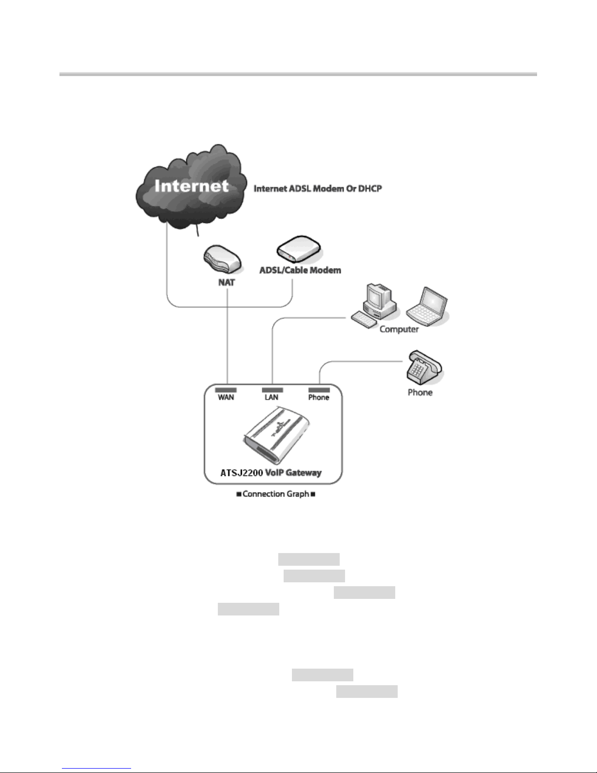
Refer to the Connection Graph above; connect ATS-J2200X with your personal computers and
telephone:
Connect your modem and WAN port of ATS-J2200X with network cable.
Connect your computer and LAN port of ATS-J2200X with network cable
Connect your telephone cable to the phone port of ATS-J2200X.
Connect the power cord to ATS-J2200X power port.
Power LED will be ON. The start-up process will take approximately 20 seconds.
REG LED ON: You may start to use VoIP services and make any phone calls.
REG LED OFF: Internet status error. The ATS-J2200X is not successfully connected with
internet. Please follow the steps below to configure ATS-J2200X.
Page 21

ATA J2200-VoIP GATWAY User’s Manual
Setting Up the TCP/IP Protocol
Configuring Windows 2000 PCs
2 Find the Local Area Connection Status screen by clicking the Start button and then click on
Settings and then Control Panel. From there, double click the Network and Dial-up
Connections Icon, and finally the Local Area Connection item in the window that opens to
see the window below (you may have several local area connection choices-choose the
one that has your Ethernet adapter in the Device Name field):
3 Click the Properties icon to see the window below and then select the item Internet
Protocol (TCP/IP) from the list.
4 Click on the Properties button to see the window below. Select the items Using the
following IP address. Enter IP address: 192.168.251. and Subnet Mask: 255.255.255.0
into the blank field. Click [OK] to finish setting.
Page 22

ATA J2200-VoIP GATWAY User’s Manual
Configuring Windows XP PCs
These instructions assume you are running Windows XP style menu as the default interface. If
you are using the Classic Star menu Interface, please follow the instructions for Windows
2000.
1. Find the Local Area Connection Status screen by clicking the Start button and then click on
Control Panel. From there, click the Network Connection Icon, and finally the Local Area
Connection item in the window that opens to see the window below:
2. Click the properties icon to see the window below and then select the item Internet Protocol
(TCP/IP) from the list.
Page 23

ATA J2200-VoIP GATWAY User’s Manual
3. Click on the Properties button to see the window below. Select the items Using the following
IP address. Enter IP address: 192.168.251. and Subnet Mask: 255.255.255.0 into the
blank field. Click [OK] to finish setting.
Page 24

ATA J2200-VoIP GATWAY User’s Manual
General Configuration
DHCP/Cable Users:
You can pick up telephone and dial #111#, ATS-J2200X will automatically reboot and
obtain an IP address. Now wait for REG LED to light up and you may start using Provider
services.
Otherwise:
1. Click [Network] on the navigation panel.
2. Select sub-menu [WAN Settings].
3. Select [DHCP mode] from IP Type table.
4. Click the [Submit] button to continue.
Fixed IP Users:
1. Click [Network] on the navigation panel.
2. Select sub-menu [WAN Settings].
3. Select [Fixed IP] from IP Type table.
4. Input the below Information “IP address”, “Mask”, “Gateway”, and “DNS server” etc. (You
Page 25

ATA J2200-VoIP GATWAY User’s Manual
may contact you ISP to get these information).
5. Click the [Submit] button to continue.
ADSL Users (PPPoE dial-up connection):
1. Click [Network] on the navigation panel.
2. Select sub-menu [WAN Settings].
3. Select [PPPoE] from IP Type table.
4. Input the below Information ADSL username and password.
5. Click the [Submit] button to continue.
Page 26

ATA J2200-VoIP GATWAY User’s Manual
Page 27
ATA J2200-VoIP GATWAY User’s Manual
Multiple computers environment quick setup:
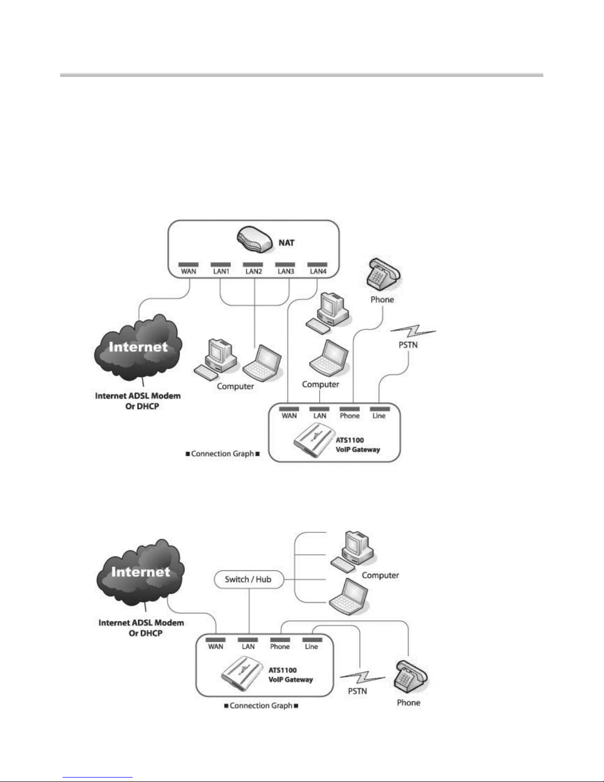
1. NAT (Network Address Translation) owners: Just connect your ATS-J2200X with one of
the LAN port of NAT then pick up your telephone and dial “#111#”. Wait ATS-J2200X to
restart then you may start to make phone calls.
2. If you do not have a NAT: Let ATS-J2200X to start up DHCP / NAT features to provide
other computers are able to browse internet through ATS-J2200X.
Page 28

ATA J2200-VoIP GATWAY User’s Manual
Refer to the graph above; connect ATS-J2200X with Switch/Hub, computer, and telephone:
Connect modem and WAN port of ATS-J2200X with network cable.
Connect Switch/Hub and LAN port of ATS-J2200X with network cable
Connect all computers with Switch/Hub with network cables.
Connect the telephone with the Phone port of ATS-J2200X with phone cable.
Connect power cord to ATS-J2200X power port
Power LED will be ON. The start-up process will take approximately 20 seconds.
Page 29

ATA J2200-VoIP GATWAY User’s Manual
Phone Book
1. Configuration the VoIP Gateway Phone Book. Click [Phone Book] on the navigation panel
and select [Speed Dial Settings].
2. In Speed Dial Settings page, you can add/delete Speed Dial numbers.
Add a phone number: Enter the “Index position number”, “Name”, and “phone
number” (by URL type) of the destination and click [Add Data] button.
Delete a phone number: Select the phone number you want to delete and click
[Delete Selected] button.
Delete all phone numbers: Click [Delete All] button.
3. ATS-J2200X support maximum 10 sets Phone book entries. It is easy to call someone by
dial the index position number (from 0~9) then press “#”.
Phone Settings
In Phone Setting contains Call Forward, SNTP Settings, Volume Settings, Block Setting, Caller
ID, Auto Dial Setting, Flash Time Setting and Call Waiting Setting functions.
Call Forwarding:
You can set the phone number you want to forward in this page. There are three type of
Page 30

ATA J2200-VoIP GATWAY User’s Manual
Forward mode. You can choose All Forward, Busy Forward, and No Answer Forward by
click the icon. When you completed the setting, please click the [Submit] button.
All Forward: Forward it unconditionally. Enter specify name and phone number (by
URL type) in the field.
Busy Forward: While line is engaged or phone set is off-hook, forward to other
number. Enter specify name and phone number (by URL type) in the field.
No Answer Forward: While no one answers the call, forward to the number you
specified. Enter the name and the phone number (by URL type) in the field.
Volume Settings:
You can set the Handset Volume, Ringer Volume, and the Handset Gain. When you
completed the setting, please click the [Submit] button.
Handset Volume: Set the handset volume stands, which can be heard from Gateway
side
Ringer Volume: Set the ring volume stands, which can be heard from Gateway side.
PSTN-Out Volume: Set the PSTN volume stands, which can be heard from Gateway
side.
Handset Gain: Set the gain stands, which the opposite party hears.
PSTN-In Gain: Set the gain stands, which the opposite party hears.
Page 31

ATA J2200-VoIP GATWAY User’s Manual
Network
1. In Network you can check the Network status, configure the Network Settings.
2. Network Status: You can check the current Network setting in this page.
Page 32

ATA J2200-VoIP GATWAY User’s Manual
3. WAN Settings: You can configure the ATS J2200X WAN setting in this page.
The LAN Mode is to set the ATS J2200X Bridge mode or Router mode. If you set the
Bridge Mode, then the two Fast Ethernet ports will be transparent. Otherwise, if you
set the NAT Mode, then the LAN port would router access.
The WAN Setting Configuration item is to set the WAN port’s network environment.
You may refer to your current network environment to configure the ATS J2200X
properly.
The PPPoE Configuration item is to set the PPPoE Username and Password. If you
have the PPPoE account from your Service Provider, please input the Username and
the Password correctly.
When you finished the setting, please click the Submit button.
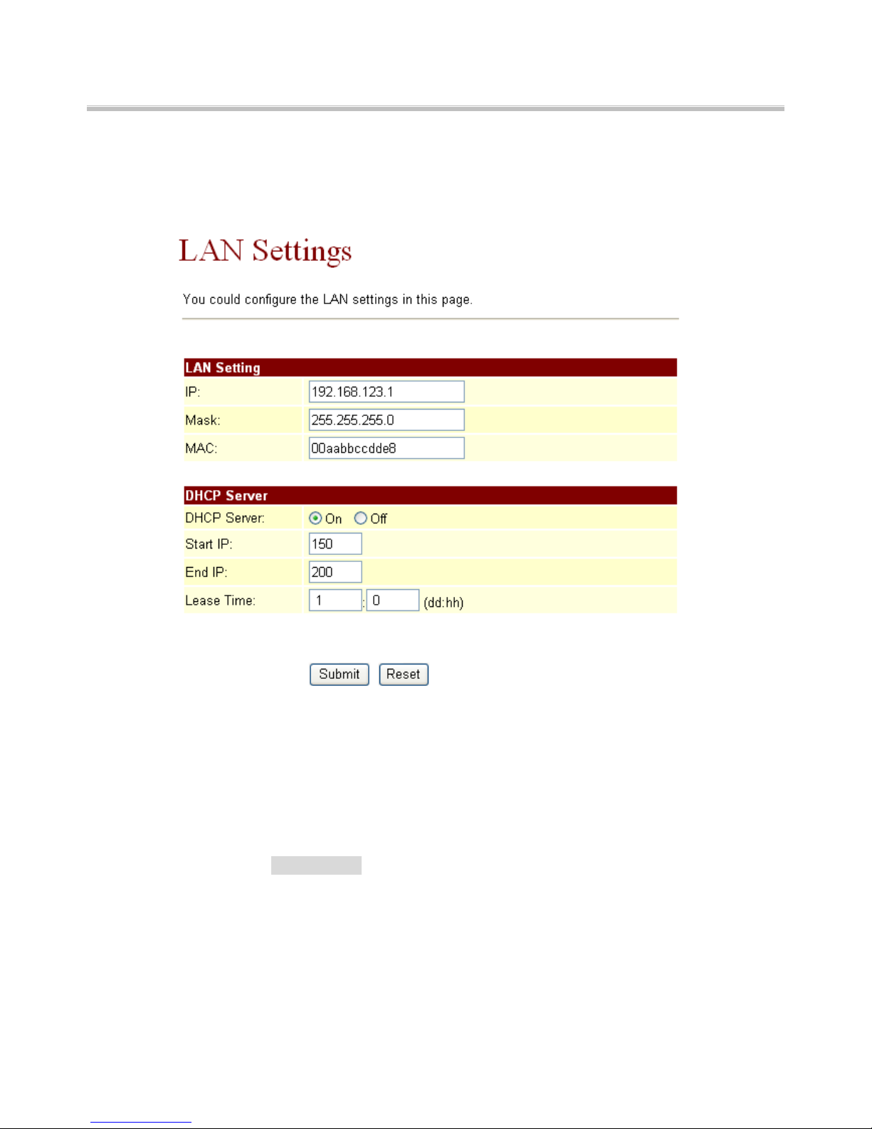
4. LAN Settings: You can configure the ATS J2200XLAN setting in this page.
The LAN Setting item that you could set the router mode address.
The IP was Router mode of LAN port’s Ethernet address. Ex: 192.168.123.1,this means
LAN address would be 192.168.123.xxx Ethernet class.
The Mask was Ethernet Mask that you could set it what you want to set.
The MAC was ATSJ2200X LAN port’s MAC number.
5. DHCP SERVER
The DHCP SERVER is for the other devices to get the IP address from the device. You
can choose to use DHCP server or not.
Page 33
ATA J2200-VoIP GATWAY User’s Manual
You could set start IP and End IP what you want to do for the other devices to get the
IP address from the ATAJ2200’s LAN port.
When you finished the setting, please click the Submit button.
Then don’t forget click the save button.
SIP Settings
1. In Service Domain Function, you need to input the account and the related
information. In this page, please refer to your ISP provider. You can register three SIP
account in the ATS-J2200X. You can dial the VoIP phone to your friends via first
enable SIP account and receive the phone from these three SIP accounts. For the
second phone you can use the same way to register.
2. First you need click Active to enable the Service Domain, then you can input the
following items:
Display Name: you can input the name you want to display.
User Name: you need to input the User Name get from your ISP.
Register Name: you need to input the Register Name get from your ISP.
Register Password: you need to input the Register Password get from your ISP.
Page 34

ATA J2200-VoIP GATWAY User’s Manual
Domain Server: you need to input the Domain Server get from your ISP.
Proxy Server: you need to input the Proxy Server get from your ISP.
Outbound Proxy: you need to input the Outbound Proxy get from your ISP. If your
ISP does not provide the information, then you can skip this item.
Register Period: you need to input the Register Period get from your ISP. This is
count in minute.
3. You can see the Register Status in the Status item. If the item shows “Registered”,
then your ATS-J2200X is registered to the ISP, you can make a phone call directly.
4. When you finished the setting, please click the Submit button.
System Auth.
In System Authority you can change your login name and password.
Page 35

ATA J2200-VoIP GATWAY User’s Manual
Save Change & Reboot
In Save Change you can save the changes you have done. If you want to use new setting
in the ATS-J2200X, you have to click the Save button. After you click the Save button, the
ATS-J2200X will automatically restart and the new setting will effect.
Update
You can update the ATS-J2200X’s firmware to the new one or do factory reset to let the
ATS-J2200X back to default setting.
In New Firmware function you can update new firmware via HTTP in this page. You can
upgrade the firmware by the following steps:
Select the firmware code type, Risc code.
Click the “Browse” button in the right side of the File Location or you can type the
correct path and the filename in File Location blank.
Select the correct file you want to download to the ATS-J2200X then click the Update
button.
In Default Setting you can restore the ATS-J2200X to factory default in this page. You can just
click the Restore button, and then the ATS-J2200X will restore to default and automatically
restart again.
Page 36

ATA J2200-VoIP GATWAY User’s Manual
Engineering webpage
Engineer usage webpage list
You have to login the system first then change the webpage to crystal.htm manually. In
this webpage you will see the list about engineer webpage. You can change the
webpage to what you want.
Update.htm
.1.1 In this page you can update the system’s ROM code, IC Test, Default setting and
Logo.
.1.2 Update ROM code. You can update the ROM code from this function. Please be
noted that if you update the wrong file or during the update process the power is off,
the system will be crashed.
.1.3 Update Logo. The Logo specification is 220x170 jpeg file.
Page 37

ATA J2200-VoIP GATWAY User’s Manual
Natset.htm
.1.4 In this page you can setup the NAT function. The WAN setting is for you to set
how the get the IP address for the device. The LAN setting is for the other devices
to get the IP address from the device. You can choose to use DHCP server or not.
Dmzset.htm
.1.5 In this page you can setup the DMZ function. You need to enable / disable this
function and set the IP address for DMZ.
Page 38

ATA J2200-VoIP GATWAY User’s Manual
Vsset.htm
In this page you can setup the Virtues Server function.
Toneset.htm
In this page you can setup the Tone frequency and cadence to meet the requirement.
Speakerset.htm
In this page you can setup the Speaker function. This function only support in IP Phone
with speaker phone.
Page 39

ATA J2200-VoIP GATWAY User’s Manual
Vlanset.htm
In this page you can setup the VLAN function.
Page 40
ATA J2200-VoIP GATWAY User’s Manual
Setup the ATS-J2200X by using Console (Hyper Terminal)
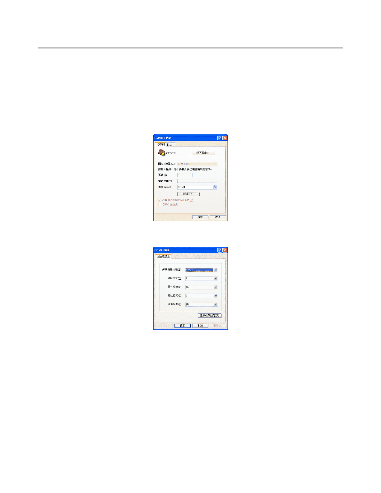
Configure the COM port
First Open the hyper terminal window, select the connection by the COM port, then click
the “Setting” button.
Set the COM port’s setting as following setting. Then click OK.
Login into the ATS-J2200X
After finished the setting, click the “Connect” button (looks like a telephone icon). Then
the hyper terminal is ready to connect to the ATS-J2200X. Press “Enter” and the hyper
terminal will show the “Login: “. Input “root” and press the “Enter” button. Then hyper
terminal will show the “Password: “. Input “test” and press the “Enter” button. Now you
already login the ATS-J2200X. Please follow the CLI command list to configure the
ATA-1000 with proper instruction and value.
Page 41

ATA J2200-VoIP GATWAY User’s Manual
Using CLI command to configure the ATS-J2200X
CLI command list as below:
Itno Command Description
1 ? Show CLI Command
2 arp ARP Configuration
3 ipconfig Interface Configuration
4 save Save to flash
5 reboot Reboot
6 exit Exit
7 debugmode Enter Debug Mode
8 update Update Flash Code/RAM
9 auth
Change User Name and
Password
10 nat NAT Configuration
11 dns DNS Configuration
12 ping ping [-lN] [IP-addr|host-name]
13 sip SIP Configuration
14 ddns DDNS Configuration
15 sntp SNTP Configuration
16 vlan VLAN Configuration
17 time Get System Time
18 mactab Show MAC Learning Table
19 dump Read/Write Memory
20 book Edit phone book
21 reload Reload Factory Setting
22 watchdog WatchDog Function
23 phone Phone Setting
24 weblogo Change Web’s logo
25 dsp Show dsp type
26 addport Add Nat Port Mapping
27 cid Select slic Cid
28 slic read or write slic registers
29 ver Firmware Version
“?” function is to show CLI command list in the screen.
arp function
Itno Command Description
Page 42

ATA J2200-VoIP GATWAY User’s Manual
1 ? Show ‘arp’ Option
2 -a Show ARP Table
3 -d Delete ARP Table
4 -s Set Static ARP Table
5 (null) Show ARP Table
ipconfig function
Itno Command Description
1 ? Show ‘ipconfig’ Option
2 -if0 Interface 0
3 -if1 Interface 1
4 -if2 Interface 2
5 -h Set Host Name
6 -a Set ARP Cache Expire
7 -r Restore Current Setting
8 (null) Show IP Setting
ipconfig –ifN function → N is 0, 1, 2
Itno Command Description
1 ? Show ‘ipconfig -ifN’ Option
2 -t Set Host Type
3 -m Set MAC Address
4 -i Set IP Address
5 -nm Set Net Mask
6 -g Set Gateway
7 -dns0 Set Primary DNS server
8 -dns1 Set Secondary DNS server
9 -dr Set Default Route
10 -nat Set NAT
11 on Enable Interface
12 off Disable Interface
13 -dhcps DHCP Server Setting
14 -ddns Set DDNS
15 -bridge Set Bridge
16 -dev0 Set Device 0 Setting
17 -dev1 Set Device 1 Setting
18 -dev2 Set Device 2 Setting
Page 43

ATA J2200-VoIP GATWAY User’s Manual
19 (null) Show Interface Setting
save function
Itno Command Description
1 ? Show ‘save’ Option
2 -book Save phone book
3 -sys Save system setting
reboot function is to restart the system
exit function is to exit the CLI
debugmode function is to enter the debugmode
update function
Itno Command Description
1 ? Show ‘update’ Option
2 -os Update OSImage (IP filename)
3 -dsp Update DSP Image (IP filename)
4 -all Update All Image (IP filename)
5 -server Update Server (IP filename length)
6 -pcm PCM (IP filename)
-alaw alaw (IP filename)
-ulaw ulaw (IP filename)
-g729 g729 (IP filename)
-g723 g723 (IP filename)
-g726.16 g726.16 (IP filename)
-g726.24 g726.24 (IP filename)
IP is the TFTP server’s IP address, and the filename is the image you
want to download into the system.
auth function
Itno Command Description
1 ? Show ‘auth’ Option
2 -admin
Change Administrator user name /
password
3 -sys0
Change System user0 user name /
password
4 -sys1
Change System user1 user name /
password
5 -sys2
Change System user2 user name /
password
Page 44

ATA J2200-VoIP GATWAY User’s Manual
6 -sys3
Change System user3 user name /
password
7 -sys4
Change System user4 user name /
password
8 -norm0
Change Normal user0 user name /
password
9 -norm1
Change Normal user1 user name /
password
10 -norm2
Change Normal user2 user
name/password
11 -norm3
Change Normal user3 user name /
password
12 -norm4
Change Normal user4 user
name/password
13 -ppp Change PPP user name / password
14 (null) Show auth Setting
In each item includes
Itno Command Description
1 ? Show ‘auth’ Option
2 -user
Change User Name. ’auth -sys3 -user
xxx’
3 -pass
Change Password. ‘auth -sys3 -pass
xxx xxx’
If you want to change the password, you need to type the password twice
in the CLI.
nat function
Itno Command Description
1 ? Show ‘nat’ Option
2 -vs Set ‘nat -vs’ Option
3 -dmz Set ‘nat -dmz’ Option
4 (null) Show NAT Setting
In DMZ item includes
Itno Command Description
1 ? Show ‘nat-dmz’ Option
2 on Enable DMZ
3 off Enable DMZ
Page 45

ATA J2200-VoIP GATWAY User’s Manual
4 -ip Set DMZ IP address
5 (null) Show DMZ Setting
dns function
Itno Command Description
1 ? Show ‘dns’ Option
2 -q DNS query. dns -q domain-name
3 (null) Show DNS Table
ping function
Itno Command Description
1 ? Show ‘ping’ Option
2 -l ping [-l N] [IP-addr|host-name]
3 (null) ping [IP-addr|host-name]
sip function
Itno Command Description
1 ? Show ‘sip’ Option
2 -proxy0 sip -proxy0
3 -proxy1 sip -proxy1
4 -proxy2 sip -proxy2
5 -upnp sip -upnp on/off/show
6 -exts sip -exts sip upnp external-port
7 -extr sip -extr rtp upnp external-port
8 -sipp sip udp port
9 -rtpp sip rtp port
10 -stun sip -stun on/off
11 -rport sip -rport on/off
12 -sserver sip -sserver stun-server
13 -out sip -out outbound-proxy
14 -dump sip –dump
15 -log sip -log on/off
16 -drtp sip -drtp 0/1/2
17 -rtpnc sip -rtpnc on/off
18 -wanip sip –wanip
19 -nattype sip –nattype
20 -hbyrfc sip –hbyrfc
21 -dereg sip -dereg
Page 46

ATA J2200-VoIP GATWAY User’s Manual
22 -restart sip -restart
23 -jbt sip -jitter buffer Threshold
24 (null) Show SIP Setting
ddns function
Itno Command Description
1 ? Show ‘ddns’ Option
2 -type Set DDNS Type
3 -host Set Host Name
4 -wild Set Wild Card Mode
5 -mx Set Mail Exchanger
6 -backmx Set Mail Exchanger Mode
7 -offline Set Offline Mode
8 -user Set Login User Name
9 -pass Set Login Password
10 (null) Show DDNS Setting
sntp function
Itno Command Description
1 ? Show ‘sntp’ Option
2 -on Enable SNTP Client
3 -off Disable SNTP Client
4 -ip1 Set SNTP Server1 IP
5 -ip2 Set SNTP Server2 IP
6 -mode Set SNTP Client Mode
7 -zone
Set GMT Time Zone:
[+|-][hour]:[min]
8 -adjust Set Adjustment Time: [second]
9 (null) Show SNTP Setting
vlan function
Itno Command Description
1 ? Show ‘vlan’ Option
2 -tx Tx Vlan setting
3 -rx Rx Vlan setting
4 (null) Show Vlan Setting
time function
Page 47

ATA J2200-VoIP GATWAY User’s Manual
Itno Command Description
1 ? Show ‘Time’ Option
2 -t Modify Time: hour:min:sec
3 -d Modify date: year:mon:date
4 (null) Show Data & Time
mactab function is to show MAC learning table.
dump function
Itno Command Description
1 ? Show ‘dump’ Option
2 -r dump -r XXXXxxxx
3 -w dump -w XXXXxxxx XX
book function
Itno Command Description
1 ? Show ‘book’ Option
2 -a Show answer list
3 -c Show call list
4 -s speed dial
5 -p phone book
reload function is to Reload Factory Setting, please make sure you want to do
the factory reset.
watchdog function
Itno Command Description
1 ? Show ‘WatchDog’ Option
2 on Enable WatchDog
3 off Disable WatchDog
4 (null) Show WatchDog Setting
phone function
Itno Command Description
1 ? Show ‘phone’ Option
2 -autoanswer phone auto answer
3 -vol Volume setting
4 -block Block Incoming call
5 -ring Set Melody Ringer
6 -forward Auto-forward Incall to Phone[0-9]
Page 48

ATA J2200-VoIP GATWAY User’s Manual
in Book
7 (null) Show Phone Setting
weblogo function
Itno Command Description
1 ? Show ‘weblogo’ Option
2 -on Vender Logo
3 -off Crystal media Logo
4 (null) Show weblogo Setting
dsp function is to show dsp code type.
addport function is to add Nat Port Mapping
cid function
Itno Command Description
1 ? Show ‘cid’ Option
2 -off Disable Slic Cid signal
3 -1 Tx FSK after 1st Ring
4 -2 Tx FSK before 1st Ring
5 -3 Tx DTMF before 1st Ring
6 -4
Tx FSK with Line reversal before
1st Ring
7 -5
Tx DTMF with Line reversal
before 1st Ring
8 -time FSK cid with time message
9 -single Single type FSK CID
10 (null) Show Cid Option
slic function
Itno Command Description
1 ? Show ‘slic’ Option
2 -ring Issue Ring signal
3 -r read slic addr
4 -w write slic addr
5 -a read all slic reg
6 (null) Show slic register
ver function is to show Firmware Version
Page 49

ATA J2200-VoIP GATWAY User’s Manual
How to make a phone call
When your ATS-J2200X is configured properly, you can make a phone call to your friend in
the same Service provider.
If you want to make a phone call, you can dial the phone number and press “#” button to
start to dial the phone number.
The ATS-J2200X also provides some functions that list as below:
1. Call Waiting: When a new call is coming while you are talking, you can push the Flash
button to switch to the new call. You can push the Flash button to switch between the
two calls.
2. Call Hold: You can push the Hold key to hold the current call for a while, then push Hold
key again to keep talking.
3. 3-way conference: If you want to make a 3-way conference call, you can make a phone call to
the first phone number. After the call is established, push the Flash button then you can hear the
Dial tone, then make a phone call to the second phone number. When the second call is
established, press the Flash button again.
Get a FWD account
1. The website is http://www.freeworlddialup.com; you can apply an account to use the
VoIP communication. You can follow the instruction to input the information. After you
finished, you will receive a mail sent by the FWD mail system, you will get the account
information in the mail.
2. When you got the account, you can setup the related information into the ATS-J2200X.
3. You can setup the related information into the ATS-J2200X by web browser. Also you
can use Telnet, Console via CLI command to configure the ATS-J2200X. You need to
input the Proxy Name, Domain Name, Register Name, and password. The Display
Name you can input what you want to let others see.
4. After you registered to the SIP Server, you can try to call your friends who also
registered in the same SIP Server. You just need to dial your friend’s user name
(registered name) and press “#” then you can make a phone call to your friend.
If you want to make a phone call to the other in the internet, first you need to registered in a
Proxy Server (with SIP Server IP, Domain IP, registered name, Password), make sure you
already enable Stun function, then you can try.
Page 50

ATA J2200-VoIP GATWAY User’s Manual
FEDERAL COMMUNICATIONS COMMISSION INTERFERENCE STATEMENT
This equipment has been tested and found to comply with the limits for a Class B digital
device, pursuant to Part 15 of the FCC Rules. These limits are designed to provide
reasonable protection against harmful interference in a residential installation. This
equipment generates, uses and can radiate radio frequency energy and, if not installed and
used in accordance with the instructions, may cause harmful interference to radio
communications. However, there is no guarantee that interference will not occur in a
particular installation. If this equipment does cause harmful interference to radio or television
reception, which can be determined by turning the equipment off and on, the user is
encouraged to try to correct the interference by one or more of the following measures:
– Reorient or relocate the receiving antenna.
– Increase the separation between the equipment and receiver.
– Connect the equipment into an outlet on a circuit different from that to which the receiver
is connected.
– Consult the dealer or an experienced radio/TV technician for help.
CAUTION:
Any changes or modifications not expressly approved by the party responsible for
compliance could void the user's authority to operate the equipment.
 Loading...