

Page 1

CyberChiller Series Installation, Operation & Maintenance Manual
(©October, 2006)
Page 2
CyberChiller Series Installation, Operation & Maintenance Manual
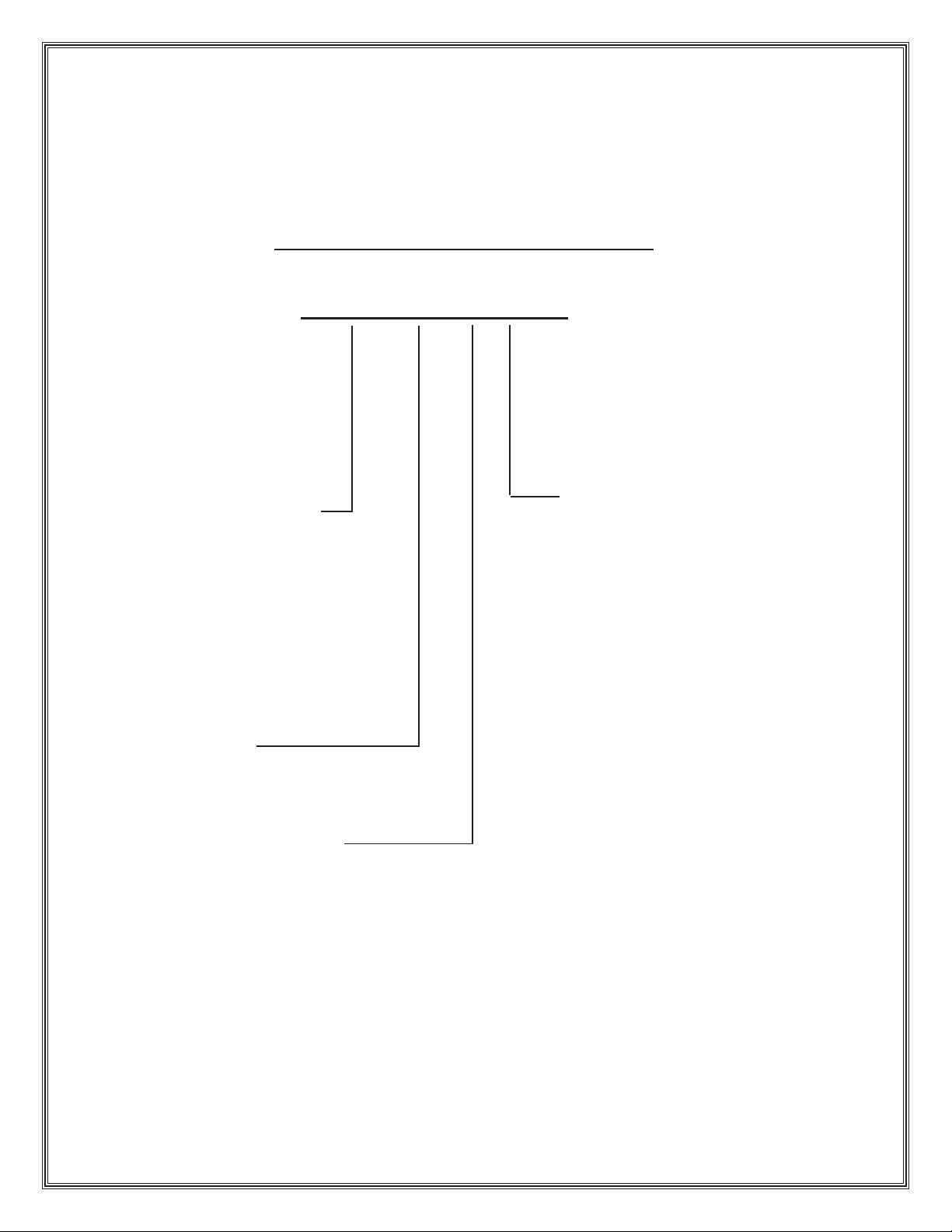
MODEL NOMENCLATURE
CCH-330-D-AR
OHS = Overhead System
CC H = CyberChiller System
VFS = Vertical Floor System
FCS = Floor Console System
GPS = Glycol Pump System
CO S = CyberONE System
MCS = Modular Cyber System
Nominal Capacity in
1,000’s of BTU/Hr
D ( ) = Dual (Two) Circuit System
AR = Air-Cooled Remote (Split)
W/G = Water/Glycol Cooled
(©October, 2006)
Page 3
CyberChiller Series Installation, Operation & Maintenance Manual
TABLE OF CONTENTS
1.0 Introduction.......................................1-1
1.1 General...................................................... 1-1
1.2 Product Description ................................... 1-1
1.2.1 Capabilities and Features .......................... 1-1
1.2.2 Application Ranges.................................... 1-1
1.2.3 General Design .......................................... 1-2
1.2.4 Safety Features......................................... 1-3
1.3 Product Warranty ...................................... 1-4
1.4 Safety........................................................ 1-6
1.4.1 General...................................................... 1-6
1.4.2 Safety Summary........................................ 1-6
2.0 Installation .........................................2-1
2.1 Receiving the Equipment. .......................... 2-1
2.2 Site Preparation......................................... 2-1
2.3 Rigging ...................................................... 2-1
2.4 Mounting/Placement .................................. 2-1
2.4.1 Indoor Equipment....................................... 2-2
2.4.2 Outdoor Equipment.................................... 2-2
2.4.3 Pump Package Installation (Water - Glycol
Systems.................................................... 2-2
2.4.4 Optional Equipment (Field Installed) .......... 2-2
2.4.4.1 Remote Display ......................................... 2-2
2.4.4.2 Remote Water Detector ............................. 2-2
2.5 Piping Connections.................................... 2-3
2.5.1 Process Supply Fluid Lines ....................... 2-3
2.5.2 Refrigerant ................................................. 2-3
2.5.2.1 Split Air Cooled Systems ........................... 2-3
2.5.2.2 Water/Glycol Fluid Cooled Systems .......... 2-4
2.5.3 Pump Package.......................................... 2-5
2.6 Utility Connections .................................... 2-5
2.6.1 Main Power ............................................... 2-5
2.6.2 Controls..................................................... 2-7
2.6.3 Optional Equipment ................................... 2-7
2.6.3.1 Remote Water Detector ............................. 2-7
2.6.4 Interconnecting Field Wiring....................... 2-7
2.6.4.1 Air-Cooled Split Systems
Remote Condenser .................................... 2-8
2.6.4.2 Glycol Systems with Outdoor Fluid Pump
Package .................................................... 2-8
2.7 System Settings and Adjustments............. 2- 9
2.7.1 Chilled Water Supply Charging
Procedures (Evaporator Side) .................... 2-9
2.7.2 Outdoor Heat Exchanger Glycol Charging
Procedures .............................................. 2-10
2.7.3 R-22 Refrigerant Charging Procedures ......2-11
2.7.4 R-407C Refrigerant Charging Procedures ..2-1 1
2.7.5 Low/High Pressure Limit Switch .............. 2-12
2.7.6 Head Pressure Controls........................... 2-13
2.7.6.1 Air-Cooled Systems................................. 2-13
2.7.6.2 Water/Glycol Cooled Systems................. 2-13
2.7.7 Thermal Expansion V alve......................... 2-13
2.7.8 Hot Gas Bypass ...................................... 2-13
2.8 Refrigerant Characteristics....................... 2-14
2.8.1 Pressure/T emperature Settings................ 2-14
2.8.2 Saturated Refrigerant Pressure T ables ..... 2-14
3.0 Start-Up/Commissioning ..................3-1
3.1 Operation ................................................... 3-1
3.2 Step by S tep S tart-Up Instructions ............. 3- 1
3.2.1 Operational Description.............................. 3-1
3.3 Microprocessor Controller
Programming ............................................. 3-2
4.0 Maintenance/Repairs.......................4-1
4.1 Peri odic Gen eral Mai ntenan ce ................... 4-1
4.1.1 General...................................................... 4-1
4.1.2 Compressor ............................................... 4-1
4.1.3 Outdoor Condenser/Fluid Cooler ................ 4-1
4.2 Troubleshooting ......................................... 4-2
4.3 Fie ld Ser vice.............................................. 4-5
4.3.1 Leak Detection .......................................... 4-5
4.3.2 Leak Repair ............................................... 4-5
4.3.3 Refrigerant Piping ...................................... 4-5
4.3.4 General Common Repairs/
Component Replacement........................... 4-5
4.3.4.1 Compressor Failure ................................... 4-5
5.0 Product Support Group ...................5-1
5.1 T echnical Support ...................................... 5-1
5.2 Obtaining Warranty Parts .......................... 5-1
5.3 Obtaining Spare/Replacement Part s .......... 5-1
(©October, 2006)
i
Page 4
CyberChiller Series Installation, Operation & Maintenance Manual
List of Figures
Figure 1- Typical Layout ........................................ 1-2
Figure 2- Typical Installation.................................. 2-1
Figure 3- Typical Piping Air Cooled Systems ......... 2- 3
Figure 4- Typical Piping W ater/Glycol Cooled
Systems ................................................ 2-5
Figure 5- Sample Nameplate ................................. 2-6
Figure 6- Electric Box ........................................... 2-7
Figure 7- Interconnecting Field Wiring
Remote Condenser................................. 2-8
Figure 8- Interconnecting Field Wiring
Glycol Systems ...................................... 2-9
Appendix A - Forms
Checklist for Completed Installation .........................A-1
Periodic General Maintenance
Checks and Service Checklist..................................A-2
Appendix B - Glossary
Definition of T erms and Acronyms ............................B-1
ii
(©October, 2006)
Page 5
CyberChiller Series Installation, Operation & Maintenance Manual
1.0 INTRODUCTION
1.1 General
Congratulations, the CyberChiller™ floor mounted
liquid chiller system covered by this manual is designed and manufactured by Stulz Air Technology
Systems, Inc. (SATS) using the latest, state-of-the-art
control technology . Recognized as a world leader,
SATS provides precision cooling systems with the
highest quality craftsmanship using the finest materials available in the industry . The unit will provide years
of trouble free service if installed and maintained in
accordance with this manual. Damage to the unit from
improper installation, operation or maintenance is not
covered by the warranty .
This manual contains information for installation,
operation, maintenance, troubleshooting and repair .
STUDY the instructions contained in this manual.
They must be followed to avoid difficulties. Sp are part s
are available from Stulz Air T echnology Systems to
insure continuous operation. Using substitute parts or
bypassing electrical or refrigeration components in
order to continue operation is not recommended and
will VOID THE WARRANTY. Due to technological
advancements, components are subject to change
without notice.
CyberChiller systems are designed to precisely control
leaving fluid temperature for fluid cooled equipment
such as server racks, MRI’s, precision cooling units or
other devices. Any use beyond this is deemed to be
not intended. SA TS is not liable for any damage
resulting from improper use. All CyberChiller systems
are designed to be installed indoors unless otherwise
noted on the equipment. Propeller-type condensers
and fluid coolers are designed for outdoor use.
1.2 Product Description
CyberChiller systems are designed to meet the needs
and technical requirements of individual customers.
Each individual module or unit can be supplied with
remote air-cooled condensers (AR) or optional water/
glycol (W/G) cooled heat rejection configurations. The
cooling capacity, in BTU/Hr, will depend on the unit
size, which can range from 120,000 to 330,000 BTU/
Hr. CyberChiller systems are designed to operate with
either R22 or R407C refrigerant. Refer to the unit
nameplate to identify which refrigerant is used with
your unit.
NOTE
The CyberChiller systems are strictly for nonresidential applications.
Refer to the installation drawing supplied with your unit
for layout and dimensions of the cabinet. The
CyberChiller unit is provided with a factory mounted
service disconnect switch with a lockable handle. The
service disconnect switch isolates the unit during
routine maintenance. The system incorporates state of
the art component protection with the use of motor
start protectors and circuit breakers.
An operating manual for the system controller is
provided under separate cover . Refer to that manual for
detailed instructions on operating the system controller provided with your unit.
The standard controller for the CyberChiller unit is the
C6000 microprocessor, which provides the following
features: input/output monitoring status, full integrated
control of cooling, multi-unit control and remote
communication with building management systems.
The controller is typically factory mounted on the front
hinged access door of the unit. As an option the
controller display may be factory supplied for remote
mounting to a wall or control panel.
1.2.1 Capabilities and Features
Dual Refrigeration Circuits
Constant Running Compressor
Vibration Isolation of Compressor
Electronic Hot Gas Bypass
(With control based on the chilled water supply
temperature.)
Heavy Gauge Cabinet Construction
High Density Sound & Thermal Insulation
1.2.2 Application Ranges
The SA TS CCH Modular Line Chiller Units are designed for operation within the following ranges:
Room Temperature Range: 35ºF to 95ºF, non-condensing
environment.
Cold Water Conditions: Between 45ºF and 65ºF.
Voltage Tolerances: 460VAC +/-10%; 208VAC +/-10%.
Frequency: 60 Hz. (as noted on unit nameplate).
Max. Piping Length; Chiller to Air Cooled Condenser:
200 ft equivalent length.
Max. Level Drop; Chiller to Condenser: 20 ft (when
condenser is below the chiller).
Storage Conditions: 35ºF to 95ºF.
NOTE
Damage or malfunctions to the unit due to
storage or operation outside of these ranges
will VOID THE WARRANTY.
(©October, 2006)
1-1
Page 6
CyberChiller Series Installation, Operation & Maintenance Manual
1.2.3 General Design
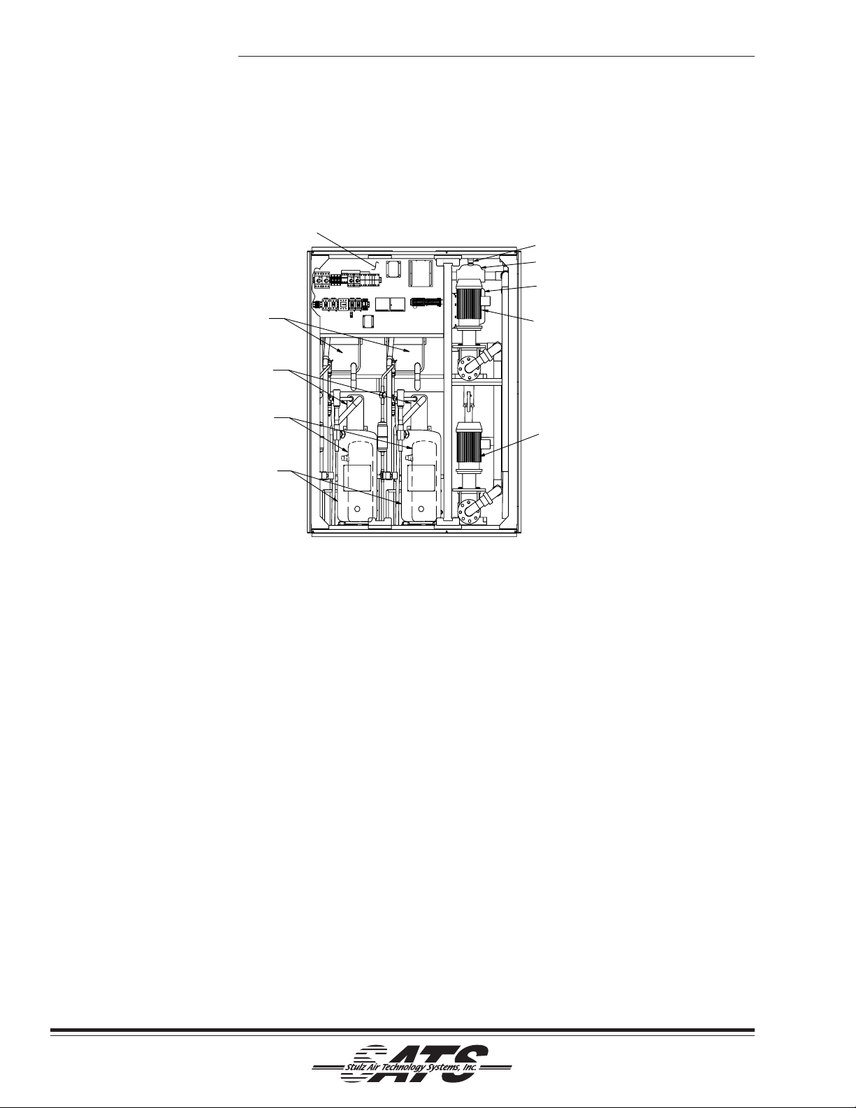
The CyberChiller is divided into 3 areas; a pump section, a refrigeration section and an electrical section. The
housing is a frame type construction. Figure 1 depicts the internal layout of the unit and the location of the major
components.
ELECTRIC BOX
HEAT EXCHANGERS
(EVAPORATORS)
HEAT EXCHANGERS
(CONDENSERS- NOTE 1)
RECEIVERS
(BEHIND COMPRESSORS)
SCROLL COMPRESSORS
NOTE 1: PROVIDED WITH
WATER/GLYCOL COOLED UNITS.
Figure 1- Typical Layout
1.2.3.1 Electric Box Access
The electrical components are protected behind dual
hinged access doors located on the left side of the
unit. The access doors are safety interlocked with the
service disconnect switch preventing the doors from
opening when the switch in the “On” position. The
switch must be turned “Off” to gain access to the
electrical components.
1.2.3.2 Circuit Breakers/ Motor Start Protectors
Individual overload protection is provided by circuit
breaker(s) and motor start protectors. These switches
must be manually re-set once the overload condition is
cleared.
1.2.3.3 Pumps
Multi-stage centrifugal pumps are located in the right
side of the unit to circulate the coolant through the
system. A hinged access door is located on the right
side of the unit. This door may be opened to gain
access to the pump section.
AIR VENT
AIR SEPARATOR
EXPANSION TANK
(BEHIND PUMP #2)
PUMP #2
(OPTIONAL)
PUMP #1
1.2.3.4 Expansion T ank
An expansion tank has been provided on the chilled
water side of the unit to compensate for thermal
expansion of the coolant. An air vent is mounted on
top of the fluid separator .
1.2.3.5 Heat Exchangers
Constructed of 316 stainless steel with brazed plate fin
construction, the evaporator heat exchangers are for
the exchange of heat from the process water/glycol
coolant to the refrigerant.
1.2.3.6 Receivers
Receivers are provided for each refrigeration circuit for
storage of excess refrigerant in the refrigeration cycle.
1.2.3.7 Compressors
The compressors used in this unit are scroll compressors mounted inside the unit on vibration absorbers to
eliminate noise and vibration during operation. The
scroll compressor is designed around two identical
spirals or scrolls that, when inserted together, form
crescent shaped pockets. During a compression
1-2
(©October, 2006)
Page 7

CyberChiller Series Installation, Operation & Maintenance Manual
cycle, one scroll remains stationary while the other
scroll orbits around the first. As this motion occurs,
gas is drawn into the scrolls and moved in increasingly
smaller pockets toward the center . At this point, the
gas, now compressed to a high pressure, is discharged from a port in the center if the fixed scroll.
During each orbit, several pockets of gas are compressed simultaneously , creating smooth, nearly
continuous compression.
Due to the design of the scroll compressor, the internal
compression components always start unloaded even
if the system pressures are not balanced. In addition,
since internal compressor pressures are always
balanced at start-up, low voltage starting characteristics are excellent for scroll compressors
With fewer moving parts, the
scroll compressor sets the
industry standard for reliability among one and a half to
twelve horsepower compressors. The compressor’s
simple design and proven
day-to-day performance
means less maintenance
calls for field personnel.
The scroll compressor has
demonstrated superior
durability . Its axial and radial
compliance make the scroll
compressor more tolerant to liquid refrigerant and
debris - two of the most common causes of system
failure.
The scroll compressor is quiet, but not silent. On
average, the compressor is up to five decibels quieter
than standard piston compressors. A scroll compressor, however , has different sound characteristics from
reciprocating compressors. These sounds do not
affect system reliability or performance.
Upon shut-down of a normal run cycle, the compressor
will run backwards for one or two seconds as the
scrolls internal pressures are equalized. A short
reverse rotation “burp” will result. This sound is normal.
A check valve in the discharge tube of the compressor
prevents the compressor from running backwards for
more than a second or two. This normal direction
reversal of the scrolls at shut down has no effect on
compressor reliability .
Each scroll compressor comes equipped with a
crankcase heater, used to evaporate any liquid that
may have migrated to the compressor during extended
periods on non-operation (>12 hours). The crankcase
heaters are equipped with over current protection.
CAUTION
Prior to initial start-up (only when main power
has been disconnected for 12 hours or longer),
allow at least ten (10) minutes (two (2) hours is
recommended) with main power reconnected.
This will allow sufficient time for the crankcase
heaters to evaporate any liquid that may have
migrated to the compressor crankcase. When
this procedure is completed, the CyberChiller is
ready to be run.
Automatic, staged starting of the compressors is
provided to prevent an in rush of current to the
CyberChiller. High and low pressure safety switches
prevent operation of the compressor during high or low
pressure conditions.
1.2.3.8 Strainer
A “Y” strainer is included to remove any debris that
may be circulated to the chiller.
1.2.4 Safety Features
Low and high-pressure switches are provided for each
refrigeration circuit. The pressure switches are nonadjustable encapsulated control switches. If a high
pressure switch is tripped for any reason, it must be
manually reset. The cause for tripping of the high
pressure switch must be determined. The low pressure
switches are reset automatically . These pressure
switches are installed as safety devices and will help
prevent compressor failure or other serious damage to
the system.
A flow switch is provided which will disable the refrigeration circuits if the coolant flow drops below a preset limit.
A blocked flow bypass valve is recommended for field
installation to ensure proper return flow to the chiller at
all times.
Manual reset circuit breakers will open to de-energize
a failed component if electrical overload conditions are
encountered.
(©October, 2006)
1-3
Page 8
CyberChiller Series Installation, Operation & Maintenance Manual
1.3 Product Warranty
SA TS offers a two year standard limited warranty as st ated below. Additionally an extended warranty may be
purchased on the unit's compressors. Consult the factory to verify if the extended compressor warranty was
purchased for your system. The compressor warranty as stated on the next page will be sent with your unit and
should be retained for future reference.
2-Year S tandard Limited Warranty:
Stulz Air Technology Systems, Inc., warrant s to the original buyer of it s
products that the goods are free from defects in material and workmanship.
Stulz Air Technology Systems, Inc.’s obligation under this warranty is to
repair or replace, at its option, free of charge to the customer , any part or
parts which are determined by S tulz Air Technology Systems Inc. to be
defective. The warranty is in effect for 24 months from date of shipment if a
completed Warranty Registration and S t art Up Form is submitted to S tulz Air
T echnology Systems, Inc. within 90 days from shipment. In the event that a
completed start-up form is not received by S tulz Air Technology Systems, Inc.
within 90 days from shipment, the company’s obligation will be for a period of
12 months from date of shipment. Parts replaced under warranty are warranted for a period of 90 days from shipment or for the remainder of the unit
warranty period, whichever is greater.
Stulz Air Technology Systems, Inc.’s warranty does not cover failures caused
by improper installation, abuse, misuse, misapplication, improper or lack of
maintenance, negligence, accident, normal deterioration including wear and tear,
or the use of improper parts or improper repair as determined by SATS. This
warranty does not include costs for transportation, costs for removal or reinstallation of equipment or labor for repairs or replacement made in the field.
THIS OBLIGA TION AND LIABILITY OF STULZ AIR TECHNOLOGY SYSTEMS, INC. UNDER THIS WARRANTY DOES NOT INCLUDE LOSSES,
DIRECT OR INDIRECT , FOR INCIDENT AL OR CONSEQUENTIAL DAMAGES. THIS WARRANY IS IN LIEU OF ALL OTHER W ARRANTIES,
EXPRESS OR IMPLIED, INCLUDING WARRANTIES OR MERCHANT ABILITY AND FITNESS FOR A P ARTICULAR PURPOSE, AND THERE ARE NO
WARRANTIES THA T EXTEND BEYOND THE DESCRIPTION ON THE F ACE
HEREOF.
1-4
(©October, 2006)
Page 9
CyberChiller Series Installation, Operation & Maintenance Manual
Optional Limited Extended Warranty (5 Y ears T otal)
Stulz Air Technology Systems, Inc., warrants to the original buyer of its product that
the compressor(s) listed below are warranted for parts replacement (not including
labor) for extended period of 4 years from the date of expiration of the standard
equipment warranty.
Stulz Air Technology Systems' warranty does not cover failures caused by improper
installation, abuse, misuse, misapplication, improper or lack of maintenance, negligence, accident, normal deterioration including normal wear and tear, or the use of
improper parts or improper repair as determined by SA TS.
This warranty does not include costs of transportation, cost for removal or reinstallation
of equipment or labor for repairs or replacement made in the field.
The obligation and liability of Stulz Air Technology Systems under this warranty does
not include losses, direct or indirect, for incidental or consequential damages.
Compressor Serial No.: __________________________________
Unit Model No.: __________________________________
Unit Serial No.: __________________________________
Stulz Air T echnology Systems Job No.: __________________________________
End User: __________________________________
Date: __________________________________
(©October, 2006)
1-5
Page 10
CyberChiller Series Installation, Operation & Maintenance Manual
1.4 Safety
1.4.1 General
Stulz Air Technology Systems, Inc. uses NOTES
along with CAUTION and WARNING symbols through-
out this manual to draw your attention to important
operational and safety information.
A bold text NOTE marks a short message in the
information to alert you to an important detail.
A bold text CAUTION safety alert appears with
information that is important for protecting your
equipment and performance. Be especially careful to
read and follow all cautions that apply to your application.
A bold text WARNING safety alert appears with
information that is important for protecting you from
harm and the equipment from damage. Pay very
close attention to all warnings that apply to your
application.
A safety alert symbol
WARNING or CAUTION safety statement.
A safety alert symbol accompanies an electrical
shock hazard WARNING or CAUTION safety state-
ment.
accompanies a general
1.4.2 Safety Summary
The following statements are general guidelines
followed by warnings and cautions applicable
throughout the manual.
Prior to performing any installation, operation, maintenance or troubleshooting procedure read and understand all instructions, recommendations and guidelines contained within this manual.
CAUTION
All maintenance and/or repairs must be performed by a journeyman, refrigeration mechanic
or an air conditioning technician.
CAUTION
Never lift any component in excess of 35 pounds
without help. If a lifting device is used to move a
unit ensure it is capable of supporting the unit.
CAUTION
Do not allow the unit to swing while suspended
from a lifting device. Failure to observe this warning may result in injury to personnel and damage to the equipment.
CAUTION
Do not allow anyone under the equipment suspended from a lifting sling.
W ARNING
High voltage is used in the operation of this
equipment. Death on contact may result if
personnel fail to observe safety precautions.
CAUTION
When working on electrical equipment, remove
all jewelry , watches, rings, etc. Keep one hand
away from the equipment to reduce the hazard
of current flowing through vital organs of the body .
CAUTION
Always disconnect the main power supply to
the equipment at the main power disconnect
switch before beginning work on the equipment.
A lock-out tag-out procedure should be followed
to ensure that power is not inadvertently reconnected.
CAUTION
Equipment may contain components subject to
Electrostatic Discharge (ESD). Before attempting to mount or service these electronic devices,
ensure you have no charge built up by touching
a ground source. When possible, use a wristgrounding strap when working on or near electronic devices.
CAUTION
Never work on electrical equipment unless another person who is familiar with the operation
and hazards of the equipment and competent in
administering first aid is nearby .
1-6
(©October, 2006)
Page 11
CyberChiller Series Installation, Operation & Maintenance Manual
CAUTION
All personnel working on or near equipment
should be familiar with hazards associated with
electrical maintenance. Safety placards/stickers have been placed on the unit to call attention to all personal and equipment damage hazard areas.
CAUTION
Ensure the unit is properly phased. Improper
phasing can cause severe damage to the compressor.
W ARNING
Refrigerant (R-22 or R-407C) is used with this
equipment. Death or serious injury may result if
personnel fail to observe proper safety precautions. Great care must be exercised to prevent
contact of liquid refrigerant or refrigerant gas, discharged under pressure, with any part of the
body . The extremely low temperature resulting
from the rapid expansion of liquid refrigerant or
pressurized gas can cause sudden and irreversible tissue damage.
As a minimum, all personnel should wear thermal protective gloves and face-shield/goggles
when working with refrigerant. Application of excessive heat to any component will cause extreme pressure and may result in a rupture.
Exposure of refrigerant to an open flame or a
very hot surface will cause a chemical reaction
that will form carbonyl chloride (hydrochloric/hydrofluoric acid); a highly poisonous and corrosive gas commonly referred to as PHOSGENE.
In its natural state, refrigerant is a colorless, odorless vapor with no toxic characteristics. It is
heavier than air and will disperse rapidly in a
well-ventilated area. In an unventilated area, it
presents a danger as a suffocant.
Always refer to the manufacturer's MSDS provided with the unit.
W ARNING
Avoid skin contact or inhaling fumes from any
acid formed by burn out of oil and refrigerant.
Wear gas mask if area is not thoroughly ventilated. Wear protective goggles or glasses to
protect eyes. Wear rubber gloves to protect
hands. Use care to avoid spilling compressor
burnout sludge. If sludge is spilled , clean area
thoroughly.
W ARNING
When performing soldering or desoldering operations, make certain the refrigeration system
is fully recovered and purged and dry nitrogen is
flowing through the system at the rate of not
less than 1-2 CFM (.03 - .06 M³/minute).
CAUTION
Certain maintenance or cleaning procedures
may call for the use and handling of chemicals,
solvents, or cleansers. Always refer to the
manufacturer's Material Safety Data Sheet
(MSDS) prior to using these materials. Clean
parts in a well-ventilated area. Avoid inhalation
of solvent fumes and prolonged exposure of skin
to cleaning solvents. Wash exposed skin thoroughly after contact with solvents.
CAUTION
Do not use cleaning solvents near open flame or
excessive heat. Wear eye protection when blowing solvent from parts. The pressure-wash should
not exceed 30 psig. Solvent solutions should be
disposed of in accordance with local and state
regulatory statutes.
CAUTION
Units must be kept in its normal installed position. If the unit is not kept level and vertical,
damage to the unit's compressors will result.
(©October, 2006)
1-7
Page 12
CyberChiller Series Installation, Operation & Maintenance Manual
2.0 INSTALLATION
2.1 Receiving the Equipment
Your CyberChiller system has been tested and
inspected prior to shipment. T o ensure that your
equipment has been received in excellent condition,
make a visual inspection of the equipment immediately upon delivery . Carefully remove the shipping
container and all protective packaging. Open the
access doors and thoroughly inspect the unit interior
for any signs of transit-incurred damage. If there is
shipping damage, it must be noted on the freight
carrier's delivery forms BEFORE signing for the
equipment. Any freight claims MUST be done through
the freight carrier. SATS ships all equipment FOB
factory . SA TS is not liable for any equipment damage
while in transit. SA TS can assist in the claim filing
process with the freight carrier. Should any such
damage be present, notify the SA TS Product Support
Group prior to attempting any repairs. Refer to section
five of this manual for instructions.
Check the equipment against the packing slip to see if
the shipment is complete. Report all discrepancies to
appropriate authority .
A Data Package has been sent with your unit. It
contains this manual, a supplemental microprocessor
controller manual, system drawings, applicable
MSDS’s, other component manuals, warranty registration and other applicable instructions based on the
configuration and options of your unit. The data
package has been placed in your unit in a clear plastic
envelope. These documents need to be kept with the
unit for future reference.
NOTE
Working clearance requirements need to be established prior to the mounting of the unit. Refer
to local and national electrical codes.
2.3 Rigging
The CyberChiller systems are designed to be kept in
the vertical position. Move the unit with a suitable
device such as a forklift, pallet jack or roller bar and
dollies. Weight tables are provided on the installation
drawings. Units are shipped on a skid to facilitate
moving prior to installation. Units should always be
stored indoors in a dry location prior to installation.
CAUTION
Units must be kept level and in the vertical position when lifting to prevent damage to the unit.
2.4 Mounting/Placement
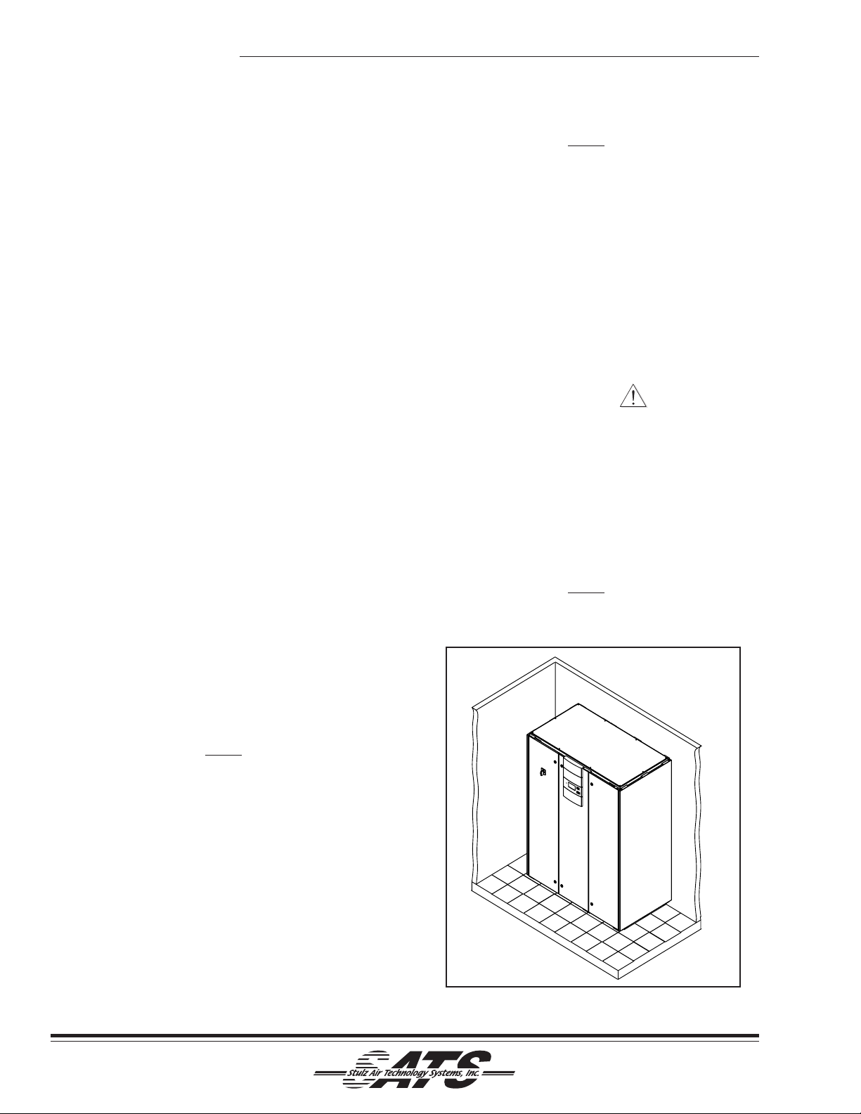
Position unit in the desired location. CyberChiller
systems are 100% front accessible, which allows the
units to be placed in a corner or between cabinetry .
(See Figure 2.)
NOTE
Allow access to the unit for routine operation,
servicing and for necessary maintenance.
NOTE
Items that have been shipped loose, such as
controllers, temperature sensors, water detectors, etc., are shipped inside the air conditioner
unless specified otherwise by the customer.
Unpack and store these items in a safe place
unless you are using them immediately .
2.2 Site Preparation
CyberChiller systems are designed with easy service
access in mind. Component access doors are located
on the front of the unit.
In order to have full service access through the front,
no permanent obstructions should be placed within 40
inches of the front of unit.
2-1
Figure 2- Typical Installation
(©October, 2006)
Page 13
CyberChiller Series Installation, Operation & Maintenance Manual
The following general requirements should be considered during installation:
NOTE
Equipment must be level to operate properly .
2.4.1 Indoor Equipment
The CyberChiller system uses a frame and panel
construction for unit rigidity and full service accessibility while the unit is mounted in place. The unit is
designed to be located directly on top of the floor or on
a raised floor installation. Ensure the mounting surface
is able to support the equipment. Before mounting the
unit, refer to the appropriate weight tables that are
provided in the installation drawing.
2.4.2 Outdoor Equipment
Install the remote condenser or fluid cooler in a secure
location where the unit cannot be tampered with and
the main power circuit breaker cannot be inadvertently
turned off. If possible, make use of terrain features
such as trees and buildings to provide a shaded
location. This will minimize the solar load on the unit.
Locate the remote condenser or fluid cooler where the
coils are not likely to draw dirt and debris into the coil
fins. The clearance around the unit should be at least
1 times (1x) the unit’s width to ensure adequate airflow
to the coil.
Secure the condenser or fluid cooler so that the
system will not move during operation. Refer to the
installation drawing for the non-charged system
weight. It is recommended that the remote condenser/
fluid cooler be mounted with field supplied vibration
mounts to reduce the amount of vibration transmitted
to the mounting surface.
Refer to the wiring diagram for electrical connections
and to the refrigeration diagram for piping details.
2.4.3 Pump Package Installation (Water Glycol Systems
Install the pump in general accordance with the piping
diagram provided with the unit. The pump should be at
least 3 feet below the height of the expansion tank.
Do not form piping loops adjacent to the pump. A void
piping very rigid lines.
If the pump will be operated at reduced capacity,
a by-pass must be provided around the pump
suction and discharge connections to prevent
damage to the pump seals. Damage would result
from insufficient liquid passing through the pump and
the heat of the pump vaporizing the brine solution due
to the motor’s heat and the friction of the impeller
housing.
It is a good idea to install a pressure gauge in the
discharge line to check the pressure.
2.4.4 Optional Equipment (Field Installed)
NOTE
Do not mount any optional equipment on unit
access doors.
2.4.4.1 Remote Display
The C6000 Microprocessor is the standard controller
supplied with the CyberChiller systems. As an option a
factory supplied control panel may be remotely
mounted. For mounting and wiring instructions, refer to
the system drawings and the supplemental manual
sent in the data package with your unit.
2.4.4.2 Remote Water De te ct or
The optional remote water detector(s) is normally
placed on the sub-floor or in a field supplied auxiliary
drain pan located beneath the unit. It may be attached
using double sided tape. Prepare surface before
installing tape. Apply t ape to the water detector and
secure in place.
(©October, 2006)
2-2
Page 14

CyberChiller Series Installation, Operation & Maintenance Manual
OCK
S
T
S
T
SSURE
(
)
S
2
C
SS
ON
SO
E
E
SIG
SS
R
S
CE
T
R
CO
OL
D
CO
R
CS
G
S
G
S
S
SO
E
CHECK
SC
R
HIG
SSURE
CH
P
SSURE
CH
.
.
S:
OU
T
2.5 Piping Connections
2.5.1 Process Supply Fluid Lines
Coolant fluid supply and return lines are connected
from the equipment being cooled to the CyberChiller
via copper sweat fittings provided in the pump section.
2.5.2 Refrigerant
2.5.2.1 Split Air Cooled Systems
Split air-cooled systems with a remote condenser will
require field refrigeration piping. (See Figure 3.) All split
systems are shipped with a dry nitrogen charge of 50
psig.
Split systems coupled with a remote condensing unit
will require a copper discharge and a copper liquid line.
All refrigeration piping should be installed with high
temperature soldered joints. Use standard refrigeration
practices for piping supports, leak testing, dehydration
and charging of the refrigeration circuits. The refrigeration piping should be isolated from the building by the
use of vibration isolating supports. T o prevent tube
damage when sealing openings in walls and to reduce
vibration transmission, use a soft flexible material to
pack around the tubes.
Clear all pipe connections of debris and prepare the
connections for soldering. Use only "L" or "K" grade
refrigerant copper piping. Be careful not to allow
solder/piping debris to get inside refrigerant lines.
Silver solder containing a minimum of 15% silver is
recommended. Dry nitrogen should be flowing through
the tubing while soldering at a rate of not less than 1-2
CFM (.03 - .06 M3/minute).
Refrigerant lines for split systems must be sized
according to the piping distance between the evaporator and the condenser. Each valve, fitting and bend in
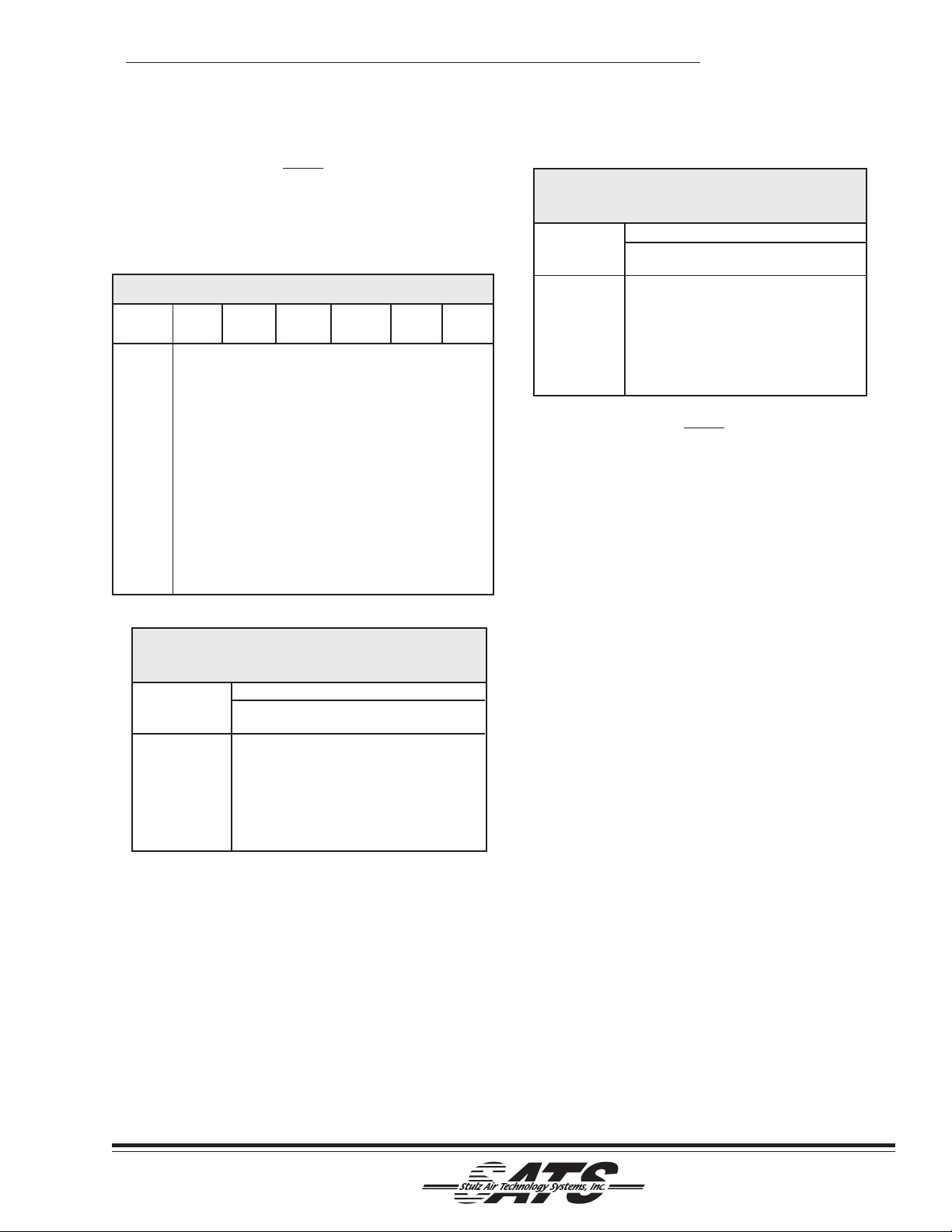
the refrigerant line must be considered in this calculation. Refer to the following charts for standard equivalent lengths, in feet, of straight pipe.
Oil traps must be included in the discharge line every
20 feet in the vertical risers and the refrigerant lines
must be sloped ¼ inch for every 10 feet in the horizontal lines to ensure proper oil return to the compressor.
An inverted trap is required on the discharge line of the
remote condenser to help prevent oil and liquid from
flooding back to the compressor.
PRE
INTERCONNECTIN
FIELD PIPING BY OTHER
NDENSE
FAN SPEE
NTR
INTERCONNECTIN
FIELD PIPING BY OTHER
NOTE
1) LOCATE AUTOMATIC AIR VENT AT HIGHEST POINT OF SYSTEM
2) PRESSURE RELIEF VALVE MUST BE PIPED TO EXIT THE CABINET
OPTIONAL
EE NOTE
Figure 3- Typical Piping Air Cooled System
RECEIVE
HRADE
ERVI
POR
H PRE
LIMIT SWIT
DRIER/STRAINE
H
ERVICE POR
HOT GA
LENOID VALV
ROTOL
HT GLA
ELECTRONI
HOT GAS BYPA
ERVICE POR
LIQUID LIN
LENOID VALV
W PRE
IMIT SWIT
EXPANSI
UALIZER LINE
TLE
2-3
(©October, 2006)
Page 15
CyberChiller Series Installation, Operation & Maintenance Manual
NOTE
In the following (3) charts, the line sizes represent the sizing for individual refrigeration circuits.
CyberChiller units have two separate pairs of refrigeration lines. (One per compressor.)
Equivalent Length (ft) of Straight Pipe
OD (In.) Globe An gle 90º 45º Tee Tee
Line Size Valve Valve Elbow Elbow Line Branch
1/2 9.0 5.0 0.9 0.4 0.6 2.0
5/8 12 6.0 1.0 0.5 0.8 2.5
7/8 15 8.0 1.5 0.7 1.0 3.5
1-1/8 2 2 12 1.8 0.9 1.5 4.5
1-3/8 2 8 15 2.4 1.2 1.8 6.0
1-5/8 3 5 17 2.8 1.4 2.0 7.0
2-1/8 4 5 22 3.9 1.8 3.0 10
2-5/8 5 1 26 4.6 2.2 3.5 12
3-1/8 6 5 34 5.5 2.7 4.5 15
3-5/8 8 0 40 6.5 3.0 5.0 17
Recommended Liquid Line Sizes
(For R-22 or R-407C Refrigerant)
Model No./ Receiver to Evaporator
Total Unit
Capacity or less or less or less
120 / 120,000 1/2 5/8 5 /8
210 / 210,000 5/8 7/8 7 /8
260 / 260,000 7/8 7/8 7 /8
320 / 320,000 7/8 7/8 7 /8
*Equivalent Ft. accounts for the linear pipe length as well as
equivalent length of Valves, Elbows & Tee’s as shown in the
previous chart.
50' 100' 150'
(Equivalent Ft.)*
Recommended Discharge Line Sizes
(For R-22 or R-407C Refrigerant)
Model No./
Total Unit
Capacity o r less or less or less
120 / 120,000 7/8 1-1/8 1 -1 /8
210 / 210,000 1-1/8 1-1/8 1-3/8
260 / 260,000 1-1/8 1-3/8 1-3/8
330 / 330,000 1-1/8 1-3/8 1-3/8
50' 100' 150'
Vertical runs are based on a tot al rise of 30 equivalent
feet. For longer sizes, individual calculations must be
made. Sizes assume the use of single risers; double
risers may be necessary .
*Equivalent Ft. accounts for the linear pipe length as well as
equivalent length of Valves, Elbows & Tee’s as shown in the
previous charts.
2.5.2.2 Water/Glycol Fluid Cooled Systems
Piping connections for the water/glycol fluid coolers
are sweat connections. (See Figure 4.) Pipe sizes
may not necessarily be the same as the unit connection. Piping should be sized to match the system
pressure drop and pump capacity and may require a
reducing fitting to match the connection size on the
pump package and CyberChiller.
Copper is adequate for closed loop systems and
ground water which is not high in mineral content and
is pH neutral. In situations where scaling could be
heavy , or where biological growth will be present, a
closed loop system is recommended. Untreated water
in the unit heat exchangers may cause, over a period
of time, a loss of heat exchange capacity due to a
mineral deposit build-up inside the exchanger. Only a
qualified service mechanic should clean these.
Equivalent Length Ft.*
NOTE
(©October, 2006)
Glycol-cooled systems with low entering fluid temperatures should have insulated piping. The recommended
ethylene glycol solution ratio is 40% glycol to 60%
water. (SA TS recommends Dowtherm SR1 manufactured by Dow Chemical Co.) Use only ethylene glycol
with inhibitors for corrosion protection.
2-4
Page 16

CyberChiller Series Installation, Operation & Maintenance Manual
T
S
UNIO
O
SS
REMO
COO
G
CO
R
CHECK
UNIO
P
SHUT-OFF
SHUT-OFF
SHUT-OFF
SHUT-OFF
SHUT-OFF
K
(
)
~
EXPANSION TAN
MUST BE INSTALLED AT THE
HIGHEST POINT IN THE SYSTEM.
TROL
FITTIN
TE DRY
LER
AQUASTA
TRAINER
FL
W BYPA
PUMP PACKAGE
N
PUM
Figure 4- Typical Piping Water/Glycol Cooled System
W ARNING
Glycol is hazardous. Consult the manufacturer's
MSDS for detailed safety information.
CAUTION
When installing and filling the water/glycol loop all
air must be bled from the piping system and the
piping system must be cleaned prior to operating
the system. Failure to do so will result in equipment problems.
2.5.3 Pump Package
2.5.3.1 Suction Side Piping
Install a concentric reducer at the pump suction
opening and make all suction piping at least one-(1)
size larger than the diameter of the suction inlet. If
necessary , install a suction strainer with a net area 2-3
times larger than the suction piping. The piping leaving
the drycooler should enter the pump suction port.
Install a ball valve in the suction line for maintenance
purposes.
WATER/GLYCOL COOLED
NDENSE
REGULATOR
N
2.5.3.2 Discharge Side Piping
Install a concentric reducer at the pump discharge
opening and make all discharge piping at least one-(1)
size larger than the diameter of the discharge outlet.
Install a check valve in the discharge line to prevent
back flow that may damage the pump on shut down.
Install a ball valve in the discharge line for maintenance
purposes.
2.6 Utility Connections
2.6.1 Main Power
The CyberChiller product offering is available in 208230 V AC single-phase or 460 VAC three-phase
configurations. It is imperative that the unit nameplate
be examined to determine the operating voltage,
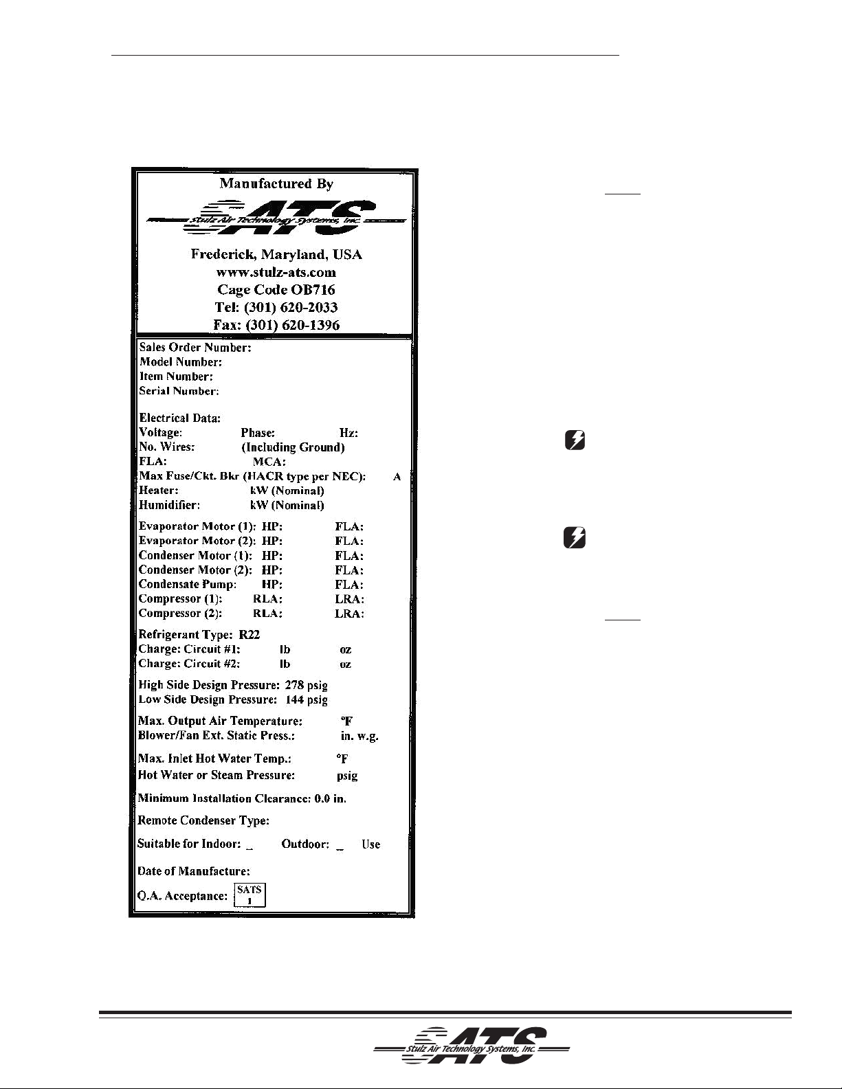
frequency and phase of the system. (See Figure 5.)
The nameplate also provides the full load amps (FLA),
the current that the unit will draw under full design
load, the minimum circuit ampacity (MCA) for wire
sizing, and the maximum fuse or HACR (Heating, Air
Conditioning, Refrigeration) breaker size (MAX FUSE/
2-5
(©October, 2006)
Page 17
CyberChiller Series Installation, Operation & Maintenance Manual
CKT BKR) for circuit protection. The unit's nameplate
is located inside the cabinet within the electrical box.
NOTE
If the nameplate states MAX FUSE/CKT BKR,
it is required to utilize fuses or HACR type circuit breakers to protect the system. Other protection devices are not allowed based upon the
product listing.
Each unit is provided with terminals for all required
field-wiring connections, (supplied by others). Refer to
the electrical schematic supplied with the unit for all
power and control field-wiring connections. It is
important to identify the options that were purchased
with the unit in order to confirm which field connections
are required.
W ARNING
High voltage is used in the operation of this
equipment. Death on contact may result if
personnel fail to observe safety precautions.
WARNING
Verify power is turned of f before making connections to the equipment.
NOTE
All wiring must conform to local and national electrical code requirements. Use of copper conductors only is required. Wiring terminations may
become loose during transit of the equipment;
therefore, it is required to verify that all wiring
terminations are secure.
It is important to verify that the main power supply
coincides with the voltage, phase and frequency
information specified on the system nameplate. The
supply voltage measured at the unit must be within
±10% of the voltage specified on the system nameplate.
A manual fused disconnect switch or HACR type
circuit breaker must be installed per local and national
electrical codes for service of equipment. Do not install
a customer supplied manual fused disconnect switch
or HACR type circuit breaker to the surface of the unit.
Figure 5- Sample Nameplate
(©October, 2006)
2-6
Page 18
CyberChiller Series Installation, Operation & Maintenance Manual
Each unit is provided with main power and control
terminal positions for connection of the field-wiring.
The opening for the conduit is located in the floor of
the cabinet. A label stating "MAIN POWER INPUT" is
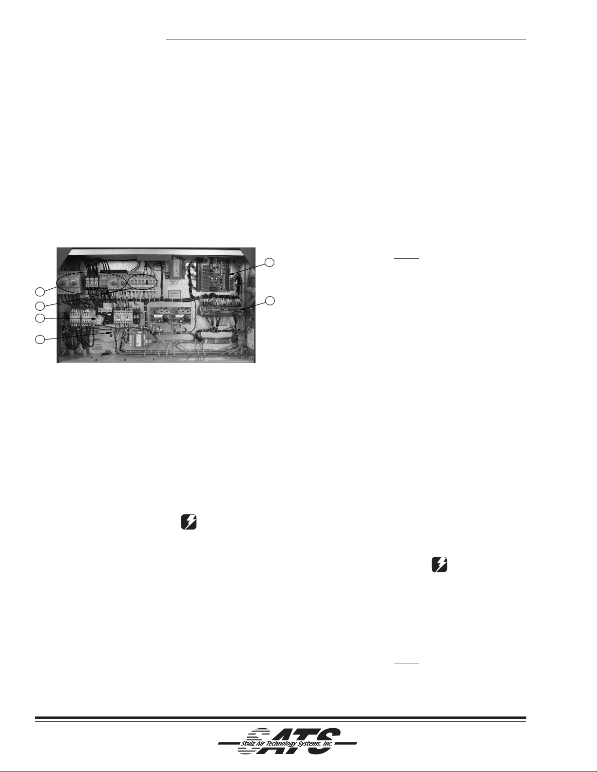
in close proximity . The main power wires are terminated at the line side of the service disconnect switch
located within the electric box. (See Figure 6.) A
separate equipment ground lug is provided within the
electrical box for termination of the earth ground wire.
T erminals are available as an interface to a dry
contact, (N.O./N.C.), relay for a remote alarm status
signal.
1
2
3
4
Figure 6- Electric Box
The number call outs in Figure 6 coincide with the
numbered items listed below .
1. Power Switches/Motor St arter Protectors
2. Control Circuit Breakers
3. Service Disconnect Switch
4. Ground Lug
5. Control I/O Board
6. Interface T erminals
CAUTION
Improper wire connections will result in the reverse rotation of the pumps and compressor (if
applicable) and may eventually result in damage to the scroll compressor. To correct this
problem, exchange any two of the incoming main
power wires at the main power circuit breaker.
Do NOT rewire the unit's individual components.
Prior to unit operation, an adequate unit-to-earth
ground must be connected to the unit.
2.6.2 Controls
Stulz Air Technology Systems offers the C6000
Microprocessor as the standard controller for the
CyberChiller system. If it is mounted on the unit
(standard), no utility connection is required. As an
option a factory supplied display may be remote
mounted. A six-conductor cable harness is provided for
interconnect wiring. Refer to the electrical drawings
supplied with your unit for details on interconnecting
field wiring.
2.6.3 Optional Equipment
5
All wiring must be provided in accordance with
local and national electrical code requirements.
6
2.6.3.1 Remote Water Detector
The optional remote water detector requires two
conductors to be wired to the control terminal board
within the unit electrical box. The wire insulation must
be rated at 600V . The water detector includes screw
type terminals for wire connections. Refer to the
supplied electrical schematic for proper wire terminations.
NOTE
2.6.4 Interconnecting Field Wiring
The following system interconnecting field wiring
sections detail the wiring required for a typical system.
Additional control conductors may be required depending on the options purchased with the equipment.
Refer to the supplied electrical drawings to determine
the total number of interconnecting conductors
required for your system. It is important to note that
the control transformer(s) supplied with the equipment
are sized and selected based upon the expected loads
for each system.
CAUTION
Do not connect any additional loads to the system control transformers. Connecting additional
loads to the factory supplied control transformer
may result in overloading of the transformer, which
will cause the transformer circuit breaker to trip.
NOTE
2-7
All wiring must be provided in accordance with
local and national electrical code requirements.
(©October, 2006)
Page 19
CyberChiller Series Installation, Operation & Maintenance Manual
COO
R
)
G
(TO
E
C
/60Hz
5V
M
O
CCO
H
(
D
)
AIN P
208-57
INTERCONNECTING FIELD
TO BE INSTALLE
WIRING
IN A
RDANCE WIT
NFPA 70, N.E.C.
MAIN POWER SUPPLY
208-575V/3PH
24VA
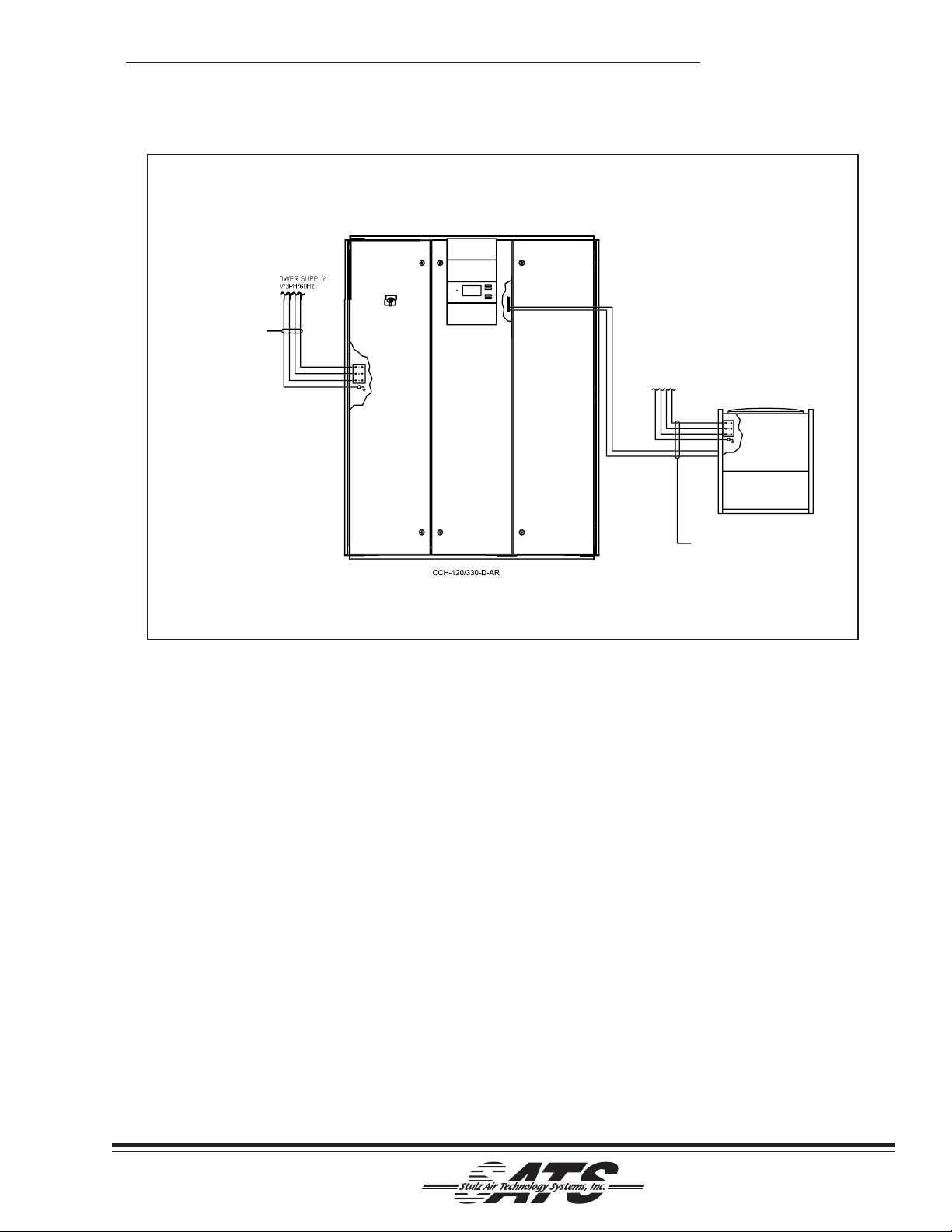
Figure 7- Interconnecting Field Wiring Remote Condenser
2.6.4.1 Air-Cooled Split System Remote
Condenser
See Figure 7. Systems equipped with a remote
condenser require field wiring between the evaporator
system and the remote condenser. Refer to the wiring
diagram supplied with the condenser (typically located
in the condenser electric box).
The installer must provide main power wiring to the
main power distribution block located within the
remote condenser control box. A separate equipment
ground lug is provided within the electrical box for
termination of the earth ground wire.
AIR
LED CONDENSE
INTERCONNECTING FIELD WIRIN
BE INSTALLED IN ACCORDANC
WITH NFPA 70, N.E.C.
2.6.4.2 Glycol Systems With Outdoor Fluid
Pump Package
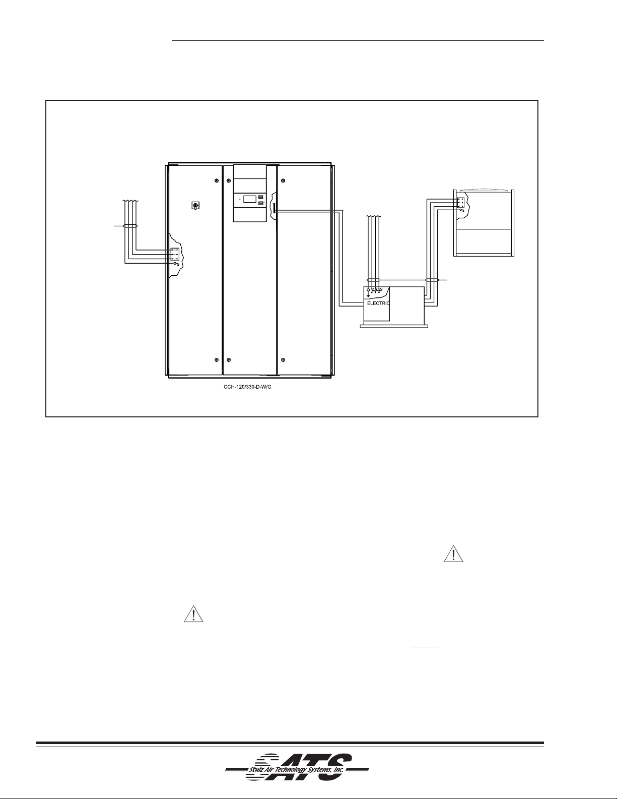
See Figure 8. Systems equipped with a glycol system
pump package require field wiring between the
drycooler unit and pump package. The installer must
wire two control conductors from the terminal board
within the drycooler to the pump package electrical
box. Refer to the supplied electrical schematic for
proper wire terminations.
The installer must also wire two control conductors
from the terminal board within the evaporator unit to
the control terminal board within the remote condenser
control box. Refer to the supplied electrical schematic
for proper wire terminations.
(©October, 2006)
2-8
Page 20
(
E
(
)
C
GPS PU
GE
OX
)
G
M
08-575V/3PH/60Hz
(
)
COOLER
/60Hz
M
CCO
H
INTERCONNECTING FIELD
(
D
)
WIRING
TO BE INSTALLE
RDANCE WIT
IN A
NFPA 70, N.E.C.
AIN POWER SUPPLY
208-575V/3PH
CyberChiller Series Installation, Operation & Maintenance Manual
AIN POWER SUPPLY
2
DRY
GLYCOL UNITS ONLY
INTERCONNECTING FIELD WIRIN
TO BE INSTALLED IN ACCORDANC
WITH NFPA 70, N.E.C.
24VA
B
Figure 8- Interconnecting Field Wiring Glycol Systems
2.7 System Settings and Adjustment s
2.7.1 Chilled Water Supply Charging
Procedures (Evaporator Side)
2.7.1.1 Pump Start-Up
Fill the system with potable water before turning the
pump on. These pumps are not self-priming, so it is
important that there is a pressure on the suction inlet.
CAUTION
Do not run the pump dry .
If the pump has no pressure on the discharge side,
leave the discharge valve partially shut to create a
back pressure in the pump so that liquid volume can
build up in the impeller housing to keep the impeller
housing from getting too hot. Make sure there is
always liquid leaving the pump, indicating that there is
flow in the pump to cool the impeller and housing. If
MP PACKA
GLYCOL UNITS ONLY
there is no flow shut the pump off immediately to
prevent damage to the pump. Check for proper rotation
of the motor observing the arrow on the side of the
impeller.
CAUTION
The pumping system of the CyberChiller is
designed for use with a positive suction head.
At no point should the system be operated for
an extended period of time with less than 5 to
10 psig at the pump inlet pressure fitting.
NOTE
The piping system must be clean prior to
operating the system
1. Connect the water source to the drain valve hose
bib.
2-9
(©October, 2006)
Page 21

CyberChiller Series Installation, Operation & Maintenance Manual
2. Open the vent valve at highest point of the system.
3. Open the water source and run until the water
solution is discharging from the vent with minimal
signs of foaming due to air in the system.
4. Allow pump to run until 30 psig is indicated on the
pressure gauge at the pump inlet fitting.
5. Ensure water side is completely filled without air
voids. Check and verify proper flow rate is obtained
before starting the compressors.
CAUTION
Extensive operation of the circulating pump
with the compressors disabled may cause
damage from the abnormally high water/glycol
temperature developed.
5. Observe the pressure on the pressure gauge
connected to the chiller pump inlet fitting. Maintain
20 to 30 psig on the pressure gauge.
CAUTION
Improper setting of the heat exchanger flow
switch may result in freezing of the heat
exchanger, and system failure not covered by
warranty. Only qualified individuals should
perform this procedure.
2.7.1.2 Strainer Cleaning
NOTE
During initial operation the “Y” strainer will trap
the majority of the particulate left in the
system as a result of various manufacturing
processes. The Strainer MUST be cleaned
every 30 minutes during the first 3 hours of
operation to ensure adequate flow of coolant.
(See below.)
1. Switch both compressors to the “OFF” position.
2. Isolate the “Y” strainer by closing isolation valves.
3. Unscrew the brass fitting from the “Y” strainer and
pull the screens out.
4. Wash the screens thoroughly to remove the
collected particulate.
6. Re-open isolation valves.
7. Resume unit operation. Repeat steps 1 – 6 every
30 minutes for first 3 hours operation.
2.7.2 Outdoor Heat Exchanger Glycol
Charging Procedures
In glycol cooled units the refrigerant system is already
charged with R-22 or R407C.
The following precautions must be observed when
installing and filling the glycol loop:
• The glycol must be mixed with water before it is
added to the system. All air must be bled from the
piping system.
• The piping system must be cleaned prior to
adding the glycol solution to the system.
• Use only water glycol solution with inhibitors for
corrosion protection.
2.7.3 R-22 Refrigerant Charging Procedures
NOTE
Refrigerant charging must be performed by a journeyman, refrigeration mechanic or an air conditioning technician.
2.7.3.1 Remote Air-Cooled Split Systems
Remote air-cooled units come equipped with a factory
dry nitrogen holding charge, which must be removed
before piping and charging the unit.
PREPARING SYSTEM FOR CHARGING
1. Once all connections have been made, pressurize
the system to 150 psig with dry nitrogen. Leaks
may be detected by observing the standing
pressure.
2. After ensuring there are no leaks, relieve pressure
and evacuate the system. Pull a vacuum of 50
microns or less using the suction and discharge
service ports and the service port of the receiver (if
applicable). Hold the vacuum for 2 hours. Ensure
no portion of system has been isolated from the
evacuation process (liquid, suction or discharge
lines).
5. Reinstall the screens in the strainer housing and
replace the brass fitting.
(©October, 2006)
2-10
Page 22
CyberChiller Series Installation, Operation & Maintenance Manual
CAUTION
A proper vacuum must be drawn on the refrigerant system prior to charging. If this is not done
the refrigerant will combine with the moisture in
the pipes to form an acid that will eventually
cause compressor failure.
FINE TUNING THE SYSTEM CHARGE
2.7.3.2 -20ºF Variable Speed Control
The following instructions are for charging systems
with condenser fan cycling or variable speed control
using R-22 refrigerant.
1. Bleed air from hoses and "break" the system
vacuum by supplying R-22 vapor. Supply R-22
vapor until the pressure is raised to about 50
psig. This small holding charge allows the low
pressure switch to “make” throughout the process of fine tuning the system charge
W ARNING
Do not add liquid R-22 refrigerant to the
suction side of the system.
2. Start the system and use the microprocessor
controller to lower the supply water temperature
set-point 3-5°F below actual water temperature.
This will ensure the cooling mode stays on during
the charging procedure.
CAUTION
An adequate heat load must be supplied to the
unit to ensure a proper charge.
3. Supply R-22 vapor to the suction port until the
liquid line sight glass is cleared of all bubbles.
4. After the unit has stabilized, the liquid line sight
glass should be clear and the discharge pressure
should be a minimum of 200 psig. A superheat
reading should be taken 6 inches from the compressor, with the temperature-measuring device
being well insulated. The superheat should be
approximately 10-12 ºF .
sub-cooling temperature should be approximately
10-20 ºF .
NOTE
Under cold climate conditions it is recommended
to do the following:
6. Block off the intake air to the condenser with
cardboard (or reduce the water glycol flow) until a
constant discharge pressure (225-280 psig) can
be obtained. This will lower the possibility of
overcharging and avoid the occasional bubbles
that may appear in the sight glass during fan
cycling.
7. Ensure the crankcase heater is operational by
checking the amperage.
CAUTION
Remove the blockage to the air intake of the
condenser (or restore the water/glycol flow).
9. Fill out applicable blocks of Warranty Registration
and Start-Up Checklist.
2.7.4 R407C Refrigerant Charging Procedures
R-407C is a blended refrigerant recognized for being
safer for the environment. Refrigerants that are multicomponent blends have component parts with different
volatilities that result in a change in composition and
saturation temperature as evaporation and condensation occur. Typically the composition of R-407C vapor
is different than that of R407C liquid within a contained system. The composition of liquid R-407C
refrigerant remains relatively constant, however, the
refrigerant vapor tends to separate into its component
parts even when circulating. When charging a system
using blended refrigerants, it is essential that the
composition of the refrigerant is maintained. To
ensure correct composition, introduce R-407C into the
system in liquid form rather than vapor form. Cylinders
which are not provided with dip tubes should be
inverted to allow only liquid refrigerant to charge the
system. Keeping the temperature of the cylinder
below 85°F will help to maintain the correct refrigerant
composition while the cylinder is emptied.
5. A sub cooling reading should be taken on the
output side of the condenser, with the temperature-measuring device being well insulated. The
2-11
(©October, 2006)
Page 23
CyberChiller Series Installation, Operation & Maintenance Manual
CAUTION
POE oil is used in systems with R-407C
refrigerant. POE oil quickly absorbs moisture
when exposed to air. High POE oil moisture
levels react with refrigerant to form acid, which
results in system contamination. Keep entire
system sealed as much as possible and
minimize exposure of POE oil to outside air.
Familiarize yourself with the charging procedures discussed in section 2.7.3 of this
manual. Instead of adding R-22 vapor to the
suction port as described under “Preparing
System For Charging”, the initial charge will
be performed by introducing R-407C liquid to
the discharge side of the compressor.
PREPARING SYSTEM FOR CHARGING
1. With all the system piping connections made,
perform a dry nitrogen leak detection test on the
system. Using dry nitrogen only, pressurize the
system to 150 psig. Since there is no refrigerant
in the system to detect, leaks may be detected
by observing the standing pressure.
2. After ensuring there are no leaks, evacuate the
system to 50 microns and hold the vacuum for 2
hours.
3. Break the vacuum by supplying R-407C liquid to
the discharge port near the compressor until the
pressure is raised to about 50 psig. This small
holding charge allows the low pressure switch to
“make” through the process of fine tuning the
system charge.
FINE TUNING THE SYSTEM CHARGE
4. Disconnect the refrigerant cylinder from the
discharge side of the compressor and connect it
to the suction side.
5. Start the system and use the microprocessor
controller to lower the supply water temperature
setpoint 3-5°F below actual water temperature,
ensuring cooling remains on as the unit is
charged.
6. Allow the discharge pressure to rise to 225-280
psig and hold it constant. On cool days it may be
necessary to restrict the airflow across the
condenser (or reduce the water glycol flow), to
raise the pressure.
7. Slowly meter R-407C liquid refrigerant through the
suction side while watching the sight glass to clear
of bubbles.
CAUTION
Add liquid refrigerant slowly to prevent the refrigerant
oil from “washing out” of the compressor.
8. While monitoring the sight glass, take a subcooling temperature reading on the output side of
the condenser. The sub-cooling temperature
should be 10-12°F.
9. If necessary, add liquid refrigerant to maintain
adequate sub-cooling temperature.
10. Take a superheat reading on the suction line 6"
from the compressor. The superheat should be 1220°F.
2.7.5 High/Low Pressure Limit Switch
CyberChiller units utilizing thermal expansion valves
are equipped with hermetically sealed high-pressure
and low-pressure switches. These switches are preset
by the manufacturer and cannot be adjusted. The high
pressure switch will open the control circuit to disengage power to the compressor contactor if the
discharge pressure rises above a specific pressure.
The high pressure switch also triggers an alarm signal
at the controller. T o restore operation of a compressor
after shut down due to high or low pressure, re-set the
alarm at the remote panel. If a compressor was
disabled due to high pressure conditions, a manual
reset of the high pressure safety switch is also
required. The high-pressure switch opens at 410 psig
and has a manual reset.
The Low pressure switch will open the control circuit
to the microprocessor digital input to disengage power
to the compressor contactor if suction pressure drops
below a specific pressure. The microprocessor will
ignore the absence of this signal during the cold start
delay period after starting of a compressor . Should
this signal continue to be absent or open after the
cold start period, the affected compressor will be shut
down with an alarm indication at the controller. Th e
low-pressure switch opens at 10 psig (± 4) and closes
at 32 psig (± 5) and has an automatic reset.
(©October, 2006)
2-12
Page 24
CyberChiller Series Installation, Operation & Maintenance Manual
2.7.6 Head Pressure Controls
2.7.6.1 Air-Cooled Systems
2.7.6.1.1 Condenser Fan Speed
Remote air-cooled condensers use variable speed
condenser motor control to maintain head pressure.
The variable speed motor is located closest to the
header end of the condenser. The fan speed control is
a continual modulation of the motor's speed. As the
condenser discharge pressure rises, the fan speed
increases, cooling the condenser which lowers the
discharge pressure. The controller is mounted in an
electrical box for field installation or could be prepackaged with the outdoor condenser . Mount the
condenser control box on the header end of the
condenser. The fan speed controller requires no
adjustments.
Ensure the wiring to the condenser is in accordance
with appropriate codes and the electrical schematic.
On systems with more than one fan on the condenser,
the remaining motors cycle on and off through additional thermostat(s).
2.7.6.2 Water/Glycol-Cooled Systems
2.7.6.2.1 Head Pressure Regulating Valve
In a water/glycol condenser, condensing temperature
is maintained by the liquid flowing through a regulating
valve and then into a brazed plate liquid-cooled
condenser. The regulating valve opens to increase
liquid flow as the pressure rises (or closes as the
refrigerant pressure falls). The regulating valve is
factory set for the correct condensing temperature
however, it can be adjusted to increase or decrease
the condensing temperature as follows:
Head pressure regulating valves are available in 2-way
or 3-way configurations. 3-way valves are available with
pressure ratings of 150 and 300 psig. The location and
method for adjusting the valves for condensing pressure differs with the valve types. To increase the
condensing temperature, decrease water/glycol flow.
T o decrease the condensing temperature, increase the
water/glycol flow. A directional arrow is stamped on the
metal housing of the valve stem.
2.7.7 Thermal Expansion Valve
CyberChiller units utilize a thermal expansion valve
(TEV) to control the flow of refrigerant entering the
evaporator in order to maintain a constant superheat of
the refrigerant vapor at the outlet of the evaporator.
Superheat is the difference between the refrigerant
vapor temperature and its saturation temperature at
that pressure. By controlling superheat, the TEV
keeps nearly the entire evaporator surface active while
not permitting liquid refrigerant to return to the compressor.
The standard superheat is factory set at 12-20°F and
should not need adjustment. If adjustment should be
required, remove the cap from the valve. Turn the
adjusting stem clockwise to increase the superheat
and counter clockwise to decrease the superheat.
2.7.8 Hot Gas Bypass
The hot gas bypass system provides some modulated
capacity control and freeze protection. The hot gas
bypass system consists of a discharge bypass valve
that allows some hot gas from the compressor
discharge line to flow directly to the evaporator, in
order to maintain the fluid leaving temperature.
The hot gas bypass system also provides freeze
protection for the evaporator coil by limiting the
minimum refrigerant pressure, thereby preventing the
surface temperature of the evaporator coil from dropping into the freezing range.
The hot gas bypass valve is automatically controlled
by the Chiller’s unit mounted controller. The hot gas
bypass valve will begin to open, allowing hot gas
refrigerant to enter the evaporator once the leaving
water temperature falls to the leaving water temperature setpoint.
2-13
(©October, 2006)
Page 25
CyberChiller Series Installation, Operation & Maintenance Manual
2.8 Refrigerant Characteristics
2.8.1 Pressure/Temperature Settings
The following chart is provided to assist with the
normal settings of the system for R-22 and R407C
refrigerant. Where applicable, minimum and maximum
settings are given along with normal operating pressures.
Pressure/T emperature Settings For R-22 & R407C
Normal Min. Max.
Sub-cooling°F 10 5 20
Superheat°F 15 10 20
Condensing T emperature Air-Cooled°F 125 105 140
Condensing Temperature Water-Cooled°F 105 105 140
Condensing T emperature Glycol-Cooled°F 130 105 140
Suction Pressure (psig) 70 58 84
Opens Closes
Low Pressure Switch (psig) 10 32
High Pressure Switch (psig) 410 Manual Reset
2.8.2 Saturated Refrigerant Pressure Tables
The following refrigerant vapor pressure tables are
provided for reference.
R-22 Refrigerant
Temp. Pressure
(°F) (psig)
20 43.2
22 45.5
24 47.8
26 50.2
28 52.6
30 55.1
32 57.7
34 60.4
36 63.1
38 65.9
40 68.7
42 71.7
44 74.7
46 77.8
48 81.0
50 84.2
55 92.7
60 102
65 111
70 122
75 132
80 144
85 156
90 168
95 182
100 196
105 210
110 226
115 242
120 260
125 278
130 296
135 316
140 337
R-407C Refrigerant
Temp. Pressure
(°F) (psig)
Superheat
20 37.0
22 39.1
24 41.3
26 43.6
28 46.0
30 48.4
32 50.9
34 53.5
36 56.2
38 58.9
40 61.7
42 64.6
44 67.6
46 70.7
48 73.8
50 77.1
Sub-cooling
95 206
100 222
105 239
110 257
115 275
120 294
125 315
130 336
135 358
140 381
Dew
Point
(Saturated
Vapor)
Bubble
Point
(Saturated
Liquid)
(©October, 2006)
2-14
Page 26
CyberChiller Series Installation, Operation & Maintenance Manual
3.0 START-UP/COMMISSIONING
3.1 Operation
For new installations, ensure the unit is ready to
operate by going through the Checklist for Completed
Installation, located in Appendix A, prior to start-up.
NOTE
A W arranty Registration and S tart-Up Checklist
is provided with the unit data package. It should
be completed during start-up and sent to SA TS.
This checklist should be used as a guideline for
items that need to be confirmed during start-up.
Start-up must be performed by a journeyman, refrigeration mechanic or an air conditioning technician.
3.2 Step by Step Start-Up Instructions
1. Replace all equipment removed prior to performing
start-up checks.
2. Apply power to start the CyberChiller system at
the main power disconnect switch.
NOTE
The compressor(s) may have a time delay on start-up.
Both refrigeration circuits must be tested at start-up.
There are several ways to force the second circuit
into operation. Refer to the separate controller operation instructions sent with your unit in the data package.
3. T est cooling operation by adjusting the leaving fluid
temperature setpoint. The compressor should
come on and the chilled water supply should
gradually drop in temperature.
3.2.1 Operational Description
3.2.1.2 Compressor
1. Compressor starts.
2. The compressor takes low pressure, low temperature gas and compresses it to a high temperature,
high pressure gas.
3. The refrigerant then flows to the condenser coil.
The high temperature, high-pressure gas from the
compressor is cooled by the flow of water/glycol/
air through the condenser coil and is changed into
a low temperature, high-pressure liquid.
4. The low temperature, high-pressure liquid refrigerant then flows to the receiver. The receiver acts as
a storage tank for the liquid refrigerant that is not
in circulation.
5. The refrigerant drier/strainer removes any moisture
(water vapor) or impurities that may be carried by
the liquid refrigerant.
6. The refrigerant then flows through the liquid sight
glass. This device indicates the presence of
moisture and state of refrigerant in the system.
7. The liquid line solenoid valve controls the flow of
refrigerant before going to expansion valve, which
controls the amount of liquid refrigerant to the heat
exchanger. The expansion valve senses the
temperature and pressure of the refrigerant as it
leaves the heat exchanger. By use of a sensing
bulb and an external equalizer line the valve
constantly adjusts the flow of liquid refrigerant to
the heat exchanger.
8. As the liquid refrigerant leaves the expansion valve
it enters the heat exchanger. The evaporation of
the liquid refrigerant within the heat exchanger
removes heat from the water coolant.
9. The refrigerant gas is then drawn back to the
compressor and the cycle is repeated.
10. Hot gas from the compressor discharge line is
injected into the inlet of the heat exchanger by the
hot gas bypass regulator valves. The system
controller signals the hot gas regulator valves to
proportionally vary the rate of hot gas being
injected into the inlet of the heat exchanger as a
function of the supply coolant temperature sensed.
The hot gas will mix with the refrigerant from the
expansion valve. The expansion valve will meter
the flow of liquid refrigerant as needed to maintain
super heat to approximately 9° - 1 1°F.
1 1. The hot gas valve(s) act together with the expan-
sion valve(s) to control the temperature of the
supply coolant.
3.2.1.3 Coolant System
The water coolant system is a closed loop re-circulating system. The pressurized supply coolant flows
through the electronics equipment removing heat and
then is returned to the expansion tank inside the
CyberChiller. The fluid is pumped from the expansion
tank through the system heat exchanger where heat is
removed from the fluid. Af ter cooling, the fluid is re-
3-1
(©October, 2006)
Page 27
CyberChiller Series Installation, Operation & Maintenance Manual
supplied to the equipment. The flow switch senses the
coolant flow in the system. When the pump is operating, the coolant flow in the piping actuates the flow
switch. The switch will signal the system controller to
disable compressors and expansion valves and close
the hot gas valves if the coolant flow rate drops.
NOTE
During initial operation the “Y” strainer will trap the
majority of the particulate left in the system as a result
of various manufacturing processes. The strainer
MUST be cleaned every 30 minutes during the first 3
hours of operation to ensure adequate flow of coolant.
3.2.1.4 Water/Glycol Outdoor Fluid Cooler
On a call for cooling the dry contacts on the drycooler
control relay in the CyberChiller’s electric box close
the 24 V AC circuit from the “powered pump package”
and turn on the drycooler and pump.
An Aquast at cycles the dry cooler fan(s) on and off to
maintain an 85°F glycol temperature. As the glycol
temperature rises above 85°F the aquastat starts
cycling the drycooler fan ON to maintain 85°F glycol
temperature.
3.3 Microprocessor Controller Programming
The microprocessor controller is factory programmed
based on the optional features selected. Most applications require no field start-up or program adjustment
beyond setting the current date and time. Separate
operating instructions for the controller have been sent
with your unit, including each feature's factory "default"
setting and the available adjustment range, if applicable.
3.2.1.4.1 Dual Pump Packages
A field installed flow switch (shipped loose from the
factory) must be installed in the main glycol line. If
flow is not established the flow switch closes the 24
V AC control circuit to a switch over relay and turns off
the primary pump contactor after a time delay , and
turns on the secondary pump.
The manual Primary/Secondary switch is mounted
through the side of the pump package electric box.
Normally the switch is in the “Primary” position which
allows the controller to rotate the pumps (auto switch).
Switching to the “Secondary” position manually
overrides the primary pump control and only the
secondary pump will operate. While in the “Secondary”
position the pump package will also auto-switch to the
primary pump in the event of a loss of coolant flow.
(©October, 2006)
3-2
Page 28
CyberChiller Series Installation, Operation & Maintenance Manual
4.0 MAINTENANCE/REPAIRS
4.1 Periodic General Maintenance
Systematic, periodic general maintenance of the
CyberChiller unit is recommended for optimum system
performance. General maintenance should include,
but is not limited to the following: tightening electrical
connections, cleaning the interior of the unit, inspecting the unit’s components visually . Checking level of
refrigerant and ensuring no moisture is in the refrigerant.
Use copies of the Periodic General Maintenance
Checklist in this manual, (see Appendix A), to record
periodic general maintenance inspections. For
assistance, contact the SATS Product Support Group.
Ensure adherence to all safety statements while
performing any type of maintenance.
W ARNING
Turn off power to the unit at the main power disconnect switch unless you are performing tests
that require power. With power and controls energized, the unit could begin operating automatically at any time.
Hazardous voltage will still be present in the
CyberChiller and condenser or dry cooler even with the
unit turned off at the control panel. To isolate the unit
for maintenance, turn off power at the main power
disconnect switch.
Always disconnect main power prior to performing any
service or repairs. To prevent personal injury, st ay clear
of rotating components because automatic controls
may start them unexpectedly .
This unit employs high voltage equipment with rotating
components. Exercise extreme care to avoid accidents and ensure proper operation.
4.1.1 General
• Clean accumulations of dust and dirt from all
interior and exterior surfaces. (Quarterly)
4.1.2 Compressor
The refrigerant compressor and its drive motor are
hermetically sealed. The compressor crankcase has a
lifetime supply of oil and the drive motor has permanently lubricated sealed bearings. Check the refrigerant charge using the sight glass while the unit is
running. If low on charge, check for refrigerant leaks.
W ARNING
Phosgene, a deadly, poisonous gas, is generated when refrigerant is exposed to flame. Always ensure adequate ventilation during refrigeration repairs.
This equipment should be serviced and repaired by a
journeyman or a qualified refrigeration technician only .
Always recover all refrigerant prior to any system
repairs, failure to do so may result in system over
pressurization and rupture.
4.1.3 Outdoor Condenser/Fluid Cooler
Maintenance access to the condenser, (remote air
cooled units) or dry cooler , (glycol cooled units) is
through one or two removable panels (depending on
model). Examine the areas around the air inlet and
outlet grills, fans, motors and coils. Use a vacuum
cleaner with a soft bristle brush to clean dirt from
components. Clean the coil of all debris that will inhibit
airflow. This can be done with a sof t brush and compressed air or with a commercial coil cleaner. Check
for bent or damaged coil fins and repair as necessary .
Do not permit snow to accumulate on or around the
condenser or dry cooler in the winter. Check all
refrigerant lines and capillaries or coolant lines for
vibration isolation and support as necessary . Check all
refrigerant and coolant lines for signs of leaks.
• Check the “Y” strainer by removing the screen and
checking for accumulations of particulate. Clean as
required. (Monthly)
• Examine all wiring for signs of chafing, loose
connections or other obvious damage. (Quarterly)
• Examine brackets, motor mounts and hardware for
loose or missing parts or other damage. (Quarterly)
4-1
(©October, 2006)
Page 29
CyberChiller Series Installation, Operation & Maintenance Manual
4.2 Troubleshooting
WARNING
Turn off all power to the unit before conducting any troubleshooting procedures, unless the procedure specifically requires the system to operate. Keep hands, clothing and tools clear of the electrical terminals and
rotating components. Ensure that your footing is stable at all times.
SYMPTOM PROBABLE CAUSE RECOMMENDATION
Unit Fails to Start a. Incorrect phasing or voltage. Correct phase or voltage input.
b. Power failure. Check power source, power inlet and
fuses. Check control cables and
connections.
c. Overload protection tripped. Check for cause of overload and re-set
circuit breaker(s) or motor starter(s).
Suction Pressure T oo Low a. Loss of refrigerant (bubbles in Locate leak and repair . Recharge
sight-glass). system.
b. Expansion valve stuck or obstructed Remove and clean or replace valve.
(short cycle or continuous running).
c. Clogged drier/strainer (feels cold). Replace with new drier/strainer.
Evaporator Coil Ices a. T emperature setting too low Increase temperature setpoint.
b. Low refrigerant charge. Find leak, repair and recharge system.
c. Low water flow rate Increase flow rate
Pump Fails to Start a. Power failure. Check main voltage power source
input cable.
b. Control transformer circuit Check for short circuit or ground fault;
breaker tripped. if none reset circuit breaker.
c. Defective contactor . Repair or replace.
d. Motor starter protector tripped. Reset motor starter protector and check
amperage of motor . Compare to setting
on motor circuit controller and adjust to
FLA.
Control is Erratic Wiring improperly connected or Check wiring against schematic
broken. diagram.
(©October, 2006)
4-2
Page 30
CyberChiller Series Installation, Operation & Maintenance Manual
SYMPTOM PROBABLE CAUSE RECOMMENDATION
Condenser Pressure a. Non-condensable gas or air in the Recover system and recharge. Install
too High system. new drier/strainer.
b. Condenser air intake is blocked. Remove debris and clean condenser.
c. Overcharge of refrigerant. Reclaim excess refrigerant from system.
d. Condenser fan not operating. Check pressure/temperature operating
switches and motor. Replace as needed.
e. Condenser pressure regulating Adjust to obtain correct pressure.
valve setting too high.
3. Air in system - bleed system.
4. Check all strainers and clean if
needed.
Condenser Pressure a. Loss of refrigerant (indicated by Locate and repair leak. Recharge
too Low bubbles in sight glass). system.
b. Condenser fan controls not set Adjust or repair controls.
properly.
Noisy Compressor a. Expansion valve stuck in open Ensure feeder bulb is tight on suction
position (abnormally cold suction line). line. Check operation and superheat.
b. Broken compressor valve Replace compressor.
(compressor knocking, suction
pressure rises faster than 2lbs/min
after shutdown).
c. Worn or scarred compressor Replace compressor .
bearings.
d. Liquid slugging. System overcharged. Reclaim excess
refrigerant.
e. Scroll compressor not properly Phase correctly at main power source.
phased. DO NOT REWIRE COMPRESSOR.
Head Pressure T oo High a. Low condenser airflow . (Indicated by Open air passages. Clean coil. Check
excessive warm air leaving the condenser fan(s).
condenser fan).
4-3
b. Air or other non-condensible gas Reclaim system and recharge. Install a
in system new drier strainer.
c. Overcharge of refrigerant. Reclaim excess refrigerant from system.
d. Condenser/drycooler fans not on. Check main voltage power source to unit.
(©October, 2006)
Page 31
CyberChiller Series Installation, Operation & Maintenance Manual
SYMPTOM PROBABLE CAUSE RECOMMENDATION
Head Pressure is too Low a. Loss of refrigerant (indicated by Repair leak and recharge system.
bubbles in the sight glass).
Suction Pressure too Low a. Expansion valve stuck in the open Repair or replace valve.
position (indicated by abnormally cold
suction line).
b. Low charge, flash gas in liquid line Repair leak and recharge system.
(indicated by bubbles in sight glass).
c. Clogged drier/strainer (feels cool to Replace drier/strainer.
the touch).
d. Obstructed expansion valve (indicat Replace valve.
ed by loss of capacity).
e. Loss of control fluid from expansion Replace valve or control head.
valve control head (indicated by
bubbles in the sight glass).
Compressor Fails to Start a. T emperature setpoint too high. Adjust to desired temperature.
b. Compressor internal protector Check compressor for short circuit or
is open. ground.
c. Complete loss of refrigerant charge Locate and repair leak. Recharge
(low pressure safety switch). system.
d. Condenser pressure too high (high Check condenser for obstructions.
pressure safety switch).
e. Minimum off time has not expired. Wait for time to expire.
System Short of Capacity a. Low refrigerant (indicated by Check for leaks Repair and recharge
bubbles in sight glass). system.
b. Expansion valve stuck or Remove valve and clear obstruction or
obstructed (short cycling or replace valve.
continuous running).
c. Clogged drier/strainer (feels cold). Replace with new drier/ strainer.
Compressor Short Cycles a. Low line voltage causing Check power source for cause of low
compressor to overheat. line voltage.
b. Reduced flow rate. Check pump and strainer.
(©October, 2006)
c. Lack of refrigerant Check for leak. Repair and recharge
system.
4-4
Page 32
CyberChiller Series Installation, Operation & Maintenance Manual
4.3 Field Service
It may be necessary to perform repairs on the refrigeration system. If field repairs are necessary , the
following procedures apply:
NOTE
Do not attempt to make repairs without the
proper tools.
4.3.1 Leak Detection
Several methods can be used to detect a leak in the
refrigeration system. The most modern and easiest
method is to use an electronic leak detector. Follow
the manufacturer’s directions and any leak can be
quickly located. A second method is to use soap
bubbles. Apply a solution of soapy water with a brush
or sponge to the joints and connections in the refrigeration lines. A leak in the lines will cause bubbles to
form.
NOTE
Halogen leak detectors are ineffective with R407C refrigerant because unlike R-22 refrigerant, R-407C does not contain chlorine.
4.3.2 Leak Repair
When a leak is located, properly reclaim the remaining
refrigerant charge before attempting repairs. Adjacent
piping must be thoroughly cleaned by removing all
paint, dirt and oily film. Use wire brush, sandcloth or
sandpaper and wipe the area with clean, dry cloths.
Protect nearby parts from heat damage by wrapping
with water-soaked cloths
4.3.3 Refrigerant Piping
When replacing components within the cabinet of the
unit, the following consumable materials are recommended: Use Silfos alloy for copper-to-copper (piping
discharge or suction line repairs). Silver solder (StaySilv #45) and flux are to be used on copper-to-brass
or copper-to-steel repairs. For liquid line repairs at the
drier, strainer, sight glass, or expansion valve, use a
95 % tin to 5 % antimony solder with flux.
When component replacement is complete, remove
all traces of flux. Af ter any repair , pressure check the
system, checking for leaks prior to recharging the
system.
4.3.4 General Common Repairs/
Component Replacement
4.3.4.1 Compressor Failure
The compressor is the most important component of
the air conditioner. Numerous safety devices are
provided to protect the compressor from failing.
If a compressor failure has occurred, determine
whether it is an electrical or a mechanical failure. An
electrical failure will be indicated by the distinct
pungent odor once the system has been opened. If a
burnout has occurred, the oil will be black and acidic.
A mechanical failure will have no burned odor and the
motor will attempt to run, an abnormal or excessive
noise may be present.
An analysis of the oil is the only way to ensure the
proper procedure for cleaning the refrigerant system.
Acid test kits are available from several manufacturers for measuring the acid level in the oil. These are
capable of making accurate acid measurements, but
if they are not available, a check of the oil by sight
and smell can give a quick indication if contamination
remains in the system. Since refrigeration oils vary in
color, a sample of the new oil in the replacement
compressor should be removed prior to installation and
sealed in a small glass bottle for comparison purposes. If the oil has been exposed to refrigerant, the
bottle should not be tightly capped, since the residual
refrigerant may create a high pressure if tightly sealed
and exposed to high temperature.
CAUTION
Avoid touching or contacting the gas and oil with
exposed skin. Severe burns will result. Use long
rubber gloves in handling contaminated parts.
All electrical connections should be checked to be
sure that they are tight and properly made. Check all
circuit breakers, contactors and wiring. The contactor
should be examined and replaced if contacts are worn
or pitted.
If there is acid in the oil, there has been an electrical
failure which has caused the compressor motor to
burn out. The acid diffuses throughout the refrigeration
system and must be removed by using a burnout filter
kit before a new compressor is placed in service. Not
only must the compressor be replaced, but also the
entire refrigeration circuit must be cleaned of the
4-5
(©October, 2006)
Page 33
CyberChiller Series Installation, Operation & Maintenance Manual
harmful contaminants left by the burnout. See section
4.3.4.1.2 (Burn-Out/Acidic Cleanup) for the proper
cleaning procedure.
CAUTION
Damage to a replacement compressor caused
by improper system cleaning constitutes abuse
under the terms of the warranty . This will VOID
THE COMPRESSOR WARRANTY. Always consult the factory prior to replacing the compressor.
If there is no acid in the oil, there has been a mechanical failure. See section 4.3.4.1.1 (St andard Cleanout)
for the proper cleaning procedure.
CAUTION
POE oil is used in systems with R-407C refrigerant. If a replacement compressor is provided,
ensure that it is filled with POE oil before installing.
4.3.4.1.1 Standard Cleanout Procedure
CAUTION
Avoid touching or contacting the gas and oil with
exposed skin. Severe burns will result. Use long
rubber gloves in handling contaminated parts.
NOTE
Cleaning operations must be performed by a journeyman, refrigeration mechanic, or air conditioning technician.
1. Turn off power to the unit at the main power
disconnect switch.
2. Remove the burned-out compressor and install the
new compressor.
3. Remove the liquid line drier and install an oversized liquid line filter-drier (one size larger than the
normal selection size).
4. Evacuate the system according to standard
procedures. Normally , this will include the use of a
high-vacuum pump and a low-vacuum micron
gauge for measuring the vacuum obtained.
5. Recharge the system.
6. Turn on the power at the main power disconnect
switch and start the system.
4.3.4.1.2 Burn-Out/Acidic Cleanup Procedure
NOTE
Cleaning operations must be performed by a journeyman, refrigeration mechanic, or air conditioning technician.
1. These systems should be cleaned using the
suction line filter-drier method.
2. Turn off power to the unit at the main power
disconnect switch.
3. Remove the burned-out compressor and install the
new compressor.
4. Install a suction line filter-drier designed for acid
removal.
5. Remove the liquid line drier and install an over-
sized liquid line filter-drier (one size larger than the
normal selection size).
6. Check the expansion valve, sight glass and other
controls to see if cleaning or replacement is
required.
7. Evacuate the system according to standard
procedures. Normally , this will include the use of a
high-vacuum pump and a low-vacuum micron
gauge for measuring the vacuum obtained.
8. Recharge the system through the access valve on
the suction line filter-drier.
9. Turn on power at the main power disconnect
switch and start the system.
10. The permanently installed suction line filter-drier
permits small-system cleanup to be completed in
one service call. The pressure drop across the
suction line filter-drier should be measured during
the first hour of operation. If the pressure drop
becomes excessive, the suction line filter-drier
should be replaced (See Sporlan Bulletin 40-10, for
maximum recommended pressure drop (PSI) for
suction line filter drier).
1 1. In 24 hours, take an oil sample. Observe the color
and test for acidity . If the oil is dirty or acidic,
replace the suction line filter-drier.
12. In 2 weeks, examine oil to determine if another
suction line filter-drier change is necessary .
(©October, 2006)
4-6
Page 34
CyberChiller Series Installation, Operation & Maintenance Manual
5.0 PRODUCT SUPPORT GROUP
SA TS provides to its customers a Product Support
Group (PSG) which not only provides technical
support and parts but the following additional services,
as requested: performance evaluations, start-up
assistance and training.
5.1 Technical Support
The SA TS Product Support Group (PSG) is dedicated
to the prompt reply and solution to any problem
encountered with a unit. Should a problem develop
that cannot be resolved using this manual, you may
contact PSG at (240) 529-1399 Monday through
Friday from 8:00 a.m. to 5:00 p.m. EST . If a problem
occurs after business hours, dial the page number
(301) 414-4514 and follow the steps below:
1. Wait for the dial tone.
2. Dial your telephone number (including area
code).
3. Press the pound (#) key .
A written (or faxed) purchase order is required on
warranty parts and must be received prior to 12:00
p.m. for same day shipment. The purchase order must
contain the following items:
• Purchase Order Number
• Date of Order
• SA TS S tated Part Price (obtained from PSG)
• Customer Billing Address
• Shipping Address
• Customer's T elephone and Fax Numbers
• Contact Name
• Unit Model No., Serial No. & SA TS Item No.
The customer is responsible for the shipping cost
incurred for shipping the defective part(s) back to
SA TS. Return of defective p art(s) must be within 30
days at which time an evaluation of the part(s) is
conducted and if the part is found to have a manufacturing defect a credit will be issued.
4. Wait for a busy signal.
5. Hang up the telephone.
One of our service technicians will return your call.
When calling to obtain support, it is vital to have the
following information readily available, (information is
found on unit's nameplate):
• Unit Model Number (CCH-XXX-X-XX)
• SA TS Item Number (123456)
• Unit Serial Number (1234567)
• Description of Problem
5.2 Obtaining Warranty Part s
Warranty inquires are to be made through the Product
Support Group (PSG) at (240) 529-1399 Monday
through Friday from 8:00 a.m. to 5:00 p.m. EST. A
service technician at SA TS will troubleshoot the
system over the telephone with a field service technician to determine the defect of the part. If it is determined that the part may be defective a replacement
part will be sent UPS ground. If the customer requests
that warranty part(s) be sent by any other method than
UPS ground the customer is responsible for the
shipping charges. If you do not have established credit
with SA TS you must provide a freight carrier account
number.
When returning defective part(s) complete the Return
Material Authorization Tag and the address label
received with the replacement part.
See SA TS Standard W arranty located in section one
of this manual.
5.3 Obtaining Spare/Replacement Parts
Sp are and replacement parts requests are to be made
through the Product Support Group (PSG) by fax (301)
620-1396, telephone (240) 529-1399 or E-mail
([email protected]). Quotes are given for specified
listed parts for a specific unit.
SA TS accepts V isa and MasterCard. SA TS may
extend credit to its customers; a credit application
must be prepared and approved (this process could
take one week).
A 25% minimum restocking charge will be applied on
returned stocked parts that were sold as spare/
replacement parts. If the returned part is not a stocked
item, a 50% restocking charge may be applied.
Additionally a Return Material Authorization Number is
required when returning parts. To receive credit for
returned repair/replacement parts, the parts must be
returned to SA TS within 30 days of the purchase date.
Sp are part sales over 30 days old will be considered
final and the parts will remain the sole property of the
ordering party .
5-1
(©October, 2006)
Page 35
CyberChiller Series Installation, Operation & Maintenance Manual
CyberChiller Series T elephone: (301) 620-2033
APPENDIX A - FORMS
Stulz Air Technology Systems Inc.
Frederick, Maryland USA 21704
T elephone: (301) 620-2033 Facsimile: (301) 620-1396
Checklist for Completed Installation
1 Proper clearances for service access have
❏
been maintained around equipment.
2 Equipment is level and mounting fasteners (if
❏
applicable) are tight.
❏ 11 Foreign materials have been removed from
inside and around all equipment installed
(shipping materials, construction materials,
tools, etc.).
Frederick, Maryland USA 21704
Facsimile: (301) 620-1396
3 Piping completed to refrigerant or coolant loop
❏
(if required).
4 All field installed piping leak tested.
❏
5 Refrigerant charge added (if required).
❏
6 Incoming line voltage matches equipment
❏
nominal nameplated rating ± tolerances.
❏ 7 Main power wiring connections to the
equipment, including earth ground, have been
properly installed.
❏ 8 Customer supplied main power circuit breaker
(HACR type) or fuses have proper ratings for
equipment installed.
❏ 9 All wiring connections are tight.
❏ 10 Control wiring connections completed to
evaporator and condenser/condensing unit
(if required), including wiring to wall mounted
control panel and optional controls.
❏ 12 Compressors and pumps rotate freely without
unusual noise.
❏ 13 Inspect all piping connections for leaks during
initial operation.
(©October, 2006)
A-1
Page 36
CyberChiller Series Installation, Operation & Maintenance Manual
NOTES
(©October, 2006)
Page 37
CyberChiller Series Installation, Operation & Maintenance Manual
Frederick, Maryland USA 21704
CyberChiller Series T elephone: (301) 620-2033
Facsimile: (301) 620-1396
Periodic General Maintenance Checks and Services Checklist
Date: ____________________________ Prepared By: ___________________________
Model Number: ____________________________ Serial Number:__________________________
Item Number: ____________________________
Monthly
Miscellaneous
❏
❏
Check Glycol or Chilled Water for Air (bleed as required)
Remote Condensing Unit Clean and Clear of Obstructions
Semi-Annually
❏
❏
❏
❏
Check Refrigerant Charge (bubbles in sight-glass)
Check Suction & Discharge Pressure
Check Glycol Solution Concentration in System
T est the Glycol Solution
Inhibitors (flush if necessary)
❏
❏
❏
Tighten Electrical Connections
Check Contacts on Contactors
for Pitting
Clean Unit as Necessary
Annually
❏
❏
Inspect Glycol System for Leaks and Corrosion
Conduct a Complete Check of All Services Listed
Above and Clean Unit's Interior
Notes:
___________________________________________________________________________________________________________________________________________________________________________________________________________________________________________________________________________________
___________________________________________________________________________________________________________________________________________________________________________________________________________________________________________________________________________________
___________________________________________________________________________________________________________________________________________________________________________________________________________________________________________________________________________________
___________________________________________________________________________________________________________________________________________________________________________________________________________________________________________________________________________________
Signature:________________________________
*** If factory assistance is required for any reason, provide the model number , serial number, and SATS item
number found on the unit nameplate. This will speed the process and ensure accuracy of information. ***
(©October, 2006)
A-2
Page 38
CyberChiller Series Installation, Operation & Maintenance Manual
NOTES
(©October, 2006)
Page 39
CyberChiller Series Installation, Operation & Maintenance Manual
Appendix B- Glossary
Definition of T erms and Acronyms
SA TS - Stulz Air T echnology Systems, Inc.
BTU/Hr - British Thermal Units Per Hour
CNDCT - Conductor
ESD - Electrostatic Discharge
º F - Degrees Fahrenheit
FLA - Full Load Amps
FOB - Freight on Board
HACR - Heating, Air Conditioning, Refrigeration
HP - Horse Power
Hz - Hertz
KVA - Kilo Volt Amps
MSDS - Material Safety Data Sheet
NEC - National Electric Code
NFP A - National Fire Protection Agency
PH - Phase
PSG - Product Support Group
PSI - Pounds per Square Inch
PSIG - Pounds per Square Inch Gauge
RLA - Run Load Amps
R-Value - Thermal Resistance
R-22 - Refrigerant (HCFC-22)
R-407C - Blended Refrigerant
kW - Kilowatt
LRA - Locked Rotor Amps
MAX CKT
BKR - Maximum Circuit Breaker
MAX FUSE - Maximum Fuse
MCA - Minimum Circuit Amp acity
(©October, 2006)
SPDT - Single Pole, Double Throw
TEV - Thermal Expansion Valve
V - V olt
V AC - Volt, Alternating Current
VFS - Vertical Floor System
B-1
Page 40

CyberChiller Series Installation, Operation & Maintenance Manual
(©October, 2006)
 Loading...