

Page 1
10-03-12 ATS Diesel Performance 601-900-2272-INST
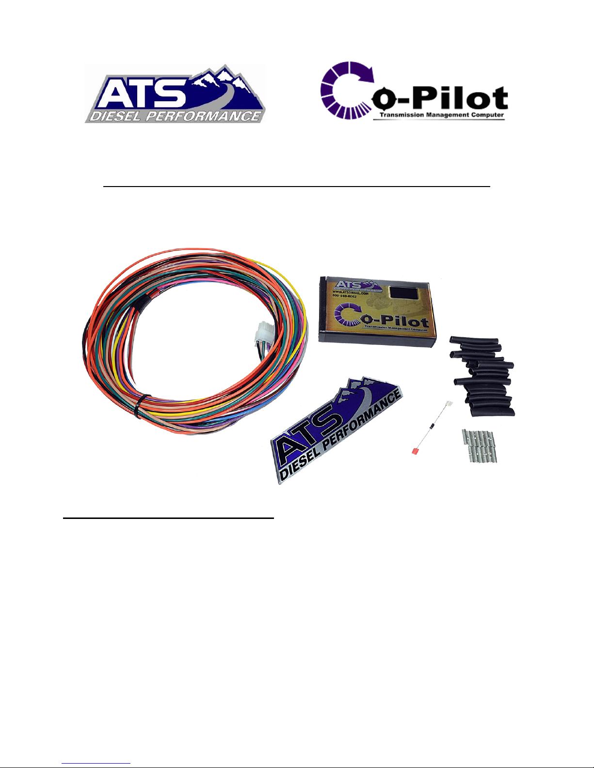
Installation Manual for 2003 Dodge Cummins
Version 3.1
Please read all instructions before the installation of the ATS Co-Pilot Module
Thank you for purchasing the ATS Co-Pilot Module Torque converter/exhaust brake controller.
This manual is to assist you with your installation and operation of the unit. If you are installing the
unit for a customer, please pass this manual on to your customer for future reference.
Understanding the ATS Five Star Co-Pilot
The ATS Co-Pilot transmission controller is recommended for use with light duty pickup trucks
when a heavy-duty aftermarket transmission and torque converter package have been installed on
vehicle. While the Co-Pilot will still function perfectly on a stock transmission, factory transmission
shafts are weak and prone to breakage. The factory torque converter clutch will also fail if applied
under high load conditions. Factory computers are programmed to disengage lockup under certain
conditions which will protect the transmissions internal components under higher load. This is why
we recommend having a heavy-duty aftermarket transmission installed in your vehicle to prevent
transmission failure. ATS Diesel Performance sells many parts for all levels of trucks that will
strengthen your transmission and improve reliability, whether you have a stock daily driver or a
fully built race truck! Give us a call today if you feel the need to get a fully rebuilt transmission for
your truck, or if you just want to strengthen your current transmission with a few upgraded parts.
Our experts can help answer any questions you have and guide you in the right direction.
Page 2
10-03-12 ATS Diesel Performance 601-900-2272-INST
Co-Pilot Adjustment
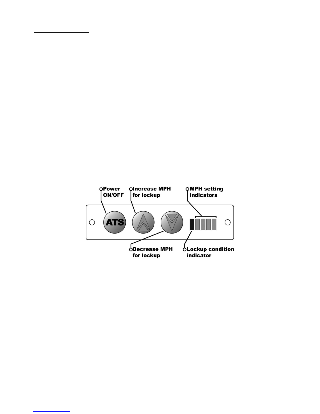
The control panel on the face of the ATS Co-Pilot allows the driver to adjust the lockup of the
transmission. Keep in mind that the Co-Pilot will only lock the torque converter when enough
boost is reached. This keeps the engine from bogging down due to excessively early converter
clutch lockup that is commanded by many factory Transmission control modules. The adjustments
allow you to trim the converter clutch lockup based on MPH. To raise the vehicle speed at which
the transmission locks up, you press the up arrow button. To decrease lockup speed, press the down
arrow button. When the torque converter is locked, the Co-Pilot will display a green light to
indicating that the converter has locked up. Due to the protection the Co-Pilot provides and the
engine load sensing of the Co-Pilot, it is not possible to command Lock-up at too-low engine speeds
or low torque levels. This unique feature ensures the engine will never bog or run at a low engine
RPM, thusly causing lugging when the engine does not have boost. At the other end of the
spectrum, during high power output when the engine is running at full load, the Co-Pilot will keep
the torque converter clutch engaged, allowing full torque to be transferred through the torque
converter clutch to the transmission input shaft. The factory often disengages the torque converter
clutch during these high torque conditions to reduce the load exerted on the factory transmission
shafts. This is the primary reason we do not recommend installing a Co-Pilot transmission controller
on a stock torque converter or transmission.
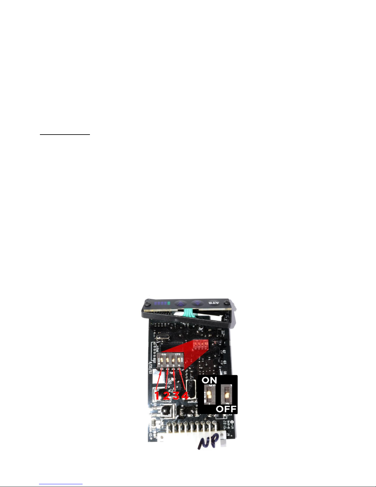
The ATS Co-Pilot will need to be set up for your vehicle and application. The Co-Pilot will need to
be disassembled to access the dip switches on the electronic board. You will need a 1/16
hex (Allen wrench) to remove the face from the Co-Pilot. After the face has been removed the
electronic board can be slid out of the casing from the front. The digital face is attached to the
circuit board with a ribbon cable; do not force the board from the case. There are four (4) switches
on the circuit board; the switches allow the user to select the features desired. The settings are listed
below. When reinstalling the face on the Co-Pilot do not over tighten the 2 small screws on the face
or faceplate failure will result.
th
- inch
Page 3
10-03-12 ATS Diesel Performance 601-900-2272-INST
Dip switch selection:
---------------------------------------------------------------------------------------------------------------------------------------
Switch #1
If your Dodge’s transmission has a stock valve body flip #1 switch to ON position
If your Dodge’s transmission has an ATS valve body flip #1 switch to OFF position
----------------------------------------------------------------------------------------------------------------------------- ----------
Switch #2
Automatically cancels OD from a stop, only cancels after ignition has cycled, cancels at speed
above 3mph.
IMPORTANT: If the white wire of the Co-Pilot harness is not connected, then switch #2 must
be set to the “ON” position. With the wire connected the options below are available.
If you want automatic OD cancel from a stop flip #2 switch ON
If you do not want automatic OD cancel from a stop flip #2 switch OFF
----------------------------------------------------------------------------------------------------------------------------- -----------
Switch #3
Speed setting
On=low speed cut out (deceleration only) This setting is designed to be used with an exhaust brake.
Off=Hi speed cut out (deceleration only)
----------------------------------------------------------------------------------------------------------------------------------------
Switch #4
Set this switch to the ON position
---------------------------------------------------------------------------------------------------------------------------------------
We have preset the Co-Pilot module #1-ON, #2-ON, #3-OFF, #4-ON
Page 4
10-03-12 ATS Diesel Performance 601-900-2272-INST
Co-Pilot Module Mounting Location
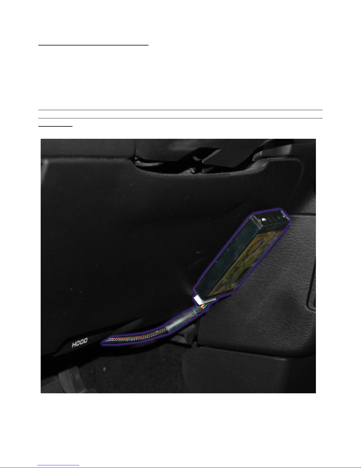
Find a convenient location to mount the Co-Pilot module with in reach and view of the driver. The
Co-Pilot interface must be within visual range of the driver as well as in easy reach. We have found
the ideal place to locate the module is just to the right of the driver on the lower dash panel just
above the right knee. Use the Velcro supplied to secure it to the dash. Before sticking the Velcro to
the dash use brake clean or acetone on the area the sticker will be. Run the Co-Pilot wires that are
to be wired up to the PCM (Power-train control module) and the transmission through the firewall.
Between 2003 and 2004 Dodge moved the PCM from the Passenger side firewall to the Driver side
engine block. Follow the instructions for your application. This kit is for Dodges with the PCM on
the firewall.
Page 5
10-03-12 ATS Diesel Performance 601-900-2272-INST
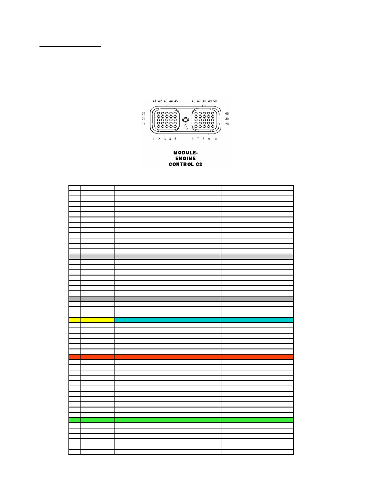
CAV Circuit Function Co-Pilot Connection
1- - 2- - 3K615 18VT/WT INLET AIR TEMPERATURE SENSOR 4- - 5K176 18BR/OR INTAKE AIR HEATER NO.2 RELAY CONTROL 6K174 18BR/YL INTAKE AIR HEATER NO.1 RELAY CONTROL 7K31 18BR FUEL PUMP RELAY CONTROL 8- - -
9T41 18YL/DB PARK/NEUTRAL POSITION SWITCH (T41) 10K161 18BR/LB FAN SPEED SENSOR 11B22 18DG/YL VEHICLE SPEED SIGNAL NO.1 12G6 18 VT/GY OIL PRESSURE SENSOR 13T6 18DG TOW/HAUL OVER DRIVE CANCEL SWITCH Tap White Co-Pilot Wire Pin 5
14T118 18 DG GOVERNER PRESSURE SOLENOID CONTROL 15T9 18DG/TN 3-4 SOLENOID CONTROL 16D21 18WT/BR SCI TRANSMIT(ECM) 17- - 18T38 18YL/BR GOVERNOR PRESSURE SENSOR SIGNAL 19D20 18WT/LG SCI RECIEVE(ECM) 20A209 16RD FUSED BATTERY(+)
21Z902 16BK GROUND Tap Black Co-pilot Wire Pin 9
22- - 23F856 18YL/PK 5 VOLT SUPPLY
24K900 18DB/DG SENSOR GROUND 25T75 18YL/LB TORQUE CONVERTER CLUTCH SOLENOID Connect Co-Pilot Pin 10 and Pin 11
26N4 18DB/WT FUEL LEVEL SENSOR SIGNAL 27- - 28D25 18WT.VT PCI BUS 29T54 18DG/OR TRANSMISSION TEMERATURE SENSOR SIGNAL 30A209 16RD FUSED BATTERY(+) 31T55 18YL/DB TRANSMISSION CONTROL RELAY CONTROL 32F202 18PK/GY FUESED IGNITION SWITCH OUTPUT(RUN-START) Tap RED Co-Pilot Wire Pin 1
33K854 5 VOLT SUPPLY 34- - 35K616 18BR/YL INLET AIR PRESSURE SENSE 36V32 18VT/YL BRAKE SWITCH NO.2 SIGNAL 37B29 18DG/WT BRAKE SWITCH NO.1 SIGNAL 38- - 39- - 40A209 16RD FUSED BATTERY(+) 41C13 18LB/OR A/C CLUTCH RELAY CONTROL 42- - 43K160 18BR/OR FAN CLUTCH CONTROL 44T14 18DG/BR OUTPUT SPEED SENSOR Tap Green Co-Pilot Pin 17
45T13 18DG/VT SPEED SENSOR GROUND 46V37 18VT S/C SWITCH NO.1 SIGNAL 47K25 18DB/VT BATTERY TEMP SIGNAL 48K400 18VR/VT APPS NO.2 RETURN 49Z902 16BK GROUND 50Z902 16BK GROUND -
Wiring the Co-Pilot
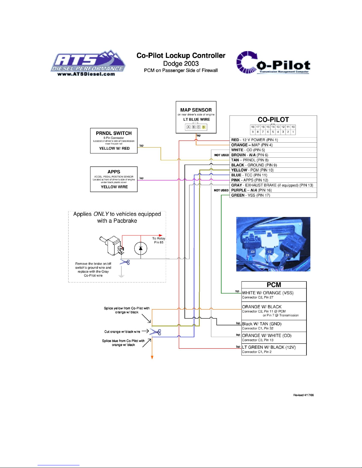
The Co-Pilot has several connections that need to be made in order for it to function properly. There
are several wires which are optional but still included to give the Co-Pilot a more versatile use
depending on your trucks current setup. Use the diagram below as a reference when installing your
Co-Pilot to avoid any conflicts or confusion.
C2 Connector
Page 6
10-03-12 ATS Diesel Performance 601-900-2272-INST
-Red Wire- +12V Power – PIN #1
Reasons for use: The red wire supply’s key on power to the Co-Pilot so it can turn on and be
functional. NOT OPTIONAL
Locate a Power wire at the vehicles PCM. Tap the Pink/Gray wire that goes to Pin 32 of the C2
PCM Connector (PCM is located on the Passenger side firewall). This is the run/start signal.
-Black Wire- Ground (GND) – PIN #9
Reasons for use: The black wire is a constant ground which allows the Co-Pilot to turn on and be
functional. NOT OPTIONAL
Locate a Power wire at the vehicles PCM. Tap the Black wire that goes to Pin 21 of the C2 PCM
Connector (PCM is located on the Passenger side firewall).
-Orange Wire- MAP – PIN #4 (* OPTIONAL*)
Reasons for use: This function allows the Co-Pilot to sense engine load to better enhance its ability
to control the TCC application.
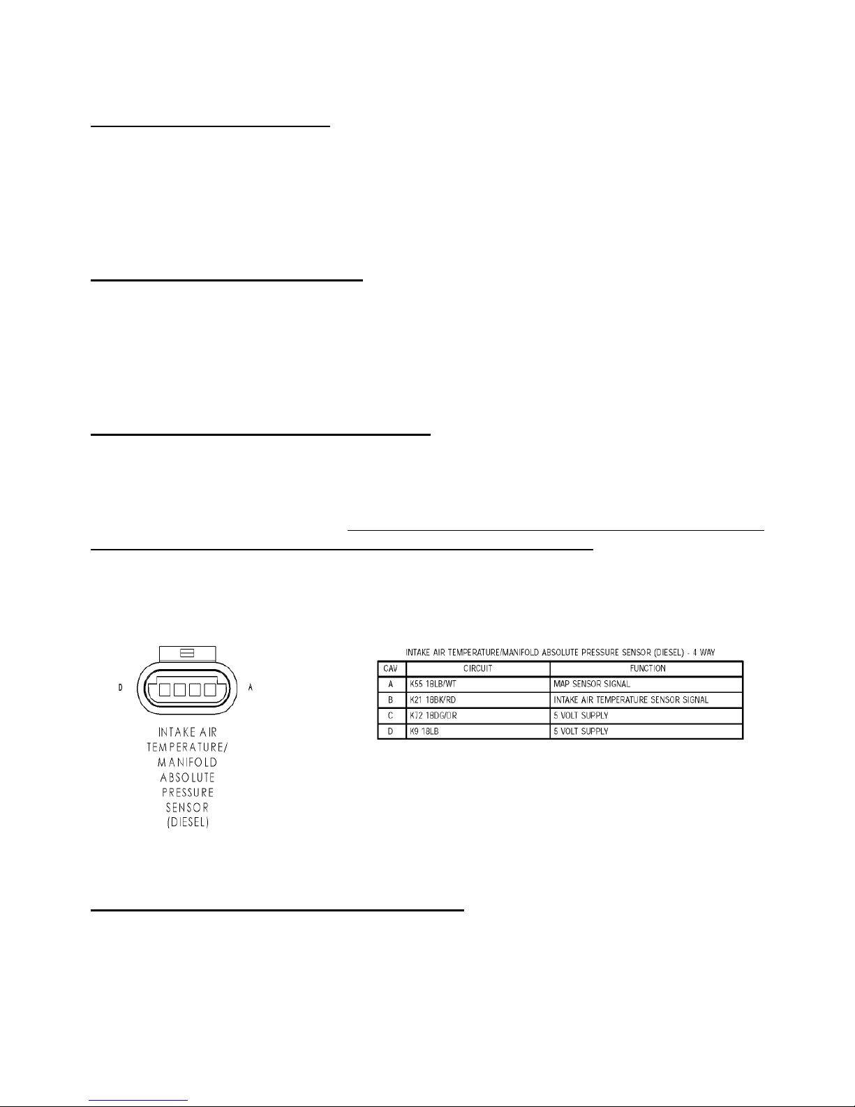
Locate the MAP sensor signal wire. If the vehicle has any aftermarket modifications that also tap
this MAP wire, make sure that the Co-Pilot’s tap is closest to the sensor. Tap the Lt. Blue/White
Cavity A, wire that goes to the MAP sensor. MAP sensor is located on rear driver’s side of engine.
-White Wire- Overdrive – PIN #5 (* OPTIONAL *)
Reason For use: This wire gives the Co-Pilot the ability to automatically cancel overdrive.
Tap the Dark Green wire that goes to Pin 13 of the C2 PCM Connector.
Page 7
10-03-12 ATS Diesel Performance 601-900-2272-INST
-Yellow Wire– PCM - PIN #10 and -Blue Wire– TCC - PIN #11
Locate the vehicle’s Torque Converter Clutch (TCC) wire coming from the vehicle’s PCM to the
transmission. Cut the Yellow/Light Blue wire that goes to Pin 25 of the C2 Connector. Be sure to
leave at least 2 inches of wire coming from the plug. Reference the wiring diagram before
cutting. Protect the connections.
Connect the Yellow wire coming from the Co-Pilot to the wire that goes to the PCM. Connect the
Blue wire coming from the Co-Pilot to the wire that goes into the wire loom to the transmission.
If at anytime you would like to bypass the Co-Pilot’s operation, simply unplug the wiring
harness from the Co-Pilot Module and jumper the harness’ blue and yellow terminals
together with a paperclip. See the Troubleshooting section for more detail.
-Pink Wire- Accelerator Pedal Position Sensor (APPS) – PIN #12(* OPTIONAL *)
Reason For use: This wire give the Co-Pilot the ability to lock the torque converter on
deceleration. This gives the vehicle an engine-braking effect. Recommended. OPTIONAL:
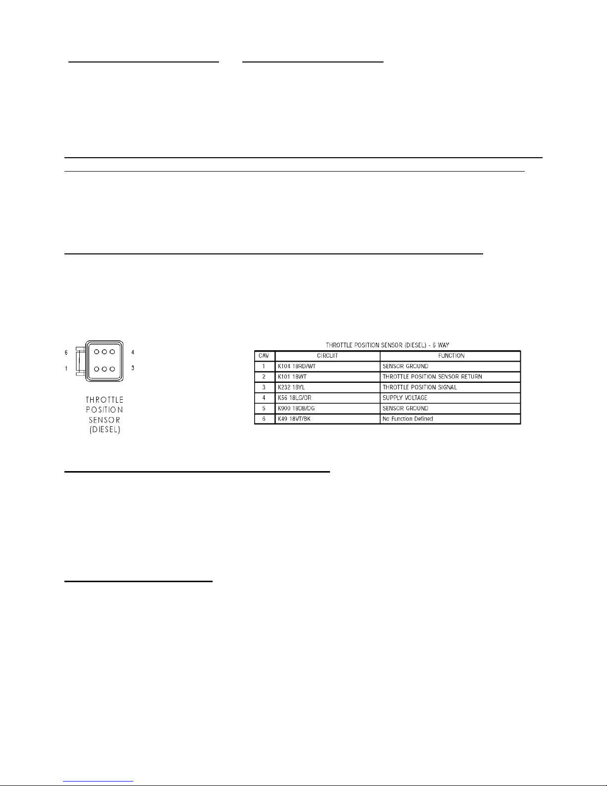
Locate the APPS, it is under a black plastic cover, on the driver’s side of the engine, in front of the
intake manifold. Tap the Yellow wire in the APPS Plug wire loom Cavity 3.
-Green Wire- Vehicle Speed Sensor (VSS) – PIN #17
Reasons for use: This is how the Co-Pilot is able to know what speed of the vehicle is traveling so
it can control the TCC Lock up speed. NOT OPTIONAL
Locate the VSS (Vehicle Speed Sensor) wire in the vehicle’s computer wiring harness. Tap the
Dark Green/Brown wire that goes to Pin 44 of the C2 Connector.
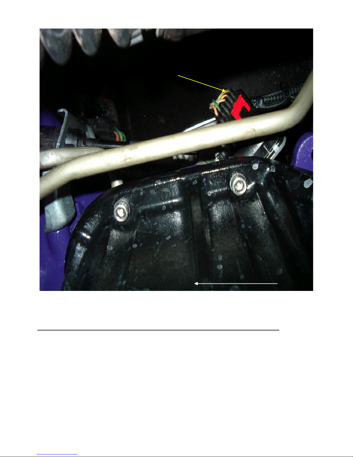
-Tan Wire- PRNDL – PIN #8
Reasons for use: This allows lock up when manually downshifting into 2nd gear.
Locate the PRNDL Switch/Transmission Range Selector (6-Pin Connector) that is located on the
driver’s side of the transmission, near the pan rail. Tap the Yellow w/ Red wire.
Page 8
10-03-12 ATS Diesel Performance 601-900-2272-INST
To front of vehicle
PRNDL Switch
-Brown Wire (Pin #6) and Purple Wire (Pin #16) is NOT USED in this installation
View from bottom for 48RE Transmission
Page 9

10-03-12 ATS Diesel Performance 601-900-2272-INST
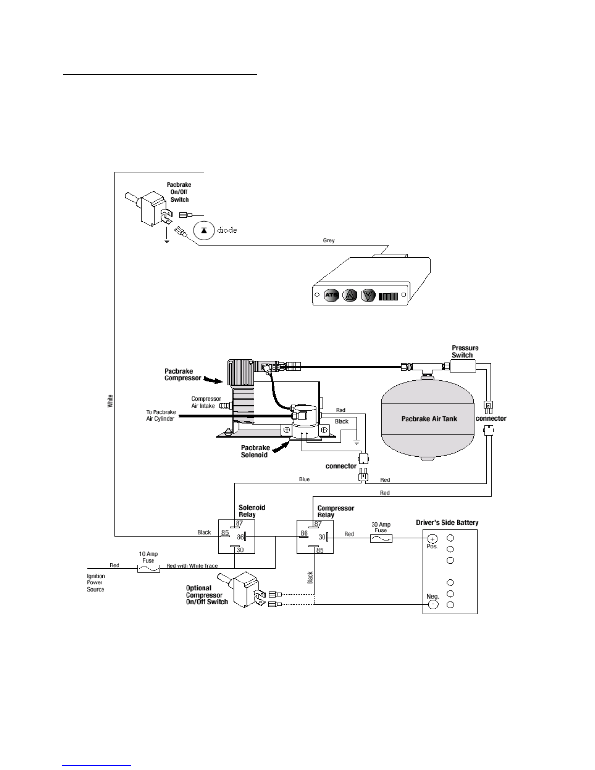
-Gray Wire- Exhaust Brake – PIN #13
If you do not have an exhaust brake, skip this section.
Reason for use: This function allows your aftermarket or factory exhaust brake to turn on with the
Co-Pilot torque converters lockup when decelerating only. OPTIONAL
If you do not have an exhaust brake, leave the Grey wire unconnected.
Locate the exhaust brake solenoid. There should be 2 wires coming off of the solenoid. One wire
delivers power to the solenoid via a power switch mounted inside the cab. The other wire supplies
ground to the solenoid. The ground wire that comes from the solenoid to the ground on the engine
must be removed and connected to the gray wire that comes from the Co-Pilot module. The
Exhaust-brake feature of the Co-Pilot will only work with an exhaust brake that uses a solenoid to
actuate it. We recommend the use of a Pacbrake with our Co-Pilot. Some exhaust brakes do not
use a solenoid, instead they use a computer module. In this case you will need to add a relay in the
circuit to control the exhaust brake or use the Co-Pilot as a stand-alone unit. We have supplied
wiring diagrams that detail the connection to a Pacbrake.
You can use the warm-up feature of your exhaust brake by simply turning off the Co-Pilot
Box and turning on the exhaust brake’s toggle switch.
Please note: If you are installing a Pacbrake now, or in the future, you do not need to make
any Pacbrake connections at the ECM or install the Pacbrake ECM Bypass Kit.
Page 10
10-03-12 ATS Diesel Performance 601-900-2272-INST
-Diode- All models with Exhaust Brake
There is a stripe on the diode that indicates the positive side. Attach the positive side of the diode to
pin 85 of the Pacbrake relay. Attach the negative side of the diode to the gray Co-Pilot wire. See
the provided wiring diagram for clarification.
Recommended exhaust brake wiring
Page 11

10-03-12 ATS Diesel Performance 601-900-2272-INST
Troubleshooting
If you experience problems after installation, there is a simple test to help diagnose the problem.
Simply unplug the wiring harness from the back of the Co-Pilot module and put a bent paperclip
into blue and yellow terminals of the harness’ plug (jumper the blue and yellow together). This
reconnects the wire that you cut at the transmission plug and bypasses the Co-Pilot completely.
If your pickup behaves normally after bypassing the Co-Pilot: Make sure you are following the
operating instructions correctly and that all wire connection are good and to the proper
wires. If the problem continues, contact our Technical Support department at
[email protected] or 800-949-6002.
If the problem continues after bypassing the Co-Pilot: There is a problem with a wire
connection. Double-check all connections. Make sure your solder connections are good, if
any look suspect, re-solder. Make absolutely sure that all taps were made on the correct
wires. Some of these wires can be easily confused with neighboring ones especially if the
connection was made away from the plug, inside the wiring harness. If the problem
continues, contact our Technical Support department at [email protected] or 800-949-
6002.
Have Any Questions?
Thank you for purchasing the ATS Co-Pilot. Please check our website at http://www.atsdiesel.com
for technical support and other performance products such as the 5-Star™ torque converter, ATS
Valve Body and ATS Transmission along with our full line of products please call or e-mail our
Technical Service Department, 8:00am to 5:30pm Mountain Standard Time, Monday through
Friday.
Contact Information
Toll Free: 800-949-6002
Local: 303-431-7973
Fax: 303-431-0135
Website: www.ATSDiesel.com
We strive to make our instructions as clear and complete as possible. To achieve this, our
instructions are under constant construction. We encourage you to visit our website for the
most up-to-date manuals and diagrams as well as other information. If you have any
suggestions as to how we can improve this installation manual, let us know at
Page 12
10-03-12 ATS Diesel Performance 601-900-2272-INST
 Loading...