

Page 1
www.altronics.com.au
User manual revision number: 1.5 29/08/16
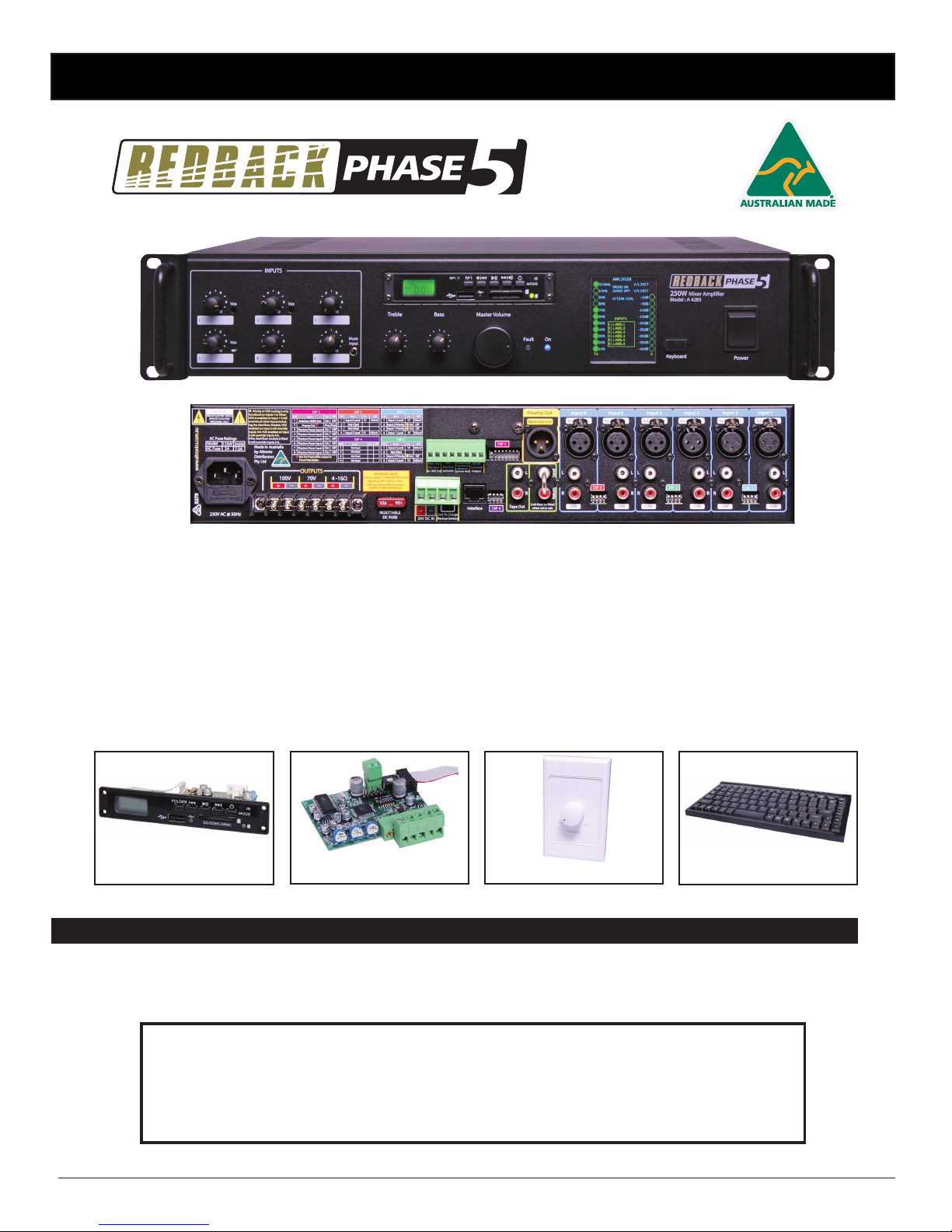
Operating Manual
A 4275 125W Mixer Amplier
A 4285 250W Mixer Amplier
Redback® Proudly Made In Australia
Distributed by Altronic Distributors Pty. Ltd.
Phone: 1300 780 999 Fax: 1300 790 999 Internet: www.altronics.com.au
IMPORTANT NOTE:
Please read these instructions carefully from front to back prior to installation.
They include important setup instructions.
Failure to follow these instructions may prevent the amplier from working as designed.
Optional Extras
A 2280B Remote VolumeA 2711 MP3 Module A 4573 Alert/Evac Board D 2111 Keyboard USB/PS2
Page 2

www.altronics.com.auRedback® Proudly Made In Australia
2
REDBACK is a registered trademark of Altronic Distributors Pty Ltd
Since 1976 Redback ampliers have been manufactured in Perth, Western Australia by Altronics. With over 35 years
experience in the commercial audio industry, we offer consultants, installers and end users reliable products of high build
quality with local product support. We believe there is signicant added value for customers when purchasing an
Australian made Redback amplier or PA product
Australian Made Status
All Redback house products made by Altronics will now be sporting the ofcial Australian Made logo. Since starting
manufacturing of commercial audio equipment in the mid 70’s we have always taken pride in producing a quality local
product.
The new adoption of the Australian Made logo will help us get the word out to local and export markets that our
products carry the ofcial compliance seal of the Australian Made campaign. We have always pushed our ‘local is better’
line in all of our marketing efforts, it’s always an added boost when you are backed up by a widely recognised and
respected icon.
Industry leading 10 year warranty.
There’s a reason we have the industry leading DECADE warranty. It’s because of a long tried and tested history of bulletproof reliability. We’ve heard PA contractors tell us they still see the original Redford amplier still in service in schools that’s over 37 years of operation - and still going strong!
Published by Altronic Distributors
© 2014 Altronic Distributors
Page 3

www.altronics.com.au Redback® Proudly Made In Australia
3
1.0 Overview
1.1 Introduction 4
1.2 Features 4
1.3 What’s in the box 4
1.4 Front panel guide 5
1.5 Rear panel connections 6
1.6 Led Status Indicators 9
1.7 Protect Mode 9
1.8 LCD Status Indicators 9
1.9 LCD Overview 10
1.10 Label the input sources, service information and setting up min and max volumes 11
2.0 Setup
2.1 Setup Guide 12
2.2 Priorities 13
2.3 DIP Switch Settings 14
2.4 Adjusting VOX levels 15
2.5 Installing the A 4573 Alert/Evac Module 16
2.6 PTT and 24V DC Switched Out 17
2.7 Remote Volume Control 18
2.8 Preamp Out, Tape Out, Send and Return 19
2.9 Backup battery charging 19
2.10 Fitting the optional A 2711 MP3 module 20
3.0 Troubleshooting 22
4.0 Specications 23
Contents
Page 4

www.altronics.com.auRedback® Proudly Made In Australia
4
Overview
1.0 OVERVIEW
1.1 INTRODUCTION
The REDBACK range of mixer ampliers are engineered to a very high standard and are packed with a host of features to
satisfy a large range of installations.
1.2 FEATURES
• Very low noise and distortion
• Thermal overload protection
• Thermally cued forced fan cooling
• Protect Mode
• 4 levels of priority/Vox muting
• LCD display of amplier status
• Minimum and Maximum Master Volume Over-ride
• Minimum and Maximum Remote Volume Over-ride
• USB keyboard interface for labelling of inputs and installer contact details.
• 6 inputs congurable as balanced microphone or line
• Music Input on front panel
• Adjustable line level sensitivity
• 70V, 100V and 4-16ohm outputs
• 240V AC or 24V DC operation
• 300mA Backup Battery charging
• Phantom power (on microphone inputs)
• Tape out (Dual RCA)
• Pre-amp send and return connections (RCA)
• Balanced line output (3 pin male XLR)
• Remote Volume option
• 24V switched output via PTT microphone (not supplied)
• 19” Rack Mount (2 unit).
• Optional Alert/Evac tones with voice-over message (via A 4573 module)
• Optional MP3 input with remote control (via A 2711 module)
1.3 WHAT’S IN THE BOX
A 4275/85 Mixer Amplier
240V AC IEC C13 Appliance Mains Lead 10A 3 Pin Black
Instruction Booklet
Page 5
www.altronics.com.au Redback® Proudly Made In Australia
5
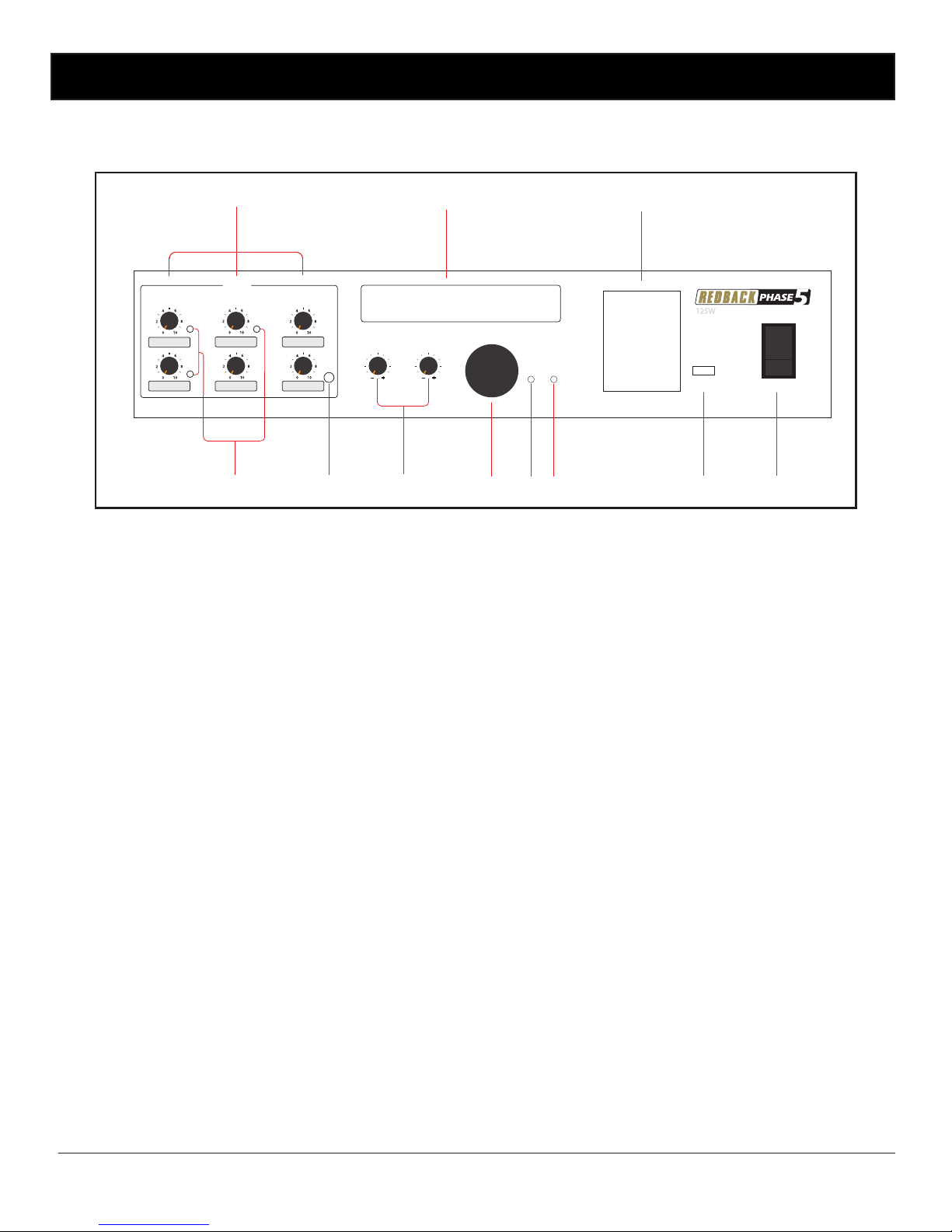
Fig 1.4 shows the layout of the front panel.
Fig 1.4
1 Inputs 1-6 volume controls
Use these controls to adjust the output volume of inputs 1-6.
2 Optional Music Input Module
Remove this cover to install optional music input module. This module over-rides the rear input 6 and is
adjusted via the volume 6 pot.
3 LCD
Displays amplier status, input and output levels, heatsink temperature, faults, voltage input and input labels.
4 Power Switch
Use this to turn the unit on.
5 USB - PS2 compatible keyboard input.
Use a standard PS2-USB keyboard (such as Altronics D 2111) to label inputs, installer information and to
access some additional features. (see section 1.10 for more details)
6 On Indicator
This led indicates the unit has power.
7 Fault Indicator
This led indicates when the amplier has a fault.
8 Master Volume
Use this control to adjust the master volume. This is a mutli-turn adjustable control.
9 Bass and Treble Controls
Use these controls to adjust the bass and treble.
10 Music Input
Use this input to connect a portable music player. This input over-rides the rear input 6 and the optional
Music input module (if tted) and is adjusted via the volume 6 pot.
11 Vox level controls
Use these controls to adjust the vox sensitivities of inputs 1-3.
1.4 FRONT PANEL GUIDE
Overview
1
9
8
2
736
5 4
1011
0
2
4
6
8
10
0
2
4
6
8
10
0
2
4
6
8
10
0
2
4
6
8
10
0
2
4
6
8
10
0
2
4
6
8
10
_
+
_
+
Power
Fault
INPUTS
Model : A 4275
125W Mixer Amplier
TrebleBass
Master Volume
On
1
2
3
4
5
6
Vox
Vox
Music
Input
Keyboard
Vox
Page 6

www.altronics.com.auRedback® Proudly Made In Australia
6
1.5 REAR PANEL CONNECTIONS
Fig 1.5 shows the layout of the rear panel.
Fig 1.5
1 Switched 24V 1A output, PTT (Push to talk) muting, Remote Volume and Power fail Contacts
Switched 24V 1A output
When set to “On” via the output DIP switch (see DIP switch settings section 2.3 ) 24V DC appears at the “24V DC
Switched Out” terminals on the rear panel, whilst the PTT terminals are shorted together, or whenever any
priority/Vox is activated. The switched 24V output could be used to control external devices like remote volume
controls with bypass relays for emergency paging.
PTT Muting Contacts
These contacts are shorted together to activate. The The PTT (Push to talk) is normally done with the switch of a
push to talk microphone.
Remote Volume
Overall volume can be adjusted by a remotely located volume control. This requires a two wire gure 8 type cable
and a 1kohmΩ potentiometer connected as shown in section 2.6. Maximum distance 100m.
` Power Fail Contacts
These contacts close when the power to the amplier is removed. This could be used to activate a buzzer or
remote warning light to indicate power failure to the amplier.
DIP 2
SW Item On O
12Input 4 Level 1V 100mV
3
Not USed
4 Input 3 Level 1V 100mV
Input 3 Priority On O
*
DIP 1
SW Item On O
12Input 2 Level 1V 100mV
3
Input 2 Priority On O
4 Input 1 Level 1V 100mV
Input 1 Priority On O
*
*
4 -16Ω70V
230V AC @ 50Hz
100V
OUTPUTS
L
R
24V DC IN
Balanced Mic
+
_
PTT
(short to
activate)
Power Fail
(Contacts
close on
power fail)
SendReturn
Tape Out
Preamp Out
Link To Charge
Backup battery
Input 1Input 3 Input 2Input 4Input 5Input 6
ALERT - EVAC MODULE
Output Levels
Voice Chime Alert
Over & Evac
EV COMCANCH
AL
Triggers
L
R
+
–
Rem. Vol
Connect
to 1KΩ Pot
+–+–+
–
Line
24V DC
Switched
Output
DIP 5
Interface
DIP 4
DIP 1
DIP 2DIP 3
Balanced Mic
Line
Balanced Mic
Line
Balanced Mic
Line
Balanced Mic
Line
Balanced Mic
Line
Balanced Line
L
R
L
R
L
R
L
R
L
R
2
6
7
3 4 5
161718
1
15
14
13
12
10 911
8
www.altronics.com.au
RISK OF ELECTRIC SHOCK
OPEN BY QUALIFIED
PERSONNEL ONLY
!
CAUTION
Made in Australia
by Altronic
Distributors
Pty Ltd
DIP 3
SW Item On O
12Input 6 Level 1V 100mV
3
Not USed
4 Input 5 Level 1V 100mV
Not USed
SW
Item On
O
1
2
3
4
Not Used
Not Used
Not Used
Not Used
DIP 4
SW
Item On O
Switched 24VDC Out On O
Phantom Power Input 6 On O
On O
1
2
3
4
Phantom Power Input 5
On O
5
Phantom Power Input 4
On O
6
Phantom Power Input 3
On O
7
Phantom Power Input 2
On O
8
Phantom Power Input 1
Preamp Out
†
Post
Pre
†
Sets the Preamplier output to
Pre or Post Master.
DIP 5
Priority or VOX muting is only
functional on inputs 1-3. When
VOX is enabled on input 1 it will
override all other inputs including the Alert/Evac Module. VOX
enabled on input 2 will override
inputs 3-6. VOX enabled on input
3 will override inputs 4-6.
If the Alert/Evac module is tted
it will override inputs 2-6.
*
Model
125W
5AAC Fuse
250W
7.5A
AC Fuse Ratings
RESETTABLE
DC FUSE
DIP 5
DIP 4
DIP 1
DIP 2DIP 3
IMPORTANT NOTE
Ensure power is switched OFF when
adjusting DIP switches. New
settings will be eective when
power is switched back on.
2 1
3
2 1
3
2 1
3
2 1
3
2 1
3
2 1
3
2 1
3
1 2 3 4 5 6 7 8
1 2 3 4
1 2 3 4
1 2 3 4
1 2 3 4
Overview
Page 7

www.altronics.com.au Redback® Proudly Made In Australia
7
Overview
The A 4275/85 range of mixer ampliers have provison to plug in an optional Alert/Evacuation module (A 4573). The
controls are listed below (see section 2.5 for more details).
2 Voice Over Volume
Use this trimpot adjustment to change the output level of the playback message.
3 Chime Volume
Use this trimpot adjustment to change the output level of the chime volume.
4 Alert and Evacuation Volume
Use this trimpot adjustment to change the output level of the alert and evacuation tone.
5 Alert, Evacuation, chime and cancel contacts
Use these contacts to trigger the chime tones, the alert tone, the evacuation tone and to cancel any
of the tones once triggered. All tones & cancel function are operated by a closing contact to ground.
This could be triggered via building re indicator board, break glass alarm etc.
6 Preamp Out (Balanced Line Output)
A 3 pin 600ohm 1V balanced XLR output is provided for passing the audio signal on to other slave ampliers
or to record the output of the amplier. This output can be set up to be effected (post master volume) by the
master volume control or unaffected (pre master volume). Factory default setting disables the preout. (Refer to
section 2.3 DIP switch settings).
7 Input connectors
There are 6 sets of inputs which can be either balanced mic or line inputs. The line inputs are dual RCA
connectors which are internally mixed to produce a mono input signal.
8 DIP SW 1-3
Inputs 1-6 include an individual 4 way dip switch enabling adjustable input sensitivity (100mV or 1V) and Priority/
VOX muting for inputs 1-3.
Priority/VOX muting is not available on inputs 4-6.
Note, when the Priority/VOX muting function is selected (inputs 1-3) it will operate with the input set for either
microphone or line operation. (see section 2.3 for DIP Switch settings)
9 Pre - amp send and return
This allows external effects units, ie Graphic EQ’S , companders or signal processors to be connected to the
amplier. When not using this feature the send and return outputs must be linked externally (factory tted). The
amplier will not work without this link. Only when an external effects unit is used can it be removed.
(see section 2.8 for more details)
10 Tape Out
Dual RCA’s provided for recording purposes. This level is post master volume. (see section 2.8 for more details)
11 DIP SW 5
These DIP switches set the 24VDC switched output status, determine the Preamp output as pre master volume
or post master volume and also set the phantom power to the balanced inputs. (see section 2.3 settings)
12 DIP SW 4
Not currently used.
13 RJ45 Interface
This is for future expansion of product.
14 Battery Charging
The amplier is provided with a trickle charge circuit to maintain the batteries in a charged condition. The charge
rate is approximately 300mA. Simply link the terminals marked “link to charge backup battery” on the rear of
the amplier. A at battery will generally take overnight to charge, or even longer depending on the battery
capacity. (see section 2.9 for more details)
Page 8
www.altronics.com.auRedback® Proudly Made In Australia
8
i
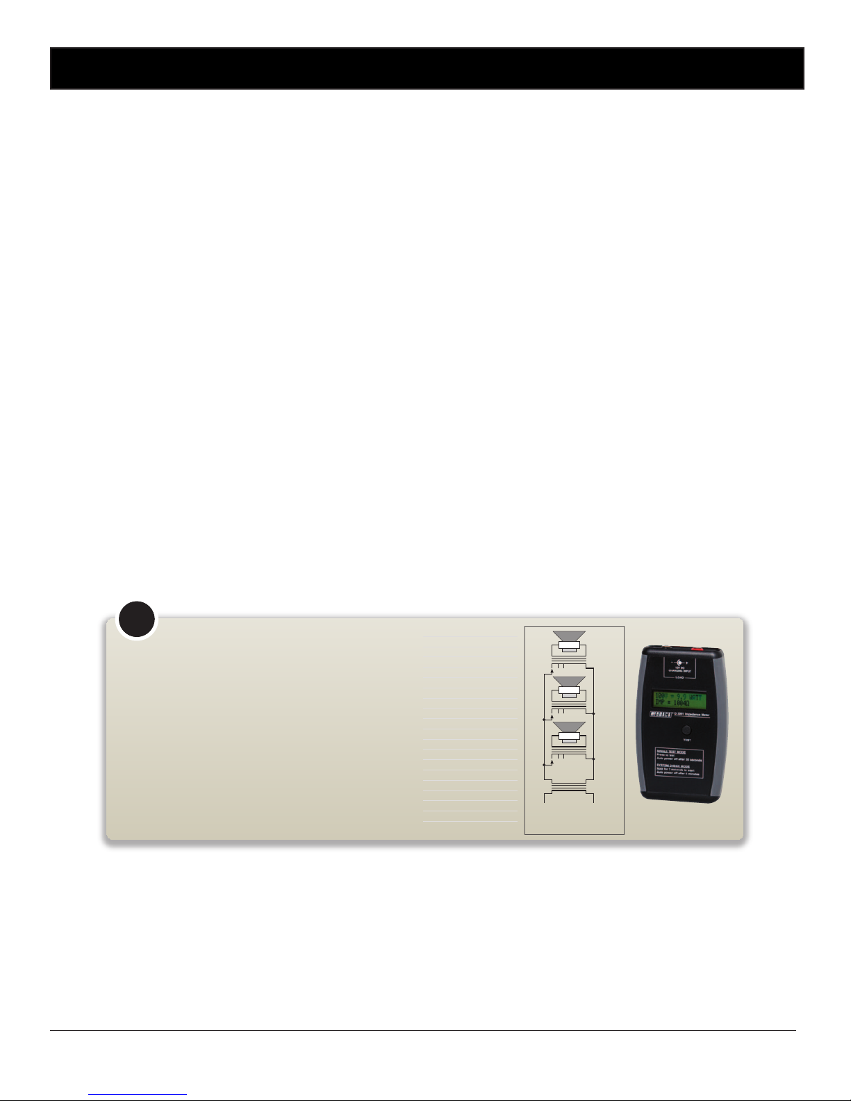
Wiring speakers in parallel for 70/100V line: Where several speakers are to
be used at one time, on one circuit, it becomes necessary to use speakers tted
with line-matching transformers. This is to overcome the effects of connecting
speakers in parallel and cable losses. The amplier generally has an output
voltage of 100 volts (70 volts is typically used in North America, however
operation is similar). In this conguration the total wattage load on the amplier
is derived from adding all the line transformer primary tap ratings together. For
example, 70 one watt speakers will have a total speaker load of 70 watts. Or
alternatively, it is conceivable to connect 100 one watt speakers to a 100 watt,
100 volt line amplier.
Measuring 70/100V Line Speaker Impedance: To measure amplier system
load, you must use an impedance meter in order to measure the ac resistance
of the connected speaker network. Impedance cannot be measured with a
standard multimeter, as this measures the dc resistance. Use the Altronics
Q 2001 or similar impedance meter.
About 70V & 100V Line Speaker Systems
Load 70V 100V
0.5W 9.4kΩ 20kΩ
0.66W 7.12kΩ 15kΩ
1W 4.7kΩ 10kΩ
1.25W 3.76kΩ 8kΩ
2W 2.35kΩ 5kΩ
2.5W 1.88kΩ 4kΩ
3W 1.56kΩ 3.3kΩ
5W 940Ω 2kΩ
7.5W 626Ω 1.3kΩ
10W 470Ω 1kΩ
15W 313Ω 666Ω
20W 235Ω 500Ω
30W 156Ω 333Ω
40W 117Ω 250Ω
60W 78Ω 166Ω
100W 47Ω 100Ω
125W 37Ω 80Ω
250W 19Ω 40Ω
500W 9.4Ω 20Ω
15 24VDC IN
Battery Backup: Provision has been provided to run the amplier from a suitably rated 24V battery system in the
event of a mains failure. Using appropriately rated cable, connect the battery to the “24V DC In” terminals.
Observe correct polarity when connecting. (see section 2.9 for more details)
16 DC Resettable fuse
This fuse protects the internal power supply. If the fuse is tripped it is easily reset by pressing the small button on
the fuse.
17 Output Connections
Speakers with total impedance of 4 to 16 ohms, or speakers tted with a 70V/100V line transformer may be con
nected. Always ensure that the total load of the speakers does not exceed the rated output of the amplier ie
either 4Ω minimum for the 4-16Ω terminals or 80Ω minimum at 100V for the A 4275 (125W) and 40Ω minimum
at 100V for the A 4285 (250W). Otherwise either the DC or mains fuse could blow or the fault led activate and
the amp will shut down. (See the table below.) Always be careful to avoid short circuits and connection to the
wrong terminals.
18 240V AC power socket (Australian standard)
Connects to 240V AC mains power with the included IEC lead.
Altronics Q 2001
Impedance Meter
Overview
Page 9

www.altronics.com.au Redback® Proudly Made In Australia
9
1.6 LED STATUS INDICATORS
There are two led’s on the front panel which indicate when power is available and if there is a fault.
The fault led will turn on under the following conditions.
Overtemp
When the amplier reaches a dangerous temperature the unit will shutdown, preventing damage. If this occurs, check for
short circuits on the speaker line or objects blocking the ampliers air vents.
1.7 PROTECT MODE
If the amplier reaches a critical temperature or is over-driven it will shutdown.
The amplier has been designed with an in built protection mode which will throttle the amplifer back to 50% output if it
nears the shutdown temperature.
If the Protect Mode is active the amplier LCD will ash “ON” and “OFF” to highlight that there is a problem with the
amplier. The fault condition will be displayed on the screen. (see section 1.?? for more details)
1.8 LCD STATUS INDICATORS
The LCD is used to offer more detailed information about the status of the amplier.
The following elements can all be indicated on the display but may not be visible unless required.
• Signal presence
• Master Volume Level
• Amplier Output level in dB
• Remote volume level
• Current Limit Condition
• Voltage Limit Condition
• Heatsink Temperature
• 230V AC Presence
• 24V DC Presence
• Alert/Evac Activation
Overview
Page 10
www.altronics.com.auRedback® Proudly Made In Australia
10
Overview
1.9 LCD OVERVIEW
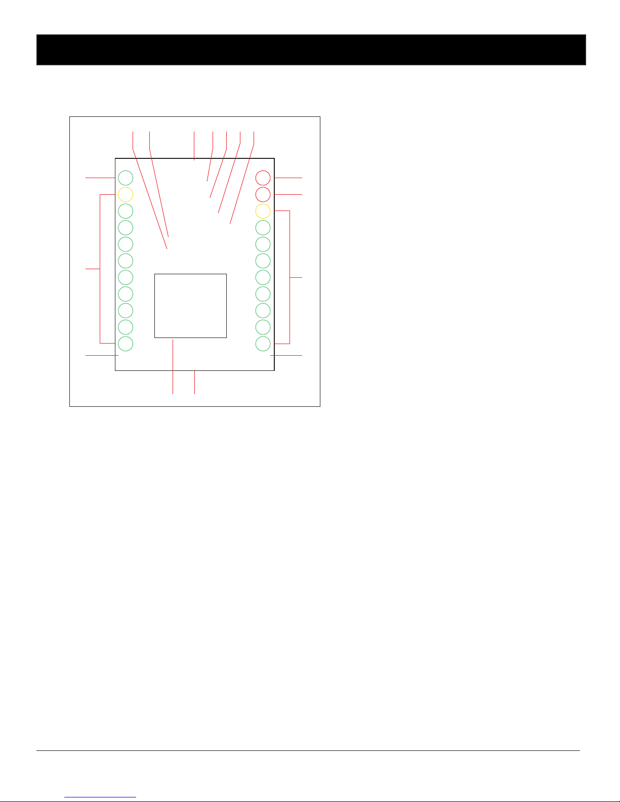
Fig 1.9 shows the layout of the LCD.
1 Zone Label
The Amplier can be given a specic name so it is
easily distinguishable. (Eg Sports Bar,Level 5 etc)
(see section 1.10 for more details).
2 Mains Status Indicator
Indicates when the unit has mains power.
3 24V DC Status Indicator
Indicates when the unit has a 24V DC
backup supply connected.
4 Heatsink Temperature Indicator
Displays the temperature of the internal heatsink.
5 Protect Mode
If the amplier reaches a critical temperature the
amplier will go into protection mode.
6 Current Limit Indicator
If the amplier goes into an over current status this
indicator will come on.
(see section 1.6 for more details)
Fig 1.9
10%
-40dB
ZONE LABEL
SIGNAL
C/LIMIT
MAINS ON
24VDC ON
V/LIMIT
-35dB
-30dB
-25dB
-20dB
-15dB
-10dB
-5dB
0dB
20%
30%
40%
50%
60%
70%
80%
90%
100%
32
SERVICING/INSTALLER LABEL
INPUTS
1) INPUT 1
1) INPUT 2
1) INPUT 3
1) INPUT 4
1) INPUT 5
1) INPUT 6
H/SINK TEMP
1 2 3304 5
6
7
8
9
1011
12
13
14
15 16
CURRENT LIMIT
EMERG TONES
PROTECT MODE
7 Voltage Limit Indicator
If the amplier goes into an over voltage status
this indicator will come on.
(see section 1.6 for more details)
8 VU Meter
Displays the output of the amplier in 5dB
increments.
9 VU Level
Displays the actual dB output of the amplier.
10 Servicing/Installer label
The Amplier can be given a label which the
installer can use for servicing details (such as
“For service Call 1300 123 456”)
(see section 1.10 for more details).
11 Input labels
The Amplier has 6 inputs which can all be given
a meaningful label (such as DVD,CD Tuner etc)
(see section 1.10 for more details).
12 Master Volume Level
Displays the actual master volume level.
13 Master Volume Meter
Displays the master volume level in 10%
increments.
14 Signal Presence Indicator
Indicates when the amplier has an input signal.
15 Emergency Tones Indicator
Indicates when the optional A 4573 Alert/Evac
Module is active.
16 Current Limit Indicator
Indicates when the amplier is drawing its
maximum current.
Page 11

www.altronics.com.au Redback® Proudly Made In Australia
11
1.10 Label the Input Sources, Service Information and setting up Min and Max Volumes
A number of options in the A 4275/85 amplier can be congured through the LCD by connecting a keyboard.
• Label Input Sources
• Label the Zone
• Label Servicing (or Installer) information
• Set Minimum and Maximum Remote Volume Levels
• Set Minimum and Maximum Master Volume Levels
Plug a standard PS2-USB keyboard (such as Altronics D 2111) into the USB socket on the front of the ampler. The
keyboard will be automatically detected and navigate the user to the amplier setup screen.
There are a number of options available.
1) Label the input sources
Press the letter “i” on the keyboard. This will navigate the user to the “label inputs screen”. Press the numbers
1-6 on the keyboard to select the input to label. Audio source examples might include CD Player, Radio, etc. A
maximum of ten characters is available for each label. To use capital letters hold down the shift key when typing.
2) Label the Zone.
Press the letter “z” on the keyboard. This will navigate the user to the “label Installer screen”. Type in the label
required and press return. Press escape to exit back to the main label input screen.
3) Label the Service Information.
Press the letter “s” on the keyboard. This will navigate the user to the “label Zone screen”. Type in the label
required and press return. Press escape to exit back to the main label input screen.
4) Reset all Labels.
Press the letter “r” on the keyboard. This will navigate the user to the “reset all labels screen”. Press enter to con
rm or ESC to exit.
5) Set the Minimum and Maximum Remote Volume Levels.
If the remote volume is used and the volume levels need to be set so that they cannot go beyond certian limits
then this function can be very useful.
Press the letter “v” on the keyboard. This will navigate the user to the “Set Remote Volume Min/Max screen”.
Press the number “1” to set the minimum and “2” to set the maximum. Enter a number between 0 and 100.
Press escape to exit back to the main label input screen.
6) Set the Minimum and Maximum Master Volume Levels.
If the Master volume is required to be set so that the volume cannot go beyond certian limits then the minimum
and maximum volume levels can be set here.
Press the letter “m” on the keyboard. This will navigate the user to the “Set Master Volume Min/Max screen”.
Press the number “1” to set the minimum and “2” to set the maximum. Enter a number between 0 and 100.
Press escape to exit back to the main label input screen.
Overview
Page 12
www.altronics.com.auRedback® Proudly Made In Australia
12
Setup
Fig 2.1A
2.0 SETUP
2.1 Setup Guide
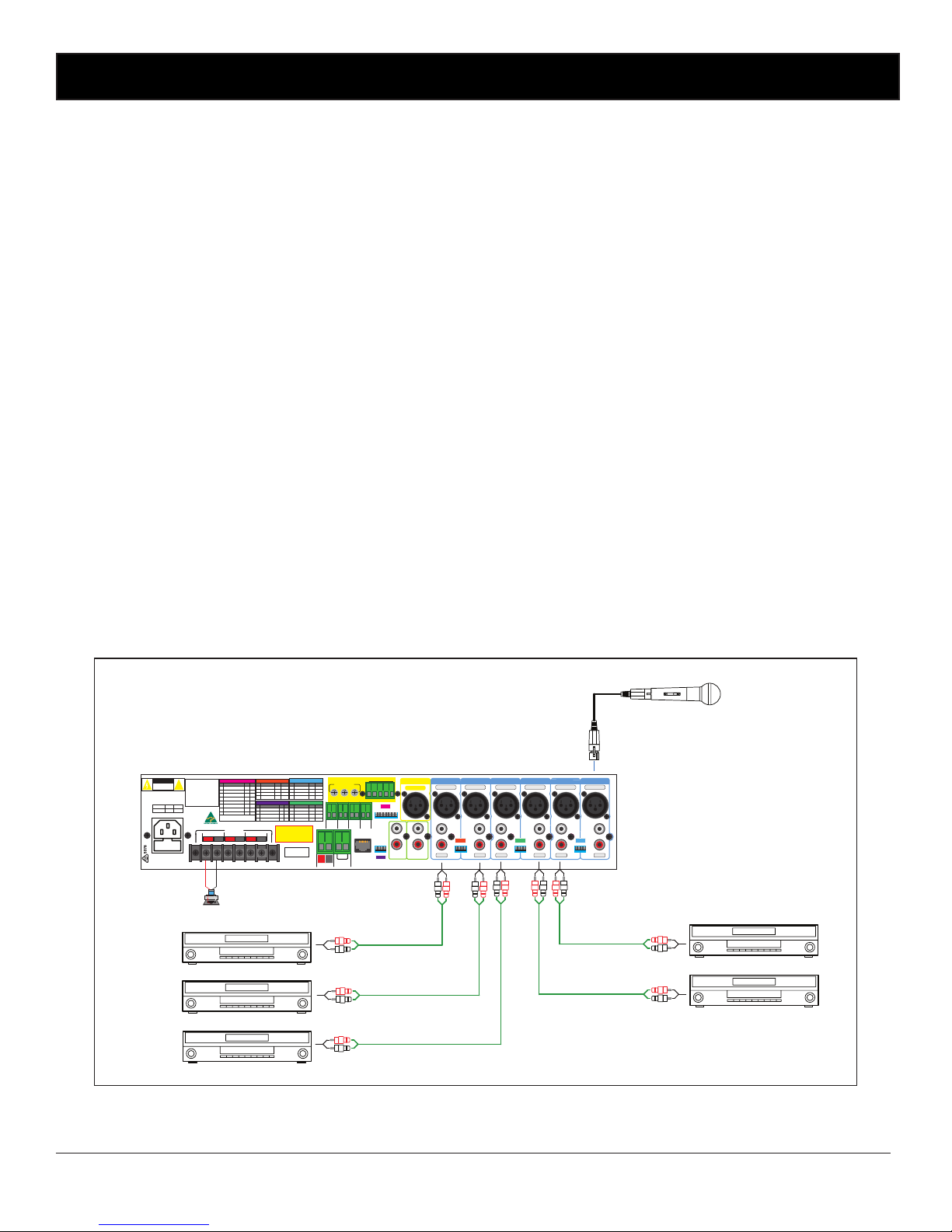
The A 4275 and A 4285 mixer ampliers have a total of six inputs congurable as either Dual RCA (Line input) or 3 Pin
Male XLR (Mic inputs). Each Input includes an individual 4 way dip switch enabling selection of mic or line input operation,
adjustable line input sensitivity (100mV or 1V), Priority/VOX muting for inputs 1-3 and phantom power on/off. (Priority/
VOX muting is not available on inputs 4-6).
1. Prior to installation, set input congurations as desired via the DIP switches on the rear of unit. Section 2.3 shows the
various settings.
2. Plug in a low impedance microphone into the microphone input, or a music source (tape or Compact Disc or similar)
into the line input.
3. Turn all controls fully down and then switch the amplier on.
4. Turn up the level control associated with the input that you are using to about half way. Talk into the microphone (or
play some music) and adjust the Master level control to achieve the required volume.
For the best sound performance turn the input level control to a high setting (say 3/4 ) and use the Master as the volume
control.
Use the other input level controls to set the required mixing ratios. Adjust the bass and treble controls to obtain the desired sound. For best performance when using long lines between microphones/mixer and or amplier use balanced lines.
These reduce noise or hum that may be induced into the cables. Note that a balanced line uses three wires (two signal
wires and one screened earth wire or shield) where an unbalanced cable uses only one signal wire and a screened earth.
Fig 2.1A shows illustrates a basic install with one microphone input on input 1 and ve line level input sources connected
to inputs 2 -5. The DIP switches for each input must be set to suit the input type, the input sensitivity (for line level inputs),
whether the input is a priority input and whether phantom power is required. (see section 2.3 for DIP switch settings)
4 -16Ω70V100V
OUTPUTS
L
R
24V DC IN
Balanced Mic
+
_
PTT
(short to
activate)
Power Fail
(Contacts
close on
power fail)
SendReturn
Tape Out
Preamp Out
Link To Charge
Backup battery
Input 1Input 3 Input 2Input 4Input 5Input 6
ALERT - EVAC MODULE
Output Levels
Voice Chime Alert
Over & Evac
EV COMCANCH
AL
Triggers
L
R
+
–
Rem. Vol
Connect
to 1KΩ Pot
+–+–+
–
Line
24V DC
Switched
Output
DIP 5
Interface
DIP 4
DIP 1
DIP 2DIP 3
Balanced Mic
Line
Balanced Mic
Line
Balanced Mic
Line
Balanced Mic
Line
Balanced Mic
Line
Balanced Line
LRL
R
LRL
R
L
R
2 1
3
2 1
3
2 1
3
2 1
3
2 1
3
2 1
3
2 1
3
1 2 3 4 5 6 7 8
1 2 3 4
1 2 3 4
1 2 3 4
1 2 3 4
230V AC @ 50Hz
www.altronics.com.au
RESETTABLE
DCFUSE
Made in Australia
by Altronic
Distributors
Pty Ltd
DIP 5
DIP 4
IMPORTANT NOTE
Ensure power is switched OFF when
adjusting DIP switches. New
settings will be eective when
power is switched back on.
DIP 3
SW Item On O
12Input 6 Level 1V 100mV
3
Not USed
4 Input 5 Level 1V 100mV
Not USed
1
2
3
4
DIP 2
SW Item On O
Input 4 Level 1V 100mV
Not USed
Input 3 Level 1V 100mV
Input 3 Priority On O
*
DIP 1
SW Item On O
12Input 2 Level 1V 100mV
3
Input 2 Priority On O
4 Input 1 Level 1V 100mV
Input 1 Priority On O
*
*
SW
Item On
O
1
2
3
4
Not Used
Not Used
Not Used
Not Used
DIP 4
DIP 1
DIP 2DIP 3
SW
Item On O
Switched 24VDC Out On O
Phantom Power Input 6 On O
On O
1
2
3
4
Phantom Power Input 5
On O
5
Phantom Power Input 4
On O
6
Phantom Power Input 3
On O
7
Phantom Power Input 2
On O
8
Phantom Power Input 1
Preamp Out
†
Post
Pre
†
Sets the Preamplier output to
Pre or Post Master.
DIP 5
Priority or VOX muting is only
functional on inputs 1-3. When
VOX is enabled on input 1 it will
override all other inputs including the Alert/Evac Module. VOX
enabled on input 2 will override
inputs 3-6. VOX enabled on input
3 will override inputs 4-6.
If the Alert/Evac module is tted
it will override inputs 2-6.
*
Model
125W
5AAC Fuse
250W
7.5A
AC Fuse Ratings
RISK OF ELECTRIC SHOCK
OPEN BY QUALIFIED
PERSONNEL ONLY
!
CAUTION
Speakers tted with
100V line transformers.
CD
REDBACK
DVD 2
REDBACK
DVD 1
REDBACK
CD
REDBACK
TUNER
REDBACK
Page 13
www.altronics.com.au Redback® Proudly Made In Australia
13
Setup
2.2 Priorities
There are 4 levels of priority in the A 4275/85.
Level 1 Input 1 has the highest level of priority if the VOX is enabled for this input. (Refer to section 2.3 for DIP
switch and VOX sensitivity settings). It will override all other inputs including the optional A 4573
alert/evacuation module (if tted). This input could be used for emergency microphone paging or telephone pag
ing etc.
Level 2 The optional A 4573 alert/evacuation module (if tted) provides the next level of priority and will override all
inputs except input1.
Level 3 If the VOX is enabled on input 2 it will override inputs 3 to 6. (Refer to section 2.3 for DIP switch and VOX
sensitivity settings).
Level 4 If the VOX is enabled on input 3 it will override inputs 4 to 6. (Refer to section 2.3 for DIP switch and VOX
sensitivity settings).
Note1 : Inputs 4-6 have no VOX.
Note 2 : Any Vox activation will trigger the 24V DC Switched Output ((when set “ON”) check the DIP switch
settings for more details).
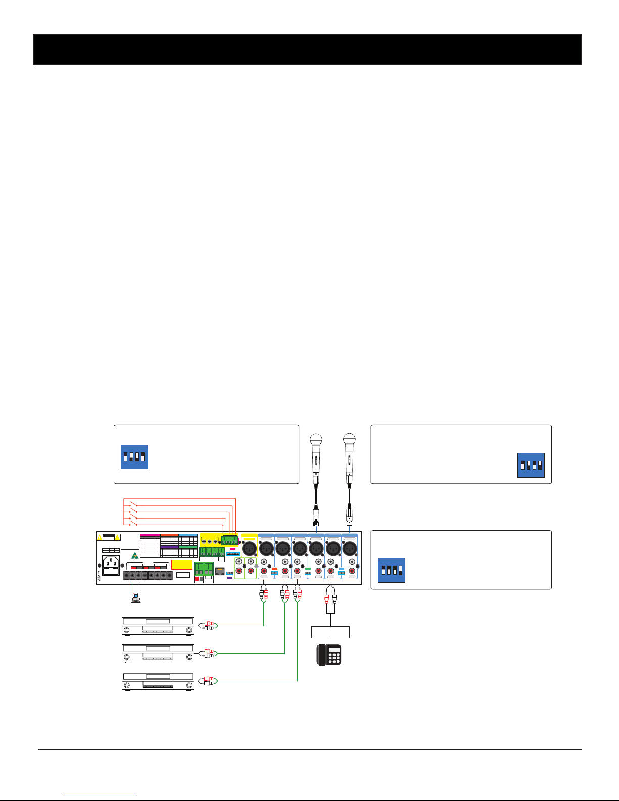
Figure 2.2A demonstrates an install with all 4 levels of priority shown. The A 4573 is tted and assumes level 2 priority.
Input 1 is shown with a microphone connected. The DIP1 switch settings are set for a 100mV sensitivity balanced micro-
phone input with the priority/VOX enabled which makes this input priority level 1. (Refer to section 2.3 for more details
about DIP switch settings). Input 2 is connected to a telephone paging system with a line level output. The DIP1 switch
settings are set for a line level input with 1V input sensitivity and the VOX enabled which makes this input priority level
3. Input 3 is shown with a microphone connected. The DIP2 switch settings are set for a balanced microphone input and
with the VOX enabled which makes this input priority level 4. Inputs 4-6 have no VOX option.
Fig 2.2A
Telephone Paging
System
Speakers tted with
100V line transformers.
CD
REDBACK
CD
REDBACK
CD
REDBACK
4 -16Ω70V100V
OUTPUTS
L
R
24V DC IN
Balanced Mic
+
_
PTT
(short to
activate)
Power Fail
(Contacts
close on
power fail)
SendReturn
Tape Out
Preamp Out
Link To Charge
Backup battery
Input 1Input 3 Input 2Input 4Input 5Input 6
ALERT - EVAC MODULE
Output Levels
Voice Chime Alert
O ver & Evac
EV COMCANCH
AL
Triggers
L
R
+
–
Rem. Vol
Connect
to 1KΩ Pot
+–+–+
–
Line
24V DC
Switched
Output
DIP 5
Interface
DIP 4
DIP 1
DIP 2DIP 3
Balanced Mic
Line
Balanced Mic
Line
Balanced Mic
Line
Balanced Mic
Line
Balanced Mic
Line
Balanced Line
LRL
R
LRL
R
L
2 1
3
2 1
3
2 1
3
2 1
3
2 1
3
2 1
3
2 1
3
1 2 3 4 5 6 7 8
1 2 3 4
1 2 3 4
1 2 3 4
1 2 3 4
230V AC @ 50Hz
www.altronics.com.au
RESETTABLE
DCFUSE
Made in Australia
by Altronic
Distributors
Pty Ltd
DIP 5
DIP 4
IMPORTANT NOTE
Ensure power is switched OFF when
adjusting DIP switches. New
settings will be eective when
power is switched back on.
DIP 3
SW Item On O
12Input 6 Level 1V 100mV
3
Not USed
4 Input 5 Level 1V 100mV
Not USed
1
2
3
4
DIP 2
SW Item On O
Input 4 Level 1V 100mV
Not USed
Input 3 Level 1V 100mV
Input 3 Priority On O
*
DIP 1
SW Item On O
12Input 2 Level 1V 100mV
3
Input 2 Priority On O
4 Input 1 Level 1V 100mV
Input 1 Priority On O
*
*
SW
Item On
O
1
2
3
4
Not Used
Not Used
Not Used
Not Used
DIP 4
DIP 1
DIP 2DIP 3
SW
Item On O
Switched 24VDC Out On O
Phantom Power Input 6 On O
On O
1
2
3
4
Phantom Power Input 5
On O
5
Phantom Power Input 4
On O
6
Phantom Power Input 3
On O
7
Phantom Power Input 2
On O
8
Phantom Power Input 1
Preamp Out
†
Post
Pre
†
Sets the Preamplier output to
Pre or Post Master.
DIP 5
Priority or VOX muting is only
functional on inputs 1-3. When
VOX is enabled on input 1 it will
override all other inputs including the Alert/Evac Module. VOX
enabled on input 2 will override
inputs 3-6. VOX enabled on input
3 will override inputs 4-6.
If the Alert/Evac module is tted
it will override inputs 2-6.
*
Model
125W
5AAC Fuse
250W
7.5A
AC Fuse Ratings
RISK OF ELECTRIC SHOCK
OPEN BY QUALIFIED
PERSONNEL ONLY
!
CAUTION
DIP 3
ON
1 2 3 4
DIP 1
ON
1 2 3 4
Evacuation Trigger
Alert Trigger
Chime Trigger
Cancel Trigger
Evacuation tones can
be triggered by closing
contacts such as switches,
from Fire Indicator Boards
or the like.
DIP 2
ON
1 2 3 4
Input 1 & 2 Settings
SW1 set to ON for 1V sensitivity on Input 2
SW2 set to ON to enable the VOX/priority
SW3 set to ON to enable the VOX/priority
SW4 set to OFF for 100mV sensitivity on Input 1
Input 5 & 6 Settings
SW1 set to ON for 1V sensitivity on Input 6
SW2 Not Used
SW3 Not Used
SW4 set to ON for 1V sensitivity on Input 5
Input 3 & 4 Settings
SW1 set to ON for 1V sensitivity on Input 4
SW2 Not Used
SW3 set to ON to enable the VOX/priority
SW4 set to OFF for 100mV sensitivity on Input 3
Page 14
www.altronics.com.auRedback® Proudly Made In Australia
14
2.3 DIP Switch settings
The A 4275/85 range of ampliers have a set of options which are enabled via the DIP switches 1-5.
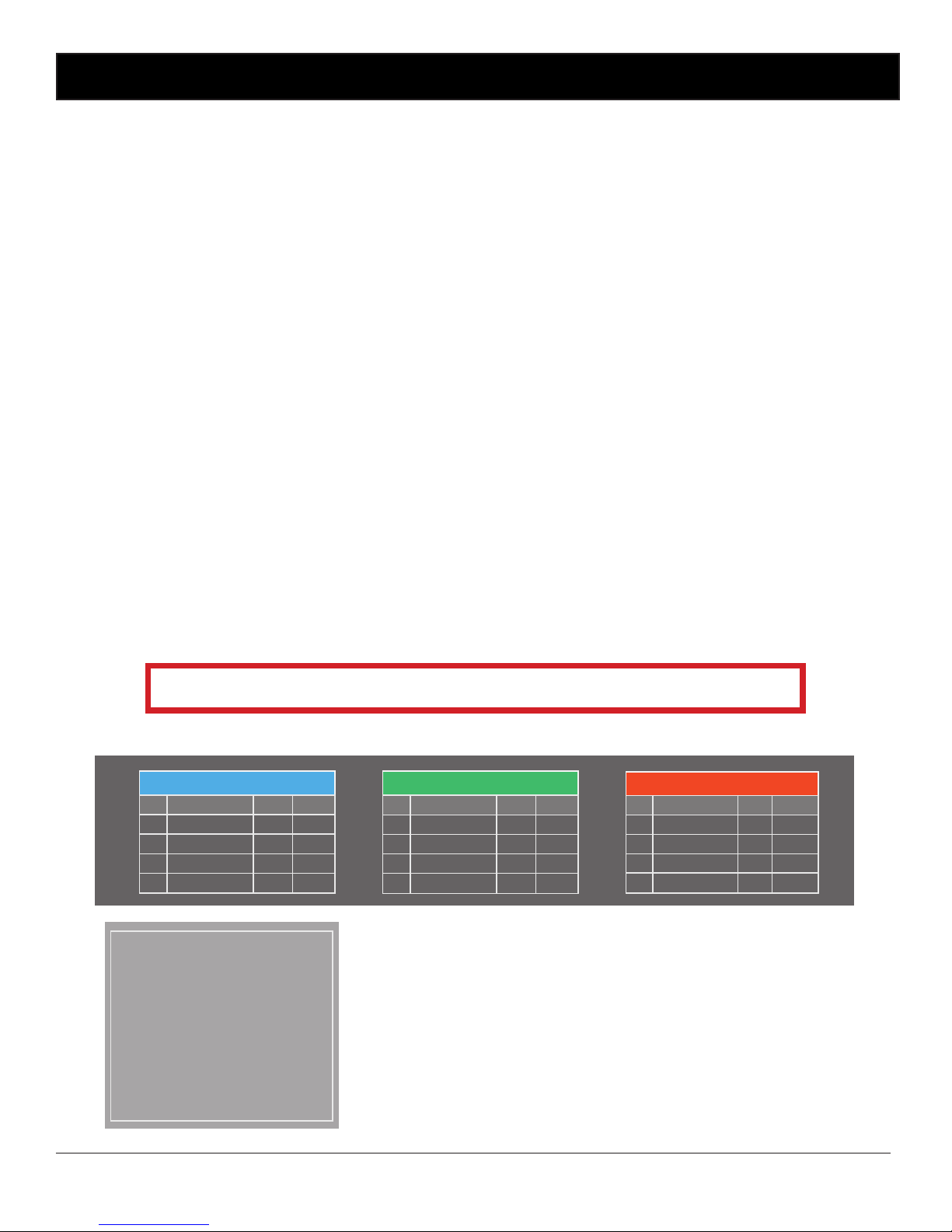
DIP 1-3 set the input level sensitivity and priorities for inputs 1-6 as outline below and in Fig 2.3A.
(* Priority/VOX muting is only available for inputs 1-3. Inputs 4-6 have no priority levels.)
DIP 1
Switch 1 - Sets Input 2 sensitivity to either 1V or 100mV. (This affects both the Balanced Mic and Line inputs)
Switch 2 - Sets Input 2 priority or VOX to ON or OFF.
Switch 3 - Sets Input 1 priority or VOX to ON or OFF.
Switch 4 - Sets Input 1 sensitivity to either 1V or 100mV. (This affects both the Balanced Mic and Line inputs)
DIP 2
Switch 1 - Sets Input 4 sensitivity to either 1V or 100mV. (This affects both the Balanced Mic and Line inputs)
Switch 2 - Not Used
Switch 3 - Sets Input 3 priority or VOX to ON or OFF.
Switch 4 - Sets Input 3 sensitivity to either 1V or 100mV. (This affects both the Balanced Mic and Line inputs)
DIP 2
Switch 1 - Sets Input 6 sensitivity to either 1V or 100mV. (This affects both the Balanced Mic and Line inputs)
Switch 2 - Not Used
Switch 3 - Not Used
Switch 4 - Sets Input 5 sensitivity to either 1V or 100mV. (This affects both the Balanced Mic and Line inputs)
Input 1: When VOX is enabled on input 1 it will override all other inputs (including the optional A 4573 alert/evac
module).
Input 2: When VOX is enabled on input 2 it will override inputs 3 to 6 ).
Input 3: When VOX is enabled on input 3 it will override inputs 4 to 6.
Inputs 4-6: No VOX
To adjust the VOX sensitivity levels see section 2.4.
Please Note : If the Alert/Evac Tone Module (A 4573) is tted its VOX will always be enabled.
It will override inputs 2 to 6 when activated.
Setup
Fig 2.3A
Fig 2.3B
DIP 3
SW Item On O
12Input 6 Level 1V 100mV
3
Not USed
4 Input 5 Level 1V 100mV
Not USed
DIP 2
SW Item On O
12Input 4 Level 1V 100mV
3
Not USed
4 Input 3 Level 1V 100mV
Input 3 Priority On O
*
DIP 1
SW Item On O
12Input 2 Level 1V 100mV
3
Input 2 Priority On O
4 Input 1 Level 1V 100mV
Input 1 Priority On O
*
*
Priority or VOX muting is only
functional on inputs 1-3. When
VOX is enabled on input 1 it will
override all other inputs including the Alert/Evac Module. VOX
enabled on input 2 will override
inputs 3-6. VOX enabled on input
3 will override inputs 4-6.
If the Alert/Evac module is tted
it will override inputs 2-6.
*
Page 15
www.altronics.com.au Redback® Proudly Made In Australia
15
Setup
DIP 4
These are currently not used.
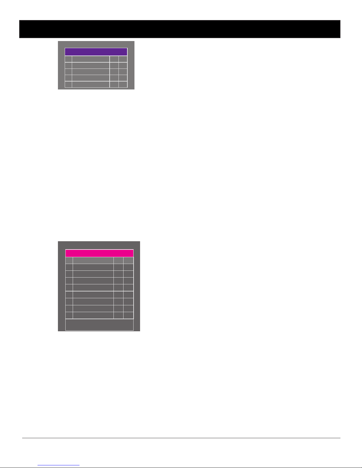
DIP 5
This congures the 24V DC switched out status, determines the output of the Preamp Out and sets the phantom power
to the inputs. See Fig 2.3C for details.
Switch 1- Sets the switched 24V DC out to ON or OFF. IF set to ON the switched output will activate whenever the
PTT contacts are triggered or when a priority/VOX is activated.
Switch 2 - The Preamp output can be set up to be effected (post master volume) by the master volume control or
unaffected (pre master volume).
Switch 3- Sets the phantom power (15V DC) for input 6.
Switch 4- Sets the phantom power (15V DC) for input 5.
Switch 5- Sets the phantom power (15V DC) for input 4.
Switch 6- Sets the phantom power (15V DC) for input 3.
Switch 7- Sets the phantom power (15V DC) for input 2.
Switch 8- Sets the phantom power (15V DC) for input 1.
2.4 Adjusting VOX levels
The VOX sensitivity levels for inputs 1-3 sensitivity can all be adjusted via trimpots accessed through the front panel.
DIP4 Switch Settings
SW
Item On
O
1
2
3
4
Not Used
Not Used
Not Used
Not Used
DIP 4
DIP5 Switch Settings
SW
Item On O
Switched 24VDC Out On O
Phantom Power Input 6 On O
On O
1
2
3
4
Phantom Power Input 5
On O
5
Phantom Power Input 4
On O
6
Phantom Power Input 3
On O
7
Phantom Power Input 2
On O
8
Phantom Power Input 1
Preamp Out
†
Post
Pre
†
Sets the Preamplier output to
Pre or Post Master.
DIP 5
Fig 2.3B
Fig 2.3C
Page 16
www.altronics.com.auRedback® Proudly Made In Australia
16
Setup
Fig 2.5A
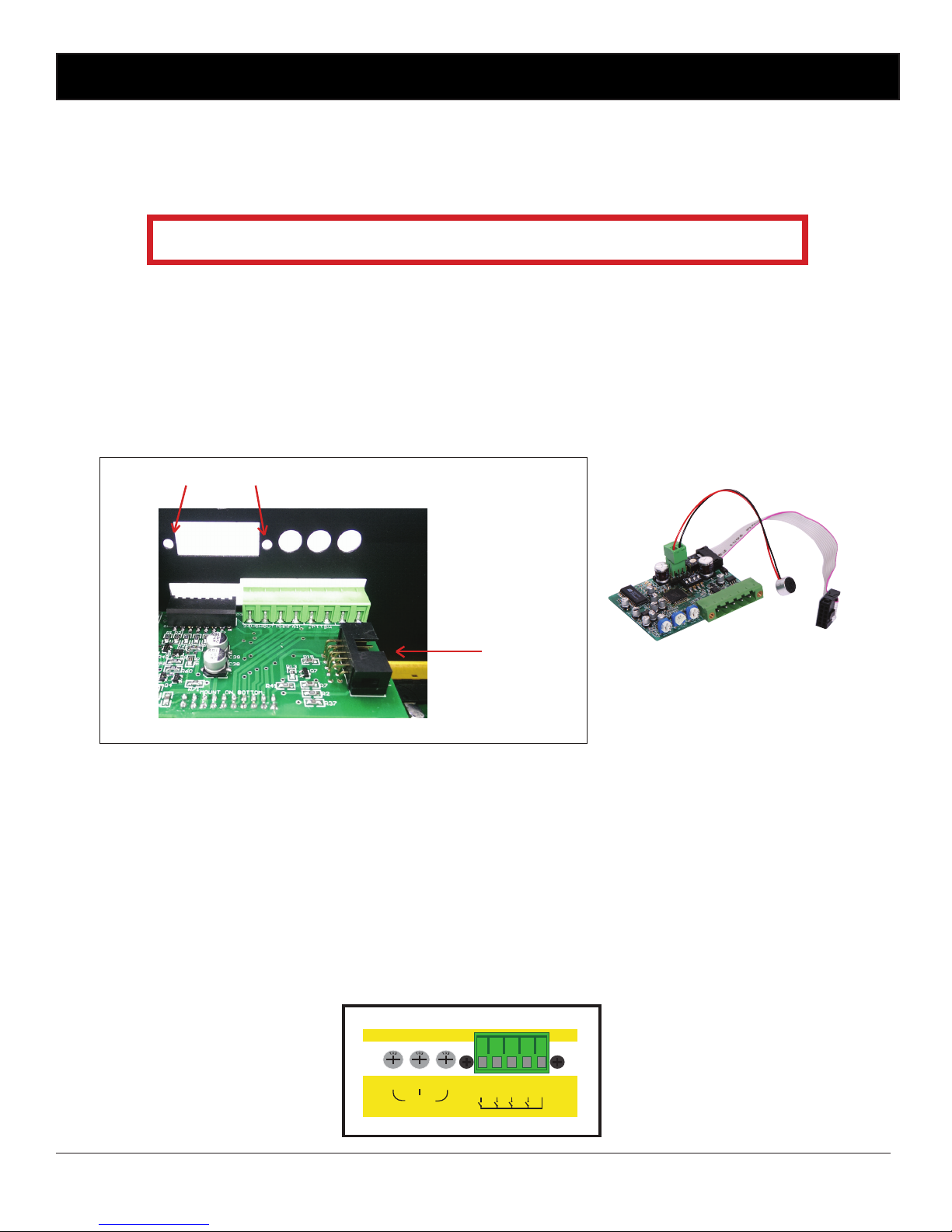
2.5 Installing the A 4573 optional Alert/Evac Module
The A 4573 module provides a means of adding Alert, Evacuation and chime tones to the amplier. A voice-over message can also be recorded and played back during the evacuation tone cycle. All alert and evacuation tones comform to
Australian standard AS1607.4.
NOTE: If the Alert/Evac Tone Module (A 4573) is tted its VOX will always be enabled.
It will override inputs 2 to 6 when activated.
To install the tone generator follow these steps.
1. Remove the lid from unit
2. Unscrew the tone generator cover plate from the rear panel
3. Locate tone generator 10 way header on board (this is located at the rear of the main board)
4. Connect ribbon cable header to the 10 way header on the rear board of mixer (see g 2.5A).
5. The tone generator is held in by way of 2 screws (supplied) through the rear panel (via the same holes that the
tone generator cover plate was attached).
6. Ret lid and secure with screws.
NOTE: Tones are operated by closing contacts and remain operating whilst contacts are closed.
Fig 2.5B shows the volume controls and the triggers.
1 Voice Over Volume
Use this trimpot adjustment to change the output level of the playback message.
2 Chime Volume
Use this trimpot adjustment to change the output level of the chime volume.
3 Alert and Evacuation Volume
Use this trimpot adjustment to change the output level of the alert and evacuation tone.
4 Alert, Evacuation, chime and cancel contacts
Use these contacts to trigger the chime tones, the alert tone, the evacuation tone and to cancel any
of the tones once triggered. All tones & cancel function are operated by a closing contact to ground.
This could be triggered via building re indicator board, break glass alarm etc.
Output
Voice Chime Alert
Over & Evac
ALERT - EVACUATION MODULE
EVAC
COM
CAN
CHIME
ALERT
Triggers
Levels
Fig 2.5B
A 4573
10 Way
Header
Screw Holes
Page 17
www.altronics.com.au Redback® Proudly Made In Australia
17
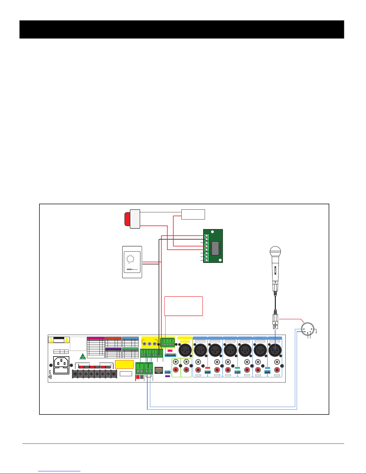
2.6 PTT and 24V DC Switched Output
24V DC is available as a switched output to control external devices like remote volume controls with bypass relays for
emergency paging or evacuation strobes (when powered from an external 24V supply). Please note: The 24V DC switched
output has a maximum current draw of 1 amp and is internally thermal fuse protected.
Fig 2.6 demonstrates the connection of a strobe to the 24V DC output. As the current draw of the strobe may be more
than 1amp a relay board is used to switch an external power supply. The Altronics S 4444 24V Relay Board as shown is an
inexpensive and easily installed option designed for this purpose.
To enable the switched output, switch 1 on DIP5 must be set to the “ON” position.
The 24V DC ouput is activated when the PTT terminals shown on the rear of the unit (see Fig 2.6) are shorted together or
when any priority/VOX is activated. The PTT is normally done with the switch of a push to talk microphone as shown in
Fig 2.6.
Fig 2.6
Setup
4 -16Ω70V100V
OUTPUTS
L
R
24V DC IN
Balanced Mic
+
_
PTT
(short to
activate)
Power Fail
(Contacts
close on
power fail)
SendReturn
Tape Out
Preamp Out
Link To Charge
Backup battery
Input 1Input 3 Input 2Input 4Input 5Input 6
ALERT - EVAC MODULE
Output Levels
Voice Chime Alert
Over & Evac
EV COMCANCH
AL
Triggers
L
R
+
–
Rem. Vol
Connect
to 1KΩ Pot
+–+–+
–
Line
24V DC
Switched
Output
DIP 5
Interface
DIP 4
DIP 1
DIP 2DIP 3
Balanced Mic
Line
Balanced Mic
Line
Balanced Mic
Line
Balanced Mic
Line
Balanced Mic
Line
Balanced Line
L
R
L
R
L
R
L
R
L
R
2 1
3
2 1
3
2 1
3
2 1
3
2 1
3
2 1
3
2 1
3
1 2 3 4 5 6 7 8
1 2 3 4
1 2 3 4
1 2 3 4
1 2 3 4
230V AC @ 50Hz
www.altronics.com.au
RESETTABLE
DC FUSE
Made in Australia
by Altronic
Distributors
Pty Ltd
DIP 5
DIP 4
IMPORTANT NOTE
Ensure power is switched OFF when
adjusting DIP switches. New
settings will be eective when
power is switched back on.
DIP 3
SW Item On O
12Input 6 Level 1V 100mV
3
Not USed
4 Input 5 Level 1V 100mV
Not USed
1
2
3
4
DIP 2
SW Item On O
Input 4 Level 1V 100mV
Not USed
Input 3 Level 1V 100mV
Input 3 Priority On O
*
DIP 1
SW Item On O
12Input 2 Level 1V 100mV
3
Input 2 Priority On O
4 Input 1 Level 1V 100mV
Input 1 Priority On O
*
*
SW
Item On
O
1
2
3
4
Not Used
Not Used
Not Used
Not Used
DIP 4
DIP 1
DIP 2DIP 3
SW
Item On O
Switched 24VDC Out On O
Phantom Power Input 6 On O
On O
1
2
3
4
Phantom Power Input 5
On O
5
Phantom Power Input 4
On O
6
Phantom Power Input 3
On O
7
Phantom Power Input 2
On O
8
Phantom Power Input 1
Preamp Out
†
Post
Pre
†
Sets the Preamplier output to
Pre or Post Master.
DIP 5
Priority or VOX muting is only
functional on inputs 1-3. When
VOX is enabled on input 1 it will
override all other inputs including the Alert/Evac Module. VOX
enabled on input 2 will override
inputs 3-6. VOX enabled on input
3 will override inputs 4-6.
If the Alert/Evac module is tted
it will override inputs 2-6.
*
Model
125W
5AAC Fuse
250W
7.5A
AC Fuse Ratings
RISK OF ELECTRIC SHOCK
OPEN BY QUALIFIED
PERSONNEL ONLY
!
CAUTION
Attenuator tted with
over-ride relay
Evacuation strobe
Balanced
Audio
PTT
5
1
4 2
3
DIP5 - Switch 1 set to “ON”
to enable 24V DC
switched OUT.
5 Pin Microphone
with a PTT switch.
+24V
GND
24V Relay Board
(Altronics S 4444)
N/C1
N/C2
N/O2
N/O1
COM1
COM2
External
24V DC Supply
+24V
GND
Page 18
www.altronics.com.auRedback® Proudly Made In Australia
18
Setup
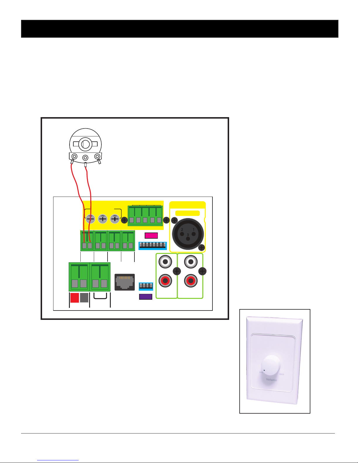
2.7 Remote Volume Connection
A two way euro block terminal has been provided for the connection of a remote volume control.
A potentiometer needs to be wired to these two terminals.
**DO NOT LINK OR SHORT THESE TERMINALS**
A 1KΩ potentiometer is required for the remote volume to work correctly. The Altronics A 2280B shown below would be
suitable.
The maximum distance from the amplier the potentiometer can be connected is 100 metres. Fig 2.7 shows a typical
connection.
Altronics A 2280B
(Wallplate tted with 1KΩ
Potentiometer)
Fig 2.7
DIP 5
DIP 4
24V DC IN
+
_
PTT
(short to
activate)
Power Fail
(Contacts
close on
power fail)
SendReturn
Tape Out
Preamp Out
Link To Charge
Backup battery
ALERT - EVAC MODULE
Output Levels
Voice Chime Alert
O ver & Evac
EV COMCANCH
AL
Triggers
L
R
+
–
Rem. Vol
Connect
to 1KΩ Pot
24V DC
Switched
Output
Interface
Balanced Line
2 1
3
1 2 3 4 5 6 7 8
1 2 3 4
1KΩ Potentiometer
Page 19
www.altronics.com.au Redback® Proudly Made In Australia
19
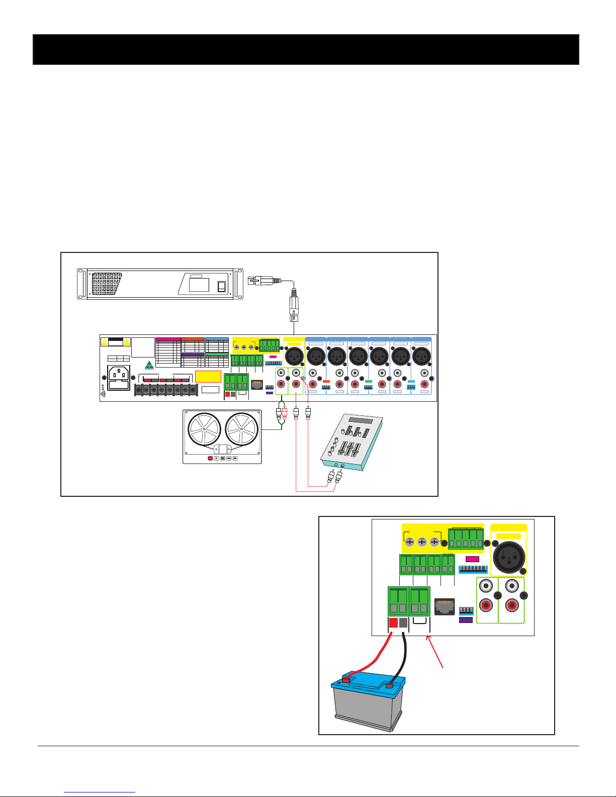
2.8 Pre-Amp Out, Tape Out, Send & Return
Pre-Amp Out
A 3 pin 600ohm 1V balanced XLR output is provided for passing the audio signal on to other slave ampliers or to record
the output of the amplier. This output can be set up to be effected (post master volume) by the master volume control or
unaffected (pre master volume). Factory default setting disables the preout. (Refer to section 2.3 DIP switch settings).
Tape Out
Dual RCA’s are provided for the “Tape Out” connection for recording purposes. This level is post master volume so it is
affected by the master volume.
Send and Return
RCA connectors are provided for the send and return audio paths. This allows external effects units, ie Graphic EQ’S ,
companders or signal processors to be connected to the amplier. When not using this feature the send and return
outputs must be linked externally (this is factory tted). The amplier will not work without this link. Only when an
external effects unit is used can it be removed.
Fig 2.8 illustrates the connections required for a slave amplier, a recording unit and an effects unit.
2.9 Backup Battery Charging
If the amplier is connected to backup batteries the amplier
is provided with a trickle charge circuit to maintain the batteries in a charged condition. The charge rate is approximately
300mA. Simply link the terminals marked “link to charge
backup battery” on the rear of the amplier. A at battery will
generally take overnight to charge, or even longer depending
on the battery capacity. (Refer to g 2.9 for connection details)
Fig 2.8
Setup
4 -16Ω70V100V
OUTPUTS
L
R
24V DC IN
Balanced Mic
+
_
PTT
(short to
activate)
Power Fail
(Contacts
close on
power fail)
SendReturn
Tape Out
Preamp Out
Link To Charge
Backup battery
Input 1Input 3 Input 2Input 4Input 5Input 6
ALERT - EVAC MODULE
Output Levels
Voice Chime Alert
Over & Evac
EV COMCANCH
AL
Triggers
L
R
+
–
Rem. Vol
Connect
to 1KΩ Pot
+–+–+
–
Line
24V DC
Switched
Output
DIP 5
Interface
DIP 4
DIP 1
DIP 2DIP 3
Balanced Mic
Line
Balanced Mic
Line
Balanced Mic
Line
Balanced Mic
Line
Balanced Mic
Line
Balanced Line
LRL
R
LRL
R
L
2 1
3
2 1
3
2 1
3
2 1
3
2 1
3
2 1
3
2 1
3
1 2 3 4 5 6 7 8
1 2 3 4
1 2 3 4
1 2 3 4
1 2 3 4
230V AC @ 50Hz
www.altronics.com.au
RESETTABLE
DCFUSE
Made in Australia
by Altronic
Distributors
Pty Ltd
DIP 5
DIP 4
IMPORTANT NOTE
Ensure power is switched OFF when
adjusting DIP switches. New
settings will be eective when
power is switched back on.
DIP 3
SW Item On O
12Input 6 Level 1V 100mV
3
Not USed
4 Input 5 Level 1V 100mV
Not USed
1
2
3
4
DIP 2
SW Item On O
Input 4 Level 1V 100mV
Not USed
Input 3 Level 1V 100mV
Input 3 Priority On O
*
DIP 1
SW Item On O
12Input 2 Level 1V 100mV
3
Input 2 Priority On O
4 Input 1 Level 1V 100mV
Input 1 Priority On O
*
*
SW
Item On
O
1
2
3
4
Not Used
Not Used
Not Used
Not Used
DIP 4
DIP 1
DIP 2DIP 3
SW
Item On O
Switched 24VDC Out On O
Phantom Power Input 6 On O
On O
1
2
3
4
Phantom Power Input 5
On O
5
Phantom Power Input 4
On O
6
Phantom Power Input 3
On O
7
Phantom Power Input 2
On O
8
Phantom Power Input 1
Preamp Out
†
Post
Pre
†
Sets the Preamplier output to
Pre or Post Master.
DIP 5
Priority or VOX muting is only
functional on inputs 1-3. When
VOX is enabled on input 1 it will
override all other inputs including the Alert/Evac Module. VOX
enabled on input 2 will override
inputs 3-6. VOX enabled on input
3 will override inputs 4-6.
If the Alert/Evac module is tted
it will override inputs 2-6.
*
Model
125W
5AAC Fuse
250W
7.5A
AC Fuse Ratings
RISK OF ELECTRIC SHOCK
OPEN BY QUALIFIED
PERSONNEL ONLY
!
CAUTION
POWER
REDBACK
A 4270 125W
Public Address Amplie
PHASE
5
SLAVE AMPLIFIER
EFFECTS UNIT
RECORDER
LINK THESE TERMINALS
+
-
24V DC IN
+
_
PTT
(short to
activate)
Power Fail
(Contacts
close on
power fail)
SendReturn
Tape Out
Preamp Out
Link To Charge
Backup battery
ALERT - EVAC MODULE
Output Levels
Voice Chime Alert
O ver & Evac
EV COMC ANCH
AL
Triggers
L
R
+
–
Rem. Vol
Connect
to 1KΩ Pot
24V DC
Switched
Output
DIP 5
Interface
Balanced Line
2 1
3
1 2 3 4 5 6 7 8
1 2 3 4
DIP 5
DIP 4
Fig 2.9
Page 20
www.altronics.com.auRedback® Proudly Made In Australia
20
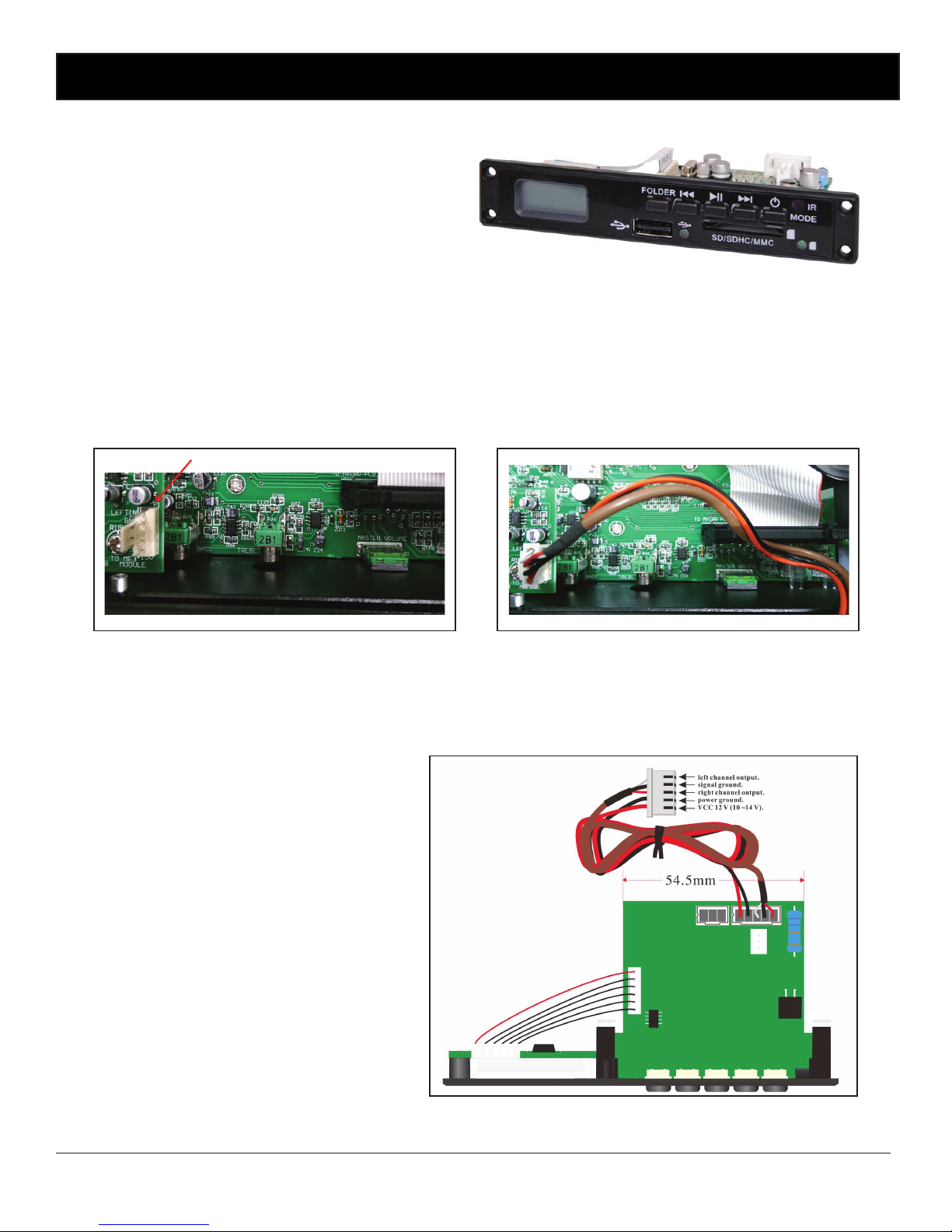
2.10 Fitting the Optional A 2711 MP3 Module
To install the optional MP3 module, follow these steps.
1. Make sure the amplier is turned off.
2. Remove the lid from unit.
3. Unscrew the front cover piece from the front
panel (keep the screws).
4. Locate the header inside the front of the
amplier. See Fig 2.10A
5. Push the header cable from the A 2711 MP3 module through the front panel and connect it to the 5 way header
on the front board of the mixer (see g 2.10B). Take special attention of the orientation of the plug.
6. Screw the module in using the four screws removed from the front cover piece.
7. Ret lid and secure with screws.
Once tted if music is playing from this module it will over-ride the rear input 6. The output level is adjusted via the
volume 6 control on the front of the amplier.
NOTE: If a music source is connected to the Music input on the front of the amplier it will override this MP3 Module and
the rear input 6 source.
A 2711 Specications A 2711 Pinouts
Output level: 500mV(800mV volume max.)
Playback frequency: 20Hz - 19KHz
THD: <0.3%
Signal to noise ratio: >65dB
File types: MP3/WMA/WAV
MP3/WMA decoder: 32-320kbps decoding
WAV decoder:
PCM single track 128-768kbps
PCM double track 256-1536kbps
IMA-ADPCM single track 32-192kbps
IMA-ADPCM double track 64-384kbps
Storage: USB/SD Card (maximum 32GB - FAT16/32)
Supply voltage: 12V DC(10-15V operating range)
Power consumption: <2W
Dimensions: 120W x 56.5D x 22Hmm
Setup
A 2711 Header
Fig 2.10A Fig 2.10B
Page 21
www.altronics.com.au Redback® Proudly Made In Australia
21
Setup
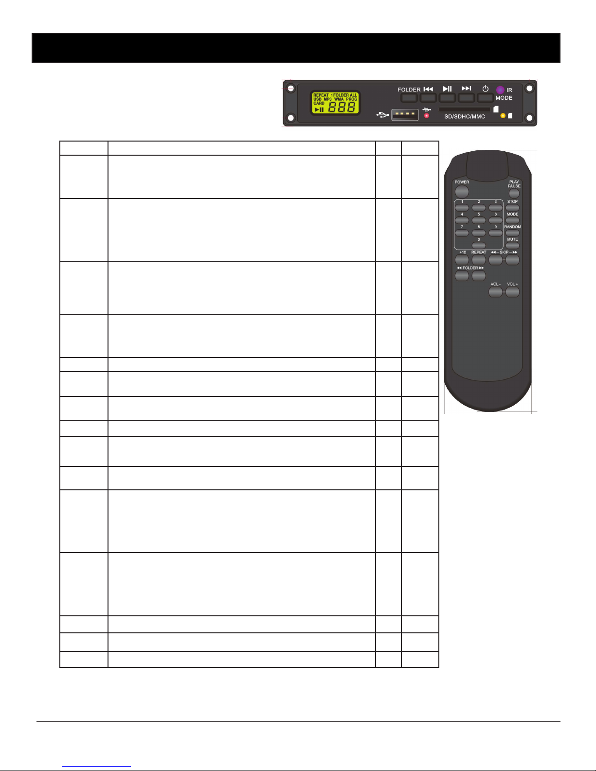
A 2711 Controls
The MP3 module can be controlled via the supplied remote
control or by the buttons on the front of the A 2711. The table
below lists the various functions and the means to control
them.
Keys
Explanation Panel Remote
PLAY/
PAUSE
When this key is pushed during USB/SD stop, play will start after track
search. When this key is pushed during USB/SD is playing, then it is
changed to pause. When this key is pushed during USB/SD is pausing,
then it is changed to play
√ √
FAST
FOR-
WARD
In stop mode: Change the starting play track (le) during stop mode,
cyclic to the rst track, if it is in the last track.
In play mode, pause mode, random play mode: Single pressed, skip the
playing track (le) to next track (le) for normal play/pause mode, to next
random track (le) for random play /pause mode.Continue pressed, fast
forward during play/pause when pressed more than 2sec.
√ √
REWIND
In stop mode: Change the starting play track (le) during stop mode,
cyclic to the last track, if it is in the rst track.
In play mode, pause mode: Single pressed, skip the playing track (le) to
precious track (le) for normal play/pause mode. Continue pressed, fast
reverse during play/pause when pressed more than 2sec.
√ √
MODE
When the module is in ON state, pressing this key will change mode
between USB and SD.Pressing this key over 3 seconds will power off the
module.When the module is in the OFF state, pressing this key will power
on the module.
√
POWER
Power off the module. √
STOP
When in PLAY/PAUSE mode, pressing the stop key the will stop the player
and shows TOC.
√
MODE
When this key is pressed shortly, the module mode will change between
USB, CARD and FM.
√
+10
Pressing this key will skip forward 10 MP3 les √
RANDOM
When this key is pressed the module will play tracks
randomly. If the key is pressed again random mode will be cancelled.
√
MUTE
The module will mute when this key is pressed. Of the key is pressed
again, mute mode will be cancelled.
√
FOLDER
UP
In stop mode: Skip the starting play folder to next folder during stop
mode, cyclic to the rst folder if it is in the last folder.
In program entry mode: Change the le for program select to next folder’s rst le, cyclic to the rst folder if it is in the last folder.
In normal play mode: Skip the playing le to the next folder’s rst le.
√ √
FOLDER
DOWN
In stop mode: Skip the starting play folder to previous folder during stop
mode, cyclic to the last folder if it is in the rst folder.
In program entry mode: Change the le for program select to previous
folder’s rst le, cyclic to the last folder if it is in the rst folder.
In normal play mode: Skip the playing le to the previous folder’s rst le.
√ √
VOL -
Long press this key, the volume will decrease. √
VOL +
Long press this key, the volume will increase. √
0 - 9
You can use these keys to select the track you want directly. √
Page 22

www.altronics.com.auRedback® Proudly Made In Australia
22
3.0 TROUBLE SHOOTING
If the REDBACK Phase 4 amplier fails to deliver the rated performance, check the following:
No Power, No Lights
Make sure amplier power switch is on. Make sure mains power switch is on at the wall. Check the mains and DC fuse.
Replace with only the correct type and rating. Over rated fuses with invalidate warranty.
Distorted Output
Check that the speaker type is correct for the output that you are using (ie. 4-16O, 70V or 100V line). Check for any short
circuits on the speaker line.
Very Low Output Volume
Make sure that the input is the correct level (check for shorted connectors). Check for any short circuits on the speaker
line.
Check input DIP switches are set correctly.
Check if signal LED on the front panel is lit to indicate there is signal. If it is not lit there is no signal present.
Continually Blows Fuses
Make sure that the speaker line is not shorted. Check speaker types, ratings and if on correct output.
Amplier Keeps on Cutting In & Out
Make sure that there is adequate ventilation around the amplier. Check the vent slots on the front,top and sides are not
covered or blocked and the fan on the rear is functioning correctly. Check also speaker types, ratings and for any short
circuits on the speaker line.
No Output Volume
Check the Send/Return link is in place. Ensure the input selector dip switch is congured correctly for each corresponding
input.
Ensure remote volume terminals are linked when no remote volume potentiometer is connected.
When connected, check remote volume control is not turned down.
No Switched 24V DC
Check output switch for correct setting.
Check fuse located on rear PCB is not blown (located inside the unit). see section 2.6 for details.
Troubleshooting
Page 23

www.altronics.com.au Redback® Proudly Made In Australia
23
Specications
4.0 SPECIFICATIONS
POWER OUTPUTS
A 4275: .................................125 watts RMS
A 4285: .................................250 watts RMS
Distortion:..........................< 0.5%, @ 1kHz
Output line: ...............70V, 100V or 4 - 16O
Line output:..............600O balanced, 0dBV
FREQUENCY RESPONSE
Mic inputs:....................50Hz - 12kHz, -3dB
Line inputs: ..................50Hz - 15kHz, -3dB
SENSITIVITY
Mic inputs: ............................3mV balanced
Line inputs:.................................100mV-1V
SIGNAL TO NOISE RATIO
Mic inputs: .........> 75dB below rated output
Line inputs:........> 81dB below rated output
OUTPUT CONNECTORS
Speakers: ...........................Screw terminals
Line out: .......................................3 pin XLR
INPUT CONNECTORS
Inputs: ........3 pin XLR balanced or 2 x RCA
24V DC power: ...................Screw terminals
240V AC power: .........IEC power connector
Muting:PTT via microphone switch contacts
or VOX muting (inputs 1-3)
CONTROLS
Mic inputs: .......................................Volume
Line inputs:......................................Volume
Bass:..................................±10dB @ 100Hz
Treble:................................±10dB @ 10kHz
Master: .............................................Volume
Power: .....................................On/off switch
Indicators:...............Power, fault, VU meter,
signal present, output peak limiting, overtemp
Power Supply: .............240V AC or 24V DC
FUSE PROTECTION
A 4275: ...............................5A AC , 10A DC
A 4285: ............................7.5A AC , 20A DC
Switched 24VDC 1A Internal (both models)
DIMENSIONS
All models: ................≈483W x 330D x 88H
WEIGHT
A 4275: ............................................≈14.5kg
A 4285: ............................................≈19.5kg
Colour:.................................................Black
*Specications subject to change without notice
Page 24
www.altronics.com.auRedback® Proudly Made In Australia
24
All Australian made Redback products are covered by a 10 year warranty.
Should a product become faulty please contact us to obtain a return authorisation number. Please ensure you have all
the relevant documentation on hand. We do not accept unauthorised returns. Proof of purchase is required so please
retain your invoice.
Warranty
SPRINGV
ALE RD
PRINCES H’WAY
HARCOURT AV
ALBERT CR
KALMINA AV
WESTALL RD
GARDEN R
CENTRE RD
ROE ST
FITZGERALD ST
JAMES ST
Northbridge
Perth GPO
1km
PARRAMATTA RD
DUCK ST
SHORT ST
MEGA MALL
Sydney GPO
Auburn
20km
MITCHELL FWY
Balcatta
ERINDALE RD
BOYA WAY
LEDGAR RD
DELAWNEY ST
Sydney, NSW.
15 Short St, AUBURN,
NSW 2144
Open:
Mon-Fri 8.30am - 5.30pm
Sat 9.00am - 4.00pm
Melbourne, Vic.
891 Princes Hwy, SPRINGVALE,
VIC 3171
Open:
Mon-Fri 8.30am - 5.30pm
Sat 9.00am - 5.00pm
Sun 10.00am - 4.00pm
Perth, WA.
174 Roe St, PERTH, WA 6000
Open:
Mon-Wed,Fri 8.00am - 5.30pm
Thur 8.00am - 8.00pm
Sat 8.30am - 5.00pm
Sun 12.00pm - 5.00pm
Virginia
SANDGATE ROAD
MCDONALDS
ROBINSON RD EA.
PRITCHARD ROAD
VAUXHALL ST
Brisbane
GPO 17km
Brisbane, Qld.
Unit 2, 1870 Sandgate Rd,
VIRGINIA, QLD 4014
Open:
Mon-Wed,Fri 8.00am - 5.30pm
Thur 8.00am - 8.00pm
Sat 8.30am - 5.00pm
Sun 10.00am - 4.00pm
Balcatta, WA.
Unit 7, 58 Erindale Rd,
BALCATTA, WA 6021
Open:
Mon-Fri 8.00am - 5.30pm
Sat 8.30am - 5.00pm
Sun 10.00am - 4.00pm
Cannington
CECIL AVE
ALBANY HWY
WHARF ST
MASON ST
FLETCHER ST
LEILA ST
BUNNINGS
CAROUSEL
Cannington, WA.
Unit 6, 1326 Albany Highway,
CANNINGTON, WA 6107
Open:
Mon-Wed,Fri 8.00am - 5.30pm
Thur 8.00am - 8.00pm
Sat 8.30am - 5.00pm
Ph: 1300 797 007 Fax: 1300 789 777
www.altronics.com.au
Retail / Trade / Education & Government customers
 Loading...