

Page 1

Ticket Printer
Ithaca® 850
for use in Atronic Cashline™
and e-motion™ gaming machines
Rev. 1.0
April 2005
Page 2

2
April 2005
Ticket Printer Ithaca
®
850
Ticket Printer
Ithaca® 850
for use in Atronic Cashline™ and e-motion™ gaming machines
Rev. 1.0
Rel. April 2005
© 2005 Atronic International GmbH. All rights reserved
RELEASE INFO
Page 3

3
April 2005
Ticket Printer Ithaca
®
850
Ticket Printer Ithaca® 850
for use in Atronic gaming machines
Introduction
This manual covers printer specifications and
operating- and maintenance procedures for servicing
the Ithaca 850 printer for use in Atronic gaming
machines.
Features
• High quality printing
• No consumable print cartridge
• Modular printer mechanism for easy maintenance
• Self diagnostics
• Easy ticket loading
• Ticket out sensing
• Black dot sensing (Top of Form)
• Ticket box (200 tickets) with ticket low sensor
(paper low status below 30 - 35 tickets).
Components
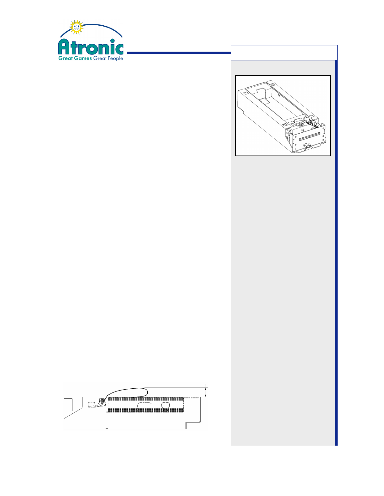
1. Printer Mechanism
2. Printer Mechanism Assembly
3. Printer Ticket Bucket (200)
4. Outer Slide Chassis
INTRODUCTION
Page 4
4
April 2005
Ticket Printer Ithaca
®
850
Ithaca 850 - Technical Data
Dimensions: Height: 67.6 mm (2.66")
Width: 113.3 mm (4.46")
Depth: 285.8 mm (11.25")
Weigth: 2.4 kg (5.3 lbs)
Printer type: Fixed 2.25" linear thermal head
Printer life: 20 million print lines
Print speed: max. 125 mm/sec. (text mode)
Resolution: 203 x 203 dpi, 136 x 203 dpi
Interface: Bi-directional, serial RS-232
Environmental conditions
Operating temperature range: 0° - 40°C (32° - 77°F)
Storage temperature range: -10° - 50°C (14° - 122°F)
Operating humidity range: 10% - 90% noncondensing
Power requirement: 24 V DC, max. 2.2 A
Ticket specification
Dimensions Width: 65 ± 0.75 mm (2.56 ± 0.03")
Length: 156 ± 1 mm (6.14 ± 0.04")
Thickness: 114 microns (0.0045")
Weigth: 102 g/m²
Ticket type: Kanzaki TO-381N or approved equivalent
Thermal sensitive layer facing down
Fan folded stack of 200 tickets
Ticket clearance
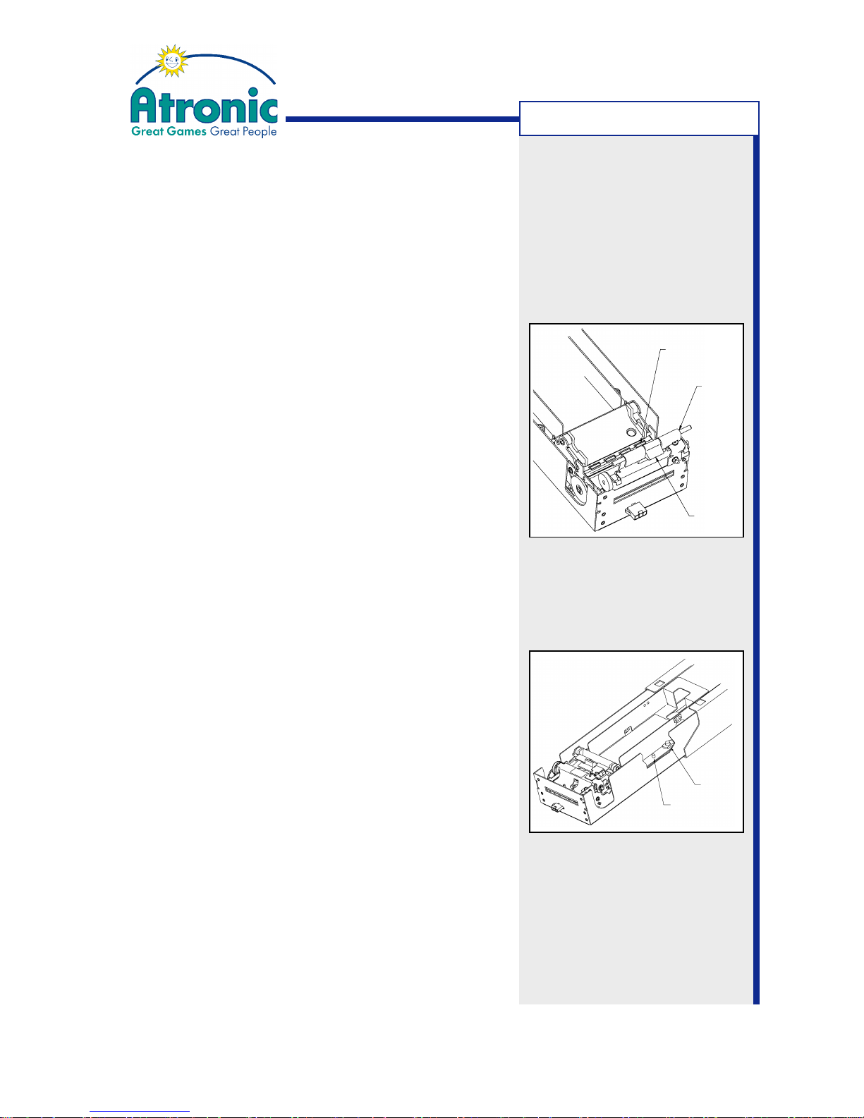
A minimum paper clearance of approx. 20 mm (0.75")
is required above the printer's ticket bucket. Consider
this when installing online system equipment to a
machine top box where a printer is installed.
20 mm
TECHNICAL DATA
Page 5
5
April 2005
Ticket Printer Ithaca
®
850
Remove loaded tickets
The Ithaca 850 printer has two ways to remove unused
tickets from the printer mechanism assembly.
• Unload tickets by opening the platen/cover assembly
• Unload tickets using the feed button
Unload tickets by opening the platen/cover
assembly
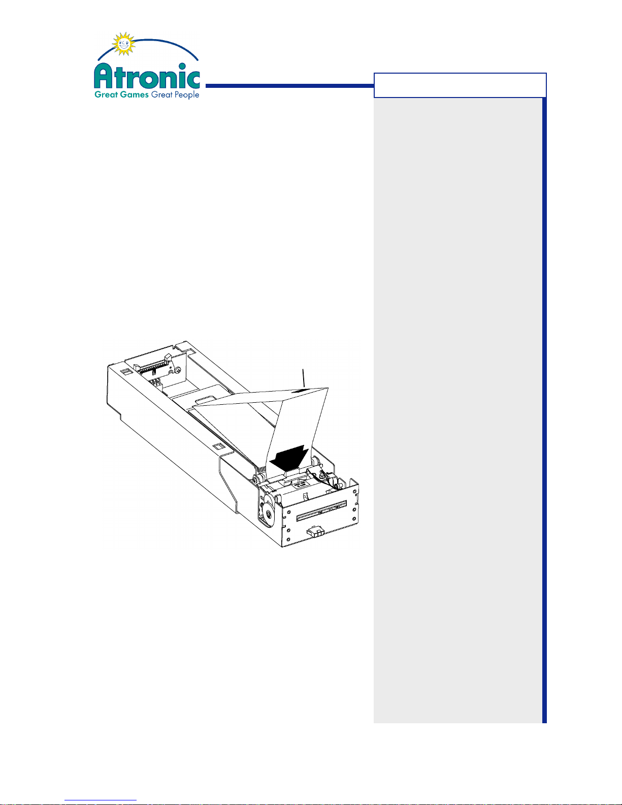
1. Pull the printer mechanism assembly out off the
slide chassis until it stops in open position.
2. Pull the plastic actuator latch towards the front of
the printer.
3. Swing the platen/cover assembly up and towards
the front of the printer.
4. Remove all tickets from the ticket path and check
for any debris.
5. Press the green label to relatch the platen/cover
assembly.
6. Proceed with ticket loading procedure.
Unload tickets using the feed button
1. Pull the printer mechanism assembly out off the
slide chassis until it stops in open position.
2. Seperate ticket currently loaded in the platen/cover assembly from the ticket stack and remove the
ticket stack.
3. Press the feed button to eject the ticket.
4. Proceed with ticket loading procedure.
platen/cover
assembly
print head
Actuator latch
Feed button
LED Indicator
OPERATING
Page 6
6
April 2005
Ticket Printer Ithaca
®
850
Ticket loading procedure
1. Make sure that there is power to the printer and
slide the printer mechanism assembly towards
open position, so that the assembly is unseated
from the outer slide chassis' racking retainer.
2. Remove any loaded tickets remaining from the old
ticket stack (see previous page).
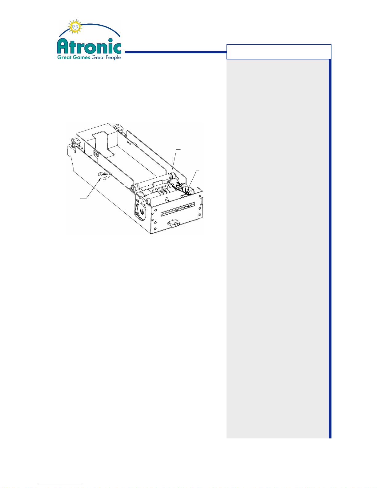
3. Remove the tear off band from the new paper stack
and place the paper stack into the ticket box.
The printable (blank) side has to face down.
(even if otherwise stated on the paper itself).
The top of form mark has to be on the leading
edge of the ticket, facing upwards.
4. Insert the leading ticket into the printer mechanism assembly's insertion guide area. When the
ticket is fed about 15 mm into the mechanism, the
printer automatically completes the feeding.
5. Slide the printer mechanism assembly back into
closed position, making sure that the assembly's
slide plungers snap into the racking retainers within the outer slide chassis.
6. The printer is ready for printing.
Top of form mark
OPERATING
Page 7
7
April 2005
Ticket Printer Ithaca
®
850
Cleaning the printer
Use a soft brush to clean paper dust from inside the
printer and chassis area. The paper dust should also
be removed from the sensor optics.
Cleaning the printer head
If streaking on the printed ticket is evident, the thermal print head may need to be cleaned. This can be
done by inserting a thermal printer cleaning card.
1. Remove remaining tickets from the ticket path and
check for any debris.
2. Press the green label to relatch the platen/cover
assembly, if it has been opened.
3. Make sure that there is power to the printer.
4. Unpack a 2.5" x 6" Thermal Cleaning Card and insert it into the feed path. The cleaning card will
automatically be drawn into the feed path.
5. Repeat the process if necessary.
6. Properly dispose of used cleaning card.
Top of form sensor
Ticket taken sensor
Paper low sensor
OPERATING
Page 8

8
April 2005
Ticket Printer Ithaca
®
850
Troubleshooting
Printer status LED / Bezel status
The Ithaca 850 printer features a LED indicator
system that provides the condition of the printer by
using a series of blinks to communicate the status of
the printer. If a bezel is installed, the status of the
bezel will be identical to the LED.
The following table lists the different LED indications.
Condition Status LED / Bezel
Unit ready On
Head up Medium blink
Door open Medium blink
Paper out Slow blink
Temperature error Fast blink
Paper jam 4 blinks - pause
RAM error 2 blinks - pause
Checksum error 5 blinks - pause
Feed button
LED Indicator
OPERATING
Page 9
9
April 2005
Ticket Printer Ithaca
®
850
Appendix
Electrical connections
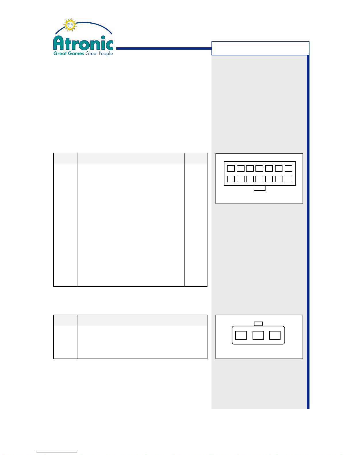
Power and communication are supplied through the
serial communications PCB located at rear of the
printer. The interface connector is a 14 pin Molex
Minifit Jr®.
The following table lists the pin connections.
Pin Function I/O
01 MRESET In
02 Not connected 03 +12 V DC In
04 Not connected 05 GND 06 +24 V DC 07 GND 08 +24 V DC 09 Bezel lamp / switched +24 V DC Out
10 GND 11 RS-232 RXD In
12 RS-232 TXD Out
13 DTR Out
14 RTS Out
Bezel lamp connector
Pin Function
01 Modulated +24 V DC
02 Not connected
03 GND
17
8
14
14 pin interface connector
Bezel lamp connector
3
12
APPENDIX
 Loading...