

Page 1

e-motion™ / Cashline™
Progressive Jackpot
How to setup a Progressive Jackpot
on Atronic slot machines
Including
- System Progressive
- Mikohn Progressive
- Atronic Progressive Link / APL™
- Cash Fever™
Rev. 2.0
www.atronic.comwww.atronic.com
www.atronic.comwww.atronic.com
www.atronic.com
January 2005
Page 2

2
January 2005
Progressive Jackpot
RELEASE INFO
e-motion™ / Cashline™
Progressive Jackpot
Rev. 2.0
Rel. January 2005
© 2003 - 2005 Atronic International GmbH. All rights reserved.
Page 3

3
January 2005
Progressive Jackpot
Introducing
• What is this manual about ........................................
• Jackpot Basics ......................................................
• How to setup - Basic Overview ..................................
• Which machines can be linked ....................................
Preparation
• A-link Config program versions ..................................
• Install A-link Config for Windows ................................
• Connecting PC for Jackpot configuration ....................
Setup Procedures
• Setting up a System Progressive
- Overview and requirements ..............................
- Link machines .................................................
- Prepare machines ...........................................
- Step-by-step Jackpot configuration ..................
• Setting up a Progressive Jackpot with a Mikohn Controller
- Overview and requirements ..............................
- Link machines .................................................
- Prepare machines ...........................................
- Step-by-step Jackpot configuration ..................
• Setting up an Atronic Progressive Link (APL)
- Overview and requirements ..............................
- Link machines ................................................
- APL Large Distance Link .................................
- Connect Overhead Display ...............................
- Prepare machines ...........................................
- Step-by-step APL Jackpot Configuration ...........
- APL Troubleshooting .................................................
• Setting up a Cash Fever™ Jackpot
- Overview and additional requirements ...............
- Link machines and connect Cash Fever™ PC .......
- Prepare machines ...........................................
- Step-by-step Cash Fever™ Jackpot Configuration
Atronic A-Link Configuration Program
• DOS version identifier and installation .......................
• A-Link Config for Windows - Menu structure ..............
Appendix
• Atronic Commboard 68K rev. 2.10
- Connectors .............................................................
- DIP Switch Overview for SAS protocol .....................
- DIP Switch Overview for GRIPS protocol ..................
- EPROM Naming .......................................................
• RAM Reset procedure - e-motion / Hi(!)bility ..............
• RAM Reset procedure - Cashline ..............................
4
5
6
7
8
9
9
11
11
12
13
17
18
19
20
24
25
26
26
27
28
31
32
33
34
36
37
41
42
51
52
53
54
55
56
CONTENT
Page 4
4
January 2005
Progressive Jackpot
What is this manual about
This document describes how to setup and configure
an Atronic gaming machine to participate in a linked
progressive Jackpot. It explains configuration of the
three most important progressive Jackpot types in a
detailed step-by-step guide.
This manual is intended to provide QUALIFIED
TECHNICAL PERSONNEL ONLY. Please read it carefully
before starting the Jackpot configuration.
Procedures described in this manual refer to both
Atronic Cashline™ machines using O-Level (STD)
software and Atronic e-motion™ / Hi(!)bility™ machines
using Q-Level (STD) software, if not otherwise stated.
Please note that USA software versions (P-Level) may
use different settings and procedures.
Information in this manual includes the most up-todate information available just before creation. All part
numbers and descriptions have been carefully reviewed
and checked for accuracy. All drawings and diagrams
contain the newest revisions released by Atronic. If
earlier revisions of diagrams or drawings are required,
please contact your Atronic Technical Services
representative.
Atronic International
Borsigstr. 26
32312 Luebbecke, Germany
(+49) 5741 273 720 FAX (+49) 5741 273 727
Atronic Americas
16537 N. 92nd Street
Scottsdale, Arizona 85260, USA
(+1) 480 922 0707 FAX (+1) 480 922 8877
Information in this document is subject to change without notice and does
not represent a commitment on the part of Atronic. No part of this
manual may be reproduced or transmitted in any form or by any means,
electronic or mechanical, including photocopying and recording, for any
purpose other than the purchaser’s personal use without written consent
of Atronic International. This document may contain trademarks of Atronic
International. All other brand or product names are trademarks or registred
trademarks of their respective companies.
© 2003 - 2005 Atronic International GmbH. All rights reserved.
INTRODUCING
Page 5

5
January 2005
Progressive Jackpot
Jackpot Basics
Jackpots are a common method for casinos to give
the probability of winning a large amount of money to
the player. To play a few credits on a jackpot machine
may come in for a win up to millions. Jackpots therefore
will attract more and different people to the casino.
Usually optical and acoustical appliances promote
jackpots. Large displays show current jackpot values
and/or attracting messages. In case of a jackpot win
displays or other optical attractors as well as sound
systems inform the casino’s visitors about the large
win. All those kinds of multi media events motivate
more people to play, and to play more.
Classical progressive jackpots are defined as a group
of slot machines contributing a certain percentage of
their turnover to a pot. Usually this pot is fed with a
base value at the start and after each win, called
jackpot hit. The pot then increments until a certain
winning combination appears on the slot machine. This
combination is said to „trigger the jackpot hit.“ Upon
a hit event the current jackpot amount is paid to the
player at the winning slot machine. Progressive games
can either be single machine jackpots called stand alone
jackpots or linked progressive jackpots, which consist
of several machines contributing to one jackpot.
All contributions taken from the slot machines’
turnover have to be contributed to people playing on
those slot machines. Therefore they can be considered
as additional payout of the slot machines. The basic
payout percentage is given by the applied paytable of
the machine. The additional payout generated by a progressive jackpot has to be considered in all calculation
where the slot machine’s theoretical payout is relevant.
Since the probability to win a jackpot has to be equal
for all slot machines participating in that jackpot, only
machines that match some link criteria, may be
connected to a linked progressive jackpot (see also
link criteria definition on page 7).
INTRODUCING
Page 6

6
January 2005
Progressive Jackpot
How to setup - Basic Overview
This chapter describes the basic principles to plan,
setup, and configure a Progressive Jackpot.
1. Determine which machines are to be linked.
2. Check pre-requirements.
• Does the game software support progressives?
• Is new Paytable software necessary to adjust
overall Return To Player Percentage (RTP)?
• Does the Commboard software support progressives and matches to the Casino's online system?
• Is a security chip with progressive support installed?
• Does the game software comply with the 4 important link criteria? (described on next page)
• Which configuration software version is needed?
• Is additional hardware (such as cables or adapters) needed?
3. Order needed parts.
• A-Link Setup Kit (for Jackpot configuration).
• Security Chips with progressive support.
• A-Link Cables and Power supply Adapter (for APL
or Mikohn progressives)
• Are there parts from other vendors needed?
e.g. SMIBs or network equipment?
4. Prepare external PC for Jackpot Configuration.
5. Prepare gaming machines for Jackpot Configuration.
6. Link machines.
7. Jackpot Configuration with "A-Link Config" software.
8. Configure external Controller (if applicable).
9. Test the Progressive.
Note:
Please contact Atronic
Technical Service, if you are
planning to setup up a Progressive Jackpot. Our team will give
you best support in planning
and realisation.
INTRODUCING
Page 7

7
January 2005
Progressive Jackpot
Which machines can be linked
The 4 important link criteria
In order to mix different game themes in a bank of
progressive machines, following important criteria must
be met. All machines in the bank must have:
• The same denomination
• The same top award hit frequency
(given in pulls to hit)
• The same top award
• The same Jackpot trigger
(achievable playing MAX BET
or MAX BET PER LINE)
The machines also should have Paytable-software with
the same Return to Player Percentage (RTP), even if
this is not relevant for the Jackpot itself.
Game software versions
Please contact Atronic to find out which game versions are suitable for your Progressive Jackpot project.
Commboard software versions
Participating in a Progressive Jackpot environment the
Commboard software has to match to the casino's
online system and to the Atronic game software.
This manual refers to Q-Level software (for e-motion/
Hi(!)bility) and to current O-Level software (for
Cashline). Earlier O-Level software may require different settings. See "Commboard 68K - EPROM Naming"
on page 54 for details or contact Atronic to find out
which Commboard software version is suitable for your
Progressive Jackpot project.
Security Chip / Security Device
Each Atronic machine participating in a Progressive
Jackpot, has to be equipped with a security chip with
progressive support. This chip has to be mounted to
Masterboard socket U35 (for Cashline) or U22 (for emotion/Hi(!)bility).
INTRODUCING
Page 8

8
January 2005
Progressive Jackpot
Preparing PC for configuration
Which version of A-Link Config to use
Jackpot configuration can either be carried out with
Alink Config for Windows or with one of the DOS program versions. Alink Config for Windows covers all
recent configuration versions in one application. ALink
Config DOS versions are specific programms for one
particular configuration version.
As most PCs use Windows® operating systems,
procedures described in this manual refers to Alink
Config for Windows.
How to find the appropriate A-Link for DOS version
1. Jackpot Configuration Menu
1. Open Main Door and press Service Button to enter
Service Menu.
2. Enter "Jackpot Configuration" menu.
• For Atronic Cashline series:
Select "PC-Setup / Jackpot Configuration".
• For Atronic Hi(!)bility / e-motion series:
Select folder "Settings / Jackpot Configuration"
3. When all pre-requirements are fulfilled, the appropriate A-Link Config software version is displayed
on screen.
Example: "Use Setup Version 08" stands for the
DOS version with the identifier "08". You have to
use AC08xx.exe.
2. Commboard EPROM Naming
The A-Link version can also be identified by the Comm
board software naming. The third last and the second
last digit represents the version identifier.
See Appedix "Commboard 68K - EPROM Naming
Scheme" on page 54 for details.
Note (for Cashline only): Do
not confuse the A-Link Config
version with the PC-Setup program version which is displayed
in the lower left corner.
Note:
If using A-Link Config for
Windows, it is not necessary
to figure out the setup version.
Note:
If you are using Windows XP
®
or Windows 2000®, please use
A-Link Config for Windows 2.0
or higher.
Use A-Link Config for Windows
2.1 or higher for Cash Fever™
Jackpot Configuration.
PREPARATION
Page 9
9
January 2005
Progressive Jackpot
Connecting PC to Atronic gaming machine
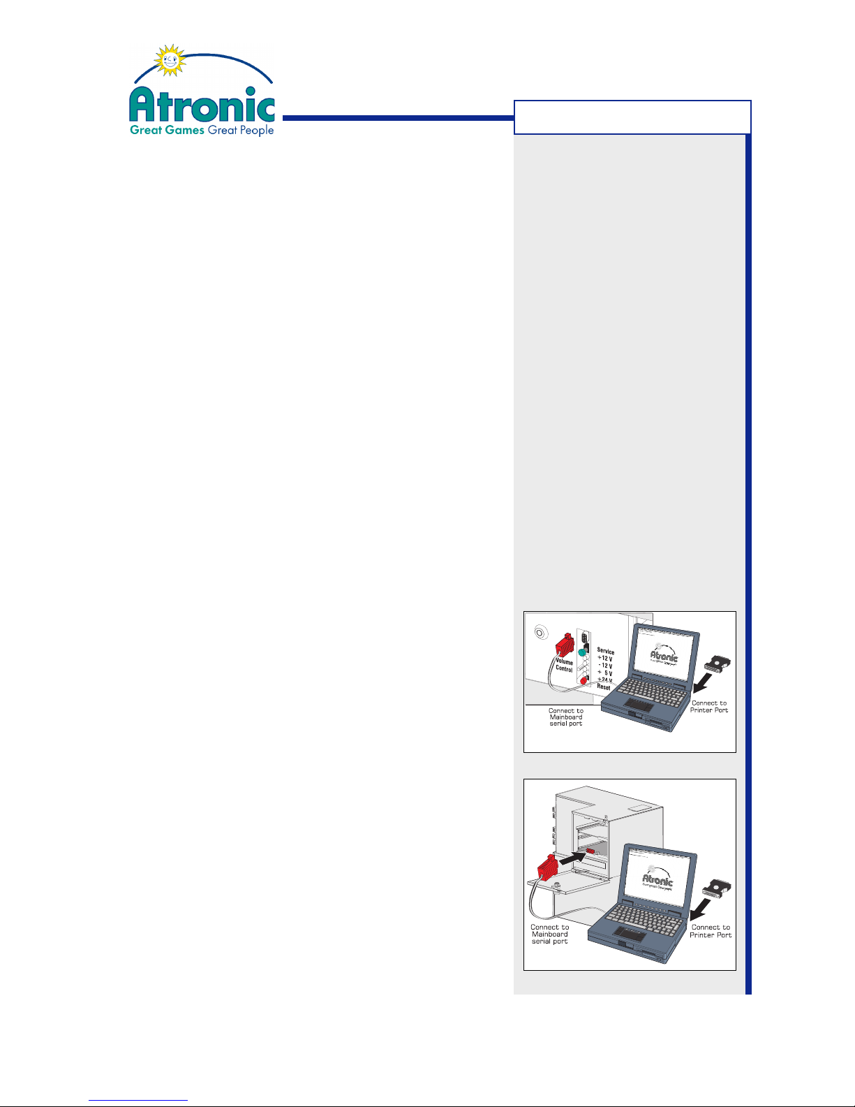
1. Connect Hardlock Dongle (type 0300) to PC's printer port (LPT), with the PC switched off.
2. Start the PC and run "A-Link Config for Windows".
3. Connect the PC Setup Cable to the PC's serial interface (COM1) and to the gaming machine's serial
interface (Mainboard J2).
At e-motion™ machines the logic box must be open
to get access to the serial interface.
4. Carry out Jackpot configuration as described in respective setup procedures.
Preparing PC for configuration
Installing Alink Config for Windows
Alink Config for Windows requires installation of a
Hardlock Dongle driver. This Hardlock Dongle is required
to unlock the program and has to be connected to the
PC's printer port (LPT) when using the program.
1. Connect Hardlock Dongle to PC's printer port (LPT),
with the PC switched off.
2.Copy the two files "dongle_install.exe" and
"Alink_Setup.exe" from floppy disk to a temporary
folder on the PC's harddisk.
3. Run "dongle_install.exe" to install the Hardlock Dongle
drivers and follow instructions on screen.
4. Reboot PC to initialize drivers.
5.Install Alink config for Windows by running
"Alink_Setup.exe" and follow instructions on screen.
6. Double click the Alink Config icon on the desktop to
start the program.
e-motion™ / Hi(!)bility™ series
Cashline™ series
Note:
The Hardlock Dongle (Type
0300) is part of the A-Link Setup Kit, obtainable from Atronic.
PREPARATION
Page 10

10
January 2005
Progressive Jackpot
Setting up a
System Progressive Jackpot
SYSTEM PROGRESSIVE
Page 11

11
January 2005
Progressive Jackpot
Setting up a System Progressive Jackpot
Overview
In a linked System Progressive Jackpot all participating
machines are connected to the Accounting Host System. Data communication is carried out via a Slot
Machine Interface Board (SMIB), a Machine Data
Controller (MDC) or a similar device, which is connected
to the Atronic Commboard 68k. The Jackpot is
controlled by Jackpot features of the Accounting Host
System or by a dedicated Jackpot controller.
Requirements
• Commboard 68k with a software version according
to the accounting system protocol (e.g. SAS 5.x).
• A progressive version security chip.
• Atronic PC-Setup cable.
• Software "Atronic Alink Config for Windows" (or appropriate DOS version) with Dongle 300.
Link machines
The Commboard has to be connected to a Machine
Data Controller (MDC) or a similar device that connects
to the floor network. Depending on connected device,
online protocol and different system features, there
are several ways to connect to the Commboard. Please
refer to "Commboard 68k Rev. 2.10 Connectors
Overview" on page 51 or ask Atronic Technical Service.
Note: Please contact Atronic
Technical Service to get
information, if your machine
setup is suitable for a System
Progressive Jackpot.
SYSTEM PROGRESSIVE
Page 12
12
January 2005
Progressive Jackpot
Setting up a System Progressive Jackpot
(Continued)
Prepare machines
The following procedure has to be carried out on every
Atronic machine participating in the link.
1. Check if all pre-requirements are fulfilled
2. Set the machines accounting system address. Each
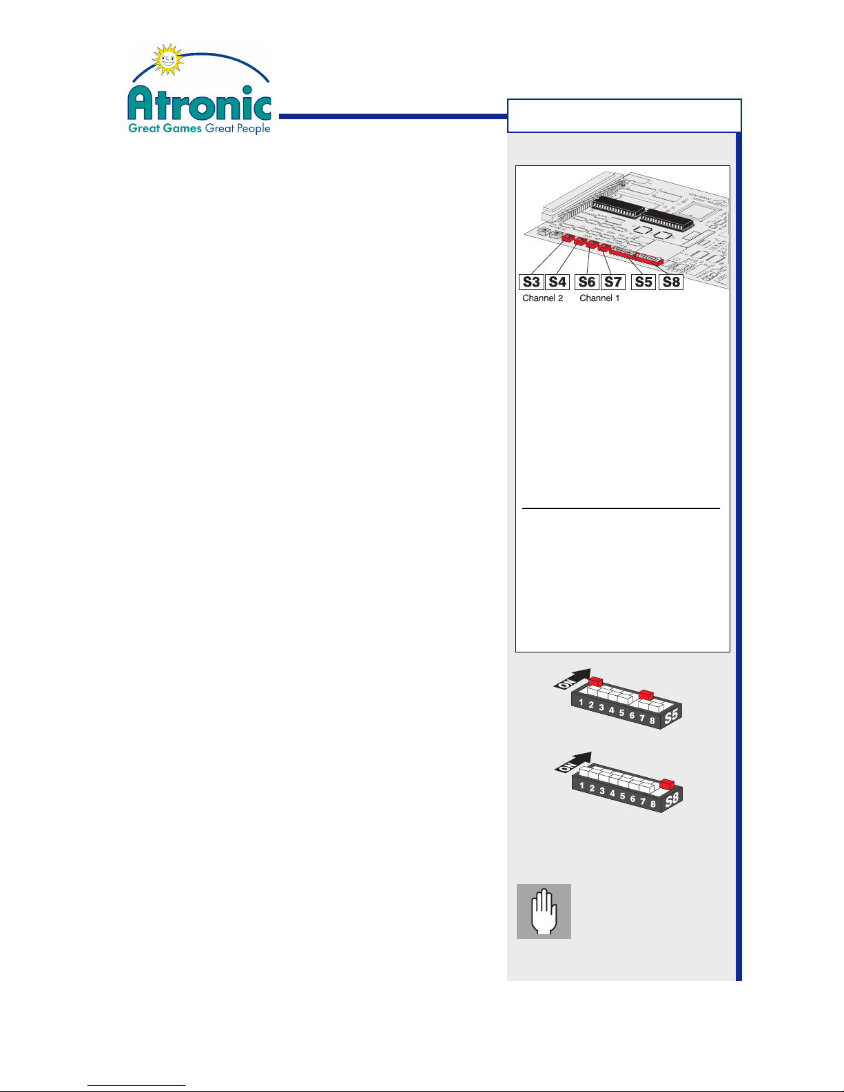
machine in the link must have a unique address.
• SAS protocol
Set address for channel 1 with switch S6 and S7.
Set address for channel 2 with switch S3 and S4.
Selecting an address other than 00 activates channel. Address 00 disables channel.
• GRIPS protocol
Set address with switch S6 and S7.
Set adresses >99 with S3 and S4, if necessary.
3.
For dual channel mode with SAS protocol only
:
Allocate communication functions to channel 1 or
channel 2 with DIP-switches S8 / 2 - 6.
See table "DIP-Switch S8" on pages 52-53 for details.
4. Set DIP switch S5 / 1 to ON
and DIP switch S5 / 2 and S5 / 3 to OFF.
to enable (accounting) system progressive mode.
5. Set DIP switch S5 / 6 to ON
to enable accounting system communication.
6. (optional) Aditionally set DIP switch S8 / 8 to ON
to enable a machine lock, in case of a loss of communication to the accounting system.
7. Carry out a RAM Reset on Main- and Commboard.
(described on pages 55-56 or in manual "Software").
8. Carry out Initial Setup. Necessary settings are:
• Set a Progressive Group (other than #00)
• Set "Commboard required" to YES
9. Link machines (connect SMIB or similar device).
10.Carry out Jackpot configuration (next page).
accounting system address
Comm software using
SAS protocol
Address on channel 1
S6: x10
S7: x1
Address on channel 2
S3: x10
S4: x1
Comm software using
GRIPS protocol
Address
S3: x100
S4: x1000
S6: x10
S7: x1
optional
Important: Do not
start any games or
insert credits after
RAM reset, until Jackpot
configuration is finished.
SYSTEM PROGRESSIVE
Page 13
13
January 2005
Progressive Jackpot
Setting up a System Progressive Jackpot
(Continued)
Jackpot configuration has to be carried out on every
machine in the link. Settings made at the first machine
can be saved to disk to configure further machines.
Jackpot Configuration (first machine)
1. Prepare and connect PC (as described on page 8)
and start "A-Link Config" program.
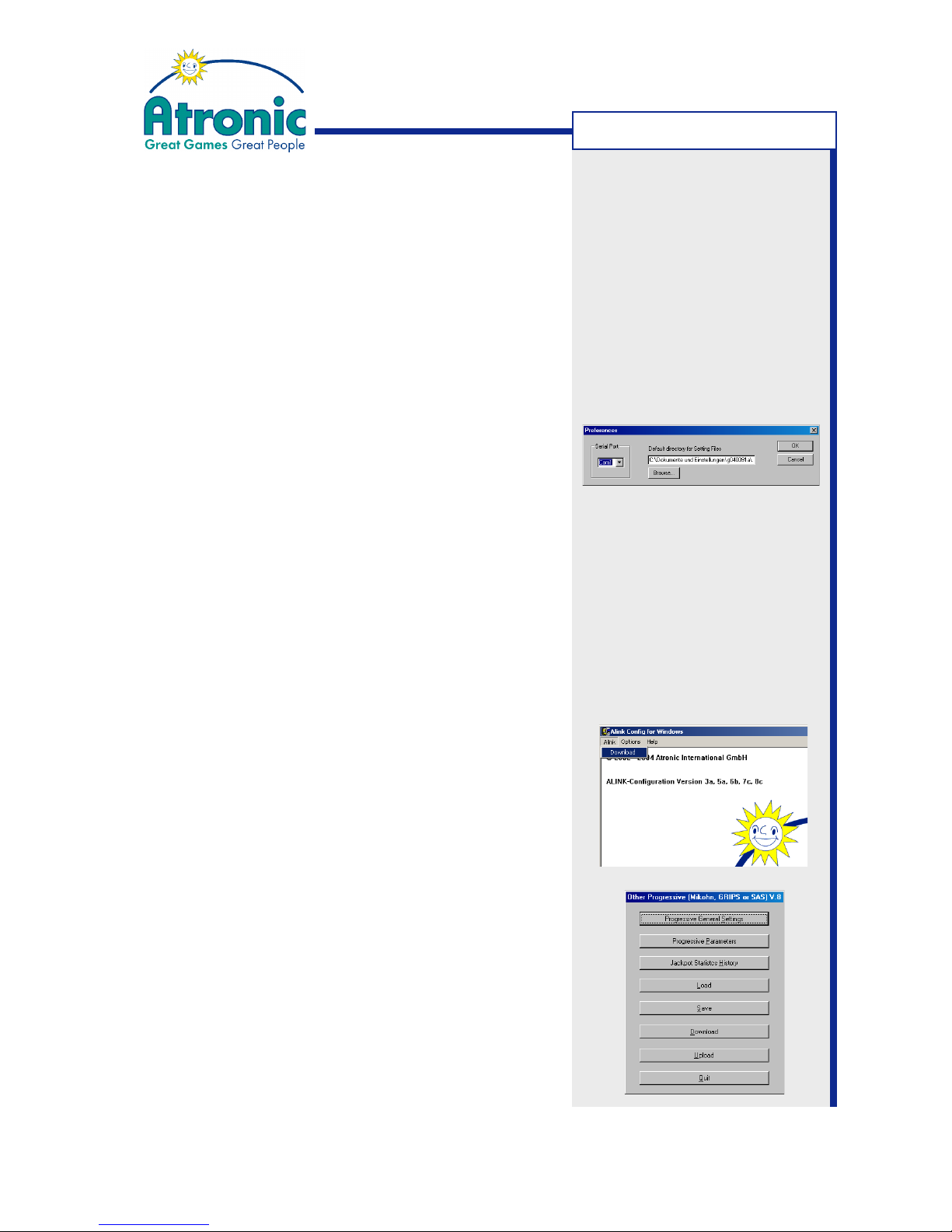
2. Select menu "Options" and click on "Preferences".
• Select the COM port where the PC-Setup cable
is connected to (default is COM1).
• Select a default directory to save setting files.
Confirm with "OK".
3. Download current Jackpot configuration.
• For Atronic Cashline series:
Enter Service Menu and select "PC-Setup/Jackpot Configuration" and press center lit button
on the button panel.
• For Atronic Hi(!)bility / e-motion series:
Enter Service Menu and select "Settings/Jackpot Configuration" and press "Start Configurati-
on" button on the touch screen.
Select menu "Alink" on the PC and click on "Down-
load".
Cashline only
: Download has to be started simultaneous at PC and machine within a few seconds
to prevent a "Communication time out" error.
When download of current Jackpot Configuration
data was successful, the "Other Progressives"
menu is shown on screen.
SYSTEM PROGRESSIVE
Page 14
14
January 2005
Progressive Jackpot
Setting up a System Progressive Jackpot
(Continued)
Jackpot Configuration (first machine) (Continued)
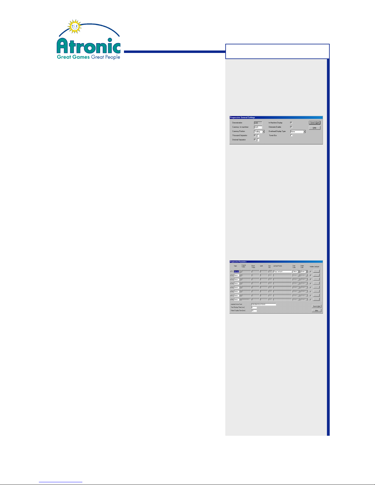
4. Select "Progressive General Settings".
5. Enable and configure "In Machine Display".
This will add an additional window to the game
screen showing the current Jackpot value.
Additional settings for in-machine display:
Currency Enter a 3 digit ASCII string, which is
displayed trailing or leading the JP value
Currency Position Position of the currency string
Thousand Separator Enter "," or "."
Decimal Separator Enter "," or "."
Odometer Enables a smooth counting of the JP value
6. Choose "Overhead Display Type", if a display is connected to P7 on the Commboard.
7. Confirm settings with "Save & Quit".
8. Select "Progressive Parameters".
9. Set "Type" of JP 1 to NORMAL, to enable a progressive Jackpot.
Do not activate JP 2 to JP 8. These additional
Jackpot levels are reserved for Multi Level Jackpot systems such as Cashfever™ or Towerline™.
10.Edit "Jackpot Name", "Text Color" and "Value Color".
Jackpot Name Is displayed alternating with the JP value on
the in-machine display
Text color Color of the "Jackpot Name" text
Value color Color of the displayed Jackpot value.
11.Type in "Jackpot Won Text" and edit "Text Display
Time" and "Value Display Time", if needed.
Jackpot Won Text This text is displayed upon a Jackpot hit
Text Display Time Timespan in sec. the "Jackpot Name" text
is displayed
Value Display Time Timespan in sec. the JP value is displayed.
12.Confirm settings with "Save & Quit".
Note: Do not enable the "Tower
Box" feature, unless you
configure a Towerline™ machine!
Note: Currency strings "EUR"
and "GBP" are interpreted by
the software and will display "¤"
respective "£" symbol.
Note: "Jackpot Name" and
"Jackpot Won Text" supports
max. 16 characters. Use only
english alphabet. Country
specific characters (such as "ö"
or " é") are not displayed.
SYSTEM PROGRESSIVE
Page 15
15
January 2005
Progressive Jackpot
Setting up a System Progressive Jackpot
(Continued)
Jackpot Configuration (first machine) (Continued)
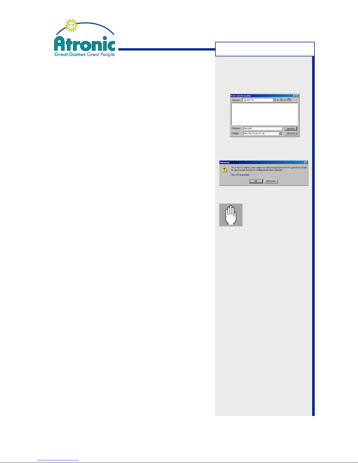
13.Check all settings carefully and select "Save" to
save settings to disk. Saved Jackpot Configuration settings can later be loaded into the program
to configure further machines.
14.Select "Upload" to send data to the machine.
15. Pay attention to application notes and confirm with
"OK" to start upload.
• For Atronic Cashline series:
Press center lit button to start upload.
16.When upload was successful, exit "Jackpot Configuration" menu, remove PC Setup Cable and close
Logic Box (e-motion only) and Main Door.
17.
e-motion machines only:
Clear "Logic Door Open" message via Audit Key.
Jackpot Configuration (further machines)
(Brief description)
1. Connect PC and Atronic machine.
2. Download current Jackpot configuration.
3. Load previous saved Jackpot configuration settings
into the program.
4. Select "Upload" to upload configuration data to the
machine.
5. Confirm application notes with "OK" to start upload.
• For Atronic Cashline series:
Press center lit button to start upload.
6. When upload was successful, continue with next
machine.
Important:
Check all settings
carefully before
uploading. Any subsequent modification of "Progressive Parameters" needs a RAM
reset on Main- and
Commboard!
SYSTEM PROGRESSIVE
Page 16

16
January 2005
Progressive Jackpot
Setting up a Progressive Jackpot
using a Mikohn controller
MIKOHN PROGRESSIVE
Page 17

17
January 2005
Progressive Jackpot
Please contact the Atronic
Technical Service to obtain the
latest version of the A-Link
Setup Kit, according to your
needs.
Additional parts:
A-Link cable, 5m
P/N: 65001250
Power supply adapter
WEB - 2xWEB
P/N: 65022845
Setting up a Progressive Jackpot using a
Mikohn Controller
This section describes how to setup a progressive
Jackpot using an external Mikohn controller running
protocol versions MS 10 Progressive, MS 27 Mystery
or MS 27 Mystery & Progressive,
Overview
If using an external Jackpot controller such as the
Mikohn Super Controller or the Mikohn DCU, the Jackpot is controlled by this device.
Data communication is carried out via RS485 half
duplex bus interface (which is implemented to Atronic's
Commboard 68k) using A-link™ wiring.
Requirements
• An Atronic Commboard 68k with a software that
supports Mikohn MS10 and MS27, for every machine in the link.
• A progressive version security chip, for every machine in the link.
• One A-Link cable, for every machine in the link plus
one A-Link cable that connects to the controller.
• A power supply adapter, if more than 16 machines
are to be linked.
• The Atronic A-Link Setup Kit.
The standard A-Link Setup Kit contains:
• Power supply
• 230V main cable
• PC Setup cable
• Overhead display cable
• Hardlock Dongle 0300 G/E
• Dongle drivers
• A-Link Config software
• APL manual.
MIKOHN PROGRESSIVE
Page 18
18
January 2005
Progressive Jackpot
Setting up a Progressive Jackpot using a
Mikohn Controller
Link machines
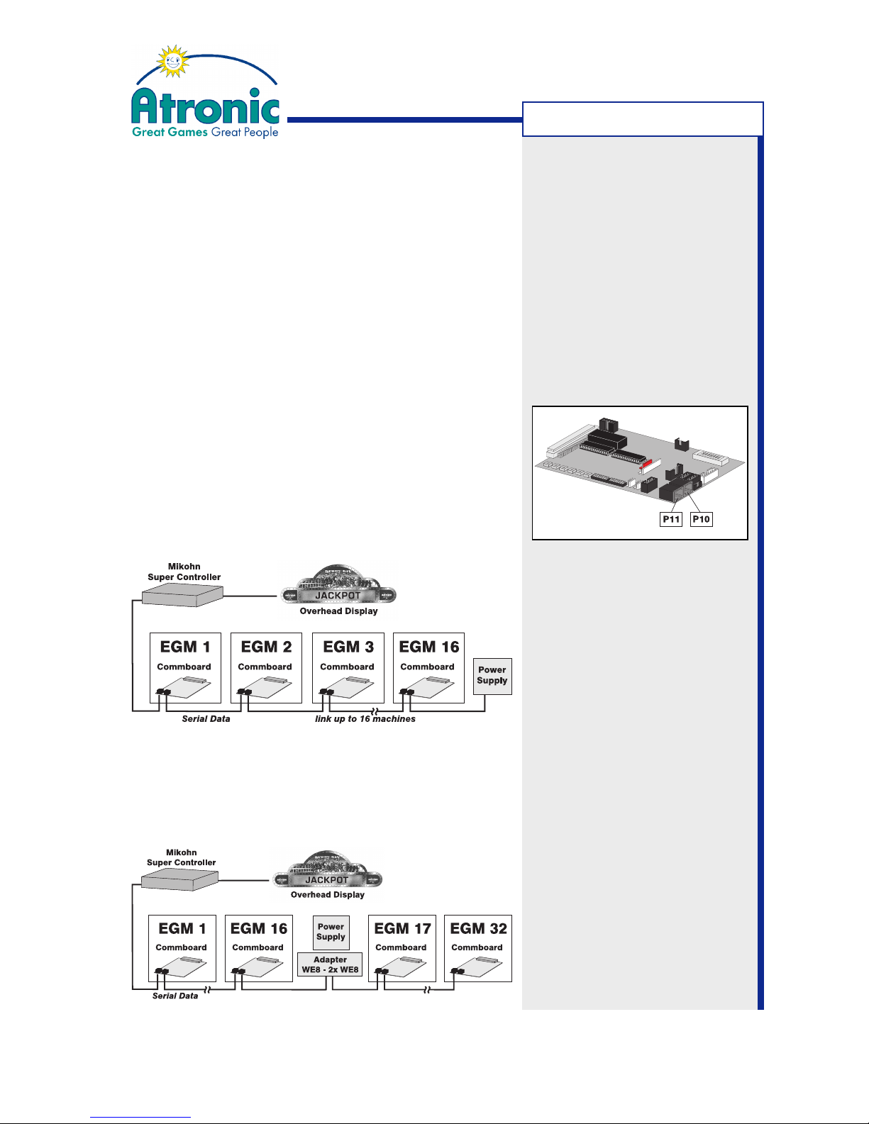
Using the MS 10 progressive protocol the Mikohn
Super Controller can drive up to 32 EGMs in one
Jackpot link.
The Mikohn DCU Controller using MS 27 protocoll
can drive 3 different link lines with up to 32 EGMs on
each link line.
Machines are linked using A-Link™ wiring connected to
P10 and P11 on the Commboard. P10 and P11 (RJ45 Connectors) are parallel connected, so it does not
matter which one is used.
If less than 16 machines are linked, the Power Supply
Unit can be connected at the end of the link.
If more than 16 machines are linked (max. 32), the
Power Supply Unit has to be connected in the middle
of the link, using the "Power Supply Adapter WEB 2xWEB ALINK" (P/N: 65022845).
MIKOHN PROGRESSIVE
Page 19
19
January 2005
Progressive Jackpot
Setting up a Progressive Jackpot using a
Mikohn Controller
Prepare machines
Following procedure has to be carried out on every
Atronic machine participating in the link.
1. Check if all pre-requirements are fulfilled.
2. Set machines progressive system address with
rotary-switches S1 and S2 on the Commboard. Each
machine in the link must have a unique address from
"01" to "32". Address "00" is not valid.
S1: x10
S2: x 1
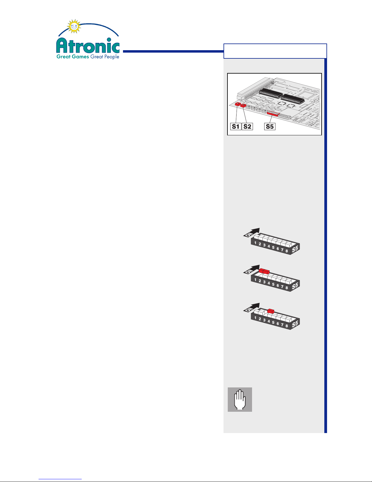
3. Set one operation mode.
For Mikohn MS 10:
Set DIP switch S5 / 1 - 3 to OFF
For Mikohn MS 27 Mystery:
Set DIP switch S5 / 1 - 2 to ON
Set DIP switch S5 / 3 to OFF
For Mikohn MS 27 Mystery and Progressive:
Set DIP switch S5 / 1 - 2 to OFF
Set DIP switch S5 / 3 to ON
4. Carry out a RAM Reset on Main- and Commboard.
(described on page 51-52 and in manual "Software").
5. Carry out Initial Setup. Necessary settings are:
• Set Progressive Group to #00 (No group)
• Set "Commboard required" to YES
6. Link machines using Atronic A-link™ wiring.
7. Carry out Jackpot configuration.
(as described on next page)
Example: Address 24 =
S1 to 2 and S2 to 4
MS 10
MS 27 Mystery
and Progressive
MS 27 Mystery
Important: Do not
start any games or
insert credits after
RAM reset, until Jackpot
configuration is finished.
MIKOHN PROGRESSIVE
Page 20
20
January 2005
Progressive Jackpot
Setting up a Progressive Jackpot using a
Mikohn Controller
Jackpot configuration has to be carried out on every
machine in the link. Settings made at the first machine
can be saved to disk to configure further machines.
Jackpot Configuration (first machine)
1. Prepare and connect PC or Laptop, (as described
on page 9) and start "A-Link Config" program.
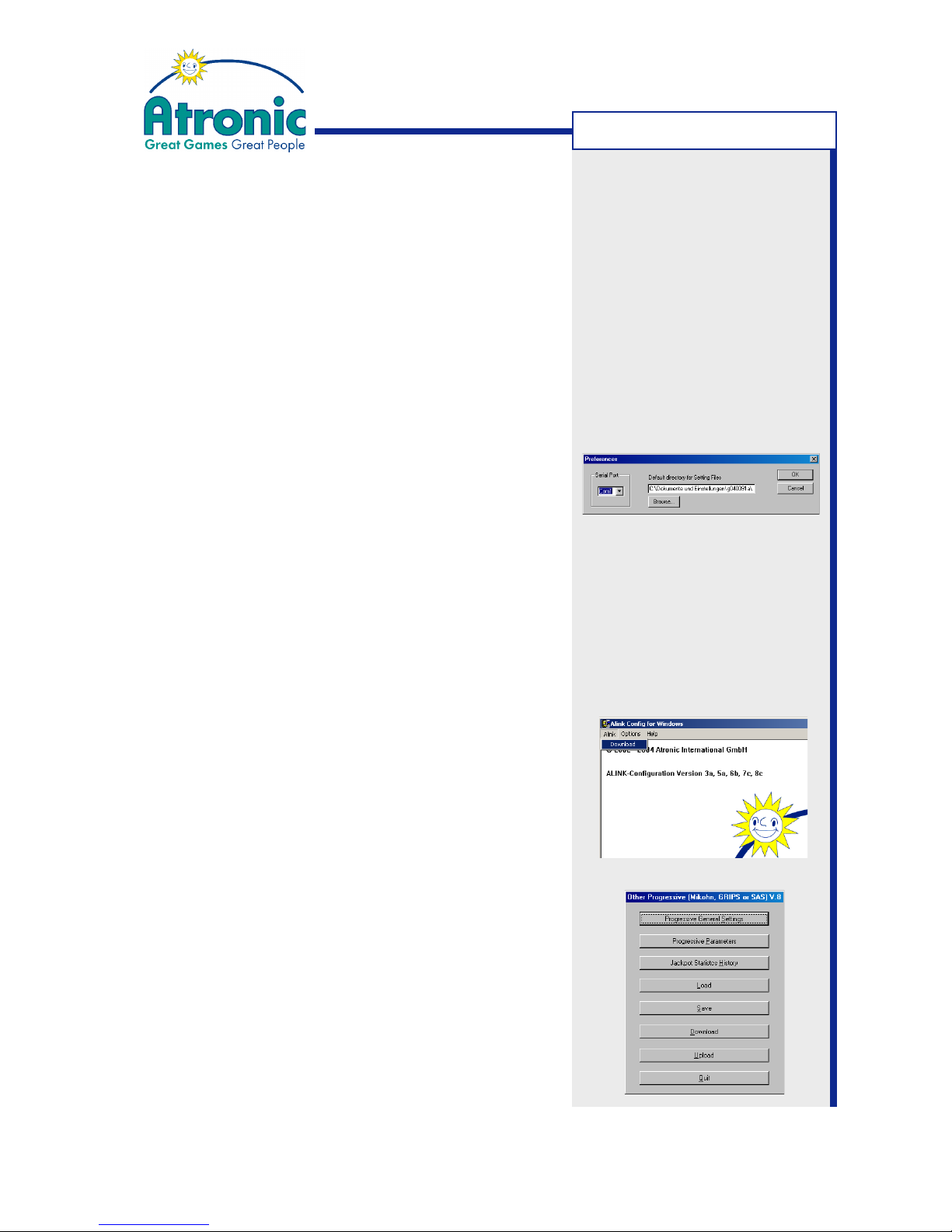
2. Select menu "Options" and click on "Preferences".
• Select the COM port where the PC-Setup cable
is connected to (default is COM1).
• Select a default directory to save setting files.
Confirm with "OK".
3. Download current Jackpot configuration.
• For Atronic Cashline series:
Enter Service Menu and select "PC-Setup/Jackpot Configuration" and press center lit button
on the button panel.
• For Atronic Hi(!)bility / e-motion series:
Enter Service Menu and select "Settings/Jackpot Configuration" and press "Start Configurati-
on" button on the touch screen.
Select menu "Alink" on the PC and click on "Down-
load".
Cashline only
: Download has to be started simultaneous at PC and machine within a few seconds
to prevent a "Communication time out" error.
When download of current Jackpot Configuration
data was successful, the "Other Progressives"
menu is shown on screen.
MIKOHN PROGRESSIVE
Page 21

21
January 2005
Progressive Jackpot
Setting up a Progressive Jackpot using a
Mikohn Controller
(Continued)
Jackpot Configuration (first machine) (Continued)
4. Select "Progressive General Settings".
5. Enable and configure "In Machine Display".
This will add an additional window to the game
screen showing the current Jackpot amount.
Additional settings for in-machine display:
Currency Enter a 3 digit ASCII string, which is
displayed trailing or leading the JP value
Currency Position Position of the currency string
Thousand Separator Enter "," or "."
Decimal Separator Enter "," or "."
Odometer Enables a smooth counting of the JP value
6. Choose "Overhead Display Type", if a display is connected to P7 on the Commboard.
7. Confirm settings with "Save & Quit".
8. Select "Progressive Parameters".
9. Set "Type" of JP 1 to NORMAL, to enable a progressive Jackpot.
Do not activate JP 2 to JP 8. These additional
Jackpot levels are reserved for Multi Level Jackpot systems such as Cashfever™ or Towerline™.
10.Edit "Jackpot Name", "Text Color" and "Value Color".
Jackpot Name Is displayed alternating with the JP value on
the in-machine display
Text color Color of the "Jackpot Name" text
Value color Color of the displayed Jackpot value
11.Type in the "Jackpot Won Text" and edit "Text Display Time" and "Value Display Time", if needed.
Jackpot Won Text This text is displayed upon Jackpot hit
Text Display Time Timespan in sec. the "Jackpot Name" text
is displayed
Value Display Time Timespan in sec. the JP value is displayed.
12.Confirm settings with "Save & Quit".
Note: Currency strings "EUR"
and "GBP" are interpreted by
the software and will display "¤"
respective "£" symbol.
Note: Do not enable the "Tower
Box" feature, unless you
configure a Towerline™ machine!
Note: "Jackpot Name" and
"Jackpot Won Text" supports
max. 16 characters. Use only
english alphabet. Country
specific characters (such as "ö"
or " é") are not displayed.
MIKOHN PROGRESSIVE
Page 22
22
January 2005
Progressive Jackpot
Setting up a Progressive Jackpot using a
Mikohn Controller
(Continued)
Jackpot Configuration (first machine) (Continued)
13.Check all settings carefully and select "Save" to
save settings to disk. Saved Jackpot Configuration settings can later be loaded into the program
to configure further machines.
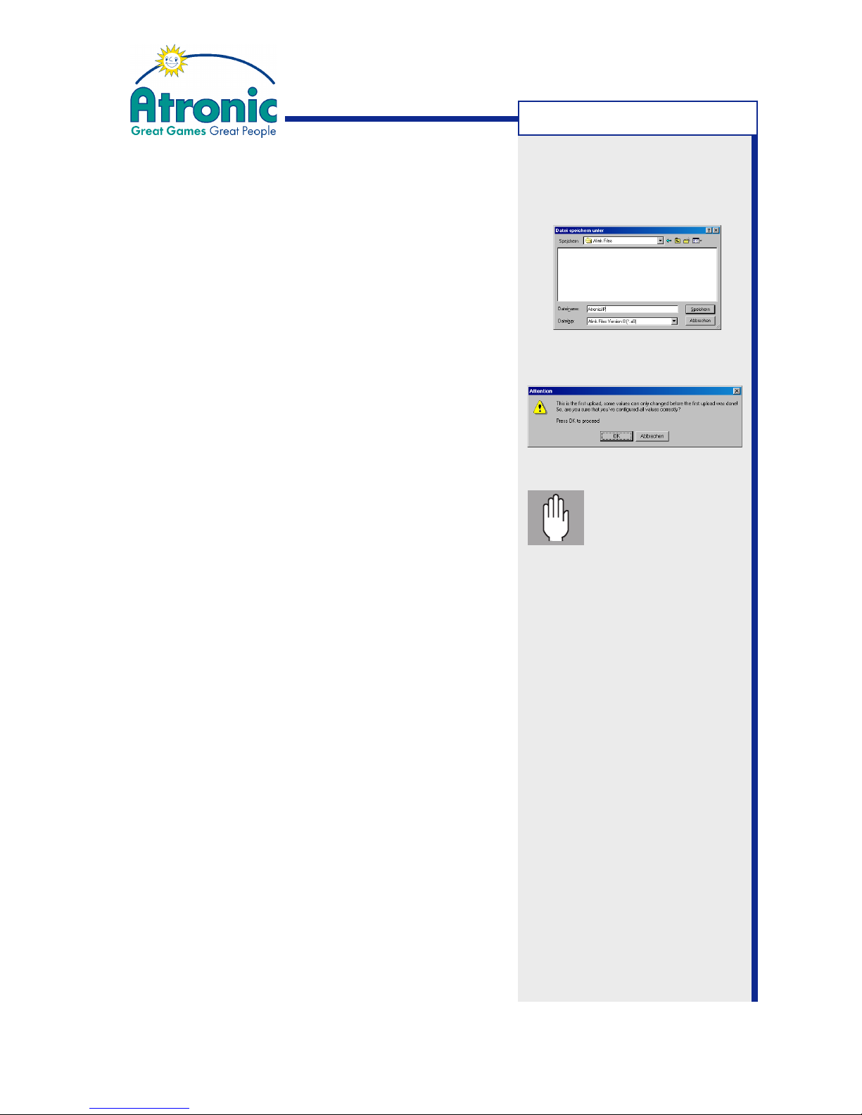
14.Select "Upload" to send data to the machine.
15.Pay attention to the application notes and confirm
with "OK" to start upload.
• For Atronic Cashline series:
Press center lit button to start upload.
16.When upload was successful, exit "Jackpot Configuration" menu, remove PC Setup Cable and close
Logic Box (e-motion only) and Main Door.
17.
e-motion machines only
Clear "Logic Door Open" message via Audit Key.
Jackpot Configuration (further machines)
(Brief description)
1. Connect PC and Atronic machine.
2. Download current Jackpot configuration.
3. Load the previous saved Jackpot Configuration
settings into the program.
4. Select "Upload" to upload configuration data to the
machine.
5. Confirm application notes with "OK" to start upload.
• For Atronic Cashline series:
Press center lit button to start upload.
6. When upload was successful, continue with next
machine.
Important:
Check all settings
carefully before
uploading. Any subsequent modification of "Progressive Parameters" needs a RAM
reset on Main- and
Commboard!
MIKOHN PROGRESSIVE
Page 23

23
January 2005
Progressive Jackpot
Setting up an
Atronic Progressive Link / APL™
APL
Page 24

24
January 2005
Progressive Jackpot
Setting up an Atronic Progressive Link
Overview
In an Atronic Progressive Link (APL) the participating
machines are operating without external controller
hardware. The APL Master machine controls the
Jackpot. Data communication is carried out via RS485
half duplex bus interface, which is implemented to the
Atronic Commboard (A-Link™ wiring).
In an APL one commboard is the dedicated progressive jackpot controller (Master). Jackpot configuration data is stored on all commboards allowing to
change the master machine any time.
Requirements
• An Atronic Commboard 68k with a software that
supports APL, for every machine in the link.
• A progressive version security chip, for every machine in the link.
• One A-Link™ cable, for every machine in the link.
• A power supply adapter, if more than 16 machines
are to be linked.
• Atronic A-Link™ Setup Kit.
The A-Link™ Setup Kit contains:
• Power supply 230V or 115V
• Mains cable
• PC Setup cable
• Overhead display cable
• Hardlock Dongle 0300 G/E
• Dongle drivers
• A-Link Config software
• APL manual
Please contact Atronic
Technical Service to obtain
appropriate A-Link Setup Kit.
Additional parts:
A-Link cable, 5m
p/n: 65001250
Power supply adapter
1x WE8 to 2x WE8
p/n: 65022845
APL
Page 25
25
January 2005
Progressive Jackpot
Setting up an Atronic Progressive Link
Link machines
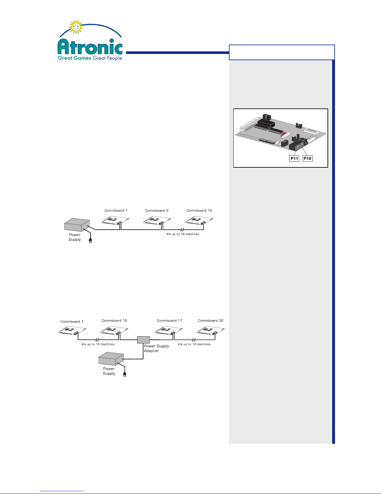
In an Atronic Progressive Link (APL) machines are linked
using Atronic A-Link™ cables connected to P10 and
P11 on the Commboard. P10 and P11 (RJ-45
Connectors) are wired parallel, so it does not matter
which one is used. The end of the link is automatically
terminated by the Commboard.
Link up to 16 machines
If less than 16 machines are linked, the Power Supply
Unit can be connected at either end of the link.
Link 16 - 32 machines
If more than 16 machines are linked (max. 32), the
Power Supply Unit has to be connected in the middle
of the link, using the "Power Supply Adapter WEB 2xWEB ALINK" (P/N: 65022845).
APL
Page 26
26
January 2005
Progressive Jackpot
Power
Supply
Commboard 1 Commboard 2 Commboard n
Power
Supply
Commboard 1 Commboard 2 Commboard n
Earth-Print
Board
Earth-Print
Board
CAT-7 cable, up to 700 meters
Bank 1
Bank 2
Setting up an Atronic Progressive Link
APL Large Distance Link
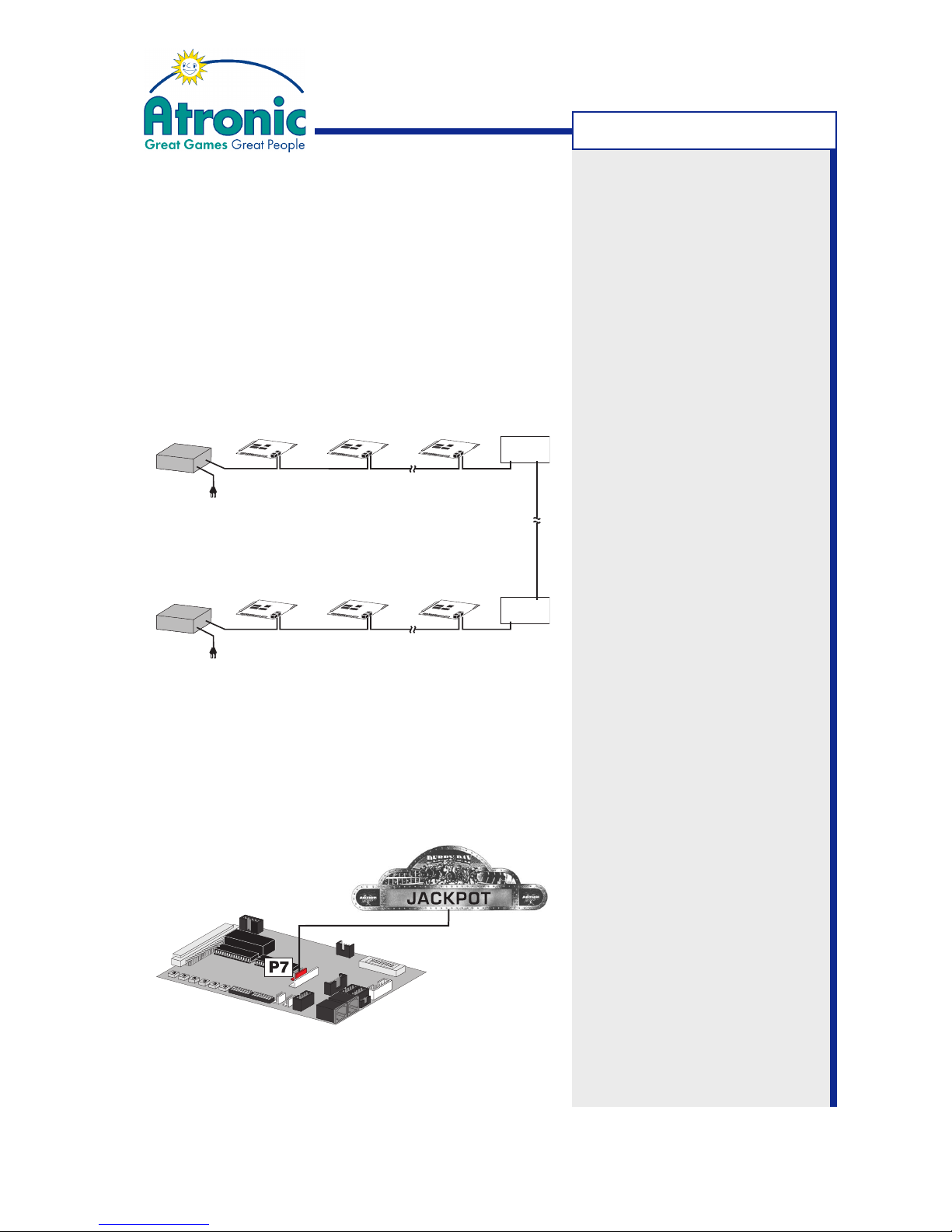
Using the (optional) Atronic "Earth-Print" board and a
CAT-7 network cable, machines can be linked over larger
distances. Two banks of machines can be linked over a
distance of up to 700 meters. Linking 3 banks, the
maximum length between the banks is 500 meters.
Linking 4 banks, the maximum length is 300 meters.
Schematic diagram
Connect Overhead Display (optional)
Connect Overhead Display Cable to P7 on any
Commboard participating in the A-Link. Set matching
"Overhead Display Type" by means of A-Link Config
software.
Cables needed for an APL
Large Distance Link:
Cable from Commboard to
Commboard:
A-Link cable, 5m
P/N: 65001250
Cable from Power Supply to
Commbard:
Alink RJ45 12V / GND, 1.5m
P/N: 6503 3078
Cable from Commboard to
Earth-Print board:
Alink RJ45 without 12 V
P/N: 6503 2570
APL
Page 27
27
January 2005
Progressive Jackpot
Setting up an Atronic Progressive Link
Prepare machines
Following procedure has to be carried out on every
Atronic machine participating in the link (except step
4 and step 8).
1. Check if all pre-requirements are fulfilled.
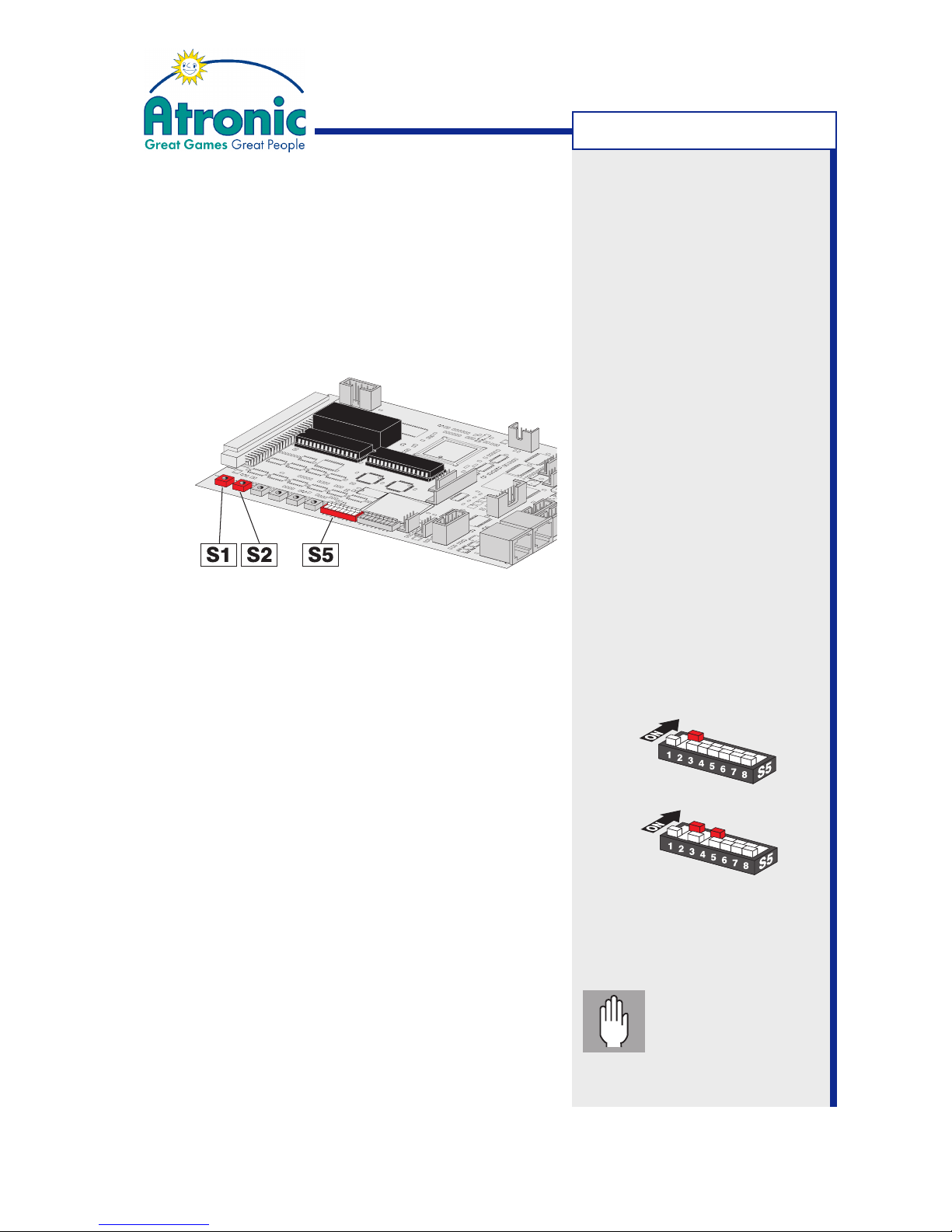
2. Set machines Progressive System Address with
rotary switches S1 and S2 on the commboard. Each
machine in the link must have a unique address from
"01" to "32". Address "00" is not valid.
S1: x10
S2: x 1
3. Activate APL mode on all linked machines.
Set Commboard switch S5 / 2 to ON.
Set switch S5 / 1, S5 / 3 and S5 / 4 to OFF.
4. Define one machine as Master by setting Com-
mboard switch S5 / 4 to ON. This activates
implemented Jackpot controller functions.
5. Carry out a RAM Reset on Main- and Commboard.
(described on page 51-52 and in manual "Software").
6. Carry out Initial Setup. Necessary settings:
• Set Progressive Group to #00 (no group)
• Set "Commboard required" to YES
7. Link machines using Atronic A-Link™ cables.
8. Carry out APL Jackpot configuration at the APL
Master machine (as described on next page).
APL Master
APL Slave
Commboard 68k
Example: For address 15
set S1 to 1 and S2 to 5
Important: Do not
start any games or
insert credits after
RAM reset, until Jackpot
configuration is finished.
APL
Page 28
28
January 2005
Progressive Jackpot
Setting up an Atronic Progressive Link
APL Jackpot Configuration
APL Jackpot configuration has to be carried out only
on the APL Master machine. When configuration is
done, the Master machine automatically sends the
configuration data to all linked Slave machines.
1. Prepare and connect PC or Laptop, (as described
on page 9) and start "A-Link Config" program.
2. Select menu "Options" and click on "Preferences".
• Select the COM port where the PC-Setup cable
is connected to (default is COM1).
• Select a default directory to save setting files.
Confirm with "OK".
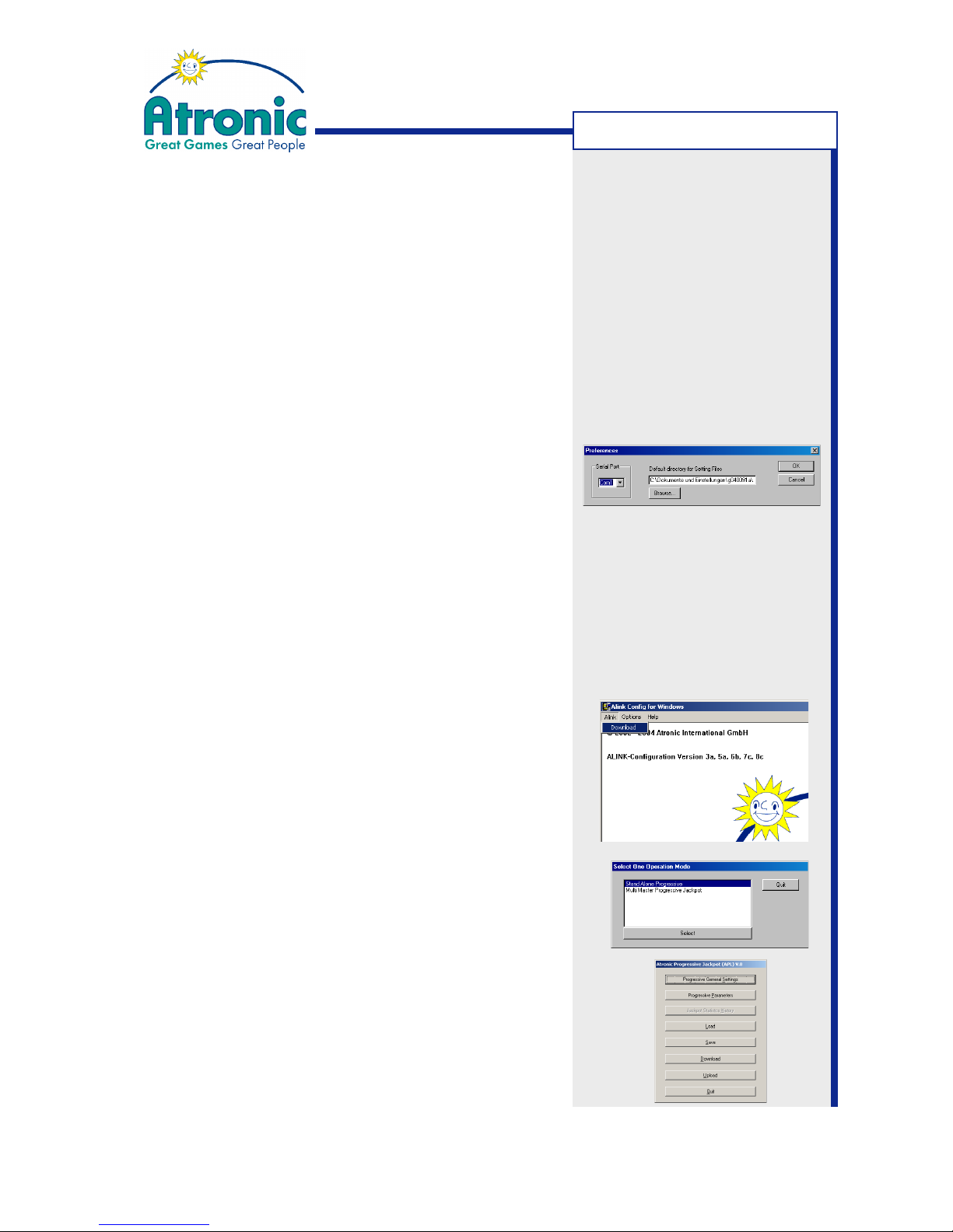
3. Download current Jackpot configuration.
• For Atronic Cashline series:
Enter Service Menu and select "PC-Setup/Jackpot Configuration" and press center lit button
on the button panel.
• For Atronic Hi(!)bility / e-motion series:
Enter Service Menu and select "Settings/Jackpot Configuration" and press "Start Configurati-
on" button on the touch screen.
Select menu "Alink" on the PC and click on "Down-
load".
Cashline only
: Download has to be started simultaneous at PC and machine within a few seconds
to prevent a "Communication time out" error.
4. If the "Select one Operation Mode" menu is displayed, select an operation mode
Multi Master Progressive Jackpot - Several linked machines
Stand Alone Progressive - One machine only
If the program detects no link (stand-alone) this
menu is not displayed.
5. The APL configuration main menu is displayed.
APL
Page 29

29
January 2005
Progressive Jackpot
Setting up an Atronic Progressive Link
(Continued)
APL Jackpot Configuration (Continued)
6. Select "Progressive General Settings".
7. Enable and configure "In Machine Display".
This will add an additional window to the game
screen showing the current Jackpot amount.
Additional settings for in-machine display:
Currency Enter a 3 digit ASCII string, which is
displayed trailing or leading the JP value
Currency Position Position of the currency string
Thousand Separator Enter "," or "."
Decimal Separator Enter "," or "."
Odometer Enables a smooth counting of the JP value
8. Choose "Overhead Display Type", if a display is connected to P7 on the Commboard.
9. Confirm settings with "Save & Quit".
10.Select "Progressive Parameters".
11.Set "Type" of JP 1 to NORMAL, to enable a progressive Jackpot.
Do not activate JP 2 to JP 8. These additional
Jackpot levels are reserved for Multi Level Jackpot systems such as Cashfever™ or Towerline™.
12.Edit Jackpot settings for JP 1
Current Value Enter current Jackpot value
(if reconfiguring a running Jackpot
or as an initial value)
Base Value Base Value + Hidden Value = New Jackpot
start value after a Jackpot hit
Limit Upper limit for Jackpot value.
Further increments are paid into Hidden or
Overflow. "0" = No limit.
Increment (%) Percentage of credits wagered that
accumulates to the Jackpot value
continues on next page.
Note: Do not enable the "Tower
Box" feature, unless you
configure a Towerline™ machine!
Note: Currency strings "EUR"
and "GBP" are interpreted by
the software and will display "¤"
respective "£" symbol.
Note: The "Base Value" should
always exceed the machines
(non-progressive) Top Award.
Values for "Current Value",
"Base Value" and "Limit" are
given in currency.
APL
Page 30
30
January 2005
Progressive Jackpot
Setting up an Atronic Progressive Link
(Continued)
APL Jackpot Configuration (Continued)
13.Edit "Jackpot Name", "Text Color" and "Value Color".
Jackpot Name Is displayed alternating with the JP value on
the in-machine display
Text color Color of the "Jackpot Name" text
Value color Color of the displayed Jackpot value.
14.Edit "Jackpot Won Text", "Text Display Time" and "Value Display Time", if needed.
Jackpot Won Text This text is displayed upon Jackpot hit
Text Display Time Timespan "Jackpot Name" text is displayed
Value Display Time Timespan in sec. the JP value is displayed.
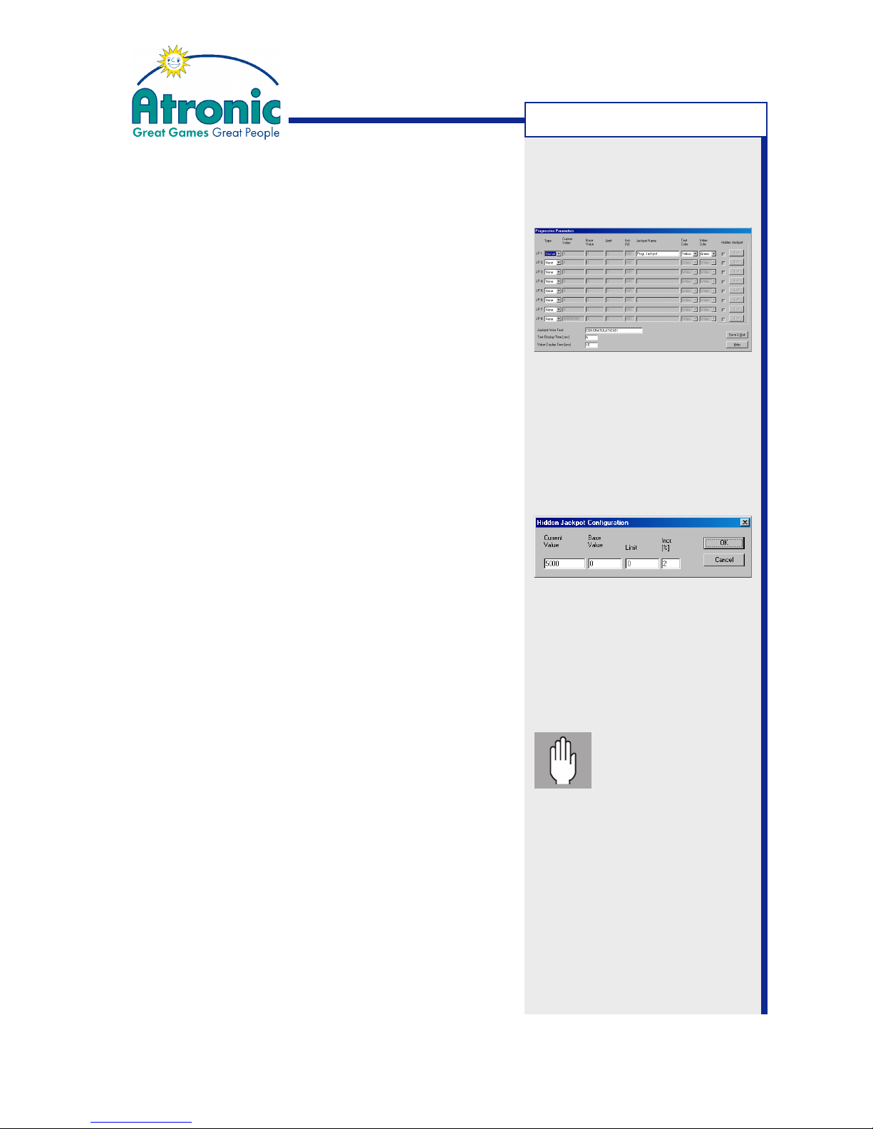
15.Enable "Hidden Jackpot", if needed.
16. Edit hidden Jackpot settings and confirm with "OK".
Current Value Enter current hidden Jackpot value
(if reconfiguring a running Jackpot
or as an initial value)
Base Value Hidden JP start value after a Jackpot hit
Limit Upper limit for hidden JP value. Further incre-
ments are paid into Overflow. "0"= No limit.
Increment (%) Percentage of credits wagered that
accumulates to the hidden JP value.
17. Confirm "Progressive Parameters" with "Save & Quit".
18.Check all settings carefully and select "Save" to
save settings to disk (optional).
19.Select "Upload" to send data to the machine.
20. Pay attention to application notes and confirm with
"OK" to start upload.
• For Atronic Cashline series:
Press center lit button to start upload.
21.When upload was successful, exit "Jackpot Configuration" menu, remove PC Setup Cable and close
Logic Box (e-motion only) and Main Door.
22.
e-motion machines only
Clear "Logic Door Open" message via Audit Key.
Important:
Check all settings
carefully before
uploading. Any subsequent modification of "Progressive Parameters" needs a RAM
reset on Main- and
Commboard!
Note: Values for "Current
Value", "Base Value" and "Limit"
are given in currency.
Note: "Jackpot Name" and
"Jackpot Won Text" supports
max. 16 characters. Use only
english alphabet. Country
specific characters (such as "ö"
or "é") are not displayed.
APL
Page 31

31
January 2005
Progressive Jackpot
Troubleshooting APL
APL: Duplicate Slave ID detected
This message occurs if at least two Slave machines
have the same address.
Solution: Change ‘Progressive System addresses’
to unique addresses from "01" to "32". Powercycle
machines with duplicate addresses for new
initializing.
APL: Link Not Allowed
There is no Security Chip with progressive feature
on the main board (P-GAL).
Solution: Install a Security Chip with progressive
feature.
APL: Configuration required
There is no Jackpot configuration.
Solution: Carry out Jackpot Configuration.
ALINK: Duplicate terminal ID detected
This message occurs, if at least two machines are
defined as master (DIP-switch S5/4 on Commboard).
Solution: Ensure that only one machine in the link is
defined as master.
APL: Progressive Not Connected
APL: Master not ready
Machine is not connected with APL master machine,
the power supply of the Alink network is not
connected or no master is defined in the link.
Solution: Connect machines with master. Connect
power supply for A-link™ network. Define one master
machine in the link.
ALINK: Please set valid terminal ID 1..32
Progressive system address has not been set or
has been set higher than "32".
Solution: Set progressive system address to an
address between "01" and "32" with commboard
rotary switches S1 and S2.
Note:
This message is also displayed
at all APL Slave machines prior
to Jackpot configuration.
Message expires when the
Master machine is configured.
Note:
This message is displayed at
APL Master machine prior to
Jackpot configuration.
Message expires when the
Master machine is configured.
APL TROUBLESHOOTING
Page 32

32
January 2005
Progressive Jackpot
Setting up a
Cash Fever™ Jackpot
CASH FEVER™
Page 33
33
January 2005
Progressive Jackpot
Setting up a Cash Fever™ Jackpot
Overview
Cash Fever™ is a complete gaming solution, which
consists of a set of connected Cash Fever™ slot
machines, a Cash Fever™ display system and a signage
including a plasma display screen.
Cash Fever™ utilizes a 4-level progressive Jackpot,
which is triggered by a special Bonus Game Session.
Basic setup
Cash Fever™ uses A-Link™ wiring and APL protocol to
connect the participating slot machines. Hardware
setup and basic software setup procedures are similar
as used for APL setup (see pages 23 - 27).
Different from APL configuration, Cash Fever™ Jackpot
configuration has some additional options and some
limitations (see next pages).
Additional requirements
External PC software "A-Link config for
Windows 2.1" or higher is required for Cash
Fever™ Jackpot configuration.
Check version index in program menu "Help / About".
Cash Fever™ Paytable Software
Machines linked in a Cash Fever™ Jackpot must have a
customized paytable software installed. Unlike standard
paytable software, Cash Fever™ paytable software has
a 4% Jackpot increment calculated into its Return to
Player percentage (RTP).
This has to be considered for Jackpot calculation,
especially if a sum of increments other than
(recommended) 4% has been set during Jackpot
configuration.
Note:
Cash Fever™ supporting game
software is only available for
e-motion™ slot machines.
CASH FEVER™
Example:
A Cash Fever™ paytable with a
nominally RTP of 94% has a RTP
of 90% in the base game plus
a (assumed) sum of increments
of 4% (which are payed into the
Jackpot).
Page 34
34
January 2005
Progressive Jackpot
Setting up a Cash Fever™ Jackpot
Link machines
In a Cash Fever™ bank machines are linked using Atronic
A-Link™ wiring connected to P10 and P11 on the
Commboard. P10 and P11 (RJ-45 Connectors) are
wired parallel, so it does not matter which one is used.
The end of the link is automatically terminated.
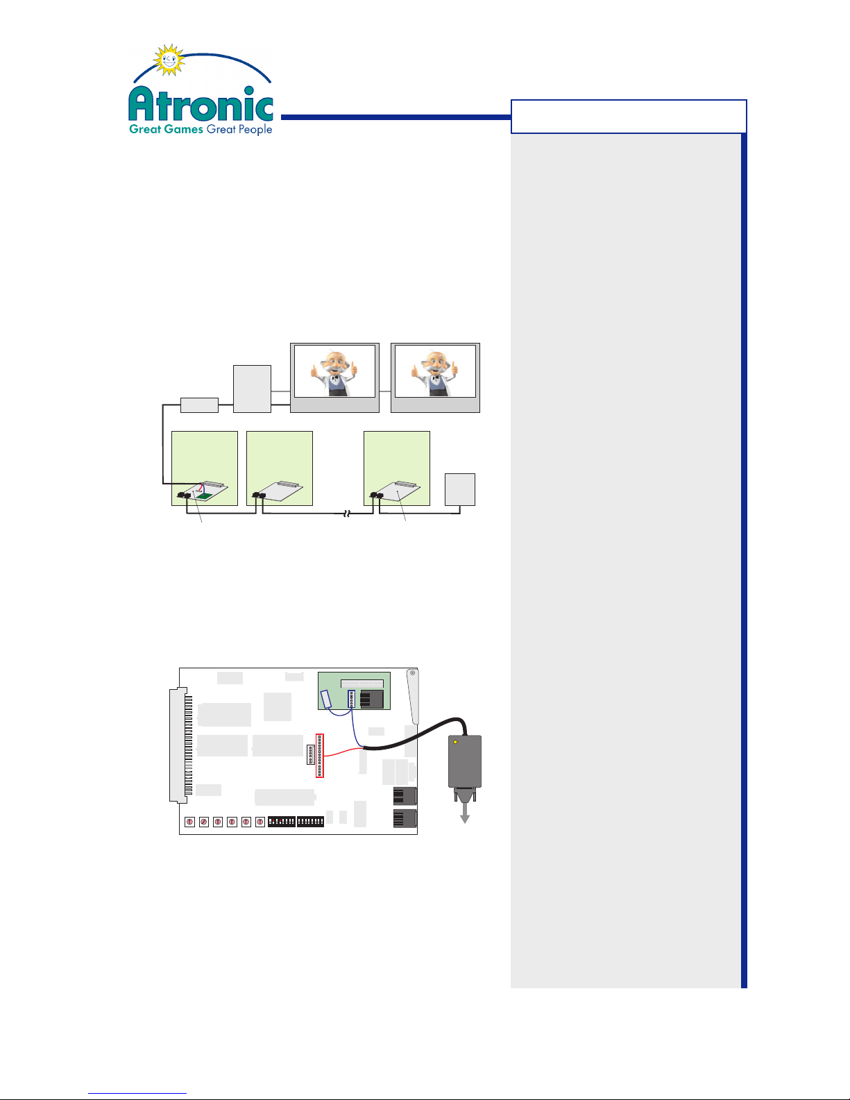
• The
Overhead Display Board
is plugged into P18
of the Master machine's Commboard.
• The
Cash Fever™ Converter
is connected to
Commboard P3 and Overhead Display Board P3
using cable
RS232_CF01A.
Necessary parts are delivered as a Cash Fever™ Kit
which consists of:
- Cash Fever™ Animation PC (with installed software)
- Cash Fever™ Connection Kit (Cables and converter)
- Atronic Overhead Display Board
Note:
When linking more than 16
machines a Power Supply Adapter WE8 - 2x WE8 has to be
connected in the middle of the
link. See APL Wiring on page 25.
EGM 1 EGM 2 EGM x
Commboard
Master
Cash Fever™Display
Cash
Fever™
PC
Commboard with Overhead Display Board
Converter
Cash Fever™Display 2
(max. 32)
APL
Power
Supply
Note:
See manual "Cash Fever™
Configuration Guide" provided by
Atronic Systems for details
about further Cash Fever™
display configuration.
P5
P18
P9
P10
P7
P3
P15
P12
P4
P19
P11
P14
P13
P2
P20
S1 S2 S3 S4 S6 S7
S5 S8
S9
5V
12V
U34 U35
U28
0
5
1
2
3
4
6
7
8
9
0
5
1
2
3
4
6
7
8
9
0
5
1
2
3
4
6
7
8
9
0
5
1
2
3
4
6
7
8
9
0
5
1
2
3
4
6
7
8
9
0
5
1
2
3
4
6
7
8
9
12345678
ON
12345678
ON
Battery 3.6V
+
P1
B1
CPU 68k
P17
P16
P4
P3
1
P2
Overhead Display Board
Commboard 68k
Rev. 2.10
Converter
Serial connection to PC
Not
c
o
n
nected
Note:
The second 6-pole MT plug is
reseved for future use. Do not
connect.
CASH FEVER™
Page 35
35
January 2005
Progressive Jackpot
Setting up a Cash Fever™ Jackpot
Prepare machines
Following procedure has to be carried out on every
machine participating in the link (except step 4 and 8).
1. Check if all pre-requirements are fulfilled.
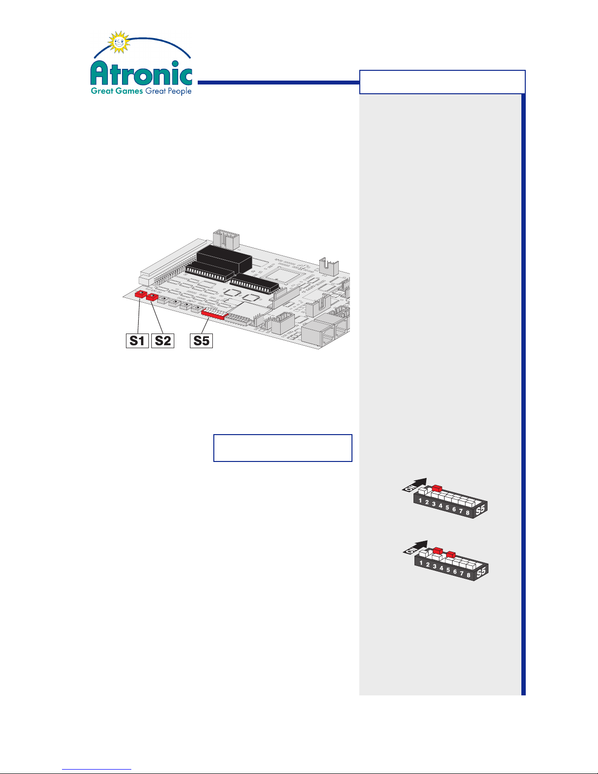
2. Set machines Progressive System Address with
rotary switches S1 and S2 on the commboard.
Each machine in the link must have a unique address
from "01" to "32". Set the Cash Fever™ Master
machine to adress "01".
S1: x10 (digit)
S2: x 1 (digit)
3. Activate APL mode on all linked machines.
Set Commboard switch S5 / 2 to ON.
Set switch S5 / 1, S5 / 3 and S5 / 4 to OFF.
4. Define one machine as Master by additionally setting
Commboard switch S5 / 4 to ON. This activates
implemented Jackpot controller functions.
APL Master
APL Slave
Commboard 68k
Example: For address "15"
set S1 to "1" and S2 to "5"
Note:
Address "00" is not valid.
CASH FEVER™
Page 36
36
January 2005
Progressive Jackpot
Setting up a Cash Fever™ Jackpot
Prepare machines
5. Carry out a RAM Reset on Main- and Commboard.
(described on page 55 and in manual "Software").
6. Carry out Initial Setup.
Necessary settings for Cash Fever™ are:
• Set "InMachine Progressive" to disabled
• Set Progressive Group to #00 (no group)
• Set "Commboard required" to YES
Other settings can be configured as needed.
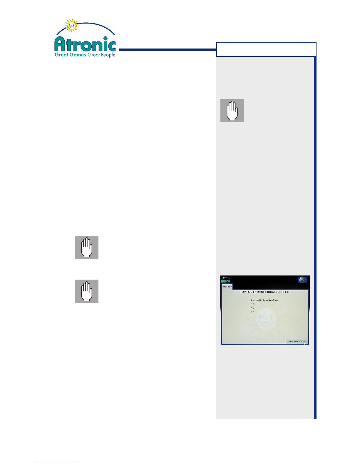
7. Paytable Configuration
(only if a selectable paytable is installed)
• Select Configuration Code
Please do only use that Configuration
Code stated on the Atronic Cash
Fever™ Calculation Sheet. Any other
configuration may lead to unpredictably
Return to Player values.
Configuration Code must be the same
on all machines in the link. If a machine
is configured to a different
Configuration Code as the Master
machine, this machine will be locked.
8. Carry out Cash Fever™ Jackpot configuration at the
APL Master machine using "A-Link Config" for Windows program version 2.1 or higher.
(as described on next pages).
Important: Do not
start any games or
insert credits after
RAM reset, until Jackpot
configuration is finished.
Note:
The Configuration Code defines
Cash Fever™ Base Values,
Jackpot Trigger Values
(Bounds) and Hitfrequency and
is assigned to a specific
paytable RTP-Family.
CASH FEVER™
Page 37
37
January 2005
Progressive Jackpot
Setting up a Cash Fever™ Jackpot
Cash Fever™ Jackpot Configuration
Jackpot configuration has to be carried out only on
the APL Master machine. When configuration is done,
the Master machine automatically sends the
configuration data to all linked Slave machines.
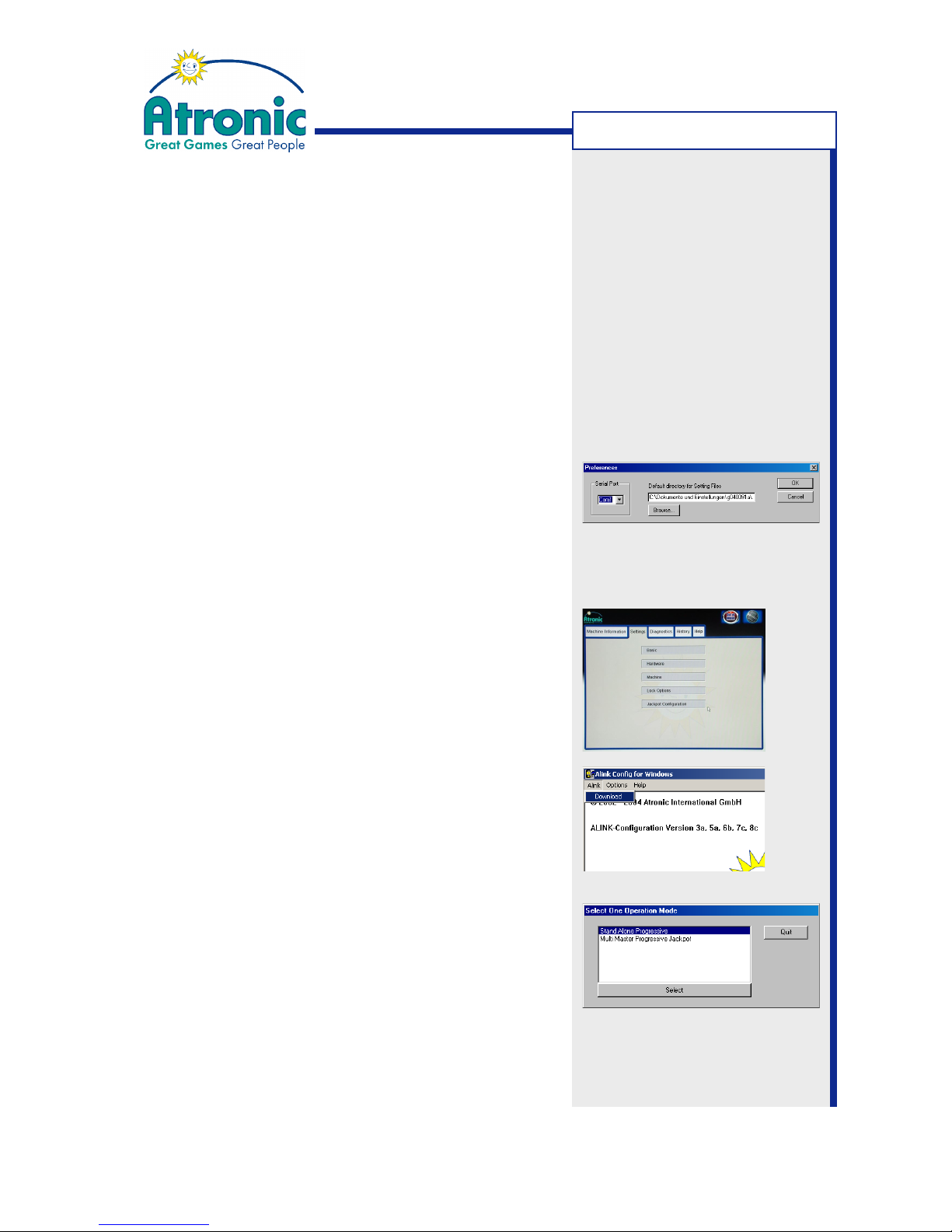
1. Prepare and connect PC or Laptop, (as described
on page 9) and start "A-Link Config" program.
2. (On first program start)
Select menu "Options" and click on "Preferences".
• Select the COM port where the PC-Setup cable
is connected to (default is COM1).
• Select a default directory to save setting files.
Confirm with "OK".
3. Download current Jackpot configuration.
Enter Service Menu at the machine and select "Settings / Jackpot Configuration" and press "Start Con-
figuration" button on the touch screen.
Select menu "Alink" at the PC and click on "Down-
load". Current settings are transfered from the
machine to the A-Link Config program.
4. When the "Select one Operation Mode" menu is
displayed, select operation mode "Multi Master Pro-
gressive Jackpot".
If the program detects no link this menu is not
displayed.
continues on next page.
Note:
Cash Fever™ Jackpot
configuration requires "A-Link
Config" version 2.1 or higher.
CASH FEVER™
Page 38
38
January 2005
Progressive Jackpot
Setting up a Cash Fever™ Jackpot
Cash Fever™ Jackpot Configuration (Continued)
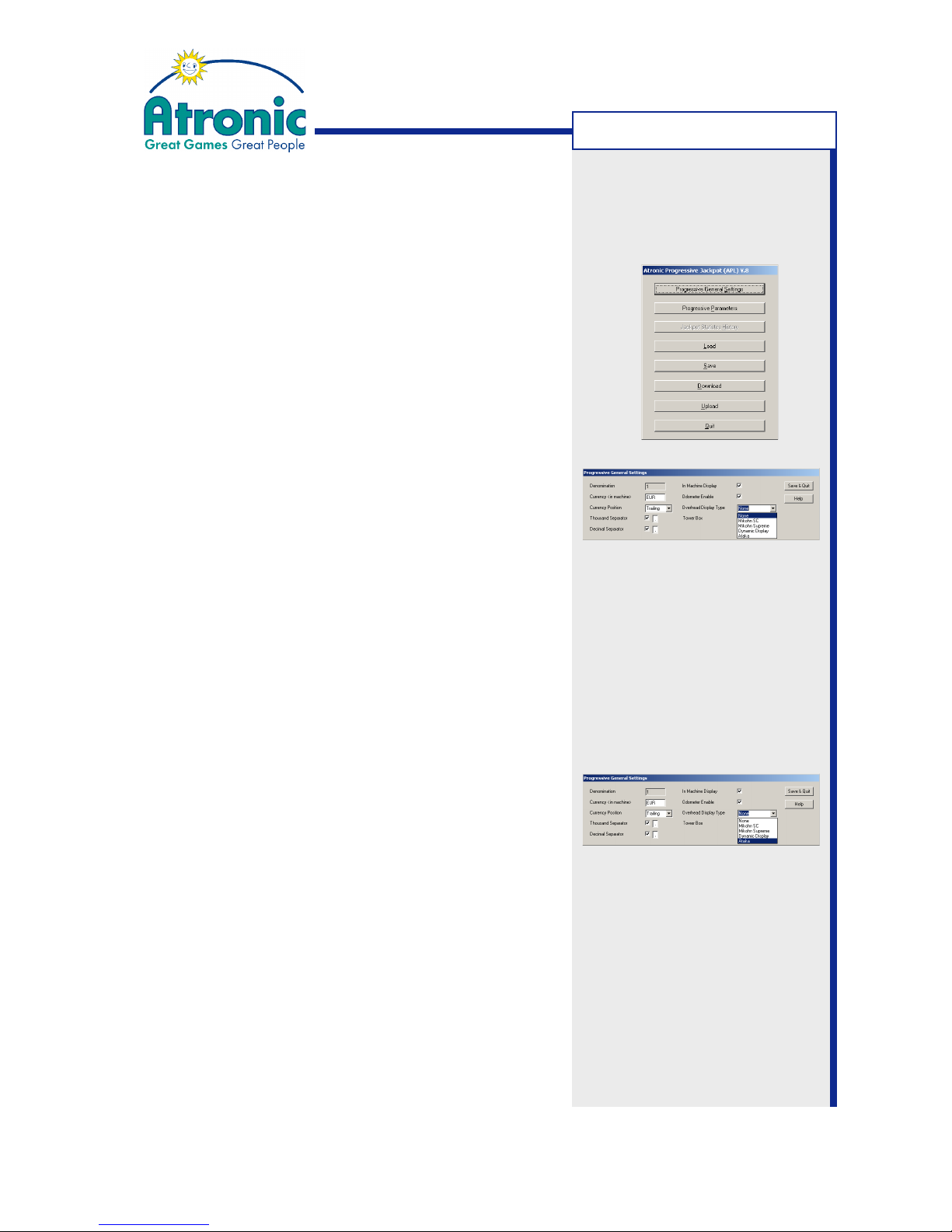
5. The APL configuration main menu is displayed.
6. Select "Progressive General Settings".
This will configure the display style of the Jackpot
values displayed on the machines upper screen.
Always mark checkbox "In Machine Display".
Additional settings for in-machine display:
Currency Enter a 3 digit ASCII string, which is
displayed trailing or leading the JP value
Currency Position Position of the currency string
Thousand Separator Enter "," or "."
Decimal Separator Enter "," or "."
Odometer Enables a smooth upcounting of JP values
7. Choose "Overhead Display Type", ATAKA to comunicate to the Cash Fever™ PC.
8. Confirm settings with "Save & Quit".
continues on next page.
Note:
Do not enable the "Tower Box"
feature.
Note:
Currency strings "EUR" , "USD"
and "GBP" are interpreted by
the software and will display "¤"
respective "$" or "£" symbol.
CASH FEVER™
Page 39
39
January 2005
Progressive Jackpot
Setting up a Cash Fever™ Jackpot
Cash Fever™ Jackpot Configuration (Continued)
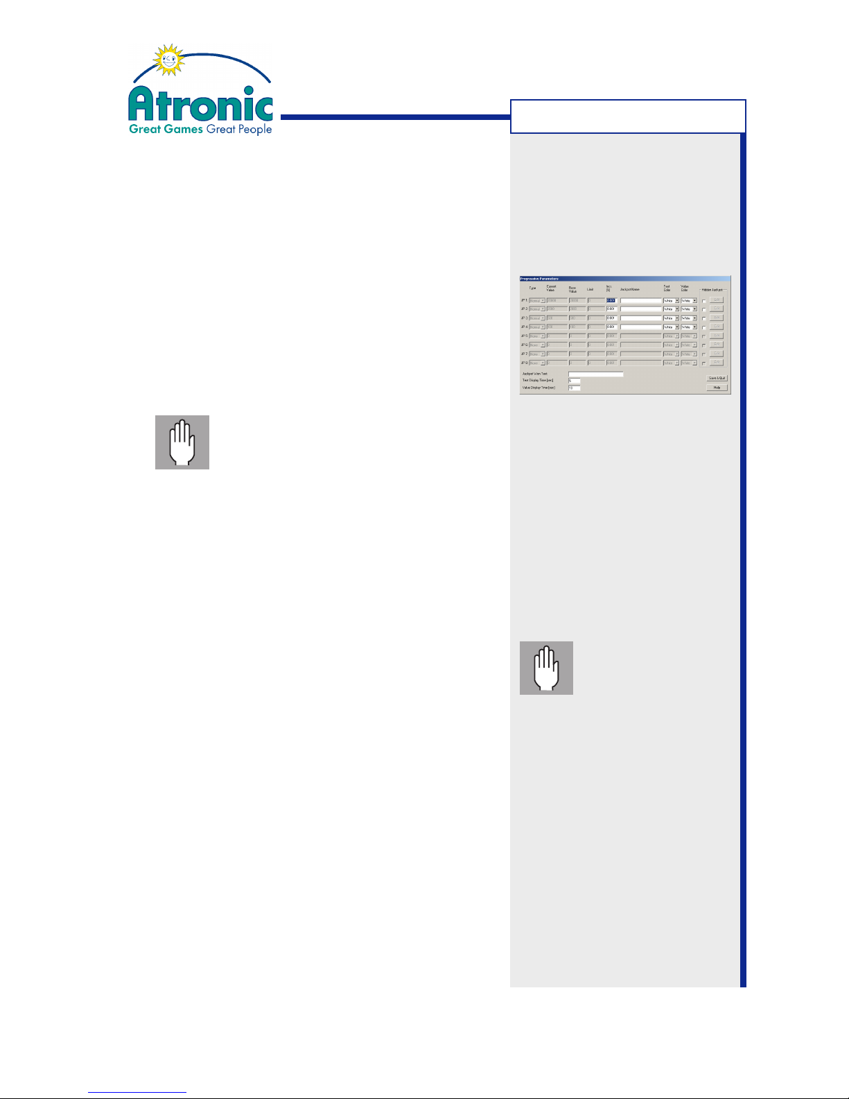
9. Select "Progressive Parameters".
10.Set an "Increment %" value for each Jackpot level
JP1 to JP4.
If needed, enable a Hidden Jackpot by checking the
corresponding checkboxes. Set an "Increment %"
for each Hidden Jackpot.
Increment (%) Percentage of credits wagered that
accumulates to the Jackpot value
Important!: Please use only "Increment
%" values calculated by means of the
Atronic Cash Fever™ Calculation Sheet.
Any other values may lead to unpredictably
Return to Player (RTP) values including
RTPs exceeding 100% !
Further settings are not necessary. Values for "Current Value" and "Base Value" are pre-defined by the
paytable software and can not be altered. Other
items are not needed and any entry will be ignored.
11. Confirm "Progressive Parameters" with "Save & Quit".
12.Check all settings carefully and select "Save" to
save settings to disk (optional).
13.Select "Upload" to send data to the machine.
14. Pay attention to application notes and confirm with
"OK" to start upload.
15.When upload was successful, exit "Jackpot Configuration" menu, remove PC Setup Cable and close
Logic Box and Main Door.
16.Clear "Logic Door Open" message via Audit Key.
At this point Cash Fever™ Jackpot Configuration is
finished.
Important: Check all
settings carefully
before uploading. Any
subsequent
modification of "Progressive Parameters" needs a RAM reset
on Main- and Commboard!
CASH FEVER™
Note:
The display style of the Overhead (Plasma) Display has to be
configured seperately by means
of a configuration application
which is installed on the Cash
Fever™ PC. See manual "Cash
Fever™ Configuration Guide"
provided by Atronic Systems
for details.
Page 40

40
January 2005
Progressive Jackpot
- blank page -
Page 41
41
January 2005
Progressive Jackpot
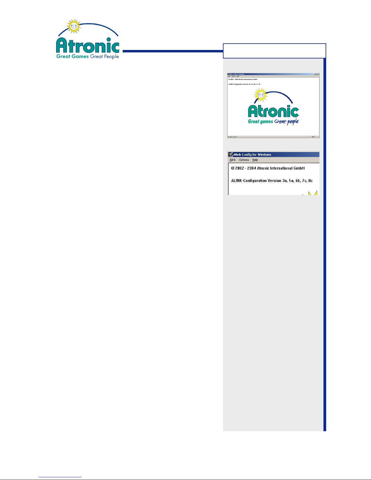
A-Link Config for Windows
Atronic's Alink Config for Windows (2.0 and higher)
was developed for computers running Windows® 9x,
ME, NT, 2000 or XP operating system.
Note: Alink Config for Windows 1.0 does not support
Windows XP® and Windows 2000®.
Alink Config DOS Versions
Jackpot configuration can either be carried out with
Alink Config for Windows or with one of the DOS program versions. Alink Config for Windows covers all
recent configuration versions in one application. ALink
Config DOS versions are specific programms for one
particular configuration version.
Alink Config for Windows 2.0 can be used instead of
DOS program versions CNFA03xx ,CNFA05xx,
CNFA06xx, CNFA07xx and AC08xx.
Installation
Alink Config for Windows requires installation of a
driver for the Hardlock Dongle (0300). The dongle is
required to unlock Alink Config for Windows.
1.Copy the two files "dongle_install.exe" and
"Alink_Setup.exe" from floppy disk into a temporary
folder on the PCs hard disk.
2. Run dongle_install.exe to install Hardlock Dongle
drivers and follow instructions on screen.
3. Connect Hardlock Dongle to PCs printer port, with
the PC switched off and reboot to initialize drivers.
4.Install Alink config for Windows by running
Alink_Setup.exe and follow instructions on screen.
5. Double click Alink Config icon to start Alink Config
for Windows.
A-LINK CONFIG
Page 42
42
January 2005
Progressive Jackpot
Atronic A-Link Config for Windows
Menu Structure
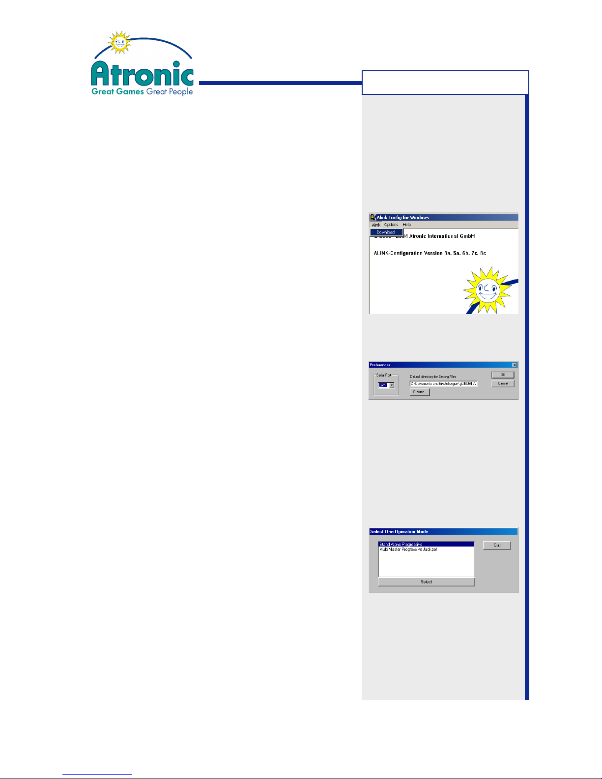
This section explains menu structure of Atronic's "ALink Config for Windows" program.
Alink/Download
Starts download of Jackpot Configuration data from
the machine into Alink Config program. This is always
the first step of Jackpot Configuration.
Options/Preferences
Serial Port
Used to set the PCs COM port to which the PC-Setup
cable is connected. Default is COM 1.
Default Directory for Setting Files
Click on "Browse" and choose a directory, where the
Jackpot Configuration setting files are to be stored.
Help
Opens help files.
Select one operation mode
After download of current Jackpot settings, an
operation mode has to be selected.
• Select "Stand Alone Progressive" for a progressive
Jackpot with only one machine.
• Select "Multi Master Progressive Jackpot" for a link
of several machines.
If the program detects no linked machines this menu
is skipped.
A-LINK CONFIG
Page 43
43
January 2005
Progressive Jackpot
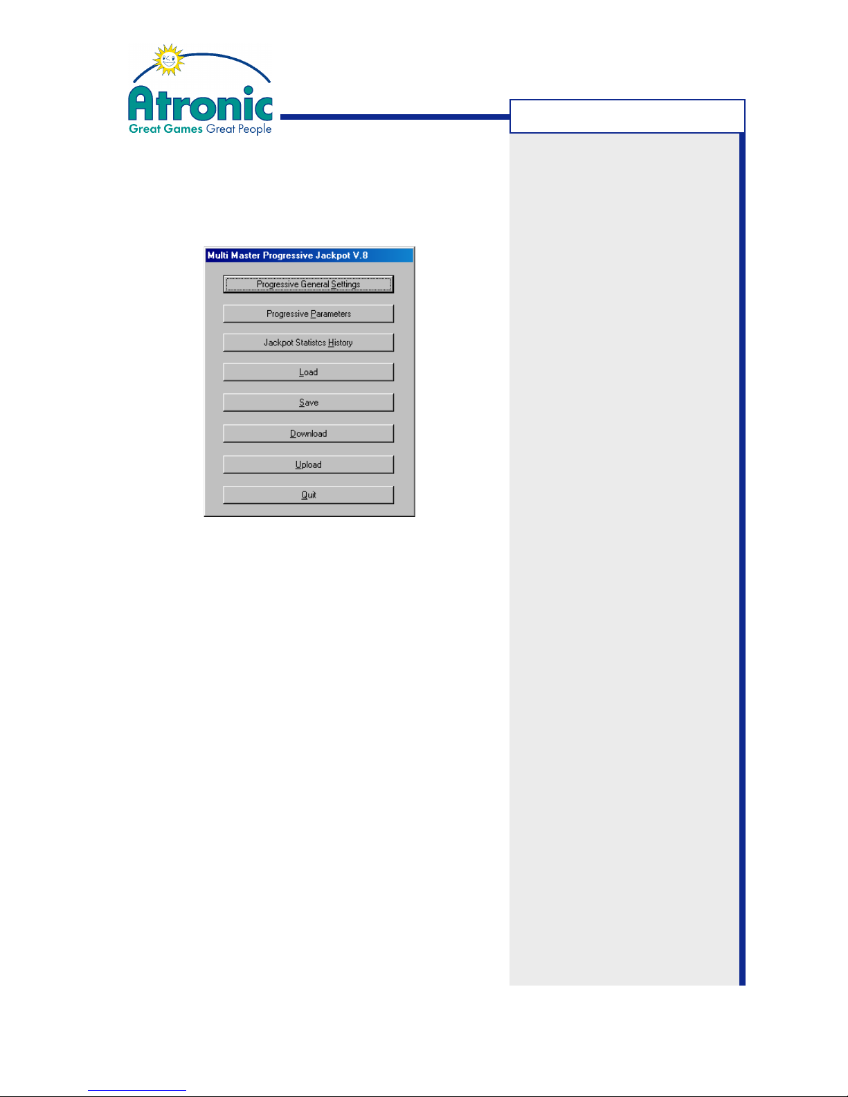
"Multi Master Progressive Jackpot V.8" - Menu
"Other Progressives (Mikohn, GRIPS or SAS)" - Menu
"Atronic Progressive Jackpot (APL)" - Menu
Progressive General Settings
Configure in-machine display and external display type.
Progressive Parameters
Enable progressive Jackpot and configure main settings.
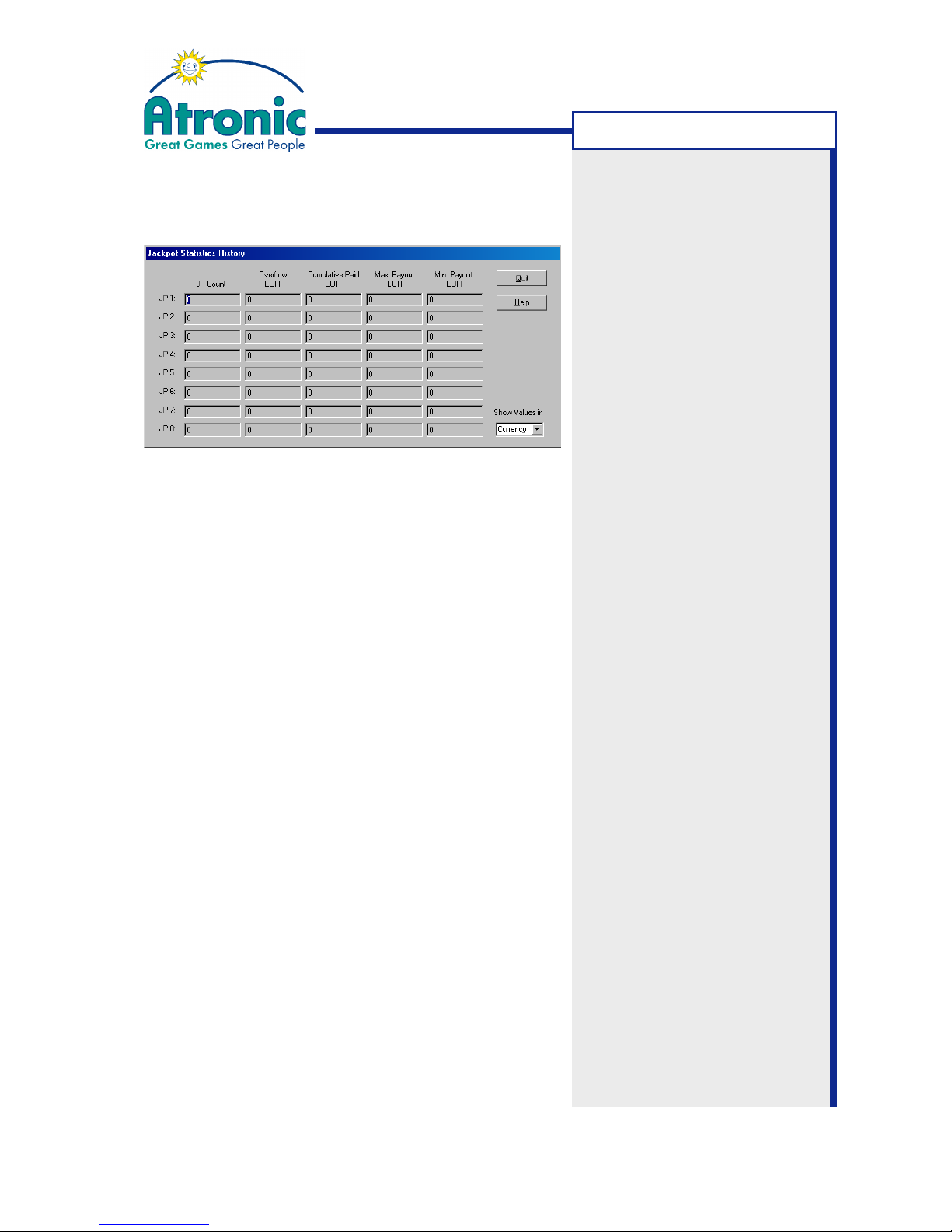
Jackpot Statistics History
Displays a summary of last Jackpots in credits or
currency.
Load
Load a previous saved Jackpot configuration setting
file into the program.
Save
Save current Jackpot configuration settings to disk.
Download
Download current Jackpot configuration data from the
gaming machine into the program. This is the first step
of every configuration procedure.
Upload
Upload Jackpot configuration data to the gaming
machine.
Quit
Quit Alink for Windows.
Note:
Depending on the configured
operation mode, this menu has
correlatively heading.
A-LINK CONFIG
Page 44
44
January 2005
Progressive Jackpot
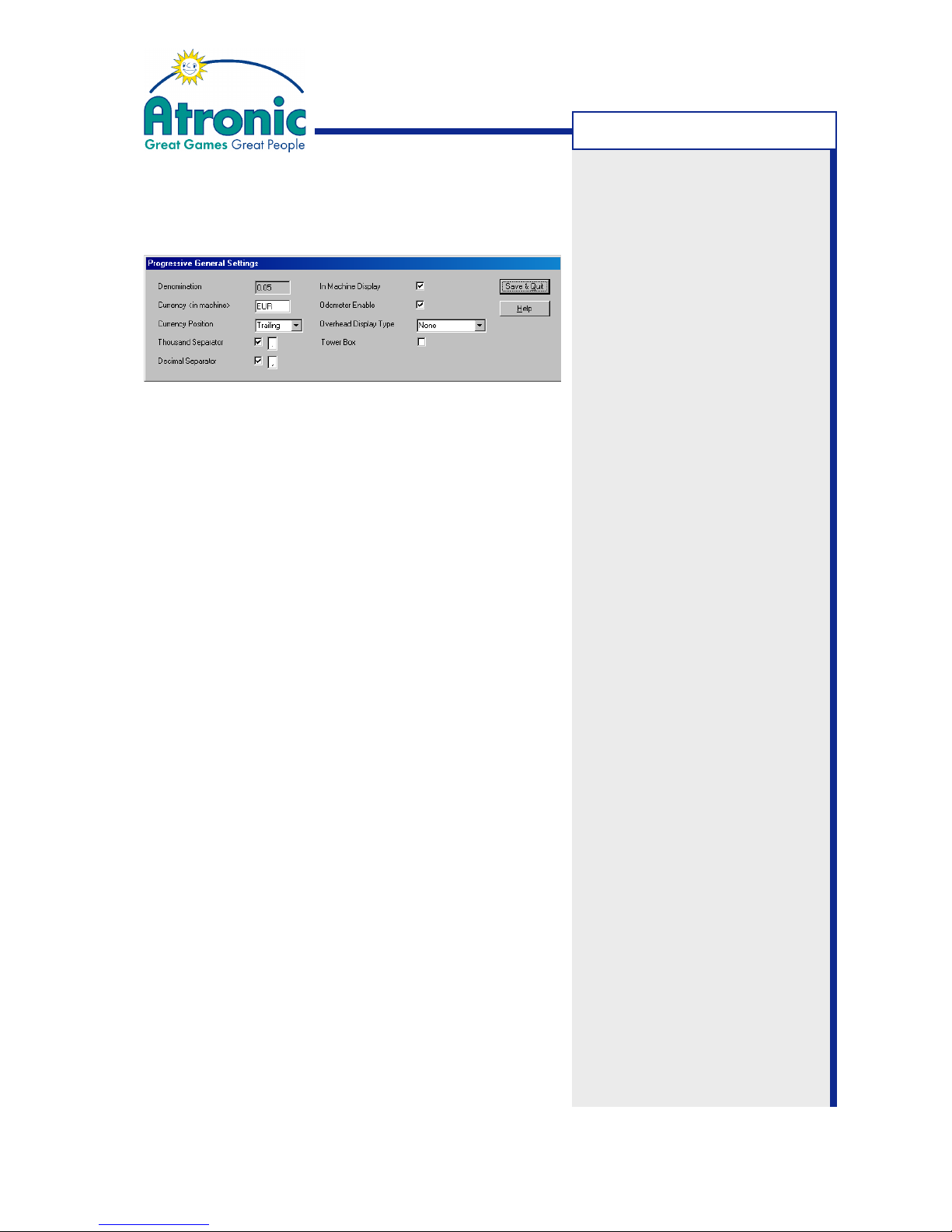
"Progressive General Settings" - Menu
Denomination
Shows machine's denomination.
Currency
The 3-characters "Currency" string is shown in the inmachine display, trailing or leading the Jackpot value.
Entering "EUR" or "GBP" will display a "¤" respective "£"
symbol.
Currency Position
The Currency string or symbol is displayed TRAILING
or LEADING the Jackpot value.
Thousand Separator
If activated, the specified symbol is inserted after each
third digit.
Decimal Separator
If activated, the specified symbol is inserted and the
decimal is displayed.
In Machine Display
If enabled, "Jackpot amount" / "Currency" and "Jackpot
Name" is displayed in an additional window at the top
of the game screen.
Odometer Enable
If enabled, the in-machine display smoothly counts up
to a new Jackpot value. If disabled, a changed Jackpot
value is displayed instantly.
Overhead Display Type
Depending on the display type (connected to
Commboard P7) select: NONE, MIKOHN SC (Super
Chameleon), MIKOHN SUPREME, DYNAMIC DISPLAY
or ATAKA.
Tower Box
Use only for Atronic Towerline™ series. Please refer to
Towerline configuration manual. Do not enable at other
machines!
Note: Do not enable the "Tower
Box" feature, unless you
configure a Towerline™ machine!
A-LINK CONFIG
Page 45
45
January 2005
Progressive Jackpot
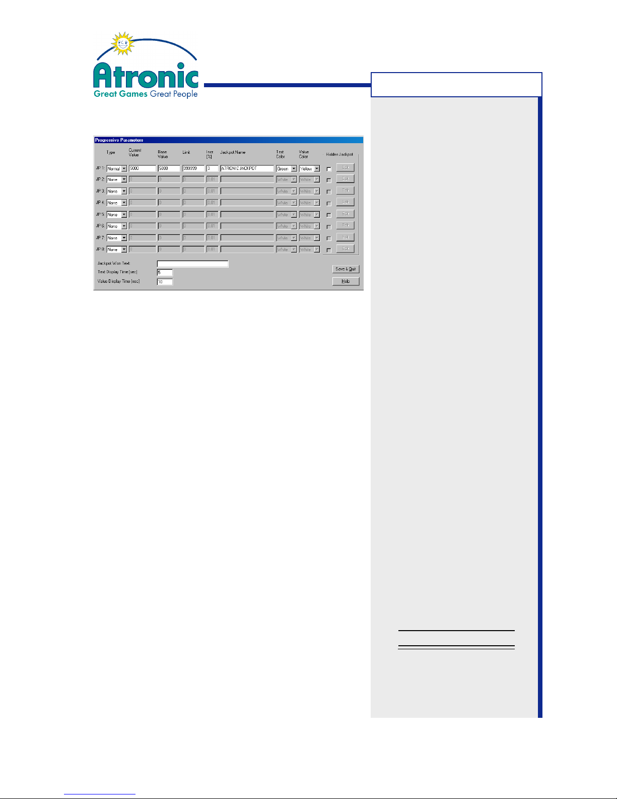
Progressive Parameters
Type (see next page for details)
Set to NORMAL for a Progressive (Money) Jackpot or
to PRIZE for a Prize Jackpot. NONE disables Jackpot.
Current Value (in currency)
The "Current Value" is the Jackpot amount, which is in
the Jackpot at the time of configuration. It is also
used to set an initial value for the Jackpot.
Base Value (in currency)
The "Base Value" (plus the "Hidden Jackpot" value) is
the new Jackpot start value, after a Jackpot hit.
Limit (in currency)
Sets an upper limit for the Jackpot value. If adjusted
limit is exceeded, all additional increments are paid into
the corresponding hidden Jackpot or into the overflow.
Set to "0" to set no limit.
Increment %
Percentage of credits wagered that accumulates to
the Jackpot value. Range is 0.01% to 18%.
Jackpot Name
This text is displayed on the in-machine display (if
enabled) alternating with the Jackpot value.
Text Color
Adjust color of displayed "Jackpot Name" text.
Value Color
Adjust color of displayed Jackpot value.
Jackpot Won Text
This text is displayed in case of a Jackpot hit.
Text Display Time
Sets display time (in sec.) of "Jackpot Name" text,
before display alternates to Jackpot value.
Value Display Time
Sets display time (in sec.) of Jackpot value, before
display alternates to "Jackpot Name" text.
Note: The "Base Value" should
always exceed the machines
(non-progressive) Top Award.
Note: Please note that "Jackpot Increment Percentage" and
"Hidden Jackpot Increment
Percentage" add to the overall
Return to Player Percentage
(RTP).
RTP (from paytable)
+ Jackpot Inc. %
+ Hidden Inc. %
= Overall RTP (in %)
A-LINK CONFIG
Page 46

46
January 2005
Progressive Jackpot
Progressive Parameters (continued)
Money Jackpot - Type set to NORMAL
The linked EGMs will distribute their bets to the Master. The Master will accumulate these bets into a
Jackpot value, depending on the "Increment
Percentage".
Jackpot Value = Denomination x Credits wagered x Increment Percentage
(+ Base Value
or
Current Value)
The Master will broadcast the current Jackpot values
to all Slaves in the link every 2.5 seconds. If the Slave
doesn`t receive a Jackpot value within 10 seconds, it
locks up and displays the message MASTER NOT
READY or PROGRESSIVE NOT CONNECTED.
The Jackpot value can be limited, if a "Limit" value other
than "0" is set. If the Jackpot value exceeds this limit,
the increments are paid into the corresponding hidden
jackpot. Set to "0" for no limit.
On first power up after Jackpot configuration, the Jackpot value will be set to the adjusted "Current Value".
In case of a Jackpot hit, the Jackpot value is awarded
to that EGM, which has caused the trigger event. The
EGM that hits the Jackpot locks up and displays the
Jackpot value and the "Jackpot Won Text" and has to
be cleared by an attendant.
After a Jackpot hit, the new (start) value is set to:
Jackpot Start Value = Base Value + Hidden Jackpot Value
The hidden Jackpot value is then set to the hidden
Base Value.
Prize Jackpot - Type set to PRIZE
If this Jackpot type is selected, the Jackpot level is
associated to a fixed prize, which is displayed by a text
message in case of a Jackpot hit.
Note:
The Jackpot trigger event is
defined in the paytable
software. Usually it is the
machine's Top Award win
combination.
A-LINK CONFIG
Page 47
47
January 2005
Progressive Jackpot
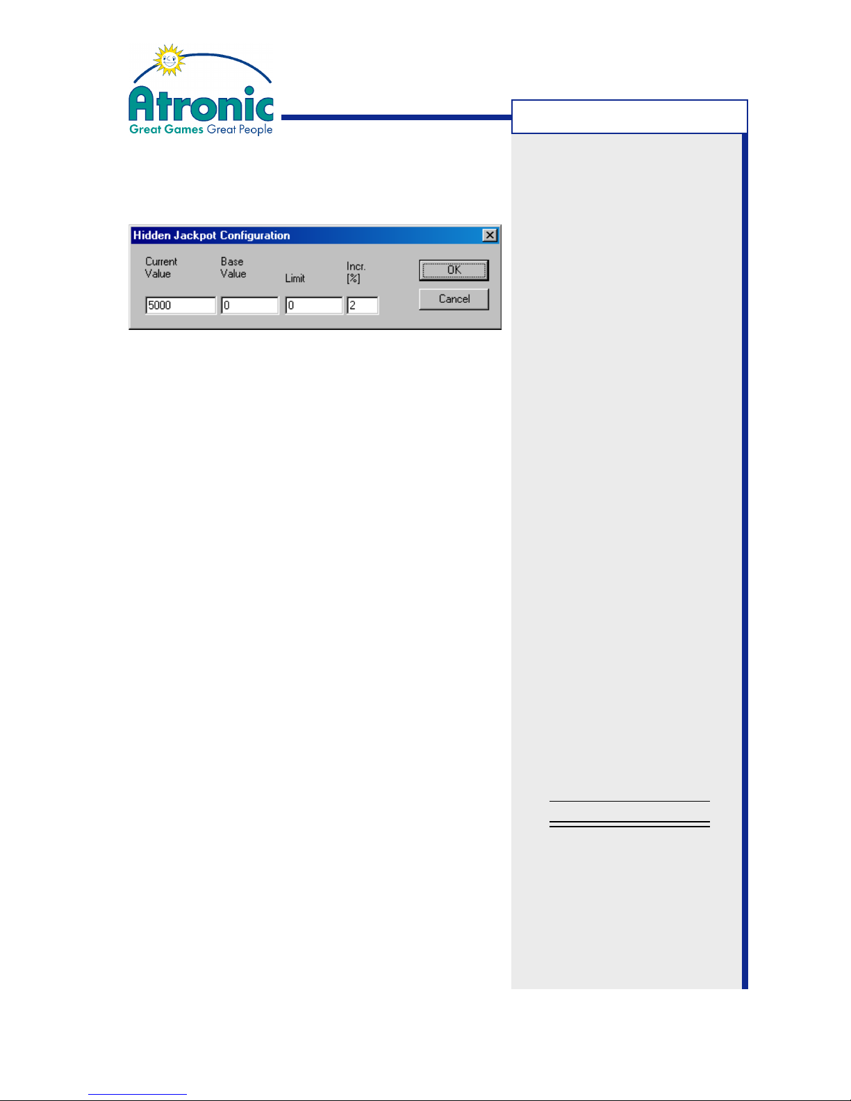
Hidden Jackpot Window
Current Value (in currency)
The "Current Value" is the amount, which is in the hidden
Jackpot at the time of configuration (Initial value).
Base Value (in currency)
The "Base Value" is the new hidden Jackpot start value,
after a Jackpot hit.
Limit (in currency)
This field sets an upper limit for the hidden Jackpot
value. If this limit is exceeded, additional increments
are paid into the overflow. Overflow value can be seen
in the "Jackpot Statistics History". If set to "0", there
is no limit for hidden Jackpot value.
Increment %
Sets percentage of credits wagered paid into the
hidden Jackpot. Range is 0.01% to 18%.
Hidden Jackpot enabled
If enabled, the Hidden Jackpot increases with every
credit wagered.
Hidden Value = Denomination x Credits wagered x Hidden Incr. Percentage
(+ Hidden Base Value or Hidden Current Value)
After a Jackpot hit, the Hidden Jackpot value is transferred to the normal Jackpot (added to the Jackpot
Base Value).
Jackpot Start Value = Base Value + Hidden Jackpot Value
New Hidden Jackpot (start) value is the hidden Base
Value.
Note: Please note that "Jackpot Increment Percentage" and
"Hidden Jackpot Increment
Percentage" add to the overall
Return to Player Percentage
(RTP).
RTP (from paytable)
+ Jackpot Inc. %
+ Hidden Inc. %
= Overall RTP (in %)
A-LINK CONFIG
Page 48
48
January 2005
Progressive Jackpot
Jackpot Statistics History
Jackpot Count
Displays number of Jackpot hits.
Overflow
Displays the amount that could not be accumulated
to the Jackpot or the hidden Jackpot.
Increments are paid into the "Overflow",
- if adjusted hidden Jackpot limit is exceeded
- if adjusted Jackpot limit is exceeded and
hidden Jackpot is disabled.
Cumulative Paid
Displays sum of all Jackpot wins.
Max. Payout
Displays largest Jackpot win.
Min. Jackpot Payout
Display smallest Jackpot win.
Show values in
Select CURRENCY or CREDITS.
Values in "Jackpot Statistics History" window can be
displayed in currency or credits.
A-LINK CONFIG
Page 49
49
January 2005
Progressive Jackpot
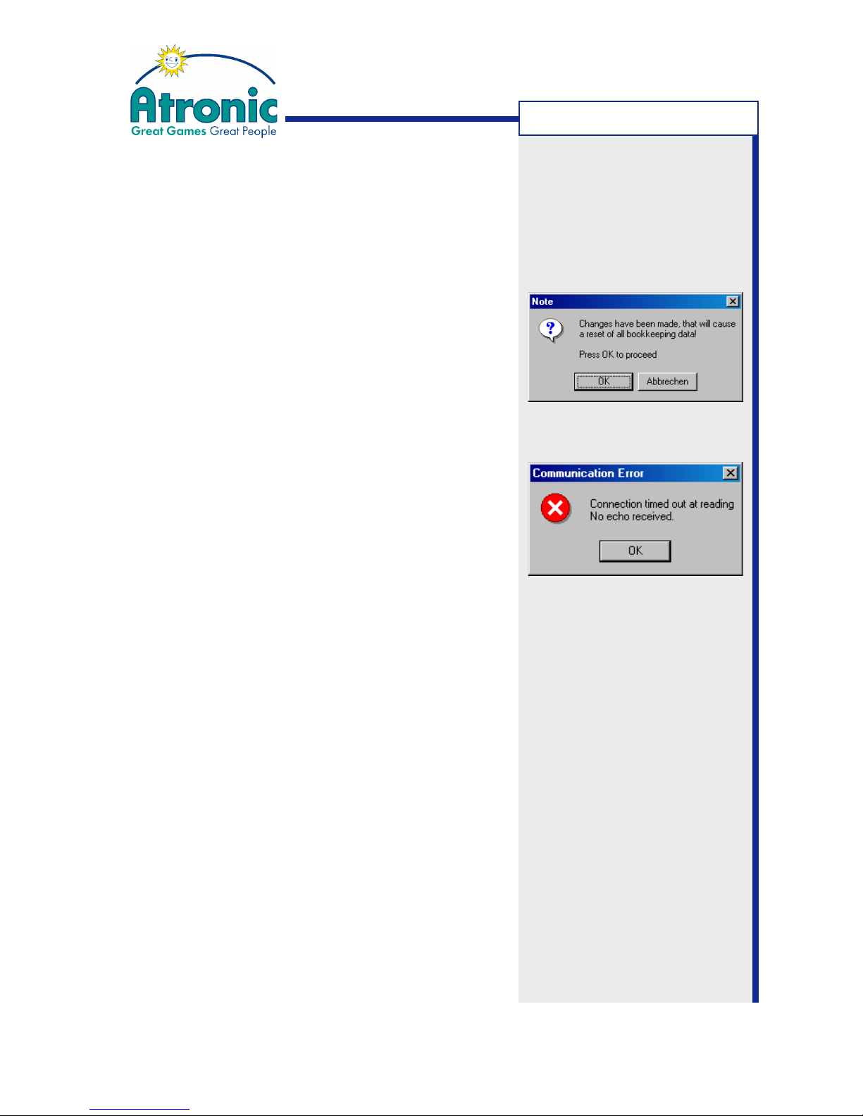
Application Messages
In order to inform users in important matters, the
program will display certain messages.
Reset Confirmation:
This message will appear, if the configuration requires
a reset of bookkeeping data.
Communication Error:
This message will appear, if download of Jackpot data
is not possible.
Possible reasons:
• Wrong or defective (serial) setup cable
-> Use Atronic PC-Setup cable (from Alink setup kit)
• Cable not connected
-> Check cable for proper connection
• Wrong COM port selected
-> Set COM port via menu Options/Preferences
• Wrong program version
-> Alink Config for Windows 1.0 does not support
Windows XP and Windows 2000®.
Press Start on Slot Machine:
This message will appear every time the communication between configuration program and the gaming
machine is started.
A-LINK CONFIG
Page 50

50
January 2005
Progressive Jackpot
Appendix
APPENDIX
Page 51
51
January 2005
Progressive Jackpot
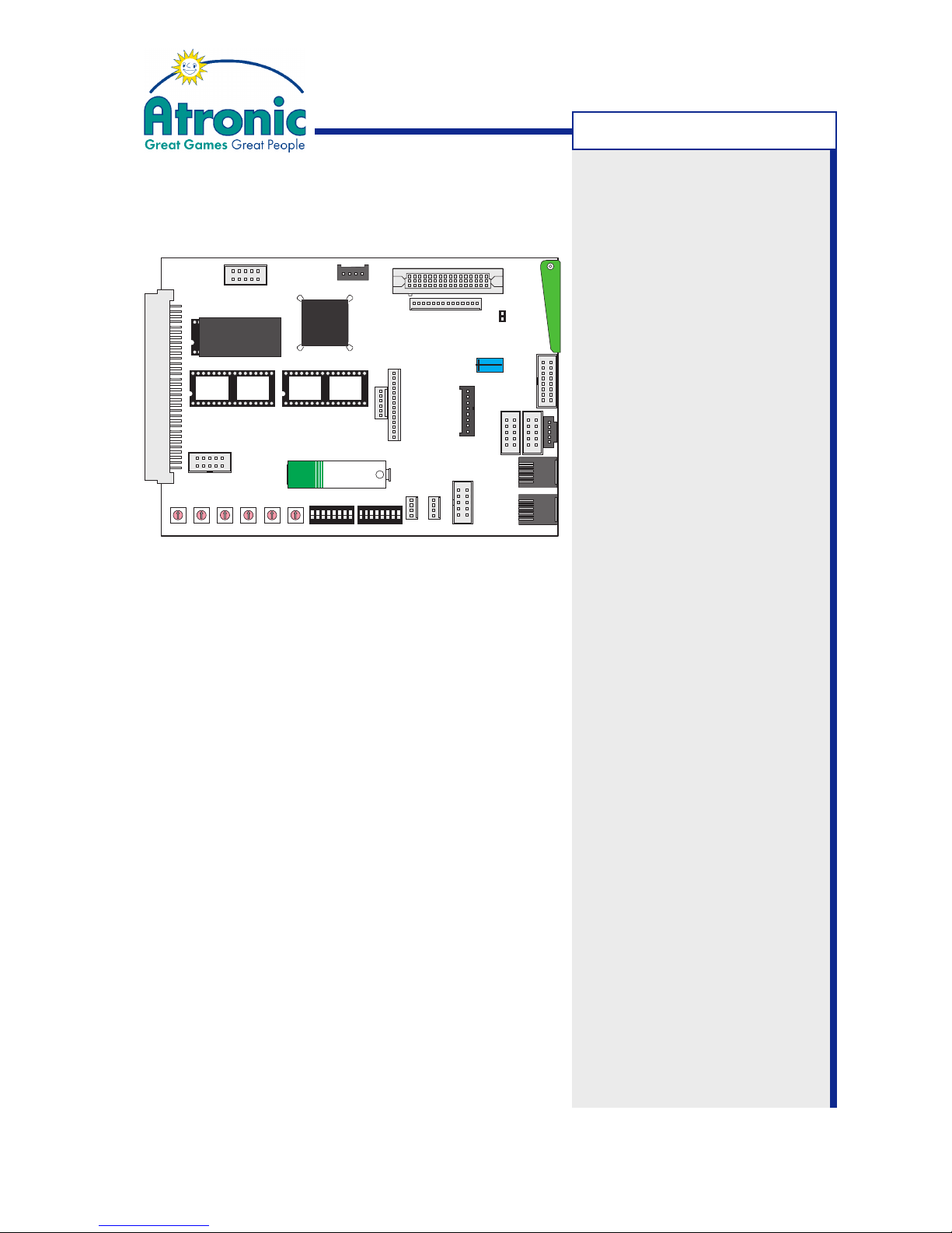
Commboard 68k Rev. 2.10
Connectors and Switches Overview
Connector Interface Protocol / Function
P2 TTL SAS channel 1 (current loop)
P3 - Cash-Now trigger signals
P4 RS232 SAS channel 2
or
GRIPS
P5 - Comm Key (Ticket in dongle)
P7 - External Display
P9 - +12V
P10, P11 RS485 A-LINK, Mikohn Controller
or
SAS channel 3
P12 RS232 SAS channel 1
P13 TTL Bally
P14 TTL DACOM
P15 - not used
P16 RS422 VLC
P17 - Manufacturer use
P18 RS422 Overhead Displayboard CL
P19 TTL SAS channel 2 (current loop)
P20 - not used
S9 Close to apply +5V or +12V to pin 1 of connector P2
B1 Close jumper to bridge electrical (galvanic) isolation
of ground connection.
Connector function depends on implemented protocol
version of Comm board software.
Note: Connectors P10 and
P11 are parallel wired.
P5
P18
P9
P10
P7
P3
P15
P12
P4
P19
P11
P14
P13
P2
P20
S1 S2 S3 S4 S6 S7
S5 S8
S9
5V
12V
U34 U35
U28
0
5
1
2
3
4
6
7
8
9
0
5
1
2
3
4
6
7
8
9
0
5
1
2
3
4
6
7
8
9
0
5
1
2
3
4
6
7
8
9
0
5
1
2
3
4
6
7
8
9
0
5
1
2
3
4
6
7
8
9
12345678ON12345678
ON
Battery 3.6V
+
P1
B1
CPU 68k
P17
P16
APPENDIX
Page 52
52
January 2005
Progressive Jackpot
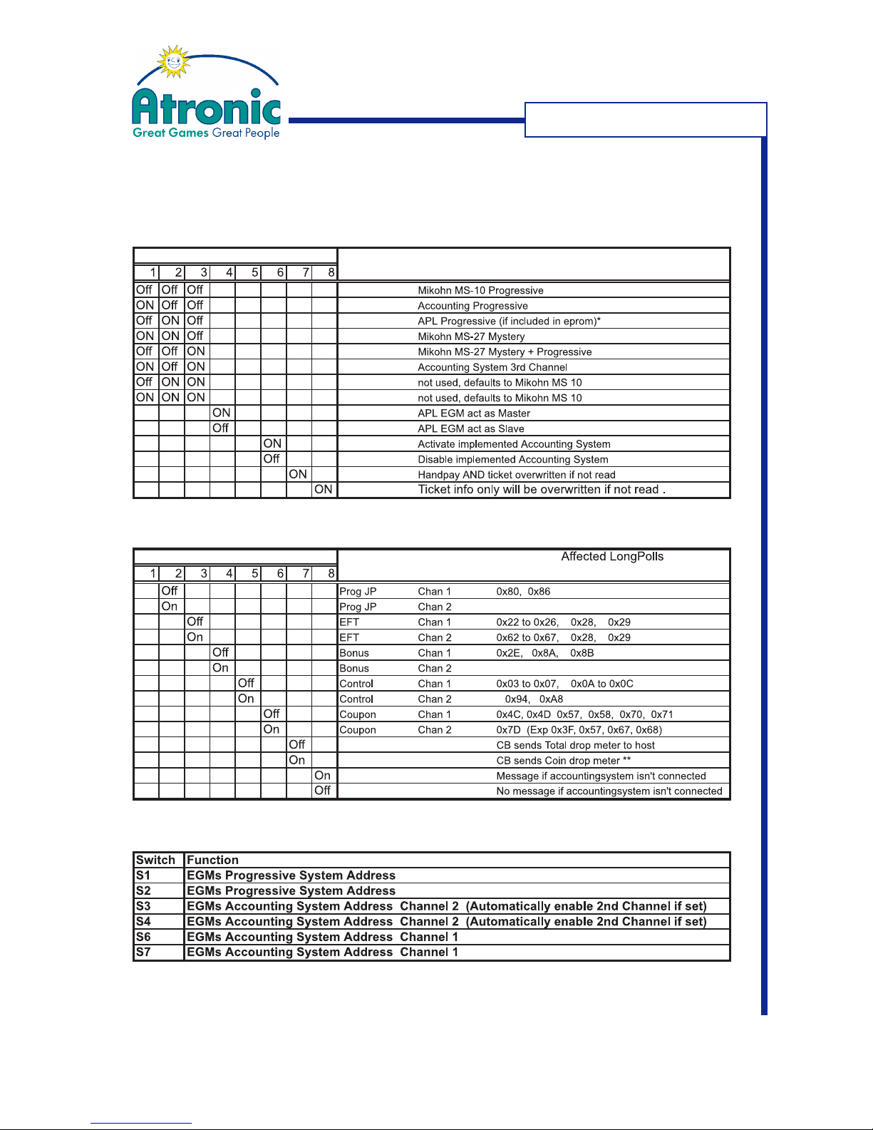
Commboard 68k Rev. 2.10
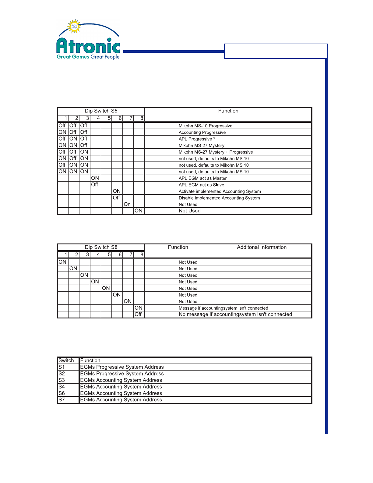
DIP Switch Overview for SAS Protocol
DIP Switch S5
DIP Switch S8
Rotary Switches
on P10 and P11
Tables refer to Commboard software using SAS protocol
Cashline™ - O-Level (Update 2003-1) and Hi(!)bility™- Q-Level
APPENDIX
Page 53
53
January 2005
Progressive Jackpot
Commboard 68k Rev. 2.10
DIP Switch Overview for GRIPS Protocol
DIP Switch S5
DIP Switch S8
Rotary Switches
Tables refer to Commboard software using GRIPS protocol
Cashline™ - O-Level (Update 2003-1) and Hi(!)bility™- Q-Level
APPENDIX
Page 54

54
January 2005
Progressive Jackpot
Commboard 68k - EPROM Naming Scheme
By means of the EPROM naming scheme the Commboard software version can be
identified. EPROM naming is available on EPROM label or in menu "Audit Menu/
Configuration".
12345678910111213141516171819
Q _ - S 5 - MJ - S T D _ - B - 0 8 A
1-2 Communication Level with Mainboard (O-, P-, or Q-Level)
4-5 Protocol Identifier, Accounting / Communication System
7 Hardware (M= Commboard 68K)
8 Release
10-12 Jurisdiction (STD= Standard)
13 Release Type ( _= Final)
15 Progressive Revision Level
17-18 Structure Version Progressive / Alink Config program version
19 Dongle Version
Protocol Identifier:
03 VLC Australia
04 Xseries
06 Qcomm
B0 Bally Simple Serial
S4 SAS 4.xx
S5 SAS 5.xx
G4 GRIPS 4.00x
Progressive Revision Level
_ No progressive available
A APL
B MS10, MS27, APL,
System Progressive (SAS, GRIPS), Three Channel Progressive (SAS only)
C Same as "B" with additional Cash Fever™ functionality via APL.
Progressive/Alink Structure Version:
07 Use "CNFA07xx.exe" or "A-Link Config for Windows" for Jackpot configuration.
08 Use "AC08xx.exe" or "A-Link Config for Windows" for Jackpot configuration.
__ Progressive/ALINK Setup not available
Dongle Version:
A Dongle for „Ticket In“ (Comm Key)
B-Z Future Versions/Types of dongles
_ Dongle not available or not supported
APPENDIX
Page 55
55
January 2005
Progressive Jackpot
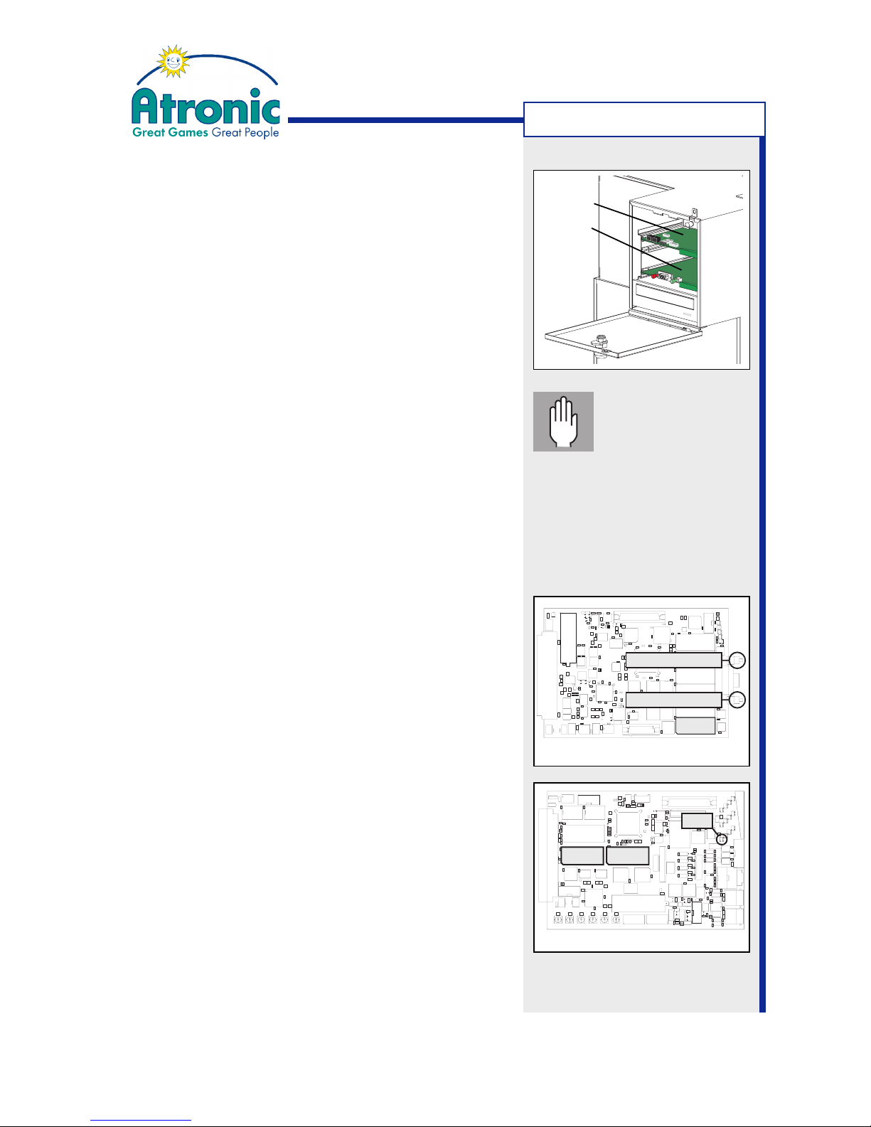
RAM Reset / Clear Memory Procedure
for e-motion / Hi(!)bility series
1. Open Main Door and switch machine power off.
2. Open the Logic box door and remove Main board
and Comm board.
3. Replace Paytable EPROM on Main board socket U9
with RAM Reset EPROM "HMB-RRES01".
4. Replace EPROMS on Comm board socket U34 and
U35 with two Comm board Clear EPROMS "Q-CBRAM-CLEAR". The socket to use is labeled on the
EPROMs. Check for correct mounting!
5. Reinstall Main board and Comm board and switch
machine power on.
6. Wait approximately 2 minutes until an audible si-
gnal and a message on the main display confirms
that RAM Reset was successful.
A flashing LED (D19) on the Comm board confirms
that Comm board Clear was successful.
7. Switch machine power off and remove Main board
and Comm board.
8. Replace RAM Reset EPROM "HMB-RRES01" with
original Paytable EPROM U9.
Check for correct mounting!
9. Replace both Comm board Clear EPROMS with
original Comm Software EPROMS U34 & U35.
Check for correct mounting!
10.Reinstall Main board and Comm board and switch
machine power on.
11.Wait approximately 2 minutes until a message is
displayed on the main display and follow the instructions on screen (Press red reset button).
12.The machine will now automatically enter Initial
Setup for basic setup.
Proceed with Initial Setup
Service Switch
Reset Switch
U9
MAIN BOARD
COMM BOARD
D19
U34 U35
Caution!
Make sure to have
the EPROM mounted
correct. The sockets'
groove and the EPROMs groove
have to point to the same
direction. Wrong insertion will
cause permanent damage to
EPROMs and boards.
Comm board
Main board
APPENDIX
Page 56
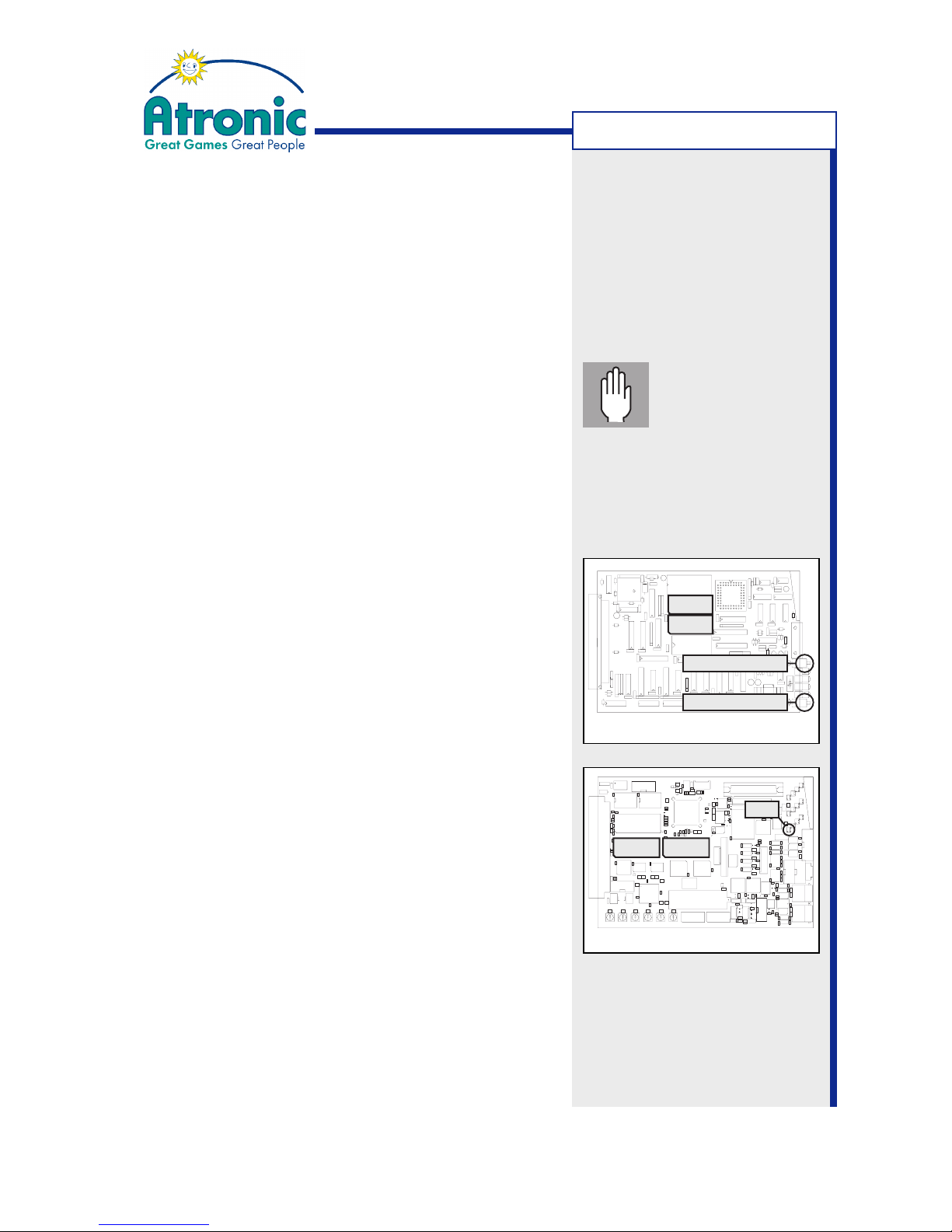
56
January 2005
Progressive Jackpot
RAM Reset / Clear Memory Procedure
for Cashline series
using RAM Reset 09 (RRES_09) EPROM
1. Switch off power and remove Master- and Comm board.
2. Replace Main EPROM U2 on the Master board with
RAM Reset EPROM "RRES_09".
3. Replace Paytable EPROM U6 on the Master board with
CONFIG Key EPROM.
4. Replace Comm EPROMS U34 & U35 on the Comm board
with COMM CLEAR EPROMS.
5. Reinstall Master- and Comm board and switch on power.
6. Wait approx. 10 seconds. An audible signal confirms
RAM RESET and a flashing LED (D19) on the Comm
board confirms COMM BOARD CLEAR.
7. Switch off power and remove Master- and Comm board.
8. Replace RAM Reset EPROM "RRES_09" with original
Main EPROM.
9. Replace COMM CLEAR EPROMS with original Comm
software EPROMS U34 & U35.
10. Reinstall Master- and Comm board and switch on power.
11. After some seconds the message "CONFIG EPROM
DETECTED, PLEASE RESTART WITH ORIGINAL
PAYTABLE EPROM (U6)" is displayed.
12. Switch off power and remove Master board.
13. Replace CONFIG Key EPROM U6 with original paytable
EPROM.
14. Reinstall Master board and switch on power.
15. After some seconds the message "RAM ERROR" is
displayed.
16. Press and hold the red reset button for approx. 5
seconds (until you hear an audible signal).
Proceed with Initial Setup.
MASTER BOARD
U6
U2
Service Switch
Reset Switch
COMM BOARD
D19
U34 U35
Perform step 3, 11, 12, 13
and 14 only when using a
selectable paytable!
Caution!
Make sure to have
the EPROM mounted
correct. The sockets'
groove and the EPROMs groove
have to point to the same
direction. Wrong insertion will
cause permanent damage to
EPROMs and boards.
APPENDIX
 Loading...