

Page 1

www.atronic.com
Atronic e²-motion™
Installation Manual
Rev. 1.2
June 2008
Page 2

2
June 2008
e²-motion™ Installation Manual
RELEASE INFO
Release Info:
Atronic e²-motion™
Installation Manual
Rev. 1.2
June 2008
WARNING!
This manual is intended to provide QUALIFIED TECHNICAL PERSONNEL ONLY with
the information necessary to install the e²-motion™ cabinet and components. To avoid
personal injury or damage to the equipment, do not perform any servicing other than
that contained in this manual.
Copyright Notice:
© 2008, Atronic. All rights reserved.
No part of this publication may be copied or distributed, transmitted, transcribed,
stored in a retrieval system, or translated into any human or computer language, in
any form or by any means, electronic, mechanical, magnetic, manual, or otherwise, or
disclosed to third parties without the express written permission obtained from a
properly authorized official of Atronic.
DISCLAIMER
Atronic makes no representation or warranties, express or implied, with respect to
this publication, or any product of Atronic, including but not limited to warranties of
merchantability or fitness for any particular purpose. Atronic reserves the right to
make changes, enhancements, revisions and alterations of any kind to this publication
or the product(s) it covers without obligation to notify any person, institution or
organization of such changes, enhancements, revisions and alterations.
TRADEMARKS
This document may contain trademarks of Atronic. All other brand and product names
are trademarks or registered trademarks of their respective companies.
Page 3

3
June 2008
e²-motion™ Installation Manual
Introduction
About this Manual
Scope, Target Audience, Included Software Releases ....
Related Publications ...................................................
Safety Instructions .........................................................
Machine Components .......................................................
Dimensions ......................................................................
Footprint / Drilling Template ...........................................
Technical Data ................................................................
Machine Installation
Overview ..........................................................................
Machine Mounting ............................................................
Topper Mounting ...............................................................
Replace Shipping Locks .....................................................
Prepare Coin Acceptor .......................................................
Prepare Hopper .................................................................
Check Connectors ..............................................................
Check Commboard Settings ................................................
Apply Power ......................................................................
Switch On .........................................................................
Basic Setup (Overview only) ..............................................
Tests ...............................................................................
Technical Support Telephone Numbers ..............................
4
5
7
10
13
14
15
17
18
20
21
21
21
21
22
22
22
23
24
25
CONTENT
Page 4

4
June 2008
e²-motion™ Installation Manual
ABOUT THIS MANUAL
Scope
This Installation Manual describes how to install an
Atronic e²-motion™ gaming machine.
It describes how to mount the machine to a base
stand and relevant procedures to be carried out before
the machine can be put into operation. Further it
contains important safety instructions, technical data
and cabinet drawings.
Target Audience
We address qualified technical personnel, who are
involved in installation, setup and configuration of
Atronic gaming machines. With this user group we
assume that they are basically familiar with gaming
machines and casino related terminology.
Please read this document and the contained safety
notes carefully before you start machine installation.
Included Software Releases
The installation procedures described in this manual
do not relate to a certain software version.
INTRODUCTION
Page 5

5
June 2008
e²-motion™ Installation Manual
ABOUT THIS MANUAL
Related Publications
More detailed information about Atronic e²-motion™
gaming machines may be found in the following
publications:
Software Manuals
• Manual HI Software (C4.x.x.x STD)
• Manual HI Software (C5.x.x.x STD)
Operation Manuals
• Manual E2M Operating (C4.x.x.x STD)
• Manual E2M Operating (C5.x.x.x STD)
Spare Parts
• Manual E2M Parts Catalogue.
Linked Gaming Products
• Manual [
product
] - Setup and Configuration
for a particular linked gaming product, such as
Mystery Magic™, Hot Link™, etc.
Peripherals
(Coin- and bill acceptors, hopper, printer, etc.)
• See folder "Peripherals" on the Atronic Service
Manual CD.
Note: All mentioned manuals can be found on a CDROM titled "Atronic Service Manual 2008"
If this manual did not came with this CD-ROM, please
ask Atronic Technical Service for a free copy of the
latest revision.
INTRODUCTION
Page 6

6
June 2008
e²-motion™ Installation Manual
- blank page -
Page 7
7
June 2008
e²-motion™ Installation Manual
SAFETY INSTRUCTIONS
SAFETY INSTRUCTIONS
Note!
This installation manual includes only information
relating to the installation of the e²-motion™ cabinet.
For other machine or cabinet types please refer to
the relevant manuals.
Follow the safety precautions below
and on the next page, to ensure safe
installation and operation.
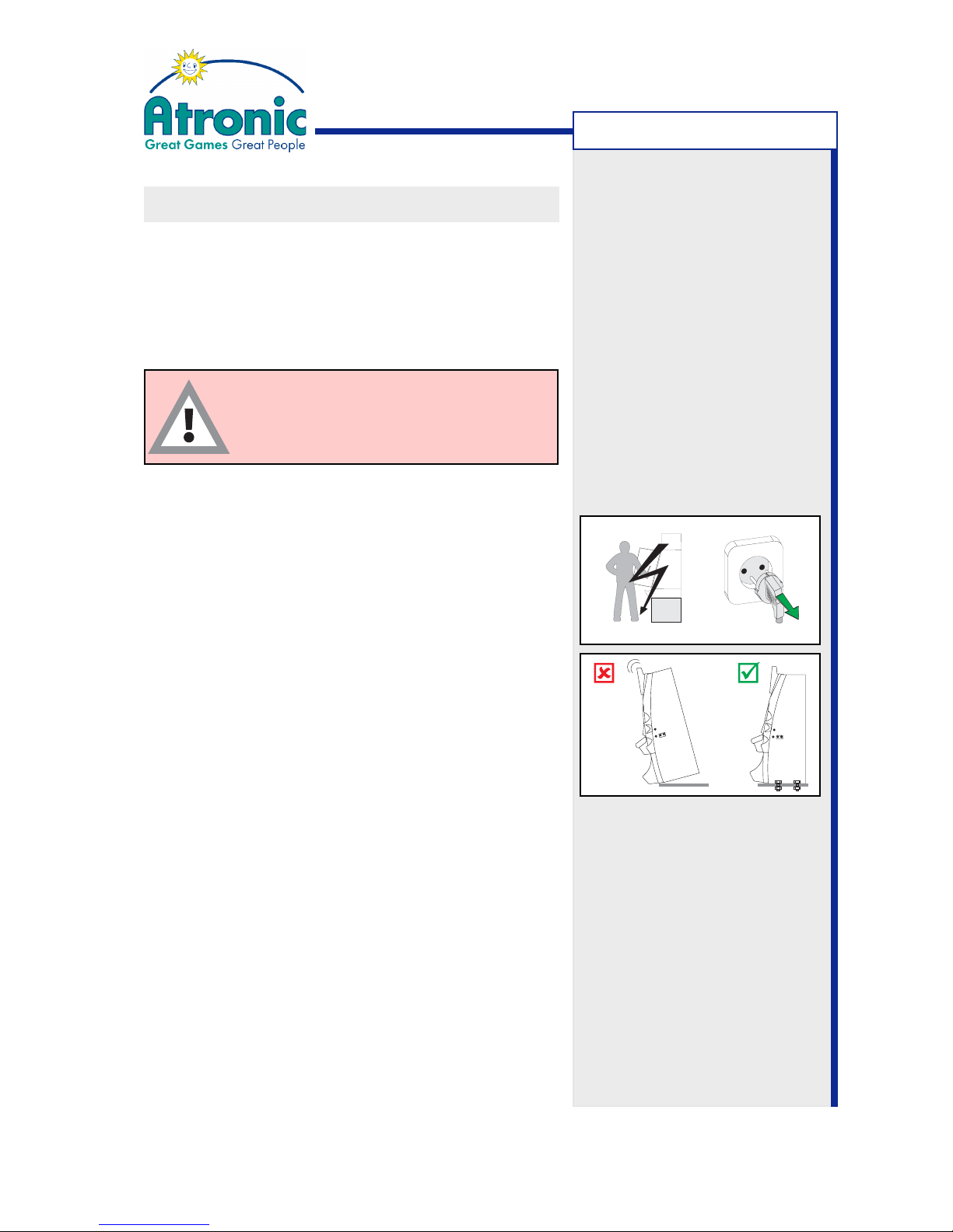
Caution! High Voltage
Power cable must be disconnected from the main
power socket, so that the machine is free from
electrical current. The power switch is intended for
service purposes only.
Caution! Tipping Hazard
The machine must be fastened to an appropriate base,
to prevent tipping over. Use the baseboard supplied
by Atronic for machine mounting.
-> see also page 17-18.
Caution! Moving Parts
Make sure to disconnect the hopper, when working
on it.
Caution!
The machine must not be cleaned using a high
pressure cleaner or a vapor jet and must not be
installed or operated in areas where high pressure
cleaners or vapor jets are used. Use in dry conditions
only.
Continues on next page
Page 8

8
June 2008
e²-motion™ Installation Manual
SAFETY INSTRUCTIONS
SAFETY INSTRUCTIONS
Further safety precautions during Installation,
Service and Maintenance
• The machine weight is approx. 114kg. Always use
appropiate equipment for transportation.
• Disconnect the power cable from the socket, before working at the machine.
• The machine may only be installed or operated in
dry conditions and must be connected to a grounded mains power socket.
• Check that all connectors are seated correctly. False connections can cause irreparable damage, not
covered by warranty.
• For power cable routing remove the knock-out plate on the appropriate side of the cabinet. Edgeprotection must be mounted once the knock-out
plate has been removed.
• Only qualified service personnel should perform
repairs.
• Electronic assemblies should only be changed with
the power switched off.
• Use only original Atronic parts for replacement.
• Atronic commboard and mainboard
Danger of explosion if battery is incorrectly replaced! Check for correct polarity and replace with
the same or equivalent type only!
• The machine must not be cleaned using a high
pressure cleaner or a vapor jet and must not be
installed or operated in areas where high pressure cleaners or vapor jets are used. Use in dry conditions only.
• Please refer to relevant Atronic service manuals
for further instructions on setup, operation and
maintenance.
Page 9

9
June 2008
e²-motion™ Installation Manual
- blank page -
Page 10
10
June 2008
e²-motion™ Installation Manual
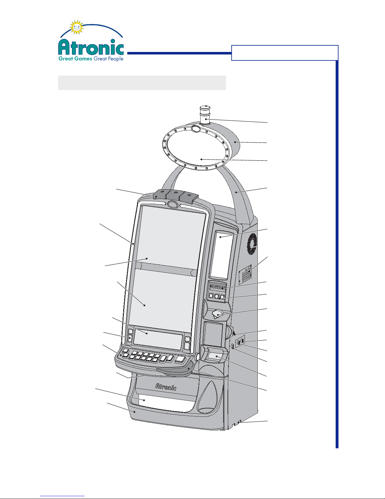
MACHINE COMPONENTS
M
ACHINE COMPONENTS
Topper Arch
Top Glass
Voucher Printer
(optional)
Coin Entry
Service Buttons
Main Door Lock
Jackpot Key Switch
Audit Key Switch
Hopper Drawer Lock
Bill Entry
Hopper Drawer
Type Plate
Coin Bowl
Hand Rest
Button Panel
Loudspeakers
Player Tracking
Unit (optional)
Lower/Main Screen
Mechanical Meters
(hidden)
Topper Glass
Framelights
Toplights
(or Blanking Cover)
Toplight
Upper Screen
Handle Receptacle
Topper
Page 11
11
June 2008
e²-motion™ Installation Manual
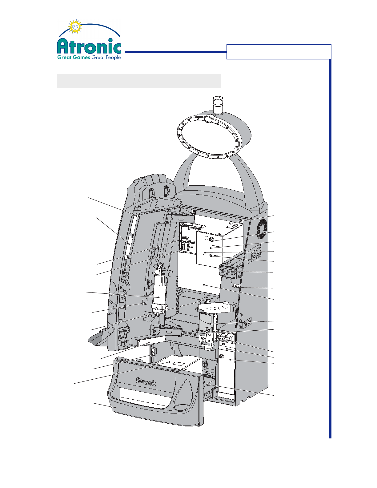
MACHINE COMPONENTS
M
ACHINE COMPONENTS
Logicbox
Voucher Printer
(optional)
Maindoor Switch
Bill Acceptor
- Head
- Stacker
- Cashbox
(behind optional door)
Hopper Drawer
Hopper
Door Motor
Filterboard Signal
Mechanical Meters
Top Glass Lighting
Hopper Drawer Switch
(hidden)
Coin Acceptor
Coin Optics Boards
Service Button
Reset Button
Logicbox Door
Logicbox Lock
Multimedia (MMPC)
Board Cover
Bill Door Switch
Filterboard Power
Top Glass
Release Lever
Button Panel
Release Button
Power Switch
Page 12
12
June 2008
e²-motion™ Installation Manual
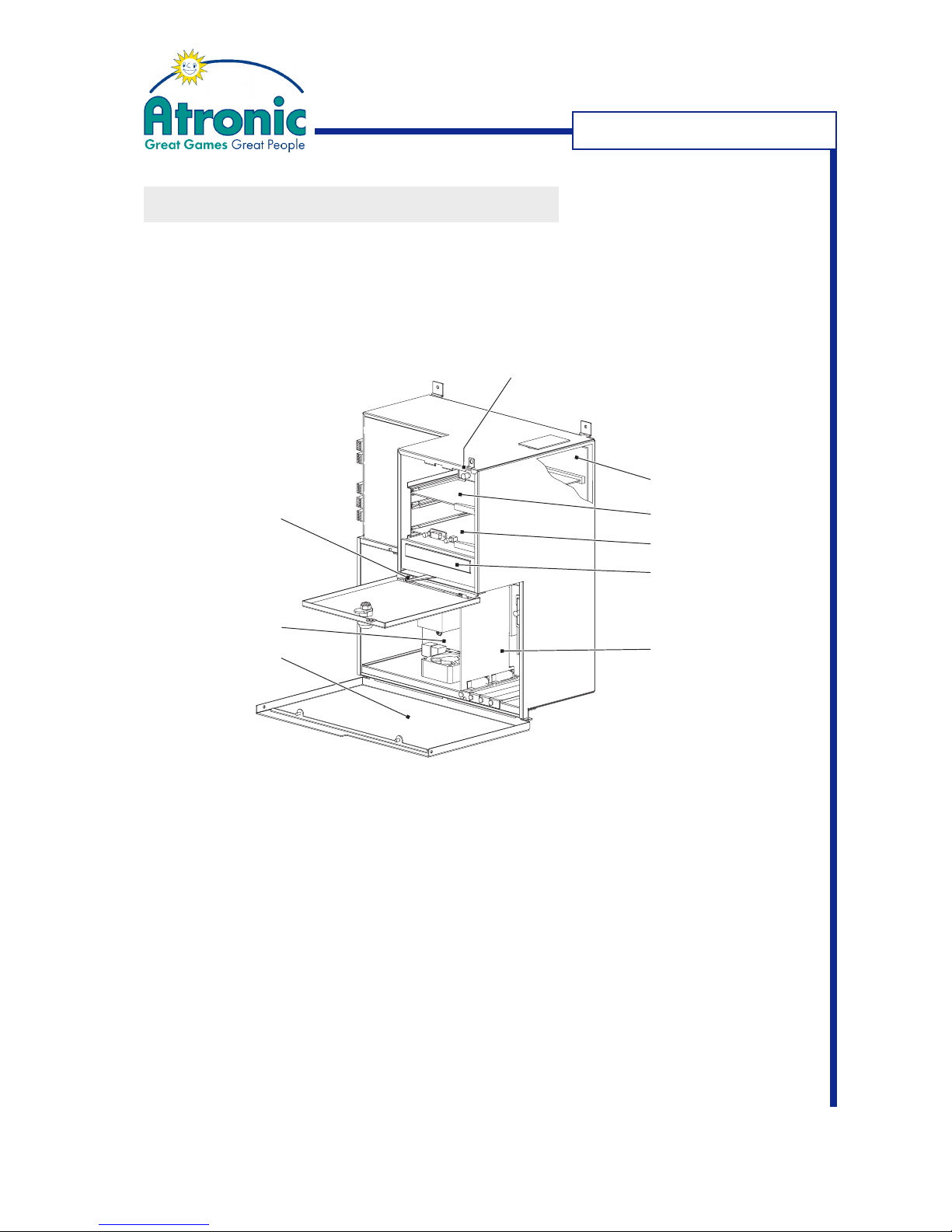
Logicbox Switch
Backplane
Commboard
Mainboard
DVD-ROM Drive
Graphic Card
(VP11)
Release Lever for
Multimediaboard
Cover
Multimediaboard
Multimediaboard
Cover
MACHINE COMPONENTS
Logicbox
MACHINE COMPONENTS
Page 13
13
June 2008
e²-motion™ Installation Manual
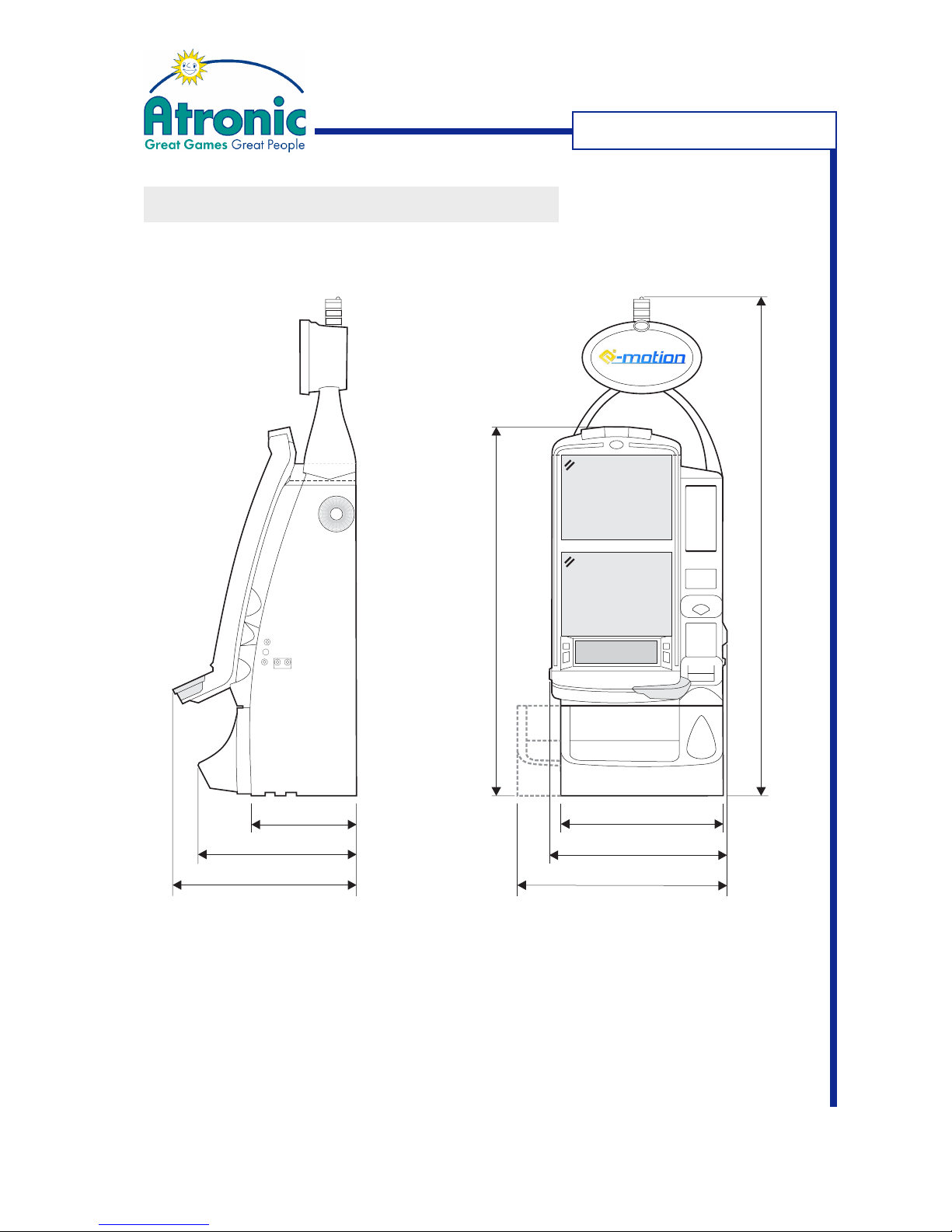
DIMENSIONS
D
IMENSIONS
540
632
1705 (mm)
1360
(Playfield in highest position)
550
607
700
360
Page 14
14
June 2008
e²-motion™ Installation Manual
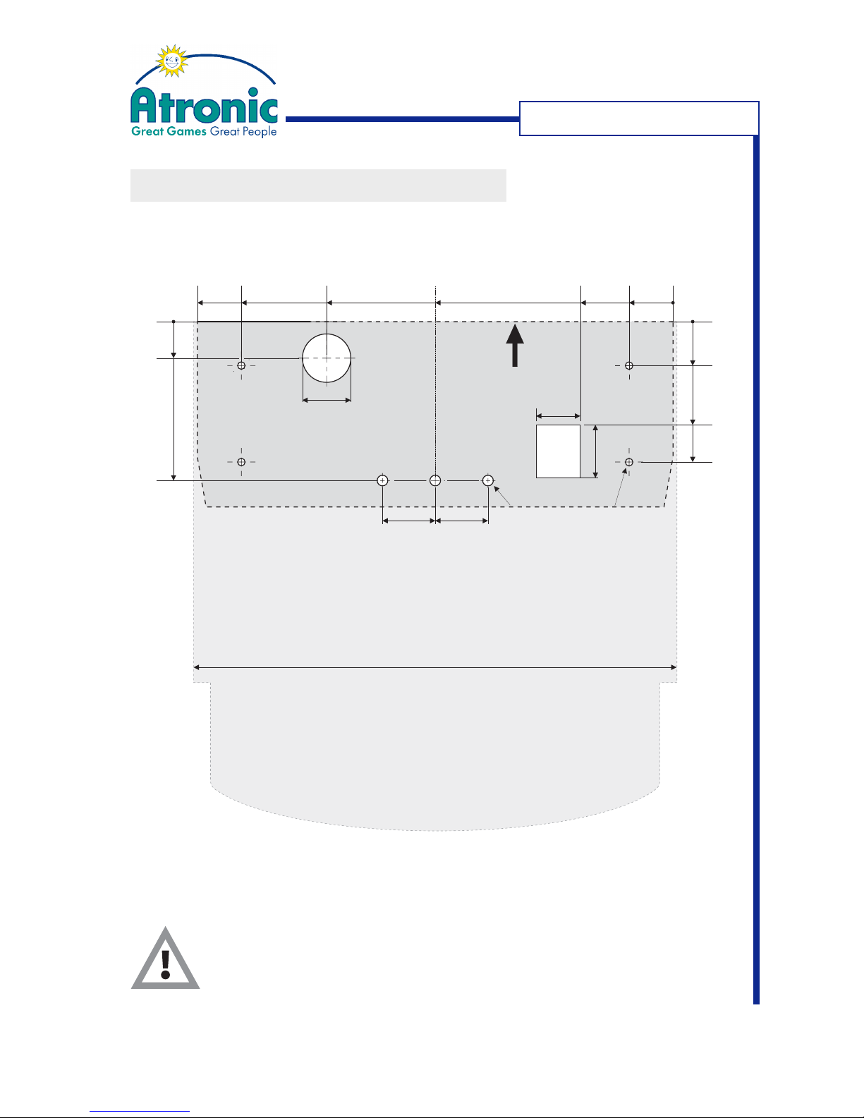
FOOTPRINT / DRILLING TEMPLATE
Make sure to leave min. 180mm (7.1") distance to the next machine or
a wall on both sides of the cabinet. Do not cover the ventilation slots
at both sides of the cabinet.
50
6060
55
60
50
Baseboard
Cabinet
Footprint
550
Ø10mm
Ø10mm
Backside
105.5
270.5
394
491
541
0
0
50
117.5
157
0
41.5
181
DIMENSIONS
Page 15

15
June 2008
e²-motion™ Installation Manual
Weight: approx. 114 kg (251 lbs)
Required Voltage: 100V to 240V AC,
50Hz / 60Hz,
use earthed power outlet
rated min. 8A.
Power Consumption: Idle Mode: approx. 200 Watt,
1.8A / 115V
0.9A / 230V
Payout Mode: approx. 300 Watt,
2.6A / 115V
1.3A / 230V
Max. Power: approx. 450 Watt
(Without internal power outlets)
Power Supply
Secondary Voltage: +24V / 5A
+12V / 17A
- 12V / 0.5A
+5V / 20A
+3.3V / 7A
Fuse Power Supply: F 8A / 250V
Fuses Filterboard: F2 (+12 V) = T 6.3A / 250V (UL fuse)
F3 (+24 V) = T 4A / 250V (UL fuse)
Environmental Specifications
Operating Temperature: 0°C - 45°C
(32°F - 113°F)
Operating Humidity: 0% to 85% (non condensing)
TECHNICAL DATA
T
ECHNICAL DATA
Page 16

16
June 2008
e²-motion™ Installation Manual
- blank page -
Page 17
17
June 2008
e²-motion™ Installation Manual
MACHINE INSTALLATION - OVERVIEW
This section should only be carried out by
qualified technical service personnel.
Review the list below and perform as needed.
Explanations are located on the following pages and
in additional manuals.
Inspect machines for transport damage. Any
transport damage should be noted and witnessed
by the freight forwarder. The manufacturer accepts
no responsibility for transport damage.
Check machines for the correct paytable, glasses,
hardware configuration and that software EPROMs
are correctly installed.
Prepare the base by drilling the mounting holes.
Use the Atronic drilling template for proper
mounting hole placement.
Place and mount the machine to the base, using
the Universal Corpus Baseboard (see next page).
Thread the power cable into the base. Do not
connect power to the machine.
Replace shipping locks with casino specific locks.
Install and connect accounting system.
Check that all internal and external connections
are seated correctly.
Prepare coin acceptor and hopper.
Apply power to the machine.
Load paper into the printer.
Execute basic machine setup (Initial Setup)
Configure game.
Test bill and coin handling.
MACHINE INSTALLATION
Note: Depending on machine
configuration or jurisdictional
requirements, additional tasks
may have to be carried out
before the machine can be put
into operation (e.g. acceptance
inspection, logicbox sealing,
etc.).
Page 18
18
June 2008
e²-motion™ Installation Manual
MACHINE INSTALLATION
Machine Mounting
Caution! Tipping Hazard
Do not operate the machine unless it
has been properly secured to the base.
The machine can tip over, if it is not
properly mounted to a solid base.
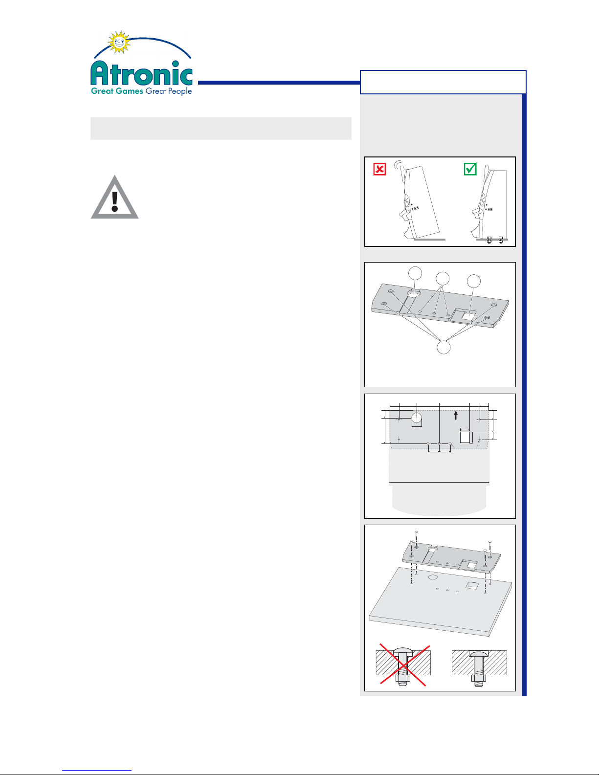
1. Use the baseboard, supplied by Atronic, to mark
the holes on the base before drilling. Make sure to
leave min. 180mm (7.1") distance to the next
machine (or a wall) on both sides of the cabinet.
During shipping the baseboard is mounted on the
bottom side of the machine. If the baseboard is
not yet at hand, use the footprint drawing on page
13 instead.
2. Drill four holes 10mm (
3
/8 ") for mounting the
baseboard (A).
3. Drill one out of the three 10mm (3/8") holes for the
machine securing bolt (D). It is not important which
one of the 3 holes is used. If the base has braces
or struttings placed below one mounting hole,
simply use another one.
4. Drill or cut out one 55mm (2¼") hole for threading
the mains cable into the base (B) and cut out the
60 x 50 mm coin drop recess (C)
5. Mount the Universal Corpus Baseboard to the base
using 4 mounting bolts and fasten with washer
and wingnuts.
Make sure that the boltheads are completely
lowered into the counterbores of the baseboard.
MACHINE INSTALLATION
A
B
C
D
Universal Corpus Baseboard
50
6060
55
60
50
Baseboard
Cabinet
Footprint
550
Ø10mm
Ø10mm
Backside
105.5
270.5
394
491
541
0
0
50
117.5
157
0
41.5
181
See also page 13 for footprint drawing
Page 19
19
June 2008
e²-motion™ Installation Manual
MACHINE INSTALLATION
Machine Mounting (continued)
Caution!
The machine weighs approx. 114 kg.
If available, use a lift truck.
Make sure that the mains power cable is
completely inside the cabinet and not
threaded through the lower AC hole, before
sliding the machine onto the baseboard!
Otherwise the cable will be damaged!
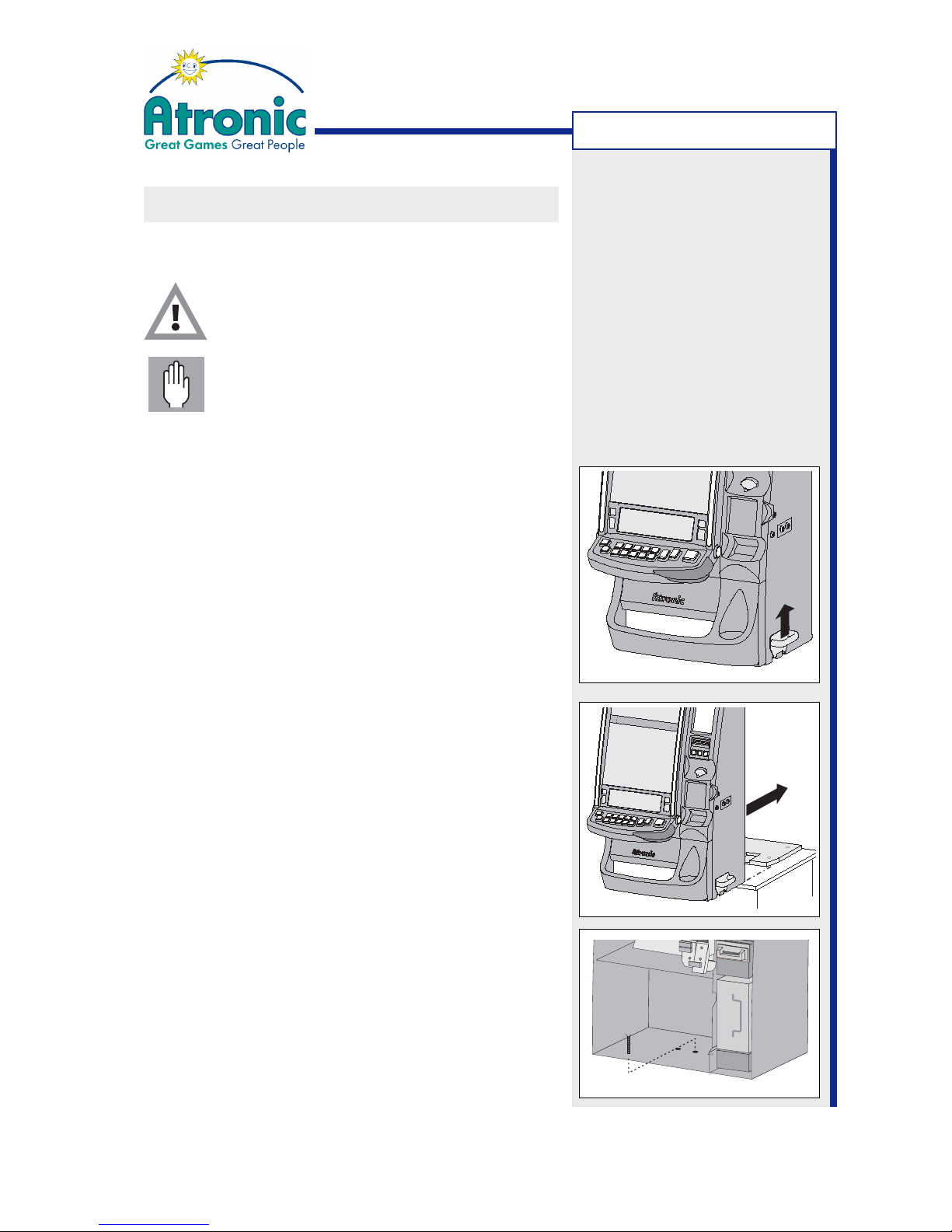
6. Before lifting make sure that the mains power cable is completely inside the machine and that hopper drawer and maindoor are closed and locked.
7. Hook the two carry handles into the handle receptacles at both sides of the cabinet.
8. Lift the machine and then slide it onto the mounted baseboard. The cabinet will grasp into the guides of the baseboard.
9. Carefully slide out the hopper drawer and mount
the securing bolt to secure the machine to the
base stand. Fix the securing bolt with washer and
wingnut.
It is not important which of the 3 holes is used, if
at least one securing bolt is mounted. If the base
stand has braces or struttings placed below one
of the mounting holes, simply use another one.
MACHINE INSTALLATION
Page 20
20
June 2008
e²-motion™ Installation Manual
MACHINE INSTALLATION
Topper Mounting (optional)
The optional machine toppers are delivered seperately.
They have to be mounted and connected.
Note: Toppers with a progressive display use an additional power supply not described in this manual.
Please refer to the relevant mounting instructions.
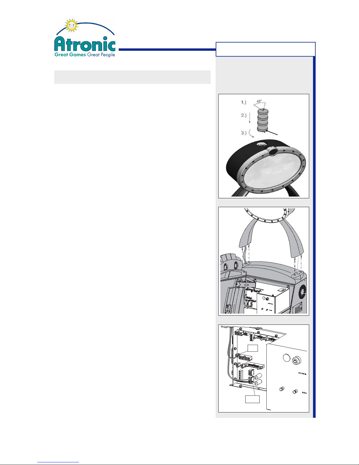
1. Connect and mount the toplight to the topper as
illustrated.
To avoid damaging, hold the toplight at its lower
ring, when you screw it into the topper bayonet
catch.
2. Thread the connecting cables and the earthing cable into the cabinet and position the topper onto
the cabinet.
3. Fix the topper with 4 knurled nuts.
4. Connect the earthing cable to the earthing stud
on the upper right inside the cabinet. Make sure
that the earthing has good contact and fix it with
a nut with lockwasher.
5. Connect the topper cable labled 65049935 to the
filterboard signal, connector P14.
6. Connect the topper cable labled 65049939 to the
filterboard signal, connector P6.
MACHINE INSTALLATION
Hold here
P14
P6
Page 21
21
June 2008
e²-motion™ Installation Manual
MACHINE INSTALLATION
Replace shipping locks
if not ordered otherwise, Atronic machines are
equipped with shipping locks for easy commisioning.
These locks have to be replaced by casino specific
locks to provide appropriate security.
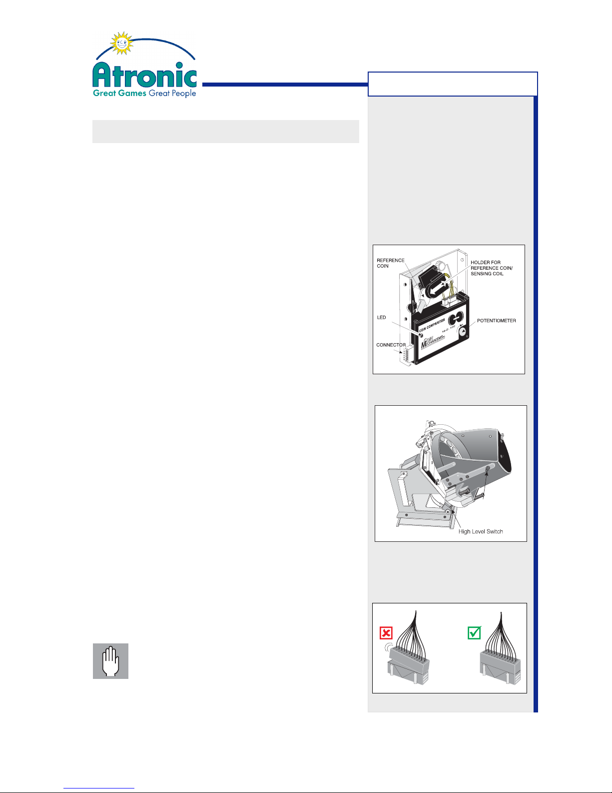
Prepare Coin Acceptor (MC-16)
• Slide holder for reference coin rightwards, remove
(plastic) transport chip and replace it with appropriate reference coin.
• Check reference coin for proper (parallel) seating.
-> See manuals Peripherals / Coin Acceptor for details.
Prepare Hopper
The hopper high level switch detects the filling level
of the hopper by the weight of the coins. If the switch
is activated, further accepted coins are separated to
the drop box. The switching threshold can be altered
with an adjustment srew.
• Fill the hopper with that amount of coins/tokens at
which you want the switch to be activated.
• Adjust switching threshold with the adjustment
screw that operates the high level switch.
-> See manuals Peripherals / Hopper for details.
Check cables and connectors
Check that all connectors are seated correctly, prior
to first power up.
False or loose connections can cause irreparable damage, not covered by
warranty.
MACHINE INSTALLATION
Page 22
22
June 2008
e²-motion™ Installation Manual
MACHINE INSTALLATION
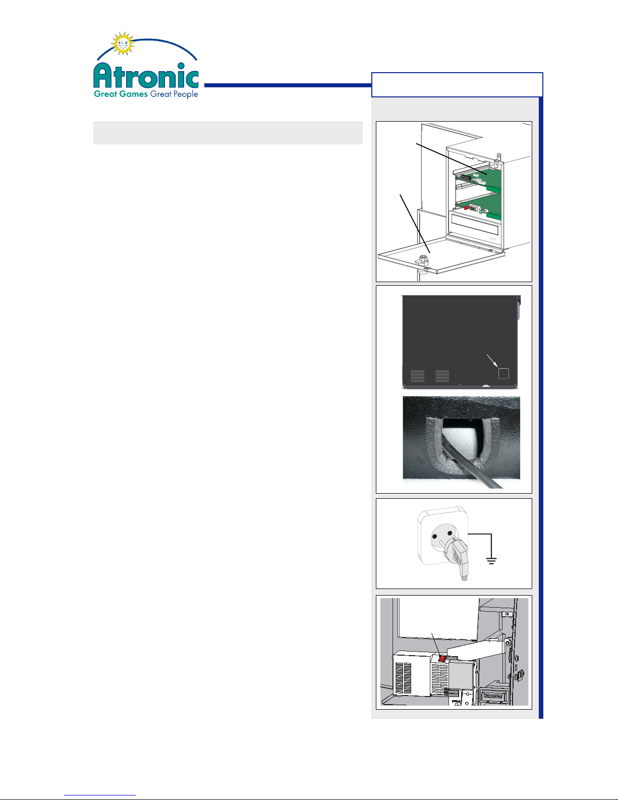
Check Commboard Settings
The commboard DIP switches and rotary switches
configure SAS address, APL address, progressive
mode and SAS (dual) channel allocation.
Use the DIP switch tables within manual "Software /
Basic Setup" for a particular software version (e.g.
C5.1.x) to check or alter the commboard settings.
Then connect to the online system components.
Apply Power
• Punch out one of the perforated knock-out plates
in order to provide access for the power cable (figure a).
• Mount the enclosed edge protection (figure b).
• Check that the machine mains cable has not been
damaged during transit.
• Check that the supply socket is in good condition
and not showing any signs of overheating or damage.
• Connect the power cable to a grounded power outlet, that is rated for min. 3A / 230V at 50 Hz or
6A / 115V at 60 Hz.
• Switch the machine on and check that the machine initializes. The LED's on the masterboard (they
indicate correct voltages) should all be lit. The power switch is located at the power supply left to
the hopper.
Note: The power up cycle will take some minutes,
because the machine checks installed hardware
and security relevant circuits. To operate the machine while the maindoor is open, pull the maindoor
switch (set it to closed position).
MACHINE INSTALLATION
Power Switch
Commboard
Logicbox
Cover
(a)
(b)
At this point the machine installation is finished. Proceed
with Basic Setup. (Initial Setup and Service Menu settings)
Please refer to the software manual for a particular software
version for details, e.g. Manual HI Software (C5.x.x.x STD)
Page 23

23
June 2008
e²-motion™ Installation Manual
BASIC SETUP
Atronic machines usually come configured as specified
during order processing. However it might be
necessary to reconfigure basic machine settings,
such as denomination, metering, paytable, etc. These settings can not be altered during normal
operation, as they require a machine re-initialization
for technical or jurisdictional reasons.
Note: Please refer to the document "Manual HI Software (version)" relevant for a particular software
version (e.g. C5.1.x.x) for detailed information.
1. Configure the Commboard
This is necessary only, if you have to alter the commboard settings, such as progressive mode or channel allocation.
2. Carry out a RAM Reset (incl. Commboard Clear)
This will clear all machine data, statistics and settings, including progressive jackpot configuration.
3. Carry out the Initial Setup
After a RAM Reset the machine automatically enters the Initial Setup menu. The Initial Setup allows to configure all basic machine setting.
4. Carry out Progressive Jackpot Configuration
A PC or notebook with Atronic's Alink Config software is connected to the gaming machine and
uploads the progressive jackpot configuration data.
Important: It is necessary to carry out the progressive jackpot configuration directly after the
Initial Setup. Do not insert credits before the jackpot configuration data is uploaded.
In an Atronic Progressive Link™ (APL) the jackpot
configuration has to be carried out at the APL master machine only. The jackpot configuration data is
then transferred to all linked APL slave machines.
5. Adjust game settings in the Service Menu
BASIC SETUP
Page 24

24
June 2008
e²-motion™ Installation Manual
TESTS
Test Bill and Coin Handling
Open maindoor and press the Service button at front
of the logic box. The Service Menu is displayed. Select
file tab Diagnostics.
• Test coin handling.
-> / Coin Acceptor / Optics Test
• Test coin diverter.
-> / Coin Acceptor / Coin Diverter
• Test bill acceptor
-> / Bill Acceptor / Validator Test without Stacking
• Test hopper payout and switching times
-> / Hopper / Pay out x coins
Note: Please refer to the document "Manual HI Software (version)" relevant for a particular software
version (e.g. C5.1.x.x) for detailed information.
Note:
Make sure to have stacker lock
keys and the cashbox keys at
your hands, when performing
a "Validator Test with Stacking".
TESTS
Page 25

25
June 2008
e²-motion™ Installation Manual
TECHNICAL SUPPORT
TECHNICAL SUPPORT TELEPHONE NUMBERS
Atronic offers and provides technical support 24 hours a day, 7 days a week.
If technical assistance is required during normal business hours, please contact
your local technical services representative at one of the numbers below.
Technical Support Locations:
Atronic Germany (International Headquarter) (+49) 5741 273 720
Atronic Peru (+51) 161 832 00
Atronic United Kingdom (+44) 1727 855 966
Atronic Russia (+7) 495 737 72 99
If technical assistance is required outside of normal business hours, please contact
the Atronic Technical Hotline number below.
Atronic Technical Hotline:
For technical assistance in Europe,
South Africa, Asia, Central and South America
outside of normal business hours: (+49) 5741 273 777
 Loading...