

Page 1
DUPLEX Easy
Compact ventilation units
with heat recovery and EC fans
Intended use
The new heat recovery units DUPLEX Easy are supplied in
three sizes:
=
DUPLEX 250 Easy
=
DUPLEX 300 Easy
=
DUPLEX 400 Easy
The units are intended for the comfort ventilation of all types of
residential and civil premises. They are particularly suitable for
low-energy and passive houses and flats in apartment buildings
with a decentralized ventilation system.
General description
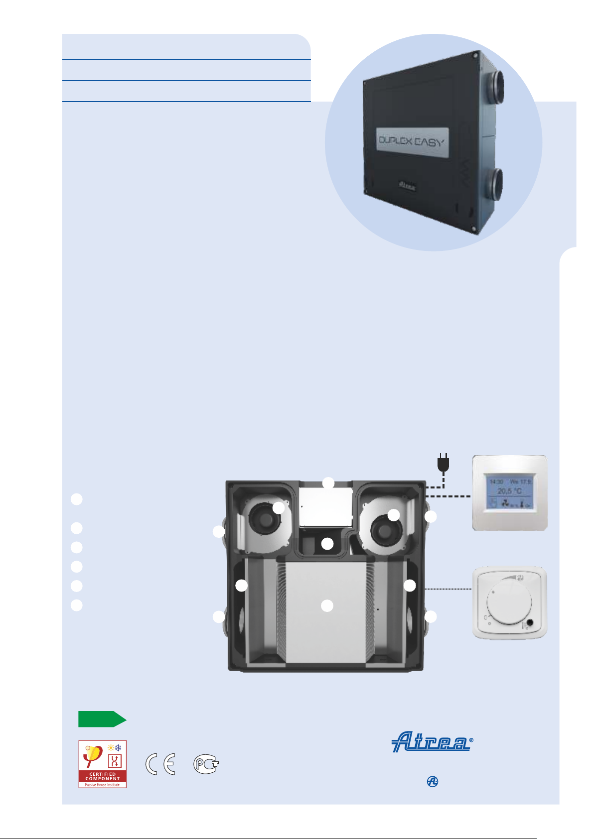
The casing of the unit is made of environmentally friendly EPP
(expanded polypropylene), which is also characterized
byminimal moisture absorption and stability over a wide range
of temperatures. The basic version of DUPLEX Easy unit
consist of EPP housing, counter-flow heat exchanger made
ofplastic (efficiency up to 93 %), two free wheel type fans with
electronic EC control, G4 (optionally F7) supply and exhaust air
filters upstream the heat recovery exchanger. Depending the
type oncontrol system, the unit can be equipped with several
different functions and accessories (see the chart on page 4).
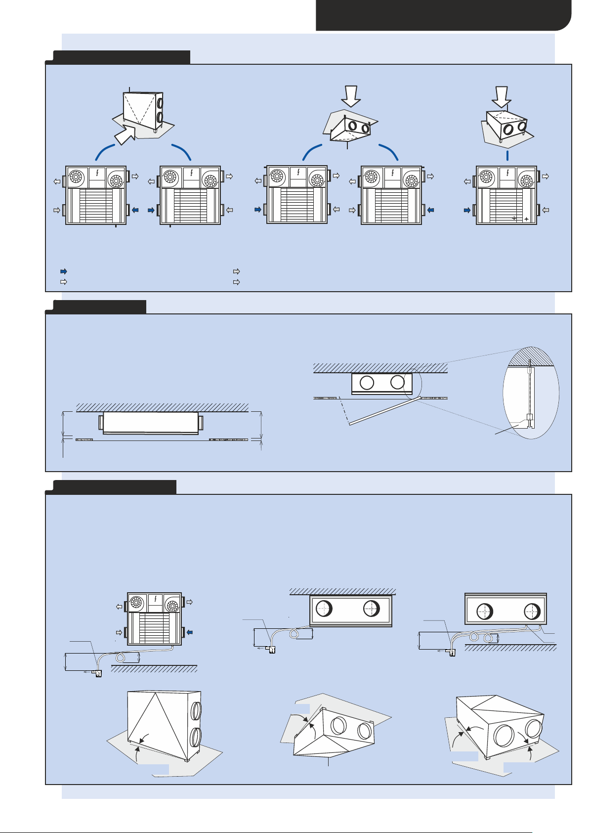
The Construction of the unit provides high variability, and the
same unit can be installed in 5 different positions (2 floorstanding, 2underceiling and 1 floor-standing flat). Condensate
outlets on DUPLEX Easy are ready for all possible mounting
positions. Connecting ports are of a circular type for flexible
orrigid ducts with thermal bridging reduction.
C
ounter-flow heat exchanger
1
with efficiency up to 93 %
EC fans
2
Bypass damper with actuator
3
Air filters G4 or F7
4
Circular port
5
EPP housing
6
5
4
2
5
Advantages of DUPLEX Easy units
=
High efficient EC fans
=
High heat recovery efficiency of the counter flow heat
exchanger
=
Great thermal and mechanical parameters of the housing
=
Very flat unit (280 mm) suitable for underceiling
installation
=
An option of the mirror-wise change of the right hand /
left hand side position
=
Light weight of the unit
=
Ease of filter changing
=
Frost protection (optionally built-in)
=
Bypass with actuator (optionally built-in)
=
Four types of control systems (see page 4)
6
2
3
5
touch screen
controller CPA (CS2)
4
alter.
1
5
D U P L E X E A S Y
controller CPB (CS1)
Residential ventilation and heating – issue 01/2016
A
R E S I D E N T I A L V E N T I L A T I O N & H E A T I N G
ATREA s.r.o., Čs. armády 32
466 05 J ablon ec n. Niso u
Cze ch Re pub lic
w w w . a t r e a . e u
Tel.: +420 483 368 111
Fax: +420 483 368 112
E- mail : at rea @at rea. eu
Page 2
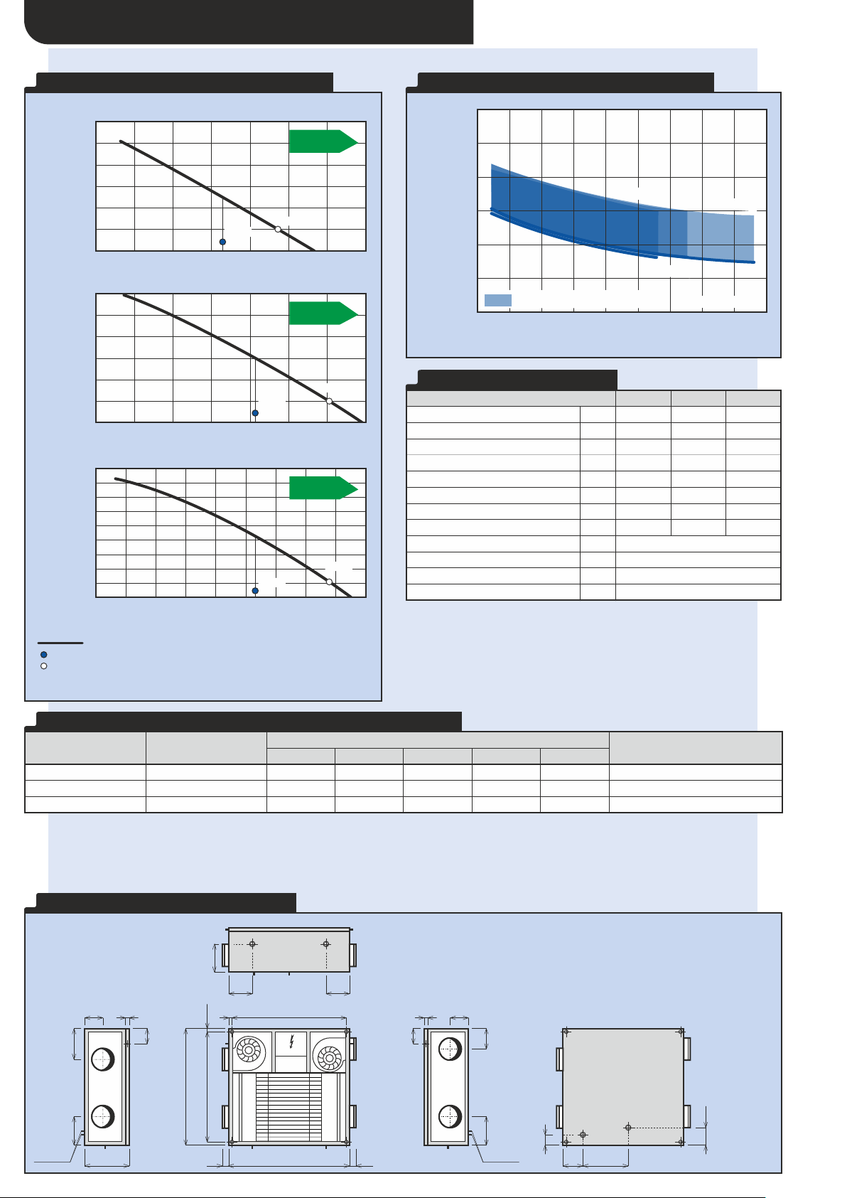
TECHNICAL DATA – DUPLEX EASY
DUPLEX Easy
250
300
400
Supply air – max.
3
m /h
280
330
430
Extract air – max.
3
m /h
280
330
430
Max. heat recovery efficiency
%
93
93
93
Max. power consumption of fans
W
120
120
220
Width B
mm
660
820
820
Dimension D
mm
425
435
435
Diameter of connecting ports
mm
160
160
160
Weight
kg
202121
By-pass
–
optional
VoltageV230 / 50 Hz
Supply air filter class
–
G4 (alter. F7)
Condensate drain
mm
6x 14 (depending on position)
Type
Working point
Acoustic power L [dB(A)]
w
Acoustic pressure L [dB(A)]
p
at distance of 3 m
inlet e1inlet i
1
outlet e
2
outlet i2unit
DUPLEX 250 Easy
3
200 m /h (100 Pa)
535374*
74*
60 / 54**
40 / 33**
DUPLEX 300 Easy
3
250 m /h (100 Pa)
515174*
74*
61 / 54**
40 / 34**
DUPLEX 400 Easy
3
300 m /h (100 Pa)
505075*
75*
62 / 55**
42 / 35**
P E R F O R M A N C E P A R A M E T E R S E A S Y
D U P L E X 2 5 0 E A S Y
600
500
st
A
400
300
200
100
Pressure reserve p (Pa)
0
0 150 200
10050
48 W
112 W
300250 350
D U P L E X 3 0 0 E A S Y
600
500
st
A
400
300
200
100
Pressure reserve p (Pa)
0
0 150 200
10050
58 W
126 W
300250 350
D U P L E X 4 0 0 E A S Y
900
800
st
700
A
600
500
400
300
200
100
0
Pressure reserve p (Pa)
0 150 200
10050
87 W
300250 450
Volume flow rate (m /h)
Legend:
Pressure reserve with filter G4*
Qref Reference flow rate
Qmax Maximum flow rate
* Max. pressure reserve curve is shown
* Electrical power consumption is shown (both fans and control system)
218 W
350 400
3
H E A T R E C O V E R Y E F F I C I E N C Y E A S Y
100
95
Heat recovery efficiency (%)
90
85
80
75
Possible condensation region
70
0
50
100 200 250 350300 400 450
150
250
Easy
300 Easy
400
M = M
i e
Volume flow rate (m /h)
T E C H N I C A L D A T A E A S Y
1)
All types of control system that are built in within the unit commonly include at
least two inputs, so the electrical signals from human operation of lights or other
equipment, that automatically control the performance of the unit, can be
connected. These inputs or other types of sensors must always be connected
(e.g. CO , VOC, rH etc.)
2
2)
Maximum flow rate at 100 Pa
3)
The value is at reference flow rate it means 70 % of maximum flow rate
and50Pa
4)
Acoustic values of the units with SK cover – see accessories
Easy
3
A C O U S T I C P O W E R L A N D A C O U S T I C P R E S S U R E L
To achieve acceptable acoustic values it is necessary to install air distribution with guaranteed acoustic attenuation.
* Approximately it is possible to reduce sound power on outlet e , i to following values:
=
L = 52 dB (A) – using 1 m of soundproofed pipe
w
=
L = 43 dB (A) – using 2 m of soundproofed pipe
w
=
L = 37 dB (A) – using 3 m of soundproofed pipe
w
** Acoustic values of the units with SK cover – see accessories
W P
2 2
D I M E N S I O N A L D I A G R A M E A S Y
K2K2
K1 K1
K3
165
22,5
K4
165
805
CM
K1 K1 K1
850
4545
100
20
210
190
K3, K4
280
80
K2
K1
198
22,5B - 45
K2 K2
B
K1 ... Condensate drain for floor-standing position
K2 ... Condensate drain for underceiling position
K3 ... Condensate drain for floor-standing flat position
K4 ... Condensate drain for floor-standing flat position
* For both floor-standing and underceiling position use only one appropriate
condensate drain.
** For floor-standing flat use both condensate drains.
100
20
80
K2
135
190
K3, K4
65
120
K3
K4
90
D
Page 3
M O U N T I N G P O S I T I O N S
X
Hmin. 25
12
DUPLEX Easy
e
1
e
2
i
2
i
1
RM
min. 150
min. 150
HL 21
Inlet into
sewer
K1
min 150
min 150
HL 21
Inlet into
sewer
K2
min. 150
HL 21
Inlet into
sewer
min. 150
K3
K4
F L O OR -S TA ND IN G U N D ER CE IL IN G F L O OR -S TA ND IN G F LA T
DUPLEX EASY
K2
i
2
e
2
i
1
RM
K1 K1
i
2
e
e
1
1
RM
e
2
i
2
e
i
1
1
RM
e
2
e
2
i
i
1
1
RM
K2
e
e
i
i
2
1
2
e
1
RM
2
i
1
K3K4
Note: DUPLEX Easy units are supplied for versatile position mounting – the unit can be installed in all positions (floor-standing, underceiling and floor-standing
flat). The ”right hand” and ”left hand” position according to the figure above is selected simply by relocating the operating sensor and by reconnecting unit fans.
L E G E N D
e Fresh outdoor air suction
1
e Fresh filtered air outlet
2
I N S T A L L A T I O N
i Exhaust air suction
1
i Exhaust air outlet
2
CM Control module
DUPLEX Easy – underceiling position
New DUPLEX Easy units have a very flat design that allows installing
them into even very low suspended ceilings. The minimum
requirements for suspended ceiling void height is 305 mm.
A plasterboard lid is fitted below the unit.
removable door
C O N D E N S A T E D R A I N
Condensate drainage
During heat recovery – heat regaining – moisture is condensated during the cooling of exhaust air. Water condensates on the walls of the
heat recovery exchanger, further increasing heat recovery efficiency. Condensate runs out of the heat recovery exchanger in the direction
of air being extracted and is drained from the DUPLEX unit into a sewer system. For correct functioning and drainage the unit must be
separated from the sewer system using a siphon of asufficient height, the recommended minimum being 150 mm. Small condensation
drain pumps may be used. The unit must be installed within the specified gradient for each position.
F L O OR -S TA ND IN G U N D ER CE IL IN G
i
2
3° = 25 mm
i
2
F L O OR -S TA ND IN G F LA T
i
1
10° = 75 mm
3° = 25 mm
12° = 100 mm
Page 4
CONTROLS
D
(mm)
Voltage
(V)
Power input
(kW)
EPO-PTC 160 / 0,4 kW
160
1x 230 V
~
0,4
EPO-PTC 160 / 0,7 kW
160
1x 230 V
~
0,7
EPO-PTC 160 / 1,7 kW
160
1x 230 V
~
1,7
SK / 250
Special two-piece cover made of galvanized metal sheet (silver color) for better
acoustic parameters
of the DUPLEX Easy.
SK / 300
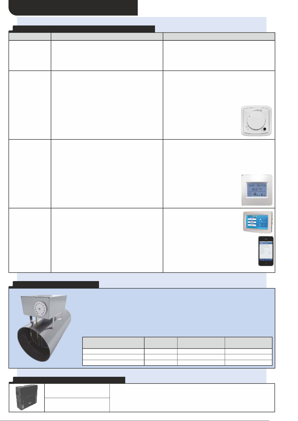
S U M M A R Y O F D U P L E X E A S Y C O N T R O L S Y S T E M S
Type Description Controller
=
„Without control
system“
All electrical components are wired to a junction box
inside the unit. This solution is suitable for applications
with computer-based control system (BMS) installed in
buildings that controls and monitors the building’s
mechanical and electrical equipment.
Without controller
=
Frost protection – fan disballance
=
Automatic by-pass with servo drive
“CS1“ controls
“CS2“ controls
“RD5“ controls
This is the starting level of the DUPLEX Easy control
system that gives basic functions of controlling of the
unit. CS1 version comes with an installed controller.
This version meets higher requirements and is fully
ready for modern comfort living. This level of our control
system comes with a touch screen controller.
This ATREA proprietary control system meets all
requirements for high-demand controlled ventilation.
The great advantage is the integrated web server as
standard.
=
Volume flow
=
Frost protection – preheater (EPO-PTC) or fan
disballance
=
Reheating (EPO-PTC)
=
Automatic by-pass with servo drive
=
Analogue input (0–10 V) for air quality sensor
=
Minimum and maximum
speed preselection
=
Inlet and outlet shut-off damper
control
=
Automatic or manual mode
=
Frost protection – preheater (EPO-PTC) or fan
disballance
=
Reheating (EPO-PTC)
=
Analogue input (0–10 V) for air quality sensor
=
Inlet and outlet shut-off damper control
=
Manual or weekly program
=
Room temperature display
=
Party mode, holiday mode
=
Filter change notice
=
Minimum and maximum
speed preselection
=
Frost protection – preheating
(EPO-PTC) or fan disballance
=
Optional constant flow function
=
Modbus TCP
=
Analogue / digital input
=
Right or left configuration just through
the controller setting
=
Weekly programming
=
A ventilation run-down and delay time option
=
Boost and party mode
=
Combined heating and preheating (EPO-PTC) –
electrical or water based
E L E C T R I C H E A T E R S E P O - P T C
• Used as a preheater to preheat fresh air, to be
installed in ducts on fresh air inlet
• Used as an afterheater to reheat supply air, to
be installed in ducts after the unit
• Integrated PTC (Positive Temperature
Coefficient) heating elements
• Housing includes a terminal board
and internal wiring
O P T I O N A L A C C E S S O R I E S – S K C O V E R
• Includes two protection thermostats –
areversible one and a safety irreversible one
• Contains an interference-free SSR relay
asstandard
• Perforated metal filter to protect heater from
gross particles (easily cleanable)
• Galvanized sheet metal housing
 Loading...