

Page 1

Revision:
01
Revision Date:
2016/01/11
AX9
User Manual
ATrack Technology Inc.
3F., No. 88, Sec. 1, Neihu Rd., Neihu Dist.,
Taipei City 11493, Taiwan (R.O.C.)
Tel: +886-2-27975852
Fax: +886-2-27974030
http://www.atrack.com.tw
Page 2

Confidential Document
Table of Contents
1. Notification .............................................................................................................................. 3
1.1. Disclaimer .................................................................................................................................... 3
1.2. Copyright ...................................................................................................................................... 3
1.3. Warning ........................................................................................................................................ 3
2. Introduction ............................................................................................................................. 4
3. Installation ............................................................................................................................... 5
3.1. Package Content ......................................................................................................................... 5
3.2. AX9 OBD-II Compliant ................................................................................................................. 5
4. Hardware Features ................................................................................................................. 6
4.1. OBD-II Protocol ............................................................................................................................ 6
4.2. Mini USB Port and Driver Installation........................................................................................... 6
4.3. Buzzer Operation ......................................................................................................................... 7
4.4. Power Supply ............................................................................................................................... 7
4.5. SIM Card Installation .................................................................................................................... 8
4.6. LED Indicators ............................................................................................................................. 9
5. Configuration ........................................................................................................................ 10
5.1. Connecting a Device Using HyperTerminal ............................................................................... 10
5.2. Connecting a Device Using AXTool ........................................................................................... 14
5.3. Firmware Upgrade ..................................................................................................................... 19
6. Bluetooth Applications ......................................................................................................... 20
6.1. Using an Android Mobile to Connect to your AX9 ...................................................................... 20
6.2. Using a PC to connect to your AX9 ........................................................................................... 21
6.3. Bluetooth Commands ................................................................................................................ 24
7. Appendix ................................................................................................................................ 25
7.1. FCC Regulations ........................................................................................................................ 25
7.2. Hardware Specification .............................................................................................................. 26
© ATrack Technology Inc. All Rights Reserved. Page 2 of 27
Page 3

11.. NNoottiiffiiccaattiioonn
11..11.. DDiissccllaaiimmeerr
11..22.. CCooppyyrriigghhtt
11..33.. WWaarrnniinngg
Confidential Document
This document, and all other related products, including device, firmware, and software, are exclusively
developed by ATrack Technology Inc. Due to the continuous developments and improvements of device
functionalities, changes in the protocol, specification, and firmware functions are subjects to change without
notice. ATrack Technology Inc. reserves the right to modify all documentations based on its own timelines.
Document modification notices will be released to ATrack Technology Inc.’s customers upon completion.
ATrack Technology Inc. products are not intended to be used as life support or rescue equipments. ATrack
Technology Inc. is not liable for any loss or injury caused by using or referencing to any of its products. Any
possible means of using or integrating ATrack Technology Inc. products shall be avoided.
ATrack Technology Inc. holds all parts of intellectual rights applicable in the copyright laws in all the countries.
Any and all contents of this document shall not be exposed, delivered, and/or disclosed to non-authorized 3rd
party without any form of approval and consent from ATrack Technology Inc. Any form of, including but not
limited to, verbal, duplicate, or internet sharing, of releasing or exposing information to an unauthorized party
shall be prohibited. ATrack Technology Inc. reserves the rights of litigation in the violation of copyright laws.
Connecting of the input wires can be hazardous to both the installer and your vehicle’s electrical system if not
done by an inexperienced installer. This document assumes you are aware of the inherent dangers of working
in and around a vehicle and have a working qualified understanding of electrical behaviors.
© ATrack Technology Inc. All Rights Reserved. Page 3 of 27
Page 4
22.. IInnttrroodduuccttiioonn
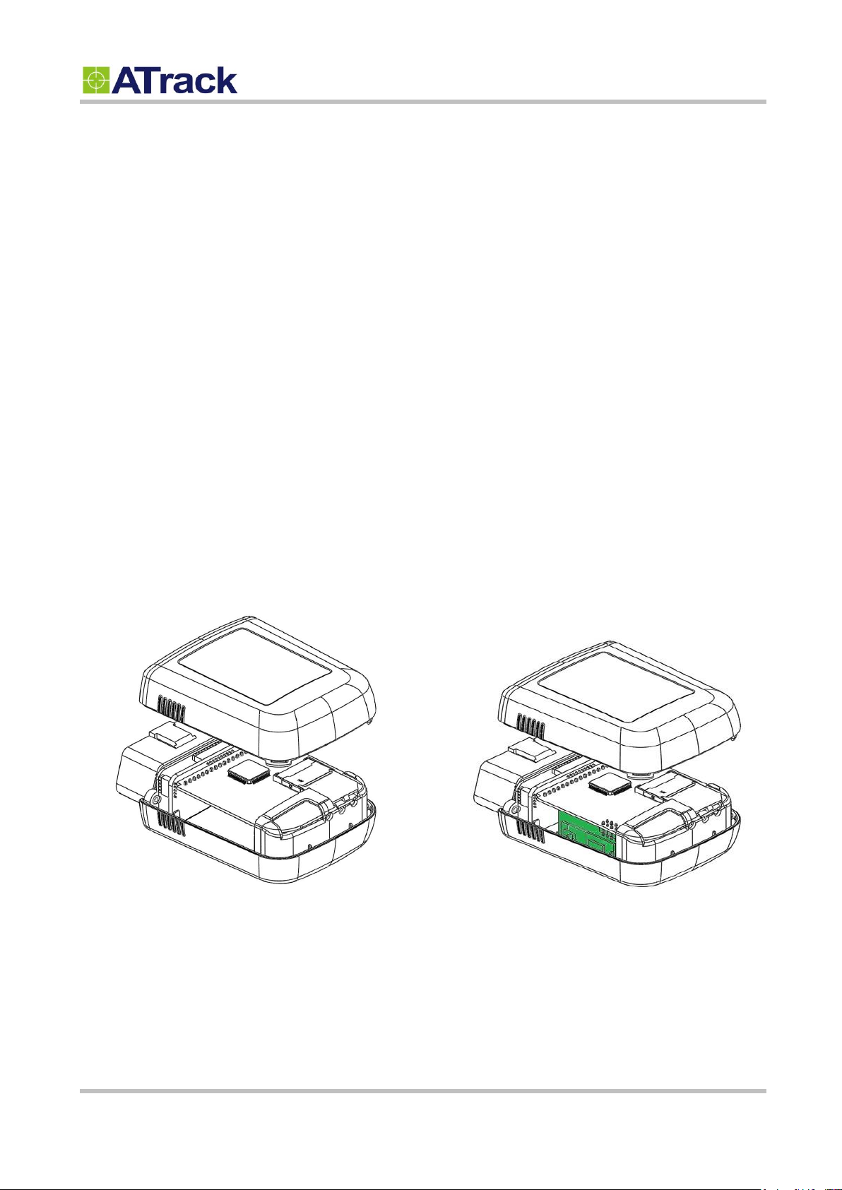
The AX9 without Bluetooth module
The AX9 with Bluetooth module
Confidential Document
Congratulations on your purchase of the ATrack AX9 GPS device, combining with the most comprehensive
and economical vehicle diagnostics technology, which provides real-time engine monitoring. The engine
diagnostic data is collected through the vehicle's OBD-II communication port and is transmitted along with
GPS data to the control center over a mobile network, for instance, GSM, GPRS, UMTS or CDMA. In this way,
potential engine problems can be identified earlier before the vehicle breaks down at an inopportune time.
Furthermore, you may configure other advanced driving behavior events such as harsh braking, sudden
acceleration, speeding, cornering, and much more in order to reduce the risks of vehicle damage and drive
down the costs of fuel.
Depending on your needs, the AX9 will come with an embedded Bluetooth module (refer to Chapter 6 for
more information). This user manual is intended to guide you through the installation and configuration
process. It also highlights the hardware features and Bluetooth applications.
© ATrack Technology Inc. All Rights Reserved. Page 4 of 27
Page 5
33.. IInnssttaallllaattiioonn
33..11.. PPaacckkaaggee CCoonntteenntt
33..22.. AAXX99 OOBBDD--IIII CCoommpplliiaanntt
Confidential Document
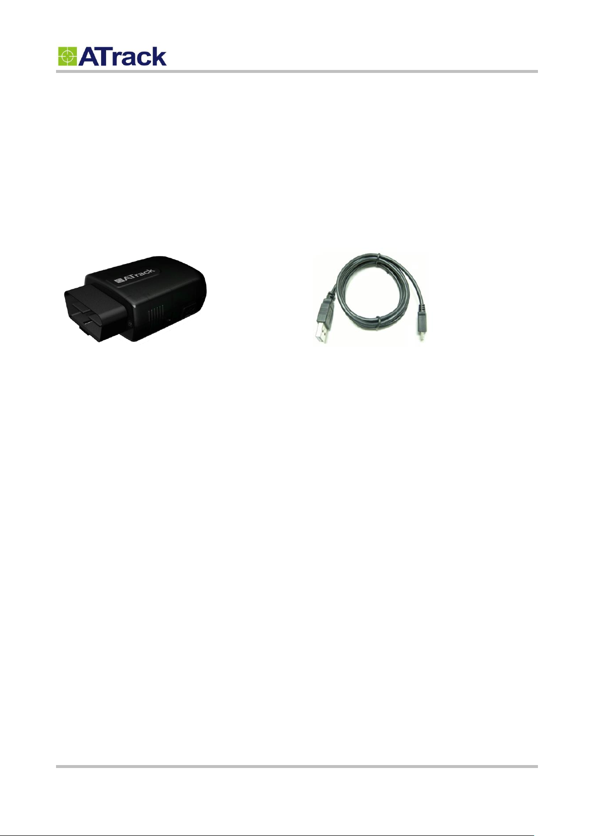
When you open the package, verify that you received the following:
AX9 Device * 1
USB Cable * 1
OBD-II is a set of standards and practices defined by SAE (Society of Automotive Engineers) in the early 1990s. But
some automobile manufactures do not follow it completely. Therefore, ATrack cannot guarantee each vehicle’s
OBD-II connected performance. For more information about the AX9 OBD-II compliance, please refer to the “ATrack
AX Series OBD-II Compliant Guide” document for details.
© ATrack Technology Inc. All Rights Reserved. Page 5 of 27
Page 6
44.. HHaarrddwwaarree FFeeaattuurreess
44..11.. OOBBDD--IIII PPrroottooccooll
44..22.. MMiinnii UUSSBB PPoorrtt aanndd DDrriivveerr IInnssttaallllaattiioonn
USB Port
USB Port
Confidential Document
There are five signaling protocols that are permitted with the OBD-II interface. Most vehicles have been
implemented with only one of the protocols. The AX9 features a superior protocol detection algorithm that ensures
the device connects reliably even to vehicles that do not fully conform to the OBD‐II standards. The AX9 supports
the following legislated OBD-II protocols:
J1850 PWM (Ford vehicles)
J1850 VPW (GM vehicles)
ISO9141-2 (Asian, European, Chrysler vehicles)
ISO 14230-4 KWP
ISO 15765-4 CAN (11/29 bit ID,250/500 Kbaud)
The AXTool provides the “OBD Live Data” viewer for showing OBD data in real time. Refer to Section 5.2 for details.
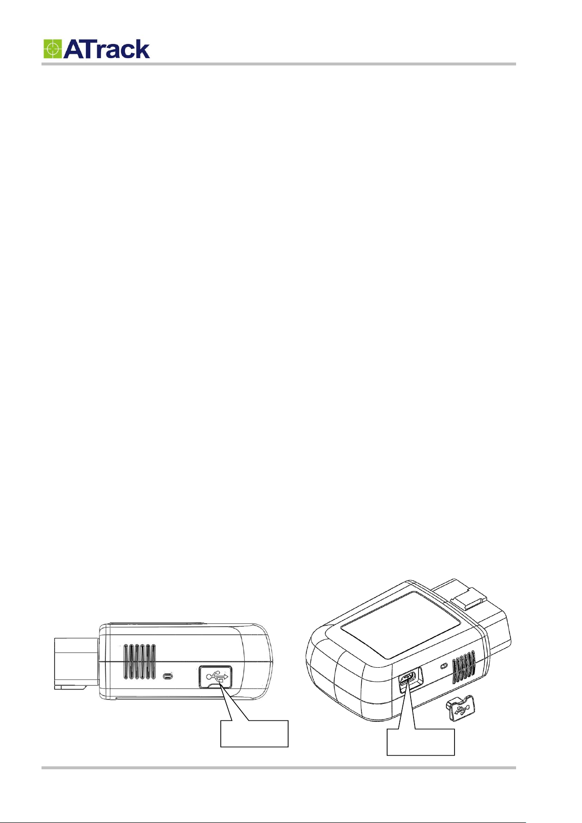
The Mini USB connection is used for the following purposes: configuring parameters and firmware upgrade. When
the AX9 is connected to your laptop/PC via a Mini USB cable, the OBD-II and GSM/GPRS functions are switched off
unless the main power is applied to the AX9 at the same time. The following figure shows the position of AX9’s USB
port.
© ATrack Technology Inc. All Rights Reserved. Page 6 of 27
Page 7
44..33.. BBuuzzzzeerr OOppeerraattiioonn
Buzzer Indication
Description
Beep 1 time
Device Power ON
Beep 2 times
OBD Protocol Connected
Beep 3 times
GSM/GPRS Connected
Beep 4 times
GPS Fix
44..44.. PPoowweerr SSuuppppllyy
Confidential Document
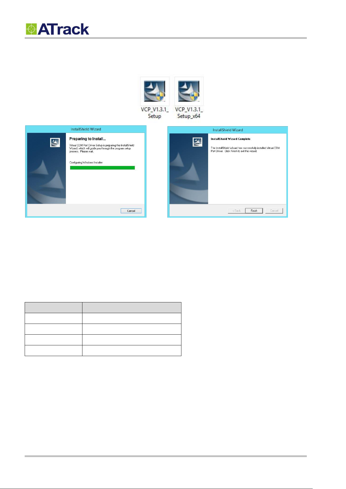
Double click the USB driver VCP_V1.3.1_Setup/ VCP_V1.3.1_Setup_x64. Then, click the Finish button to complete
the process.
The internal buzzer of the AX9 can be configured by any events or triggered by a remote server. Refer to the ATrack
Protocol Document for details. When a device is configured and plugged into an OBD-II DLC connector, it performs
some basic function tests. You can simply verify whether it is installed properly via buzzer indication. Please refer to
the following table for details:
The AX9 device is connected to the OBD-II SAE J1962 connector of a vehicle and draws power from the OBD port.
No additional power cabling is required for the operation. If the OBD port of a vehicle is covered or you need to
install AX9 in another place for better GPS reception, the optional low profile OBD-II extension cable is required.
© ATrack Technology Inc. All Rights Reserved. Page 7 of 27
Page 8
44..55.. SSIIMM CCaarrdd IInnssttaallllaattiioonn
Confidential Document
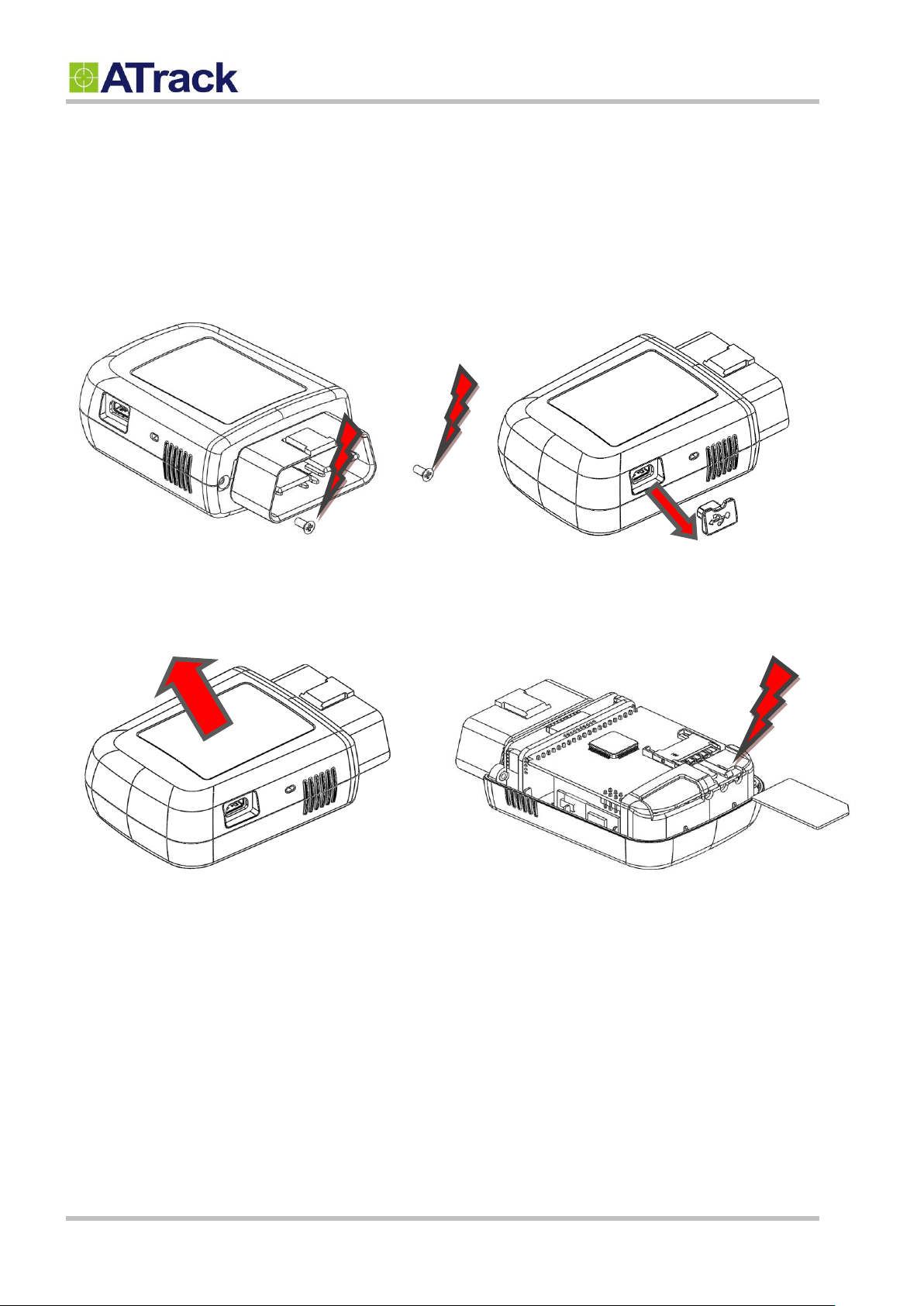
AX9 supports SIM cards with 1.8V (ISO/IEC 7816-3 class C) or 3V (ISO/IEC 7816-3 class B) operating voltages. To
install s SIM, remove the crews, dust cap and the cover.
(1) (2)
(3) (4)
© ATrack Technology Inc. All Rights Reserved. Page 8 of 27
Page 9
44..66.. LLEEDD IInnddiiccaattoorrss
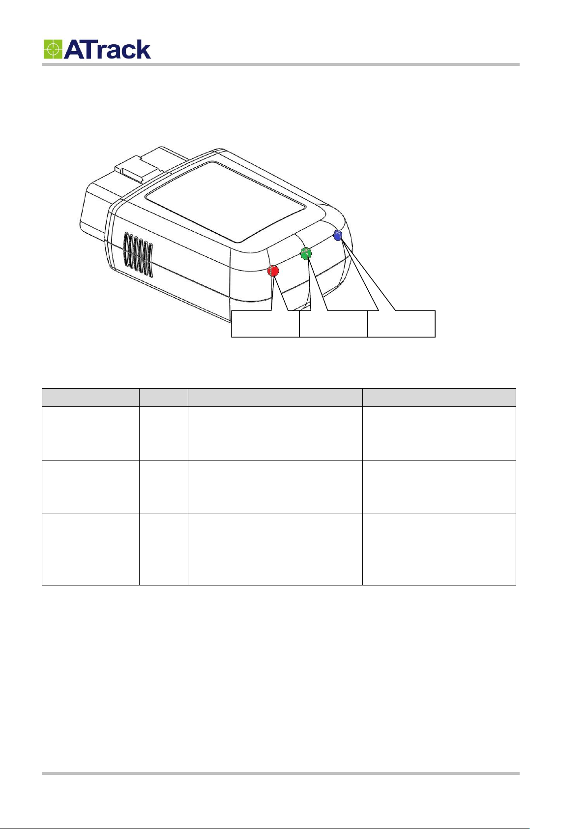
LED Indicators
Color
LED Status
Description
OBD
Green
Solid OFF
Fast blinking
Blinking every 10 seconds
OBD Protocol not found
OBD-II data transmission.
Deep sleep mode
GPS
Blue
Solid OFF
Blinking every 1 second
Solid ON
GPS power OFF
GPS not fix
GPS Location Fix
GSM
Red
Solid OFF
Blinking every 1 second
Blinking every 2 second
Blinking twice every 2 second
GSM Power OFF
GSM no signal
GSM registered
GPRS connected
GPS
GSM
OBD
Confidential Document
e following table describes the LED states:
© ATrack Technology Inc. All Rights Reserved. Page 9 of 27
Page 10
55.. CCoonnffiigguurraattiioonn
55..11.. CCoonnnneeccttiinngg aa DDeevviiccee UUssiinngg HHyyppeerrTTeerrmmiinnaall
Confidential Document
You can explore many of AX9’s great features through AT commands. The commands can be sent to AX9 via USB,
SMS or cellular network (e.g. GPRS/CDMA/UMTS).
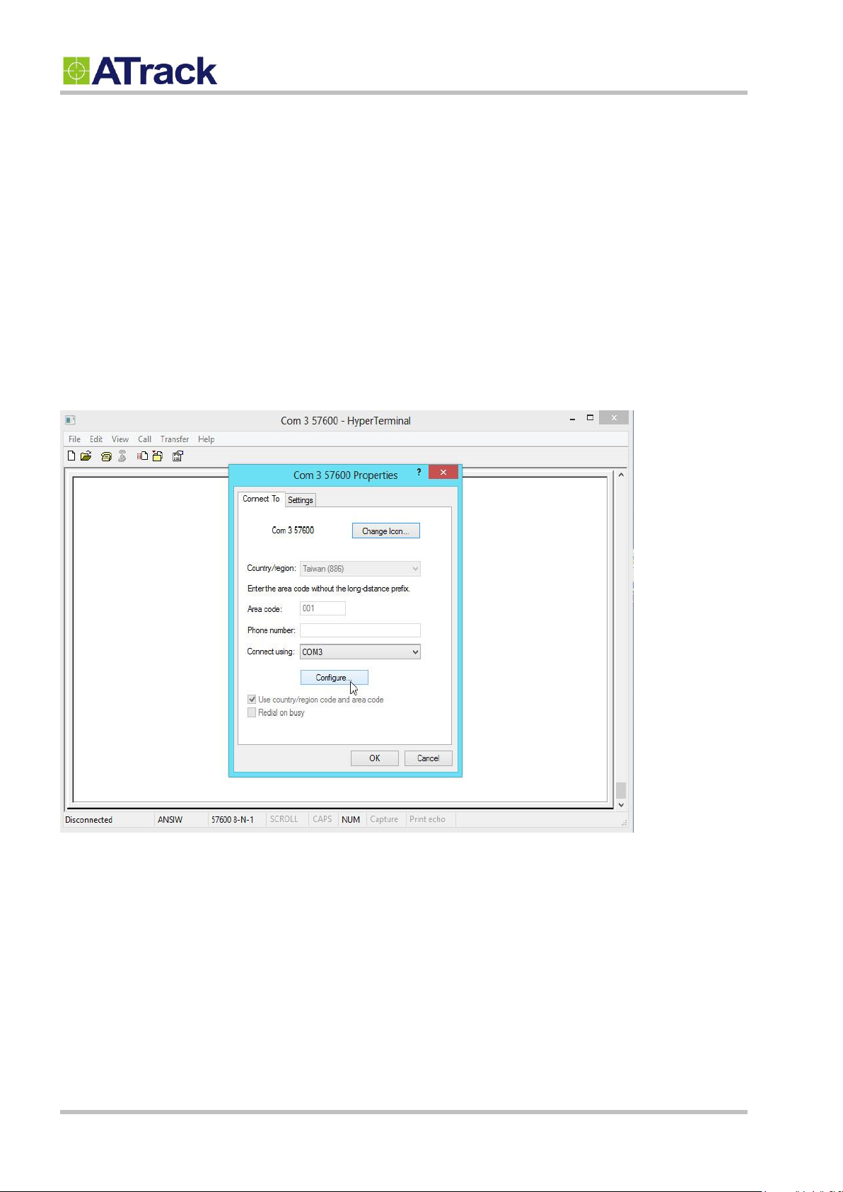
The following example shows how to connect the AX9 through Hyper Terminal. You may use other popular terminal
emulators such as Putty or Tera Term Pro to establish a console session with the AX9.
(1) Run HyperTerminal and select the correct COM port and click on the [Configure…] button.
© ATrack Technology Inc. All Rights Reserved. Page 10 of 27
Page 11
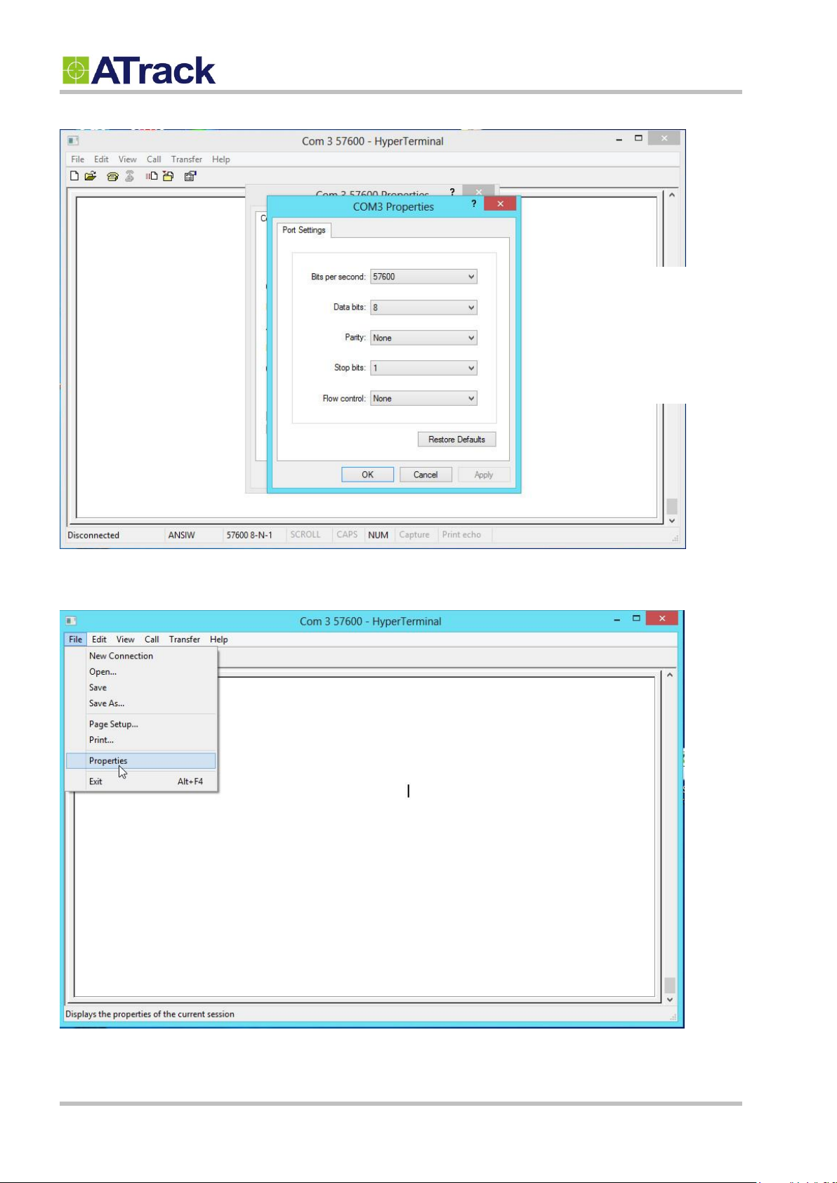
Bits per second: 57600
Data Bits: 8
Parity: None
Stop Bits: 1
Flow Control: None
Confidential Document
(2) Port Settings should be as follows. Click on the [OK] button to close the Properties window.
(3) Click on [File][Properties]
© ATrack Technology Inc. All Rights Reserved. Page 11 of 27
Page 12
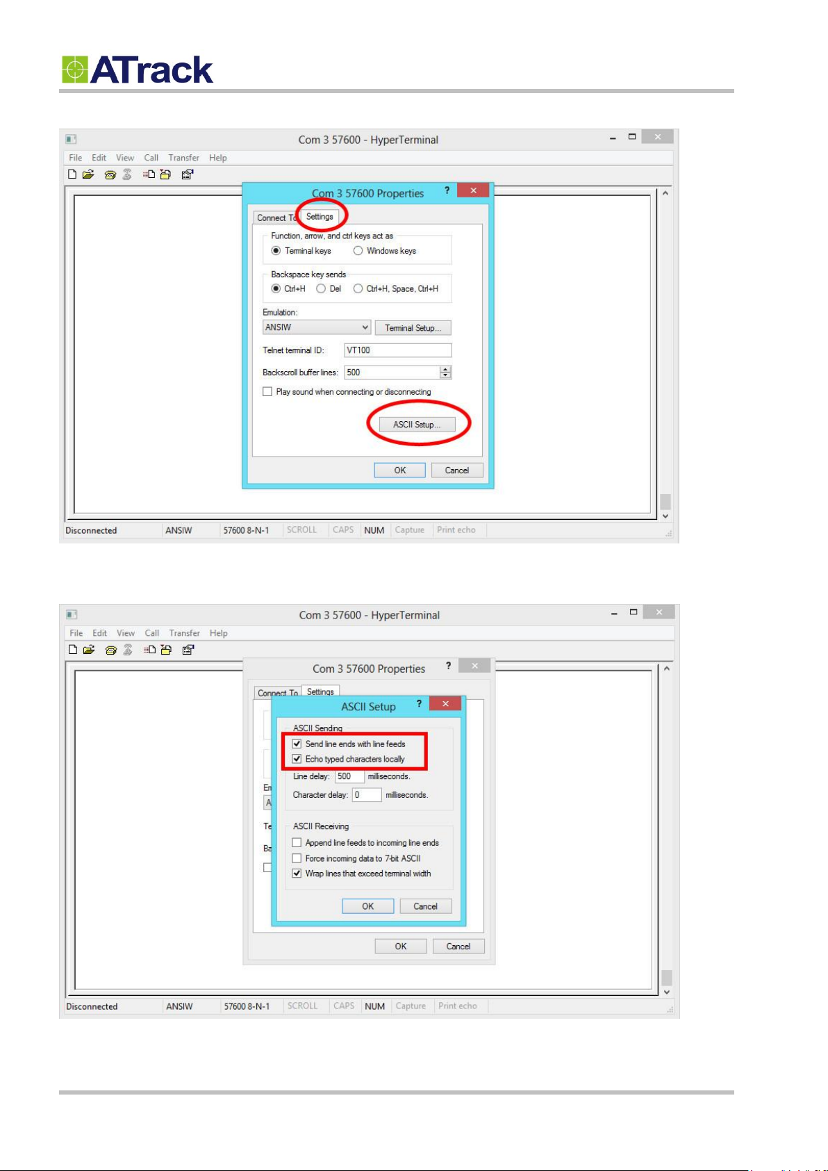
(4) Click on the [Settings] tab and click on the [ASCII Setup…] button.
Confidential Document
(5) Check the following options and click on the [OK] button.
© ATrack Technology Inc. All Rights Reserved. Page 12 of 27
Page 13
Confidential Document
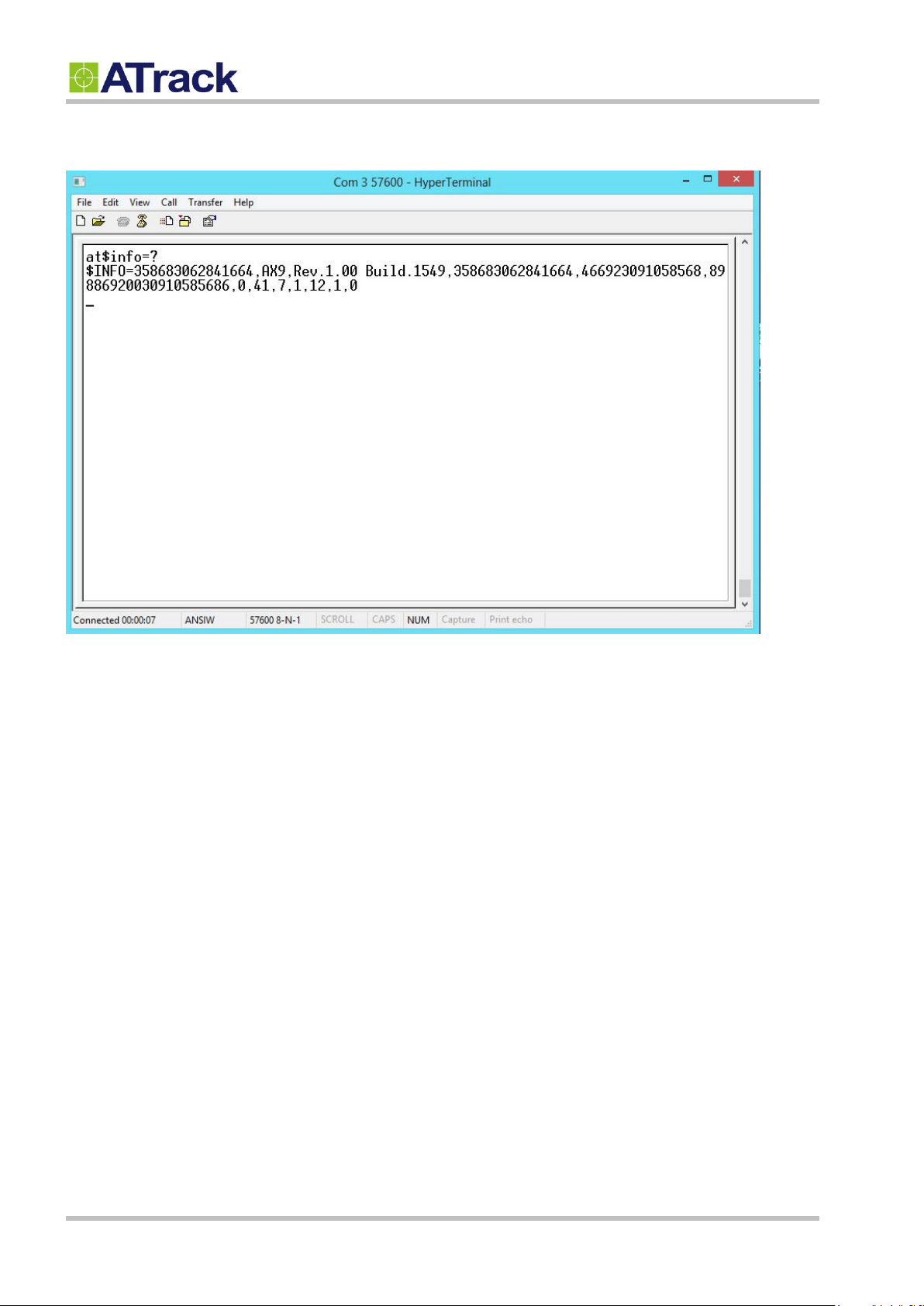
(6) Power up the device and you can now begin to send AT commands to query the device. Please refer to the
ATrack Protocol Document for details.
© ATrack Technology Inc. All Rights Reserved. Page 13 of 27
Page 14
55..22.. CCoonnnneeccttiinngg aa DDeevviiccee UUssiinngg AAXXTTooooll
Confidential Document
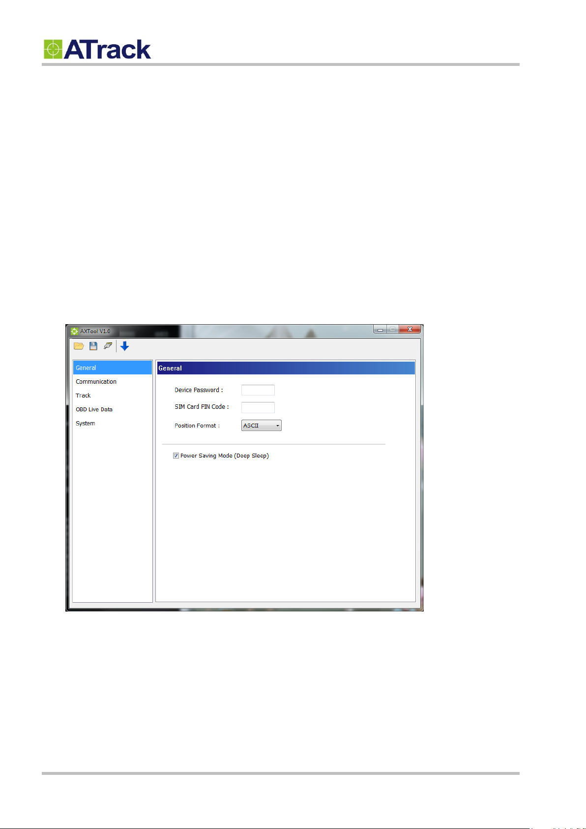
The AXTool is a simple configuration tool which is useful for users to configure the basic settings of the AX9. For
advanced configurations, please refer to the ATrack Protocol Document for details.
General Setting
[Device Password]: The device password is used for protecting device configurations. You can have the
maximum of 6 characters.
[SIM Card PIN Code]: Enter the PIN code of a SIM card if you a PIN code enabled.
[Position Format]: Select position format for all reports.
[Power Saving Mode]: Enable/Disable the power saving mode. When the power saving mode is enabled, the
AX9 device will go into deep sleep mode after 1 minute of engine off.
© ATrack Technology Inc. All Rights Reserved. Page 14 of 27
Page 15
Confidential Document
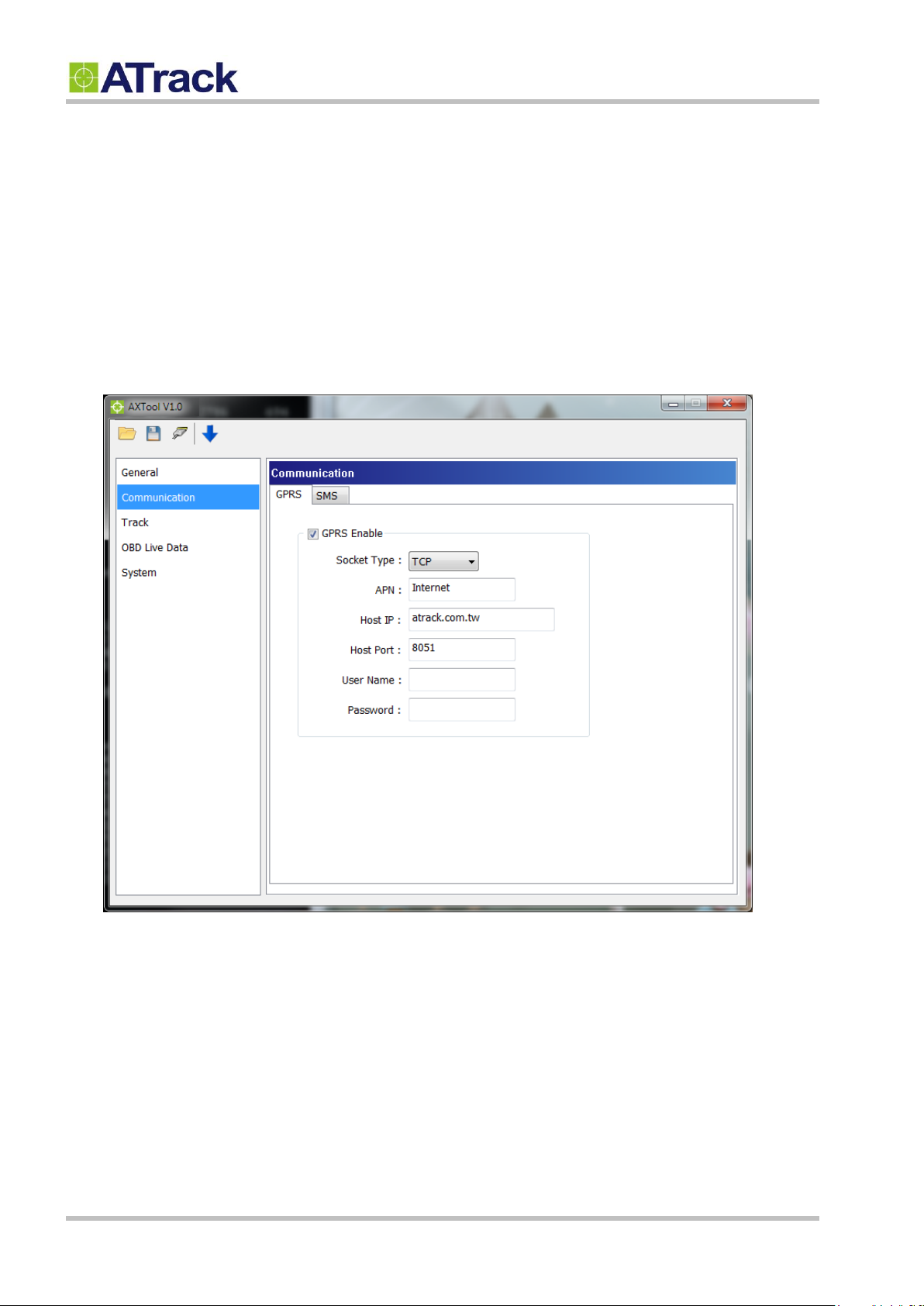
Communication Setting
[GPRS Enable]: Enable GPRS communication
[Socket Type]: Select TCP or UDP for GPRS communication
[APN]: Access Point Name for GPRS connection. (Please contact your cellular network carrier for the
information)
[Host IP]: Enter the IP address or domain name of host server
[Host Port]: Enter Port number of the remote host server
[User Name]: The GPRS user name. (Please contact your cellular network carrier for the information)
[Password]: The GPRS password. (Please contact your cellular network carrier for the information)
© ATrack Technology Inc. All Rights Reserved. Page 15 of 27
Page 16
Confidential Document
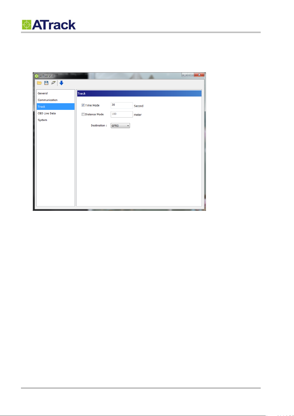
Track Setting
You may configure a tracking interval when the vehicle engine is ON. When [Time Mode] and [Distance Mode]
are both selected, the tracking behavior will operate in AND condition.
© ATrack Technology Inc. All Rights Reserved. Page 16 of 27
Page 17
Confidential Document
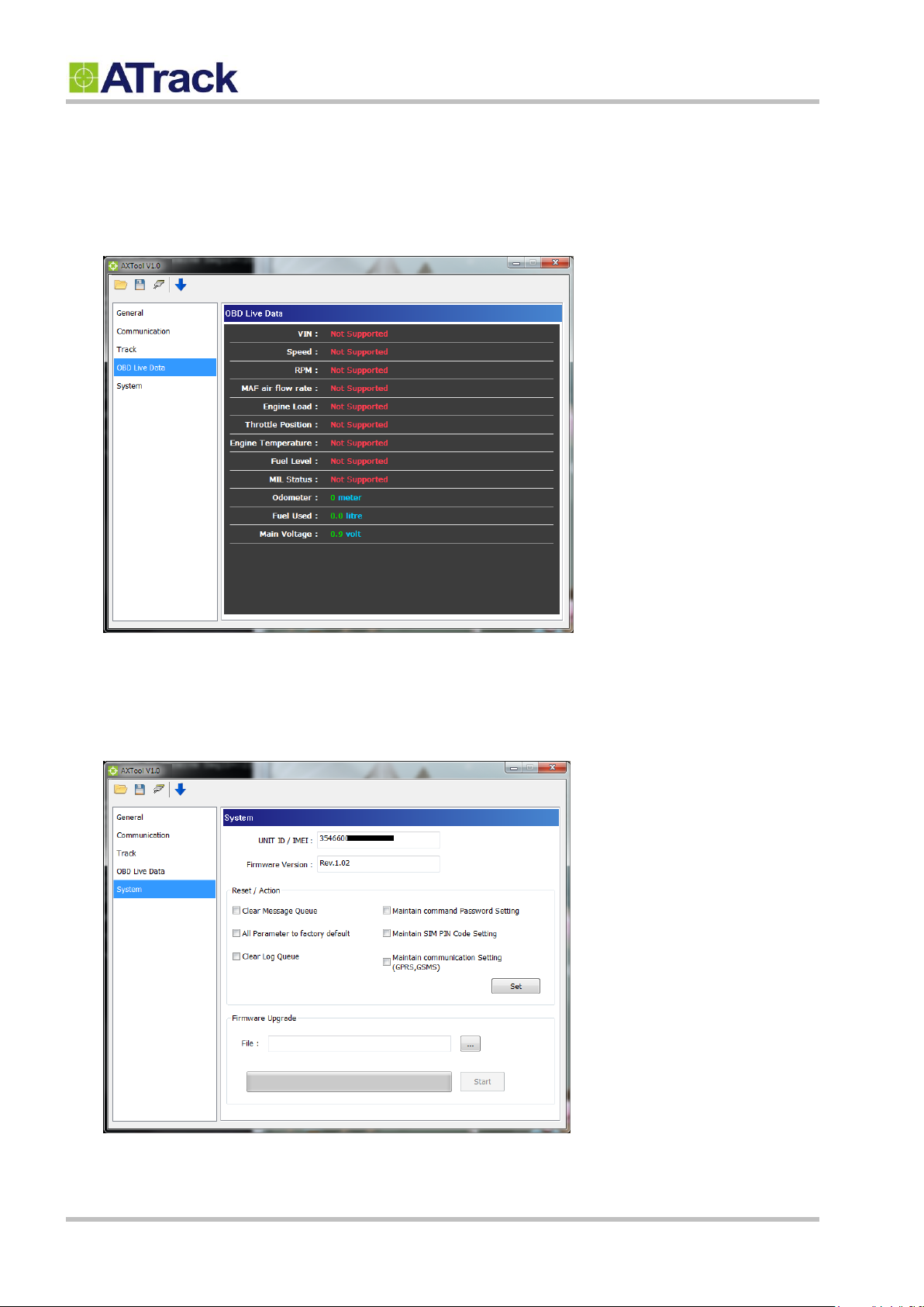
OBD Live Data
When the AX9 is connected to a vehicle’s OBD-II port, you will see the OBD live data such as VIN, Speed,
RPM, MAF air flow rate, Engine Load, Throttle Position, Engine Temperature, Fuel Level, MIL Status,
Odometer, Fuel Used, and Main Voltage.
System Setting
The [System] setting will show the current connected device information. The [Reset/Action] function can be
used to reset parameters or clear buffered messages of the device.
© ATrack Technology Inc. All Rights Reserved. Page 17 of 27
Page 18
Confidential Document
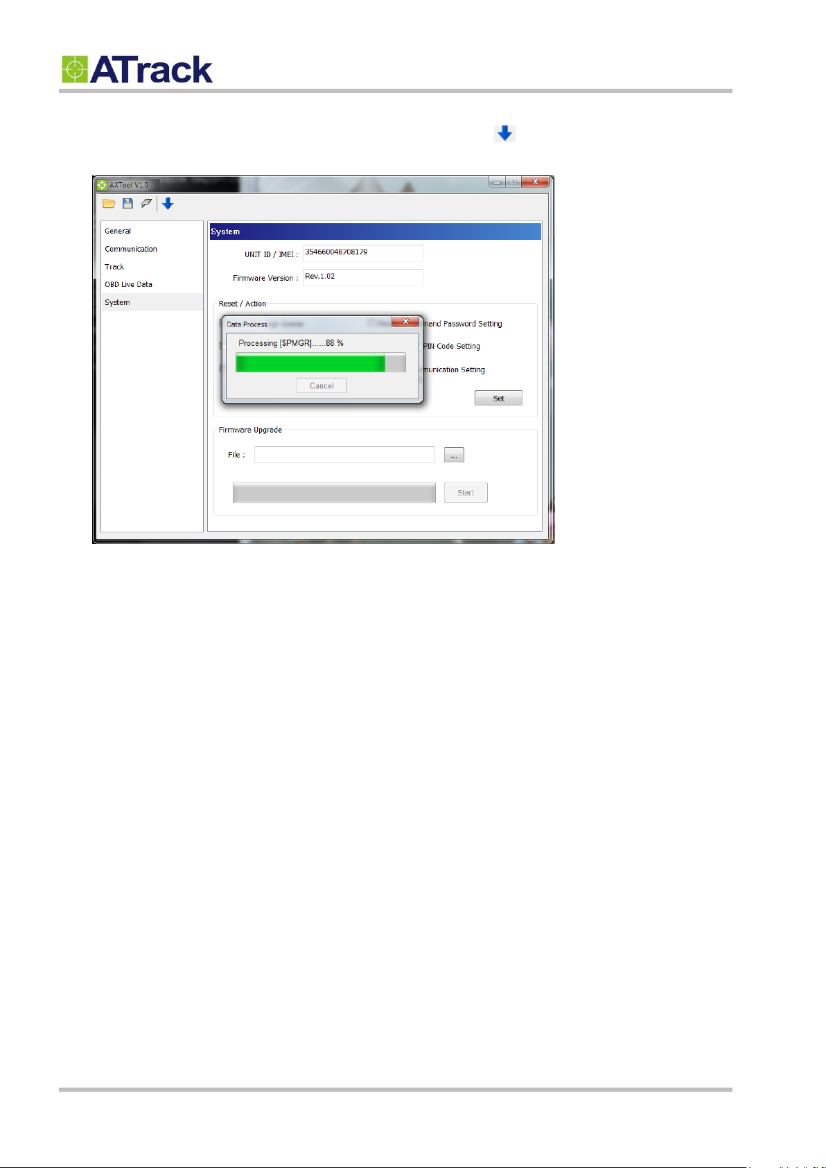
Uploading Setting To Device
Once all the settings are entered, use the Blue Downward Arrow ( ) to upload the settings to the device. A
popup window will show the progress. When it finishes, the popup window will close.
© ATrack Technology Inc. All Rights Reserved. Page 18 of 27
Page 19
55..33.. FFiirrmmwwaarree UUppggrraaddee
Confidential Document
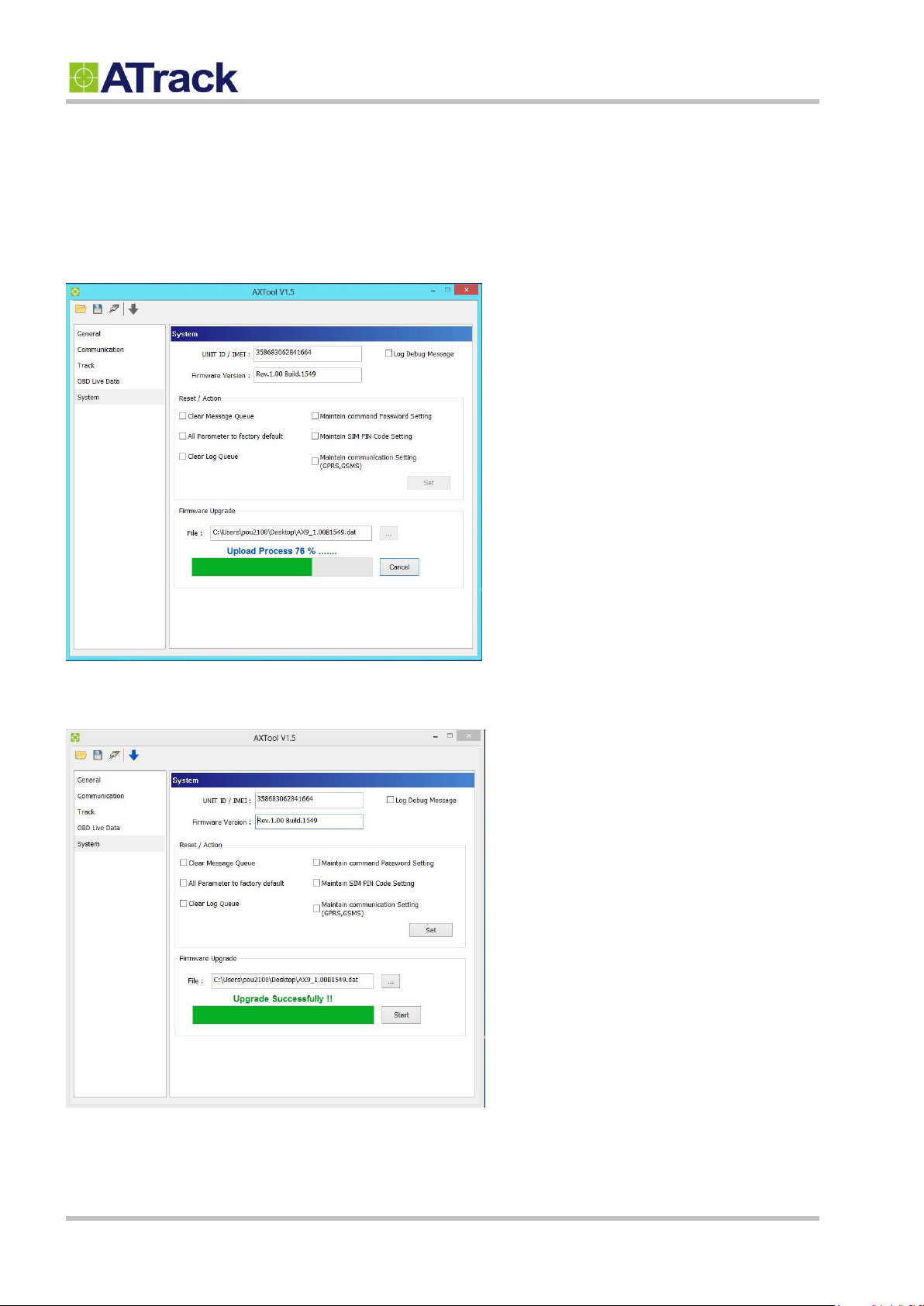
Open the AXTool program and click on [System] on the menu.
Browse the firmware file which is provided by ATrack and click on the [Start] button.
When you see “Upgrade Successfully!!”, that means the device firmware is upgraded.
© ATrack Technology Inc. All Rights Reserved. Page 19 of 27
Page 20
66.. BBlluueettooootthh AApppplliiccaattiioonnss
66..11.. UUssiinngg aann AAnnddrrooiidd MMoobbiillee ttoo CCoonnnneecctt ttoo yyoouurr AAXX99
Confidential Document
In this section, we will walk you through on how to set up a Bluetooth connection between your AX9 and your
Android mobile/PC.
For this demonstration purpose, we will use the "Bluetooth SPP Pro" app, which can be downloaded from this
website address: https://play.google.com/store/apps/details?id=mobi.dzs.android.BLE_SPP_PRO&hl=en
A 2-D barcode for your phone to scan and download from market:
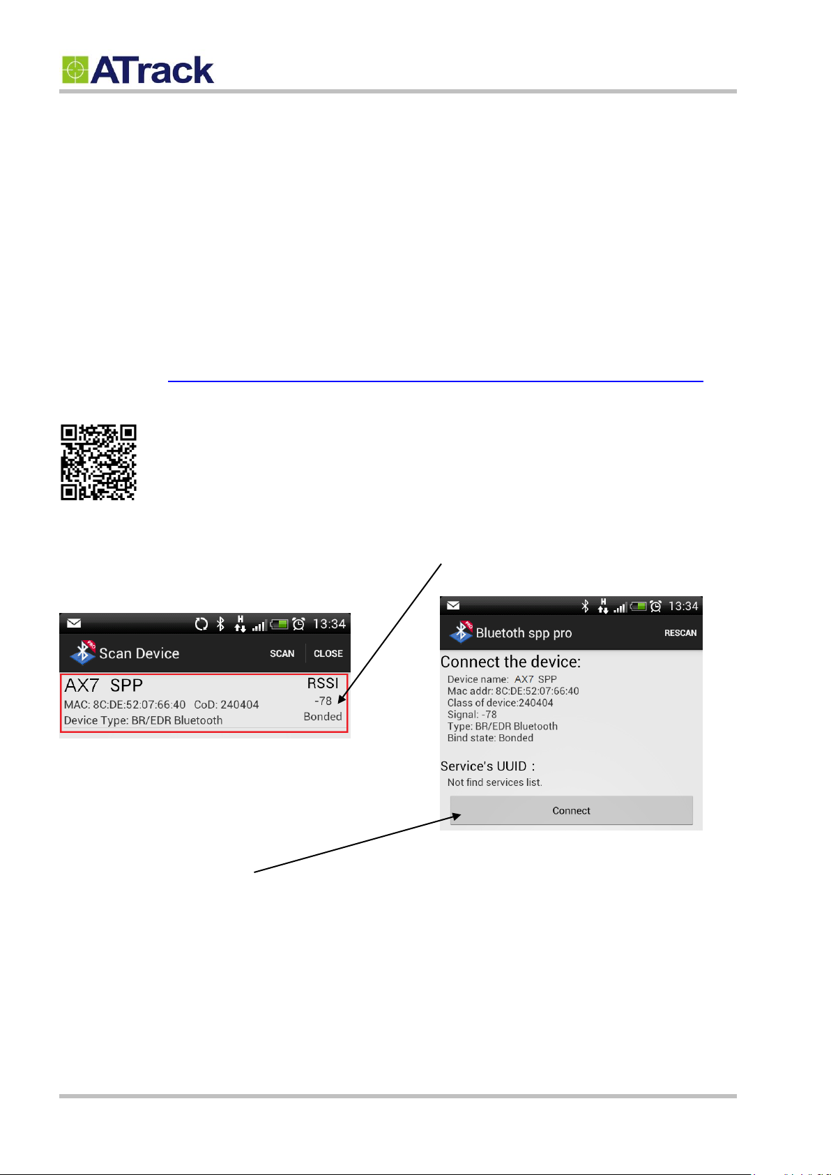
After the installation, launch the app which scans for
available Bluetooth devices. The AX9 device is listed
on the list as shown below:
Tap on the Connect button.
Tap on the area marked in red, then the device details
are shown as below:
© ATrack Technology Inc. All Rights Reserved. Page 20 of 27
Page 21
66..22..
UUssiinngg aa PPCC ttoo ccoonnnneecctt ttoo yyoouurr AAXX99
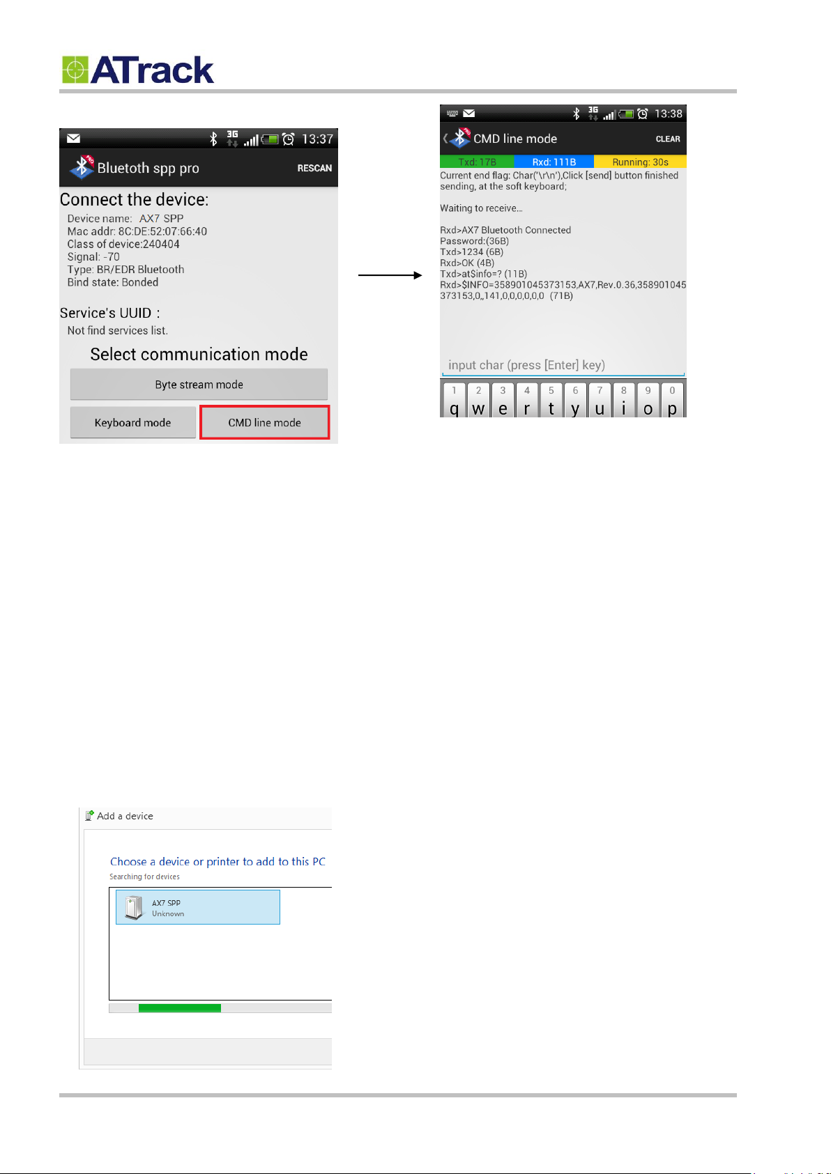
Tap on CMD line mode.
Confidential Document
The command prompt shows up:
After a successful connection, you can see a response message showing "Rxd>AX9 Bluetooth Connected".
By default, there is no password. Therefore, the AT$BTEN command may be used to setup a password for a
Bluetooth authentication. If a password is set, then a password prompt would be shown and you would need
to type your password in order to communicate with the device.
In this example, Windows 8 is used for this demonstration. The same principle can also be applied when
installing a device on a Windows 7 platform. At first, you need to have Hyper-Terminal installed. Next, power
up the AX9 device, and then on your PC, go to Control Panel -> Devices and Printers -> right click on a
blank space and select Add devices and printers. Double click on AX9 SPP to install the device.
© ATrack Technology Inc. All Rights Reserved. Page 21 of 27
Page 22
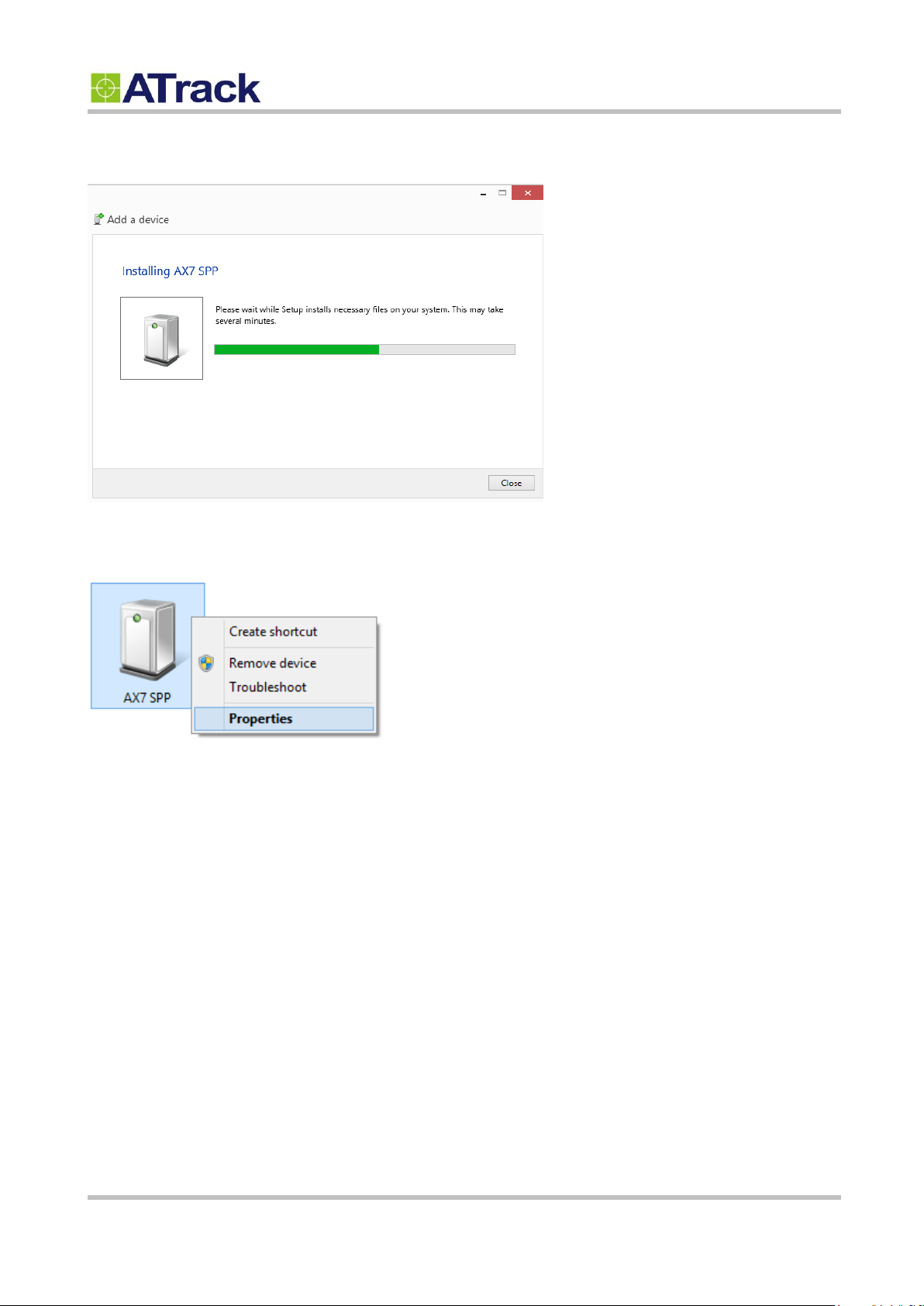
The device is being installed as shown below.
Confidential Document
Under Devices and Printers, please right-click on AX9 SPP and select Properties.
© ATrack Technology Inc. All Rights Reserved. Page 22 of 27
Page 23
Confidential Document
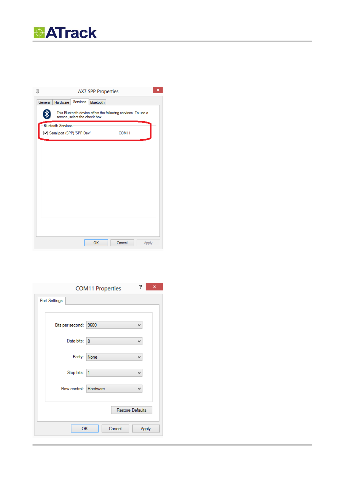
Select Services in order to check which COM port the device is connected to. In this example, the device is
connected via COM11.
Launch the Hyper-Terminal and select COM11. Please select the following settings during the connection
setup.
© ATrack Technology Inc. All Rights Reserved. Page 23 of 27
Page 24
66..33..
BBlluueettooootthh CCoommmmaannddss
Confidential Document
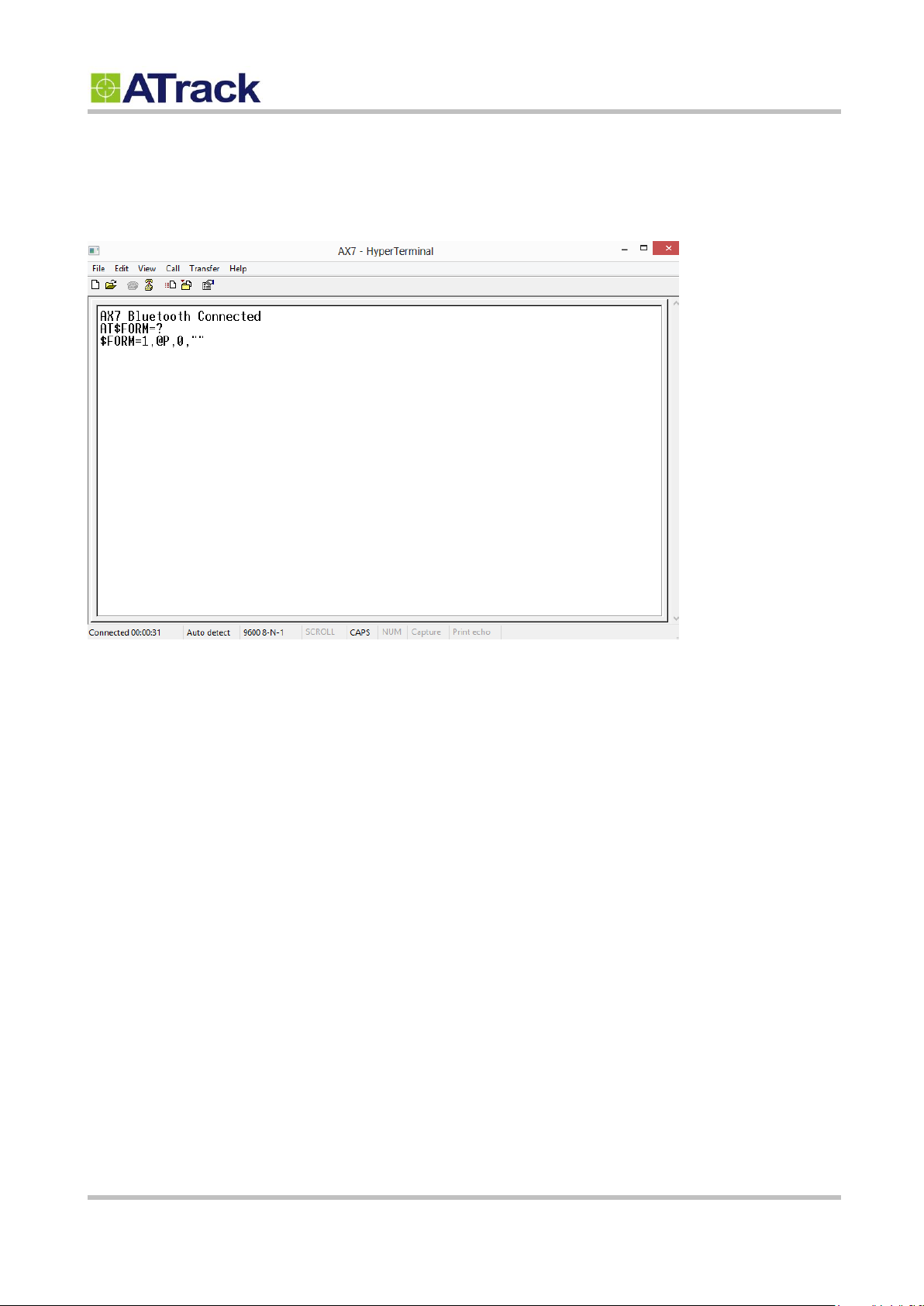
Once it is connected, there is a response message showing "AX9 Bluetooth Connected". You can issue
some AT commands later on.
AT$BTEN=<Mode>, <Password>
<Mode>: 0 - SPP Profile (Default)
<Password>: 4 characters password for connection authorization.
Example: Set "1234" for the Bluetooth connection password
AT$BTEN=0,"1234"
After connecting to the AX9, you will need to input the password with the ending characters
<CR><LF> and send the password to the AX9 in order to establish the connection. This password
sending has to be done within 1 minute after a successful pairing. A failure will result in
disconnection and cause the pairing process to repeat again.
© ATrack Technology Inc. All Rights Reserved. Page 24 of 27
Page 25

77.. AAppppeennddiixx
77..11..
FFCCCC RReegguullaattiioonnss
Confidential Document
This device complies with part 15 of the FCC Rules. Operation is subject to the following two conditions:
(1) This device may not cause harmful interference, and (2) this device must accept any interference
received, including interference that may cause undesired operation.
This device has been tested and found to comply with the limits for a Class B digital device, pursuant to
Part 15 of the FCC Rules. These limits are designed to provide reasonable protection against harmful
interference in a residential installation. This equipment generates, uses and can radiated radio
frequency energy and, if not installed and used in accordance with the instructions, may cause harmful
interference to radio communications. However, there is no guarantee that interference will not occur in
a particular installation If this equipment does cause harmful interference to radio or television reception,
which can be determined by turning the equipment off and on, the user is encouraged to try to correct
the interference by one or more of the following measures:
Reorient or relocate the receiving antenna.
-Increase the separation between the equipment and receiver.
-Connect the equipment into an outlet on a circuit different from that to which the receiver is connected.
-Consult the dealer or an experienced radio/TV technician for help.
Changes or modifications not expressly approved by the party responsible for compliance could void the
user‘s authority to operate the equipment.
Radiation Exposure Statement:
This equipment complies with FCC radiation exposure limits set forth for an uncontrolled environment.
This equipment should be installed and operated with minimum distance 20cm between the radiator &
your body. This equipment must not be co-located or operated in conjunction with any other antenna or
radio transmitter.
© ATrack Technology Inc. All Rights Reserved. Page 25 of 27
Page 26
77..22..
HHaarrddwwaarree SSppeecciiffiiccaattiioonn
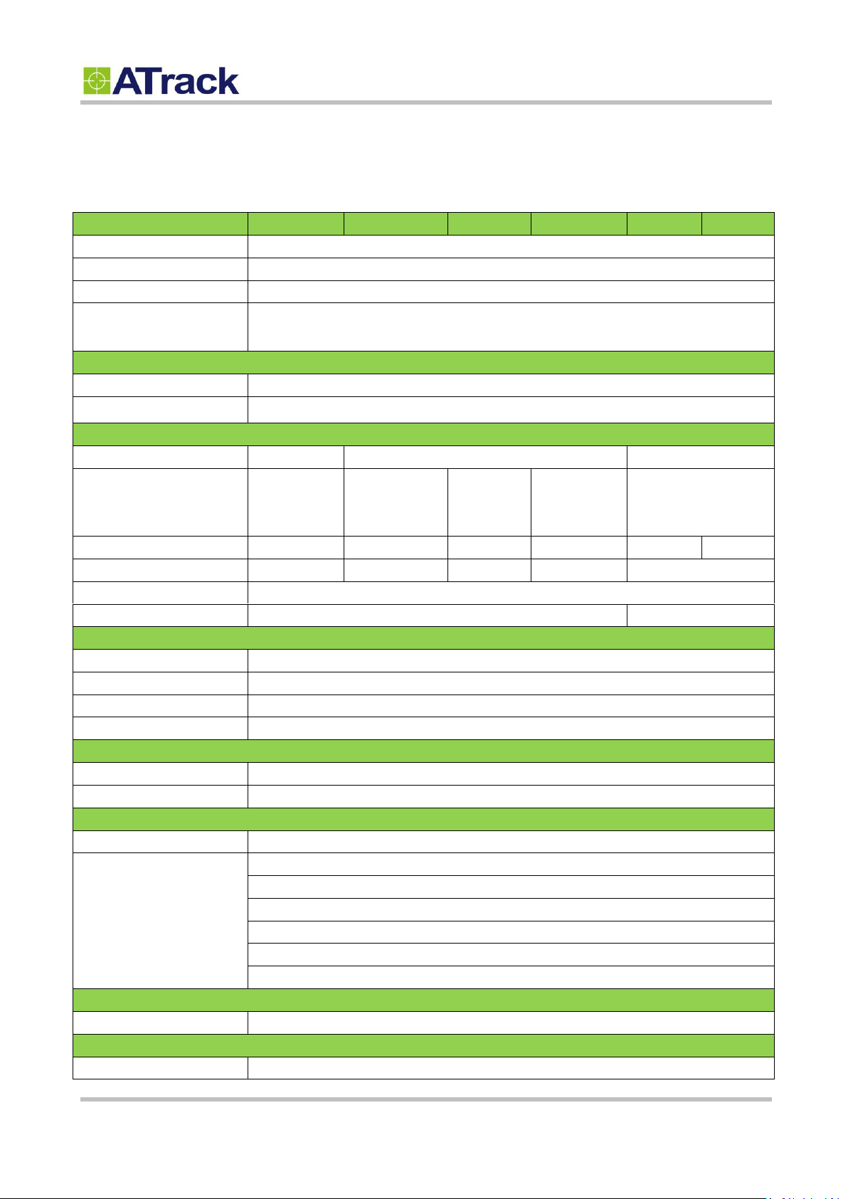
Model Number
AX9(GG)
AX9(UA)
AX9(UE)
AX9(UG)
AX9(CV)
AX9(CS)
Dimensions (L x W x H)
63 x 54 x 28 mm
Weight
73 g
Housing
Flame Retardant PC(UL 94 V-0)
Operating
Temperature
-40°C ~ 85°C (-40°F ~ 185°F)
Electrical Characteristics
Power Supply
8V ~ 36V DC
Current Consumption
Operating : Max.140mA@12V, Deep Sleep Mode 1.9 mA@12V
Cellular Network Communication
Technology
GPRS
WCDMA/HSPA
CDMA2000 1xRTT
Frequency(MHz)
850/900
1800/1900
850/1900
900/2100
800/850
900/1700
1900/2100
800/1900
Carrier Support
Worldwide
USA/Canada
EU/APAC
Worldwide
Verizon
Sprint
GSM/GPRS
Quad-band
850/1900
900/1800
Quad-band
N/A
Cellular Antenna
Internal Cellular antenna
SIM Card
1.8V/3V Mini SIM(2FF)
N/A
GPS/GLONASS
Receiver
56 Channels, --161dBM(GPS)/-158dBm(GLONASS) Tracking sensitivity
Accuracy
2.5 m CEP / 4.0 m CEP
GPS Antenna
Internal GPS active antenna
GPS Data Buffer
8 MB
Accelerometer
3-Axis
Z,X,Y
Resolution
±16g, 400Hz
OBD-II Communication
Connector Type
SAE J1962 Male Connector (Type B)
Protocol Supported
ISO 15765-4 (CAN), 11/29Bit ID, 250/500Kbaud
ISO 14230-4 (KWP2000)
ISO 9141-2 (Asian, European, Chrysler vehicles)
SAE J1850 VPW (GM vehicles)
SAE J1850 PWM (Ford vehicles)
FMS / SAE J1939(Heavy-duty trucks)
Device I/O Port
Mini USB
1 (For I/O extension port)/ For device configuration
Standard Accessories
USB cable
Length 1.2 m
Confidential Document
© ATrack Technology Inc. All Rights Reserved. Page 26 of 27
Page 27
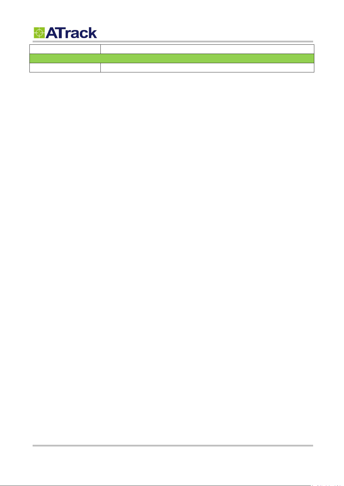
Backup Battery
Internal 3.7V 90mAh Rechargeable Lithium-ionBattery
Optional Accessories
Bluetooth Module
Bluetooth 3.0 EDR+ BLE 4.0 dual mode
Confidential Document
© ATrack Technology Inc. All Rights Reserved. Page 27 of 27
 Loading...