

Page 1

AU7
User Manual
Revision:
04
Revision Date:
2016/03/28
ATrack Technology Inc.
4F., No. 12, Wunhu St.,Neihu Dist.,
Taipei City 11445, Taiwan (R.O.C.)
Tel: +886-2-27975852
Fax: +886-2-27974030
http://www.atrack.com.tw
Page 2

Confidential Document
© ATrack Technology Inc. All Rights Reserved. Page 2 of 15
Tale of Contents
1. Notification .............................................................................................................................. 3
1.1. Disclaimer .................................................................................................................................... 3
1.2. Copyright ...................................................................................................................................... 3
1.3. Warning ........................................................................................................................................ 3
2. Hardware ................................................................................................................................. 4
2.1. Package Content ......................................................................................................................... 4
2.2. Pin Assignments........................................................................................................................... 5
2.2.1. Serial Cable (JST Female Connector to DB9 Female Connector) .......................................... 5
2.2.2. Device I/O Ports ....................................................................................................................... 5
2.3. LED Indications ............................................................................................................................ 7
2.4. Device Installation ........................................................................................................................ 8
3. Firmware Upgrade ................................................................................................................. 9
3.1. Firmware Upgrade via RS232...................................................................................................... 9
4. AT$IOCG Command Reference.......................................................................................... 13
5. Appendix ................................................................................................................................ 14
5.1. Hardware Specification .............................................................................................................. 14
5.2. FCC Regulations ........................................................................................................................ 15
Page 3

Confidential Document
© ATrack Technology Inc. All Rights Reserved. Page 3 of 15
11.. NNoottiiffiiccaattiioonn
11..11.. DDiissccllaaiimmeerr
This document, and all other related products, such as device, firmware, and software, is developed by
ATrack Technology Inc. thoroughly. At the time of release, it is most compatible with specified firmware version.
Due to the functionalities of the devices are being developed and improved from time to time, the change in
the protocol, specification, and firmware functions are subjects to change without notice. ATrack Technology
Inc. is obligated to modify all the documentation without the limitation of time frame. A change notice shall be
released to ATrack Technology Inc. customers upon the completion of document modification.
ATrack Technology Inc. products are not intended to be used as life support or rescue equipments. ATrack
Technology Inc. is not liable for any loss or injury caused by using or referencing to any products. Any possible
means of using or integrating ATrack Technology Inc. products shall be avoided.
11..22.. CCooppyyrriigghhtt
ATrack Technology Inc. holds all parts of intellectual rights applicable in the copyright laws in all the countries.
Any or all parts of this document shall not be exposed to non-authorized party without any form of approval
from ATrack Technology Inc. Any forms, including but not limited to oral, copy, or internet sharing, of releasing
or exposing information to an unauthorized party shall be prohibited. ATrack Technology Inc. reserves the
rights of litigation in the violation of such copyright laws.
11..33.. WWaarrnniinngg
Connecting the wire inputs can be hazardous to both the installer and your vehicle’s electrical system if not
done by an experienced installer. This document assumes you are aware of the inherent dangers of working
in and around a vehicle and have a working understanding of electricity.
Page 4
Confidential Document
© ATrack Technology Inc. All Rights Reserved. Page 4 of 15
22.. HHaarrddwwaarree
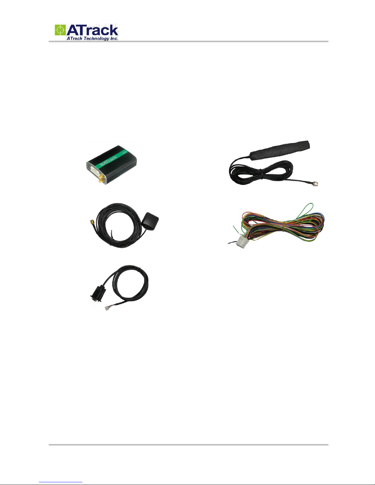
22..11.. PPaacckkaaggee CCoonntteenntt
Each package contains the following device/accessories:
Device * 1
GPS Antenna * 1
Serial Cable * 1
GSM/UMTS Antenna * 1
Power/IO Cable * 1
Page 5
Confidential Document
© ATrack Technology Inc. All Rights Reserved. Page 5 of 15
22..22.. PPiinn AAssssiiggnnmmeennttss
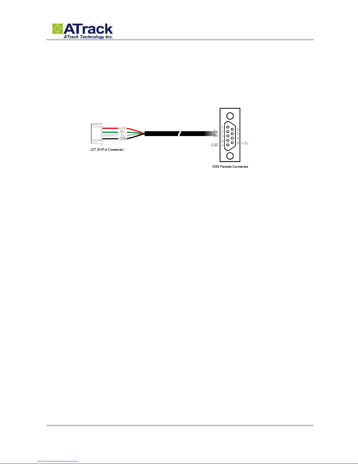
22..22..11.. SSeerriiaall CCaabbllee ((JJSSTT FFeemmaallee CCoonnnneeccttoorr ttoo DDBB99 FFeemmaallee CCoonnnneeccttoorr))
The Pin 9 is a power output port to provide a 5V, 300mA power source for accessory that connects to the
serial port. If the connected accessory requires more power, please use external power source instead.
22..22..22.. DDeevviiccee II//OO PPoorrttss
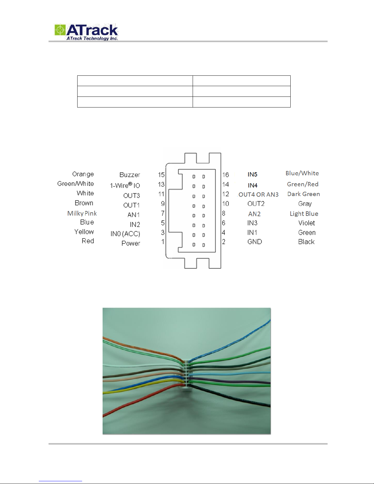
To support a wide range of hardware applications, the AU7 is equipped with a large number of inputs and
outputs.
6 Digital Inputs (IN0, IN1, IN2, IN3, IN4 and IN5): IN0, IN1 and IN4 are positive triggers (Triggering
Voltage Range: 3.7 ~ 40V). IN0 is dedicated to ACC (Ignition). IN2, IN3, and IN5 are negative triggers
(Triggering Voltage Range 0 ~ 0.8V). These triggers can be used in the following application areas:
engine detection, car door open/close detection, and Panic Button in case of any emergency.
3 Digital Outputs (OUT1, OUT2, and OUT3): They are normally used for engine or ignition
immobilization. Please refer to our AU7 Quick Start Guide for details on how to set up relays for these
applications. These digital outputs are open collector type. When in the “ON” state, these outputs are
grounded (GND). When in the “OFF” state, it forms an open circuit. Note: Please do not connect a
positive voltage any output pin!!!
2 Analog Inputs (AN1 and AN2): Each input is usually connected to an external temperature sensor or
fuel level senor. The voltage range of AN1 is 0 ~ 40V 12-bits resolution. The voltage range of AN2 is 0 ~
5V 12-bits resolution.
1 Digital Output/Analog Input (OUT4/AN3): This port may be configured as a digital output or analog
input through the AT$IOCG command. The voltage range of AN3 is 0 ~ 40V 12-bits resolution. Refer to
the AT$IOCG command reference section for details. Note: Please do not connect a positive voltage
to an output pin!!!
1-Wire
: it uses a single wire to transmit both data and power. You may use 1-Wire
to connect up to
five devices, for instance, one iButton and four temperature sensors.
Page 6
Confidential Document
© ATrack Technology Inc. All Rights Reserved. Page 6 of 15
Family Code
Model
01h
DS1990A (iButton)
28h
DS18B20 (Temperature Sensor)
16-pin male on-board Power I/O Connector
16-pin female Power I/O Cable
Compatible Devices Supported by 1-Wire Application
Page 7
Confidential Document
© ATrack Technology Inc. All Rights Reserved. Page 7 of 15
22..33.. LLEEDD IInnddiiccaattiioonnss
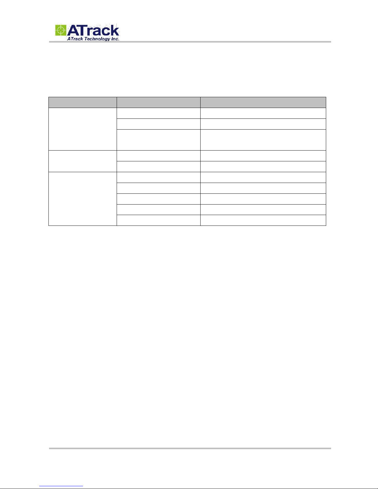
The following table describes LED states:
LED
Indication
Description
PWR (Green)
Solid On
In full operation mode
1 blink (0.1 sec.) in every 10 sec.
In sleep mode
1 sec. On, 1 sec. Off
GPS module off, External power lost, running on
backup battery
GPS (Red)
0.7 sec. On, 0.7 sec. Off
Searching for GPS signal
Solid On
Position get fixed
GSM (Red)
Off
GSM module off
0.7 sec. On, 0.7 sec. Off
Searching for GSM signal
0.2 sec. On, 2 sec. Off
Registered to GSM network
2 blinks in every 2 sec.
Connected to GPRS network
Continuous blinking
SIM PIN Error
Note: In the case of SIM PIN Error, the device will check the AT$SPIN every 10 minutes and try to
access the SIM again. The PIN will be validated 3 times and if it fails the last attempt, including the first
inserting time, the SIM card will be locked. Once the SIM is locked, you need to contact your GSM
carrier for the PUK in order to unlock the SIM card using your cell phone.
Page 8
Confidential Document
© ATrack Technology Inc. All Rights Reserved. Page 8 of 15
22..44.. DDeevviiccee IInnssttaallllaattiioonn
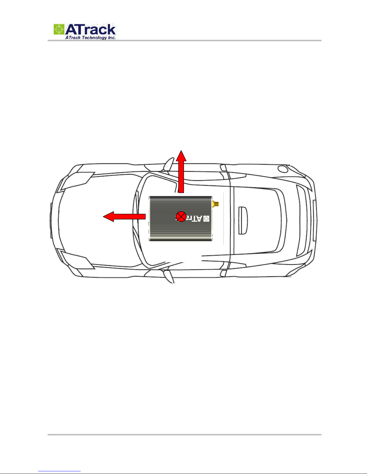
When installing the AU7 onto a vehicle, please make sure that the XYZ-position of the device follows the
exact same directions as shown below. The G-Sensor operates in such a way in order to detect harsh driving
events. The forces in each axis are used to determine the status of harsh driving events. If the following
installation is not practicable, it is advised to use the GPS for detecting harsh driving as an alternative.
1. Note: When installing the device, the vehicle should be parked on a horizontal place (not tilted).
Then, the device should be installed parallel to the vehicle body and fixed with a mounting
bracket or double-sided adhesive to ensure that the G-Sensor works properly.
2. Note: It is strongly recommended that an automobile technician is required to be involved for the
above installation.
Y-Axis
X-Axis
Z-Axis
Page 9
Confidential Document
© ATrack Technology Inc. All Rights Reserved. Page 9 of 15
33.. FFiirrmmwwaarree UUppggrraaddee
In this section, we are going to demonstrate how to do firmware upgrade on the AU7 via the serial connection.
Before doing the upgrade, connect the serial cable between the JST XHP-4 output connector and the serial
communication port (e.g. COM1 or COM2) on your PC. You may use a USB to serial port converter in case
your PC doesn’t have any COM port.
33..11.. FFiirrmmwwaarree UUppggrraaddee vviiaa RRSS223322
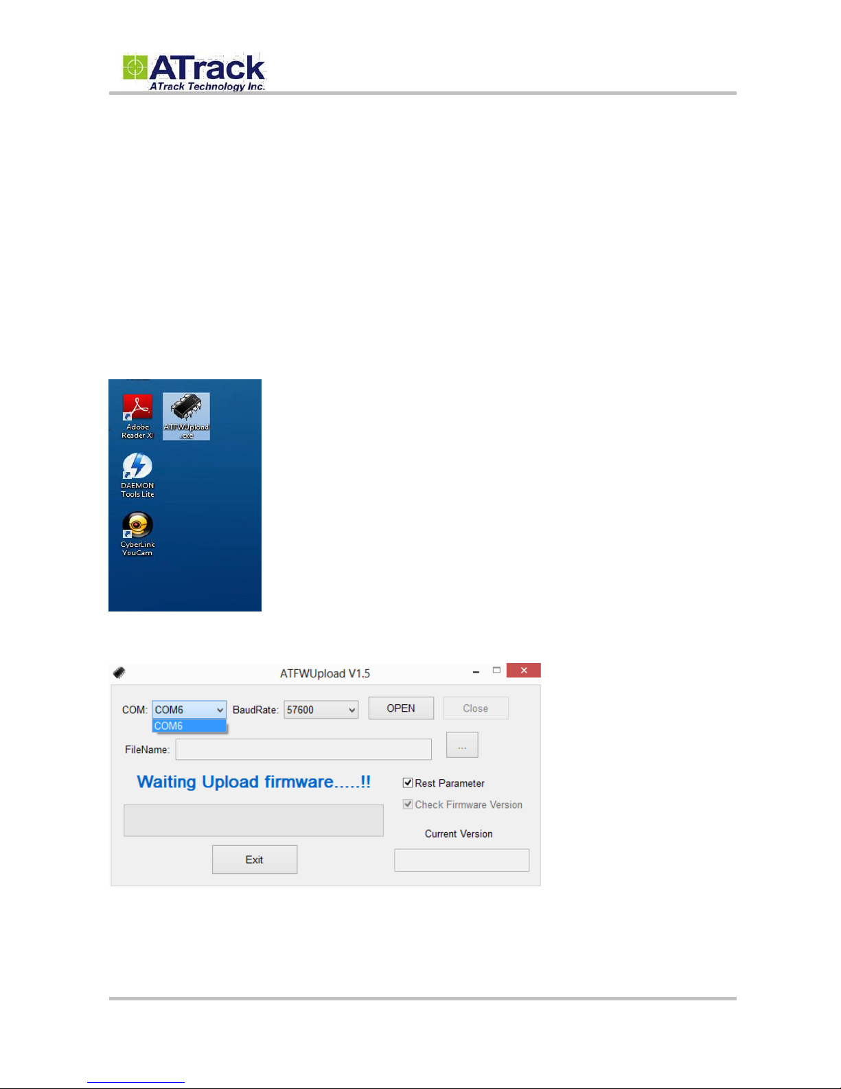
(1) Run the ATFWUpload program by double-clicking on it.
(2) Select the correct COM port.
Page 10
Confidential Document
© ATrack Technology Inc. All Rights Reserved. Page 10 of 15
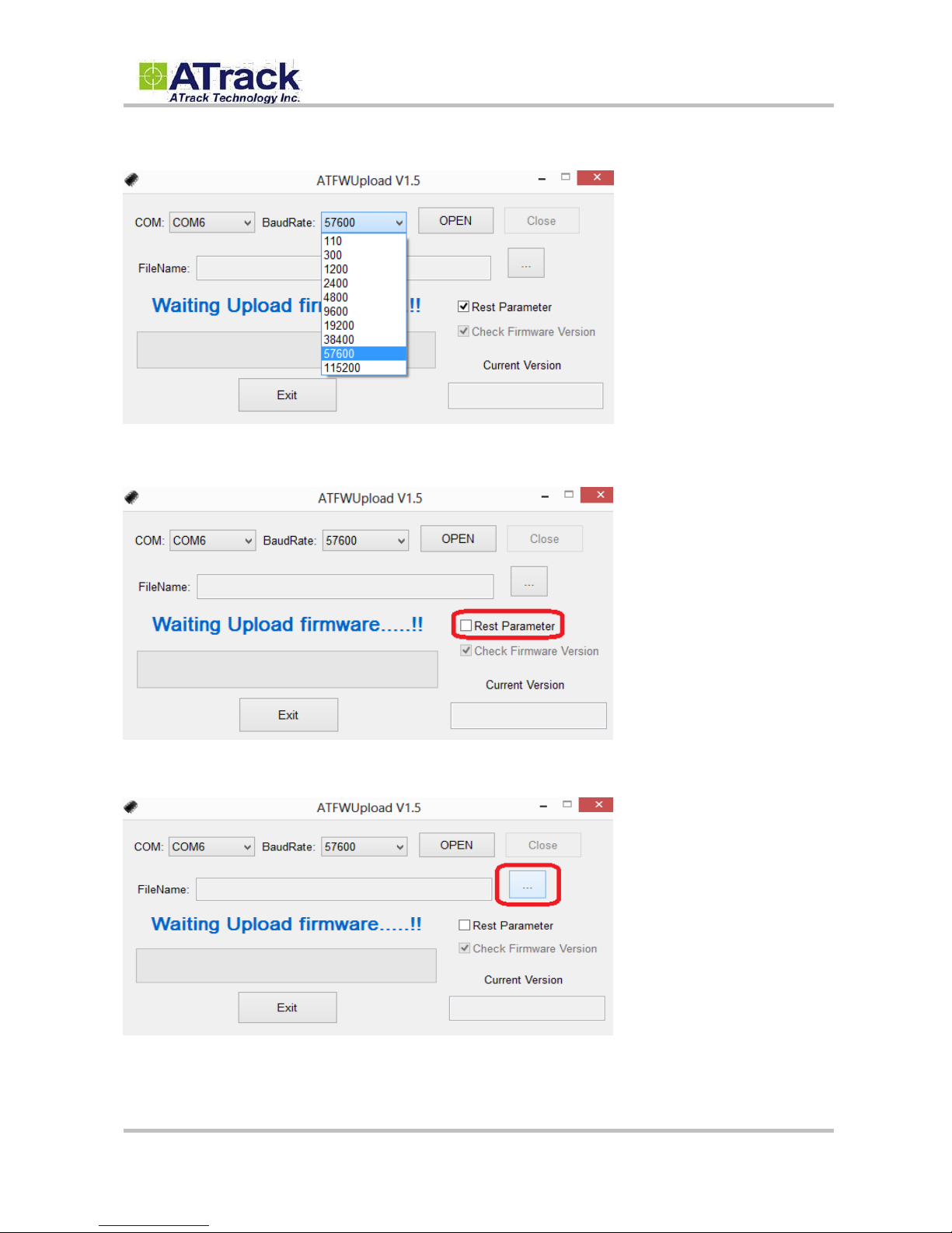
(3) Set the console baud rate to 57600.
(4) Un-tick the check box next to Rest Parameter.
(5) Click on the […] button to browse the firmware file where you saved.
Page 11
Confidential Document
© ATrack Technology Inc. All Rights Reserved. Page 11 of 15
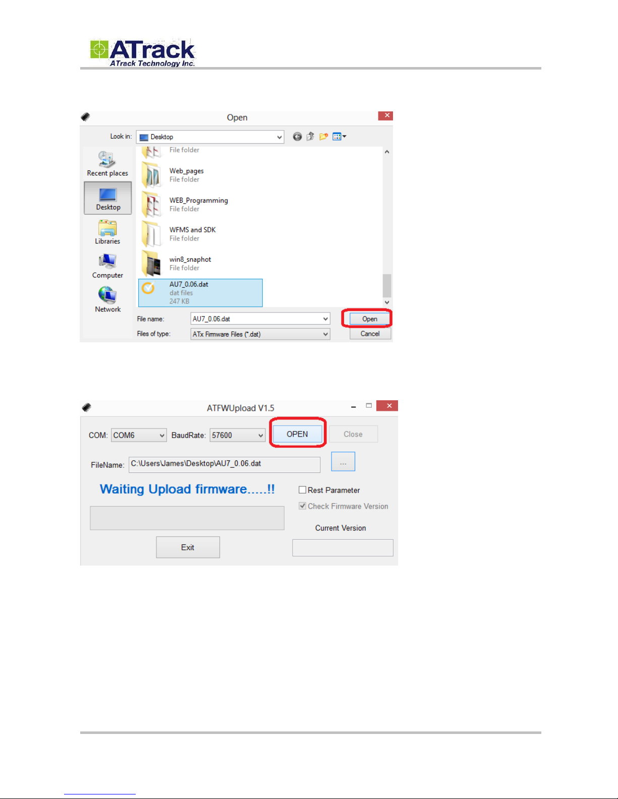
(6) Select the firmware file “AU7_0.06.dat”. Click on the [Open] button.
(7) Click on the [Open] button and power on the AU7. In this example, the AU7 is connected to a DC 12V
power supply.
Page 12
Confidential Document
© ATrack Technology Inc. All Rights Reserved. Page 12 of 15
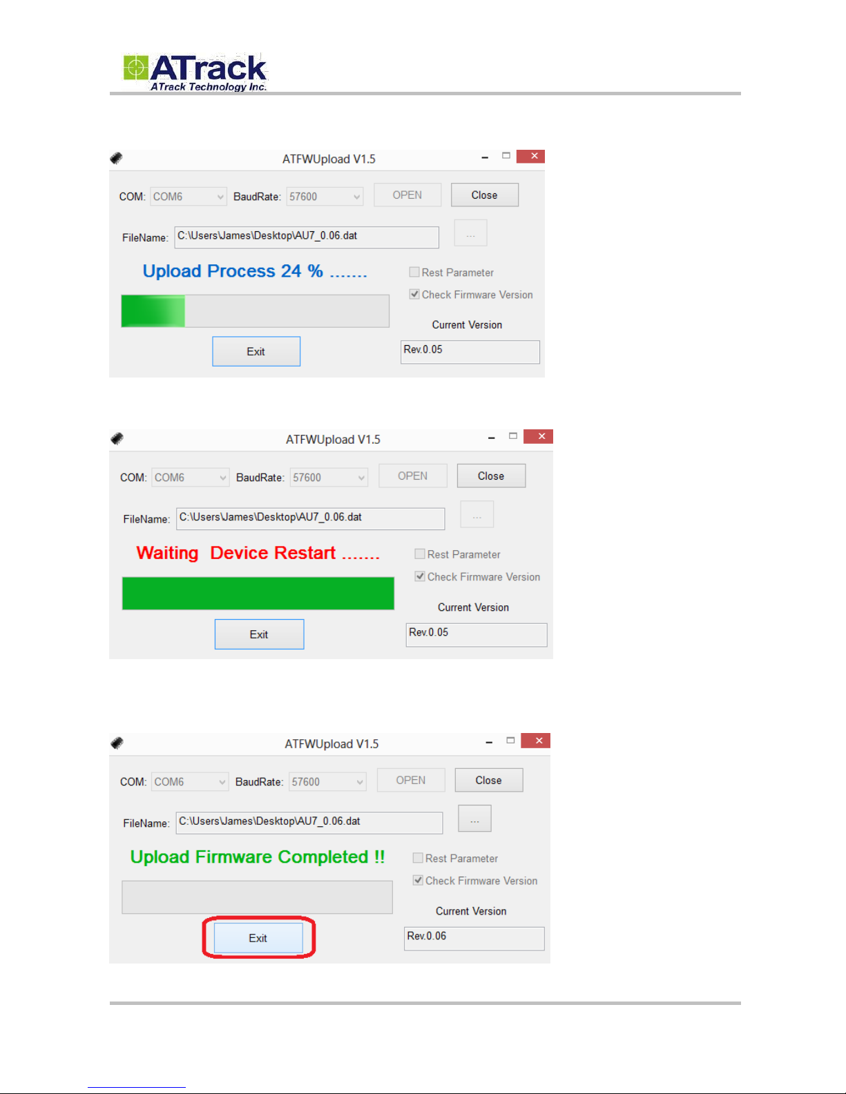
(8) The firmware is being uploaded.
(9) The AU7 is going to reboot after the firmware is uploaded.
(10) Once the upload process is completed, the current version shows the latest firmware version. Click on
the [Exit] button to exit the program.
Page 13
Confidential Document
© ATrack Technology Inc. All Rights Reserved. Page 13 of 15
44.. AATT$$IIOOCCGG CCoommmmaanndd RReeffeerreennccee
Command Description
The 16-pin female power I/O cable has a dark green wire which can be used to identify this unique
configurable I/O port. This port can be configured or queried through the AT$IOCG command. It is
recommended to disconnect the I/O connection prior to changing the I/O characteristic in order to avoid any
damage to the I/O port.
Syntax
Write Command
AT$IOCG=<IO1>
Response
$OK
Read Command
AT$IOCG=?
Response
$IOCG=<IO1>
Parameter Description
Parameters
Description
Data Type
Default
<IO1>
The default state of this port is OUT4. You may change it
to AN3 by typing AT$IOCG=2
1: Digital Output 4 (OUT4)
2: Analog Input 3 (AN3)
U8
1
Example
(1) Change Digital Output 4 to Analog Input 3
AT$IOCG=2
(2) Change Analog Input 3 to Digital Output 4
AT$IOCG=1
(3) Check the current state of the port
AT$IOCG=?
Remark
MEMO SERIAL SMS GPRS
Page 14
Confidential Document
© ATrack Technology Inc. All Rights Reserved. Page 14 of 15
55.. AAppppeennddiixx
55..11.. HHaarrddwwaarree SSppeecciiffiiccaattiioonn
Model Number
AU7(UA)
AU7(UE)
AU7(UG)
AU7(CV)
AU7(CS)
Dimensions (L x W x H)
100 x 65 x 26 mm
Weight
155g
Housing
Aluminum alloy
Operating Temperature
-30℃ ~ +80℃
Electrical Characteristics
Power Supply
8V ~ 40V DC (±20%)
Current Consumption
Operating Mode : Max.100mA@12V, Deep Sleep Mode: 7mA@12V
Backup Battery
Internal 3.7V 950mAh rechargeable Li-ion battery
Cellular Network Communication
Technology
UMTS/HSPA
CDMA2000 1xRTT
Frequency(MHz)
850/1900
900/2100
800/850/900
1700/1900/2100
800/1900MHz
Carrier Support
EU/APAC
US AT&T
World Wide
Verizon
Sprint
GSM/GPRS
Quad-Band 850/900/1800/1900MHz
N/A
Cellular Antenna
Internal Cellular antenna
SIM Card
1.8V/3V Micro SIM(3FF)
N/A
GPS
Receiver
66 Acquisition Channels, L1 Band, C/A Code, -165dBm sensitivity
Accuracy
3.0m CEP50 without SA
Data Acquisition Rate
1Hz
GPS Antenna
External GPS active antenna
GPS Data Buffer Capacity
8 MB
Accelerometer
3-Axis
Z,X,Y
Resolution / Sample Rate
±16g, Max / 400Hz
I/O Port
ACC
1 Positive Triggered
Digital Input
2 Positive, 3 Negative Triggered
Digital Output
3 Open-Collect Output (Max. sink current 300mA
MAX
)
Analog Input
2 (0 ~ 40VDC/0 ~ 5VDC, 12 bits resolution)
Multi-Purpose Port
1 software configurable as either a digital output or an analog input
1-Wire Interface
Supported up to 1 iButton and 4 temperature sensors
Buzzer Output
1
RS-232 Interface
1 (Configurable Baud Rate 1200bps~115200bps)
Audio Interface
1 (Speaker and Microphone)
Page 15

Confidential Document
© ATrack Technology Inc. All Rights Reserved. Page 15 of 15
55..22.. FFCCCC RReegguullaattiioonnss
This device complies with part 15 of the FCC Rules. Operation is subject to the following two conditions:
(1) This device may not cause harmful interference, and (2) this device must accept any interference
received, including interference that may cause undesired operation.
This device has been tested and found to comply with the limits for a Class B digital device, pursuant
to Part 15 of the FCC Rules. These limits are designed to provide reasonable protection against harmful
interference in a residential installation. This equipment can generate, use and radiate radio frequency
energy and, if not installed and used in accordance with the instructions, may cause harmful interference
to radio communications. However, there is no guarantee that interference will not occur in a particular
installation. If this equipment does cause harmful interference to radio or television reception, which can
be determined by turning the equipment off and on, the user is encouraged to try to correct the
interference by one or more of the following measures:
-Reorient or relocate the receiving antenna.
-Increase the separation between the equipment and receiver.
-Connect the equipment into an outlet on a circuit different from that to which the receiver is connected.
-Consult the dealer or an experienced radio/TV technician for help.
Changes or modifications not expressly approved by the party responsible for compliance could void the
user‘s authority to operate the equipment.
RF Exposure Information
This device meets the government’s requirements for exposure to radio waves.
This device is designed and manufactured not to exceed the emission limits for exposure to radio
frequency (RF) energy set by the Federal Communications Commission of the U.S. Government.
This device complies with FCC radiation exposure limits set forth for an uncontrolled environment. In
order to avoid the possibility of exceeding the FCC radio frequency exposure limits, human proximity to
the antenna shall not be less than 20cm (8 inches) during normal operation.
 Loading...