


Revision:
01
Revision Date:
2015/11/10
AL7
User Manual
ATrack Technology Inc.
3F., No. 88, Sec. 1, Neihu Rd., Neihu Dist.,
Taipei City 11493 Taiwan (R.O.C.)
Tel: +886-2-27975852
Fax: +886-2-27974030
http://www.atrack.com.tw

Confidential Document
Table of Contents
1. Notification .............................................................................................................................. 3
1.1. Disclaimer .................................................................................................................................... 3
1.2. Copyright ...................................................................................................................................... 3
1.3. Warning ........................................................................................................................................ 3
2. Introduction ............................................................................................................................. 4
3. System Architecture ............................................................................................................... 5
4. Installation ............................................................................................................................... 6
4.1. Package Content ......................................................................................................................... 6
4.2. SIM Card Installation .................................................................................................................... 6
4.3. Power I/O Connector ................................................................................................................... 7
4.4. USB Port and Driver Installation .................................................................................................. 8
4.5. LED Indicators ............................................................................................................................. 9
5. Configuration ........................................................................................................................ 10
5.1. Connect a Device Using HyperTerminal .................................................................................... 10
5.2. Connect a Device to a Remote Server ...................................................................................... 14
6. AT$IOCG Command Reference.......................................................................................... 15
6.1. Configure or Query I/O Pin Characteristics ............................................................................... 15
7. Firmware Upgrade ............................................................................................................... 16
8. Appendix ................................................................................................................................ 18
8.1. FCC Regulations ........................................................................................................................ 18
8.2. Hardware Specification .............................................................................................................. 19
Page 2 of 19

11.. NNoottiiffiiccaattiioonn
11..11.. DDiissccllaaiimmeerr
11..22.. CCooppyyrriigghhtt
11..33.. WWaarrnniinngg
Confidential Document
This document, and all other related products, such as device, firmware, and software, is developed by
ATrack Technology Inc. thoroughly. At the time of release, it is most compatible with specified firmware version.
Due to the functionalities of the devices are being developed and improved from time to time, the change in
the protocol, specification, and firmware functions are subjects to change without notice. ATrack Technology
Inc. is obligated to modify all the documentation without the limitation of time frame. A change notice shall be
released to ATrack Technology Inc. customers upon the completion of document modification.
ATrack Technology Inc. products are not intended to be used as life support or rescue equipments. ATrack
Technology Inc. is not liable for any loss or injury caused by using or referencing to any products. Any possible
means of using or integrating ATrack Technology Inc. products shall be avoided.
ATrack Technology Inc. holds all parts of intellectual rights applicable in the copyright laws in all the countries.
Any or all parts of this document shall not be exposed to non-authorized party without any form of approval
from ATrack Technology Inc. Any forms, including but not limited to oral, copy, or internet sharing, of releasing
or exposing information to an unauthorized party shall be prohibited. ATrack Technology Inc. reserves the
rights of litigation in the violation of such copyright laws.
Connecting the wire inputs can be hazardous to both the installer and your vehicle’s electrical system if not
done by an experienced installer. This document assumes you are aware of the inherent dangers of working
in and around a vehicle and have a working understanding of electricity.
Page 3 of 19

22.. IInnttrroodduuccttiioonn
Confidential Document
Congratulations on your purchase of the ATrack AL7 Vehicle/ Motorcycle Telematics device. The AL7 is
equipped with state of the art Mobile and GPS technology, providing the most reliable up to date tracking
information of your vehicle’s current position or movement status. In addition to this, vehicle/ motorcycle
tracking can be combined with a variety of customized events based on your needs.
Page 4 of 19

33.. SSyysstteemm AArrcchhiitteeccttuurree
Confidential Document
From the following diagram, the AL7 GPS receiver receives incoming signals from each orbiting satellite.
These signals consist of information such as satellite’s position and the time that the signal was transmitted by
each satellite. The receiver analyzes these data in order to determine how far away each satellite is and it
uses the triangulation method to calculate the vehicle’s exact position. Once the positioning data along with
other event data are gathered, they will be transmitted to the service center across a Mobile network (e.g.
GPRS/CDMA/UMTS) or via SMS. The communication is bidirectional, which means you can control the AL7
remotely across a Mobile network or via SMS.
System Architecture
Page 5 of 19

44.. IInnssttaallllaattiioonn
44..11.. PPaacckkaaggee CCoonntteenntt
44..22.. SSIIMM CCaarrdd IInnssttaallllaattiioonn
Confidential Document
When you open the package, please verify that you received the following device and accessories:
AL7 Device * 1
USB Cable * 1
The AL7 supports a SIM card with either of these two operating voltages: 1.8V (ISO/IEC 7816-3 class C) or
3V (ISO/IEC 7816-3 class B). To install a SIM card, please loosen the screws and remove the cover.
Page 6 of 19

44..33.. PPoowweerr II//OO CCoonnnneeccttoorr
Power I/O Connector
Pin#
Function
Color
Designation
Note
1
Main power input
Red
PWR
DC 6V~32V DC input
2
Power ground
Black
GND
3
ACC Input
Yellow
ACC
Ignition status positive trigger input
4**
General Input1 (Default)
1-Wire Protocol Input *
Green
IN1/1W
Negative trigger input
1-Wire Data input
5**
General Input2
General Output1 (Default)
Analog Input1
Brown
IN2/O1/AI
Positive trigger input
Open collector output (Max.300mA)
Analog input (DC3V~40V)
6**
General Input3
General Output2 (Default)
Gray
IN3/O2
Negative trigger input
Open collector output (Max.300mA)
Confidential Document
The following table describes the function of each bare wire.
* The 1-Wire® Protocol supports up to three 1-Wire™ devices simultaneously, which means you can have
one (iButton® , DS1990A) and two 1-Wire™ temperature sensor probes (DS18B20)
** You may configure the AT$IOCG command to change these specific I/O pins to any of those functions
mentioned as above. Note: Please do not connect a positive voltage to any output pin!!!
Page 7 of 19

44..44.. UUSSBB PPoorrtt aanndd DDrriivveerr IInnssttaallllaattiioonn
USB Port
Confidential Document
The following figure shows the position of USB port on device.
Double click the USB driver VCP_V1.3.1_Setup/ VCP_V1.3.1_Setup_x64. Then, click the Finish button to
complete the process.
Page 8 of 19
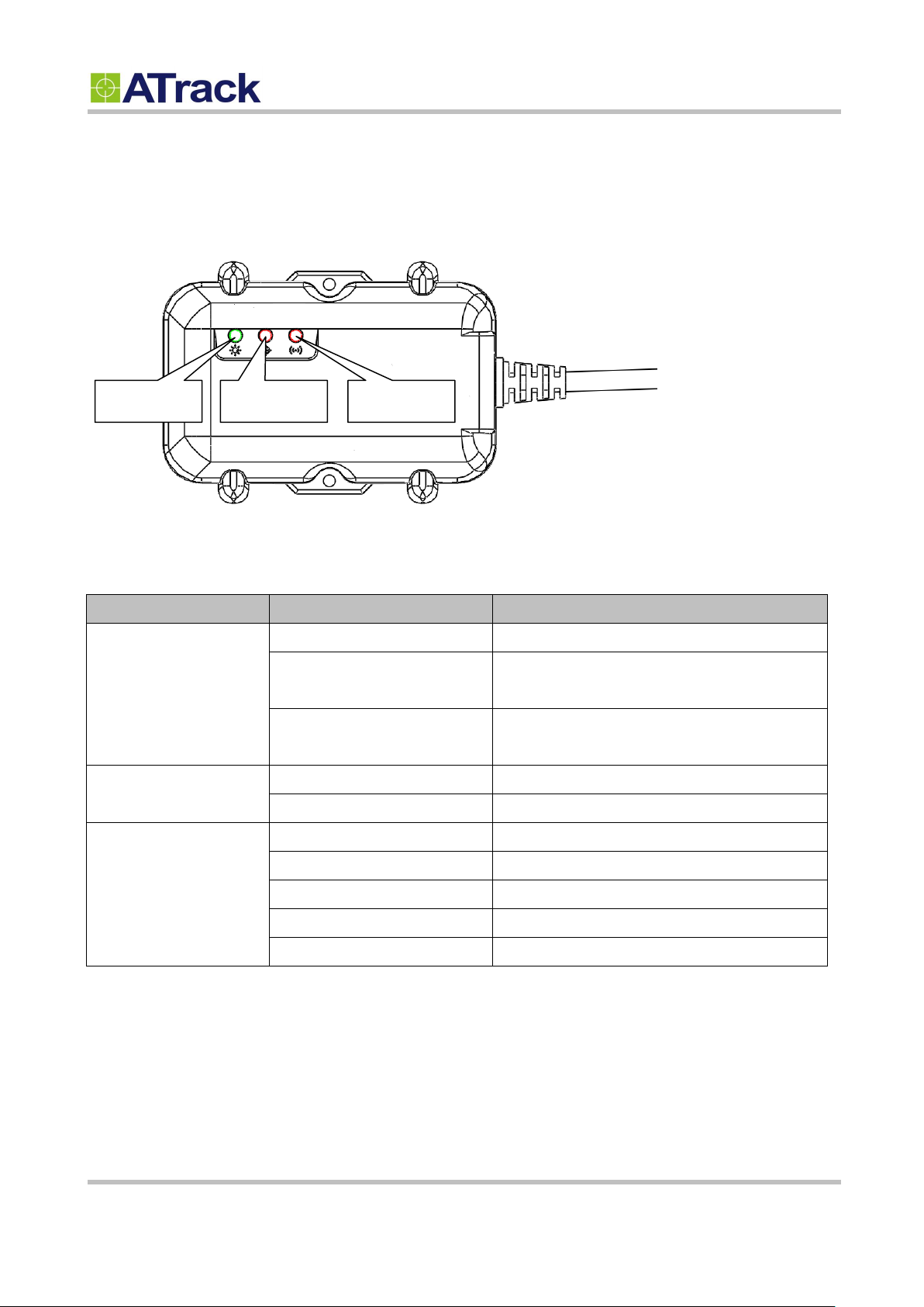
44..55.. LLEEDD IInnddiiccaattoorrss
LED
Indication
Description
PWR (Green)
Solid On
In full operation mode
1 blink (0.1 sec.) in every 10
sec.
In sleep mode
1 sec. On, 1 sec. Off
GPS module off, External power lost, running on
backup battery
GPS (Red)
0.7 sec. On, 0.7 sec. Off
Searching for GPS signal
Solid On
Position get fixed
GSM (Red)
Off
GSM module off
0.7 sec. On, 0.7 sec. Off
Searching for GSM signal
0.2 sec. On, 2 sec. Off
Registered to GSM network
2 blinks in every 2 sec.
Connected to GPRS network
Continuous blinking
SIM PIN Error
PWR
GPS
GSM
Confidential Document
The following figure shows the location of the device LEDs.
Note: In the case of SIM PIN Error, the device will check the AT$SPIN every 10 minutes and try to
access the SIM again. The PIN will be validated 3 times and if it fails the last attempt, including the first
inserting time, the SIM card will be locked. Once the SIM is locked, you need to contact your GSM
carrier for the PUK in order to unlock the SIM card using your cell phone.
Page 9 of 19
55.. CCoonnffiigguurraattiioonn
55..11.. CCoonnnneecctt aa DDeevviiccee UUssiinngg HHyyppeerrTTeerrmmiinnaall
Confidential Document
You may be able to explore great features on the AL7 through AT commands. The commands can be sent to a
device via USB, SMS or Mobile network (e.g. GPRS/CDMA/UMTS). The following diagram shows how to
configure a device with Hyper terminal via USB.
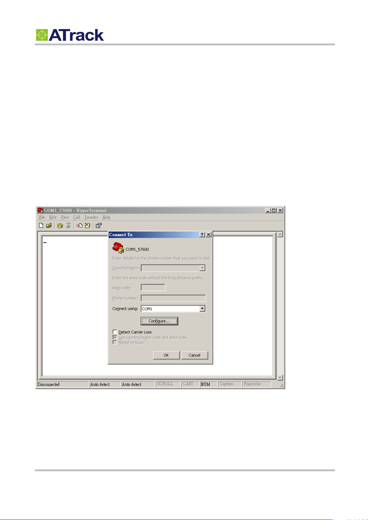
The following example shows how to connect the AL7 through HyperTerminal. You may use other popular
terminal emulators such as Putty or Tera Term Pro to establish a console session with the AL7.
(1) Run HyperTerminal and select the correct COM port and click on the [Configure…] button.
Page 10 of 19

Bits per second: 57600
Data Bits: 8
Parity: None
Stop Bits: 1
Flow Control: None
Confidential Document
(2) Port Settings should be as follows. Click on the [OK] button to close the Properties window.
(3) Click on [File][Properties]
Page 11 of 19
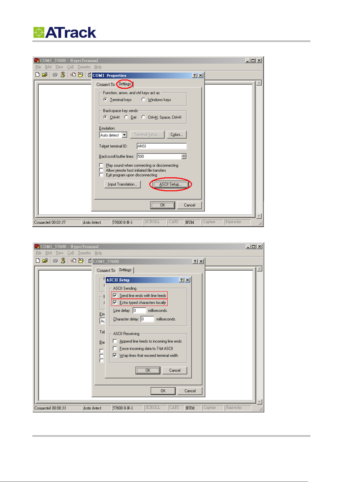
(4) Click on the [Settings] tab and click on the [ASCII Setup…] button.
Confidential Document
(5) Check the following options and click on the [OK] button.
Page 12 of 19
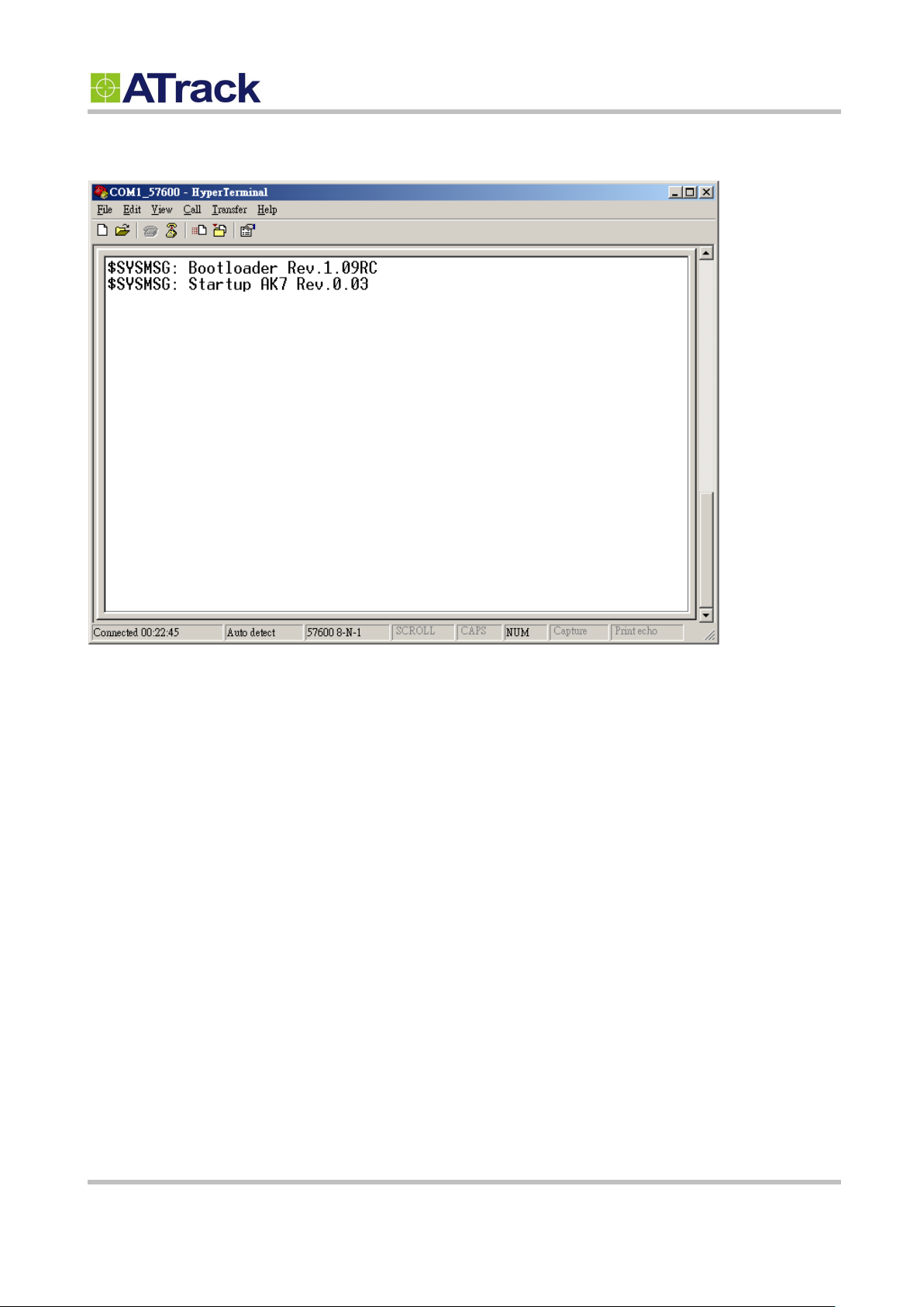
Confidential Document
(6) Power ON the device and the startup message will be displayed on the screen. You may type some AT
commands to query the device afterwards. Please refer to the ATrack Protocol Document for details.
Page 13 of 19

55..22.. CCoonnnneecctt aa DDeevviiccee ttoo aa RReemmoottee SSeerrvveerr
Confidential Document
The GPRS or UMTS connection can either be enabled by typing the AT$GPRS command. Once enabled, the
ATrack ServerTool is then installed on a Windows PC in order to communicate with the AL7 remotely via a
GPRS or UMTS network. The ServerTool is a remote server application, which is mainly used for parsing data
by translating binary formats into readable formats or other testing purposes. Port forwarding is required if the
PC is located behind a Broadband router or any other firewall device or if it has third-party firewall software
installed. The communication is bidirectional, which means you can issue any AT command to the AL7 by
clicking the Send button. Please refer to the following snapshot and the Port forwarding website:
http://portforward.com/ for details.
Page 14 of 19

66.. AATT$$IIOOCCGG CCoommmmaanndd RReeffeerreennccee
66..11.. CCoonnffiigguurree oorr QQuueerryy II//OO PPiinn CChhaarraacctteerriissttiiccss
Command Description
This command is used to set or query the I/O port characteristics of the AL7. It is recommended to disconnect all I/O
connections prior to changing the I/O characteristic in order to avoid damage to the I/O port.
Syntax
Write Command
AT$IOCG=<IO1>,<IO2>,<IO3>
Response
$OK
Read Command
AT$IOCG=?
Response
$IOCG=<IO1>,<IO2>,<IO3>
Parameter Description
Parameters
Description
Data Type
Default
<IO1>
1: Input1
4: 1-Wire Protocol
U8
1
<IO2>
1: Input 2
2: Output 1
3: Analog Input
U8
2
<IO3>
1: Input 3
2: Output 2
U8
2
Example
(1) Change all ports to inputs:
AT$IOCG=1,1,1
(2) Change Input1 to 1-Wire Protocol
AT$IOCG=4,2,2
(3) Change IO1 and IO3 to inputs, and IO2 to analog input:
AT$IOCG=1,3,1
Remark
MEMO SERIAL SMS GPRS
Confidential Document
Page 15 of 19

77.. FFiirrmmwwaarree UUppggrraaddee
Confidential Document
The device firmware can be upgraded via USB or through the FTP protocol. Following is an example of
firmware upgrade via USB.
(1) Make AL7 connecting to hyper terminal and execute AT$FWDL
(2) Click on [Transfer] -> [Send File]
Page 16 of 19

(3) Choose Firmware file and Ymodem for Protocol.
(4) From the following snapshot, the data is being read out.
Confidential Document
(5) Click the firmware is updated successfully by AT$INFO=?.
Page 17 of 19

88.. AAppppeennddiixx
88..11.. FFCCCC RReegguullaattiioonnss
Confidential Document
This device complies with part 15 of the FCC Rules. Operation is subject to the following two
conditions: (1) This device may not cause harmful interference, and (2) this device must accept any
interference received, including interference that may cause undesired operation.
This device has been tested and found to comply with the limits for a Class B digital device, pursuant
to Part 15 of the FCC Rules. These limits are designed to provide reasonable protection against harmful
interference in a residential installation. This equipment can generate, use and radiate radio frequency
energy and, if not installed and used in accordance with the instructions, may cause harmful interference
to radio communications. However, there is no guarantee that interference will not occur in a particular
installation. If this equipment does cause harmful interference to radio or television reception, which can
be determined by turning the equipment off and on, the user is encouraged to try to correct the
interference by one or more of the following measures:
-Reorient or relocate the receiving antenna.
-Increase the separation between the equipment and receiver.
-Connect the equipment into an outlet on a circuit different from that to which the receiver is connected.
-Consult the dealer or an experienced radio/TV technician for help.
Changes or modifications not expressly approved by the party responsible for compliance could void the
user‘s authority to operate the equipment.
RF Exposure Information
This device meets the government’s requirements for exposure to radio waves.
This device is designed and manufactured not to exceed the emission limits for exposure to radio
frequency (RF) energy set by the Federal Communications Commission of the U.S. Government.
This device complies with FCC radiation exposure limits set forth for an uncontrolled environment. In
order to avoid the possibility of exceeding the FCC radio frequency exposure limits, human proximity to
the antenna shall not be less than 20cm (8 inches) during normal operation.
Page 18 of 19

88..22.. HHaarrddwwaarree SSppeecciiffiiccaattiioonn
Model Number
AL7(2G)
AL7(UA)
AL7(UE)
AL7(UG)
AL7(CV)
AL7(CS)
Dimensions (L x W x H)
88 x 65 x 25 mm
Weight
149 g
Housing
Flame Retardant ABS(UL 94 V-0), IP67 Water Proof
Operating Temperature
(w/o battery)
-40°C ~ 85°C (-40°F ~ 185°F)
Electrical Characteristics
Power Supply
6V ~ 30V DC
Current Consumption
Operating : Max.70mA@12V, Deep Sleep Mode : 2.17uA@12V
Cellular Network Communication
Technology
GSM/GPRS
WCDMA/HSPA
CDMA2000 1xRTT
Frequency(MHz)
850/900
1800/1900
850/1900
900/2100
800/850
900/1700
1900/2100
800/1900
Carrier Support
WorldWide
USA/Canada
EU/APAC
WorldWide
Verizon
Sprint
GSM/GPRS
Quad-band
850/1900
900/1800
Quad-band
N/A
Cellular Antenna
Internal Cellular antenna
SIM Card
1.8V/3V Mini SIM(2FF)
N/A
GNSS
Receiver
56 Channels, -161dBm (GPS) /-158 dBM(GLONASS) Tracking sensitivity
Accuracy
2.5m CEP (GPS) / 4.0 m CEP (GLONASS)
Data Acquisition Rate
1Hz
Antenna
Internal GPS/ GLONASS antenna
GPS Data Buffer Capacity
2 MB
Accelerometer
3-Axis
Z,X,Y
Resolution/Sample Rate
±16g, 400Hz
Device I/O port
ACC Input
1 Positive
*Digital Input
1 Positive and 1 Negative triggered
*Digital Output(Option)
2 Open-collector output
*Analog Input(Option)
3~40VDC, 12 bits resolution
*1-Wire® Interface
Support up to 1 Dallas-Key (iButton®) and 2 temperature sensors
USB
1 micro USB inside the case for device configuration
Standard Accessories
USBCable
Length 1.2m
Backup Battery
Internal 3.7V 920mAh Rechargeable Lithium-ion Battery
Confidential Document
Page 19 of 19
 Loading...