

Page 1

SW550X Industrial Wireless Serial
Device Server Series
User’s Manual
v. 1.1
April 2013
Page 2

Atop Industrial Wireless Serial Device Server Series
SW550X
User Manual V 1.1
Tel:
886-3-5508137
Fax:
886-3-5508131
www.atop-tech.com
www.atop.com.tw
Important Announcement
The information contained in this document is the sole property of Atop Technologies, Inc. and
is supplied for the sole purpose of operation and maintenance of Atop Technologies, Inc.
products. No part of this publication is to be used for any other purposes, and is not to be
reproduced, copied, disclosed, transmitted, stored in a retrieval system, or translated into any
human or computer language, in any form, by any means, in whole or in part, without the prior
explicit written consent of Atop Technologies, Inc., offenders will be held liable for damages. All
rights, including rights created by patent grant or registration of a utility model or design, are
reserved.
Disclaimer
We have checked the contents of this manual for agreement with the hardware and software
described. Since deviations cannot be precluded entirely, we cannot guarantee full agreement.
However, the data in this manual is reviewed regularly and any necessary corrections included
in subsequent editions. Suggestions for improvement are welcomed. All other product names
referenced herein are registered trademarks of their respective companies.
Published and Printed by
Atop Technologies, Inc.
2F, No. 146, Sec. 1, Tung-Hsing Rd.
Jubei, Hsinchu 30261
Taiwan, R.O.C.
Copyright © 2011 Atop Technologies, Inc. All rights reserved. Technical data is subject to
change.
ii
Page 3

Atop Industrial Wireless Serial Device Server Series
SW550X
User Manual V 1.1
Contents
Preface ............................................................................................................ 1
1 Introduction ............................................................................................. 4
1.1 Product Overview ................................................................................... 4
1.2 Features..................................................................................................... 5
2 Getting Started ........................................................................................ 6
2.1 Inside the Package ................................................................................. 6
2.2 Front & Power Panels ............................................................................ 7
2.3 Serial Pin Assignments ....................................................................... 10
2.3.1 DB9 ........................................................................................................ 10
2.3.2 Terminal Block ................................................................................... 10
2.4 First Time Installation .......................................................................... 11
2.4 User Interface Overview ...................................................................... 12
2.6 Factory Default Settings ..................................................................... 14
3 Configuration ........................................................................................ 16
3.1 Administrator Login ............................................................................. 16
3.2 Operation Mode ..................................................................................... 18
3.3 Overview ................................................................................................. 19
3.3.1 Wireless Status .................................................................................. 20
3.3.2 Site Monitor ........................................................................................ 21
3.4 Network Settings................................................................................... 23
3.5 Wireless ................................................................................................... 26
3.5.1 Profiles ................................................................................................. 26
3.5.2 Basic Settings .................................................................................... 26
3.7.1 Advanced Settings ............................................................................ 33
3.8 Serial ........................................................................................................ 34
3.8.1 COM Port Overview .......................................................................... 34
iii
Page 4

Atop Industrial Wireless Serial Device Server Series
SW550X
User Manual V 1.1
3.8.2 COM Configuration ........................................................................... 35
3.8.3 COM Configuration: Advanced Settings ..................................... 36
3.9 SNMP/ALERT Settings ........................................................................ 39
3.10 E-mail Settings ................................................................................... 41
3.11 Log Settings ....................................................................................... 42
3.11.1 System Log Settings ........................................................................ 42
3.11.2 COM Log Settings ............................................................................. 43
3.11.3 Event Log ............................................................................................ 44
3.11.4 COM Datalog ...................................................................................... 45
3.12 System Setup ..................................................................................... 46
3.12.1 Date/Time Settings ............................................................................ 46
3.12.2 Admin Settings .................................................................................. 47
3.12.3 Firmware Upgrade............................................................................. 48
3.12.4 Backup/Restore Setting ................................................................... 49
3.12.5 Management List ............................................................................... 50
3.12.6 Ping ....................................................................................................... 51
3.13 Reboot and Restore Default Settings .......................................... 52
4 Link Modes and Applications .............................................................. 53
4.1 Link Mode Configuration .................................................................... 53
4.1.1 Link Mode: Configure SW550X as a TCP Server ...................... 54
4.1.2 Link Mode: Configure SW550X as a TCP Client ........................ 59
4.1.3 Link Mode: Configure SW550X in UDP........................................ 63
4.2 Link Mode Applications ...................................................................... 66
4.2.1 TCP Server Application: Enable Virtual COM ............................ 66
4.2.2 TCP Server Application: Enable RFC 2217 ................................ 67
4.2.3 TCP Client Application: Enable Virtual COM ............................. 67
4.2.4 TCP Client Application: Enable RFC 2217 .................................. 68
4.2.5 TCP Server Application: Configure SW550X as a Pair
Connection Master .............................................................................................. 68
iv
Page 5

Atop Industrial Wireless Serial Device Server Series
SW550X
User Manual V 1.1
4.2.6 TCP Client Application: Configure SW550X as a Pair
Connection Slave ................................................................................................ 70
4.2.7 TCP Server Application: Enable Reverse Telnet ...................... 71
4.2.8 UDP Application: Multi-Point Pair Connection .......................... 72
4.2.9 TCP Server Application: Multiple TCP Connections ............... 74
4.2.10 TCP Server Application: Multi-Point TCP Pair Connections . 75
4.3 Wireless Topology ................................................................................ 76
4.3.1 Configure SW550X as a Wireless Ad-Hoc Peer ........................ 76
4.3.2 Configure SW550X as a Wireless Client in the Infrastructure
mode (PSK) ........................................................................................................... 78
4.3.3 Click -2-Go .......................................................................................... 79
4.3.4 Configure SW550X as a Wireless Client in the Infrastructure
mode (PEAP-MSCHAPv2) ................................................................................. 80
5 VCOM Installation & Troubleshooting................................................. 82
5.1 Enabling VCOM ..................................................................................... 82
5.1.1 VCOM driver setup ............................................................................ 85
5.1.2 Limitation ............................................................................................ 85
5.1.3 Installation .......................................................................................... 86
5.1.4 Uninstalling ......................................................................................... 86
5.2 Enable VCOM Serial device servers and select VCOM in
Windows ............................................................................................................ 87
5.2.1 Enable VCOM in Serial device servers ........................................ 87
5.2.2 Running Serial/IP in Windows ....................................................... 88
5.2.3 Configuring VCOM Ports ................................................................. 91
5.3 Exceptions .............................................................................................. 94
5.4 Using Serial/IP Port Monitor ............................................................ 100
5.4.1 Opening the Port Monitor ............................................................. 100
5.4.2 The Activity Panel ........................................................................... 100
5.4.3 The Trace Panel ............................................................................... 102
5.5 Serial/IP Advanced Settings............................................................. 103
v
Page 6

Atop Industrial Wireless Serial Device Server Series
SW550X
User Manual V 1.1
5.5.1 Using Serial/IP with a Proxy Server ........................................... 105
6 Specifications ..................................................................................... 106
6.1 Hardware ............................................................................................... 106
6.2 Software Specifications .................................................................... 116
Emergency System Recovery ................................................................... 117
Warranty ..................................................................................................... 119
vi
Page 7

Preface
Purpose of the Manual
This manual supports you during the installation and configuring of the SW550X Series only,
as well as it explains some technical options available with the mentioned product. As such, it
contains some advanced network management knowledge, instructions, examples, guidelines
and general theories designed to help users manage this device and its corresponding
software; a background in general theory is a must when reading it. Please refer to the
Glossary for technical terms and abbreviations.
Who Should Use This User Manual
This manual is to be used by qualified network personnel or support technicians who are
familiar with network operations; it might be useful for system programmers or network
planners as well. This manual also provides helpful and handy information for first time users.
For any related problems please contact your local distributor, should they be unable to assist
you, please redirect your inquiries to www.atop.com.tw or www.atop-tech.com .
Supported Platform
This manual is designed for the SW550X Series and that model only.
Warranty Period
We provide a 5 year limited warranty for SW550X Series.
Manufacturers Federal Communication Commission Declaration of
Conformity Statement
Model: SW550X Series
NOTE: This equipment has been tested and found to comply with the limits for a Class A
digital device, pursuant to Part 15 of the FCC Rules. These limits are designed to provide
reasonable protection against harmful interference when the equipment is operated in a
commercial environment. This equipment generates, uses, and can radiate radio frequency
energy and, if not installed and used in accordance with the instruction manual, may cause
harmful interference to radio communications. Operation of this equipment in a
residential area is likely to cause harmful interference in which case the user will be required to
correct the interference at his expense.
This device complies with Part 15 of the FCC Rules. Operation is subject to the following
1
Page 8

Atop Industrial Wireless Serial Device Server Series
SW550X
User Manual V 1.1
※
This device is restricted to indoor use when operated in the 5.15 to 5.25 GHz frequency range
use. FCC requires this product to be used indoors for the frequency range 5.15 to 5.25 GHz to
reduce the potential for harmful interference to co-channel Mobile Satellite systems.
two conditions:
1 This device may not cause harmful interference, and
2 This device must accept any interference received, including interference that may
cause undesired operation.
This device and its antenna(s) must not be co-located or operating in conjunction with any
other antenna or transmitter.
FCC Caution: Any changes or modifications not expressly approved by the party responsible
for compliance could void the user's authority to operate this equipment.
For product available in the USA/Canada market, only channel 1~11 can be operated.
Selection of other channels is not possible.
FCC Radiation Exposure Statement:
This equipment complies with FCC radiation exposure limits set forth for an uncontrolled
environment. This equipment should be installed and operated with minimum distance 20cm
between the radiator & your body.
European Community, Switzerland, Norway, Iceland, and Liechtenstein
Model: SW550X Series
Declaration of Conformity with regard to the R&TTE Directive 1999/5/EC
This equipment is in compliance with the essential requirements and other relevant provisions
of 1999/5/EC.
The following standards were applied:
EMC—EN 301.489-1 v1.4.1; EN 301.489-17 v1.2.1
Health & Safety—EN60950-1: 2001; EN 50385: 2002
Radio—EN 300 328 v 1.7.1; EN 301.893 v 1.5.1
The conformity assessment procedure referred to in Article 10.4 and Annex III of Directive
1999/5/EC has been followed.
This device also conforms to the EMC requirements of the Medical Devices Directive
93/42/EEC.
Note This equipment is intended to be used in all EU and EFTA countries. Outdoor use may be
restricted to certain frequencies and/or may require a license for operation. For more details,
contact Cisco Corporate Compliance.
2
Page 9

Atop Industrial Wireless Serial Device Server Series
SW550X
User Manual V 1.1
European Union
This system has been evaluated for RF exposure for Humans in reference to the ICNIRP
(International Commission on Non-Ionizing Radiation Protection) limits. The evaluation was
based on the EN 50385 Product Standard to Demonstrate Compliance of Radio Base stations
and Fixed Terminals for Wireless Telecommunications Systems with basic restrictions or
reference levels related to Human Exposure to Radio Frequency Electromagnetic Fields from
300 MHz to 40 GHz. The minimum separation distance from the antenna to general bystander
is 20cm (7.9 inches).
UL Notice for Power supplier
The SW550X Series products are intended to be supplied by a Listed Power Unit marked with
“LPS” (Limited Power Source), or “Class 2” and output rate of 9~48 VDC, 1.0 A minimum, or
use the recommended power supply listed in “Optional Accessories”.
3
Page 10
Atop Industrial Wireless Serial Device Server Series
SW550X
User Manual V 1.1
1 Introduction
1.1 Product Overview
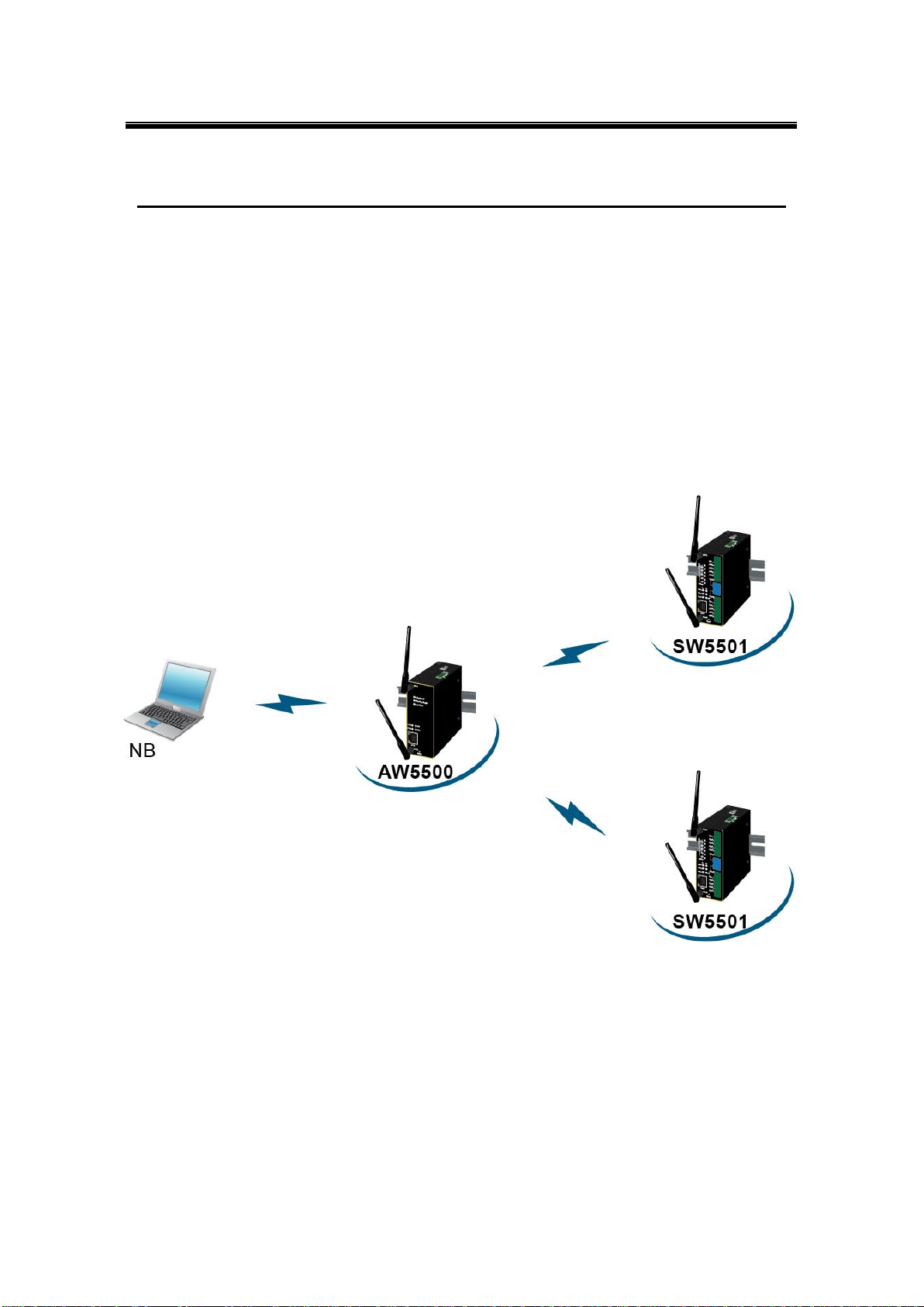
The SW550X Industrial Wireless Serial Device Server is the newest in our wireless series
designed to provide connectivity to clients and serial devices creating a complete solution for
your wireless networking.
As an example, you can connect serial devices to our Wireless Serial Server and connect
these two to a Wireless device; this example illustrates how to connect serial devices to a
local area network or a backbone network, Fig. 1. 1. The SW550X series provide several
functionalities to support mobile and wireless networking.
Fig. 1. 1
4
Page 11

Atop Industrial Wireless Serial Device Server Series
SW550X
User Manual V 1.1
1.2 Features
The SW550X Series is our latest addition to our Industrial Wireless products; its small size but
powerful architecture makes it a perfect choice for industrial/manufacturing needs in which
size is a decisive factor. It rewards our customers with superb connectivity withstanding all the
harshness in your environment of choice. Among its many characteristics, we could mention:
5 GHz frequency support to reduce interference on 2.4 GHz with other wireless devices.
Dual antenna design that offers better wireless coverage and reduces wireless blind
spots.
Caution
Beginning from here there will be extreme caution exercised.
Never install or work on electrical or cabling during periods of lighting activity. Never
connect or disconnect power when hazardous gases are present.
WARNING: Disconnect the power and allow to cool 5 minutes before touching.
5
Page 12

Atop Industrial Wireless Serial Device Server Series
SW550X
User Manual V 1.1
Item
Quantity
Description
SW550X
1
Industrial Wireless Serial Device Server
Antenna
2
3~5 dBi antenna
TB3
1
3-pin 5.08mm lockable Terminal Block
TB5
1
5-pin 5.08mm lockable Terminal Block (SW5501-TB/SW5501-Sis only)
TB5
2
5-pin 5.08mm lockable Terminal Block (SW5502-TB/SW5502-Sis only)
Installation Guide + Warranty Card
1
Din Rail Kit
1
Already mounted to the device
CD (Utilities)
1
Inside you will find:
User’s Manual
Installation Guide
Serial Manager© Utility
2 Getting Started
2.1 Inside the Package
Inside the product purchased you will find the following items:
Table 2. 1
Note: Please notify your sales representative if any of the above items is missing or damaged in any form upon
delivery. If your sales representative is unable to satisfy your enquiries, please contact us directly.
6
Page 13
Atop Industrial Wireless Serial Device Server Series
SW550X
User Manual V 1.1
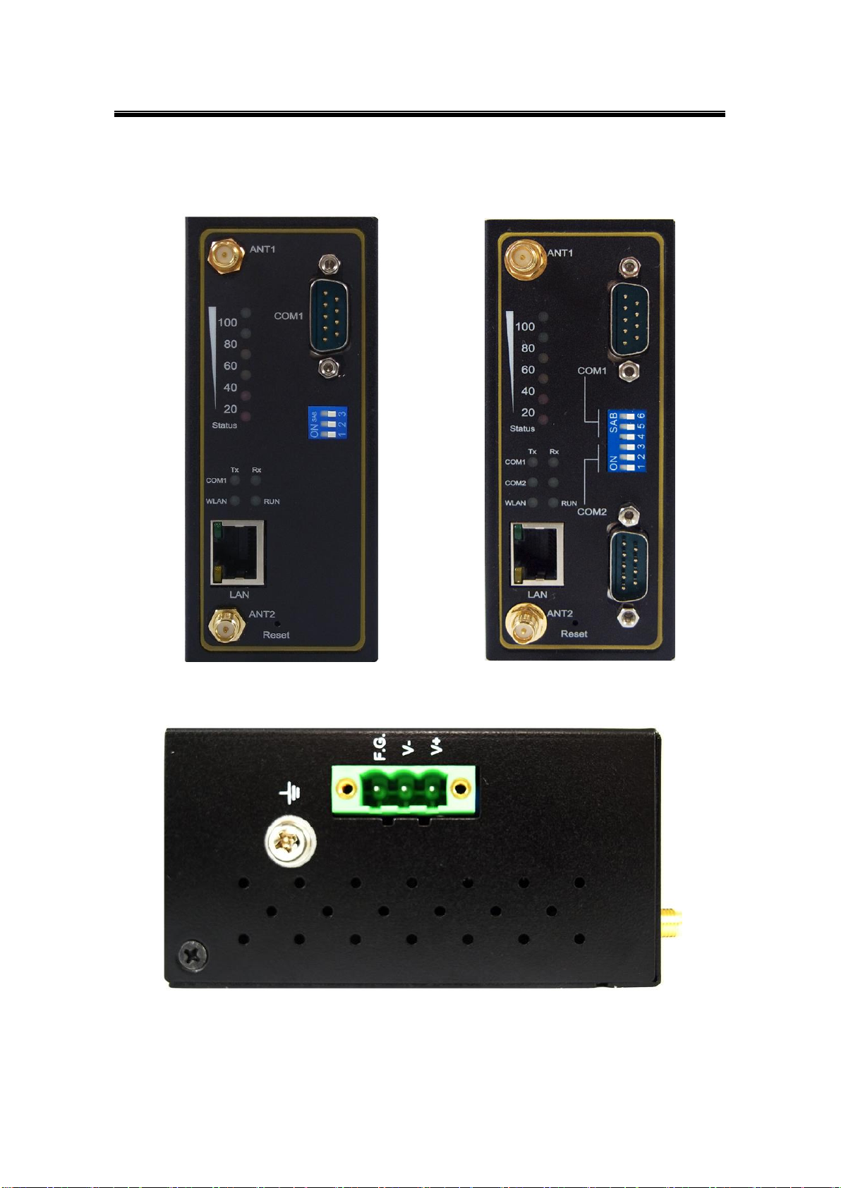
`
Fig. 2. 1
Fig. 2. 2
Fig. 2. 3
2.2 Front & Power Panels
The Front, and Power panels, are as follow:
7
Page 14

Atop Industrial Wireless Serial Device Server Series
SW550X
User Manual V 1.1
Fig. 2. 4
Fig. 2. 5
Model
Figure
SW5501
Fig. 2. 1
SW5502
Fig. 2. 2
SW5501-TB / SW5501-Sis
Fig. 2. 4
SW5502-B / SW5502-Sis
Fig. 2. 5
Note: the following front panel figures correspond to the following models.
8
Page 15
Atop Industrial Wireless Serial Device Server Series
SW550X
User Manual V 1.1
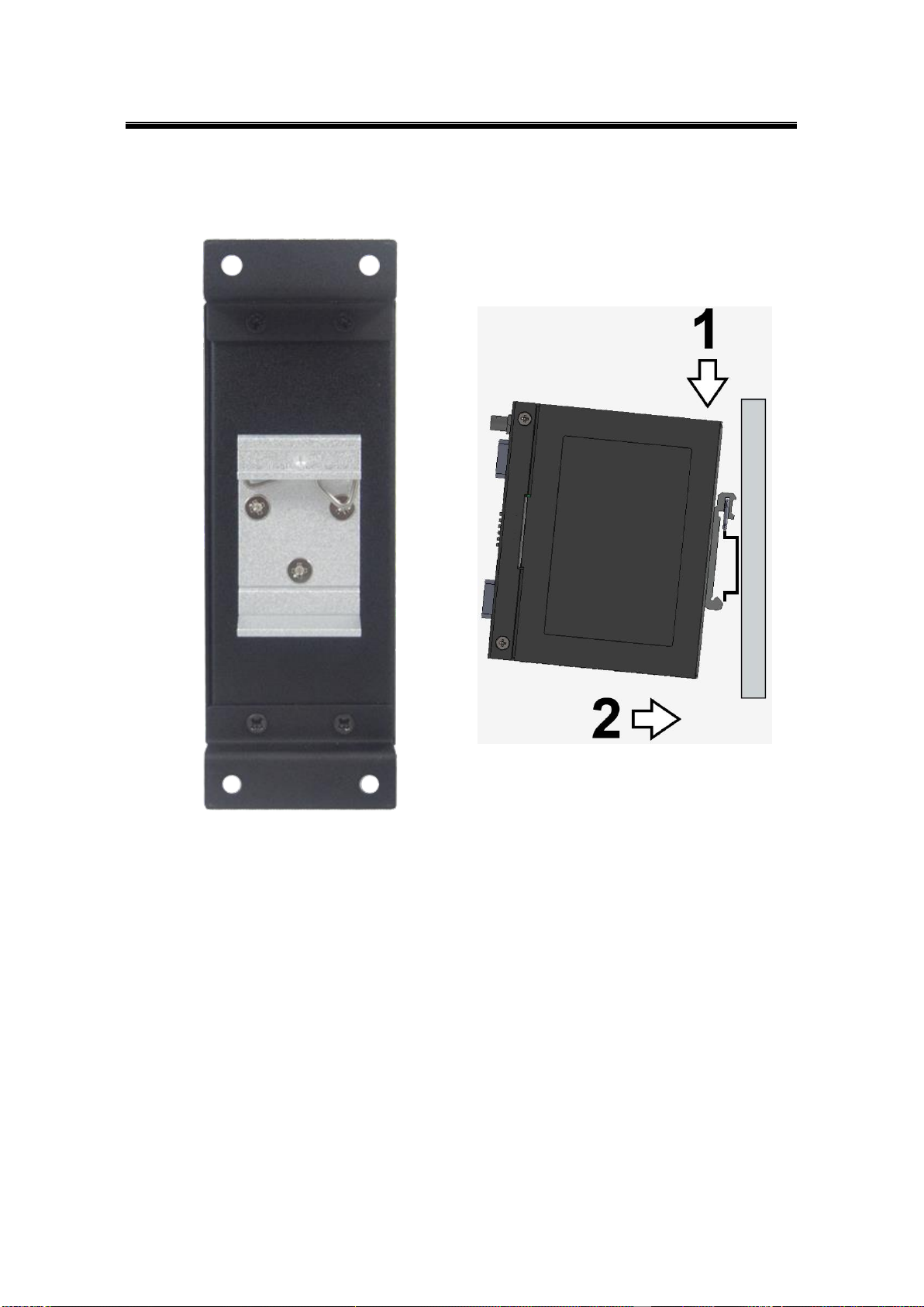
Fig. 2. 6
Fig. 2. 7
The Rear panel (where you can mount the device on a rail or to the wall), looks as in Fig. 2. 6,
a simple mounting instruction is given on Fig. 2. 7.
9
Page 16

Atop Industrial Wireless Serial Device Server Series
SW550X
User Manual V 1.1
Pin#
RS-232
Full Duplex
RS-422/4-Wire RS-485
Half Duplex
2-Wire RS-485
Half Duplex
1
DCD
N/A
N/A
2
RXD
TXD+
N/A (reserved)
3
TXD
RXD+
DATA+
4
DTR
N/A
N/A
5
SG (Signal Ground)
SG (Signal Ground)
SG (Signal Ground)
6
DSR
N/A
N/A
7
RTS
RXD-
DATA-
8
CTS
TXD-
N/A (reserved)
9
RI
N/A
N/A
Pin#
RS-232
Full Duplex
RS-422/4-Wire RS-485
Half Duplex
2-Wire RS-485
Half Duplex
1
RxD
T+
NC
2
CTS
T-
NC
3
TxD
R+
DATA+
4
RTS
R-
DATA-
5
SG (Signal Ground)
SG (Signal Ground)
SG (Signal Ground)
2.3 Serial Pin Assignments
2.3.1 DB9
2.3.2 Terminal Block
10
Page 17

Atop Industrial Wireless Serial Device Server Series
SW550X
User Manual V 1.1
2.4 First Time Installation
Before installing the device, please adhere to all safety procedures described below, Atop will
not be held liable for any damages to property or personal injuries resulting from the
installation or overall use of the device. Do not attempt to manipulate the product in any
way if unsure of the steps described here2, in such cases please contact your dealer
immediately.
1 Prepare the necessary cables, DC adapter, power cord, LAN cable, serial cable, etc.; do
not connect the unit yet.
2 Install both antennas to the SMA connectors.
3 Proceed then to plug the power source to the unit, starting from the ground and then the
terminal block.
4 Place the device in the desired location and connect it to the LAN via an Ethernet cable
with an RJ45 connector.
5 Connect your computer to the LAN network. Default configurations will be addressed
later on Sec. 2.5.
Note2: remember to please consult your Hardware Installation Guide when attempting an installation. Also, please
follow all safe procedures when doing so.
11
Page 18
Atop Industrial Wireless Serial Device Server Series
SW550X
User Manual V 1.1
2.4 User Interface Overview
The SW550X Series is designed as a Wireless Client with the ability to choose between two
different WLAN and LAN networks, its user interface is designed intuitively for ease of use to
suit the customer needs. The web configuration appears as follows, Fig. 2. 8.
Fig. 2. 8
12
Page 19

Atop Industrial Wireless Serial Device Server Series
SW550X
User Manual V 1.1
On the left side, a menu-tree appears with all the modes and options available (Fig. 2. 9), while
on the right side of your screen the contents of each mode/option will be displayed in a
graphical state. For more information on each selection please refer to each option’s Section
throughout the manual.
Fig. 2. 9
13
Page 20
Atop Industrial Wireless Serial Device Server Series
SW550X
User Manual V 1.1
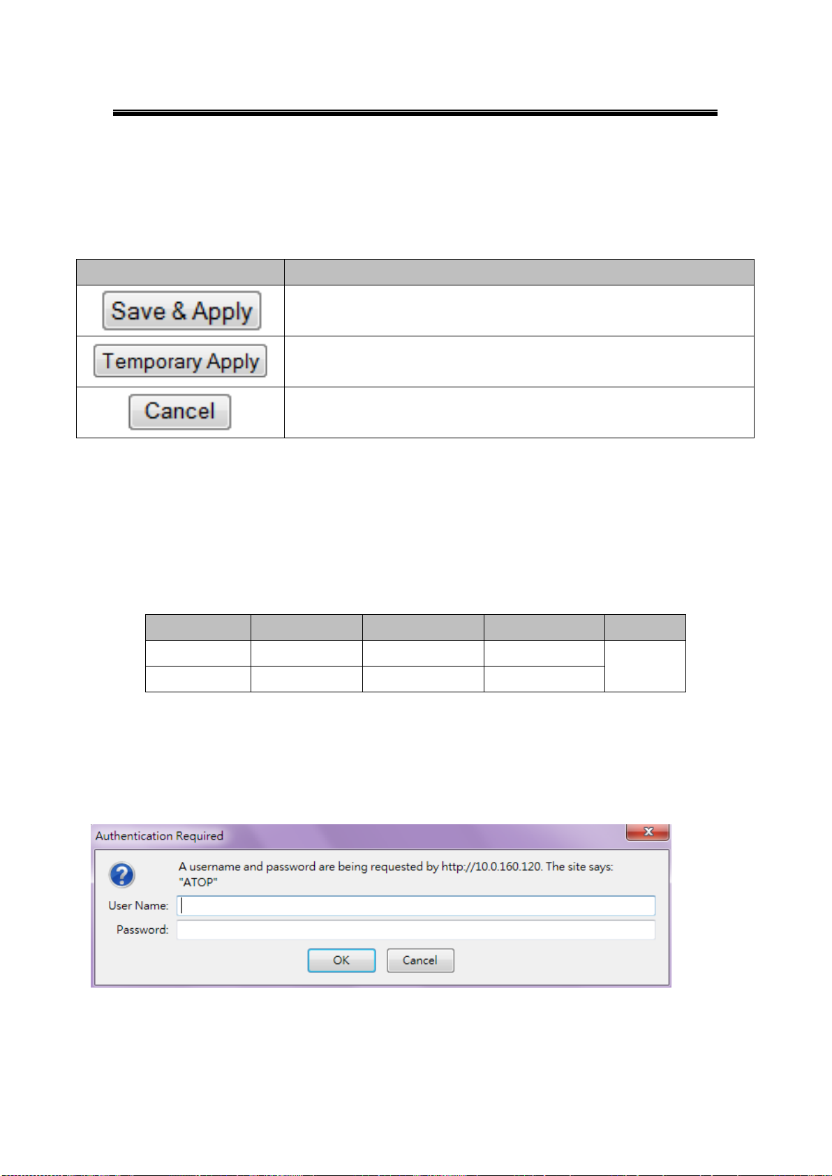
Button
Function
Saves and apply the current configuration input on the page.
As the caption implies, it applies the current configuration until the device
is restarted.
Cancel the current configuration input and shows the original setting.
Interface
Device IP
Subnet mask
Gateway IP
DNS1
LAN
10.0.50.100
255.255.0.0
10.0.0.254
168.95.1.1
WLAN
192.168.1.1
255.255.255.0
192.168.1.254
It is also worth noting that as a first step to view your device’s overall settings, you should use
Serial Manager© (the utility provided in the CD). There will be however, three buttons which
will be present during almost each section, Table 2. 2.
Table 2. 2
2.6 Factory Default Settings
Upon arrival, the device will be set as follows, note that the SW550X Series comes with two
different IP address for LAN and WLAN, Table 2. 3.
Table 2. 3
Once the device is connected to the network, you can use your browser to configure the
device. An authentication request will appear as in Fig. 2. 10.
Fig. 2. 10
14
Page 21

Atop Industrial Wireless Serial Device Server Series
SW550X
User Manual V 1.1
Parameter
Default Values
Security
User Name
admin
Password
Null (blank)
Serial
COM1
RS-232 (RS-422 for Sis models), 9600 bps, 8 data bits, None Parity
bit, 1 stop bit, None Flow Control
Packet Delimiter timer: Auto
COM2
SNMP
SysName of SNMP
0060E9XXXXXX
SysLocation of SNMP
location
SysContact of SNMP
contact
SNMP
Disabled
Read Community
public
Write Community
private
SNMP Trap Server
0.0.0.0
Other relevant default settings are as in Table 2. 4.
Table 2. 4
15
Page 22
Atop Industrial Wireless Serial Device Server Series
SW550X
User Manual V 1.1
3 Configuration
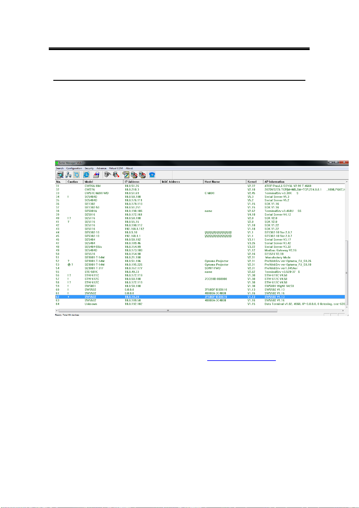
3.1 Administrator Login
As soon as the device is connected on the web, the user can proceed to navigate through its
configuration using Serial Manager© , (utility that comes in the CD); as noted in Fig. 3. 1 below,
important information such as the IP, MAC address, etc is going to be displayed.
Fig. 3. 1
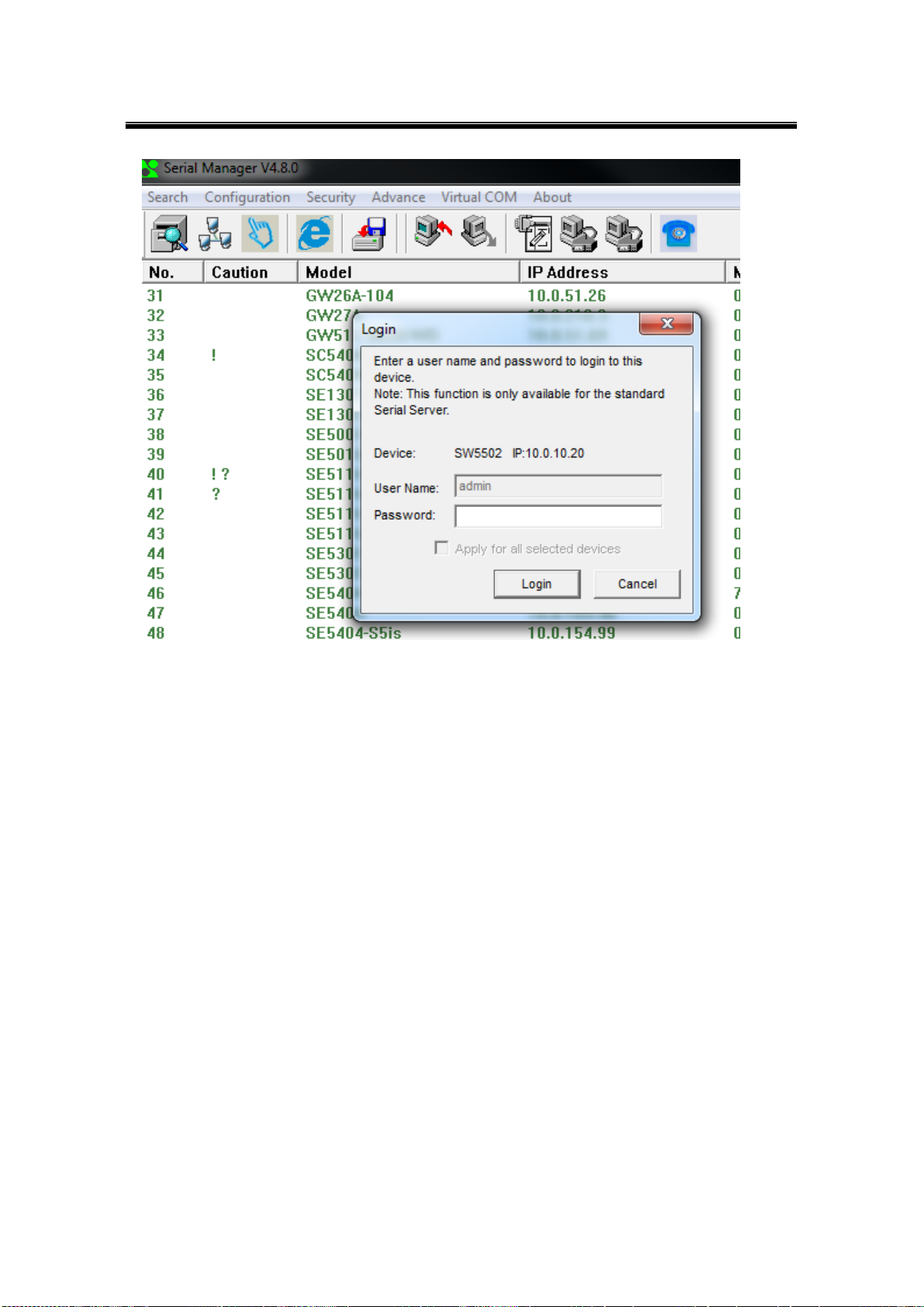
If the name of your device is selected and then double-clicked, a window will pop-out that will
prompt you to enter username and password (see Factory Default Settings for more
information), proceed then to click “Login”, Fig. 3. 2.
16
Page 23
Atop Industrial Wireless Serial Device Server Series
SW550X
User Manual V 1.1
Fig. 3. 2
The device can then be accessed through the utility’s interface; another way of doing this is by
selecting the device and then choosing the “Config by browser” option.
17
Page 24
Atop Industrial Wireless Serial Device Server Series
SW550X
User Manual V 1.1
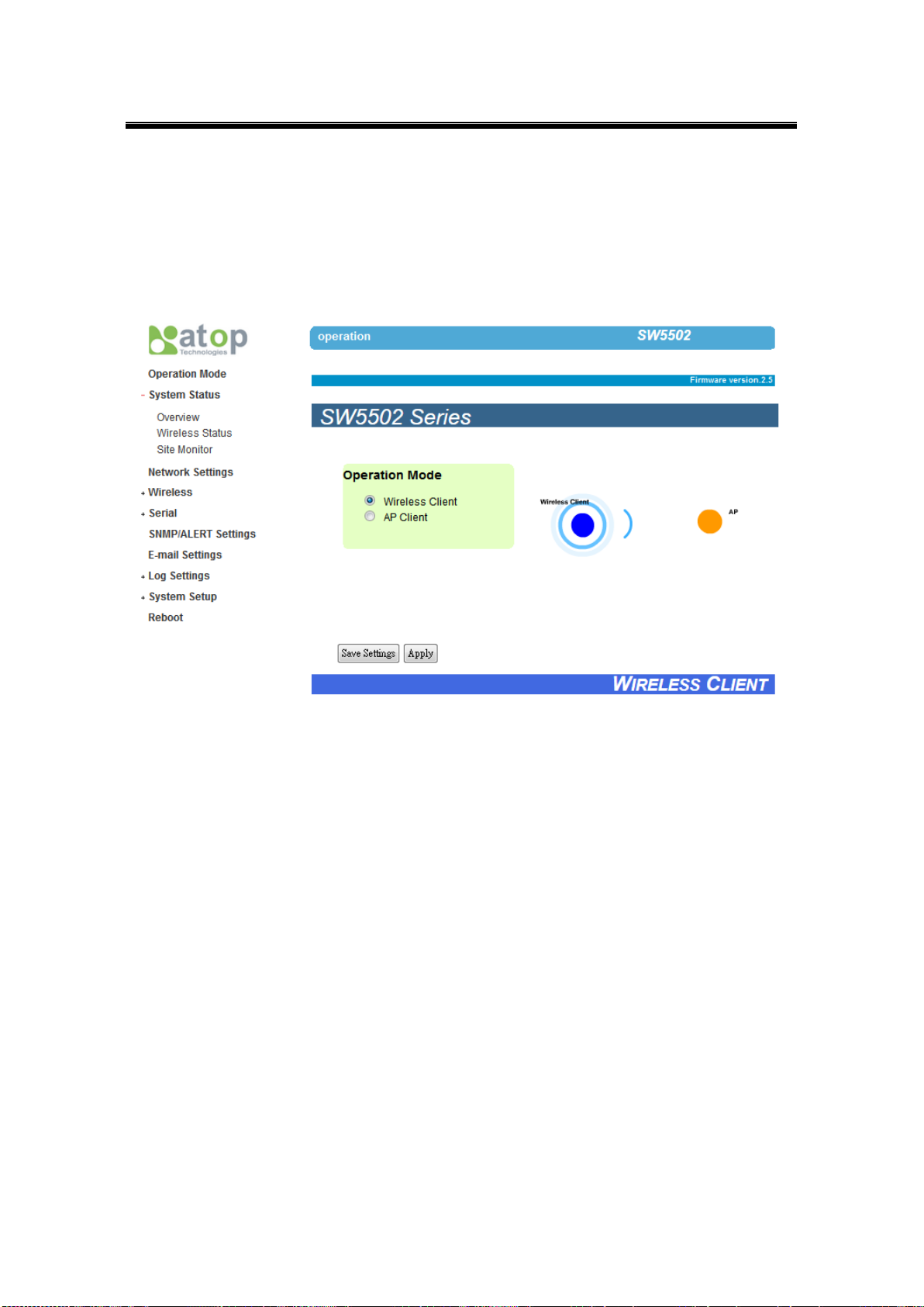
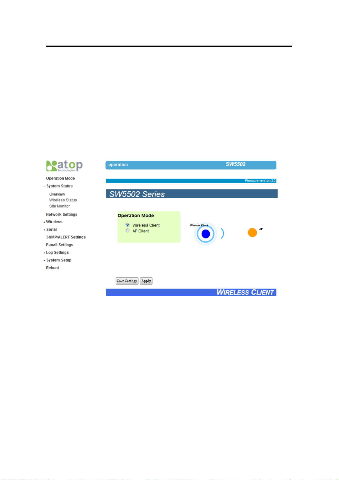
3.2 Operation Mode
This is the welcome screen for the SW550X Series. There are two operation modes to choose
from: Wireless Client and AP Client. In Wireless Client mode, SW550X will have two
independent network interfaces, LAN and WLAN. Each interface would have its own IP
address; hence traffics from the LAN interface would not be bypassed to the WLAN interface,
and vice versa. In the AP Client mode, the LAN and WLAN interfaces would bridge together
to create one single Bridge interface using one IP address. Traffic from either side of the
network would be passed onto the other side of the network.
18
Page 25
Atop Industrial Wireless Serial Device Server Series
SW550X
User Manual V 1.1
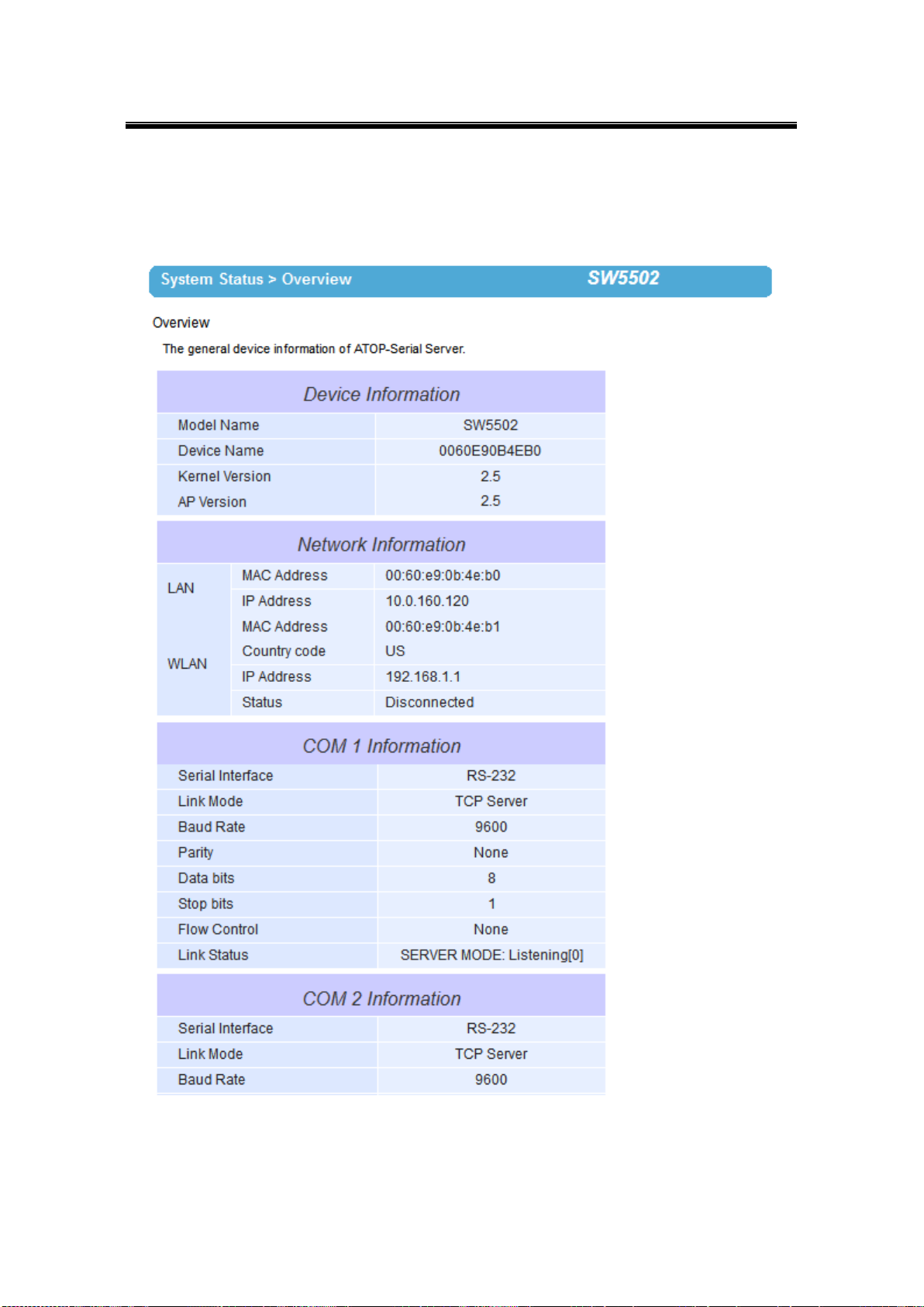
3.3 Overview
Here you will find overall as well as general information.
Fig. 3. 3
19
Page 26
Atop Industrial Wireless Serial Device Server Series
SW550X
User Manual V 1.1
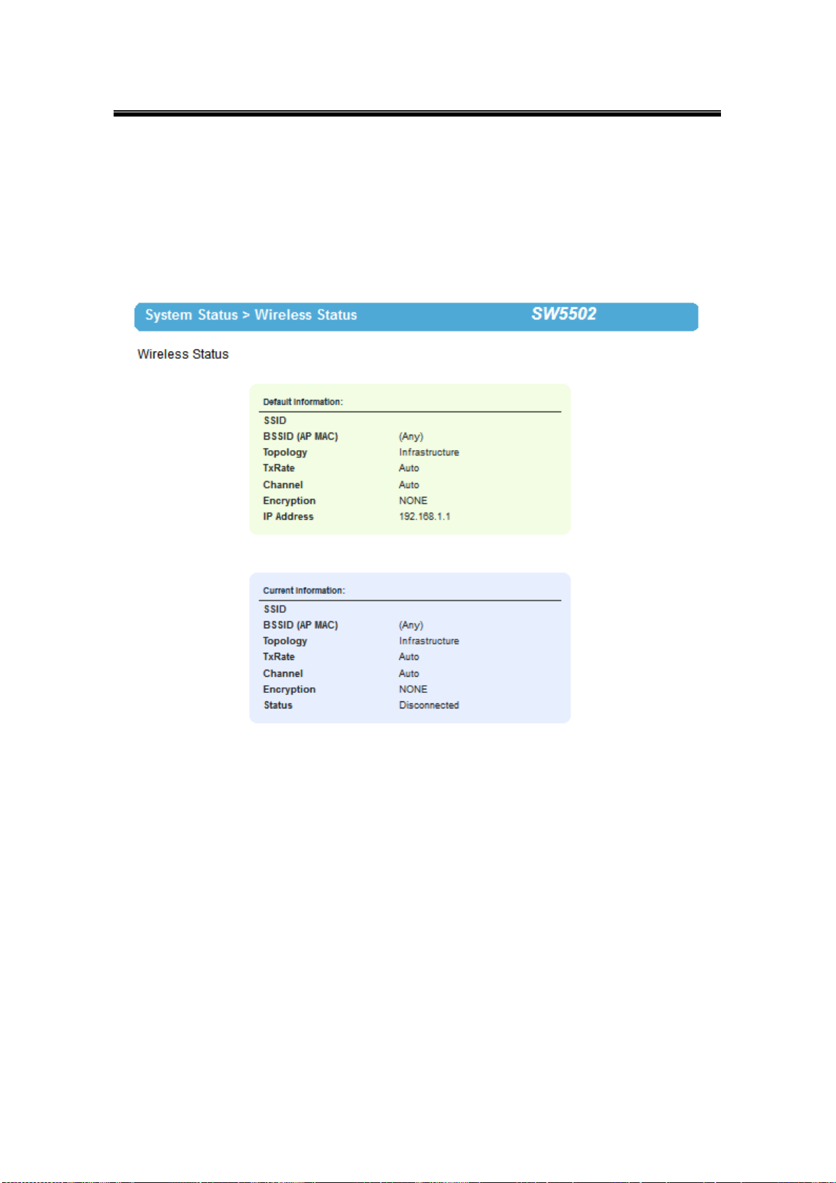
3.3.1 Wireless Status
Wireless Network values will be displayed in this section, the default and current information
can be compared side by side. Please remember to always keep a copy of your own preferred
settings.
Fig. 3. 4
20
Page 27

Atop Industrial Wireless Serial Device Server Series
SW550X
User Manual V 1.1
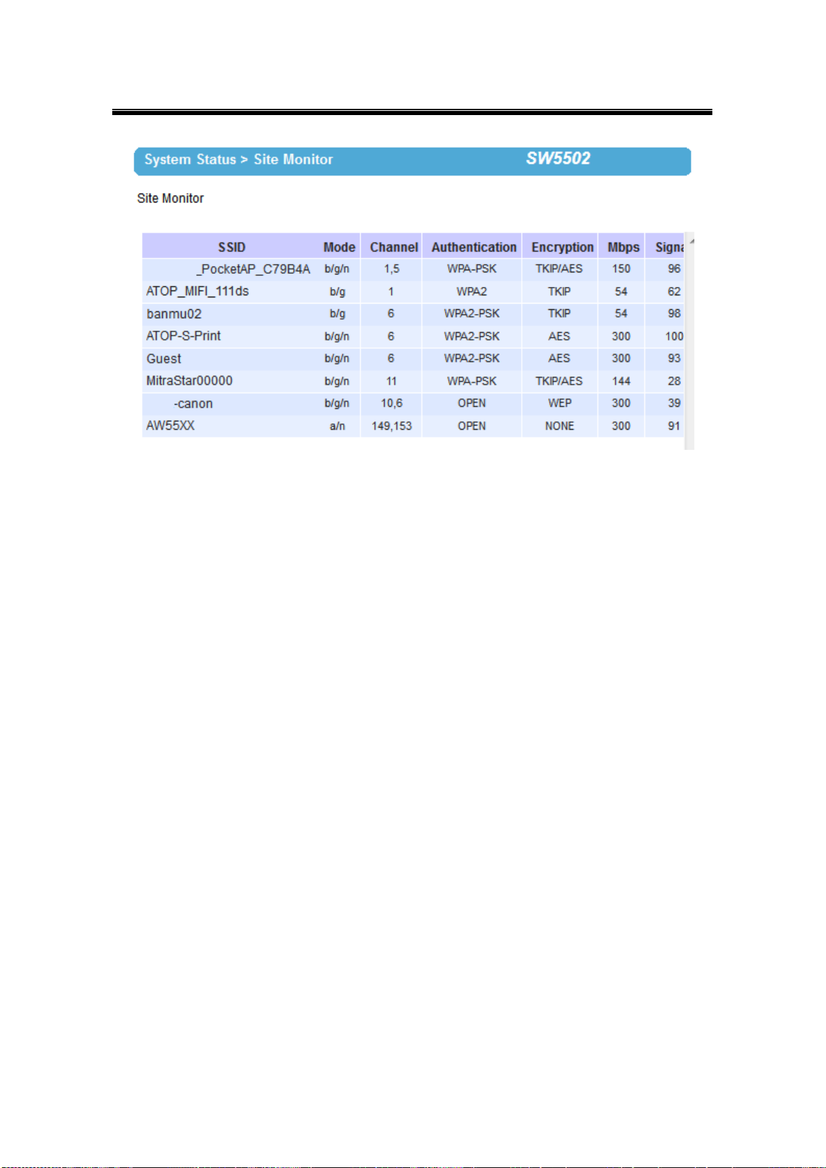
3.3.2 Site Monitor
Site Monitor allows users to view other wireless networks in the neighborhood, it also
provides information on other access points such as SSID, Channel used, the RSSI (Received
Signal Strength Indicator), Security and other parameters used by other access points. It can
be helpful when setting SSID and Channel for this device to avoid SSID name and Channel
conflict and prevent unexpected errors or degraded performance.
Bear in mind that it will take some time (approximately 10 seconds) for this option to gather
information of the surrounding wireless networks, Fig. 3. 5.
Fig. 3. 5
21
Page 28
Atop Industrial Wireless Serial Device Server Series
SW550X
User Manual V 1.1
Fig. 3. 6
22
Page 29

Atop Industrial Wireless Serial Device Server Series
SW550X
User Manual V 1.1
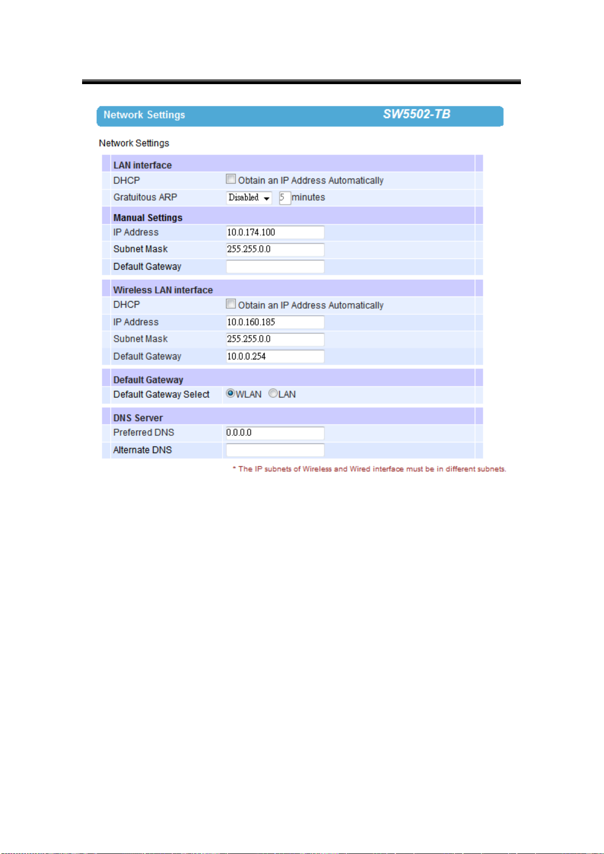
3.4 Network Settings
The SW550X series has the ability for dual connections, i.e., WLAN and LAN at the same time.
It can also get IP information automatically from a DHCP server as well, just check “Obtain an
IP Address Automatically” for it; or enter the values manually if known.
Gratuitous ARP – Enable to periodically send out an ARP response automatically to
announce that SW550X is in the network. The frequency in minutes could be set in the nearby
box.
Note that under the Wireless Client mode, you will see two separate interfaces, LAN and
WLAN. You need to configure them separately into different subnets and choose the interface
that should be the Default Gateway (Fig. 3. 7).
23
Page 30
Atop Industrial Wireless Serial Device Server Series
SW550X
User Manual V 1.1
Fig. 3. 7
Default Gateway Selection specifies whether you are intending to use wireless or LAN
interface as the default gateway. The selected interface is usually the one that is
connected to a gateway or Internet. Settings from one of them will not be applicable to
the other, i.e., if the WLAN is selected over the LAN then IP, Subnet mask, etc., on the
LAN side will be OFF. You can still however be able to change the values of the one not
in use and save those parameters.
Under the AP Client mode, you will only see one bridged interface and the default gateway
selection is unnecessary (Fig. 3. 8).
24
Page 31

Atop Industrial Wireless Serial Device Server Series
SW550X
User Manual V 1.1
Fig. 3. 8
25
Page 32
Atop Industrial Wireless Serial Device Server Series
SW550X
User Manual V 1.1
3.5 Wireless
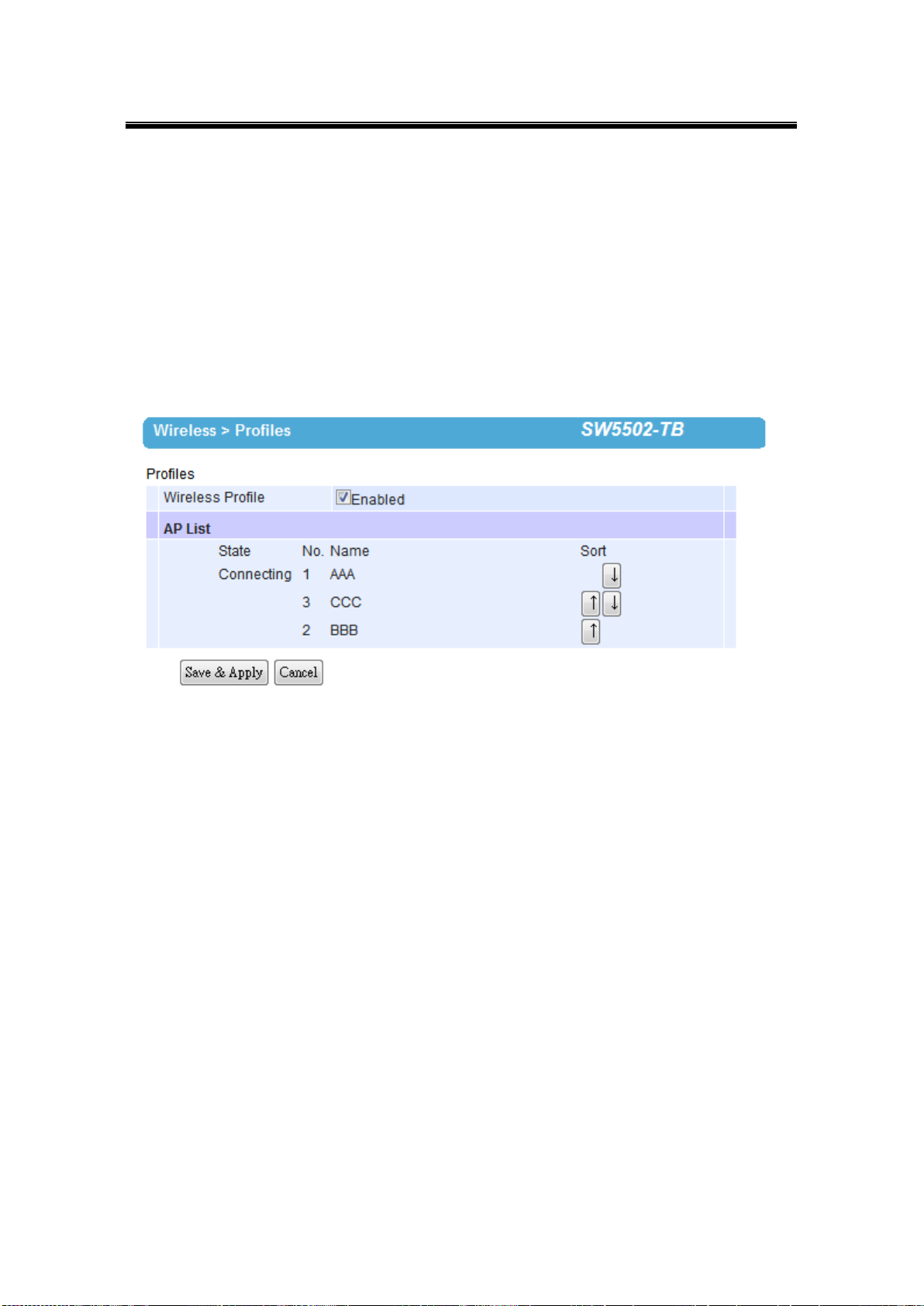
3.5.1 Profiles
You are allowed to save up to ten wireless profiles inside SW550X. SW550X will retry each
and every enabled profile for one minute before continuing to the next profile if the current
profile failed to connect. Use the Sort column to adjust the precedence of the profiles. This
function is disabled by default.
Fig. 3. 9
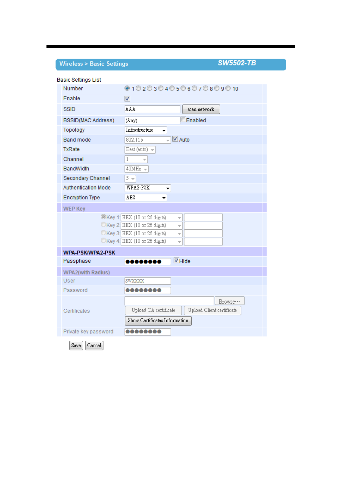
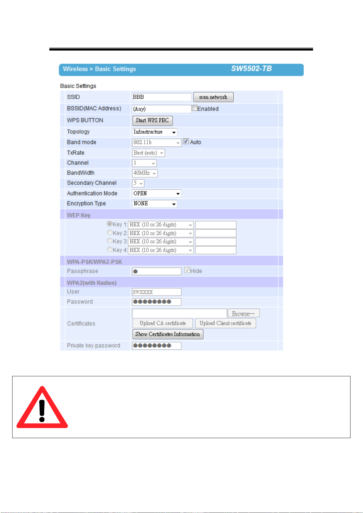
3.5.2 Basic Settings
To set up a wireless network, several parameters are needed as shown in Fig. 3.10
(Wireless Profiles enabled) and Fig. 3. 11 (Wireless Profiles disabled).
26
Page 33
Atop Industrial Wireless Serial Device Server Series
SW550X
User Manual V 1.1
Fig. 3. 10
27
Page 34
Atop Industrial Wireless Serial Device Server Series
SW550X
User Manual V 1.1
Attention
We recommend using LAN interface to setup Wireless Configurations to avoid disconnection
issues. The Web UI might freeze or lock up if the setup is made using the wireless interface
because the connection would be lost whenever wireless settings are changed. It might take some
time for the device to attach to the Access Point with new settings.
Fig. 3. 11
28
Page 35

Atop Industrial Wireless Serial Device Server Series
SW550X
User Manual V 1.1
Caption
Default
SSID
Null
BSSID (MAC Address)
Any (unless enabled)
Topology
Infrastructure
Band Mode
Automatic Detection
Tx Rate (transmission rate)
Best (auto)
Channel
Automatic Detection
Bandwidth1
Automatic Detection
Secondary Channel
Automatic Detection
Authentication Mode
OPEN
Encryption Type
NONE
Caption
Default
Radio Off
Disabled (box not checked)
SSID
Null
BSSID (MAC Address)
Any (unless enabled)
Topology
Ad-Hoc
Band Mode
802.11a
Tx Rate (transmission rate)
Best (auto)
Channel
36
Bandwidth1
20 MHz
Secondary Channel
Disabled
Authentication Mode
OPEN
Encryption Type
NONE
Default Settings in Infrastructure Mode:
Table 3. 1
Default Settings in Adhoc Mode:
Table 3. 2
Number: This row only shows when the Wireless Profile function is enabled. Choose
the profile that you want to configure by selecting its number.
Enable: This row only shows when the Wireless Profile function is enabled. Only the
enabled profiles will show in the Profiles page.
SSID: specifies the SSID (network name) that SW550X should connect to wirelessly.
29
Page 36

Atop Industrial Wireless Serial Device Server Series
SW550X
User Manual V 1.1
There is a “Scan Network” button to the right of the empty box, this button makes it
possible to look for available wireless networks to attach to. Once clicked, it will start
scanning and prompt a window.
BSSID: this refers to the Access Point MAC address on which the SW550X should
connect to. Enabling this option will lock SW550X to that Access Point, so SW550X
would not roam to another Access Point with the same SSID.
WPS BUTTON: the acronym stands for Wi-Fi Protected Setup, PBC stands for Push
Button Configuration. To use this feature, first trigger the WPS process in the Access
Point and click on the WPS PBC button on SW550X’s UI. The AP and the SW550X
should connect automatically. Note that the topology set in this case should be
infrastructure and the Wireless Mode should be Auto so the WPS can work. Note that this
button is unavailable when the Wireless Profiles is enabled.
Topology: Infrastructure (for connecting to an Access Point) or Adhoc (for connecting to
a wireless client). Note that Adhoc mode is unavailable when the Wireless Profiles is
enabled.
Band Mode: 802.11b, 802.11b/g, 802.11b/g/n, 802.11a, and 802.11a/n are available. We
suggest leaving this option to Auto for SW550X to sense the best available mode.
Tx Rate: different rates are available, it is suggested to leave this to Best (auto). This
option is disabled when the band mode is set to Auto.
Channel: the available channels would depend on the band mode and the regulatory
domain selected in the Wireless Advanced Settings. This option is disabled when the
band mode is set to Auto.
Bandwidth: select between 20 MHz or 40 MHz; the latter fills a larger spectrum, hence it
provides a better throughput if it Is allowed by the Access Point. It is not recommended to
use 40 MHz@2.4 GHz (802.11b/g/n).
Secondary Channel: the second channel that SW550X uses when the 40 MHz
bandwidth is enabled.
Authentication Mode: Select between OPEN, WPA-PSK, WPA2-PSK, WPA2 (PEAP),
WPA2(EAP-TLS), and WPA2(EAP-TTLS).
Encryption Type: Select between WEP, TKIP and AES. Please be aware that WEP and
TKIP are not supported by the 802.11n standard, so the wireless link speed would be
limited to 54Mbps.
WEP Key: Enable when Authentication is set to OPEN and Encryption is set to WEP. Up
to 4 different hexadecimal or ASCII keys can be entered in this section.
WPA-PSK/WPA2-PSK Passphrase: Enable when Authentication is set to WPA-PSK or
WPA2-PSK. It can be between 8 and 63 characters long.
30
Page 37

Atop Industrial Wireless Serial Device Server Series
SW550X
User Manual V 1.1
WPA2 (with RADIUS): Depending on the Authentication Mode selected, different fields
would be enabled. WPA2 (PEAP) would require you to provide the user, password, and
the certificates. WPA2 (EAP-TLS) would require you to provide the certificates and
private key password. WPA2 (EAP-TTLS) would require you to provide the user,
password, and the certificates. Please note that only *.pem certificates are supported.
Please remember that 2.4 GHz frequency is easily interfered by other devices that operate in
the same region (namely, Bluetooth, Zigbee, Microwave, etc.) so it is better to choose the
802.11a/n which operates in the 5 GHz when your network allows it.
Steps to Connect to an Access Point
Input the SSID of the connecting Access Point or you can use the “Scan network” to have
SW550X grab the necessary wireless information of surrounding access points in the device’s
coverage area, please be patient as this process might take as long as 10 seconds.
Once it has finished scanning, names and basic properties of available networks will be shown
as in Fig. 3. 12 . After this, you can now select an AP from the list and its settings would load
automatically to the device’s UI.
Fig. 3. 12
31
Page 38

Atop Industrial Wireless Serial Device Server Series
SW550X
User Manual V 1.1
If no wireless networks have been found as shown in Fig. 3. 13.
Fig. 3. 13
32
Page 39
Atop Industrial Wireless Serial Device Server Series
SW550X
User Manual V 1.1
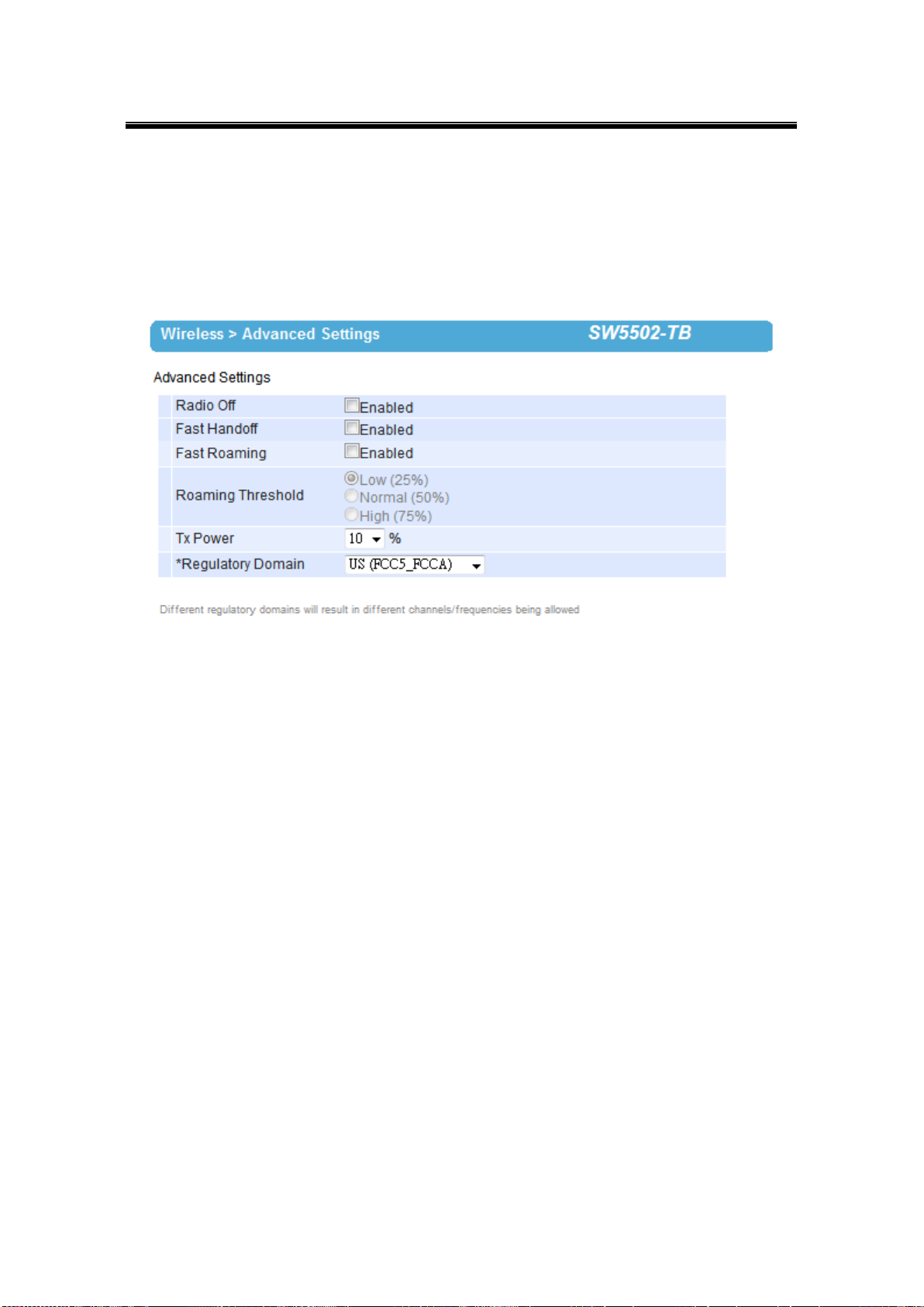
3.7.1 Advanced Settings
Provides details on wireless network parameters for performance tuning. Changes in this
section may affect overall performance, so caution is recommended, if you are not clear of
what you are doing please refrain from altering them, Fig. 3. 14.
Fig. 3. 14
Radio Off – When enabled, this allows the user to turn off the wireless completely.
Fast Handoff – Atop’s proprietary protocol to speed up roaming between AW5500s in
addition to Fast Roaming. Enable to allow AW5500 to share its neighboring AW5500
information to SW550X to further reduce its roaming time.
Fast Roaming – Enable to allow SW550X to scan for available Access Points in the
background to speed up roaming when necessary.
Roaming Threshold – Determine when SW550X should try to connect to another
Access Point when the wireless signal falls below the selected range.
Tx Power – is the SW550X’s Transmission Power; the transmission power can be
reduced to prevent wireless interference to other wireless networks.
STP – The Spanning Tree Protocol is only available in the AP Client mode. Enable this
option if STP is enabled in your network to prevent network loops by setting up the
Forward Delay time. When disabled, SW550X will not forward STP BPDUs.
33
Page 40
Atop Industrial Wireless Serial Device Server Series
SW550X
User Manual V 1.1
3.8 Serial
3.8.1 COM Port Overview
Detail on connectivity protocols and its settings are given in Link Modes and Applications;
this section will only focus on the serial settings.
Fig. 3. 15
34
Page 41

Atop Industrial Wireless Serial Device Server Series
SW550X
User Manual V 1.1
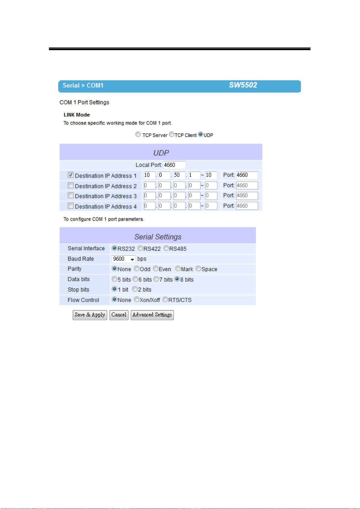
3.8.2 COM Configuration
Fig. 3. 16
Configure serial settings in this page, Fig. 3. 16. Note that these settings need to match the
ones in the serial device.
Serial Interface: Select between RS-232, RS-422, and RS-485. Note that RS-485 refers
to 2-Wire RS-485 and RS-422 is compatible with 4-Wire RS-485.
Baud Rate: Select one of the baudrates from the dropdown box.
Parity / Data Bits / Stop Bits: Configure them accordingly.
Flow Control: Choose between No Flow Control, RTS/CTS (Hardware Flow Control),
and Xon/Xoff (Software Flow Control). If Xon/Xoff is selected, Xon and Xoff characters
are changeable. Defaults are 0x11 for Xon and 0x13 for Xoff. If the connecting program
or serial device would like to receive the Xon/Xoff signals also, enable “Permit Xon/Xoff
Character Pass Through”
35
Page 42

Atop Industrial Wireless Serial Device Server Series
SW550X
User Manual V 1.1
3.8.3 COM Configuration: Advanced Settings
Fig. 3. 17
TCP
TCP Timeout: Specify the value in “TCP Timeout” to force SW550X actively close a TCP
connection after some specific inactivity time (no packets). The default value for it is 3600
seconds. Disabling this option means SW550X would never actively close an established
connection.
Delimiters
Serial to Network Packet Delimiter: Packet delimiter is a way of packing data in the
serial communication. It is designed to keep packets in track. SW550X provides three
types of delimiter: Time Delimiter, Maximum Bytes and Character Delimiter. Note that the
following delimiters (Interval, Max Byte and Character) are programmed in the OR logic.
Meaning that if any of the three conditions were met, SW550X would transmit the serial
data in its buffer over the network.
Interval timeout: SW550X will transmit the serial data in its buffer when the
36
Page 43

Atop Industrial Wireless Serial Device Server Series
SW550X
User Manual V 1.1
Attention
Interval Timeout Manual Calculation
The optimal “Interval timeout” depends on the application, but it must
be at least larger than one character interval within the specified baud
rate. For example, assuming that the serial port is set to 1200 bps, 8
data bits, 1 stop bit, and no parity. In this case, the total number of
bits needed to send a character is 10 bits, and the time required to
transfer one character is (10 (bits)/1200 (bits/s))*1000 (ms/s) = 8.3
ms.
Therefore, you should set the “Interval timeout” to be larger than 8.3
ms. Rounding 8.3 ms to the next integer would get you 9 ms.
specified time interval has reached and no more serial data comes in. The default
value is calculated automatically based on the baud rate. If the automatic value
results in chopped data, the timeout could be increased manually by switching to
“Manual setting” and specifying a larger value.
Max Byte: SW550X will transmit the serial data in its buffer when the specified
length has reached. Enable this option if you would like SW550X to queue the data
until it reaches a specific length. This option is disabled by default.
Character: SW550X will transmit the serial data in its buffer when it sees the
incoming data include the specified character (in HEX format). This field allows one
or two characters. If character delimiter is set to 0x0d, SW550X will push out its
serial buffer when it sees 0x0d (carriage return) in the serial data. This option is
disabled by default.
Network to Serial Packet Delimiter: Same as the delimiters above, but controls data
flow in the opposite direction. It will store data from the network interface in the queue
and send it to over to the serial interface until one of the delimiter conditions is met.
Character Send Interval: This option specifies the time gap between each character.
When set to two second, SW550X would split the data in the queue and only transmit
one character (byte) every two second. This option is disabled by default.
Response Interval Timeout: This option only affects the Request & Response Mode
and has no effect on the Transparent Mode. When TCP data is received (request) and
passed to Serial side, the device will wait for the set time before transferring another TCP
37
Page 44

Atop Industrial Wireless Serial Device Server Series
SW550X
User Manual V 1.1
data if the Serial side did not receive any data (response).
Serial
Serial FIFO: By default, SW550X has its FIFO function enabled to optimize its serial
performance. In some applications (particularly when the flow control is enabled), it may
deem necessary to disable the FIFO function to minimize the amount of data that is
transmitted through the serial interface after a flow off event is triggered to reduce the
possibility of overloading the buffer inside the serial device. Please note that disabling
this option on baud rates higher than 115200bps would reduce the data integrity
noticeably.
Serial Buffer: By default, SW550X will empty its serial buffer when a new TCP
connection is established. This means that the TCP application will not receive buffered
serial data during a TCP link breakage. To keep the serial data when there is no TCP
connection and send out the buffered serial data immediately after a TCP connection is
established, disable this option.
38
Page 45

Atop Industrial Wireless Serial Device Server Series
SW550X
User Manual V 1.1
3.9 SNMP/ALERT Settings
The SNMP is used by network management software to monitor devices in a network to
retrieve network status information and to configure network parameters. The SNMP Settings
shows the configuration of this device so it can be viewed by third-party SNMP software as
shown below, Fig. 3. 18.
Fig. 3. 18
SW550X provides three SNMP fields, which are “System Contact”, usually used to specify
39
Page 46

Atop Industrial Wireless Serial Device Server Series
SW550X
User Manual V 1.1
the device’s contact information in case of emergency; “System Name”, usually used to
identify this device; and “System Location”, usually used to specify the device location.
If you wish to make the device information available for public viewing/editing, Enable the
SNMP function. Fill in the passphrase for the “Read Community”, the group that is allowed to
read the device information and fill in the passphrase for the “Write Community”, the group
that is allowed to read/modify the device information. By default SW550X comes in public for
Read Community and private for Write Community. In case the device raises an alert due to
any unexpected incident, a message will be dispatched to a SNMP trap server. Specify the IP
Address of the SNMP Trap Server designed to collect all alert messages; any changes made
will take effect after the device is restarted.
There are five events that will trigger the alarm; these alerts are useful for security control or
security monitoring:
Cold Start, when there is a power interruption.
Warm Start, when the device resets.
Authentication Failure, when an incorrect username or password is entered.
IP Address Changed, when the device’s IP is changed.
Password Changed, when the administrator password is changed.
Any of the five events would trigger an alert. When enabled, an email alert would be sent to the
designated address in the E-Mail Settings. A Trap alert would be sent to the designated Trap
server in the SNMP Settings.
See E-mail Settings, to specify the email addresses to which the alert message is sent.
40
Page 47

Atop Industrial Wireless Serial Device Server Series
SW550X
User Manual V 1.1
Attention
It is also important to setup Default Gateway and DNS Servers in the Network
Settings properly, so your SW550X can lookup DNS names and route the mails
to the proper default gateway.
3.10 E-mail Settings
In case the device raises an alert and/or warning message, it will send an email to the
administrator’s mailbox. Email Settings allows you to set up the device to be able to send an
email. To set up the email sending, you need to put a “Sender” email address which will be
the “From” on the email. Then, you fill in “Receiver” email address to which the email is sent.
You can send the email to several recipients using Semicolon (;) to separate each email
address. Next step is to set the Email Server. First, you fill in the IP address of a Mail Server
in your local network. If the Mail Server needs a user authentication, you need to enable
“SMTP server authentication required”, and fill in Username and Password. Please
contact your network administrator for Mail Server IP address and the Username and
Password, Fig. 3. 19. You can click on “Send Test Mail” to verify your mail settings.
Fig. 3. 19
41
Page 48
Atop Industrial Wireless Serial Device Server Series
SW550X
User Manual V 1.1
3.11 Log Settings
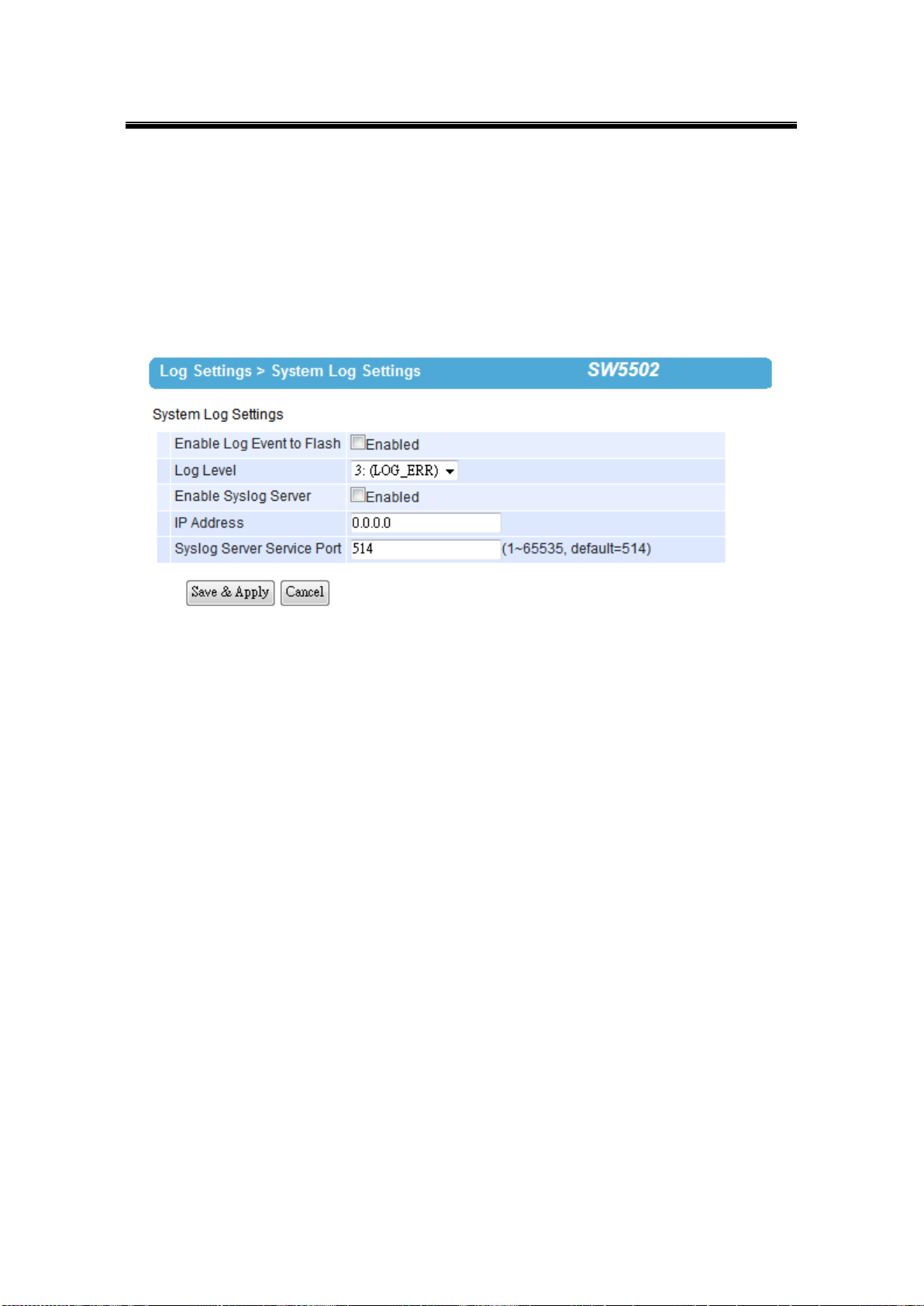
3.11.1 System Log Settings
The Syslog function is turned on by default and cannot be turned off. It is used to log system
events and report to an external Syslog server if necessary.
Fig. 3. 20
Enable Log Event to Flash: this would write log events to the local flash, otherwise the
logs would be cleared when the device restarts because they are stored in the RAM by
default.
Log Level: 3 (we only allow logging at this level).
Enable Syslog Server: enabling this option would allow you to send Syslog events to a
remote Syslog server.
Syslog Server IP: please specify the remote Syslog Server IP.
Syslog Server Service Port: please specify the remote Syslog Server Port.
42
Page 49
Atop Industrial Wireless Serial Device Server Series
SW550X
User Manual V 1.1
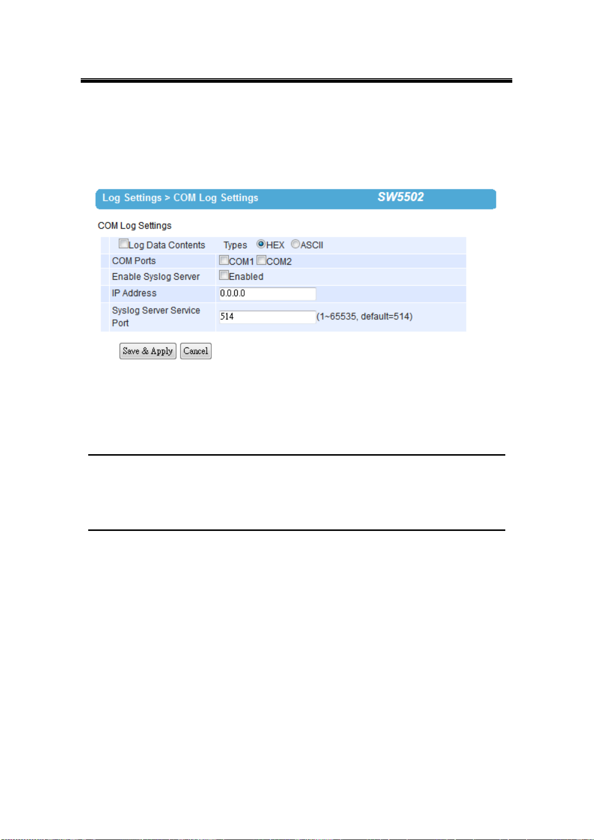
3.11.2 COM Log Settings
Transmitted data could be logged for recording or debugging purposes. The logs could be
reported to an external Syslog server as well.
Fig. 3. 21
Log Data Contents: if enabled, the COM logging function will log the content’s data that
is being transmitted and received (raw bytes). If disabled, COM logging function will only
log data length to reduce system load.
Note: SW550X can store up to 1500 lines internally. A request or a response will consist of one line, data longer than
512 bytes will go into another line. You can retrieve the logs by using a FTP Client, FTP login is the same as the
WebUI. They are located in /var/log/logcomxx (xx is the port number). When the reserved space is full, new logs will
replace old logs. We strongly recommend sending COM logs to a remote Syslog server.
Data types: select the logged data’s format (HEX or ASCII).
COMx: Select the ports to log.
Enable Syslog Server: enabling this option would allow you to send COM logs to a
remote Syslog server. You can send COM logs to the same Syslog server used
previously for event logging.
Syslog Server IP: please specify the remote Syslog server IP.
Syslog Server Service Port: please specify the remote Syslog server Port.
43
Page 50
Atop Industrial Wireless Serial Device Server Series
SW550X
User Manual V 1.1
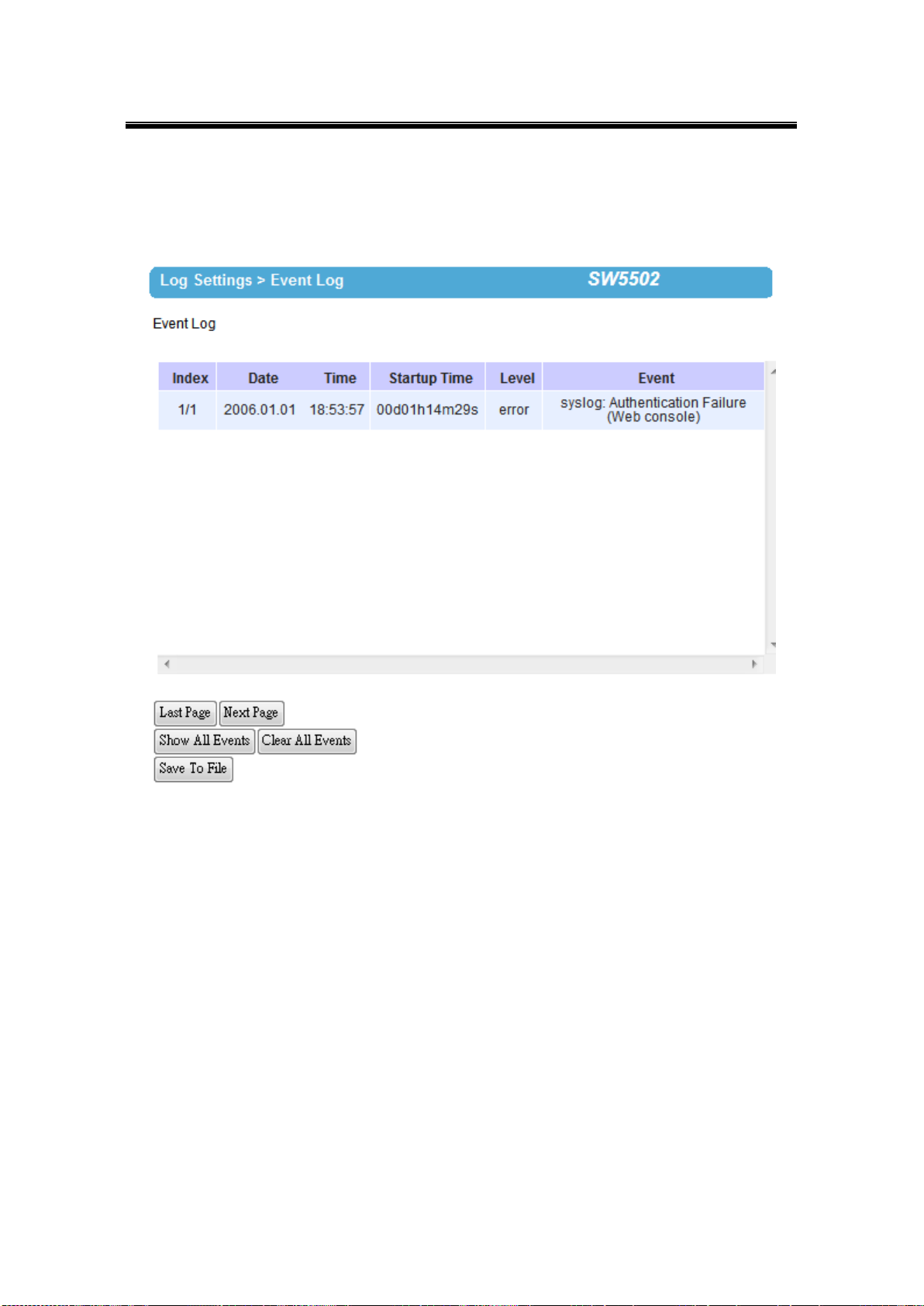
3.11.3 Event Log
Display the current event log stored in the device.
Fig. 3. 22
Click on “Last Page” to go to the last page. Click on “Show All Events” to show all events in
one page. Click on “Clear All Events” to clear the events stored in the device. Click on “Save
To File” to save all the events to a file locally.
44
Page 51
Atop Industrial Wireless Serial Device Server Series
SW550X
User Manual V 1.1
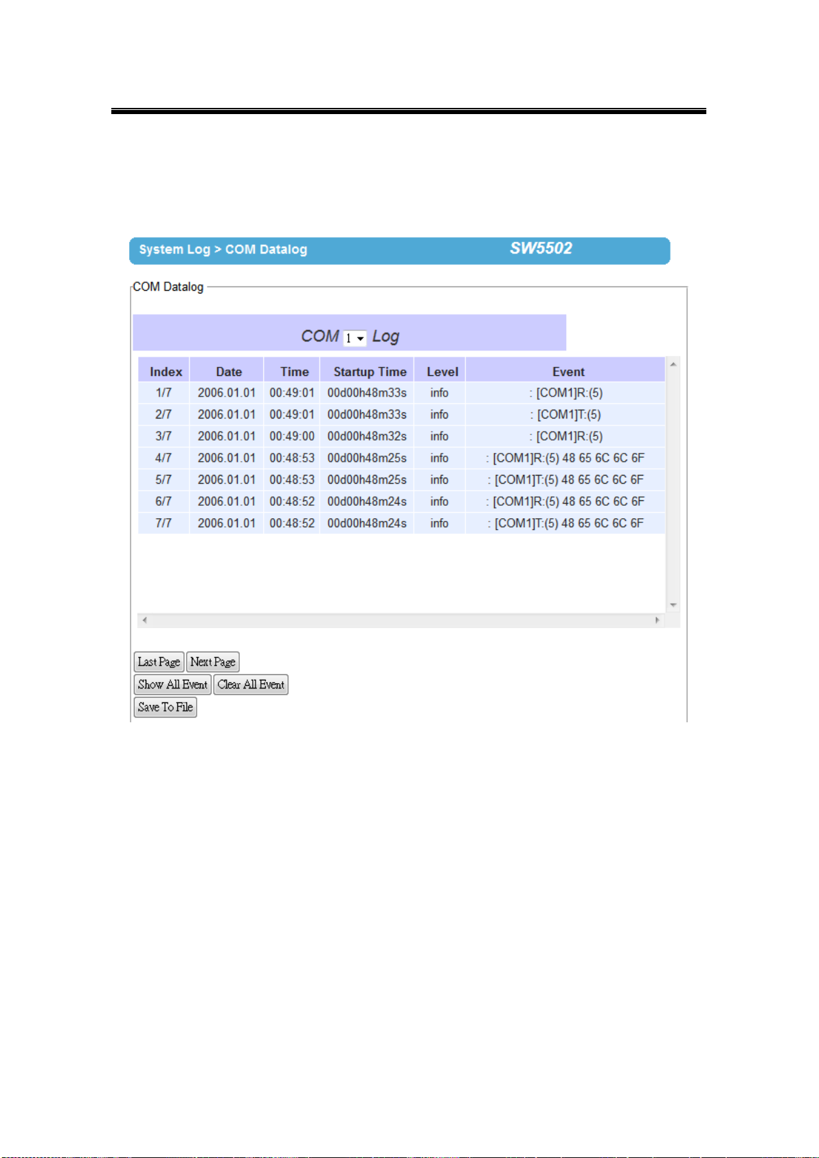
3.11.4 COM Datalog
Display the current COM log stored in the device.
Fig. 3. 23
You can select from the COMx dropdown box to display logs from different COM ports. The
first three lines were set to log data length and the last four lines were set to log data content.
Click on “Last Page” to go to the last page. Click on “Show All Events” to show all events in
one page. Click on “Clear All Events” to clear the events stored in the device. Click on “Save
To File” to save all the events to a file locally.
45
Page 52
Atop Industrial Wireless Serial Device Server Series
SW550X
User Manual V 1.1
Attention
It is also important to setup Default Gateway and DNS Servers in the Network
Settings properly, so your SW550X can lookup DNS names and route the mails to
the proper default gateway.
3.12 System Setup
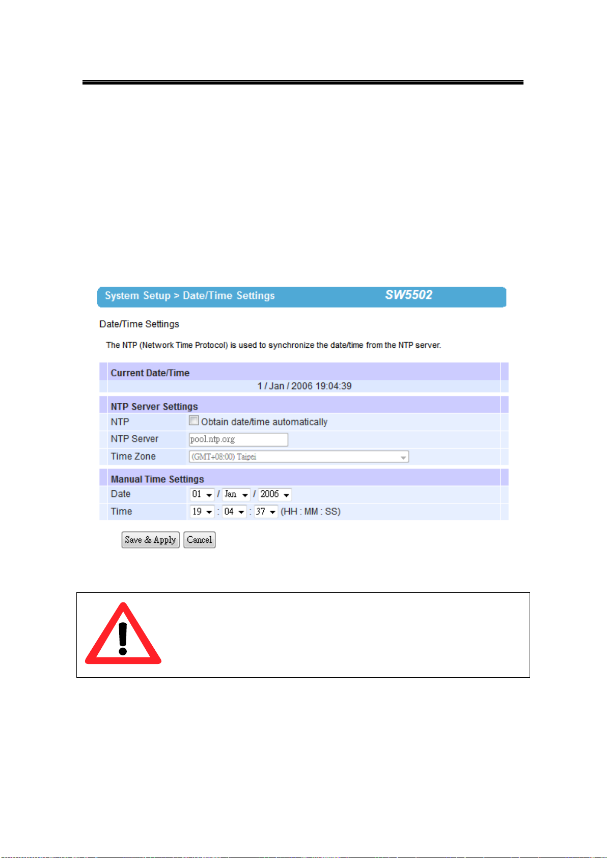
3.12.1 Date/Time Settings
Date and time can be set manually, or using Network Time Protocol (NTP) to automatically
synchronizes with a Time Server. For auto-synching check the box below NTP Server
Settings “Obtain date/time automatically” proceeding then to fill the IP address or host
name for it. If a hostname is entered, the DNS server must be configured properly; a Time
Zone can be selected as well, Fig. 3. 24.
Fig. 3. 24
46
Page 53
Atop Industrial Wireless Serial Device Server Series
SW550X
User Manual V 1.1
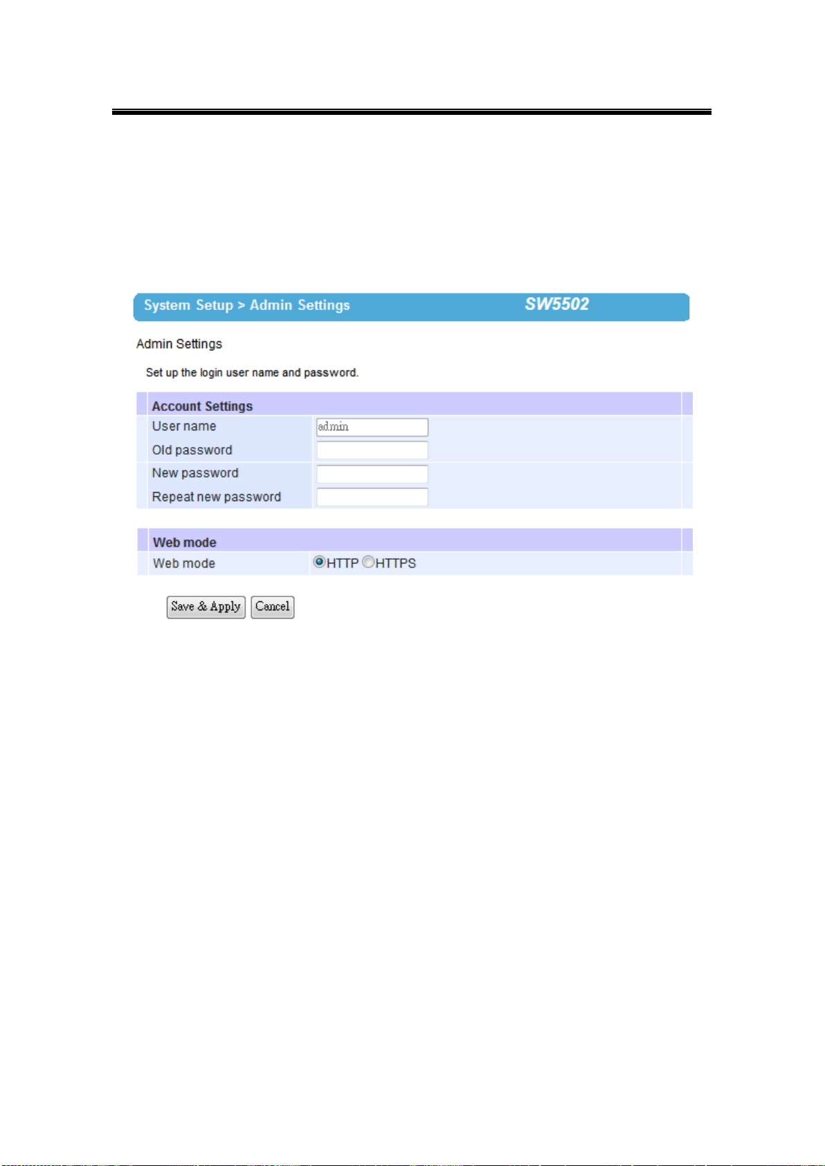
3.12.2 Admin Settings
The SW550X Series allows User and password management, the user’s default is as “admin”
and the password will be in blank as default; to set/change their value just follow the steps
filling in the corresponding blanks and choose Save & Apply in the end, Fig. 3. 25.
Fig. 3. 25
There are two ways to access SW550X’s Web UI. The first one being Hypertext Transfer
Protocol (HTTP) and the other is Hypertext Transfer Protocol Secure (HTTPS). For enhanced
security, it is recommended to use the encrypted HTTPS protocol. Note that HTTP uses port
80 while HTTPS uses the 443 port.
47
Page 54
Atop Industrial Wireless Serial Device Server Series
SW550X
User Manual V 1.1
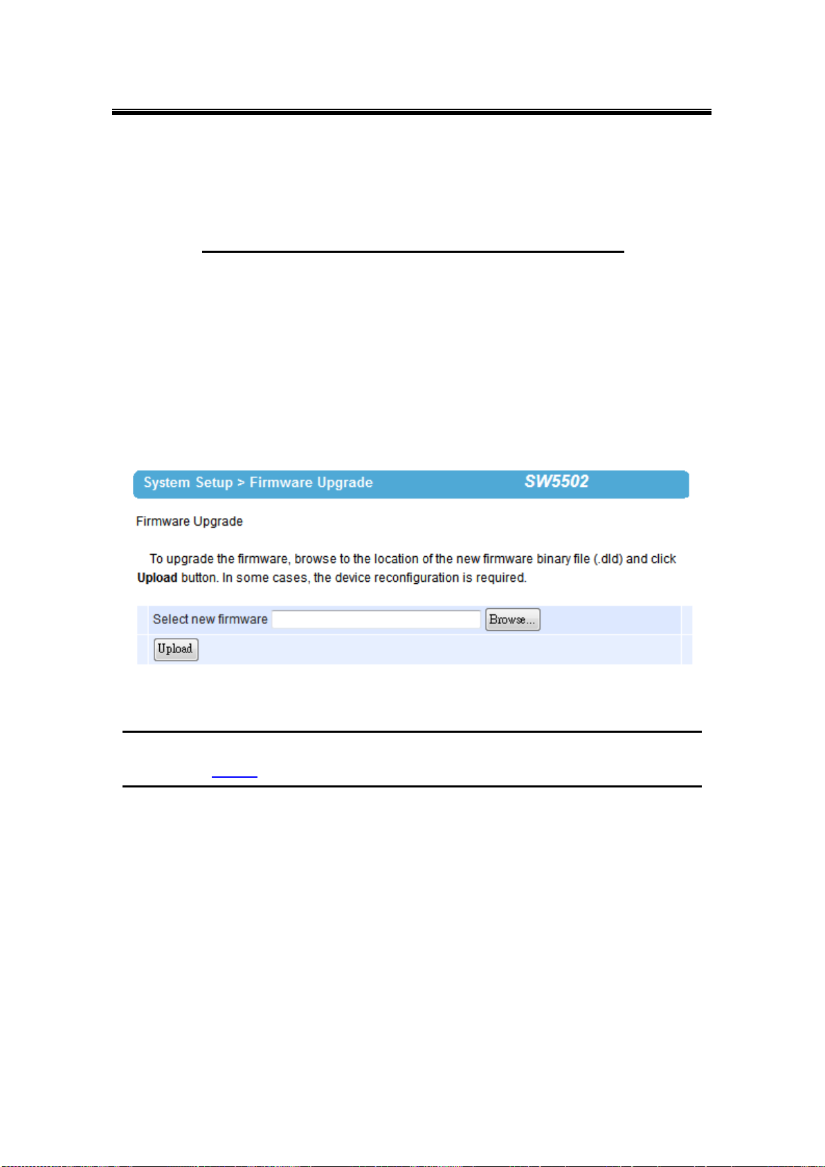
3.12.3 Firmware Upgrade
Updated firmware is provided by our company from time to time (for more information visit our
News & Events webpage), to fix bugs and optimize performance. It is very important that the
device must NOT be turned off or powered off during the firmware upgrading, (please be
patient as this whole process might take up to 7 minutes). Before upgrading the firmware,
please make sure that the device has a reliable power source that will not be powered off or
restarted during the upgrading process. To upgrade a new firmware, once downloaded, copy
the new firmware file to your computer, and then click “Browse” to find the new firmware file
as shown in Fig. 3. 26, then click “Upload”. The program will show the upload status, please
wait until the uploading process is finished (the amount of time varies depending on the
equipment used); the device will then proceed to restart itself.
Fig. 3. 26
Note: if the firmware upgrade process fails and the device becomes unreachable, follow the TFTP Recovery
procedure on the Appendix.
48
Page 55
Atop Industrial Wireless Serial Device Server Series
SW550X
User Manual V 1.1
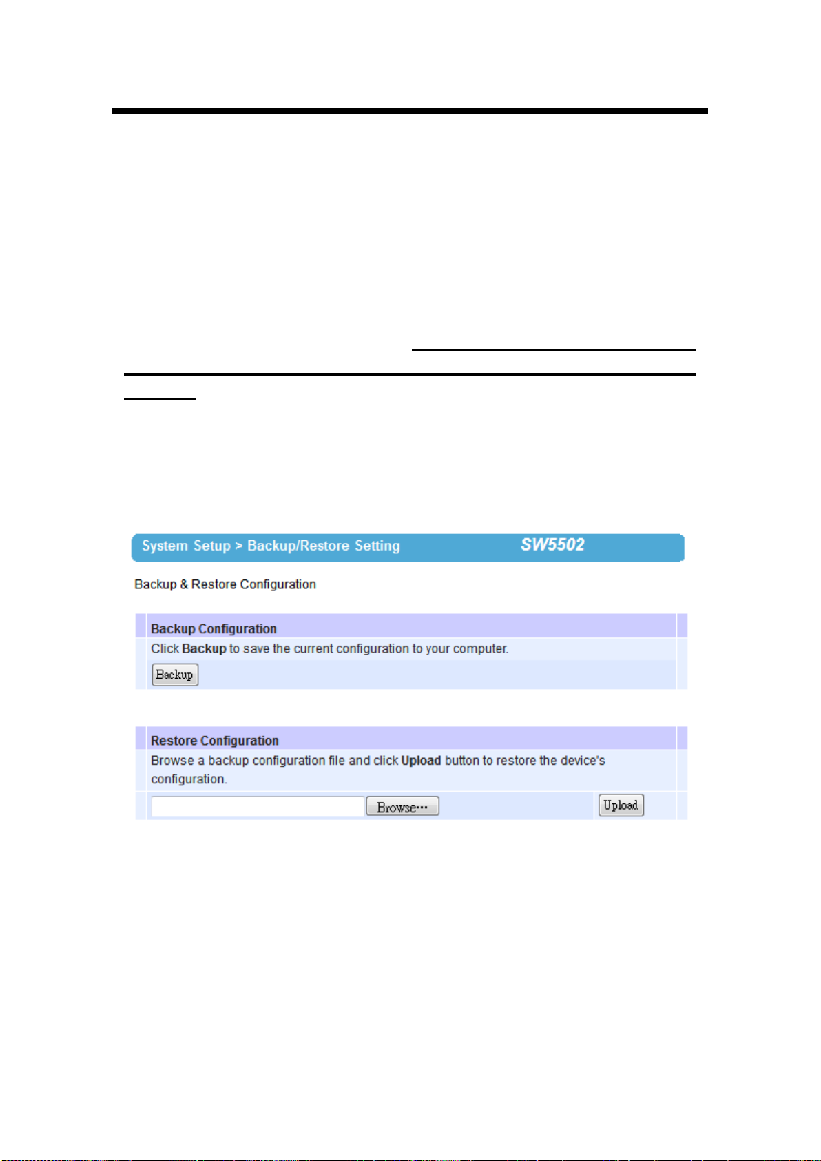
3.12.4 Backup/Restore Setting
Once all the configurations are set and the device is working properly, you may want to back
up your configuration. Backup can be used when the new firmware is uploaded and it is reset
to a factory default settings, it is done to prevent accidental loading of incompatible old settings.
The backup file could also be used to efficiently deploy multiple SW550X Series devices of
similar settings by uploading these settings to the devices.
To backup your configuration, click “Backup”, and a pop-up dialog is prompted for saving the
backup file on your computer. It is important NOT to modify the saved configuration file
by any editor. Any modification to the file may corrupt the file, and it may not be used
for restore. Please contact our authorized distributors for more information on this subject.
To restore the configuration backup, click “Browse” to locate the backup file, and then click
“Upload” to upload the configuration backup file to the device. Once, the backup file is
successfully uploaded; the device will restart, the time needed for this process may vary on the
equipment used, Fig. 3. 27.
Fig. 3. 27
49
Page 56
Atop Industrial Wireless Serial Device Server Series
SW550X
User Manual V 1.1
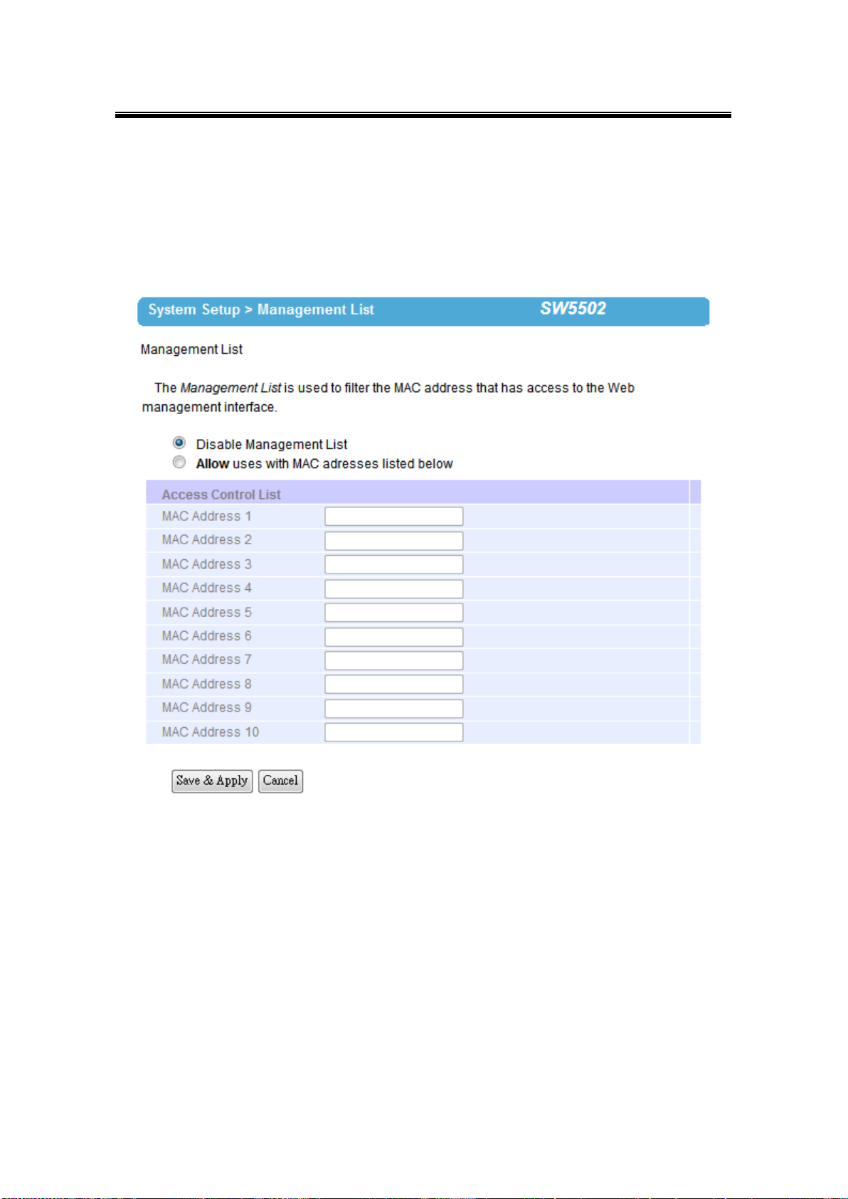
3.12.5 Management List
The Management List is used to filter the MAC address that has access to the Web
management interface. When enabled, only the MAC addresses entered in the Access Control
List below has access to the Web UI.
Fig. 3. 28
50
Page 57
Atop Industrial Wireless Serial Device Server Series
SW550X
User Manual V 1.1
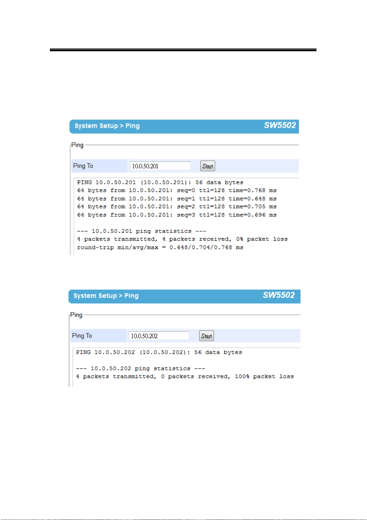
3.12.6 Ping
Use the Ping function to determine whether SW550X can reach the gateway or other devices
in the network or not. This process takes around 20 seconds. Fig. 3. 29 represents a
successful ping while Fig. 3. 30 means that the connecting device is not reachable.
Fig. 3. 31
Fig. 3. 32
51
Page 58

Atop Industrial Wireless Serial Device Server Series
SW550X
User Manual V 1.1
3.13 Reboot and Restore Default Settings
To manually reboot the device, you may click “Reboot”, after the click the device will restart. If
a factory default setting is needed, the “Reset” checking box can be chosen, and then click on
Reboot, Fig. 3. 33.
Fig. 3. 33
52
Page 59

Atop Industrial Wireless Serial Device Server Series
SW550X
User Manual V 1.1
4 Link Modes and Applications
4.1 Link Mode Configuration
SW550X Series supports different Link Modes, which are TCP Server, TCP Client, and UDP.
Under the three Link Modes, TCP Server can support RAW, Virtual COM, or Reverse Telnet
applications. TCP Client can support Virtual COM application. In the upcoming sections, we
will discuss how to setup different Link Modes properly.
Fig. 4. 1
53
Page 60

Atop Industrial Wireless Serial Device Server Series
SW550X
User Manual V 1.1
4.1.1 Link Mode: Configure SW550X as a TCP Server
SW550X Series can be configured as a TCP server in a TCP/IP Network to listen for an
incoming TCP client connection to a serial device. After the connection is established between
the serial device server and the host computer, data can be transmitted in both directions; this
also applies whenever the VCOM is running on server mode. Please be reminded that this is
the device’s default link mode.
Fig. 4. 2
54
Page 61

Atop Industrial Wireless Serial Device Server Series
SW550X
User Manual V 1.1
Fig. 4. 3
SW550X defaults in TCP Server mode, there are additional connection settings that can be
configured, Fig. 4. 3. By selecting the TCP Server mode, a TCP Client program should be
prepared to connect to SW550X.
55
Page 62

Atop Industrial Wireless Serial Device Server Series
SW550X
User Manual V 1.1
Click on the “COM1” link on the left hand side.
Fig. 4. 4
56
Page 63

Atop Industrial Wireless Serial Device Server Series
SW550X
User Manual V 1.1
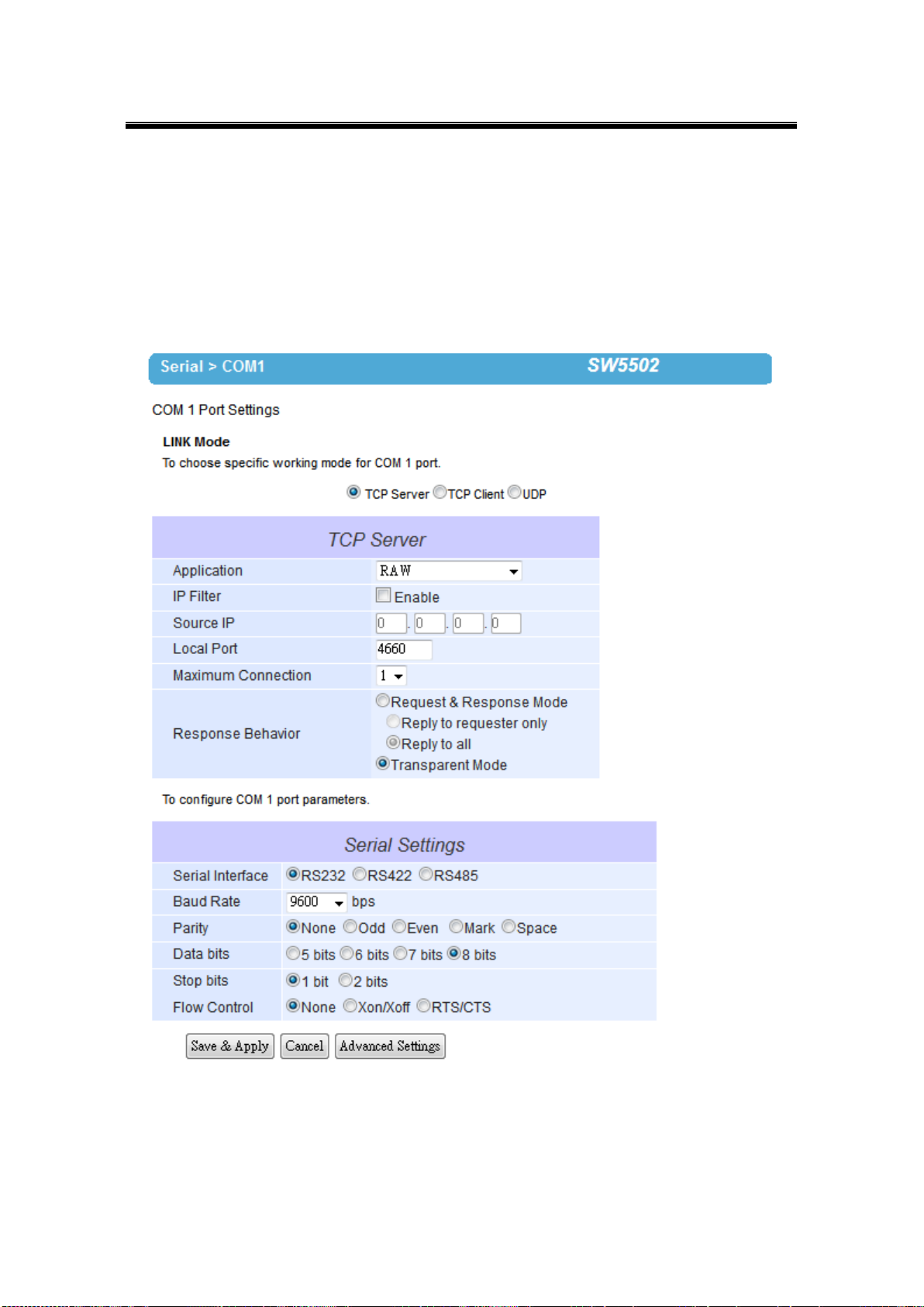
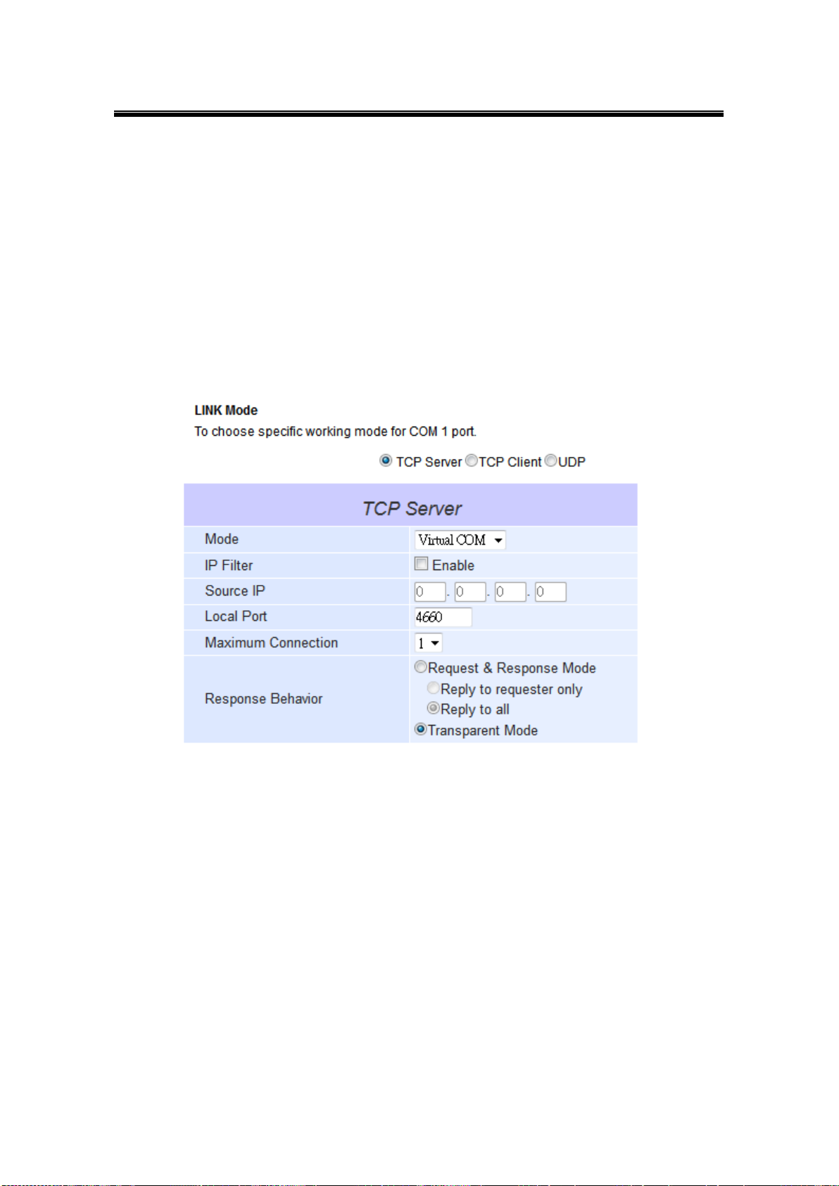
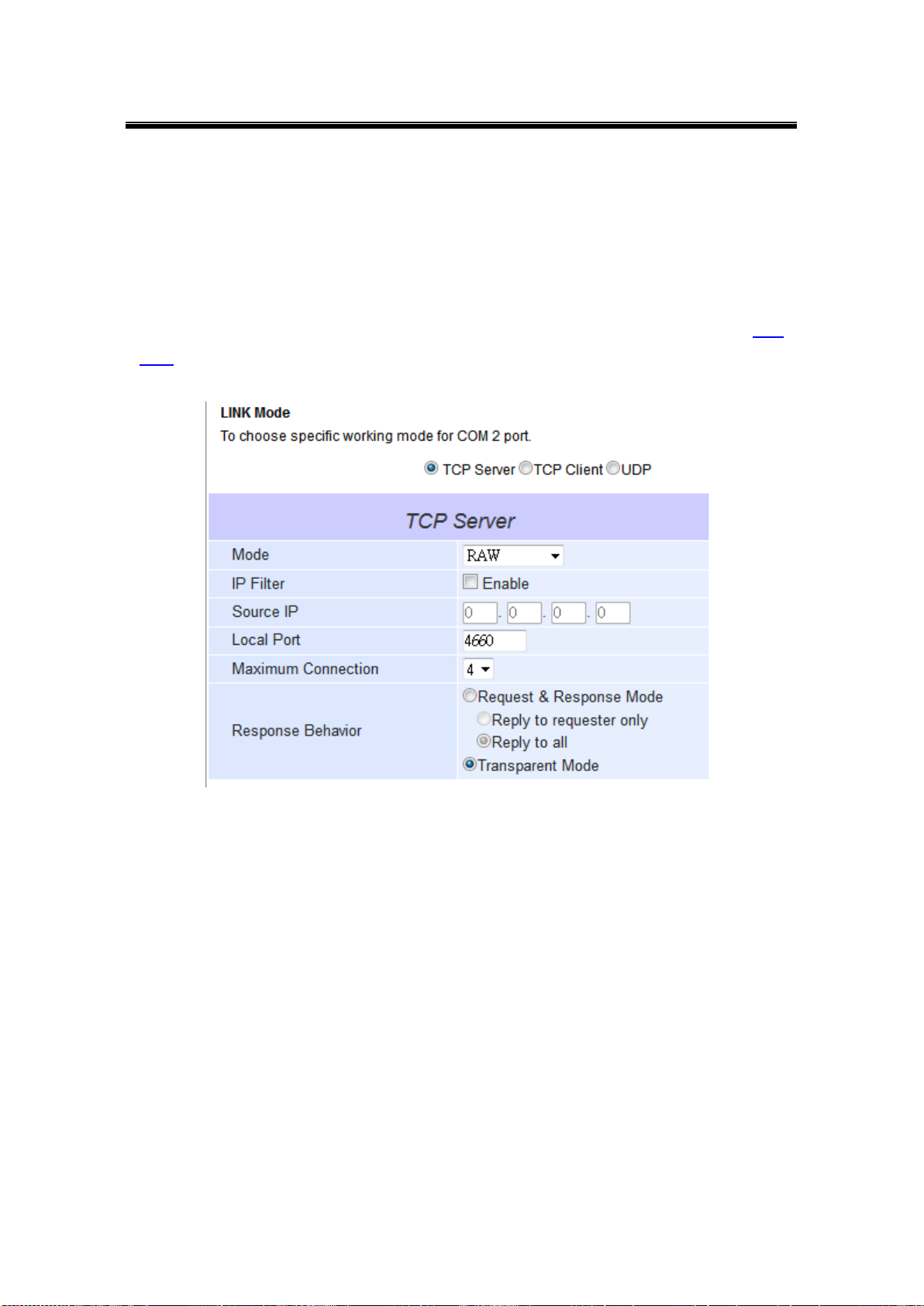
Select TCP Server in the Link Modes; TCP Server is the default link mode. Also in this
section you will find the following options.
Application, there are 3 different communication applications here:
RAW, there is no protocol on this mode, meaning the data is passed
transparently.
Virtual COM, the Virtual COM protocol is enabled on the device to
communicate with a virtualized port from the client. It is possible to create a
Virtual COM port on Windows/Linux in order to communicate with the device
as a Client.
Reverse Telnet, used to connect the device and another serial device
(usually a Terminal Server) with a Telnet program. Telnet programs in
Windows / Linux usually require special handshaking to get the outputs and
formatting show properly. The SW550X series will interact with those special
commands (CR/LF commands) once Reverse Telnet is enabled.
Enter the Local Port, this option specifies the port number that the server should listen
to; it is used by the client to connect to the server. Default local port is 4660.
Go to Response Behavior for more information on this setting. For serial settings, go to
Sec. 3.8.2. For Advanced settings, go to Sec. 3.8.3.
Scroll to the bottom of the page and click on “Save & Apply” button to save the
changes.
Other important variables to consider are:
IP Filter, enables the Source IP option below to block an IP address from accessing the
COM port.
Source IP, specifies the device’s Source IP which will be transmitting data to our Server.
In other words, our Server will only allow data from this IP to flow (hence its own name
implies Source IP); only one source is allowed.
Maximum Connection, the number of devices/clients (max. of 4 clients), to be served is
set in this section.
Response Behavior, in which we will have as options:
Request & Response Mode, it determines how the device will proceed when it
receives requests from connected hosts. Under this mode, the port will hold
requests from all other connected hosts until the serial device replies or the
Response Interval timeout takes into effect to discard it; however, unrequested
data sent from the serial device would be forwarded to all connected hosts.
Reply to requester only, the port will reply to the connected host who
requested the data only.
Reply to all, a reply is sent to all connected hosts.
57
Page 64

Atop Industrial Wireless Serial Device Server Series
SW550X
User Manual V 1.1
Transparent mode, the port will forward requests from all connected hosts to the
serial device immediately and reply to all connected hosts once it receives data
from the serial device.
Note: LINK1 is associated with COM1; LINK2 is associated with COM2, and so on.
58
Page 65

Atop Industrial Wireless Serial Device Server Series
SW550X
User Manual V 1.1
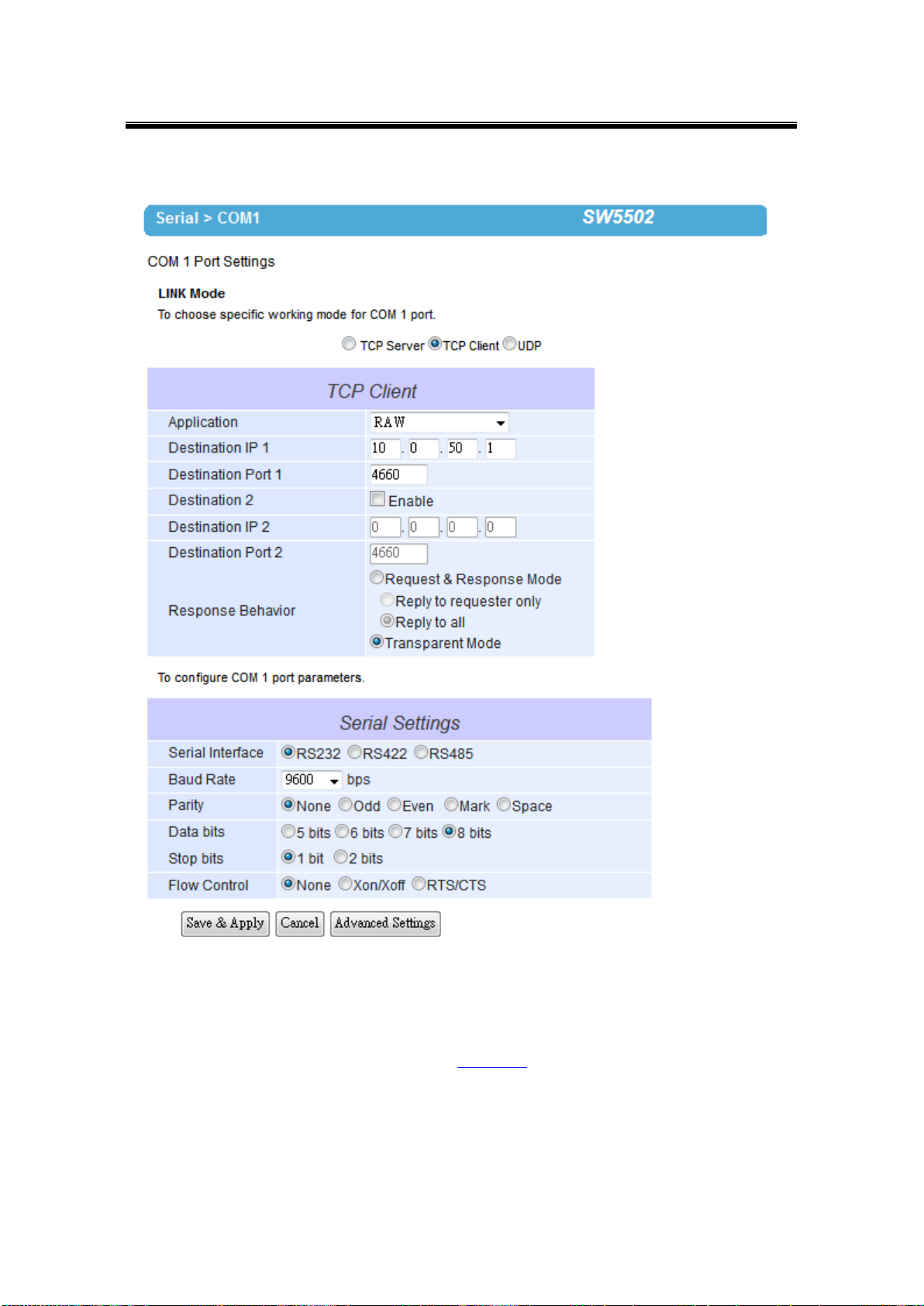
4.1.2 Link Mode: Configure SW550X as a TCP Client
SW550X Series can be configured as a TCP client in TCP/IP Network to establish a
connection with a TCP server in the host computer. After the connection is established, data
can be transmitted between a serial device and a host computer in both directions; this also
applies to Virtual COM running in the client mode.
Fig. 4. 5
59
Page 66

Atop Industrial Wireless Serial Device Server Series
SW550X
User Manual V 1.1
Fig. 4. 6
By selecting the TCP Client mode, it means that a TCP Server program should be prepared to
connect to SW550X. Fig. 4. 6 shows all the settings provided for the TCP Client.
60
Page 67
Atop Industrial Wireless Serial Device Server Series
SW550X
User Manual V 1.1
Click on the “COM1” link on the left hand side.
Fig. 4. 7
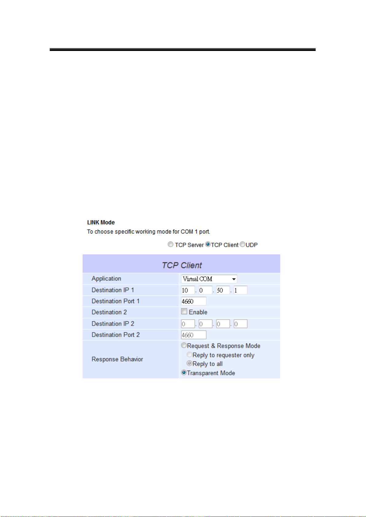
Select TCP Client in the Link modes.
Only two communication modes are available here: RAW and Virtual COM which
definitions are the same as above in Sec. 4.1.1.
Enter the preferred Destination IP and Port. This should match the IP settings of the
TCP Server program.
Enable and enter Destination IP 2 and Port 2 if necessary. Two different servers can
be set here (for redundancy), the second server has to be enabled by ticking the box.
61
Page 68

Atop Industrial Wireless Serial Device Server Series
SW550X
User Manual V 1.1
Go to Response Behavior for more information on this setting. For serial settings, go
to Sec. 3.8.2. For Advanced settings, go to Sec. 3.8.3.
Scroll to the bottom of the page and click on “Save & Apply” button to save the
changes.
62
Page 69
Atop Industrial Wireless Serial Device Server Series
SW550X
User Manual V 1.1
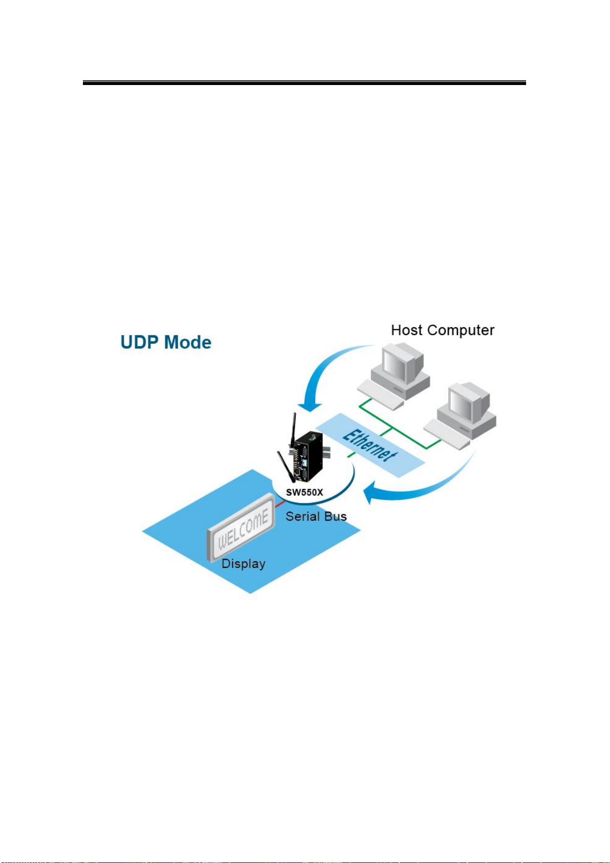
4.1.3 Link Mode: Configure SW550X in UDP
UDP is a faster but connectionless network protocol; it does not guarantee the delivery of
network datagram. The SW550X Series can be configured to transfer data using unicast or
multicast UDP from the serial device to one or multiple host computers, data can be
transmitted between serial device and host computer in both directions.
There is no server or client concept on this protocol, they are called peers or nodes. So here
you only need to specify the Local Port that we should listen to and specify the Destination
IPs of the remote UDP nodes.
Fig. 4. 8
63
Page 70
Atop Industrial Wireless Serial Device Server Series
SW550X
User Manual V 1.1
Fig. 4. 9
SW550X also supports connectionless UDP protocol compared to the connection-oriented
TCP protocol. Please be aware that even though UDP provides better efficiency in terms of
response time and resource usage, it does not guarantee data delivery. It is recommended to
utilize UDP only with cyclic polling protocols where each request is repeated and independent,
such as Modbus Protocol. Fig. 4. 9 shows the UDP settings.
64
Page 71
Atop Industrial Wireless Serial Device Server Series
SW550X
User Manual V 1.1
Click on the “COM1” link on the left hand side.
Fig. 4. 10
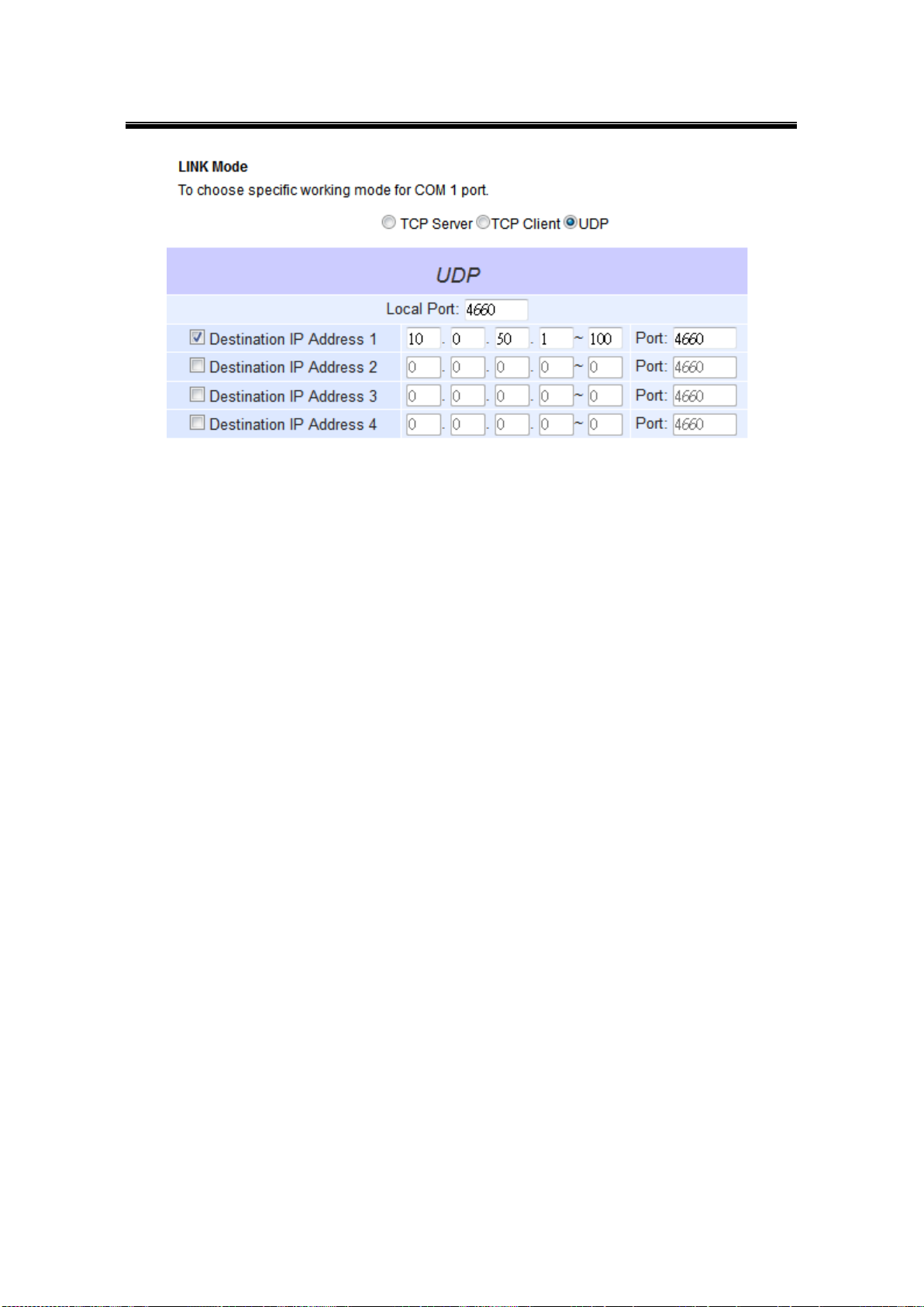
Select UDP in the Link Modes.
Destination IP and Port: Specify the Begin and End IP here. Four groups of range
IPs are allowed. This is the IP address of the UDP program and the Port it is listening
to. Note that the maximum number of UDP nodes that SW550X can handle would
highly depend on the traffic load. We have tested that SW550X can handle up to 200
UDP nodes (baud rate 9600 bps, request interval 100ms, and data length 30bytes).
Enter the Local Listening Port. This is the port that SW550X should listen to. Match
this setting in the UDP program (usually called destination port in the UDP program).
For serial settings, go to Sec. 3.8.2. For Advanced settings, go to Sec. 3.8.3.
Scroll to the bottom of the page and click on “Save & Apply” button to save the
changes.
65
Page 72
Atop Industrial Wireless Serial Device Server Series
SW550X
User Manual V 1.1
4.2 Link Mode Applications
4.2.1 TCP Server Application: Enable Virtual COM
SW550X will encapsulate control packets on top of the real data when Virtual COM is enabled.
This will allow the Virtual COM port in the Windows/Linux system to access SW550X’s COM
ports. The benefit of using Virtual COM is that rewriting an existing COM program to read IP
packets is unnecessary. In other words, it is possible to use an ordinary serial (COM) program.
The conversion/virtualization of IP to COM is all done in the system driver transparently. Fig. 4.
11. shows SW550X in TCP Server mode with Virtual COM enabled.
Fig. 4. 11
Follow Sec. 4.1.1 to configure SW550X in TCP Server mode properly.
Click on the dropdown box of the Application option and switch to “Virtual COM” to
enabled Virtual COM application in SW550X.
Scroll to the bottom of the page and click on “Save & Apply” button to save the
changes.
Configure Virtual COM in the Operating System. For Windows, refer to Chapter 5.
Remember SW550X’s IP address and the Local Port here in order to enter this
information in Serial/IP Virtual COM’s Control Panel later.
66
Page 73
Atop Industrial Wireless Serial Device Server Series
SW550X
User Manual V 1.1
4.2.2 TCP Server Application: Enable RFC 2217
The underlying protocol of Virtual COM is based on RFC 2217, the Telnet COM Control Option.
Therefore, it is possible to use RFC 2217 with SW550X in the TCP Server mode. To do so,
refer to Sec. 4.2.1 to enable Virtual COM, so that SW550X becomes aware of the commands.
Note that there is no need to configure Virtual COM on the Operating System because Virtual
COM ports would not be used.
4.2.3 TCP Client Application: Enable Virtual COM
It is also possible to run VCOM in TCP Client mode, Fig. 4. 12. It is usually easier to use Virtual
COM in the Client mode if SW550X uses dynamic IP (DHCP) because setting a static IP
address in Virtual COM’s Control Panel in the Operating System is not possible.
Fig. 4. 12
Follow Sec. 4.1.2 to configure SW550X in TCP Client mode properly.
Click on the dropdown box of the Application option and switch to “Virtual COM” to
enabled Virtual COM application in SW550X.
Scroll to the bottom of the page and click on “Save & Apply” button to save the
changes.
Configure Virtual COM in the Operating System. For Windows, refer to Chapter 5.
67
Page 74

Atop Industrial Wireless Serial Device Server Series
SW550X
User Manual V 1.1
Remember the Destination Port here in order to enter this information in Serial/IP
Virtual COM’s Control Panel later.
4.2.4 TCP Client Application: Enable RFC 2217
The underlying protocol of Virtual COM is based on RFC 2217, the Telnet COM Control Option.
Therefore, it is possible to use RFC 2217 with SW550X in the TCP Client mode. To do so, refer
to Sec. 4.2.3 to enable Virtual COM, so that SW550X becomes aware of the commands. Note
that there is no need to configure Virtual COM on the Operation System because Virtual COM
ports would not be used.
4.2.5 TCP Server Application: Configure SW550X as a Pair Connection Master
Pair Connection is useful when pairing up two serial devices over the Ethernet or when it is
impossible to install Virtual COM in the serial device. Pair connection does require two
SW550X to work in pair, one would be the Pair Connection Master and the other would be the
Pair Connection Slave.
Fig. 4. 13
Follow Sec. 4.1.1 to configure SW550X in TCP Server mode properly.
Click on the dropdown box of the Application option and switch to “Pair Connection
Master” to enabled Pair Connection application in SW550X.
68
Page 75

Atop Industrial Wireless Serial Device Server Series
SW550X
User Manual V 1.1
Scroll to the bottom of the page and click on “Save & Apply” button to save the
changes.
Remember Pair Connection Master’s IP address here in order to enter this
information in the Slave later.
Proceed to the section below to configure a Slave to connect to this Master.
69
Page 76

Atop Industrial Wireless Serial Device Server Series
SW550X
User Manual V 1.1
4.2.6 TCP Client Application: Configure SW550X as a Pair Connection Slave
A Pair Connection Slave, is shown in Fig. 4. 14; it is necessary to pair up with a Pair
Connection Master. Please setup a Pair Connection Master first before proceeding.
Fig. 4. 14
Follow Sec. 4.1.2 to configure SW550X in TCP Client mode properly.
Click on the dropdown box of the Application option and switch to “Pair Connection
Slave” to enabled Pair Connection application in SW550X.
Match the Destination IP with the settings of Pair Connection Master’s IP that was
setup previously.
Scroll to the bottom of the page and click on “Save & Apply” button to save the
changes.
70
Page 77

Atop Industrial Wireless Serial Device Server Series
SW550X
User Manual V 1.1
4.2.7 TCP Server Application: Enable Reverse Telnet
Reverse Telnet is useful if a telnet program is used to connect to SW550X and the serial
interface of the SW550X is connected to a Terminal Server. Telnet programs in Windows/Linux
require special handshaking to get the outputs and formatting show properly. SW550X will
interact with those special commands (CR/LF commands) if Reverse Telnet is enabled.
Fig. 4. 15
Follow Sec. 4.1.1 to configure SW550X in TCP Server mode properly.
Click on the dropdown box of the Application option and switch to “Reverse Telnet”
to enabled telnet application in SW550X.
Scroll to the bottom of the page and click on “Save & Apply” button to save the
changes.
71
Page 78

Atop Industrial Wireless Serial Device Server Series
SW550X
User Manual V 1.1
IP Address
Link Mode
Local Listening Port
Destination IP
Destination Port
SW5501 Master COM1
10.0.50.100
UDP
5000
10.0.50.200~10.0.50.203
5000
SW5501 Master COM1
10.0.50.100
UDP
5001
10.0.50.200~10.0.50.201
5001
SW5502 Slave 1 COM1
10.0.50.200
UDP
5000
10.0.50.100
5000
SW5502 Slave 1 COM2
10.0.50.200
UDP
5001
10.0.50.100
5001
SW5502 Slave 2 COM1
10.0.50.201
UDP
5000
10.0.50.100
5000
SW5502 Slave 2 COM2
10.0.50.201
UDP
5001
10.0.50.100
5001
SW5501 Slave 3 COM1
10.0.50.202
UDP
5000
10.0.50.100
5000
SW5501 Slave 4 COM1
10.0.50.203
UDP
5000
10.0.50.100
5000
4.2.8 UDP Application: Multi-Point Pair Connection
It is also possible to setup pair connection in UDP mode to have more than one Pair
Connection Master or Slave to communicate to each other. For example, it is possible to setup
one Modbus Master and six Modbus Slaves in UDP, Fig. 4. 16. Note again that UDP does not
guarantee data delivery and only data would be transmitted over Ethernet; other serial pings
are not transmited. If RS-232 along with flow control, it is recommended to use Multi-Point Pair
Connection in TCP, see Sec. 4.2.10.
Note: the destination IP and Port of the Slaves need to be equal to the Master’s IP and Port. Local Listening Port of
the Slaves need to be equal to the Master’s Destination Port, see Table for an example.
Table 4. 1
72
Page 79

Atop Industrial Wireless Serial Device Server Series
SW550X
User Manual V 1.1
Fig. 4. 16
73
Page 80
Atop Industrial Wireless Serial Device Server Series
SW550X
User Manual V 1.1
4.2.9 TCP Server Application: Multiple TCP Connections
The Multi-Connection option will allow up to a maximum of four TCP Client connections. Note
that it is also possible to use this multi-connection feature in conjunction with other TCP Server
applications, such as Virtual COM, Pair Connection, and Reverse Telnet. For example,
enabling multi-connection along with Pair Connection will result in Multi-Point Pair Connection
in TCP mode (Sec. 4.2.10). For more information on Response behavior please go to Sec.
4.1.1.
Fig. 4. 17
74
Page 81

Atop Industrial Wireless Serial Device Server Series
SW550X
User Manual V 1.1
IP Address
Link Mode
Application
Local Listening
Port
Destination
IP
Destination
Port
SW5501 Master COM1
10.0.50.100
TCP Server
Pair Connection Master
4660
-
-
SW5502 Slave 1 COM1
10.0.50.200
TCP Client
Pair Connection Slave
-
10.0.50.100
4660
SW5502 Slave 1 COM2
10.0.50.200
TCP Client
Pair Connection Slave
-
10.0.50.100
4660
SW5501 Slave 2 COM1
10.0.50.201
TCP Client
Pair Connection Slave
-
10.0.50.100
4660
SW5501 Slave 3 COM1
10.0.50.202
TCP Client
Pair Connection Slave
-
10.0.50.100
4660
4.2.10 TCP Server Application: Multi-Point TCP Pair Connections
The difference between Multi-Point TCP Pair Connection and Multi-Point UDP Pair Connection
is that the TCP implementation would also exchange flow control pins for RS-232. However,
the TCP Server is limited to a maximum of four connections. If there are four serial devices and
they don’t use flow control pins with RS-232 or RS-485, it is possible to setup pair connection
in UDP mode, Sec. 4.2.8. After multi-connection is enabled in the WebUI, refer to the following
table to setup Pair Connection as in Fig. 4. 18.
Table 4. 2
Fig. 4. 18
75
Page 82
Atop Industrial Wireless Serial Device Server Series
SW550X
User Manual V 1.1
4.3 Wireless Topology
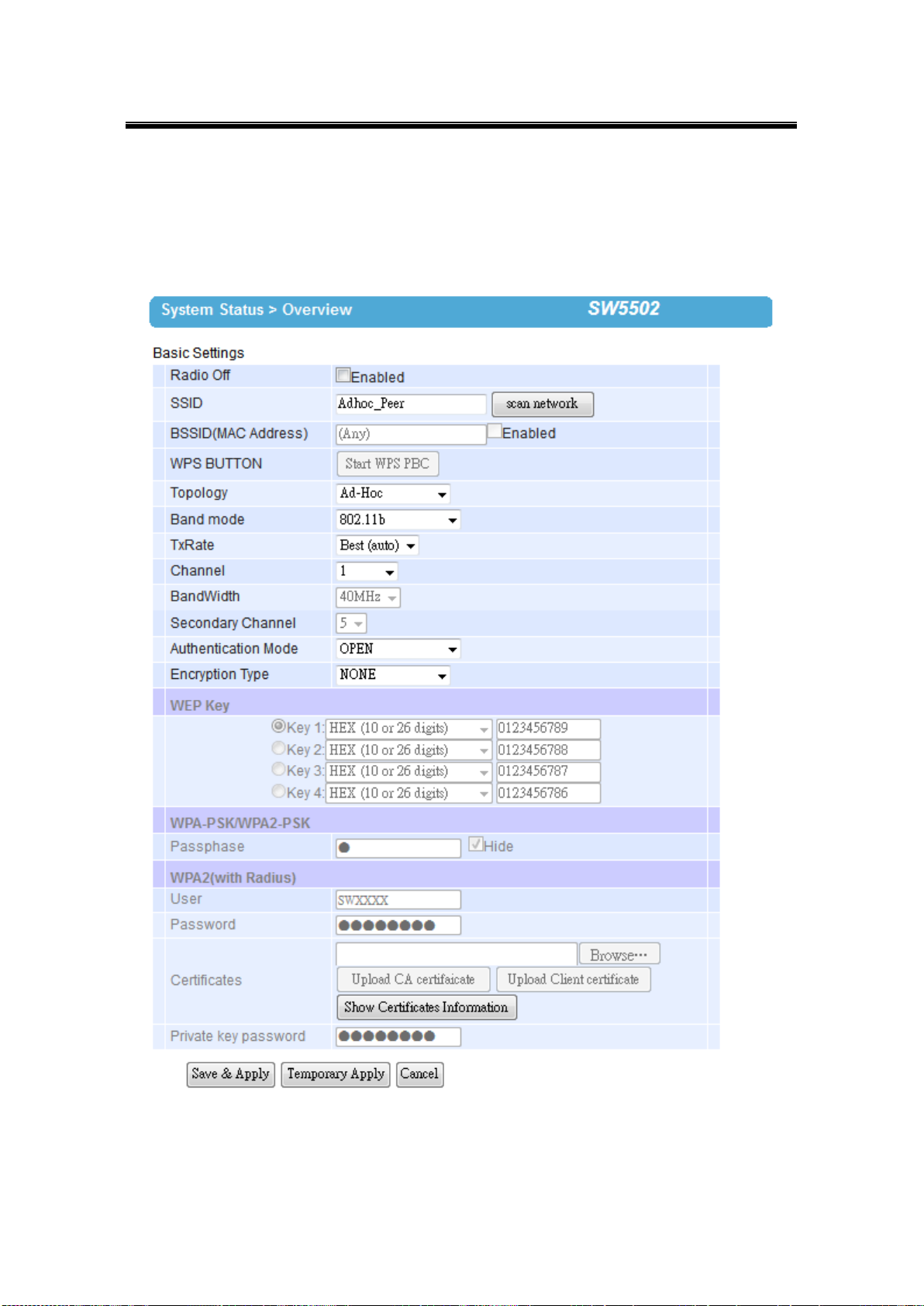
4.3.1 Configure SW550X as a Wireless Ad-Hoc Peer
Fig. 4. 19
76
Page 83

Atop Industrial Wireless Serial Device Server Series
SW550X
User Manual V 1.1
Topology
Adhoc
Band Mode
802.11b (alternatively you could use 802.11a which is less affected by interference), it provides
better wireless sensitivity with lower maximum rate at 11Mbps.
Tx Rate
Auto
Channel
1; we recommend using 1, 6, or 11 (for 2.4 GHz).
Authentication
Open
Encryption
WEP
WEP Key
For 64-bit encryption, enter 5 ASCII value or 13 Hexadecimal digits. For 128-bit encryption, enter
13 ASCII value or 26 Hexadecimal digits. Use 128-bit when possible.
Configure your device as explained below.
Table 4. 3
77
Page 84
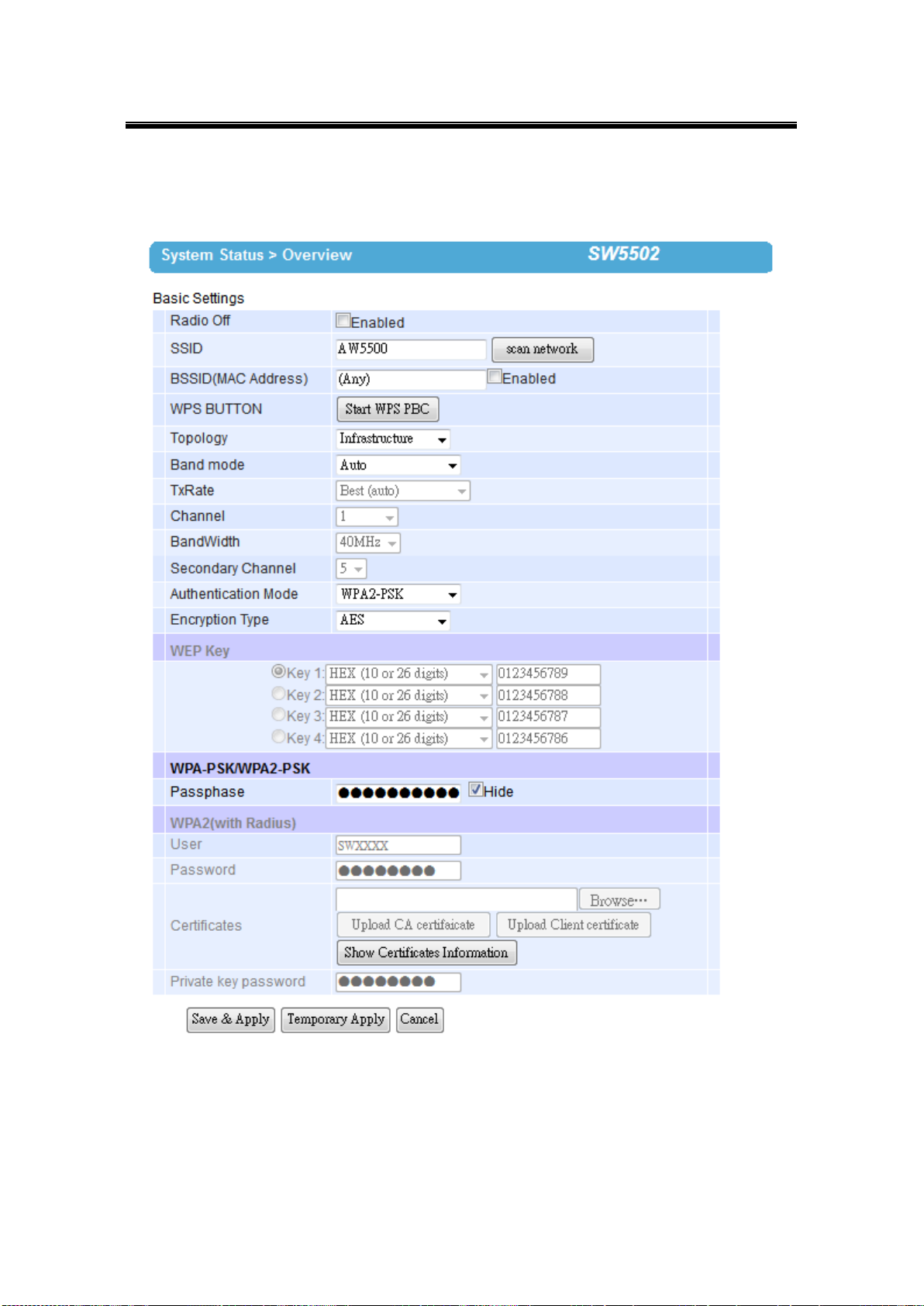
Atop Industrial Wireless Serial Device Server Series
SW550X
User Manual V 1.1
4.3.2 Configure SW550X as a Wireless Client in the Infrastructure mode (PSK)
Fig. 4. 20
78
Page 85

Atop Industrial Wireless Serial Device Server Series
SW550X
User Manual V 1.1
Topology
Infrastructure
Band Mode
Auto
Tx Rate
Auto
Channel
Disabled (auto sensing)
Authentication
As defined by the Access Point
Encryption
As defined by the Access Point
WPA2-PSK passphrase
8~63 characters
Attention
We recommend using WPA2-PSK authentication with AES encryption as it is
the most secure password-type security option without utilizing 802.1x.
Configure your device as explained below.
Table 4. 4
4.3.3 Click -2-Go
It is possible to pair up two SW550X in Ad-Hoc mode or have it connect to AW5500
(Infrastructure) automatically without entering the Web UI. Refer to Serial Manager’s manual
for more details on this.
79
Page 86

Atop Industrial Wireless Serial Device Server Series
SW550X
User Manual V 1.1
4.3.4 Configure SW550X as a Wireless Client in the Infrastructure mode (PEAP-MSCHAPv2)
Fig. 4. 21
Configure your device as explained below.
80
Page 87

Atop Industrial Wireless Serial Device Server Series
SW550X
User Manual V 1.1
Topology
Infrastructure
Band Mode
Auto
Tx Rate
Auto
Channel
Disabled (auto sensing)
Authentication
WPA2 (PEAP)
Encryption
As defined by the Access Point
Username
Defined by the RADIUS Server
Password
Defined by the RADIUS Server
Table 4. 5
81
Page 88
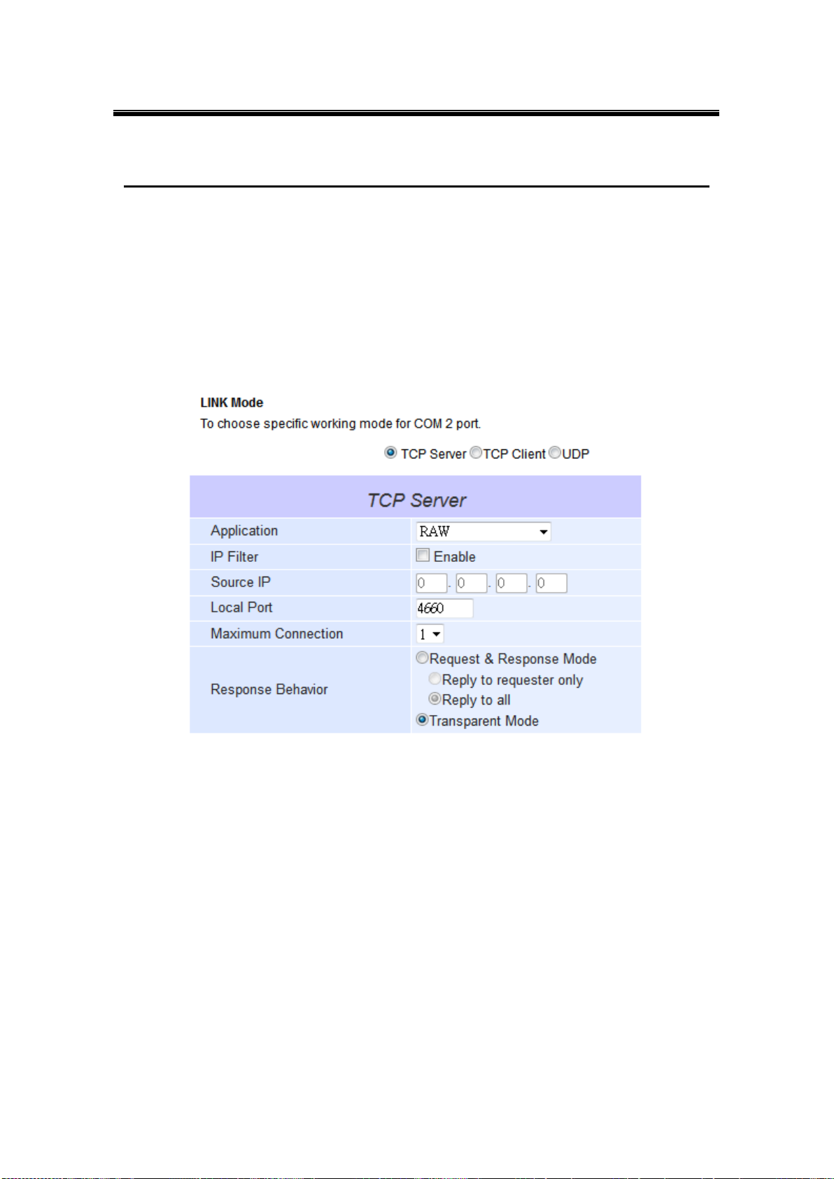
Atop Industrial Wireless Serial Device Server Series
SW550X
User Manual V 1.1
5 VCOM Installation & Troubleshooting
5.1 Enabling VCOM
SW550X will encapsulate control packets on top of the real data when Virtual COM is enabled.
This will allow the Virtual COM port in the Windows/Linux system to access SW550X’s COM
ports. Remember that VCOM can only be enabled on TCP Server Mode (Fig. 5. 2) or TCP
Client (Fig. 5. 1).
Fig. 5. 2
82
Page 89
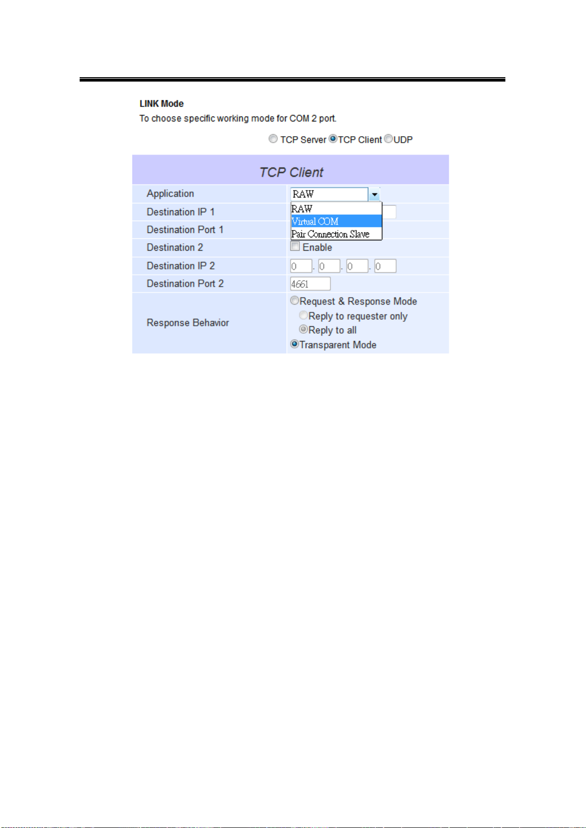
Atop Industrial Wireless Serial Device Server Series
SW550X
User Manual V 1.1
Fig. 5. 3
Virtual COM allows remote access of serial devices over TCP/IP networks through Serial/IP
Virtual COM ports that work like local native COM ports. Fig. 5. 4 is a Virtual COM connection
diagram.
83
Page 90

Atop Industrial Wireless Serial Device Server Series
SW550X
User Manual V 1.1
Fig. 5. 4
84
Page 91

Atop Industrial Wireless Serial Device Server Series
SW550X
User Manual V 1.1
5.1.1 VCOM driver setup
System Requirements
Windows Platform (32/64 bits)
Win7
2008
Vista
XP
2003 (also Microsoft 2003 Terminal Server)
2000 (also Microsoft 2000 Terminal Server)
NT (also Microsoft NT Terminal Server)
4.0
9x
Citrix MetaFrame Access Suite
Linux, also available but first you might need to download a separate package called
Virtual COM driver for Linux (TTYredirector) available for download on Atop website or
in the product CD. The zipped package includes a binary file for installation and a manual
for Linux systems.
5.1.2 Limitation
The Virtual COM driver allows up to 256 Virtual COM ports in a single PC. Selecting in the
range from COM1 to COM4096 is allowed. Note that COM ports already occupied by the
system or other devices will not be available.
85
Page 92

Atop Industrial Wireless Serial Device Server Series
SW550X
User Manual V 1.1
5.1.3 Installation
Run the Virtual COM setup file included in the CD or download a copy from our website to
install the Virtual COM driver for the operating system. Turn off your anti-virus software and try
again if installation fails. At the end of the installation, please select at least one Virtual COM
port from the Serial/IP Control Panel.
5.1.4 Uninstalling
1 From Windows Start Menu select Control Panel, Add/Remove Programs.
2 Select Serial/IP Version x.x.x in the list of installed software.
3 Click the Remove button to remove the program.
86
Page 93

Atop Industrial Wireless Serial Device Server Series
SW550X
User Manual V 1.1
5.2 Enable VCOM Serial device servers and select VCOM in Windows
5.2.1 Enable VCOM in Serial device servers
Enable Virtual COM in our serial device servers by logging into our WebUI. It is located under
COM configuration. The following figures show how to enable Virtual COM in SW550X. For a
detailed Link Mode configuration with Virtual COM, please refer to the previous chapter
starting from Sec. 4.1 on Link Mode configurations.
Fig. 5. 5
87
Page 94

Atop Industrial Wireless Serial Device Server Series
SW550X
User Manual V 1.1
5.2.2 Running Serial/IP in Windows
Find Serial/IP Control Panel from:
Start → All Programs → Serial/IP → Control Panel
In the Windows Control Panel, open the Serial/IP applet.
In the Windows notification area, Fig. 5. 6; right click in the Serial/IP tray icon and
click on Configure to open the Control Panel.
Fig. 5. 6
If no Virtual COM port is selected, a dialog will pop up and asks to select at least one port as
the Virtual COM port before proceeding, Fig. 5. 7.
88
Page 95

Atop Industrial Wireless Serial Device Server Series
SW550X
User Manual V 1.1
Fig. 5. 7
After at least one Virtual COM port is selected, the Control Panel will show, Fig. 5. 8.
89
Page 96
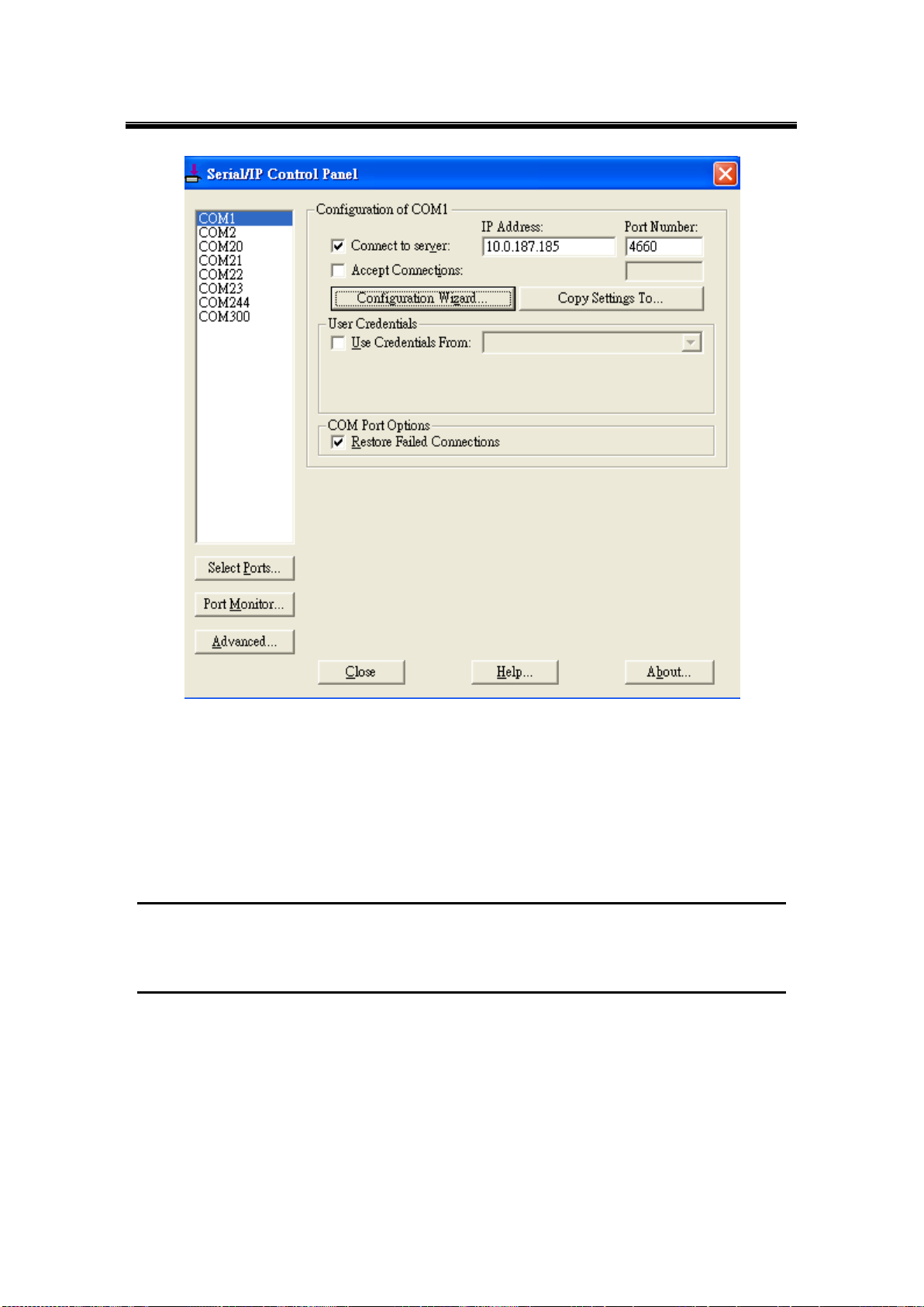
Atop Industrial Wireless Serial Device Server Series
SW550X
User Manual V 1.1
Fig. 5. 8
The left hand side of the Control Panel shows the list of selected Virtual COM ports. Click on
Select Ports to add or remove Virtual COM ports from the list. The right hand side of the
Control Panel shows the configurations of the selected Virtual COM port marked in blue. Each
Virtual COM port can have its own settings.
Note: The changes to Virtual COM ports apply immediately, so there is no need to save the settings manually.
However, if the Virtual COM port is already in use, it is necessary to close the Virtual COM port and open it after the
TCP connection closes completely in order for the changes to take effect.
90
Page 97
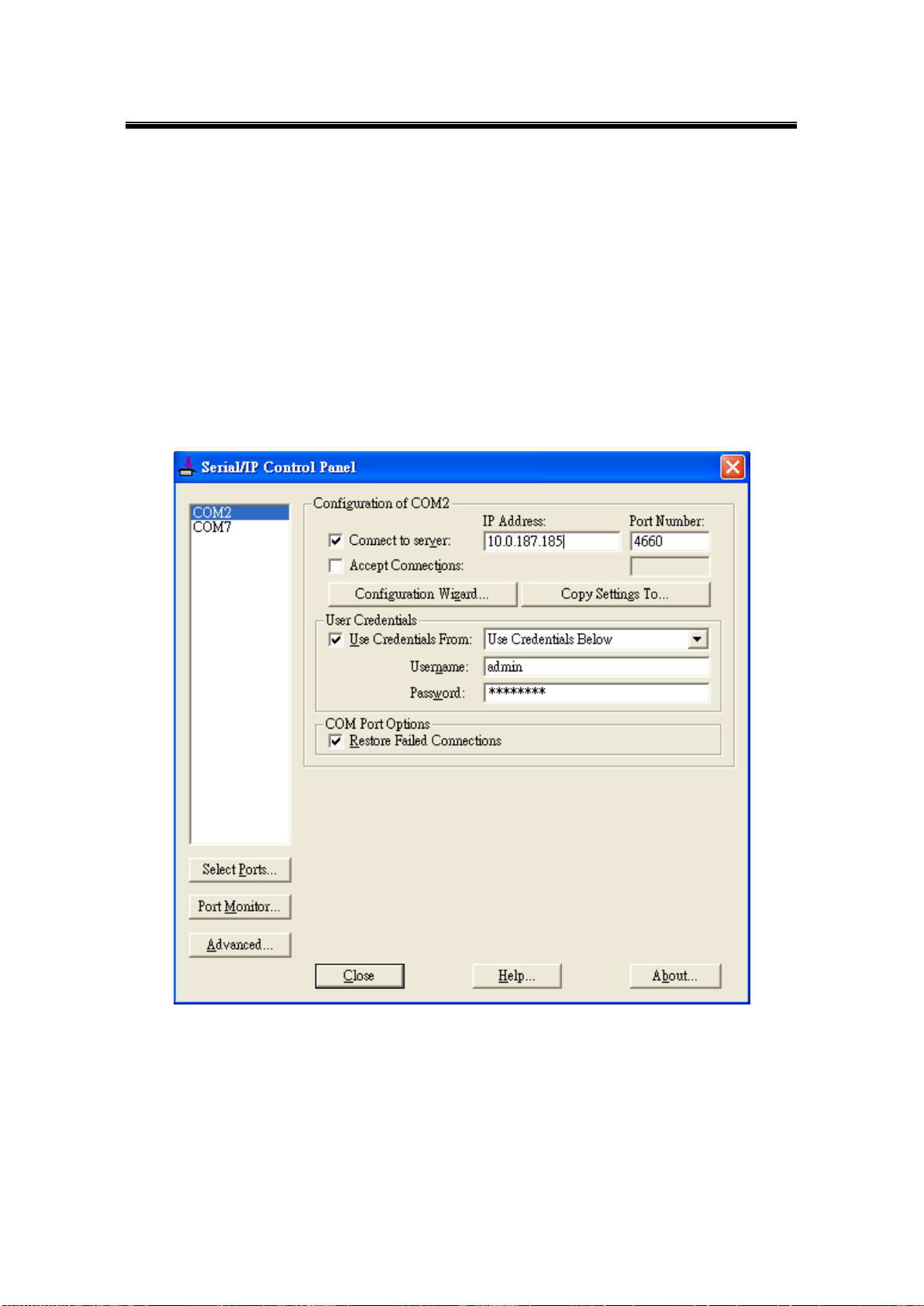
Atop Industrial Wireless Serial Device Server Series
SW550X
User Manual V 1.1
5.2.3 Configuring VCOM Ports
1. If the serial device server is running in TCP Server mode (recommended), a
Serial/IP should be the TCP Client connecting to the serial device server. Enable
Connect to Server and enter the IP Address of the serial device server with the
Port Number specified. The Port Number here is the Local Listening Port for the
serial device server.
2. If the serial device server is running in TCP Client mode, Serial/IP should be the
TCP Server waiting for a serial device server to connect it. Enable Accept
Connections and enter the Port Number. The Port Number here is the
Destination Port of the serial device server. Do not enable Connect to Server and
Accept Connections together.
Fig. 5. 9
91
Page 98
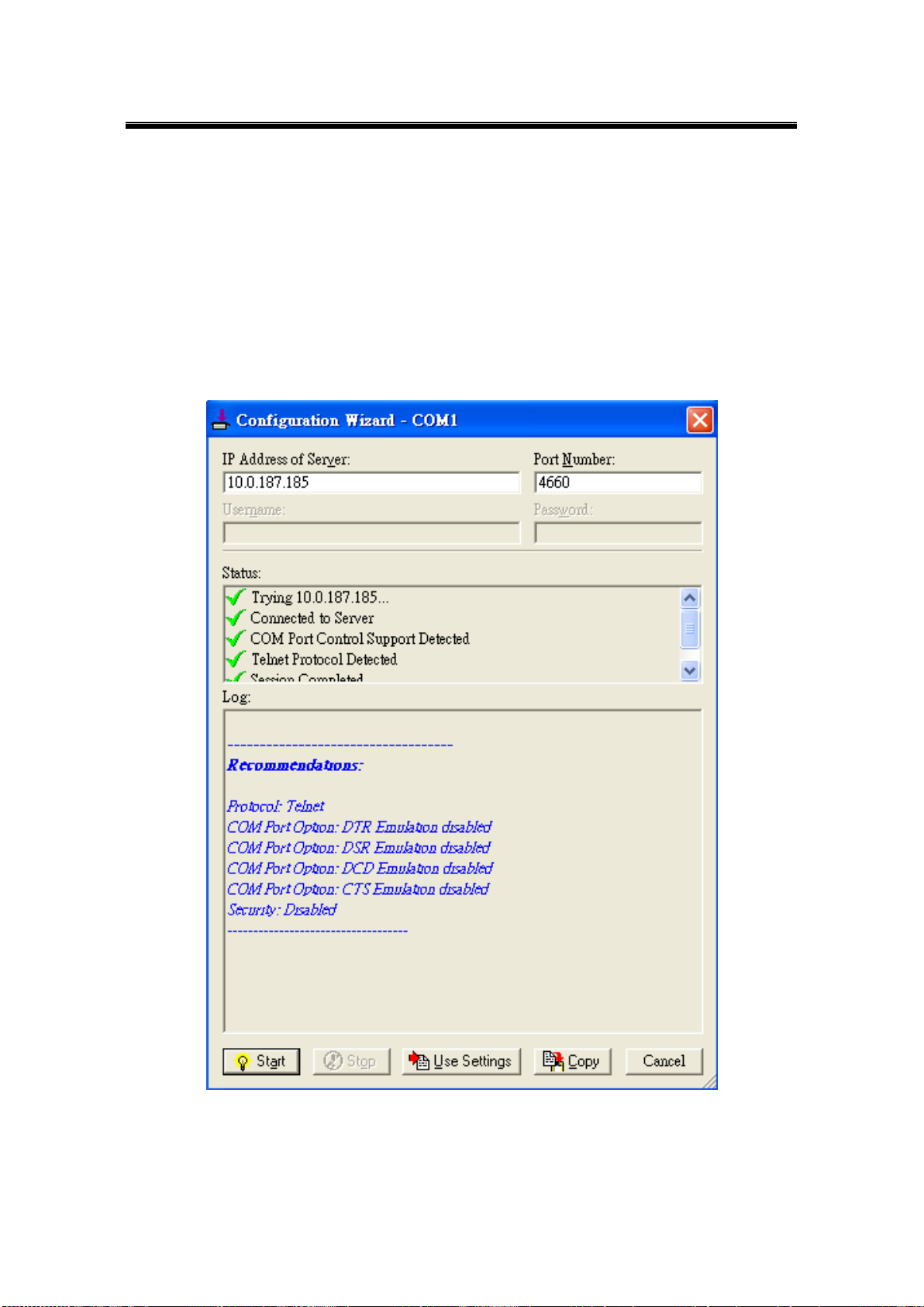
Atop Industrial Wireless Serial Device Server Series
SW550X
User Manual V 1.1
3. Enable Restore Failed Connections to force Virtual COM to automatically restore
failed connections with the serial device server in the case of unstable network
connections.
4. To test the Virtual COM connection, click the Configuration Wizard button and then
click Start button in the pop up window (Fig. 5. 10). If the test passes, all checks
should be in green. To apply the changes in the Configuration Wizard window to
the Control Panel, click on Use Settings. Click on Copy to copy the results to the
system clipboard.
5. To transfer the settings between Virtual COM ports, click on the Copy Settings To
button.
Fig. 5. 10
92
Page 99

Atop Industrial Wireless Serial Device Server Series
SW550X
User Manual V 1.1
93
Page 100
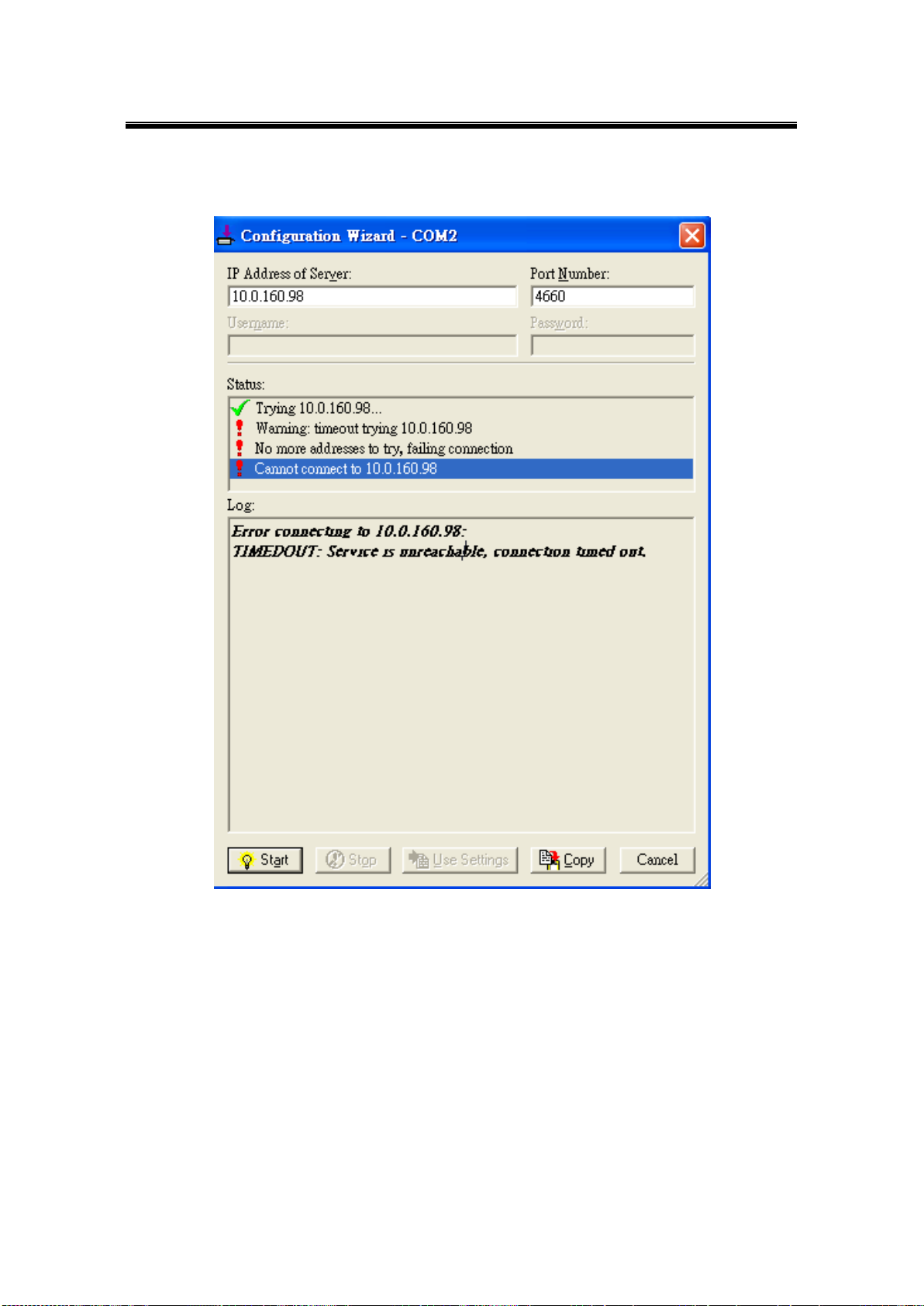
Atop Industrial Wireless Serial Device Server Series
SW550X
User Manual V 1.1
5.3 Exceptions
Fig. 5. 11
If the exclamation mark begins with Warning: timeout trying x.x.x.x as in Fig. 5. 11, recheck
the VCOM IP and Port configuration or the PC’s network configuration.
94
 Loading...