

Techn olo gie s
Atop Technologies, Inc.
Industrial Wireless Serial Device Server
SW550X Series
Hardware Installation Guide
Version 1.0
Updated on June, 2012
F.G
V-
V+
ANT1
100
SAB
80
ON
12 3
60
COM1
40
20
Status
Tx Rx
COM1
COM2
ON SAB
1 2 3 4 5 6
WLAN
RUN
COM
COM2
RUN
LAN
ANT2
Reset
Tel: 886-3-5508137
Fax: 886-3-5508131
www.atop.com.tw
P/N: 89900409G
ANT1
COM
RUN
ANT2
F.G
V-
V+
SAB
ON
1 2 3
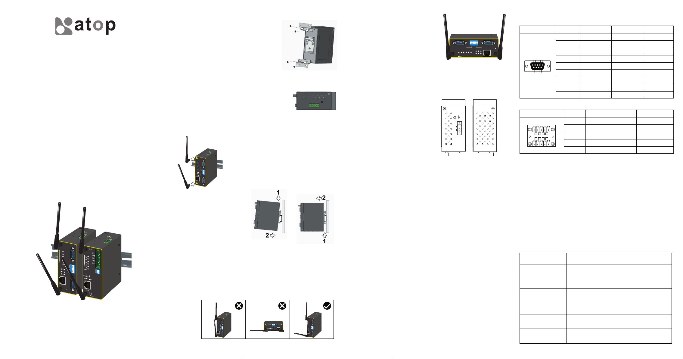
Installation Overview
The device’s appearance is as in the figure below.
There are mounting plates and screws that come
1.
inside the package. Proceed to place the screws
on the back of the device as shown in (Fig. 1).
There is a screw close to the power terminal
2.
block this screw is used to connect the grounding
of the SW550X.
Although internal grounding has been done
inside, in order to ensure overall maximum
performance and protect your device it is still
strongly advised to link this point to the ground as
well; hazardous ESD can come into contact with
it and damage your equipment. On the terminal
block, there is a terminal for Frame Ground, you
can choose whether to connect it the grounding,
you may opt between only one of these two
grounds ( the one chosen should be connected at
all times).(Fig. 2)
Proceed then to fix the antennas to the female
3.
RP-SMA connectors deemed to, (Fig. 3).
You can then choose whether to place the terminal
F.G
V-
V+
ANT1
100
80
SAB
ON
60
COM1
40
20
Status
Tx Rx
COM1
COM2
WLAN
RUN
COM
COM2
RUN
LAN
ANT2
Reset
(Fig. 3)
123
ON SAB
1 2 3 4 5 6
block at this point or do it later depending on the
actual location of the device or level of comfort for
performing such operation.
Once the plate has been firmly put in place,
4.
proceed to mount the whole device as shown in
(Fig. 4).
Proceed to (Fig. 5) if you want
to remove the device from
DIN-Rail.
(Fig. 4) (Fig. 5)
Next we can then proceed to connect the device to the LAN (switch or
5.
PC, depending on the case), take care on using an RJ45
terminal/connector; after this we can then proceed to the device’s
settings.
Other points to take into consideration when installing the device follow next.
■
The antennas are 3dBi (at 2.4 GHz) and a 5 dBi (at 5GHz); once fixed
to the rail, do not place them parallel, otherwise their signal will
interfere with each other.
F.G
V-
V+
ANT1
100
80
SAB
ON
123
60
COM1
40
20
Status
Tx Rx
COM1
COM2
ON SAB
1 2 3 4 5 6
WLAN
RUN
COM
COM2
RUN
LAN
ANT2
Note:
Reset
The first two pictures illustrate not recommended setup for the SW550X;
signal will strongly decrease with the antennas on this position.
1 2 3 4 5 6
ON SAB
123
COM1
COM2
ON
SAB
RUN
Reset
ANT1
ANT2
Tx Rx
LAN
806040
20
100
RUN
Status
COM
COM2
WLAN
COM1
(Fig. 1)
(Fig. 2)
F.G
V-
V+
ANT1
100
80
SAB
ON
123
60
COM1
40
20
Status
Tx Rx
COM1
COM2
ON SAB
1 2 3 4 5 6
WLAN
RUN
COM
COM2
RUN
LAN
ANT2
Reset
■
If the device is not going to be placed on
the rail and to be positioned horizontally,
then the antennas could be setup making
a “V” shape,(Fig. 6).
ANT1
■
The openings to the sides are for the device’s heat dissipation and
1 2 3 4 5 6
ON SAB
12 3
COM1
ON
SAB
806040
100
COM2
RUN
Reset
Tx Rx
20
Status
COM1
ANT2
LAN
RUN
COM
COM2
WLAN
(Fig. 6)
there may be inside hazardous voltages, please never obstruct or
cover them with any objects or try to
insert them through it.
F.G.
V-
V+
■
SW550X’s factory IP by default is 10.0.50.100 you can access the
device by its Web UI once it is connected to a physical network (or
using Serial Manager, for more information on Serial Manager,
please refer to the manual, Chapter 3). Please be aware that the PC
needed for this procedure needs to be in the same subnet, or you
may refer yourself to the User’s Manual on Sec. 3.1.
Field Maintenance and Service
If the device requires servicing of any kind, you may need to disconnect
and remove it from its mounting. The initial installation should be done
in a way that makes this as convenient as possible.
■
Voltage/Power lines should be properly insulated as well as other
cables. Be careful when handling them so as to not trip over.
■
Do not under any circumstance insert foreign objects of any kind into
the heat dissipation holes located in the different faces of the device.
This may not only harm the internal layout but might cause harm to
you as well.
■
Do not under any circumstance open the device for any reason.
Please contact your dealer for any repair needed or follow the
instructions on section of your User’s manual.
Pin Assignments
9-pin D-sub Connector for RS-232/422/485
1 2 3 4 5
6 7 8 9
Pin
1
2
3
4
5
6
7
8
9
RS-232
DCD
RXD
TXD
DTR
SG
DSR
RTS
CTS
RI
RS-422
N/A
TXD+
RXD+
N/A
SG
N/A
RXD-
TXD-
N/A
RS-485
N/A
N/A
DATA+
N/A
SG
N/A
DATA-
N/A
N/A
5-pin Terminal Block for RS-422/485
1 2 3 4 5
1 2 3 4 5
Pin
1
2
3
4
5
RS-422
TXD+
TXD-
RXD+
RXD-
SG
RS-485
N/A
N/A
DATA+
DATA-
SG
Package Check List
Inside the package you will find the following items:
■
Industrial Wireless Serial Device Server SW550X x 1
■
3 ~ 5 dBi antenna x 2
■
3-Pin 5.08mm Lockable Terminal Block x 1
■
5-Pin 5.08mm Lockable Terminal Block x 1 (fo r SW5501- TB, S W5501-Sis )
■
5-Pin 5.08mm Lockable Terminal Block x 2 (fo r SW5502- TB, S W5502-Sis )
■
Din Rail Kit x 1 (Already mounted to the device)
■
Installation Guide + Warranty Card x 1
■
CD (User’s Manual / Installation Guide / Serial Manager Utility) x 1
Optional Accessories
Item Description
US315-12 (US-Y)
Power Adapter
USE315-12 (EU-Y)
Power Adapter
ADP-DB9(F)-TB5
WMK-454-Black Black Aluminum Wall Mount Kit
Y-Type (5.08 mm) power adaptor,
100-240VAC input, 1.25A @ 12VDC output,
US plug
Y-Type (5.08 mm) power adaptor,
100-240VAC input, 1.25A @ 12VDC output,
EU plug
Female DB9 to Female 3.81 TB5 Converter
LED Indicators
Name
COM
LAN
WLAN
RUN
Color
Green
Orange
Green
Green
Green
Status
Blinking
Off
Blinking
On
Off
Blinking
On
Blinking
Off
Off
Blinking
Steadily
Blinking
Rapidly
Signal LEDs
Operations
Searching for an AP
Connecting
Connected
Cannot connected to the AP
No IP provided by the DHCP
Server
Signal Strength is less 20%
Bad Signal Strength (20%-40%)
Poor Signal Strength
Fair Signal Strength (60%-80%)
Good Signal Strength
Excellent Signal Strength
(95%-100%)
Description
Data transmitting on the serial port
Data is not transmitting on the serial port
Ethernet is connected on 10Mbps
Ethernet is connected on 100/1000Mbps
Ethernet is disconnected
Data is transmitting on Ethernet
Wireless Radio is enabled
Wireless Radio is enabled and data is
transmitting
Wireless Radio is disabled
System is not powered on
AP firmware is running normally
AP firmware is not running
Status LED1 LED2 LED3 LED4 LED5
☼
☼
☼
☼
☼
☼
☼
☼
●
●
●
(40%-60%)
(80%-94%)
●
●
●
●
●
●
●
●
●
●
●
●
●
●
●
●
●☼●
off ●on ☼blinking
○
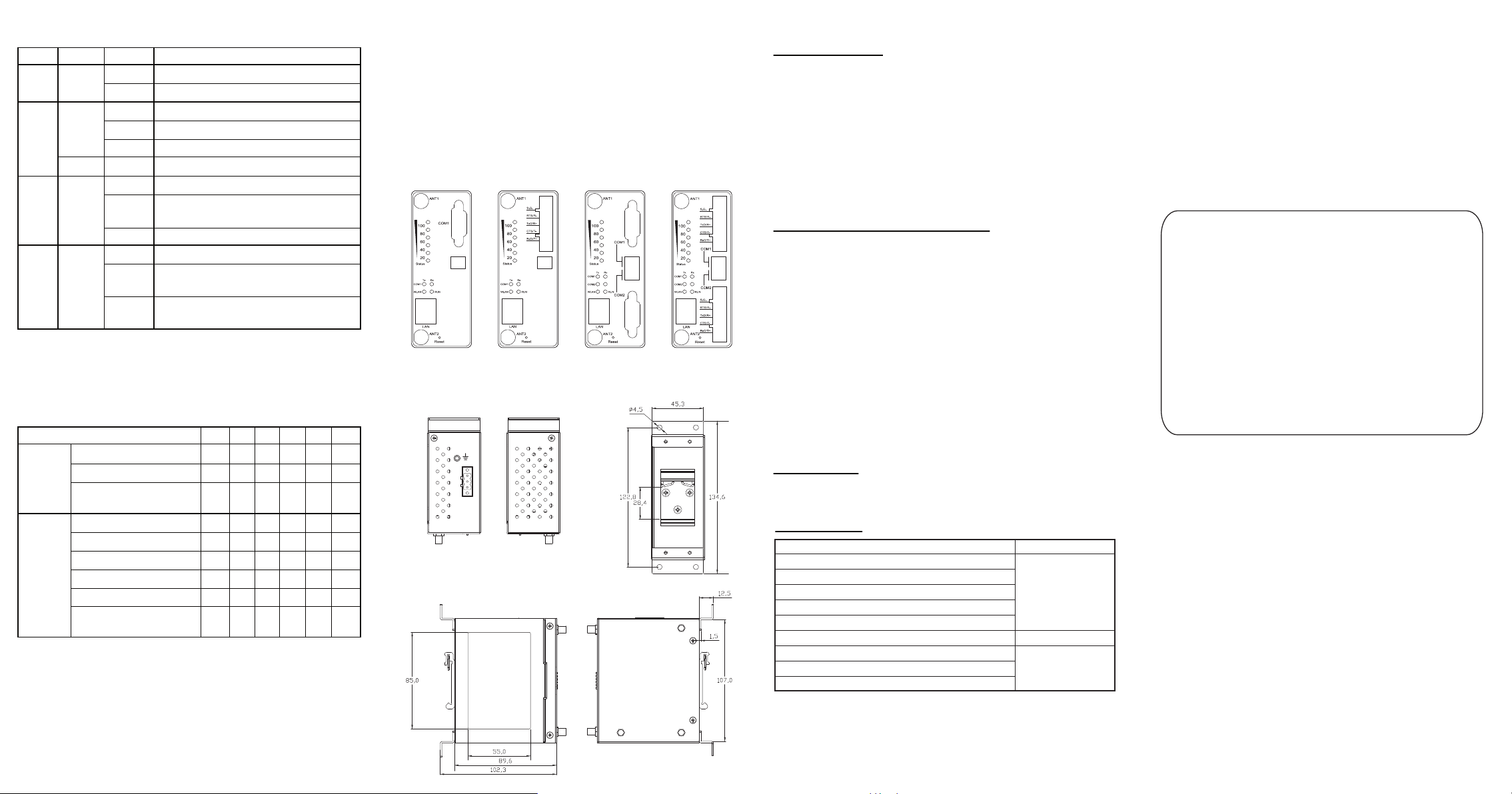
Device Dimensions,
Physical Appearance and Mounting
Proceed to mount the SW550X in a dry location free from dirt and
corrosive vapors, for more questions on environmental limitations
please refer to the User’s manual.
■
Unit Dimensions and Layout (unit=mm)
The Industrial Wireless Serial Device Server and dimensions are
shown below.
SW5501
SW5501-TB/Sis SW5502 SW5502-TB/Sis
F.G.
V-
V+
Left Side View Right Side View
Front View
Rear ViewTop and Bottom View
Warranty Policy
Warranty Conditions
Products supplied by Atop Technologies are covered in this warranty for
sub-standard performance or defective workmanship. The warranty is
not, however, extended to goods damaged in the following
circumstances:
(a) Excessive forces or impacts
(b) War or an Act of God: wind storm, fire, flood, electric shock,
earthquake
(c) Use of unqualified power supply, connectors, or maintenance
procedure
(d) Replacement with unauthorized parts
RMA and Shipping Costs Reimbursement
Customers shall always obtain an authorized "RMA" number from Atop
before shipping the goods to be repaired to Atop. When in normal use,
a sold product shall be replaced with a new one within 3 months after
purchase. The shipping cost from the customer to Atop will be
reimbursed by Atop.
After 3 months and still within the warranty period, it is up to Atop
whether to replace the unit with a new one; normally, as long as a
product is under warranty, all parts and labor are free of charge to the
customers.
After the warranty period, the customer shall cover the cost for parts
and labor.Three months after purchase, the shipping cost from the
customer to Atop will not be reimbursed, but the shipping cost from
Atop to the customer will be paid by Atop.
Limited Liability
Atop shall not be held responsible for any consequential losses from
using Atop’s product.
Warranty Period
Product Categories
Ethernet Switches
Wireless
Serial Device Servers
Modbus Gateways
Embedded Device Servers
DIN-Rail Power Supplies
Power Adaptors
Antennas
Other Accessories
Warranty
5 Years
3 Years
1 Year
The warranty certification will not be effective until an authorized stamp
issued by Atop’s overseas agents.
Purchase Date: / / (yyyy/mm/dd)
Serial Number:
ATOP Customer Services and Supports
1. Please contact your local dealers or Atop Technical Support Center at
the following numbers.
+ 886-3-550-8137 (Atop Taiwan)
+ 86-21-6495-6232 (Atop China)
2. Please report the defected problems via Atop’s Web site or E-mail
account
Web Site:www.atop.com.tw, e-mail:service@atop.com.tw
Web Site:www.atop.com.cn, e-mail:service@atop.com.cn
─ Any change by website in material announcement primarily. ─
 Loading...