

Page 1

SE8502-M12 Series
IP68 Rated 2-Port Serial Server
User’s Manual
Version 1.1
Updated on December 31, 2010
TEL: 886-3-5508137
FAX: 886-3-5508131
http://www.atop.com.tw
Page 2

User manual Version 1.1
SE8502-M12 IP68 Serial Server
Important Announcement
The information contained in this document is the property of Atop Technologies, Inc. and is supplied for the sole
purpose of operation and maintenance of products of Atop Technologies, Inc. No part of this publication is to be used
for any other purposes, and it is not to be reproduced, copied, disclosed, transmitted, stored in a retrieval system, or
translated into any human or computer language, in any form, by any means, in whole or in part, without the prior
explicit written consent of Atop Technologies, Inc.
Published by
Atop Technologies, Inc.
2F, No. 146, Sec. 1, Tung-Hsing Rd.
Jubei, Hsinchu 30261
Taiwan, R.O.C.
Tel: 886-3-5508137
Fax: 886-3-5508131
www.atop.com.tw
Copyright © 2010 Atop Technologies, Inc. All rights reserved.
All other product names referenced herein are registered trademarks of their respective companies.
Copyright © 2010 Atop Technologies, Inc.
All rights reserved
II
Page 3

User manual Version 1.1
SE8502-M12 IP68 Serial Server
Contents
1.1. OVERVIEW ......................................................................................................................................................1
1.2. FEATURES........................................................................................................................................................1
1.3. PACKAGE CHECKLIST......................................................................................................................................2
1.4. INTERFACES ....................................................................................................................................................2
1.5. PANEL/WALL MOUNTING................................................................................................................................3
2.1. DEFAULT SETTINGS.........................................................................................................................................5
2.1.1. Configure IP by SerialManager Utility......................................................................................6
2.1.2. Configure IP by web interface..................................................................................................7
2.1.3. Configure IP by Telnet utility....................................................................................................7
2.1.4. Auto IP with DHCP...................................................................................................................7
2.2. TCP/IP PORT NUMBER....................................................................................................................................7
2.3. TCP & UDP PROTOCOLS ................................................................................................................................8
2.3.1. Transmission Control Protocol (TCP)......................................................................................8
2.3.2. User Datagram Protocol (UDP)...............................................................................................8
2.4. CONNECTIVITY TOPOLOGY .............................................................................................................................8
2.4.1. Virtual COM Mode...................................................................................................................8
2.4.2. Tunneling Mode .....................................................................................................................10
3.1. LOGIN TO SYSTEM.........................................................................................................................................11
3.2. GENERAL INFORMATION ...............................................................................................................................12
3.3. NETWORK CONFIGURATIONS ........................................................................................................................13
3.3.1. LAN Settings..........................................................................................................................15
3.3.2. DNS Settings.........................................................................................................................15
3.3.3. SNMP Settings.......................................................................................................................15
3.4. COM PORT CONFIGURATION ........................................................................................................................16
3.4.1. Link Mode Settings................................................................................................................16
3.4.2. TCP Server Mode..................................................................................................................17
3.4.3. TCP Client Mode....................................................................................................................17
3.4.4. UDP Mode.............................................................................................................................18
3.4.5. Serial Settings........................................................................................................................18
3.4.6. Delimiter Settings...................................................................................................................19
3.5. CONFIGURE SYSTEM .....................................................................................................................................19
3.5.1. Configure Time by NTP Service............................................................................................20
3.5.2. Security (change the Password)............................................................................................20
3.5.3. Restoring Factory Default Configurations..............................................................................21
3.5.4. Restart System......................................................................................................................21
4.1. GENERAL INFORMATION ...............................................................................................................................23
4.2. NETWORKING CONFIGURATION.....................................................................................................................24
4.2.1. LAN Settings..........................................................................................................................25
4.2.2. DNS Settings.........................................................................................................................25
4.2.3. SNMP Settings.......................................................................................................................26
Copyright © 2010 Atop Technologies, Inc.
All rights reserved
III
Page 4

User manual Version 1.1
SE8502-M12 IP68 Serial Server
4.3. COM PORT CONFIGURATION ........................................................................................................................26
4.3.1. TCP Server Mode for Link Mode...........................................................................................27
4.3.2. TCP Client for Link Mode.......................................................................................................28
4.3.3. UDP for Link Mode ................................................................................................................28
4.3.4. Serial Settings........................................................................................................................29
4.3.5. Packet Delimiter.....................................................................................................................30
4.4. SECURITY CONFIGURATION...........................................................................................................................31
4.4.1. Change the Password ...........................................................................................................32
A.1 PRE-INSTALLATION REQUIREMENTS...................................................................................................................33
A.2 APPLYING TO THE SE8502-M12.........................................................................................................................33
A.3 VIRTUAL COM COMMUNICATION ......................................................................................................................34
APPENDIX B. CONFIGURATION UTILITY .......................................................................................................37
B1. SERIALMANAGER UTILITY INTRODUCTION.........................................................................................................37
B2. INTERFACE..........................................................................................................................................................37
B3. FUNCTIONS.........................................................................................................................................................37
APPENDIX C. EMERGENCY SYSTEM RECOVERY ........................................................................................54
C1. SYSTEM RECOVERY PROCEDURES......................................................................................................................54
HARDWARE SPECIFICATIONS.....................................................................................................................................56
Copyright © 2010 Atop Technologies, Inc.
All rights reserved
IV
Page 5

User manual Version 1.1
SE8502-M12 IP68 Serial Server
1. Introduction
1.1. Overview
SE8502-M12 is an Industrial 2-Port IP68 Serial Server, built for the uses of waterproof, dustproof, and vibrationresistant.
There is a strong demand for reliable and rugged networking solutions, that can be used for the industrial workplace
where is in harsh environmental conditions, such as high levels of moisture, dust, heat, electrical interference, and
vibration. SE8502-M12 is a device that has IP68-rated housing and M12 metal connectors. It also provides a wide
working temperature range from -40 ~ 75°C.
SE8502-M2 supports multiple link mode with TCP server/client, UDP and VirtualCOM, can be configured by
Windows Base utility. In addition, M12 connectors can secure a firmly connecting, and preven t loose from vibrating
condition, such as in moving vehicles.
1.2. Features
z 15KV ESD protection for serial signals
z 10/100Mbps Fast Ethernet full duplex auto negotiation
z Support multiple link mode with TCP server/client, UDP and Virtual COM mode
z Monitor, manage and control industrial field devices remotely
z Configuration: Built-in Web Server /Serial Console/ Telnet
z Two serial COM ports support RS-232/RS-485/RS-422 by Software Selectable
z Windows Base utility for IP configuration
z Upgrade firmware from remote-PC via Ethernet
z Rigid aluminum case design complies with IP68 standard
z Wide temperature range : -40 ~ 75°C
z Field-style mounting
Copyright © 2010 Atop Technologies, Inc.
All rights reserved
1
Page 6
User manual Version 1.1
SE8502-M12 IP68 Serial Server
1.3. Package Checklist
Your SE8502-M12 is shipped with the following items. If any of these items is missing or damaged, please contact
your customer service representative for assistance.
SE8502-M12
Quick Start Guide.
Product CD with user’s manual and configuration utility “ SerialManager”
NOTE: Notify your sales representative if any of the above items is missing or damaged.
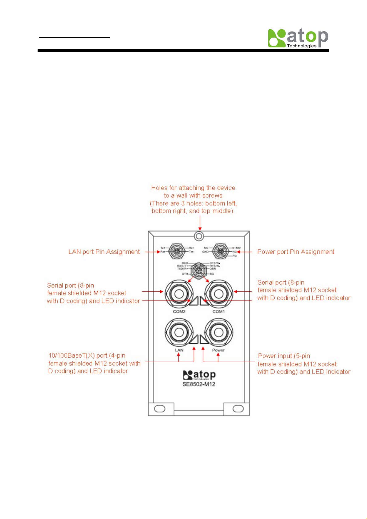
1.4. Interfaces
SE8502-M12 Panel Layouts
Copyright © 2010 Atop Technologies, Inc.
All rights reserved
2
Page 7

User manual Version 1.1
SE8502-M12 IP68 Serial Server
1.5. Panel/Wall Mounting
To mount the SE8502-M12on the panel or wall, please follow up the steps below,
1. Select three proper screws and make holes on the panel or wall.
2. Insert the first screw into the top screw hole and screw it into panel or wall firmly.
3. Insert the another two screws into the two bottom holes and screw them into panel or wall firmly. .
Notice:
The SE8502-M12 is designed to be mounted to a well-grounded mounting
surface .Please confirm the SE8502- M12 is mounted firmly before doing the cabling.
■ 1.6 Grounding the SE8502-M12
Proper grounding will minimize the effects of noise due to electromagnetic interference (EMI).
Please install the ground connection from the ground screw to the grounding surface before connecting the devices.
Copyright © 2010 Atop Technologies, Inc.
All rights reserved
3
Page 8
User manual Version 1.1
SE8502-M12 IP68 Serial Server
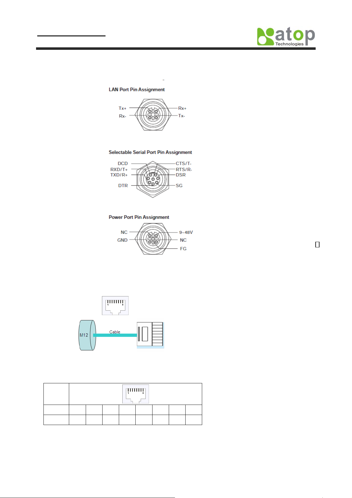
1.7 Pin assignment of LAN/ Serial / Power port
There are two wiring diagrams for straight-through and cross-over Ethernet cables.
RJ45(8-pin) to RJ45(8-pin) straight-through cable wiring
10/100BaseT(X) Ethernet Port Connection
RJ-45
Pin 1 2 3 4 5 6 7 8
Signal
RJ45(8-pin) to RJ45(8-pin) cross-over cable wiring
10/100BaseT(X) Ethernet Port Connection
Tx+ Tx- Rx+
NC = Not Assigned
Rx-
Copyright © 2010 Atop Technologies, Inc.
All rights reserved
4
Page 9

User manual Version 1.1
SE8502-M12 IP68 Serial Server
RJ-45
Pin 1 2 3 4 5 6 7 8
Signal
Rx+ Rx- Tx+
Tx-
2. Software Setup
Now the SE8502-M12 hardware is installed and power is on, network IP configuration will be set in this
section.
2.1. Default Settings
The SE8502-M12 has an IP addresses one for Ethernet interface. These default settings are shown from under
information
Default IP addresses
Interface Device IP Subnet mask Gateway IP
LAN port 10.0.0.50.100 255.255.0.0 10.0.0.254
The other default settings of SE8502-M12 are shown in the following table
Property Default V alue
Ethernet Port
IP Address 10.0.50.100
Gateway 10.0.0.254
Subnet Mask 255.255.0.0
Security
User Name
Password Null (Leave it blank)
Serial
COM 9600/None/ 8/1,No flow control, packet delimiter disabled
Link Mode TCP Server, Listen port 4660/4661,No Filter, Virtual COM disabled
SNMP
SysName of SNMP Name (System Name)
SysLocation of SNMP Location (System Location)
SysContact of SNMP Contact (System Contact)
Admin
Table 1. Default settings of the SE8502-M12 device
Copyright © 2010 Atop Technologies, Inc.
All rights reserved
5
Page 10
User manual Version 1.1
SE8502-M12 IP68 Serial Server
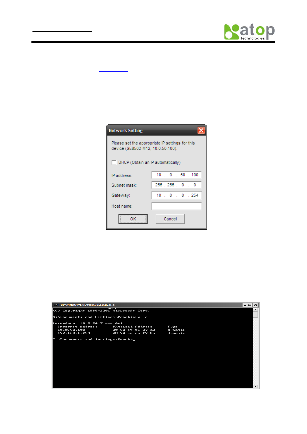
2.1.1. Configure IP by SerialManager Utility
Use SerialManager configuration utility that comes with product CD or diskette to configure the network parameters.
For more details, please refer to
Find new device and IP assignment
Use SerialManager Utility for finding new device IP address, get device’s current IP from table list
Re-assigned IP, network mask and gateway if need with SerialManager Utility.
User can configure User ID, Password and Host Name with SerialManager Utility.
Appendix B1.
Fig 2. IP settings for SerialManager Utility tool
Note: All settings were NOT changed if user ID or password was incorrect.
If there is more than one device using the same IP address in same Subnet. User has to correct mapping between MAC
address & IP address by ARP commands.
ARP commands
ARP (address resolution protocol) commands can be used to assign a static IP address on SE8501-M12 using its
hardware MAC (media access control) address. The MAC address"0060E9-xxxxxx" is printed on the rear side of
SE8502-M12. The following figure shows how to use ARP command on MS-DOS command prompt window.
Example: Set IP 10.0.50.100 to MAC address 00-60-e9-06-07-d2.
Fig 3. Map IP address to MAC address by ARP Command
Copyright © 2010 Atop Technologies, Inc.
All rights reserved
6
Page 11

User manual Version 1.1
SE8502-M12 IP68 Serial Server
Note: ARP commands can only be used to set a static IP address of SE8502-M12
- arp –a commands show the current mapping IP and MAC addresses.
- arp –s “IP address” “MAC address” mapping the IP address to specify MAC address.
2.1.2. Configure IP by web interface
Use common Web browser, ex. Microsoft Internet Explorer or Mozilla Firefox, to configure the network parameters of
SE8502-M12.
Open web browser, type in the IP address (default IP: 10.0.50.100) of SE8502-M12 to be configured.
Default user name is admin and default password is null (leave it blank).
Configure IP settings from web Network links page then click “Save Configuration” to save settings.
Click on ”Restart” button to make the change effective.
Please refer to contents of
.
Web Configuration section for more details.
2.1.3. Configure IP by Telnet utility
Use common Telnet utility, ex. Microsoft Hyper-terminal, to configure the network parameters of SE8502-M12.
Run command telnet “IP address” to telnet to SE8502-M12 .Default IP address is 10.0.50.100 and default
password is null (leave it blank).
Configure IP settings from network settings menu, and restart system after saved settings.
Please refer to
Telnet Configuration section for more details.
2.1.4. Auto IP with DHCP
DHCP server will automatically supply an IP address gateway address, and subnet mask to SE8502-M12. By
default, the DHCP client function on SE8502-M12 is disabled, user can activate the DHCP functions by the following
steps
Execute SerialManager Utility
Click on the IP address (of SE8502-M12)
Click “Config” to pop-up the static IP Dialog Window
Check on ”Auto IP”
Click “Config Now” (The SE8502-M12 will restart and obtain the IP from the DHCP server automatically)
2.2. TCP/IP Port Number
Default Port numbers of SE8502-M12 is 4660 (1st port) & 4661 (2nd Port) and it is associated with the serial port COM1
and COM2 respectively. After the application program connected to the TCP port 4660 (or 4661) on the SE8502-M12,
data of user’s application program are transmitted transparently to SE8502 and vice versa.
Application Connectivity
SE8502-M12 provides Tunneling and Virtual COM operation mode. The SE8502-M12 is designed to transmit data
between one-or-more serial devices to/from one-or-more TCP/IP devices through wireless or wire Ethernet, so
SE8502-M12 can enhance the accessibility of the serial device through the ubiquitous TCP/IP based Ethernet. The
connection distance limit is overcome by SE8502-M12. Examples of these devices are PLC controllers, card readers,
display signs, security controls, CNC controller, etc.
Copyright © 2010 Atop Technologies, Inc.
All rights reserved
7
Page 12

User manual Version 1.1
SE8502-M12 IP68 Serial Server
2.3. TCP & UDP Protocols
SE8502-M12 can be operated in two most common protocols TCP and UDP.
2.3.1. Transmission Control Protocol (TCP)
TCP provides a connection and a byte oriented data stream with control parameters such as flow control, multiple
ports option, and order delivery notification. Once the connection is established, data can be transmitted in both
directions. TCP guarantees data is transmitted from one node to the other node(s) in orderly. The protocol also
distinguishes the transmitted data for different applications (such as a Web server or an Email server) on the same
computer.
For redundant or dual-network connectivity purposes, SE8502-M12 offers two TCP operation Modes so users
may choose for their specific application, TCP Server Mode and TCP Client Mode.
2.3.2. User Datagram Protocol (UDP)
UDP is a faster datagram delivery protocol. User can configure SE8502-M12 to work in the UDP mode. UDP is
connectionless protocol and can transmit multicast data to/from a serial device to one/multiple h ost compu ter. Because
UDP is the connectionless protocol, UDP does not guarantee the reliability and orderly data streams like TCP protocol.
Datagram may arrive out of order or lose without notice. But the advantage of UDP is the speed. UDP is faster and
hence more attractive in time-sensitive applications.
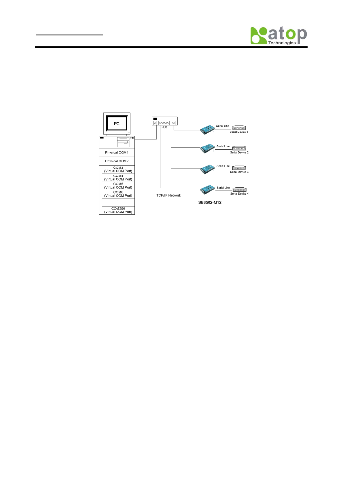
2.4. Connectivity Topology
SE8502-M12 is also equipped with Tunneling and Virtual COM operation modes. It is designed to transmit data
to/from multiple serial devices and from/to multiple TCP/IP devices on Ethernet, so it can enhance the accessibility of
the serial devices immensely. Fig 4. is the example of SE8502-M12 connection topology.
Fig 4. Typical Topology of SE8502-M12 Connection
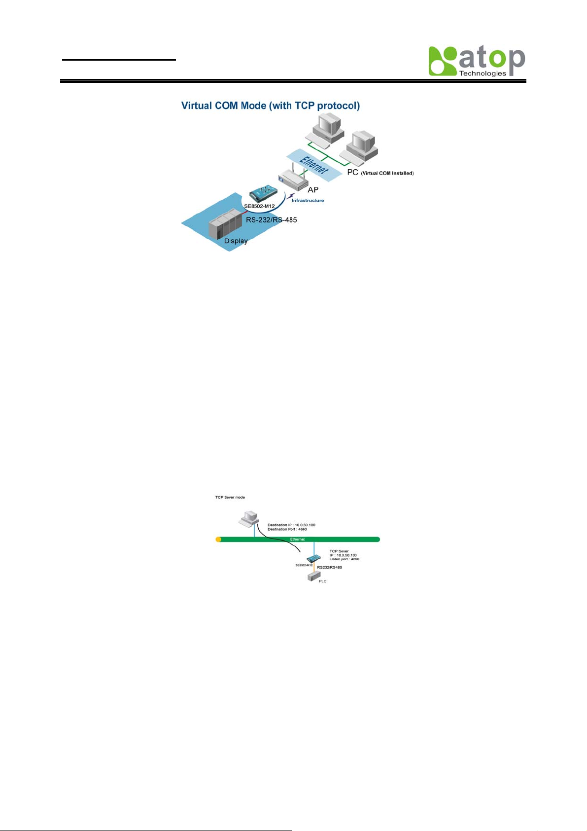
2.4.1. Virtual COM Mode
The Virtual COM software emulates a serial port with Internet or LAN topology. In the Virtual COM Mode, COM
port data (RS232) is encapsulated to Ethernet data format. By creating a virtual COM port on a PC, the Virtual COM
driver redirects communications from the virtual COM port to the destination IP address (and the designated port
number) by encapsulated COM data into IP data. Fig 5. illustrates a Virtual COM connection diagram.
Copyright © 2010 Atop Technologies, Inc.
All rights reserved
8
Page 13
User manual Version 1.1
SE8502-M12 IP68 Serial Server
Fig 5. TCP Connection in Virtual COM Mode
TCP Server in Virtual COM Mode
SE8502-M12 can be configured in the TCP server mode (PC as a client) with a unique IP and Port number, and
SE8502-M12 waits passively for the PC to establish a connection to. After the connection is established, PC can
communicate to serial devices through SE8502-M12.
Configure SE8502-M12 to be TCP server
Using one of the three configuration methods (Telnet, Web, and console), User can configure SE8502-M12 to be as
TCP Server as following.
Disabled the IP filter (default)
Set the port number (default port is 4660 for COM1, 4661 for COM2).
If IP filter is enabled, only the assigned source IP is allowed to be connected to SE8502-M12.
Fig 6. TCP Server in Virtual COM Mode
TCP Client in Virtual COM Mode
SE8502-M12 can be configured to be TCP Client mode (PC as a server) to establish a TCP connection to an
application server on PC, or the Remote Control Host. Once the connection is established, PC or Remote Con trol Host
can exchange data with several serial devices at the same time through SE8502-M12.
Configuring SE8502-M12 to be TCP client
User can configure SE8502-M12 to be as TCP Client for example, from Fig. 7. PC, as a server, has IP address
10.0.0.100 and listening on port 1000. Each SE8502-M12, connected with serial device, configured as TCP client
mode with destination IP address 10.0.0.100 and the destination port 1000, and the IP filter is disabled (by default).
Copyright © 2010 Atop Technologies, Inc.
All rights reserved
9
Page 14

User manual Version 1.1
SE8502-M12 IP68 Serial Server
Fig 7. TCP Client in Virtual COM Mode
2.4.2. Tunneling Mode
Tunneling Mode is used for multiple serial devices to “talk” among one another through SE8502-M12’s through
wireless LAN or wired Ethernet. This mode is particularly useful when two or more serial devices are far away. This
mode can be used to extend the normal serial communication distance of 15 m to 100 m or longer.
One SE8502-M12 can be configured to be the TCP Server Mode with serial device connected and also another
SE8502-M12 is configured as TCP client with serial device connected. After the connection is established, both serial
devices can exchange data to each other transparently. For example, User can implement SE8502-M12 tunneling mode
for Master /Slave mode PLCs or between other serial devices.
Fig 8. TCP Link in Tunneling mode
Configuring SE8502-M12 to Tunneling Mode
Using one of three configuration methods (Telnet, Web, or Console), user can configure SE8502-M12 to TCP Server
mode with a desired IP address and port, and with other SE8502-M12 is configured as TCP Clients mode with Server
IP and port as destination IP and port respectively.
Note: TCP client has to assign the destination IP and the destination port corresponding to TCP server’s IP and
listening port (example: TCP 4660 port).
Fig 9. TCP Tunneling Mode
Copyright © 2010 Atop Technologies, Inc.
All rights reserved
10
Page 15

User manual Version 1.1
SE8502-M12 IP68 Serial Server
UDP
In UDP mode, User may exchange Multicast data from one SE8502-M12 with multiple SE8502-M12s, Vice versa is
also true.
Fig 10. UDP Link in Tunneling mode
Configure SE8502-M12 in UDP Mode
Use one of the three configuration methods (Telnet, Web, and console). User can configure SE8502-M12 to UDP
mode. In UDP mode, SE8502-M12 can be configured to communicate to more than one node (Multicasting). Note that
the Multicast IP address is limited by the Class of IP address and subnet mask. As an example, for a network of Class
C of subnet 192.168.1.X and a subnet mask of 255.255.255.0 , the maximum Multicast IP address to be configured is
four destinations IP’s.
Fig 11. Multi-UDP Link in Tunneling Mode
3. Configure SE8502-M12 by web interface
User has to assign IP address to SE8502-M12 before working on web configuration operations. Please refer to section
3.2 for more detail.
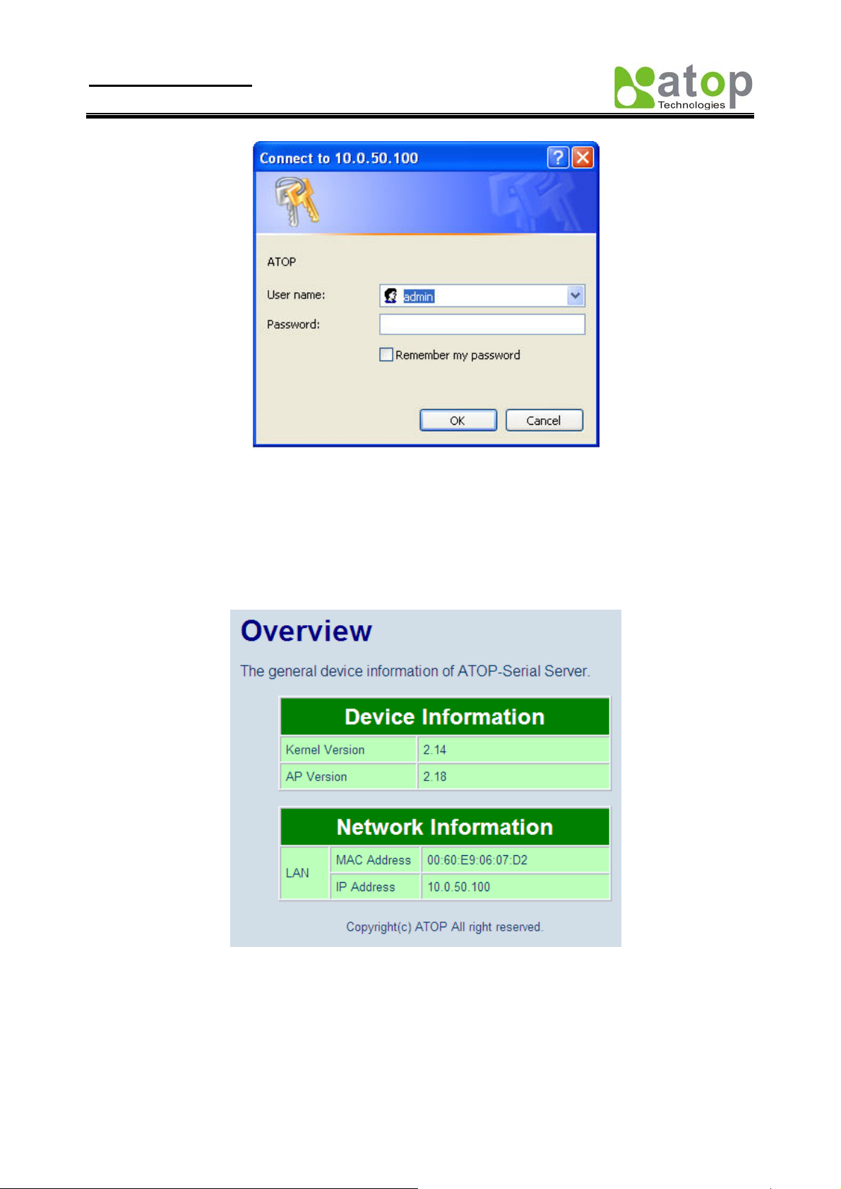
3.1. Login to System
Open one of the web browsers, ex. Microsoft IE or Firefox etc. Enter the IP address of SE8502-M12 on the URL.
Example:
The following authentication screen shall appear. Enter user name and password then click on “OK”. The default
user name is admin and password is null (leave it blank).
http://10.0.50.100 or http://user-device-IP
Copyright © 2010 Atop Technologies, Inc.
All rights reserved
11
Page 16
User manual Version 1.1
SE8502-M12 IP68 Serial Server
Fig 12. Authorization request for system security
The overview screen shall appear (Fig. 13)
.
3.2. General Information
This system overview window gives the general information on SE8502-M12, included Network, and Serial
information.
Fig 13. Overview for system information by Web Interface
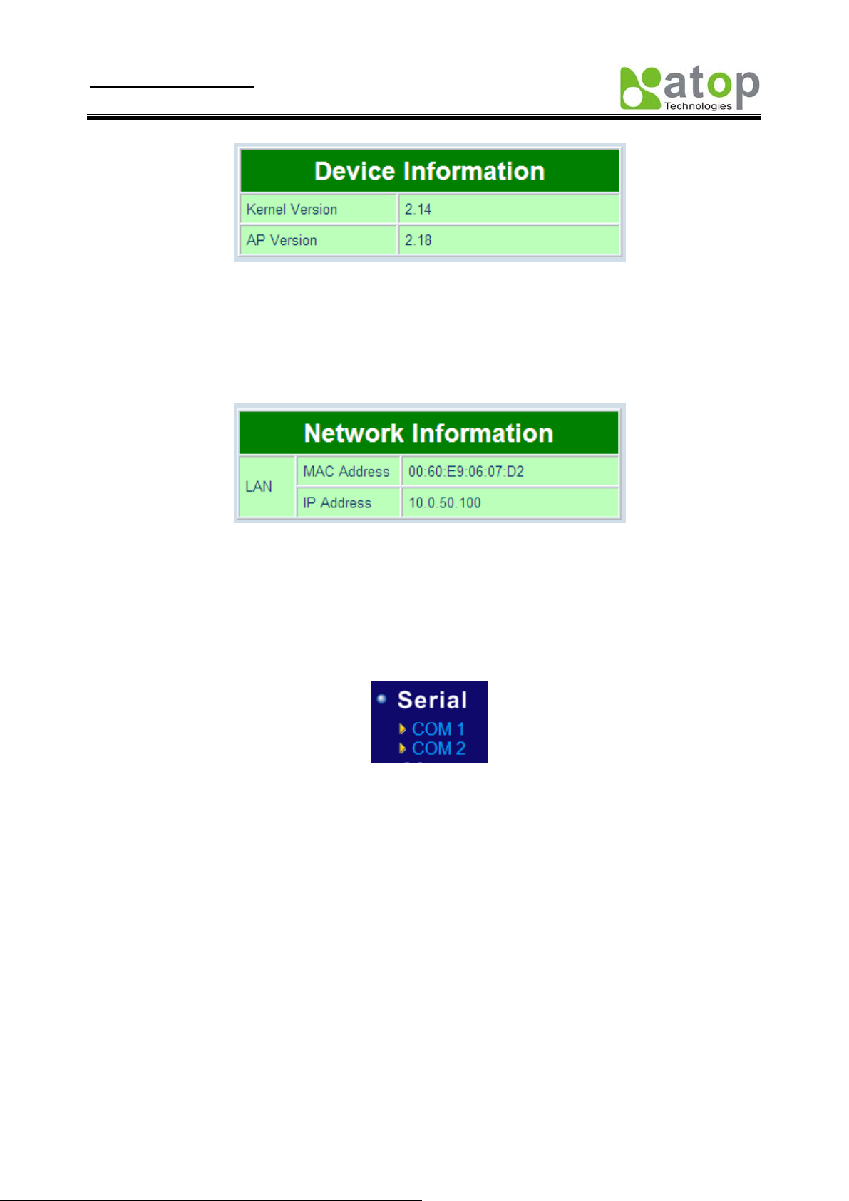
Device Information
SE8502-M12’s system information includes Kernel version and AP version. The information is read only and is
attributed from another setting page or system status
Copyright © 2010 Atop Technologies, Inc.
All rights reserved
12
Page 17
User manual Version 1.1
SE8502-M12 IP68 Serial Server
Fig 14. Device Information from Overview web page
Networking information
Networking information fields are displayed both ‘LAN & MAC Address information. The information provided
LAN MAC address.
Fig 15. Network Information from Overview web page
Serial Information
SE8502-M12 COM1 (COM2) information includes UART mode, link mode, baud rate, parity, data bits, stop bits,
flow control and link status. The COM1 (COM2) information is read only and is attributed from Serial settings of
COM1 or COM2 Port of SE8502-M12.
Fig 16. Serial Information from Serial setting
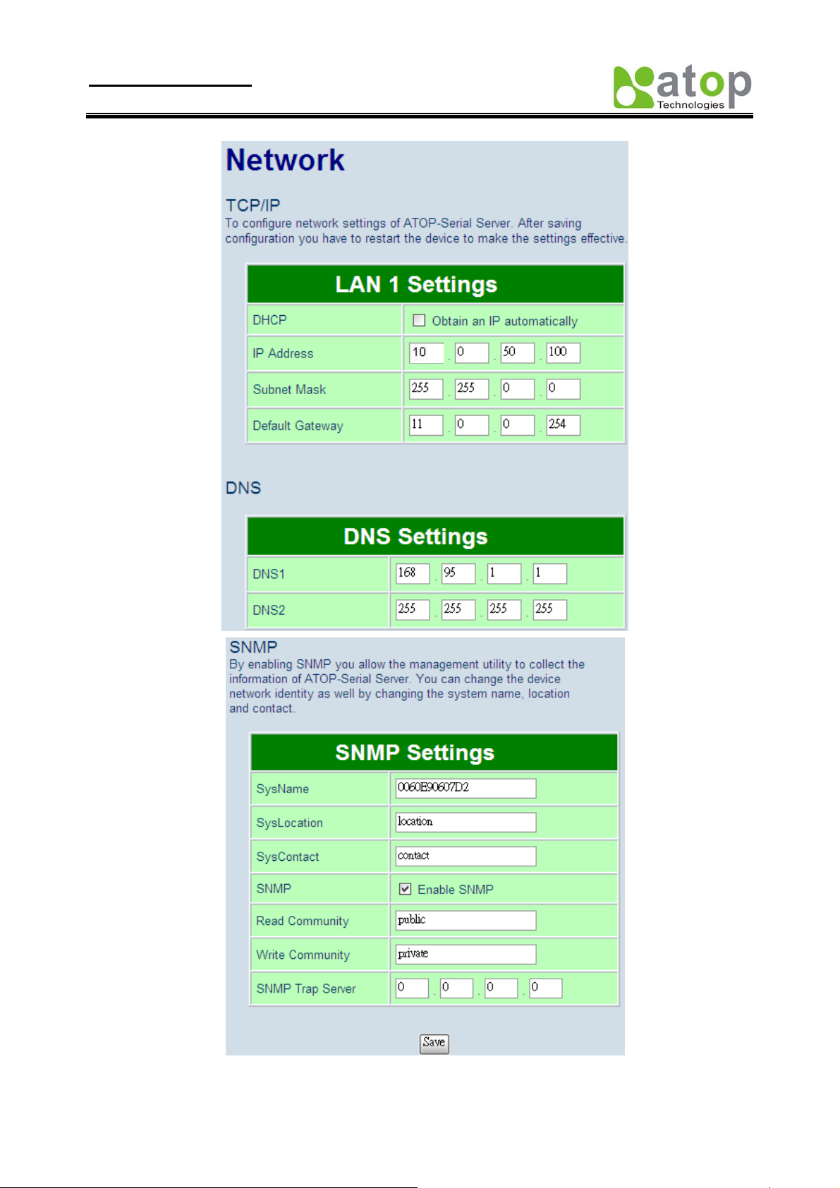
3.3. Network Configurations
There are four items allowed to change on Network page, included LAN, DNS and SNMP Information.
Copyright © 2010 Atop Technologies, Inc.
All rights reserved
13
Page 18
User manual Version 1.1
SE8502-M12 IP68 Serial Server
Fig 17. Network information by Web page
Copyright © 2010 Atop Technologies, Inc.
All rights reserved
14
Page 19
User manual Version 1.1
SE8502-M12 IP68 Serial Server
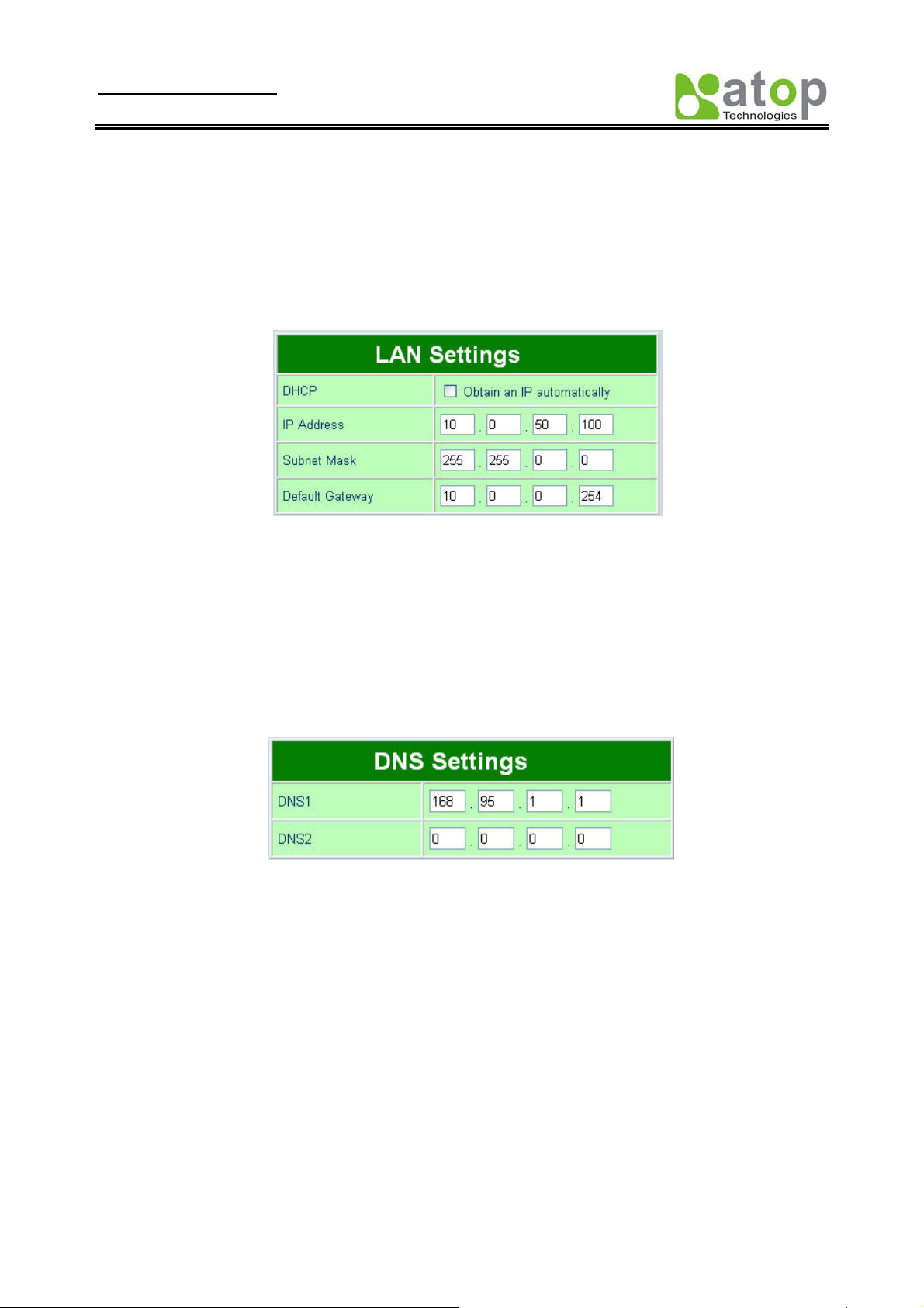
3.3.1. LAN Settings
Operation: [Network] Æ [LAN Setting]
Click on the “Network” link and the following screen shall appear. Fill in IP information on TCP/IP field.
Alternatively, click on DHCP to automatically obtain IP address, gateway and subnet mask information.
Fig 18. LAN Setting from Network web page
3.3.2. DNS Settings
Operation: [Network] Æ [DNS Settings]
Click on the “Network” link and the following screen shall appear. Fill in DNS information on DNS Settings field.
Alternatively, User can configure DNS by checking on “Obtain an IP automatically” field in LAN Settings or
WLAN Settings fields to automatically obtain DNS from DHCP server.
Fig 19. DNS Setting from Network web page
3.3.3. SNMP Settings
Operation: [Network] Æ [SNMP Settings]
Click on the “Network” link and the following screen shall appear. Check on “Enabling Settings” field. Fill in desired
SysName、 SysLocation、 SysContact in formation on SNMP Settings fields. The changes of SNMP Settings will
take effect only after the SE8502-M12 restarted.
Copyright © 2010 Atop Technologies, Inc.
All rights reserved
15
Page 20

User manual Version 1.1
SE8502-M12 IP68 Serial Server
Fig 20. SNMP Setting from Network web page
3.4. COM Port Configuration
Here User can configure Serial parameters, include alias, baud rate, parity, data bit and type of flow control defined
by user.
Fig 21. COM port Information Web Page
3.4.1. Link Mode Settings
Click on the “Serial” link and the Fig. 27 screen will appear.
Fill in Serial parameter information on Serial Settings field
Click on “Save Configuration” button to save the changes.
Copyright © 2010 Atop Technologies, Inc.
All rights reserved
16
Page 21

User manual Version 1.1
SE8502-M12 IP68 Serial Server
3.4.2. TCP Server Mode
TCP Server mode is default Link mode of Serial Settings, and it can wait for connecting requirement from remote
host PC which running “serial-to IP” utility or setting SE8502-M12s in tunneling mode. User has to configure
listening port to allow client establish connection to this server. Default port number of SE8502-M12 is 4660.
IP filtering function is a simple ACL (Access Control List). It can be disabled by setting FILTER_IP to “0.0.0.0”.
User can configure one or group IP for source IP. If IP filter is enabled, only source IP assigned can be connected to
SE8502-M12
Fig 22. TCP Server in Link mode
Note: Enable Virtual COM mode if the remote site PC’s “Serial to IP” tool is installed
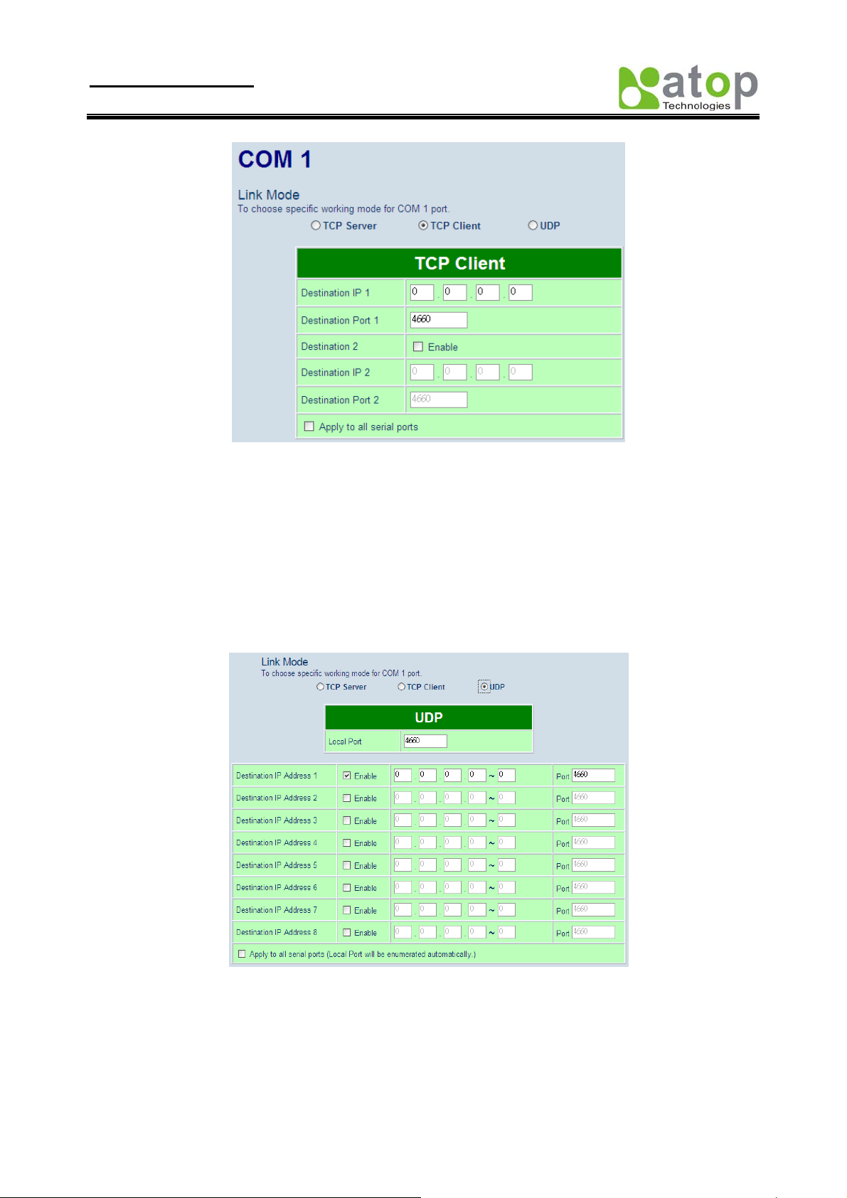
3.4.3. TCP Client Mode
User may enter destination IP & port (default: 4660) to establish connection of counter-pair (remote) host (For
example, another SE8502-M12, or PC for data-collection). SE8502-M12 can support two destination hosts
simultaneously.
Copyright © 2010 Atop Technologies, Inc.
All rights reserved
17
Page 22
User manual Version 1.1
SE8502-M12 IP68 Serial Server
Fig 23. TCP Client in Link mode
3.4.4. UDP Mode
SE8502-M12 can be configured in a UDP mode to establish connection using Unicast or Multicast data from the
serial device to one or multiple host computers. Vice versa is also true. For example, the original RS-422/ RS485 bus
can be transferred and extended connected distance by SE8502-M12s.
The destination IP is assigned by single IP or group IPs, The configuration is limited by the Local Listening Port. For
example, on SE8502-M12 listening port is 4660 which receive data sending from the host computers. SE8502-M12
can support up to 8-group IPs for UDP connection, if users neede d.
Fig 24. UDP protocol in Link mode
Note: In this phase, UDP mode does not support Virtual COM mode.
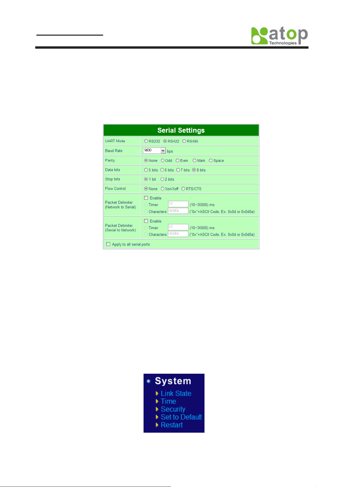
3.4.5. Serial Settings
This filed can be configured with serial parameters for SE8502-M12. Here User can configure Serial parameters,
include UART Mode, baud rate, parity, data bit and type of flow control.
Copyright © 2010 Atop Technologies, Inc.
All rights reserved
18
Page 23
User manual Version 1.1
SE8502-M12 IP68 Serial Server
Configure UART Mode: RS-232 or RS-485 or RS-422
Baud rate: 110/150/300/600/1200/2400/4800/9600/19200/38400/57600/115200/230400/460800/921600
Parity: None or Odd or Even or Mark or Space
Data bits: 5, 6, 7, 8 bits
Stop bits: 1 or 2
Flow control: None or Xon/Xoff or Hard w are (RTS/CTS).
Fig 25. Serial Communication Settings from Web Page
3.4.6. Delimiter Settings
Packet delimiter
Packet delimiter is a way of controlling the number of packets in a serial communication. It is designed to keep
packets in track. SE8502-M12 provides two ways in parameter settin g: (1) Packet delimiter by timer and (2) packet
delimiter by Character pattern. By default, packet delimiter timer is 1 ms. the range of packet delimiter timer is 1 to
30,000 msec. For Character pattern terminator, if “character pattern is selected and a data stream ended with “0x0a04”,
then the entire data buffer of the serial device is transmitted.
User can also choose character pattern as the packet delimiter indicated.
3.5. Configure System
There are five subsystems for system settings, included Time, WLAN Region, Security, Set to default and Restart.
Fig 26. Subsystem menu of system settings Web Interface
Copyright © 2010 Atop Technologies, Inc.
All rights reserved
19
Page 24

User manual Version 1.1
SE8502-M12 IP68 Serial Server
3.5.1. Configure Time by NTP Service
Operation: SystemÆTime
User can set date and time manually by fill in “Set Date and Time manually” field. User can also configure NTP
Server to obtain Network time automatically.
Fig 27. Time service settings from System web page
3.5.2. Security (change the Password)
Operation: System->Security
Click on the “Security” link and the following screen shall appear (Fig. 28).
Enter the old password on “Old Password” field then enter th e new password on “New Password” and the “Verified
Password” fields, and then click on “Save Configuration” to update the password. The maximum is 8 characters.
Copyright © 2010 Atop Technologies, Inc.
All rights reserved
20
Page 25

User manual Version 1.1
SE8502-M12 IP68 Serial Server
Note: User may press the default reset key to reset password to the default value(blank)
Fig 28. Change password from System Security Page
3.5.3. Restoring Factory Default Configurations
Operation: SystemÆ Set to Default
User can click on “set to default and restart” button to restore SE8502-M12’s settings to factory default (Fig.
29).
Fig 29. Set all parameters to factory default by Web Interface
3.5.4. Restart System
Operation: SystemÆ Restart
The changes of networking parameters will take effect only after the SE8502-M12 is restarted. User can restart
the SE8502-M12 manually by click on Restart button on the restart menu web page (Fig 30).
Fig 30. Restart system by Web
Copyright © 2010 Atop Technologies, Inc.
All rights reserved
21
Page 26

User manual Version 1.1
SE8502-M12 IP68 Serial Server
4. Telnet Configuration
User can also use Telnet utility to change SE8502-M12 configuration settings.
Open Ms-DOS command prompt window or other telnet tools
Enter the “IP address” of the SE8502-M12 (For example, Telnet 10.0.50.100). The system then prompts for
username and password, the default username is “admin” and the default password is null (blank).
Fig 31. Login into System by Telnet
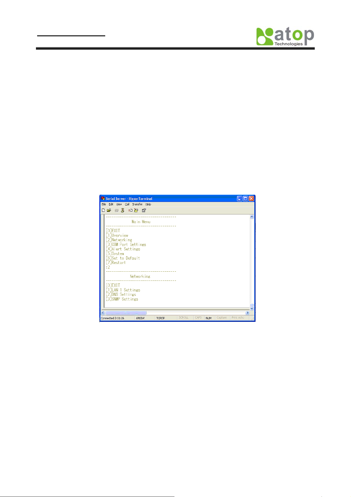
Then the following main menu shall appear
Fig 32. Overview information by telnet
If the SE8502-M12 does not receive any command within 1 minute, Telnet will be terminated
automatically.
The changes of networking parameters will take effect only after the SE8502-M12 is restarted.
Copyright © 2010 Atop Technologies, Inc.
All rights reserved
22
Page 27

User manual Version 1.1
SE8502-M12 IP68 Serial Server
4.1. General Information
Operation: [Main]Æ[1 Overview]
Select “1” from “Input choice (0~6) and enter:” to enter “overview page.
This system overview window gives the general information on LAN IP, MAC address, SNMP information, kernel
and AP version, and the connection status of the SE8502-M12 (Fig. 39).
The following overview information shall appear.
Device Information:
Kernel Version: [Read Only, Generated by system]
AP Version: [Read Only, Generated by system]
Ethernet Information:
MAC: [Read Only]
IP: [Allows for changes in Network Page]
Fig 33. System Information from Overview
DNS Information:
DNS1: [IP address of 1
DNS2: [IP address of 2
st
DNS Server, Allows for changes in Auto IP of Networking Page]
nd
DNS Server, Allows for changes in Auto IP of Networking Page]
SNMP Information:
SNMP Status: Enable [or Disable, Allows for changes in Networking Page]
SysName: [Allows for changes in Networking Page]
SysLocation: [Allows for changes in Networking Page]
SysContact: Allows for changes in Networking Page]
Copyright © 2010 Atop Technologies, Inc.
All rights reserved
23
Page 28
User manual Version 1.1
SE8502-M12 IP68 Serial Server
Serial Information:
UART mode RS485/RS232/RS422
Link Mode: TCP Server [or TCP Client/UDP Mode, Allows for changes in Serial Page]
Baud rate: 110/150/300/600/1200/2400/4800/9600/19200/38400/57600/115200/230400/460800/9216 00
Parity: None [or Even/Odd/Space/Mark...Allows for changes in Serial Page]
Data bits: 5, 6, 7, 8 bits
Stop bits 1 bit or 2 bits
Flow Control None, Xon/Xoff, RTS/CTS
4.2. Networking Configuration
Operation: [Main]Æ[2 Networking]:
Select “2” on “Input choice (0~6) and enter:” to enter Networking settings page.
Fig 34. Networking Settings by Telnet
Note: Press “0” key to return to the previous menu
This section allows for changes in IP address, subnet mask, gateway IP address and SNMP information. Please
note that setting changes will not take effect until the SE8502-M12 is restarted.
Copyright © 2010 Atop Technologies, Inc.
All rights reserved
24
Page 29

User manual Version 1.1
SE8502-M12 IP68 Serial Server
4.2.1. LAN Settings
Operation: [Main]Æ[2 Networking]Æ[1 LAN Settings]
Select “1” from “Input choice (0~3) and enter on Networking page:” to enter LAN Settings page. The MAC
address, IP address, subnet mask, gateway address, and IP mode information will be shown (Fig. 42). User also
can set IP, Netmask, Gateway, and IP mode of LAN interfaces by enter the corresponding menus and values. For
example, enter 1 for setting the IP address on LAN interface.
Fig 35. LAN Settings by Telnet
4.2.2. DNS Settings
Operation: [Main]Æ[2 Networking]Æ[2 DNS Settings]
Select “2” from “Input choice (0~3) and enter on Networking page:” to enter DNS Settings page.
Fill in the DNS information DNS1 or DNS2 or both according to user DNS server (Fig. 43).
Fig 36. DNS Settings by Telnet
Copyright © 2010 Atop Technologies, Inc.
All rights reserved
25
Page 30

User manual Version 1.1
SE8502-M12 IP68 Serial Server
4.2.3. SNMP Settings
Operation: [Main]Æ[2 Networking]Æ[3 SNMP Settings]
Select “3” from “Input choice (0~3) and enter on Networking page:” to enter SNMP Settings page. User can
enable/disable SNMP, and set network identification information on SNMP Settings page. The changes will not
become effective until SE8502-M12 is restarted
SE8502-M12 basically supports get/set SNMP parameters, these are SysName (System Name), SysLocation (System
Location) and SysContact (System Contact). These fields will response and supply basic system information from
standard SNMP query. User can set the SNMP system parameters by enter the corresponding menus and values. For
example, enter 2 for changing the SysName then enter the desired name.
Fig 37. SNMP Settings by Telnet
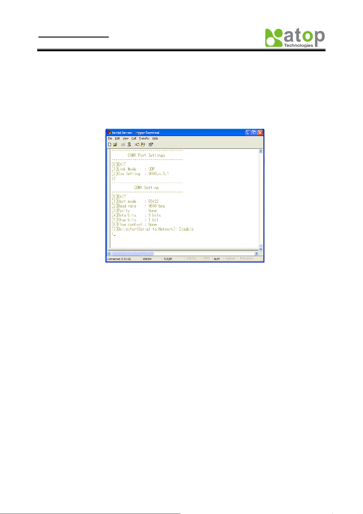
4.3. COM Port Configuration
User can configure serial parameters, include COM1(COM2) operation mode, port parameters, enable or disable
serial buffer’s data and packet delimiter.
Copyright © 2010 Atop Technologies, Inc.
All rights reserved
26
Page 31

User manual Version 1.1
SE8502-M12 IP68 Serial Server
Fig 38. Select COM Port from Serial Settings by Telnet
Fig 39. The COM1 Setting page
4.3.1. TCP Server Mode for Link Mode
Operation: [Main] Æ [4 Serial Settings] Æ [1 Link mode] Æ [1 TCP Server]
TCP Server mode is default setting for Link mode of serial settings of SE8502-M12, and it can be configured to wait
for the host computers to establish a connection with the serial device through SE8502-M12. SE8502-M12 needs to be
configure the listening port to waiting for host connection, Default Port number of SE8502-M12 is 4660 (4661) and it
is associated with the serial port COM1 (COM2). After the connection is established, data can flow in both directions.
SE8502-M12 can wait for connection requested from remote PC which installed “serial-to IP” tool or counter-pair
SE8502-M12 in tunneling mode. After the application program being con nected to the TCP port 4660 (4661) on the
SE8502-M12, data of user application program are transmitted transparently to serial devices through SE8502-M12
and vice versa.
User enters 1 at COM1 (COM2) Settings page and enters 1 for the TCP Server mode. To enable the remote client
which install “serial-to IP” to connect to SE8502-M12, user has to enable the Virtual COM and Set up the
designated port number.
IP filtering menu is a simple ACL (Access Control List). It can be disabled by setting FILTER_IP to “0.0.0.0”. User
can configure one or group IPs for source IP in IP filtering. If IP filtering is enabled, only source IP assigned can
connect to SE8502-M12.
Copyright © 2010 Atop Technologies, Inc.
All rights reserved
27
Page 32

User manual Version 1.1
SE8502-M12 IP68 Serial Server
Fig 40. TCP Server mode in link mode
Note: Enable Virtual COM mode if the remote site PC’s “Serial to IP” tool is installed.
4.3.2. TCP Client for Link Mode
Operation: [Main] Æ [4 Serial Settings] Æ [1 Link mode] Æ [2 TCP Client]
User can configure SE8502-M12 to work in TCP Client mode. On destination IP & port (default:
COM1:4660/COM2:4661), Enter the desired destination IP and port (Server IP and port) that SE8502-M12 want to
connect to (For example, another SE8502-M12, or PC for data-collection). The SE8502-M12 can support two
destination host computers simultaneously. Fig. 60 is the TCP Client page.
4.3.3. UDP for Link Mode
Fig 41. TCP Client mode in link mode
Copyright © 2010 Atop Technologies, Inc.
All rights reserved
28
Page 33
User manual Version 1.1
SE8502-M12 IP68 Serial Server
Operation: [Main] Æ [4 Serial Settings] Æ [1 Link mode] Æ [3 UDP]
SE8502-M12 can be configured to work in UDP mode to establish connection using Unicast or Multicast protocol.
Data can be transmitted from one or multiple serial devices to/from one or multiple host PCs and vice versa. For
example, the original RS-422/ RS485 bus data is transferred over the extended conn ected distance by SE8502-M12s,
The destination IP is assigned by single IP or group IPs, The configuration is limited by the Local Listening Port,
default 4660 and 4661 on the COM1 and COM2 of SE8502-M12.
SE8502-M12 can support up to 8-group IPs for UDP connection, if users needed.
Fig 42. UDP mode in link mode
Note: In this phase, UDP mode does not support Virtual COM mode.
4.3.4. Serial Settings
Operation:
[Main] Æ [4 Serial Settings] Æ [2 Baud rate]/ [3 Parity]/[4 Data bits]/ [5 Stop bits]/ [6 Flow control]
User can configure baud rate、data bits, parity、stop bit and type of flow control.
Copyright © 2010 Atop Technologies, Inc.
All rights reserved
29
Page 34

User manual Version 1.1
SE8502-M12 IP68 Serial Server
Note: The photo-couple isolation one, SE8502-M12, only supported max 230Kbps baud rate.
Fig 43. Serial Settings by Telnet
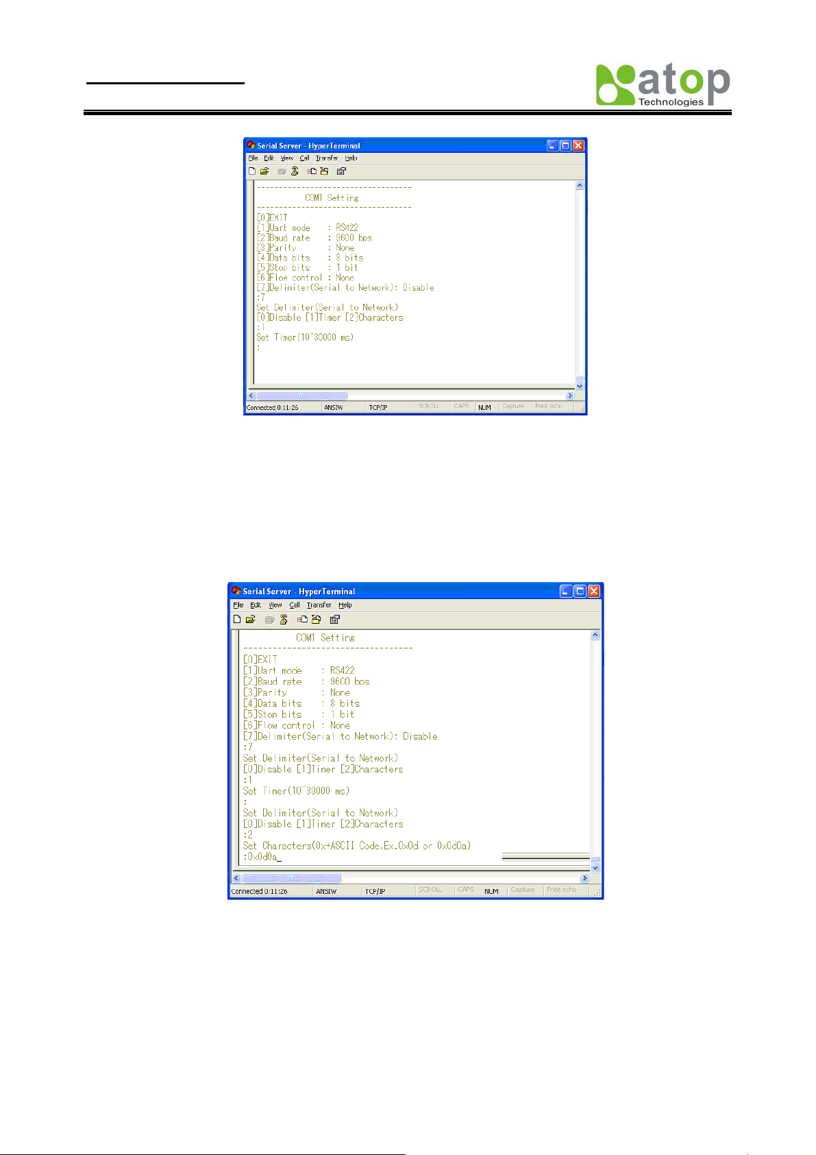
4.3.5. Packet Delimiter
[Main] Æ [4 Serial Settings] Æ [8 Delimiter (Network to Serial)]/ [9 Delimiter (Serial to Network)]
Packet delimiter is a way of controlling the number of packets in a serial communication. It is designed to keep
packets in track. SE8502-M12 provides two ways in packet deli miter parameter setting: (1) Packet delimiter by timer
and (2) Packet delimiter by character. By default, packet delimiter timer is 10 ms. The ranges of packet delimiter
timer is 10 to 30,000 ms, If “character pattern’ is selected, for a data stream ended with “0x0d0a”, then the entire data
buffer of the serial device is transmitted.
User can change packet delimiter timer by following the steps below.
Configure Network Delimiter using Timer
[Main]Æ[4 Serial Settings]Æ [8 Delimiter (Network to Serial)]/ [9 Delimiter (Serial to Network)]
Æ[1 Timer]
User can choose packet delimiter timer’s value as the packet delimiter indicated in Fig. 63 below
Copyright © 2010 Atop Technologies, Inc.
All rights reserved
30
Page 35
User manual Version 1.1
SE8502-M12 IP68 Serial Server
Fig 44. Configure Network Delimiter using Timer
Configure Network Delimiter using Characters
[Main]Æ[4 Serial Settings]Æ [8 Delimiter (Network to Serial)]/ [9 Delimiter (Serial to Network)]
Æ[2 Characters]
User can choose packet delimiter character pattern as the packet delimiter indicated in the Fig. 45 below:
Fig 45. Configure Network Delimiter using Characters
4.4. Security Configuration
Operation: [Main] Æ [5 Security]
User can change password of SE8502-M12 with this menu.
Copyright © 2010 Atop Technologies, Inc.
All rights reserved
31
Page 36

User manual Version 1.1
SE8502-M12 IP68 Serial Server
Fig 46. Security settings by Telnet
4.4.1. Change the Password
Operation: [Main] Æ [5 Security]Æ [1 Change Password]
Enter desired password on “New password” fields.
Fig 47. Changing the Password by Telnet
Note: User may press the reset key on the product to reset to default password (blank).
Copyright © 2010 Atop Technologies, Inc.
All rights reserved
32
Page 37
User manual Version 1.1
SE8502-M12 IP68 Serial Server
APPENDIX A. USING VIRTUAL COM
Virtual COM driver mode for windows converts COM port data (RS232) to IP data to control the RS-232C port on a
SE8502-M12 over the IP network. By creating Virtual COM ports on the PC, Virtual COM redirects the
communications from the Virtual COM ports to an IP address and port number on a SE8502-M12 which connected to
the serial devices. The following figure is Virtual COM connection diagram.
Fig 48. Setup of a Virtual COM driver
A.1 Pre-installation Requirements
Please check the operating system on your PC complied with the following requirements:
Processor: Intel-compatible, Pentium class
Operation system: Windows Server 2003, Windows XP, Windows 2000, Windows NT 4.0 SP5 or later,
Windows Me, Windows 98, Windows 95, Microsoft NT/2000 Terminal Server, Citrix Meta Frame
Windows Installer 2.0
Network: Microsoft TCP/IP networking software
A.2 Applying to the SE8502-M12
Limitation
Virtual COM driver provides user to select up to 4096 COM ports as Virtual COM ports in a SerialManager Utility
PC. User can select them from a list of COM ports, which is from COM1 up to COM4096.
Installation
Make sure you have turned off all anti-virus software before beginning the installation. Run Vcom.exe program
included in the CD to install Virtual COM for your operating system.
In the end of the installation, please select one or two COM ports to become the Virtual COM ports.
Uninstalling
From Windows Start menu, select Setting\ Control Panel\ Add/Remove Programs.
Select Serial IP for in the list of installed software.
Click the Add/Remove button to remove the program, or From Windows Start menu select Programs, Serial
IP click Uninstall Serial IP to remove the program.
Copyright © 2010 Atop Technologies, Inc.
All rights reserved
33
Page 38

User manual Version 1.1
SE8502-M12 IP68 Serial Server
A.3 Virtual COM Communication
Enable Virtual COM on SE8502-M12 by web interface
From web browser access to SE8502-M12 by typing its IP address, click on “Serial” link to access Serial page, on the
top half of the page click on “TCP Server” and enable Virtual COM by putting a check in front of the “Enable”
checkbox, then type in the local port number in the “Local Port” field as indicated in the following screen.
Fig 49. Enable Virtual COM Mode by Web page
Enable Virtual COM on SE8502-M12 by Telnet
User may also enable Virtual COM through telnet by setting Serial as a TCP server, and enter the local port number for
Serial, then enable virtual COM as shown in the following procedure:
Login SE8502-M12 via Telnet
Fig 50. Login into SE8502-M12 by Telnet or Console
Select serial setting for TCP server/Client, and enabling Virtual COM mode
Copyright © 2010 Atop Technologies, Inc.
All rights reserved
34
Page 39

User manual Version 1.1
SE8502-M12 IP68 Serial Server
Fig 51. Enable Virtual COM mode by Telnet
Running Serial to IP for program on PC
On Window Start Menu, go to\program\Serial/IP\Control panel\, The “Serial to IP for Control Panel” window shall
appear. Then select the serial port.
Fig 52. Detail setting from Serial/IP
On the right of the panel is a sample for COM 4 settings. On the left is the list of the COM ports that have been
selected (on Select Ports window) for use by the Vir tua l C OM Redirector. Change the list by clicking the Select
Ports button.
Each COM port has its own settings. When click on a COM port, the Control Panel changes to reflect that the
selected port.
Note: COM port changes become effective immediately.
Configure Virtual COM Ports
Serial/IP COM port can be changed as follows:
Copyright © 2010 Atop Technologies, Inc.
All rights reserved
35
Page 40
User manual Version 1.1
SE8502-M12 IP68 Serial Server
Select a COM port on the list.
On IP Address of Server, enter SE8502-M12 IP address.
On Port Number, enter the TCP port number of the SE8502-M12.
On Server Credentials, the default is No Login Required. If the SE8502-M12 does require login by the
Virtual COM Redirector, the Virtual COM Redirector must provide a username and/or password every time
an application tries to access the SE8502-M12.
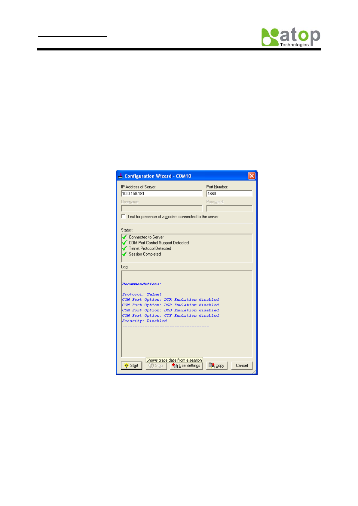
Click the Configuration Wizard button and then click the Start button that shall appear on the wizard
window. This step verifies that the Virtual COM Redirector communicates with the SE8502-M12. If Log
display does not show errors, click Use Settings, return to the Control Panel
Settings on the Connection Protocol must match the TCP/IP protocol supported by the SE8502-M12. The
Configuration Wizard is capable of determining the correct settings.
On COM Port Options, the settings must match the COM port behavior expected by the PC
application. The Configuration Wizard will recommend such settings.
Fig 53. Configuration Wizard from Serial to IP tool
Copyright © 2010 Atop Technologies, Inc.
All rights reserved
36
Page 41
User manual Version 1.1
SE8502-M12 IP68 Serial Server
Appendix B. Configuration Utility
B1. SerialManager utility Introduction
SerialManager utility, developed by ATOP, is a special tool for device management and configuration, and can
realize the daily management on various ATOP network devices for address search, device positioning, parameter
configuring, firmware downloading and so on.
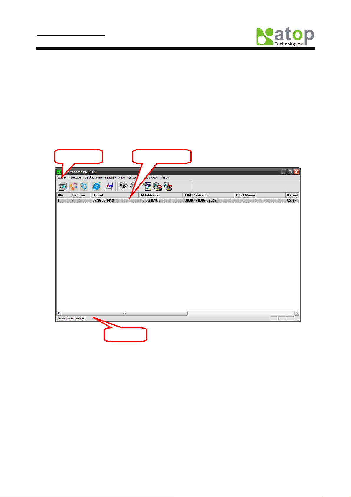
B2. Interface
The operating interface of the SerialManager utility showed as below:
Main menu Device details
Status bar
B3. Functions
B3.1 Device Search
This function is applied to search devices in the n etwork. The user can use four ways to search devices. They are
search by broadcast, search by special IP addresses, search by special MAC addresses and rescanning devices by using
the current search way. The user can select his required search way by clicking the Search option on the main menu,
shown as below:
Copyright © 2010 Atop Technologies, Inc.
All rights reserved
37
Page 42

User manual Version 1.1
SE8502-M12 IP68 Serial Server
Or, select by clicking a button on the toolbar, as below:
Broadcast
Search
Rescan
B3.1.1 Broadcast Search
Once Broadcast Search is selected, a box will pop up as below:
Copyright © 2010 Atop Technologies, Inc.
All rights reserved
38
Page 43

User manual Version 1.1
SE8502-M12 IP68 Serial Server
The user may type in or select different broadcast address based on his/her own requirement.
B3.1.2 Search by IP address
Once Search by IP Address is selected, an interface will pop up as below:
Here user may have two options: Select an IP address to search or Search device in the range of IP address.
Copyright © 2010 Atop Technologies, Inc.
All rights reserved
39
Page 44
User manual Version 1.1
SE8502-M12 IP68 Serial Server
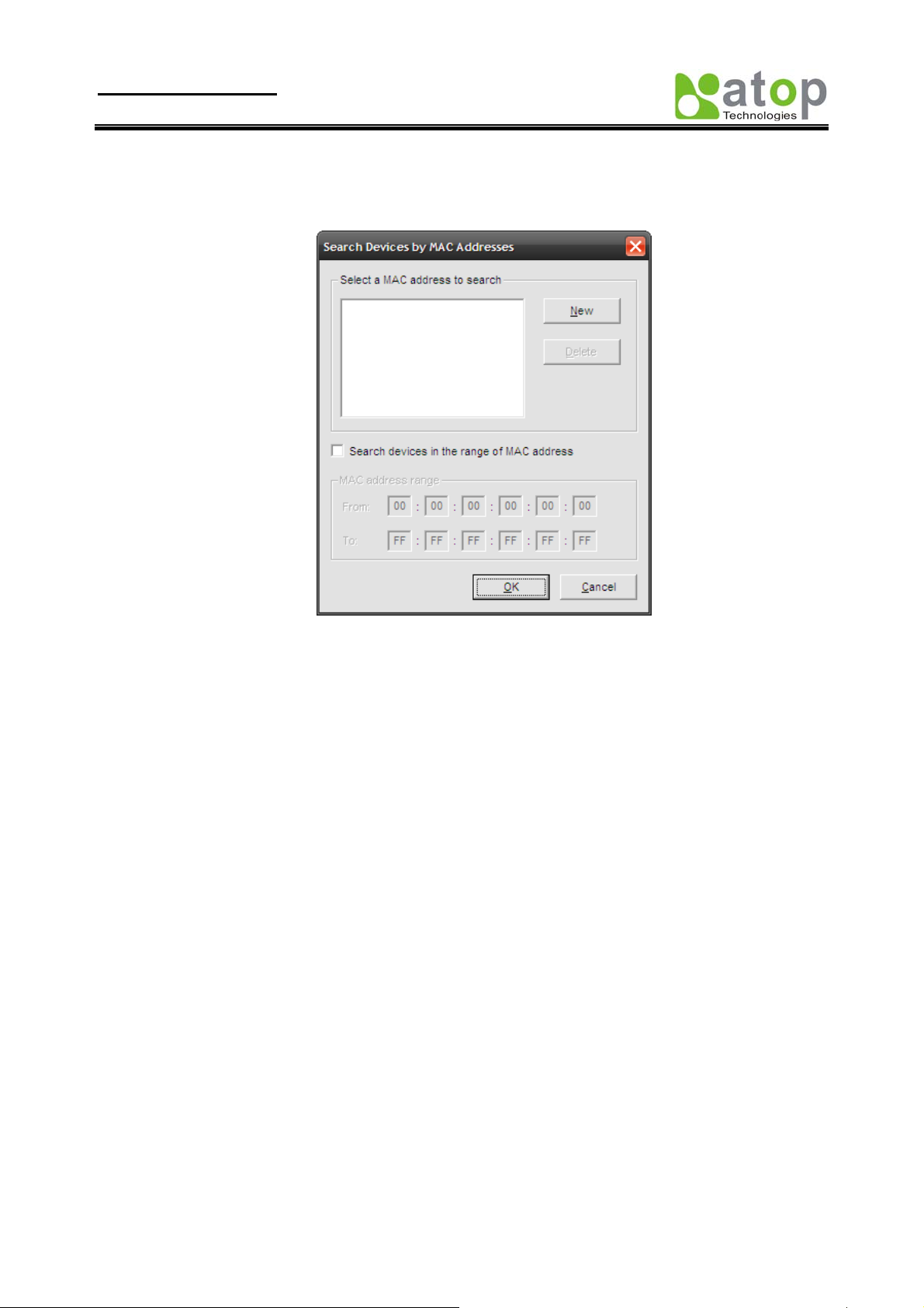
B3.1.3 Search by MAC Address
If Search by MAC Address is selected, another box will pop up as below:
Here the user may search in two ways: Search a MAC address to search or Search devices in the range of MAC
address
B3.1.4 Rescan
Once the user click the Rescan button on the toolbar, the SerialManager utility shall re-search devices by using the
current search way.
Copyright © 2010 Atop Technologies, Inc.
All rights reserved
40
Page 45
User manual Version 1.1
SE8502-M12 IP68 Serial Server
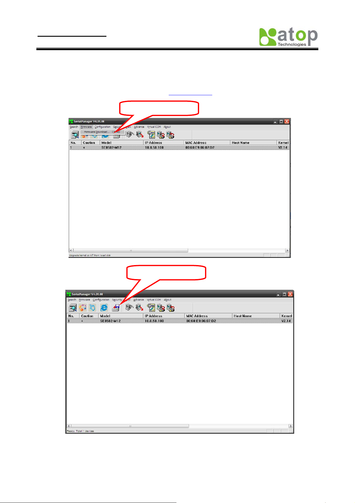
B3.2 Firmware Upgrade
This function is applied to downloading a firmware into a selected device.
Updated version of firmware can be downloaded from
Upgrade from disk
www.atop.com.tw.
Upgrade from disk
The user can enter the window for downloading b y firstly clicking a designated n etwork device, and th en selecting the
submenu option Upgrade from disk in the main menu option Firmware, or directly clicking the button Upgrade
from disk. And then the user can select and download the required firmware from the disk, as shown in the figure
Copyright © 2010 Atop Technologies, Inc.
All rights reserved
41
Page 46
User manual Version 1.1
SE8502-M12 IP68 Serial Server
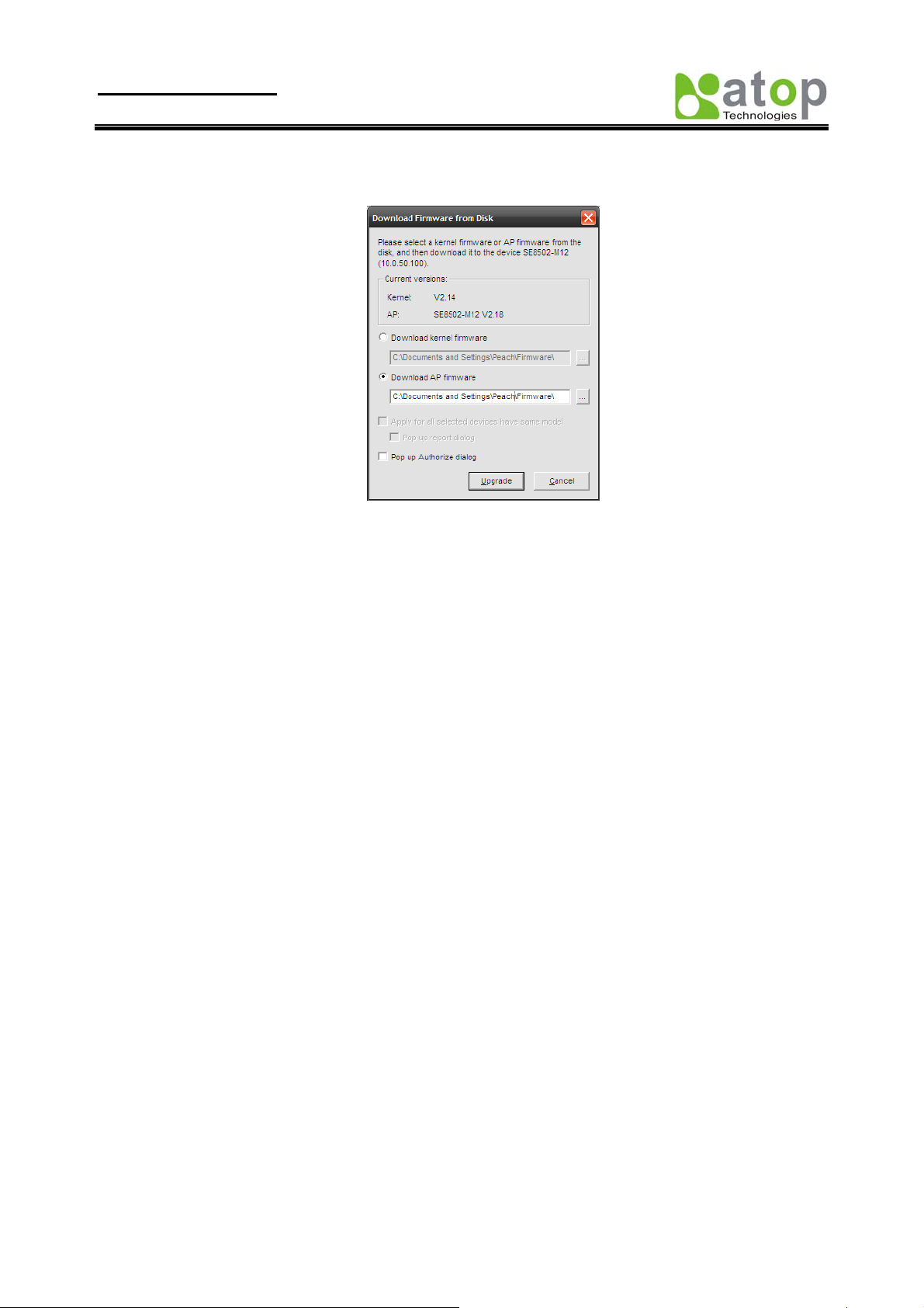
below:
The user can also select several same devices at one time, and realize the firmware updating for them by
selecting Apply for all selected devices have same model.
Note: Please always download AP firmware before downloading kernel firmware. The upgrade process
could take up more than three minutes. If your device disappears from SerialManager after upgrade,
please refer to Appendix C for recovery methoods.
B3.3 Security
This function is applied to the security protection for the network devices, so as to supply some necessary
protection to a device for configuration modifying, configuration leading-in and leading-out, and some other
important functions. Here three functions are mainly supplied, including: Login, Logout and Change
Password, shown as the figure below:
Copyright © 2010 Atop Technologies, Inc.
All rights reserved
42
Page 47
User manual Version 1.1
SE8502-M12 IP68 Serial Server
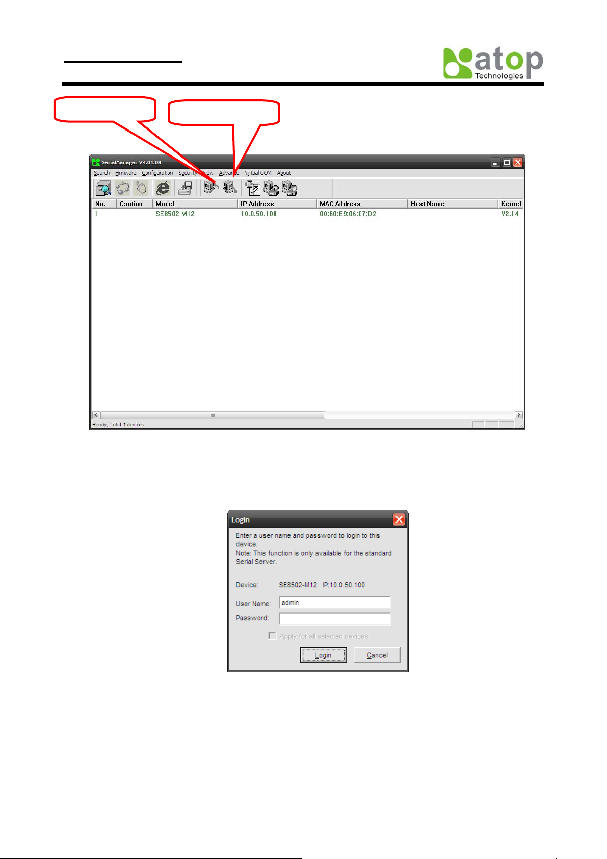
Login
Logout
B3.3.1 Login
This function is applied to the login to any network device, as some important devices can only be operated
after a successful login, shown as the figure below:
The user can also select several devices at one time, and log in them at the same time by selecting Apply
for all selected devices.
B3.3.2 Logout
This function is applied to the logout from any network device, as the user should always carry out a logout
after he/she has finished the operating action to any import ant device, shown as the figure below:
Copyright © 2010 Atop Technologies, Inc.
All rights reserved
43
Page 48

User manual Version 1.1
SE8502-M12 IP68 Serial Server
The user can also select several devices at one time, and log out them at the same time by selecting Apply
for all selected devices.
B3.3.3 Change Password
This function is applied to modifying the password for logging in any network device, but can only be
realized after a successful log-in, shown as the figu re below:
The user can also select several devices at one time, and modify their pins at the same time by selecting
Apply for all selected devices.
B3.4 Configuration
This function is applied to the configuring, import and export of work parameters for any network device,
and here are mainly supplied with: ‘Network …’, ‘COM Port…’, ‘Locate’, ‘Reset’, ‘Erase Flash’, ‘Import
Setting…’, ‘Export Setting…’, ‘Virtual COM…’, ‘Config by IE’ and ‘Options’, and some other application
functions. The user can carry out a configuration operating through
menu or by clicking the corresponded button on the toolbar, shown as the figure below:
Copyright © 2010 Atop Technologies, Inc.
All rights reserved
44
Page 49

User manual Version 1.1
SE8502-M12 IP68 Serial Server
Locate
Network … COM
Port …
Import
Setting
Export
Setting …
B3.4.1 Network …
The user can modify the IP address of any selected device, shown as the figure below:
B3.4.2 COM Port …
ATOP has developed various network products, and some of the ATOP devices are specially supplied to
some serial-port servers, while this function is applied to the configuration of COM port parameters.
Note: This function can be realized only after a successful login, shown as the figure below:
Copyright © 2010 Atop Technologies, Inc.
All rights reserved
45
Page 50

User manual Version 1.1
SE8502-M12 IP68 Serial Server
The user can also select several devices at one time, and carry out the configuration for them at the same
time by selecting Apply for all selected same model devices
Note:
1. COM tags: generated automatically according to the COM port number of the device. If a device has 4
COM port, there will be 4 tags: respectively COM1, COM2, COM3, COM4, and the like.
2. Connecting mode: it means the connecting mode between the serial-port server and other network
devices. Each COM corresponds to a connecting mode through which the transferring data will not be
interfered by that in another connection. The user can set each corresponded connecting mode and the
working parameter by clicking the button "Option", shown as the figure below:
TCP Server mode TCP Client mode
Copyright © 2010 Atop Technologies, Inc.
All rights reserved
46
Page 51

User manual Version 1.1
SE8502-M12 IP68 Serial Server
3. COM port property: it mainly represents the working parameter of the serial port setting, including:
serial-port working type, baud rate, data bit, stop bit, parity bit, data packet delimiter and flow control,
etc.
UDP mode
B3.4.3 Locate
The user can apply this function to locate a device when he knows it’s IP address, but doesn’t know its
position. If a device is selected, the device will appear with singing by which the user can locate the device
through the submenu option Locate or clicking the Locate button on the toolbar.
B3.4.4 Reset
The device should be restarted after a successful modification of parameter configuration. And the user can
carry out a restart through the submenu option Reset.
B3.4.5 Erase Flash
Some devices are supplied to the user with a certain capacity of Flash memory to save the user's data. And
the user can erase the Flash through the submenu option Erase Flash or clicking the Erase Flash button
on the toolbar when the memory capacity is to be used up or the history data are unnecessary to be saved.
B3.4.6 Import Setting …
If a network has a large number of devices which are used for a same purpose, it would be very
complicated to carry out the parameter configuration for each of the devices in the network one by one,
while the user can import the parameter information of a standard parameter file directly into all the devices
of the network through the submenu option Import setting … or clicking the Import setting … button on
the toolbar, thus the work proced ures can be largely reduced, shown as the figure below:
Copyright © 2010 Atop Technologies, Inc.
All rights reserved
47
Page 52

User manual Version 1.1
SE8502-M12 IP68 Serial Server
The user can also select several devices at one time, and lead the parameter information of a standard
parameter file into all the selected devices by selecting Apply for all selected devices hav e same model.
B3.4.7 Export Setting…
If a network has a large number of devices which are used for a same purpose, it would be very
complicated to carry out the parameter configuration for each of the devices in the network one by one,
while the user can save the parameter information of a standard device into a parameter file through the
submenu option Export setting… or clicking the Export setting… button on the toolbar, thus the
parameter information can be led in over again from this parameter file when the user is to carry out a
configuration for any other device, shown as the figure below:
Copyright © 2010 Atop Technologies, Inc.
All rights reserved
48
Page 53

User manual Version 1.1
SE8502-M12 IP68 Serial Server
The user can also select several devices at one time, and save the parameter information of these selected
devices into a designated parameter file by selecting "Save all the selected devices".
Copyright © 2010 Atop Technologies, Inc.
All rights reserved
49
Page 54

User manual Version 1.1
SE8502-M12 IP68 Serial Server
B3.4 Configuration
This function is applied to the configuring, import and export of work parameters for any network device, and here are
mainly supplied with: ‘Network …’, ‘COM Port…’, ‘Locate’, ‘Reset’, ‘Erase Flash’, ‘Import Setting…’, ‘Export
Setting…’, ‘Virtual COM…’, ‘Configure by IE’ and ‘Options’, and some other application functions. The user can
carry out a configuration operating through menu or by clicking the corresponded button on the toolbar, shown as the
figure below:
Network … Locate
A3.4.1 Network …
The user can modify the IP address of any selected device, shown as the figure below:
Copyright © 2010 Atop Technologies, Inc.
All rights reserved
50
Page 55

User manual Version 1.1
SE8502-M12 IP68 Serial Server
B3.4.3 Locate
The user can apply this function to locate a device when he knows it’s IP address, but doesn’t know its position. If a
device is selected, the device will appear with singing by which the user can locate the device through the submenu
option Locate or clicking the Locate button on the toolbar .
B3.4.4 Reboot
The device should be restarted after a successful modification of parameter configuration. And the user can carry out a
restart through the submenu option Reboot.
B3.4.5 Configure by IE
Some devices are supplied with build-in Web servers, and the user can carry out any parameter setting directly through
the submenu option Config by IE, shown as the figure below:
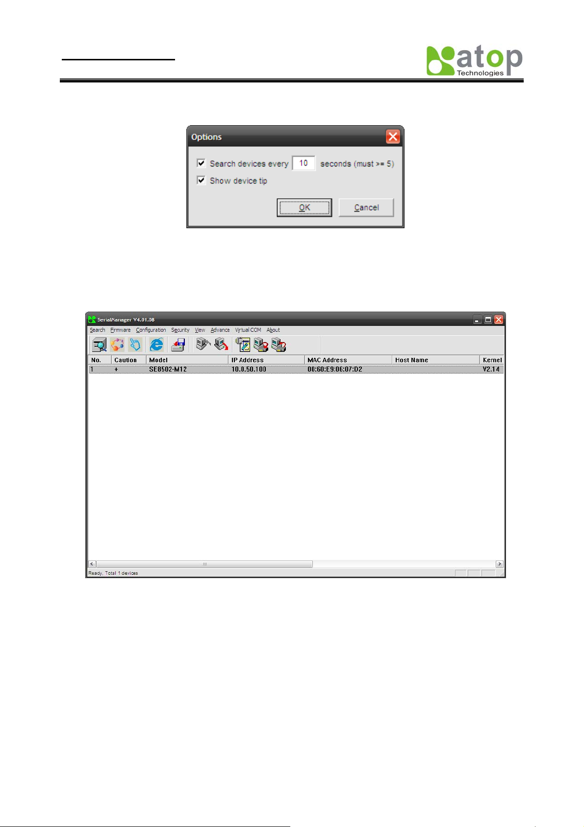
B3.4.6 Option
Copyright © 2010 Atop Technologies, Inc.
All rights reserved
51
Page 56
User manual Version 1.1
SE8502-M12 IP68 Serial Server
The option is mainly applied to setting some common work rules of SerialManager utility, such as: search for the time
interval of a network device, or whether to display any device indication and so on, shown as the figure below:
B3.5 View
The user can select a display mode of the network device according to his/her own requirement through the menu
option "View", such as: display in sequence of device module name, or display in sequence of IP address and so on,
shown as the figure below:
B3.6 Help
This function is mainly applied to displaying some help information of the SerialMan ager utility, shown as the figure
below:
Copyright © 2010 Atop Technologies, Inc.
All rights reserved
52
Page 57

User manual Version 1.1
SE8502-M12 IP68 Serial Server
Copyright © 2010 Atop Technologies, Inc.
All rights reserved
53
Page 58

User manual Version 1.1
SE8502-M12 IP68 Serial Server
Appendix C. Emergency System Recovery
If your device becomes inaccessible and SerialManager cannot find your device, please use the following procedure to
recover your device.
C1. System Recovery Procedures
System recovery is based on the TFTP Client embedded in the device. It can recover the device from a bad firmware
flash and other unknown reasons if the bootloader is still functioning properly. At boot time, the device will try to
connect to a TFTP Server and download valid kernel and AP to recover its Linux System.
Default Settings:
TFTP Server IP: 10.0.50.201
TFTP Server Subnet Mask: 255.255.0.0
Name of Kernel Image: se8502-ker.rom
Name of AP Image: se8502-ap.rom
Name of “Reset to Default” file: 0060E9XXXXXX.cmd
*Please obtain the two ROM images from the CD. File name of the reset file is the device’s MAC with cmd extension,
For example, 0060E90607D6.cmd.
Follow the upgrading procedures below for the latest firmware.
Obtain and setup a TFTP server on your PC. Make sure that the PC network settings of the PC is set
properly according to the default above.
Place kernel, AP, and the reset file in the root directory of the TFTP Server. For Solarwinds, it is usually
C:\TFTP-Root.
Power on the device. If the bootloader is still func tioning, you should see that the device requested files
from your TFTP Server. Please wait until the device shows up on the SerialManager. This process could take
five minutes or more.
Stop or Close your TFTP Server to prevent firmware recovery loop every time the device restart.
Tips : You can download free TFTP Servers from following locations:
Solarwinds TFTP Server
http://www.solarwinds.com/products/freetools/free_tftp_server.aspx
Please remember to Start the TFTP Server Service as illustrated in the following picture, default is Stop.
Copyright © 2010 Atop Technologies, Inc.
All rights reserved
54
Page 59

User manual Version 1.1
SE8502-M12 IP68 Serial Server
Fig 81. Solarwinds TFTP Server Configuration Window
Copyright © 2010 Atop Technologies, Inc.
All rights reserved
55
Page 60

User manual Version 1.1
SE8502-M12 IP68 Serial Server
Appendix C. SPECIFICATION
Hardware Specifications
Specifications
Ethernet
Compliance IEEE802.3
Network Interface 10/100 Mbps Fast Ethernet Tx+
Port One port
Connector M12
Auto MDI/MDI-X Yes
Link Mode
TCP Server Up to 4 connections or Virtual COM mode
TCP Client Up to 2 destination or Virtual COM mode
UDP Up to 8 destination
Transmission
Rate
10/100M Auto-detection
Serial
Interface RS-232/RS-422/RS-485 Software selectable
Ports 2 Ports
Baud Rate
Parity None, Odd, Even, Mark, Space
Data bits 5, 6, 7, 8
Stop Bit 1,2
Flow Control None, Software:Xon/Xoff,Hardware:RTS/CTS
Protection 15KV ESD
Connector M12
Power
Input 9-48DCV, 0.4A max
consumption Max. 3.6W
LED
Indicator COM, LAN, RUN
Approval
EMC CE Class A, FCC Class A
Protection IP68 Rated IEC/EN60529
Vibration IEC60068-2-64
Shock IEC60068-2-27
Free-fall IEC60068-2-32(ISTA Test Procedure 2A)
1 10bps~230kbps(Isolation)
110bps~921.6kbps(non-isolation)
Environment
Operating
-40℃~75℃(-40°F ~167°F)
Copyright © 2010 Atop Technologies, Inc.
All rights reserved
56
Page 61

User manual Version 1.1
SE8502-M12 IP68 Serial Server
Storage
Humidity 5%~95% Non-condensing
Dimension
(WxHxD) 79mm x 35mm x 144mm
Physical
Weight 700g
Installation Field-style mounting
Warranty 5 years
MTBF
Preceding TBD
Sofetware
Configuration Web Page / Telnet / Serial console / Windows Utility
Virtual COM Windows & Linux port redirection software
Support Protocol
SE8502-M12 IP68 Rated 2-Port Serial Device Server
SE8502-M12-Sis-M12 IP68 Rated 2-Port Serial Device Serve r, 2KV Isolation
-40℃~85℃(-40°F ~185°F)
ICMP, TCP/IP, UDP, DHCP Client, NTP, DNS, SNMP, HTTP, Telnet,
SMTP
Ordering Information
Copyright © 2010 Atop Technologies, Inc.
All rights reserved
57
Page 62

User manual Version 1.1
SE8502-M12 IP68 Serial Server
Warranty Policy
Warranty Conditions
Products supplied by Atop Technologies are covered in this warranty for sub-standard performance or defective
workmanship. The warranty i s not, however, extended to goods damaged in the following circumstances:
(a) Excessive forces or impacts
(b) War or an Act of God: wind storm, fire , flood, el ectri c shock, earthquak e
(c) Use of unqualified power supply, connectors, or maintenance procedure
(d) Replacement with unauthoriz ed parts
RMA and Shipping Costs Reimbursement
Customers shall always obtain an authorized "RMA" number from Atop before shipping the goods to be repaired to
Atop. When in normal use, a sold product shall be replaced with a new one within 3 months after purchase. The
shipping cost from the customer to Atop will be reim bursed by Atop .
After 3 months and still within the warranty period, it is up to Atop whether to replace the unit with a new one;
normally, as long as a product is under warranty, all parts and labor are free of charge to the customers.
After the warranty period, the customer shall cover the cost for parts and labor.Three months after purchase, the
shipping cost from the customer to Atop will not be r e i mbursed, but the shipping cost from Atop to the customer will
be paid by Atop.
Limited Liability
Atop shall not be held responsible for any conseque nti al l osses fr om using Atop’s product.
Warranty Period
Industrial Serial to Ethernet Switch: 5 years
*Notes: Warranty coverage for Accessories such as power adapters and high-gain antenna is one year.
ATOP Customer Services and Supports
1. Please contact your local dealers or Atop Technical Support Center at the following numbers.
y +886-3-550-8137 (Atop Taiwan)
y +86-21-6495-6232 (Atop China)
2. Please report the defected problems via Atop’s Web site or E-mail account
Web Site:www.atop.com.tw, e-mail: service@atop.com.tw
Web Site:www.atop.com.cn, e-mail: service@atop.com.cn
Copyright © 2010 Atop Technologies, Inc.
All rights reserved
58
 Loading...