

Page 1

ABLELink®
SE5002 Ethernet Serial Server
Quick Start Guide
Version 1.3
Updated on 2008/02/29
Tel: 886-3-5508137
Fax: 886-3-5508131
http://www.atop.com.tw
Page 2
Quick Start Guide Version 1.3
ABLELink
SE5002
This document intends to provide customers with brief descriptions about the product and to assist
customers to get started. For detail information and o perations of the product, refer to the product user’s
manual in the product CD.
®
Ethernet Serial Server
1. Packaging
Check your package contains the following items:
SE5002/SE5002-S55is Serial-Ethernet Server
Î Atop SE5002 /SE5002-S55is Ethernet Serial Device Server x 1
Î 5 pins Terminal Block for Serial Connector x 1 (only for SE5002 -S55is)
Î 3 pins Terminal Block for Power Connector x 1 (only for SE5002-S55is)
Î Wall-mounting screws x 2
Î Atop Wireless Serial Server quick start guide x 1
Î Product CD containing configuration utility x 1
Optional Accessories:
1. Power Adapt er - DC Jack 12VDC,1.25A with Lock
2. Din Rail Kit DK-25
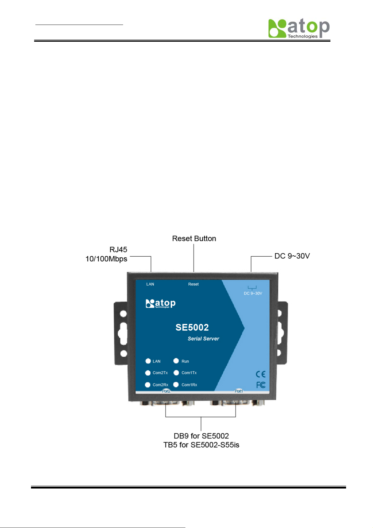
2 Hardware Description
NOTE:
1. SE5002 (for RS-232/422/485 without isolation ), SE5002-S55is (for RS422/485 with isolation)
2. Press the reset button of SE5002 to reset to the default value, shows the interface as below.
Fig 1. SE5002 Interfaces
LED Indicators:
Copyright © 2006 Atop Technologies, Inc.
All rights reserved. Designed in Taiwan.
1
Page 3

Quick Start Guide Version 1.3
ABLELink
SE5002
Off
Blinking with Green
Blinking with Orange
Off
Com 1(2)TX Blinking
Com 1(2)RX Blinking
On
Blinking (rate: 0.5 Sec) AP firmware running normally
®
Ethernet Serial Server
Fig. 1 LAN LED
Message Description
Ethernet Disconnected
Data transmitting on Ethernet at 100Mbps
Data transmitting on Ethernet at 10Mbps
Table 1. LAN LED Message
Fig. 1.
Fig. 2 COM Port LED
Message Description
No data transmitting on COM port
Data transmitting on COM port
Data Receiving on COM port
Table 2. COM Port LED Message
Fig. 2.
Fig. 3RUN LED
Message Description
Jumper JP1 Pin1 and Pin2 are shorted to disable AP firmware
Table 3. RUN LED Message
Fig. 3.
Installation Procedures:
Step 1: Connect SE5002 to power source
Step 2: Connect SE5002 to the Ethernet network. Use a standard straight-through Ethernet cable when
connect to a hub/switch, or connect to a PC‘s Ethernet port via a cross-over Ethernet cable. However,
Always make sure your PC is on the same network sub-net as SE5002.
Step 3: Connect SE5002’s serial port to a serial device.
Step 4: Mount SE5002 to a wall/panel with the screws included or Din-Rail rack (Require optional item model:
Din-Rail-Kit).
3 Software Setup
Default Network Setting: Default User Name/Password:
IP: 10.0.50.100 User Name: admin
Gateway: 10.0.0.254 Password: null (leave it blank)
Subnet: 255.255.0.0
Auto IP (Dynamic IP):
A DHCP server can automatically assigns the IP address and all the network settings. SE5002 supports the
DHCP client function. By default, the DHCP client function on SE5002 is disabled; you may activate the
DHCP client functions by executing SerialManager (Fig. 4)
Fig. 4. SerialManager utility Dialog Window
Assign a Static IP address by:
Copyright © 2006 Atop Technologies, Inc.
All rights reserved. Designed in Taiwan.
2
Page 4

Quick Start Guide Version 1.3
ABLELink
SE5002
A Configuration by Telnet
®
Ethernet Serial Server
1. Telnet to SE5002 using DOS command “Telnet IP_address”. Example: telnet 10.0.50.100
2. SE5002’s network, link mode and COM ports settings can be configured in the telnet window
B Configuration by SerialManager Utility
Use SerialManager on Product CD to configure the SE5002.First click” Configuration” then assign a
static IP.
C. Configuration by Web Browser
1. Make sure the PC is on the same network as SE5002
2. Open a web browser, then Enter in the IP address as the SE5002. The default user name is
admin and default password is null (leave it blank).
3. The SE5002’s network, link mode and COM ports settings can be configured on different web
pages.
4. Click “Save Configuration” to save settings.
5. Click ”Restart” button to initiate the change.
4 Pin Assignments
The pin assignments of DB9 connector on SE5002 is shown in the following table:
Pin#
1 DCD N/A N/A
2 RXD N/A (reserved)
3 TXD
4 DTR N/A N/A
5 SG (Signal Ground) SG (Signal Ground) SG (Signal Ground)
6 DSR N/A N/A
7 RTS
8 CTS N/A(reserved)
9 N/A N/A N/A
RS-232
Full Duplex
for SE5002 Model
DATA+
DATA- RXD-
RS-485
2 wire, Half Duplex
for SE5002 Model
RS-485/RS-422
4 wire, Full Duplex
for SE5002 Model
TXD+
RXD+
TXD-
The pin assignments of Terminal Block connector on SE5002-S55is is shown in the following table:
Pin#
1
2
3
4
5 SG (Signal Ground) SG (Signal Ground)
T+ NC
T- NC
R+ Data+
R- Data-
RS-485/RS-422
4 wire, Half Duplex
For SE5002-S55is
RS-485
2 wire, Full Duplex
For SE5002-S55is
Customer Services and Supports
1. Contact your local dealers or Atop Technical Support Center at the following numbers.
y +886-3-550-8137 (Atop Taiwan)
y +86-21-6495-6232 (Atop China)
2. Report the errors via Atop’s Web site or E-mail account
www.atop.com.tw, service@atop.com.tw
www.atop.com.cn, service@atop.com.cn
Copyright © 2006 Atop Technologies, Inc.
All rights reserved. Designed in Taiwan.
3
 Loading...