

Page 1
MB54XX-X
Modbus Gateway
User’s Manual
v. 1.1
December, 2012
Page 2

Atop Modbus Gateway
MB54XX-X Series
User’s Manual V 1.1
Tel.:
886-3-5508137
Fax:
886-3-5508131
Important Announcement
The information contained in this document is the property of Atop technologies, Inc., and is
supplied for the sole purpose of operation and maintenance of Atop Technologies, Inc.,
products. No part of this publication is to be used for any other purposes, and it is not to be
reproduced, copied, disclosed, transmitted, stored in a retrieval system, or translated into any
human or computer language, in any form, by any means, in whole or in part, without the prior
explicit written consent of Atop Technologies, Inc., offenders will be held liable for damages. All
rights, including rights created by patent grant or registration of a utility model or design, are
reserved.
Disclaimer
We have checked the contents of this manual for agreement with the hardware and software
described. Since deviations cannot be precluded entirely, we cannot guarantee full agreement.
However, the data in this manual is reviewed regularly and any necessary corrections included
in subsequent editions. Suggestions for improvement are welcome. All other product names
referenced herein are registered trademarks of their respective companies.
Published and printed by
Atop Technologies, Inc.
2F, No. 146, Sec. 1, Tung-Hsing Rd.
Jubei, Hsinchu 30261
Taiwan, R.O.C.
www.atop-tech.com
www.atop.com.tw
Copyright © 2011 Atop Technologies, Inc. All rights reserved. Technical data is subject to
change.
ii
Page 3

Atop Modbus Gateway
MB54XX-X Series
User’s Manual V 1.1
Table of Contents
Preface ....................................................................................................................................................... 2
1 Introduction ................................................................................................................................... 4
1.1 Overview ................................................................................................................................. 4
1.2 Features .................................................................................................................................. 6
2 Getting Started .............................................................................................................................. 7
2.1 Inside the Package ............................................................................................................... 7
2.2 Appearance, Front & Rear Panels .................................................................................... 9
2.3 First Time Installation ........................................................................................................ 12
2.4 Factory Default Settings ................................................................................................... 13
3 Configuration and Setup .......................................................................................................... 15
3.1 Locating and IP configuring using Device View© ..................................................... 15
3.2 Configuration using Web Interface ................................................................................ 17
3.2.1 LCM (Liquid Crystal Matrix) Configuring (MB5408-X/5416-X only) .. 19
3.2.2 Configure Automatic IP Assignment with DHCP .................................. 23
3.3 Web Overview ...................................................................................................................... 23
3.4 Network Configuration ...................................................................................................... 24
3.5 Basic Settings ..................................................................................................................... 26
3.5.1 COM Settings .................................................................................................. 26
3.5.2 Operation Mode .............................................................................................. 27
3.5.3 Serial Settings ................................................................................................ 27
3.5.4 VCOM Settings ............................................................................................... 28
3.5.5 TCP Settings ................................................................................................... 30
3.5.6 Slave ID Map ................................................................................................... 32
3.6 Advanced Settings ............................................................................................................. 34
3.6.1 SNMP Settings ................................................................................................ 34
3.6.2 Modbus ............................................................................................................. 35
3.7 Alert Configuration ............................................................................................................. 36
3.7.1 SMTP and Email Settings ............................................................................ 36
iii
Page 4

Atop Modbus Gateway
MB54XX-X Series
User’s Manual V 1.1
3.8 System ................................................................................................................................... 38
3.8.1 Log Settings .................................................................................................... 38
3.8.2 System Log ..................................................................................................... 39
3.8.3 Data Log ........................................................................................................... 40
3.8.4 Modbus Statistic ............................................................................................ 41
3.8.5 Time ................................................................................................................... 42
3.8.6 Security ............................................................................................................ 43
3.8.7 Import/Export .................................................................................................. 44
3.8.8 Factory Default ............................................................................................... 46
3.9 Restart ................................................................................................................................... 47
4 Applications and Examples ..................................................................................................... 48
4.1 Using ID offset range mapping ....................................................................................... 48
4.2 Using Alias ID mapping .................................................................................................... 50
5 Specifications .............................................................................................................................. 52
5.1 Hardware ............................................................................................................................... 52
5.2 Software ................................................................................................................................ 60
Appendix Configuration using Telnet Interface................................................... 61
Warranty ................................................................................................................................................... 80
iv
Page 5

Atop Modbus Gateway
MB54XX-X Series
User’s Manual V 1.1
Preface
Purpose of the Manual
This manual supports you during the installation and configuring of the MB54XX Modbus
Gateway Series only, as well as it explains some technical options available with the
mentioned product. As such, it contains some advanced network management knowledge,
instructions, examples, guidelines and general theories designed to help users manage this
device and its corresponding software; a background in general theory is a must when reading
it. Please refer to the Glossary for technical terms and abbreviations (if any).
Who Should Use This User Manual
This manual is to be used by qualified network personnel or support technician who are
familiar with network operations; it might be useful for system programmers or network
planners as well. This manual also provides helpful and handy information for first time users.
For any related problems please contact your local distributor, should they be unable to assist
you, please redirect your inquiries to www.atop.com.tw or www.atop-tech.com .
Supported Platform
This manual is designed for the MB54XX Modbus Gateway Series and that series only.
Warranty Period
We provide a 5 year limited warranty for the MB54XX Modbus Gateway Series.
Manufacturers Federal Communication Commission Declaration of
Conformity Statement
Model: MB54XX Modbus Gateway Series
NOTE: This equipment has been tested and found to comply with the limits for a Class A digital
device, pursuant to Part 15 of the FCC Rules. These limits are designed to provide reasonable
protection against harmful interference when the equipment is operated in a commercial
environment. This equipment generates, uses, and can radiate radio frequency energy and, if
not installed and used in accordance with the instruction manual, may cause harmful
2
Page 6

Atop Modbus Gateway
MB54XX-X Series
User’s Manual V 1.1
interference to radio communications. Operation of this equipment in a residential area is likely
to cause harmful interference in which case the user will be required to correct the interference
at his own expense.
This device complies with Part 15 of the FCC Rules. Operation is subject to the following two
conditions:
1 This device may not cause harmful interference, and
2 This device must accept any interference received, including interference that may cause
undesired operation.
3
Page 7
Atop Modbus Gateway
MB54XX-X Series
User’s Manual V 1.1
1 Introduction
1.1 Overview
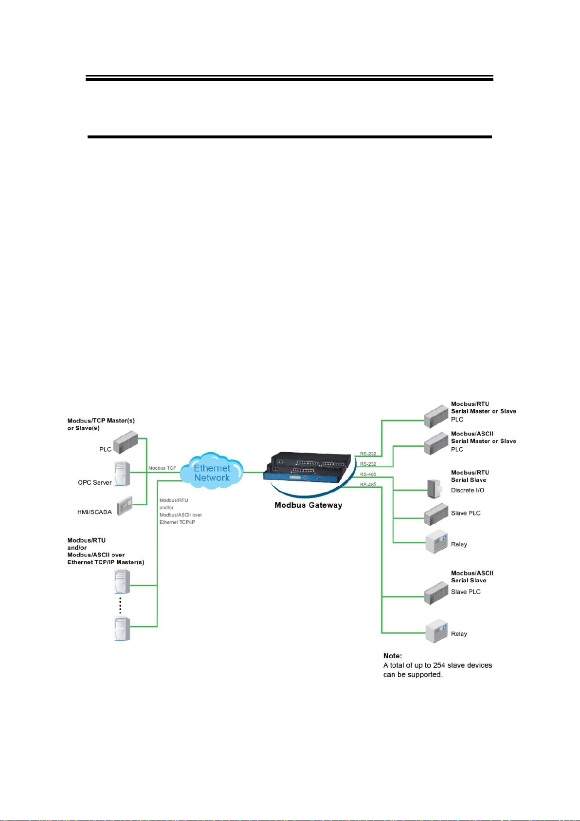
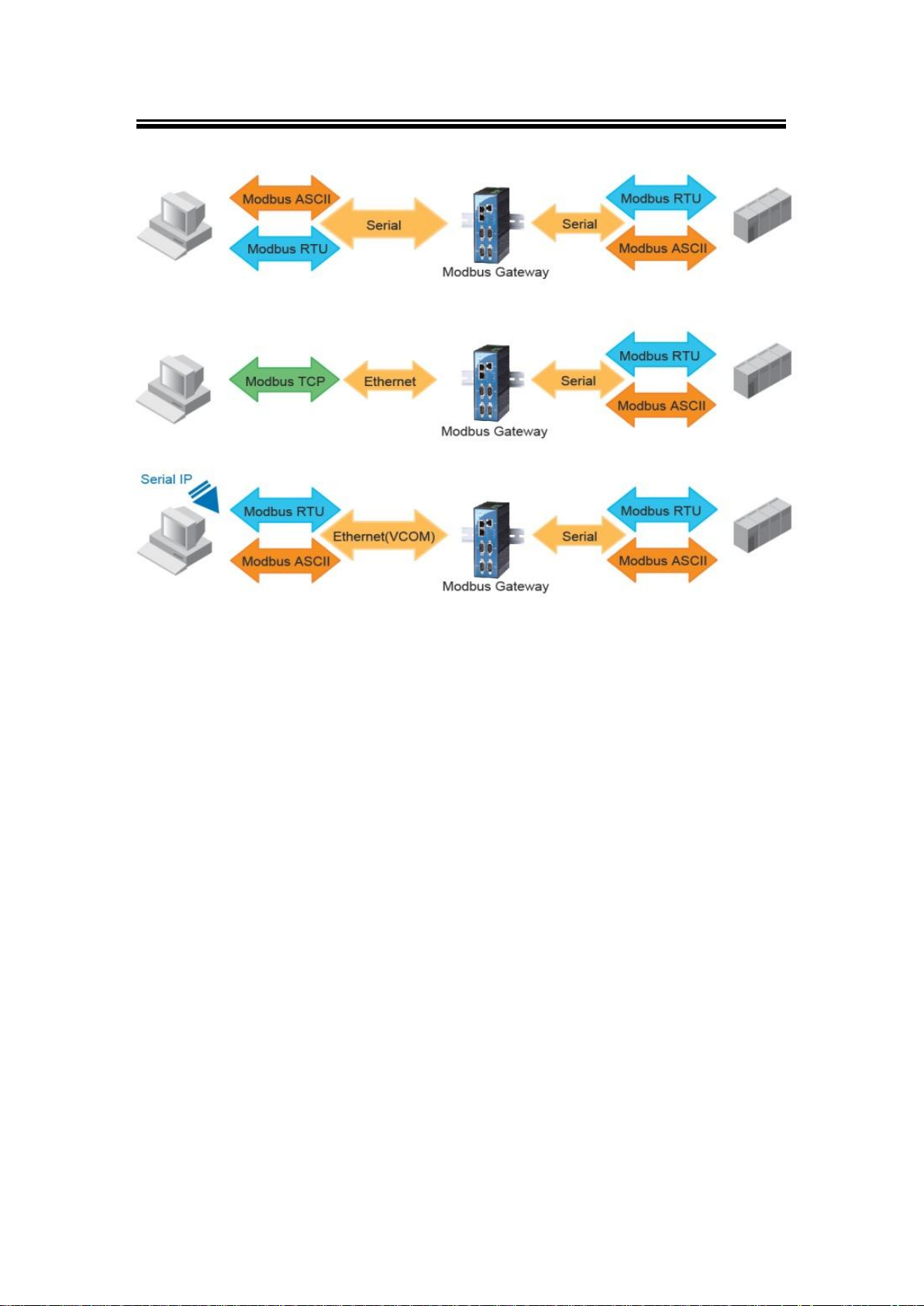
The Modbus Gateway is an interface between Modbus Gateway and computer hosts running
Modbus/TCP on Ethernet networks. Fully compliant with Modbus/TCP, the Modbus Gateway
offers a convenient solution to connect existing devices or controllers running Modbus serial
protocol (Modbus/ASCII or Modbus/RTU) to an Ethernet network. The MB54XX Series are
standard Modbus gateways that convert between Modbus TCP and Modbus RTU/ASCII
protocols.
The MB54XX Series support 16 simultaneous TCP master and 32 simultaneous requests for
each TCP master. Each RS-232/422/485 serial port can be individually configured for Modbus
RTU or Modbus ASCII operation or even different baudrate, allowing both types of networks to
be fully integrated with Modbus TCP within one package.
Fig. 1. 1
4
Page 8
Atop Modbus Gateway
MB54XX-X Series
User’s Manual V 1.1
Fig. 1. 2
5
Page 9

Atop Modbus Gateway
MB54XX-X Series
User’s Manual V 1.1
Never install or work on electrical or cabling during periods of lighting activity. Never
connect or disconnect power when hazardous gases are present.
WARNING: Disconnect the power and allow to cool 5 minutes before touching.
1.2 Features
RISC 32-bit 266 MHz CPU
Standard 19-inch rack-mount 1U high metal housing
Software selectable RS-232/RS-485/RS-422 RJ-45 connection
Dual 10/100 Mbps Ethernet ports for network redundancy
Configurable via LCM buttons, Serial console, Telnet, Web and Windows-based utility
program Device View©
Relay output indicator for network link status
LCM indication with 4 keypad settings
Convert between Modbus TCP and Modbus RTU/ASCII
2 Ethernet port and 4,8, or 16 RS-232/422/485 ports
Supports 16 simultaneous TCP masters with up to 32 simultaneous requests per master
Easy hardware setup and configuration
Caution
Beginning from here there will be extreme caution exercised.
6
Page 10

Atop Modbus Gateway
MB54XX-X Series
User’s Manual V 1.1
Table 2. 1
Item
Quantity
Description
MB54XX Series
1
Modbus Gateway
Cable
1
RJ-45 to Male DB9 cable
Mounting Kit
1
Rack Mounting Type-L angles (x 2)
Screws (x 6)
Foot Rubbers
Documentation + CD
Inside the CD you will find:
User’s Manual
Installation Guide
Device View© utility
Installation Guide + Warranty Card
2 Getting Started
2.1 Inside the Package
Inside the purchased you will find the following items.
7
Page 11

Atop Modbus Gateway
MB54XX-X Series
User’s Manual V 1.1
Table 2. 2
Item
Description
MB5404D-X
4-Port Serial-to-Ethernet Intelligent Modbus Gateway, D-Sub(M)
MB5404D-Sis-X
4-Port Serial-to-Ethernet Intelligent Modbus Gateway, Terminal Block, 2 KV Isolation
MB5408-X (US)
8-Port Serial-to-Ethernet Intelligent Modbus Gateway with RJ45 connectors, AC
100-240V, US power plug
MB5408-X (EU)
8-Port Serial-to-Ethernet Intelligent Modbus Gateway with RJ45 connectors, AC
100-240V, EU power plug
MB5416-X (US)
16-Port Serial-to-Ethernet Intelligent Modbus Gateway with RJ45 connectors, AC
100-240V, US power plug
MB5416-X (EU)
16-Port Serial-to-Ethernet Intelligent Modbus Gateway with RJ45 connectors, AC
100-240V, EU power plug
How to order
Please refer to the following product codes to place an order.
Note: Notify your sales representative immediately if any of the above items is missing or
damaged upon delivery.
8
Page 12
Atop Modbus Gateway
MB54XX-X Series
User’s Manual V 1.1
Fig. 2. 1
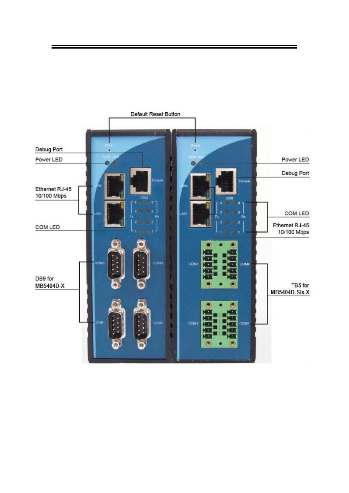
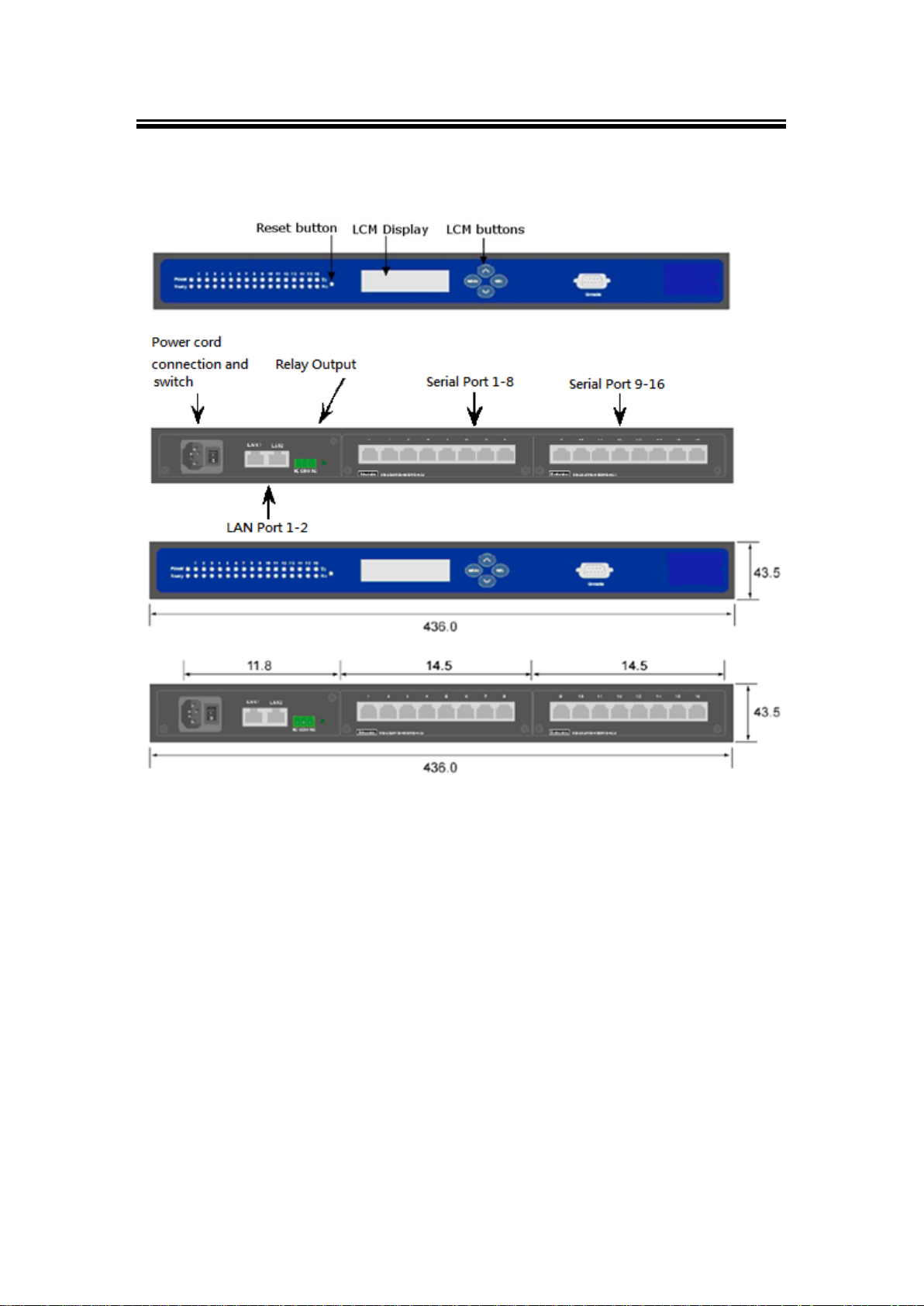
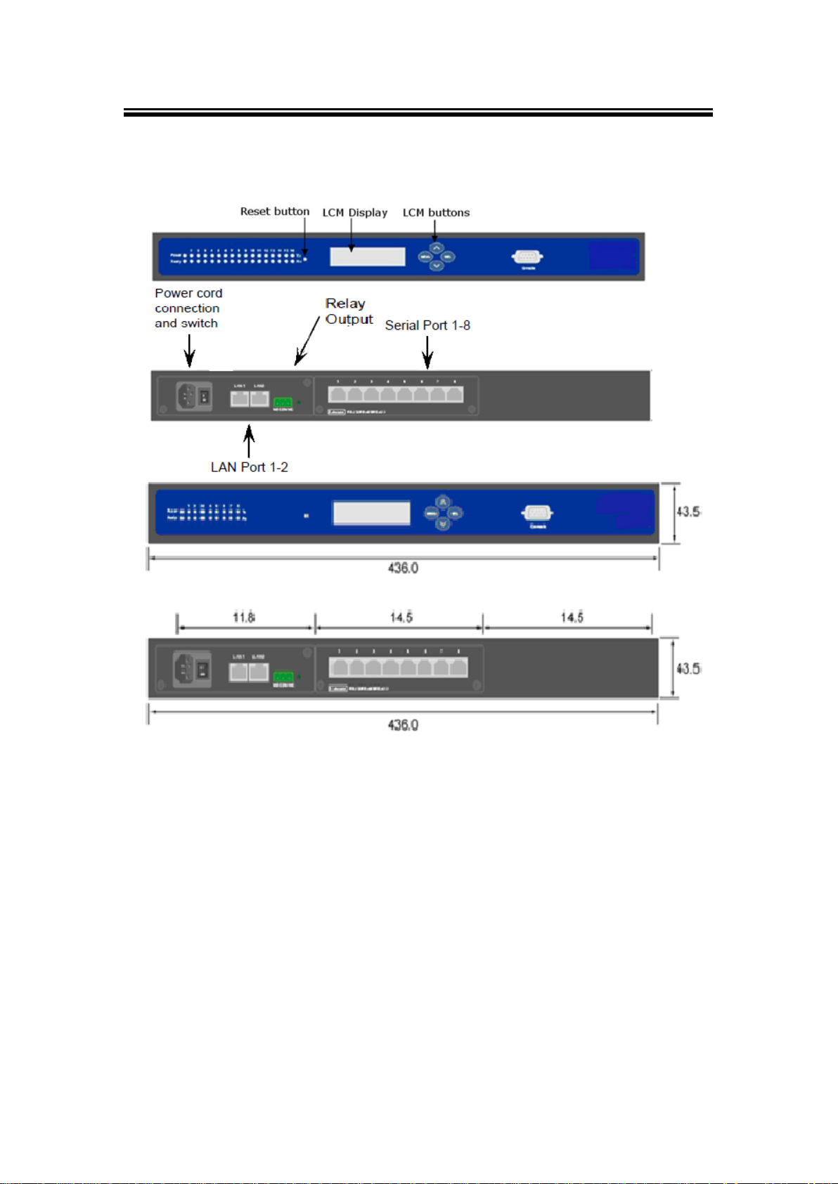
2.2 Appearance, Front & Rear Panels
The following figures show the device’s front and rear panels.
MB5404D-X (Left) / MB5404D-Sis-X (Right) Front Panel
9
Page 13
Atop Modbus Gateway
MB54XX-X Series
User’s Manual V 1.1
Fig. 2. 2
MB5416-X Front and Rear Panel
10
Page 14
Atop Modbus Gateway
MB54XX-X Series
User’s Manual V 1.1
Fig. 2. 3
MB5408-X Front and Rear Panel
11
Page 15

Atop Modbus Gateway
MB54XX-X Series
User’s Manual V 1.1
2.3 First Time Installation
Before installing the device, please adhere to all safety procedures described below, Atop will
not be held liable for any damages to property or personal injuries resulting from the
installation or overall use of the device. Do not attempt to manipulate the product in any way if
unsure of the steps described here, in such cases please contact your dealer immediately.
1. Prepare the necessary cables, DC adapter, power cord, LAN cable, etc.; do not connect
the unit yet.
2. Plug in the Power Supply/Adapter (MB5404D-X/MB5404D-Sis-X) or AC power cord
(MB5408/5416-X) to a power outlet and turn on the power switch (please make sure the
electric outlet has proper grounding so as to not cause damage to the unit, property or
yourself); shortly thereafter the unit will beep once and the LCM Display will show a .
3. Within one minute, the buzzer shall beep once, and the LCM Display shall show the
model’s name.
4. Connect LAN1 to a network switch or to your LAN network with a UTP cable, and
connect a host PC to your LAN network with another cable.
5. Connect a serial device to one of the serial ports, and make sure a correct cable is used
(Pin assignments for a RS-232 device and for a RS-485 cable are shown in )
For more information on how to install the device, please refer to the Installation Guide
available in your package.
12
Page 16

Atop Modbus Gateway
MB54XX-X Series
User’s Manual V 1.1
Interface
Device IP
Subnet mask
Gateway IP
LAN 1
10.0.50.100
255.255.0.0
10.0.0.254
Table 2. 4
Parameter
Default Values
Modbus Master
TCP Settings
TCP Master
Mode: TCP Master
Port: 502
Modbus Slave
MB5416-X:COM1 – COM16
MB5408-X:COM1– COM8
MB5404D-X: COM1– COM4
MB5404D-Sis-X: COM1– COM4
Mode: RTU Slave
Serial Configuration: RS-232, 9600 bps, 8 data bits, None Parity bit,
1 stop bit, None Flow Control, Buffer Disabled,
2.4 Factory Default Settings
Network Defaults
Note that the Modbus Gateway comes with one IP address for redundant Ethernet interfaces.
Table 2. 3
Modbus Default
13
Page 17

Atop Modbus Gateway
MB54XX-X Series
User’s Manual V 1.1
Table 2. 5
Parameter
Default Values
Security
User Name
Admin
Password
Null (blank)
SNMP
SysName of SNMP
0060E9-XXXXXX
SysLocation of SNMP
Location
SysContact of SNMP
Contact
SNMP
Enable
Read Community
Public
Write Community
Private
SNMP Trap Server
0.0.0.0
Other Default Settings are shown in the following table:
Note: you can press the “Reset” button on the front panel for 5 seconds (see Sec. 3.8.8 and
3.9), to restore the server to factory default settings.
14
Page 18
Atop Modbus Gateway
MB54XX-X Series
User’s Manual V 1.1
3 Configuration and Setup
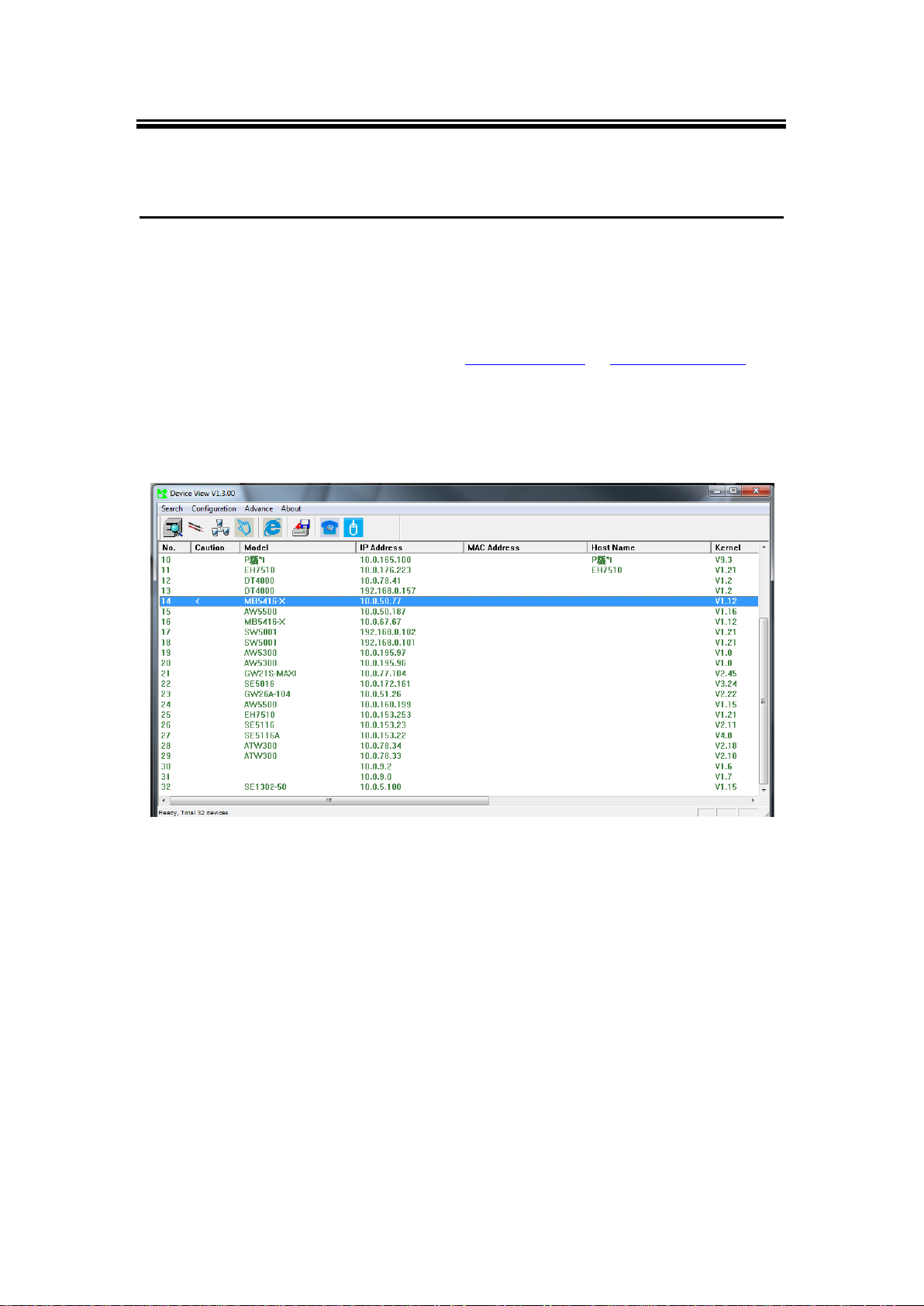
3.1 Locating and IP configuring using Device View©
First, please install our configuration utility program Device View© that comes with the
Product CD or download it from our websites (www.atop.com.tw or www.atop-tech.com). For
more information on how to install Device View© , please refer to the manual that comes in the
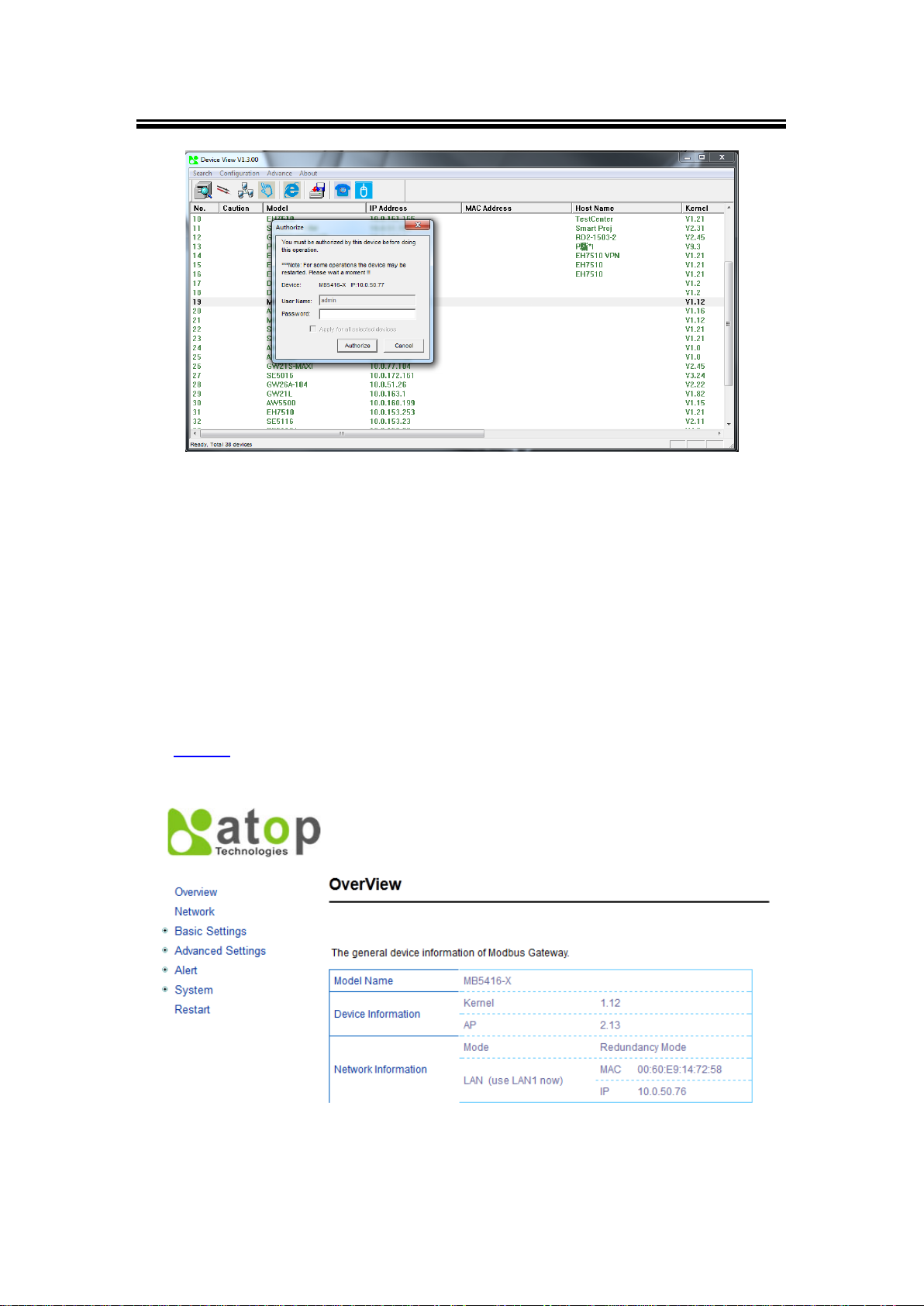
utility CD. To find the Modbus Gateway device on your network, press “Scan”, a list of devices
currently connected to the network will be shown in the window.
The device might not be in the same subnet as your PC, because of this you will have to use
our utility to locate it in your virtual environment. To configure each device, click the selected
device (default IP: 10.0.50.100), and login with the default username and password. After
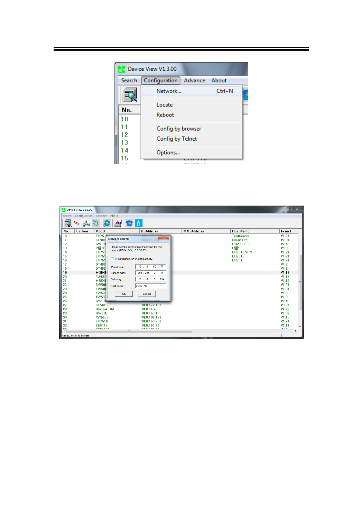
successful login, click “Configuration >Network…” (Or Ctrl+N), and a pop-up window will
appear as follows,
Fig. 3. 1
Note: for illustration purpose only, actual values/settings may vary between devices.
15
Page 19
Atop Modbus Gateway
MB54XX-X Series
User’s Manual V 1.1
Fig. 3. 2
Fig. 3. 3
You may proceed then to change the IP address, to avoid any IP address conflict with other
hosts on your LAN network or to connect the device to your existing LAN. The system will
prompt you to Authorize whether you can do these changes or not, i.e., it will ask you for the
Username and Password, (Fig. 3.4).
16
Page 20
Atop Modbus Gateway
MB54XX-X Series
User’s Manual V 1.1
Fig. 3. 5
Fig. 3. 4
Please consult your system administrator if you do not know your network subnet mask and
gateway address. If your LAN network address begins with 192.168.X.X, then please use the
LAN2 interface for configuration.
3.2 Configuration using Web Interface
Every MB54XX Modbus Gateway device is equipped with a built-in Web server in the firmware.
Therefore, it can be accessed by using a browser for configuration by entering the device’s IP
(see Sec. 2.4 for default value).
17
Page 21
Atop Modbus Gateway
MB54XX-X Series
User’s Manual V 1.1
Fig. 3. 6
This type of configuration is the most user-friendly, most recommended and most common
method used on your MB54XX Modbus Gateway. Please go to its corresponding section for a
detailed explanation.
18
Page 22
Atop Modbus Gateway
MB54XX-X Series
User’s Manual V 1.1
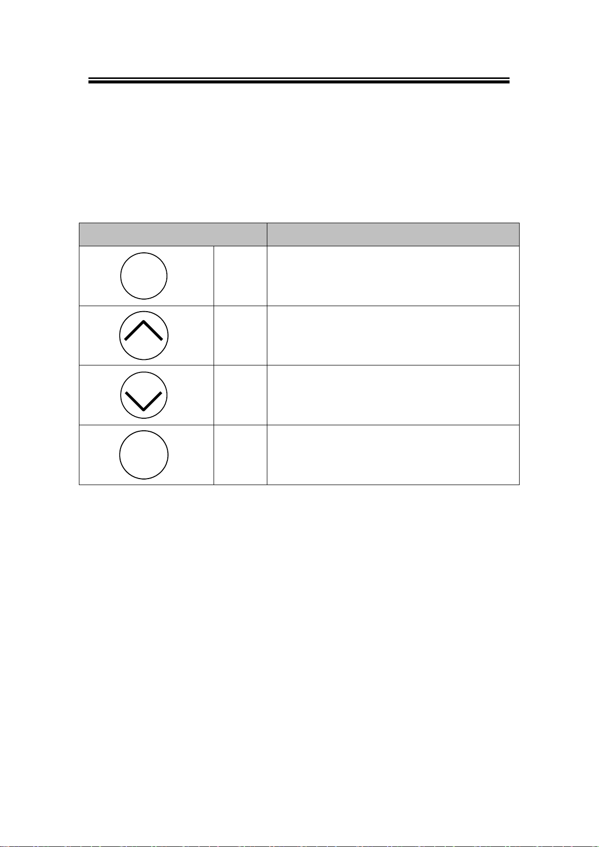
Buttons
Button Description
Menu
<Menu>
Open Main Menu, or to return to the previous Menu
<Up>
Scroll up
<Down>
Scroll down
SEL
<SEL>
Select
3.2.1 LCM (Liquid Crystal Matrix) Configuring (MB5408-X/5416-X only)
The device also has the option of manual configuration (without the software), by making use
of its interactive console. Using this method is however, very easy and intuitive; buttons and
their functions are described next.
Table 3. 1
Example
To change the device’s IP address, follow the approach below.
Press <Menu> to enter Main Menu
Press <Down> to scroll down to 2. Network Set
Press <SEL> to enter Network setting and then <Up>/<Down> to scroll up or down to
LAN1
Press <SEL> to enter LAN1 and then <Down> to scroll down to 1. IP Config
Press <SEL> to enter LAN1 IP Config and then press <Down> to scroll down to 1.
Static, finally press <SEL> to save the selection.
Press <SEL><Down> to enter 2. IP Address. Use <Up>/<Down> to increase or
decrease the Digital of IP Address, press <Menu> to return to one level higher after
completion
19
Page 23

Atop Modbus Gateway
MB54XX-X Series
User’s Manual V 1.1
Table 3. 2
1st layer
2nd layer
3rd layer
4th layer
5th layer
Descriptions
1.Overview
1. Model name
Display Model name
2. Kernel ver.
Display kernel version
3. AP ver.
Display AP version
4. Lan 1
1.Lan status
Display status of LAN1
2.MAC
Display MAC address of LAN1
5. Lan 2
1.Lan status
Display LAN of LAN2
2.MAC
Display MAC address of LAN2
2.Network set
1.Lan 1
1.IP config
1.Static IP
Display/Change static IP
2.DHCP
Display dynamic IP or enable
DHCP
2.IP address
Display/Change LAN1 IP
3.Net mask
Display/ Change Net mask
4.Gateway
Display/Change the Gateway IP
2.DNS server1
Display or Change 1st DNS IP
address
3.DNS server2
Display or Change 2nd DNS IP
address
3.Serial set
1.Select port
Select COM Port: SE5016:
[1]~[16] / SE5008: [1]~[8]
To enter: 3. Net mask Use <Up>/<Down> to increase or decrease the Digital of
subnet mask and then <Menu> to return to one level higher after completion
To enter: 4. Gateway. Use <Up>/<Down> to increase the Digital of default gateway
and use <Menu> to return to one level higher after completion
Press <SEL> to the end of the menu to return to one level higher and the device shall
display System message “Save & Restart”. Push <SEL> to 2. Yes, and <SEL>
again after completion. The device shall restart and the new settings will appear.
The LCM command structure is as follows, Table.
20
Page 24

Atop Modbus Gateway
MB54XX-X Series
User’s Manual V 1.1
2.Parameter set
1.Baud Rate
1. 300
Display or Change baud rate
2. 600
3. 1200
4. 2400
5. 4800
6. 9600
7. 19200
8. 38400
9. 57600
10. 115200
11. 230400
12. 460800
13. 921600
2.Parity
1. None
Display or Change Parity mode
2. Odd
3. Even
4. Mark
5.Space
3.Data bits
1. 5 bits
Display or Change Data bit length
2. 6 bits
3. 7 bits
4. 8 bits
4.Stop bits
1. 1 bits
Display or Change Stop bit length
2. 2 bits
5.Flow control
1. None
Display or Change Flow control
mode
2. Xon/Xoff
3. Hardware
21
Page 25

Atop Modbus Gateway
MB54XX-X Series
User’s Manual V 1.1
6.UART mode
1. 232
Display or Change UART mode for
RS-232
2. 422
Display or Change UART for
RS-422
3. 485
Display or Change UART for
RS-485
7.Apply to all
1.No
2.Yes
Apply UART setting to all serial
ports
4.Server state
1.Console
1.Web console
1.Disable
Disable Web console
2.Enable
Enable Web console
2.Telnet console
1.Disable
Disable Telnet console
2.Enable
Enable Telnet console
2.Pwd protection
1.LCM console
1.No
Disable LCM console password
protection
2.Yes
Enable and change the password
2.Reset button
1.No
Disable the Reset button
password protection
2.Yes
Enable and change the password
on Reset button
3.Ping
1.Lan 1
Use "ping" command to check
specific IP address for LAN1
2.Lan 2
Use "ping" command to check
specific IP address for LAN2
5.Restart
1.No
Cancel Restart command
2.Yes
Restart immediately
22
Page 26
Atop Modbus Gateway
MB54XX-X Series
User’s Manual V 1.1
3.2.2 Configure Automatic IP Assignment with DHCP
A DHCP server can automatically assign addresses to LAN1 or LAN2, the Subnet Mask, and
the Gateway. You can simply check “DHCP” box in the Network Setting dialog using our
Device View© utility and then restart it; once restarted it will be automatically configured.
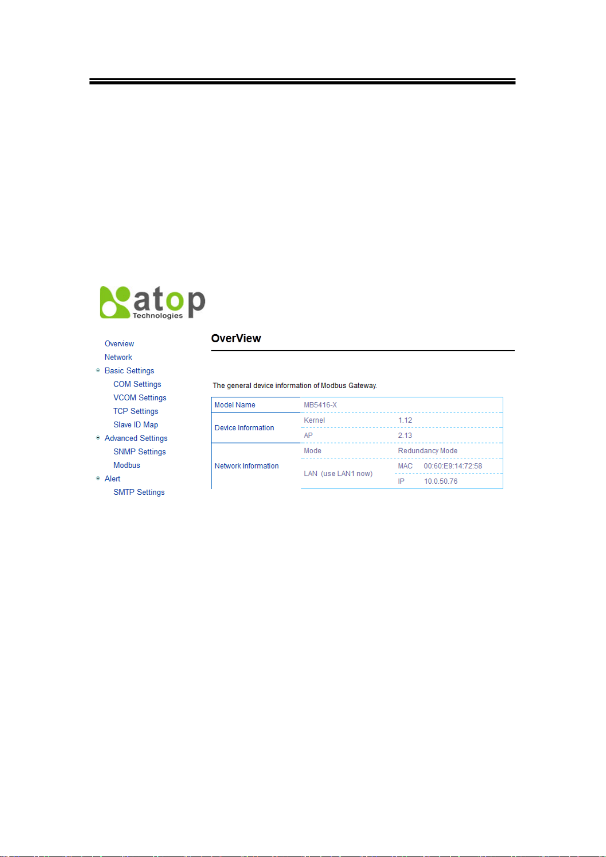
3.3 Web Overview
In this section, only current information on the device’s status and settings will be displayed.
Fig. 3. 7
Model Name as its name implies, shows the device’s model.
Device Information displays information on the Kernel version, as well as the AP
Network Information here you may find the Mode in which the device is currently
working on (Dual Subnet, Redundancy Mode), and both LANs respective MAC and IP
addresses.
Dual Subnet Mode: in which two Ethernet ports have separate IP addresses and
subnets
Redundancy Mode: the system will just use one port for data transfer, if this port is
disconnected, the whole system will change to another port automatically.
23
Page 27

Atop Modbus Gateway
MB54XX-X Series
User’s Manual V 1.1
3.4 Network Configuration
In this section, IP, Subnet Mask and overall connectivity settings can be accessed. When on
Redundancy Mode the device will have the two LAN ports connected1 to the Network, but the
signal will flow through one of them. In the case one line is out due to any reason there will still
be another route so the signal can keep flowing.
Note1: you can still connect only one LAN port to the device, though you can still change the settings in it, there won’t
be a Redundancy function.
Fig. 3. 8
24
Page 28

Atop Modbus Gateway
MB54XX-X Series
User’s Manual V 1.1
When the device is set on Dual Subnet Mode, a set of two IP addresses can be used without
having Redundancy. This is especially useful when using two different networks.
Fig. 3. 9
25
Page 29

Atop Modbus Gateway
MB54XX-X Series
User’s Manual V 1.1
3.5 Basic Settings
3.5.1 COM Settings
This section is responsible for settings on your physical ports, (may them be COM or serial).
Fig. 3. 10
26
Page 30

Atop Modbus Gateway
MB54XX-X Series
User’s Manual V 1.1
3.5.2 Operation Mode
RTU Slave: when working as a slave node, the device will wait and accept request from
its master; data transfer is done under an RTU format.
RTU Master: when working as a master node, the device will issue commands to the
slave node; data transfer is under an RTU format.
ASCII Slave: when working as a slave node, the device will wait and accept request from
its own master; data transfer is under an ASCII format.
ASCII Master: when working as a master node, the device will issue commands to the
slave node; data transfer is under an ASCII format.
3.5.3 Serial Settings
This section has the following selections:
RS-232/RS-422/RS-485 Software Selectable (Default: RS-232)
Baud-rate: 110 bps ~ 921600 bps
Parity: None, Even, Odd, Mark, or Space
Data Bits: 5, 6, 7, or 8
Stop Bits: 1 or 2
Flow Control: None, Hardware CTS/RTS, Software Xon/Xoff
Apply to all Serial Ports Alternatively, the settings can be chosen to apply to all Serial Ports if
needed by checking the last box on the options.
27
Page 31

Atop Modbus Gateway
MB54XX-X Series
User’s Manual V 1.1
3.5.4 VCOM Settings
Generates a virtual Serial (COM) port within the device by the network connection, it is a TCP
connection but the encoding is an Atop Technologies’ exclusive private protocol. There is the
choice to set your device as either a Master or a Slave in your network.
You will need a VCOM setting, proceed to go to Basic Settings → VCOM Settings and tick
on the VCOM’s “Enable” box to allow configuration on the port selected.
The options for Master are similar, the only difference being on the device’s function.
Fig. 3. 11
Choose whether your device conforms as an RTU or ASCII, which is the VCOM Mode.
VCOM Port Using the TCP, the device listens whether there are any clients (VCOM
clients), connecting (Serial-IP) to its ports.
VCOM Mode Its definition is analogous to the one in Sec. 3.5.2.
Note: Windows has its own restrictive Serial-IP software installed for use.
28
Page 32

Atop Modbus Gateway
MB54XX-X Series
User’s Manual V 1.1
Fig. 3. 12
VCOM inactivity’s Time Out can be set as well (which is the period of time allowed
between actions), with a maximum of 600 minutes or 10 hours. If no action has been
taken after this period, VCOM connection will be automatically interrupted by the system.
It is important to note that alternatively, these settings can be chosen to be applied to All
VCOMs if needed by checking the last box on the options.
Click on Save Configuration to keep all changes made.
Fig. 3. 13
29
Page 33

Atop Modbus Gateway
MB54XX-X Series
User’s Manual V 1.1
3.5.5 TCP Settings
Settings for representing a Modbus TCP connection using the internet are set here. First go
to Basic Settings ↔ TCP Settings, then proceed to choose whether to enable TCP ticking on
the “Enable” box.
TCP Slave: When on this mode, the device will run on Slave mode and wait to receive
Remote IP Address shows the device’s slave node IP address.
TCP Port shows the device’s slave node TCP port.
VCOM inactivity’s Time Out can be set as well (which is the period of time allowed
Fig. 3. 14
Modbus requests from the Master; data transmission is done under a Modbus TCP
format.
between actions), with a maximum of 600 minutes or 10 hours. If no action has been
taken after this period, Modbus TCP connection will be automatically terminated by the
system.
30
Page 34

Atop Modbus Gateway
MB54XX-X Series
User’s Manual V 1.1
Fig. 3. 15
On Operation Mode choose whether the device is going to be a Slave or a Master. Remote IP
Address refers to the IP belonging to the device that is going to be controlled from your
MB54XX Series; this option is not available when the device is set as a Master. TCP Port is the
port through which the signal is going to be relayed upon. And again, there is a TCP Inactivity
Time Out with the same 10 hours maximum value as stated on the last section. Configuration
can be saved as well.
31
Page 35

Atop Modbus Gateway
MB54XX-X Series
User’s Manual V 1.1
3.5.6 Slave ID Map
The system uses the Modbus ID to route Modbus’ request commands (from the master node)
to the respective slave node; it is paramount to define ID maps for each slave node. For every
slave node, there must be a correct Virtual ID (Alias ID) and Real ID defined in the maps.
Fig. 3. 16
32
Page 36

Atop Modbus Gateway
MB54XX-X Series
User’s Manual V 1.1
Slave Interface
When a port is set to slave mode, a Slave interface will be then created for you. Select the
Slave Interface, which is the COM/VCOM/TCP port; then select Alias Mode or Offset Mode
to modify the range and offset as you needed.
Alias Mode maps a virtual ID to a real ID each at the time.
Alias ID which refers to a Virtual ID for the reading Master node.
Real ID which is the real ID from the slave node.
Offset Mode which refers to a range of defined ID maps.
Slave ID Start Virtual ID’s start number.
Slave ID End Virtual ID’s end number.
Slave ID Offset Real ID range, which is from (Slave ID Start -Offset) to (Slave ID
End-Offset).
Note: on VCOM, TCP and COM, Master and Slave IDs can be set, while on COM and VCOM work only with Serial
ports.
Fig. 3. 17
33
Page 37

Atop Modbus Gateway
MB54XX-X Series
User’s Manual V 1.1
3.6 Advanced Settings
3.6.1 SNMP Settings
SNMP Settings determines whether your device settings can be viewed with standard SNMP
software; by default it is disabled.
SysName which is by default the MAC address
SysLocation refers to the device’s physical location.
SysContact is the device administrator’s contact information.
If you wish to make the information available for public viewing by a Read Community, simply
check the “Enable SNMP” box and fill in “Public_viewers” in Read Community field. If you
wish to allow a group of people called “Power_users” to change the information, enter
“Power_users” in Write Community. If you allow a trap server to collect device information,
please fill in SNMP Trap Server with its corresponding IP address (the trap server designed to
collect all alarm information). Configuration will take effect after the device is restarted.
Fig. 3. 18
34
Page 38

Atop Modbus Gateway
MB54XX-X Series
User’s Manual V 1.1
3.6.2 Modbus
In Modbus settings, you could select whether to enable Modbus Exception or not. If the
Modbus’ slave produces no response, timeout occurs, it may then be necessary for the
gateway to return an Exception, and setting the Response timeout as follows.
Configure timeout for each COM port
Configure timeout for TCP/ VCOM port
Fig. 3. 19
35
Page 39

Atop Modbus Gateway
MB54XX-X Series
User’s Manual V 1.1
3.7 Alert Configuration
3.7.1 SMTP and Email Settings
In Alert Events, you can configure options to let your Modbus Gateway to send out device
information to alert users, administrators, or responsible personnel. There are five anomalies
defined in it to trigger alert functions.
Cold Start, power supply is interrupted.
Warm Start, the device Restart function is used, (either by pressing a button or by its
interface).
Authentication Fail, incorrect username and password are entered.
IP address change, device’s IP address is changed.
Password Changed, authentication password is changed.
Fig. 3. 20
36
Page 40

Atop Modbus Gateway
MB54XX-X Series
User’s Manual V 1.1
When enabled, an E-mail alert would be sent to the designated E-mail address in the E-Mail
Settings. To setup an email alert function, you first need to configure the recipient’s email
address and the mail server.
Fig. 3. 21
37
Page 41

Atop Modbus Gateway
MB54XX-X Series
User’s Manual V 1.1
3.8 System
3.8.1 Log Settings
This section lets you change the way your report will be shown on your Log.
Fig. 3. 22
38
Page 42

Atop Modbus Gateway
MB54XX-X Series
User’s Manual V 1.1
3.8.2 System Log
This section merely shows a list of system running events currently (with every event’s
properties displayed), as well as the option to clear them all.
Fig. 3. 23
39
Page 43

Atop Modbus Gateway
MB54XX-X Series
User’s Manual V 1.1
3.8.3 Data Log
Event filtering is available in this section for analysis; a number of options are available for a
customized analysis. Traffic in the system can be done here as well.
Fig. 3. 24
40
Page 44

Atop Modbus Gateway
MB54XX-X Series
User’s Manual V 1.1
3.8.4 Modbus Statistic
All ports’ information is available in this section.
Fig. 3. 25
41
Page 45

Atop Modbus Gateway
MB54XX-X Series
User’s Manual V 1.1
3.8.5 Time
Date and time can be set manually, or using Network Time Protocol (NTP) to automatically
synchronizes with a Time Server. For auto-synching check the box below NTP Server
Settings “Obtain date/time automatically” proceeding then to fill the IP address or
hostname for it. If a hostname is entered, the DNS server must be configured properly; a Time
Zone can be selected as well, Fig. 3.26.
Fig. 3. 26
42
Page 46

Atop Modbus Gateway
MB54XX-X Series
User’s Manual V 1.1
3.8.6 Security
Password settings are available at this section, as well as device’s console configuration
settings allowing users to limit the way they are able to configure the device.
Fig. 3. 27
43
Page 47

Atop Modbus Gateway
MB54XX-X Series
User’s Manual V 1.1
3.8.7 Import/Export
Once all the configurations are set and the device is working properly, you may want to backup
(Export) your configuration. Backup can be used when the new firmware is uploaded and it is
reset to a factory default settings, it is done to prevent accidental loading of incompatible old
settings. The backup file could also be used to efficiently deploy multiple Modbus Gateways of
similar settings by restoring the settings to the devices by Importing the corresponding file.
Fig. 3. 28
44
Page 48

Atop Modbus Gateway
MB54XX-X Series
User’s Manual V 1.1
Fig. 3. 29
Fig. 3. 30
45
Page 49

Atop Modbus Gateway
MB54XX-X Series
User’s Manual V 1.1
3.8.8 Factory Default
A simple return to Factory Default is available in our MB54XX Series.
Fig. 3. 31
46
Page 50

Atop Modbus Gateway
MB54XX-X Series
User’s Manual V 1.1
3.9 Restart
Restart is just a click away in our Modbus Series.
Fig. 3. 32
47
Page 51

Atop Modbus Gateway
MB54XX-X Series
User’s Manual V 1.1
4 Applications and Examples
On your device two different ID mapping definitions are given by the system, both using
Modbus ID to route the requesting command (from the Master) to the Slave node.
4.1 Using ID offset range mapping
If the Slave ID is continuous, it is recommended to use the Offset mode, Fig. 4.1.
Fig. 4. 1
48
Page 52

Atop Modbus Gateway
MB54XX-X Series
User’s Manual V 1.1
Fig. 4. 2
49
Page 53

Atop Modbus Gateway
MB54XX-X Series
User’s Manual V 1.1
4.2 Using Alias ID mapping
This is only recommended if the ID is not continuous, Fig. 4.3.
Fig. 4. 3
50
Page 54

Atop Modbus Gateway
MB54XX-X Series
User’s Manual V 1.1
Fig. 4. 4
51
Page 55

Atop Modbus Gateway
MB54XX-X Series
User’s Manual V 1.1
Table 5. 1
System
CPU
32-bit 266MHz RISC Processor with MMU
Flash Memory
2 + 8 MB (2MB for Bootloader)
RAM
128 MB DDR
EEPROM
8 KB
Reset
Built-in Recessed Key (Restore to Factory Defaults)
Watchdog
Hardware built-in
Network
Ethernet Interface
IEEE 802.3 Compliance
Dual Port 10/100Mbps Auto-Detection
Connection: RJ-45
Auto MDI/MDI-X: No
Protection
Built-in 1.5 KV Magnetic Isolation
Protocol
ICMP
TCP/IP
UDP
HTTP, ,
T
e
l
n
e
t
D
N
S
D
H
C
P
SMTP
NTP
ARP
5 Specifications
5.1 Hardware
52
Page 56

Atop Modbus Gateway
MB54XX-X Series
User’s Manual V 1.1
C
l
i
e
n
t
S
N
M
P
Serial
Serial Interface
RS-232/RS-422/RS-485 Software Selectable (Default: RS-232)
Serial Connector
RJ45 Connector Type
MB5416-X ---16 Serial Ports
MB5408-X --- 8 Serial Ports
DB9 (9-pin) Connector type
MB5404D-X
TB5 (5-pin) Connector type
MB5404D-Sis-X
Serial Port
Communication
Baud-rate: 300 bps ~ 921600 bps (MB5404D-X, MB5408-X,MB5416-X)
300 bps ~ 230400 bps (MB5404D-Sis-X)
Parity: None, Even, Odd, Mark, or Space
Data Bits: 7, or 8
Stop Bits: 1 or 2
Flow Control: None, Hardware CTS/RTS, Software Xon/Xoff
LED Indicator
LED indication
Power x 1
Ready x 1
COM port TX x 16 (MB5416-X); x 8 (MB5408-X); x 4 (MB5404D-X, MB5404D-Sis-X)
COM port RX x 16 (MB5416-X);x 8 (MB5408-X) ; x 4 (MB5404D-X, MB5404D-Sis-X)
Power Requirement & EMC
53
Page 57

Atop Modbus Gateway
MB54XX-X Series
User’s Manual V 1.1
Input
100~240 V (MB5408-X, MB5416-X)
DC9~48V (MB5404D-X, MB5404D-Sis-X)
Consumption
Max. 8.5 W (MB5408-X/MB5416-X)
5.58W (MB5404D-X, MB5404D-Sis-X)
EMC
FCC Class A, CE Class A
Mechanical
Dimensions (W x H x D, mm)
MB5408-X, MB5416-X
436 x 43.5 x 200
MB5404D-X, MB5404D-Sis-X
53.4x145.7x119.9
Casing
SECC sheet metal (1 mm)
Environmental
Temperature
Operation
MB5404D-X, MB5404D-Sis-X:-40oC ~ 80oC,
MB5408-X, MB5416-X:0oC ~ 60oC,
Storage
-40oC ~ 85oC, 5% ~ 95% RH
Humidity
5% ~ 95% Non-condensing
54
Page 58

Atop Modbus Gateway
MB54XX-X Series
User’s Manual V 1.1
Ethernet
RS-232
RS-422
RS-485
Pin 1
Tx+
RTS - -
Pin 2
Tx-
DTR
TX-
-
Pin 3
Rx+
TXD
TX+
-
Pin 4 SG
SG
SG
Pin 5 SG
SG
SG
Pin 6
Rx-
RXD
RX+
Data+
Pin 7 DSR
RX-
Data-
Pin 8 CTS - -
Serial and RJ-45 Connectors Pin Assignments
RJ45 to Serial Connectors
Table 5. 2
55
Page 59

Atop Modbus Gateway
MB54XX-X Series
User’s Manual V 1.1
Pin#
RS-232
Full Duplex
RS-422/4-Wire RS-485
Full Duplex
2-Wire RS-485
Half Duplex
1
DCD
N/A
N/A
2
RXD
TXD+
N/A (reserved)
3
TXD
RXD+
DATA+
4
DTR
N/A
N/A
5
SG (Signal Ground)
SG (Signal Ground)
SG (Signal Ground)
6
DSR
N/A
N/A
7
RTS
RXD-
DATA-
8
CTS
TXD-
N/A (reserved)
9
RI
N/A
N/A
DB9 to RS-232/RS-485/RS-422 connectors (MB5404D-X)
Table 5. 3
56
Page 60

Atop Modbus Gateway
MB54XX-X Series
User’s Manual V 1.1
Pin#
RS-422/4-Wire RS-485
Full Duplex
for SE5404D-TB / SE5404D-Sis
2-Wire RS-485
Half Duplex
For SE5404D-TB / SE5404D-Sis
1
T+ NC 2
T- NC 3
R+ Data+
4
R- Data-
5
SG (Signal Ground)
SG (Signal Ground)
5pin Terminal Block to RS-485/RS-422 connectors (MB5404D-Sis-X)
Table 5. 4
57
Page 61

Atop Modbus Gateway
MB54XX-X Series
User’s Manual V 1.1
RJ45
Male DB9
RTS
Pin 1
Pin 7
RTS
DTR
Pin 2
Pin 4
DTR
TXD
Pin 3
Pin 3
TXD
SG
Pin 4
Pin 5
GND
SG
Pin 5 RXD
Pin 6
Pin 2
RXD
DSR
Pin 7
Pin 6
DSR
CTS
Pin 8
Pin 8
CTS
RJ45 A
RJ45 B
RS-422
RS-232
RS-232
RS-422
RTS
Pin 1
Pin 8
CTS TX-
DTR
Pin 2
Pin 7
DSR
RX-
TX+
TXD
Pin 3
Pin 6
RXD
RX+ SG
Pin 4
Pin 5
SG
SG
Pin 5
Pin 4
SG RX+
RXD
Pin 6
Pin 3
TXD
TX+
RX-
DSR
Pin 7
Pin 2
DTR
TX-
CTS
Pin 8
Pin 1
RTS
RJ45 to Male DB9 Connector
Table 5. 5
RS-232/RS-422 to RJ-45 Cross over Connection
Table 5. 6
58
Page 62

Atop Modbus Gateway
MB54XX-X Series
User’s Manual V 1.1
RJ45 A
RJ45 B
RS-485
RS-485
Pin 1
Pin 1
Pin 2
Pin 2
Pin 3
Pin 3
Pin 4
Pin 4
Pin 5
Pin 5
Data+
Pin 6
Pin 6
Data+
Data-
Pin 7
Pin 7
Data-
Pin 8
Pin 8
Name
Color
Message
Power
(Steady Green)
Power ON
Ready
(Steady Green)
Booting up
(Blinking Green)
In Activity
TX (1-16)
(Blinking Green)
Serial Port Transmission
(Light Off)
No Data Transmission
RX (1-16)
(Blinking Green)
Serial Port Data Reception
(Light Off)
No Data Reception
LAN1/LAN2
(Steady Amber)
100Mbps Ethernet connected
(Light Off)
10Mbps Ethernet Connection or 100 Mbps
Disconnected
RS-485 to RJ-43 Loop back Connection
Table 5. 7
LED indicators
Table 5. 8
59
Page 63

Atop Modbus Gateway
MB54XX-X Series
User’s Manual V 1.1
(Blinking Green)
Ethernet Port in Activity
Software
Utility
“Virtual COM” Driver “Serial-IP” for Windows 98/2000/XP/2003/Vista
Configuration Tool
Web-based
Telnet
LCM
Device View©
5.2 Software
Table 5. 9
60
Page 64

Atop Modbus Gateway
MB54XX-X Series
User’s Manual V 1.1
Appendix Configuration using Telnet Interface
The MB54XX Modbus Gateway device also has a built-in Telnet server program such that
users can also configure the device using Telnet console software. To start the device
configuration using Telnet console, please go to Windows Command software (Start→Run)
and use “telnet” command to access the device. In the “Run” window, enter “telnet
device_IP_address” (For example, telnet 10.0.50.100 if the device is connected to LAN1 port)
as shown in Fig. The system will prompt for Username and Password. After the valid
username and password are entered, the main menu shall appear as in Apx. 10. It shows all
the configurations that can be used on the device.
If Telnet is not yet configured, please follow the steps mentioned below to configure it.
Note:
The steps described below are for Windows® platforms.
You can always press “ESC” key to return to the upper layer menu.
If the device does not receive any command within 3 minutes, Telnet connection will be automatically
terminated.
61
Page 65

Atop Modbus Gateway
MB54XX-X Series
User’s Manual V 1.1
For Telnet interface configuring, please go to Windows® Hyper Terminal and follow the steps
described below.
On your Desktop go to “Start → All Programs → Accessories → Communications
→ HyperTerminal”.
Apx. 1
62
Page 66

Atop Modbus Gateway
MB54XX-X Series
User’s Manual V 1.1
Fill the Name entry with a name of your choice, and select your favorite icon. The
“Connect to” window will pop-out.
Apx. 2
Select “TCP/IP Winsock” on “Connect using”, then check “OK”. Here “Session
1-Hyperterminal” will appear, and then type “telnet 10.0.XXX.XXX” (device’s IP), to get
into the device’s login menu.
Apx. 3
63
Page 67

Atop Modbus Gateway
MB54XX-X Series
User’s Manual V 1.1
Once the correct username and password are entered, you will see the configuration
menu of the device on the display.
Apx. 4
64
Page 68

Atop Modbus Gateway
MB54XX-X Series
User’s Manual V 1.1
The steps before mentioned are for Win XP, in order to enable telnet in Win 7 follow the steps
below.
1. Go to Start and on the “Run” box type cmd, Fig.
Apx. 5
65
Page 69

Atop Modbus Gateway
MB54XX-X Series
User’s Manual V 1.1
2. A pop out window will appear as follows, type “ pkmgr /iu:”TelnetClient” ” and press
Enter, your Telnet must be configured by now. If you wish to confirm if it is working, follow
the next step.
Apx. 6
3. Go to Control Panel under Programs and Features press Turn Windows features on
or off and click the Telnet Client box.
Apx. 7
Note: Default “TCP port numbers” (in this manual, TCP port number, TCP local port number and TCP logical number
are synonymous) are 4660 – 4667 for the MB5408-X model, and 4660 – 4675 for the MB5416-X model, each
corresponding to COM1 – COM8 and COM1 – COM16, respectively.
66
Page 70

Atop Modbus Gateway
MB54XX-X Series
User’s Manual V 1.1
After these steps are completed, telnet can be accessed by typing the device’s IP using the
“Run” command window on the Start programs.
Apx. 8
Apx. 9
67
Page 71

Atop Modbus Gateway
MB54XX-X Series
User’s Manual V 1.1
Its main menu is a command driven interface; it will look as follows.
Apx. 10
Most options appear the same as the ones in web browsing mode, the difference being that
they have to be accessed by entering the number corresponded to that option.
For accessing each function please follow the steps described below.
68
Page 72

Atop Modbus Gateway
MB54XX-X Series
User’s Manual V 1.1
On the Main Screen → [1] Overview, (a more detailed description of this section is
given on Sec. 3.3)
Apx. 11
69
Page 73

Atop Modbus Gateway
MB54XX-X Series
User’s Manual V 1.1
Main Screen → [2] Networking, (a more detailed description of this section is given on
Sec. 3.4)
Apx. 12
70
Page 74

Atop Modbus Gateway
MB54XX-X Series
User’s Manual V 1.1
Main Screen → [2] Networking → [1]LAN 1 Settings, (a more detailed description of
this section is given on Sec. 3.4)
Apx. 13
71
Page 75

Atop Modbus Gateway
MB54XX-X Series
User’s Manual V 1.1
Main Screen → [2] Networking → [2] DNS Settings, (a more detailed description of
this section is given on Sec. 3.4)
Apx. 14
72
Page 76

Atop Modbus Gateway
MB54XX-X Series
User’s Manual V 1.1
Main Screen → [2] Networking → [3] SNMP Settings, (a more detailed description
of this section is given on Sec. 3.6.1)
Apx. 15
73
Page 77

Atop Modbus Gateway
MB54XX-X Series
User’s Manual V 1.1
COM Port Configuration: telnet
Main Screen → [3] COM Port Setting, (a more detailed description of this section is
given on Sec. 3.5.1)
Apx. 16
74
Page 78

Atop Modbus Gateway
MB54XX-X Series
User’s Manual V 1.1
Main Screen → [3] COM Port Setting → [1-16] Select Port → [3] COM Port
Settings, (a more detailed description of this section is given on Sec. 3.5.1)
Apx. 17
75
Page 79

Atop Modbus Gateway
MB54XX-X Series
User’s Manual V 1.1
Main Screen → [4] Security, (a more detailed description of this section is given on
Sec. 3.8.6)
Apx. 18
76
Page 80

Atop Modbus Gateway
MB54XX-X Series
User’s Manual V 1.1
Main Screen → [4] Security → [1] Change Password, (a more detailed description
of this section is given on Sec. 3.8.6)
Apx. 19
77
Page 81

Atop Modbus Gateway
MB54XX-X Series
User’s Manual V 1.1
Reset to Factory Defaults
Main Screen → [5] Set to Default, (a more detailed description of this section is given on Sec.
3.8.8)
Apx. 20
78
Page 82

Atop Modbus Gateway
MB54XX-X Series
User’s Manual V 1.1
Restart
Main Screen → [6] Restart, (a more detailed description of this section is given on Sec.3.9)
Apx. 21
79
Page 83

Atop Modbus Gateway
MB54XX-X Series
User’s Manual V 1.1
Warranty
Limited Warranty Conditions
Products supplied by Atop Technologies Inc., are covered in this warranty for undesired
performance or defects resulting from shipping, or any other event deemed to be the result of
Atop Technologies Inc., mishandling. The warranty doesn’t cover however, equipment which
has been damaged due to accident, misuse, abuse, such as:
Use of incorrect power supply, connectors, or maintenance procedures
Use of accessories not sanctioned by us
Improper or insufficient ventilation
Improper or unauthorized repair
Replacement with unauthorized parts
Failure to follow Our operating Instructions
Fire, flood, “Act of God”, or any other contingencies beyond our control.
RMA and Shipping Reimbursement
Customers must always obtain an authorized “RMA” number from us before shipping
the goods to be repaired.
When in normal use, a sold product shall be replaced with a new one within 3 months
upon purchase. The shipping cost from the customer to us will be reimbursed.
After 3 months and still within the warranty period, it is up to us whether to replace the
unit with a new one; normally, as long as a product is under warranty, all parts and labor
are free of charge to the customers.
After the warranty period, the customer shall cover the cost for parts and labor.
Three months after purchase, the shipping cost from you to us will not be reimbursed, but
the shipping costs from us to the customer will be paid by us.
Limited Liability
Atop Technologies Inc., shall not be held responsible for any consequential losses from using
our products.
80
Page 84

Atop Modbus Gateway
MB54XX-X Series
User’s Manual V 1.1
Warranty
Atop Technologies Inc., gives a 5 years max for Modbus Gateway products.
81
 Loading...