

Page 1
Techn o lo g ie s
Atop Technologies, Inc.
Industrial DIN-Rail Unmanaged Ethernet Switch
EH7310 series
10-Port Unmanaged Ethernet Switch
with Gigabit Uplink Ports
Hardware Installation Guide
Version 1.1
Updated on May 17, 2010
Tel: 886-3-5508137
Fax: 886-3-5508131
www.atop.com.tw
Introduction
Thank you for choosing the Atop Industrial DIN-Rail Unmanaged
Ethernet Switch. The Switch delivers non-blocking, wire speed
switching for your 10/100 and network clients and 1000Mbps for
uplink, so all workstations will perform at their maximum speeds.
This guide covers five product models:
■
EH7310-G: 10-Port Unmanaged Ethernet Switch with Gigabit
Uplinks
Includes 8 10/100Mb RJ-45 ports and 2 10/100/1000Mb RJ45
Uplink ports
■
EH7310-2Fm: 10-Port Unmanaged Ethernet Switch with
Multimode Optical Fiber Uplinks
Includes 8 10/100Mb RJ-45 ports and 2 100Mb Multimode
Optical Fiber Uplink ports
■
EH7310-G-2Fm: 10-Port Unmanaged Ethernet Switch with
Multimode Optical Fiber Gigabit Uplinks
Includes 8 10/100Mb RJ-45 ports and 2 Gigabit Multimode
Optical Fiber Uplink ports
■
EH7310-2Fs: 10-Port Unmanaged Ethernet Switch with
Single-mode Optical Fiber Uplinks
Includes 8 10/100Mb RJ-45 ports and 2 100Mb Single-mode
Optical Fiber Uplink ports
■
EH7310-G-2Fs: 10-Port Unmanaged Ethernet Switch with
Single-mode Optical Fiber Gigabit Uplinks
Includes 8 10/100Mb RJ-45 ports and 2 Gigabit Single-mode
Optical Fiber Uplink ports
Use the instructions in this Hardware Installation Guide to help you
install the Switch. These instructions should be all you need to get
the most out of the Industrial Harsh Ethernet Switch.
Inside the Package
■
Main Product
■
Atop EH7310 Industrial Unmanaged Ethernet Switch x1
■
Standard Accessories:
■
7-pin Terminal Block ( 2ESDV-07P) x1
Atop P/N: 50706491G
■
RJ-45 Port Plugs x4
Atop P/N: 3990012G
■
SC Fiber Port Plugs x2
(For EH7310-2Fm/2Fs and EH7310-G-2Fm/2Fs)
Atop P/N: N/A
■
Hardware Installation Guide(Warranty card is included) x1
Atop P/N: 89900365G
■
Grounding cable x1
Atop P/N: 59906491G
■
Optional Accessories
■
Wall mount kit x1 (2pcs)
Atop P/N: 202EH731000003G
■
7-pin Terminal Block (2ESDP-07P) x1
Atop P/N: 50706551G
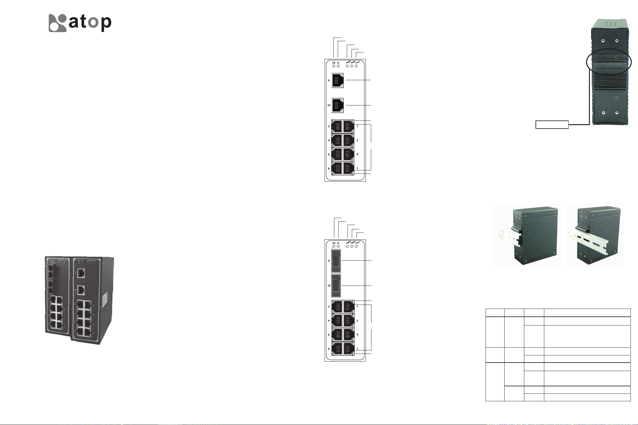
Product Description
1
2
3
4
5
EH7310-G
10-Port Unmanaged Ethernet Switch with
Gigabit Uplinks
6
1. Green: Port 10 LED, Gigabit port
2. Green: Port 9 LED, Gigabit port
3. Green: Power input, PWR1 LED
7
4. Green: Power input, PWR2 LED
5. Red: Fault LED
6. Port 9: 10/100/1000 BaseT(X) port
8
7. Port 10: 10/100/1000 BaseT(X) port
8. Green LED: Switch is actively sending
or receiving
9
9. Port 1~8: 8 ports of 10/100BaseT(X)
with RJ-45 connector
10. Amber LED: Network speed is in full
duplex transfer mode
10
1
2
3
4
5
EH7310-G-2Fm / EH7310-G-2Fs /
EH7310-2Fm / EH7310-2Fs
10-Port Unmanaged Fast Ethernet Switch
6
with 100Mbps/Gigabit Single/Multi-mode
Optical Fiber Uplinks
1. Green: Port 10 LED
7
2. Green: Port 9 LED
3. Green: Power input PWR1 LED
4. Green: Power input PWR2 LED
8
5. Red: Fault LED
6. Port 9: 1000BaseFX port
(EH7310-G-2Fm / EH7310-G-2Fs)
9
100BaseFX port
(EH7310-2Fm / EH7310-2Fs)
7. Port 10: 1000BaseFX port
(EH7310-G-2Fm / EH7310-G-2Fs)
10
100BaseFX port
(EH7310-2Fm / EH7310-2Fs)
8. Green: Switch is actively sending or
receiving
9. Port 1~8: 8 ports of 10/100BaseT(X)
with RJ-45 connector
10. Amber: Network speed is in full
duplex transfer mode
Hardware Installation
■
Electrical
Step 1: Unpack the Switch, check to make
sure no external damages.
Step 2: Connect PWR3 power jack with the
enclosed power supply. It is normal
to see the FAULT indicator on
because it is trigger by the absence
of PWR1 and PWR2.
Step 3: Hook up one RJ-45 port to your LAN,
and another port to your computer.
Check to make sure your host
computer can access the LAN.
Metal Spring
■
Mechanical
All Ethernet Switches are equipped with a DIN-Rail bracket attached
onto the rear panel. Follow the steps below to fasten the switch to the
DIN-Rail.
Step 1: Tilt the unit slightly backwards.
Step 2: Fit the unit over top the DIN-Rail.
Step 3: Push downwards and against the DIN-Rail for locking.
Step 4: Check that the unit is locked into position.
LED Indicators
There are five LED indicators located at the front panel of
EH series.
Name
Fault
PW1/PW2
RJ-45
LED
RED
Green
Green
Amber
Status
Off
On
Off
On
Off
Blink
Off
On
Description
Everything is OK
Something is wrong. It will be lighted
if any power input fails, or any network
port is broken
Power input 1/2 is not plugged yet
Power status is ready
Link is broken, or no cable is plugged in
The device is transferring data through
the port
The link is operated at rate of 10 Mbps
The link is operated at rate of 100 Mbps
Page 2
Configuration and Setting Methods
Any settings or configuration is unnecessary.
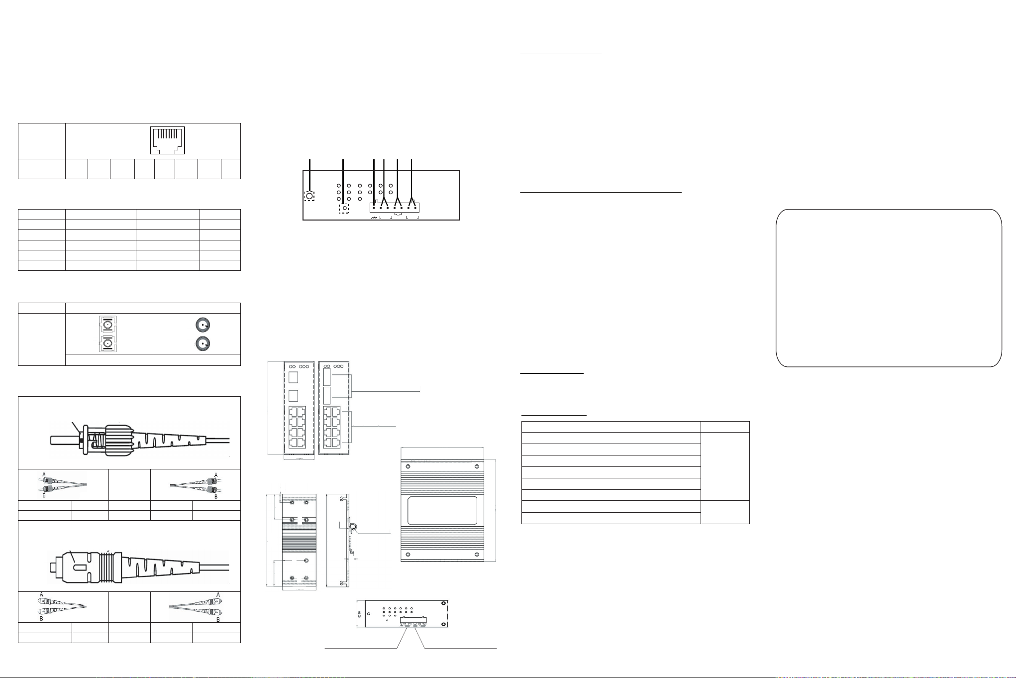
Pin Assignment of Network
Connections
10/100Base-T(X) Ethernet Port Connection
RJ-45
Pin
Signal
Cable type, Max. Transmission and Connector
Cable Type Max. Length Connector
10Base-T
100Base-TX
1000Base-TX
1000Base-SX
1000Base-LX
100Base-Fx Fiber SC/ST Port Connection
Fiber Port
100Base-Fx Fiber SC/ST Cable Wiring
ST Connector
TX
RX
SC Connector
1 2 3 4 5 6 7 8
Tx + T x- R x + Rx-
Cat. 3, 4, 5
Cat. 5 UTP
Cat. 5/Cat. 5e UTP
850µm, multi-mode
1310µm, single-mode
SC Connectors ST Connectors
Tx
Rx
Single-mode Multi-mode
A
B
←→
←→
1 8
UTP 100 m (328 ft)
UTP 100 m (328 ft)
UTP 100 m (328ft)
550m
5 km
Tx
Rx
B
A
RJ-45
RJ-45
RJ-45
SC
SC
RX
TX
7-pin Terminal Block for Power Input
1. Grounding screw
2. Hardware Reset Button
3. Frame Ground
4. Terminal block for power input
PWR1
5. Relay output warning for power failure and break alarm.
Normally Closed.(1A@24VDC)
6. Terminal block for power input PWR2
1 2 3 4 5 6
G V1- V1+ V2- V2+
Relay
PWR1
PWR2
EH7310 series mechanical
dimensions(unit=mm)
There are four LED indicators located at the front panel of
EH series.
Front View
EH7310
141,25
12,50
Real View Panel Mountinrg View
38,60
138,20
38,60
46,20
17,95
32,60
19,30
Front View
EH7310-G-2Fm
EH7310-G-2Fs
EH7310-2Fm
EH7310-2Fs
2-port 10/100/1000Base T(X) (copper)
or 2-port 100Base FX (SC connector)
or 2-port 1000Base FX (SC connector)
8-port 10/100Base T(X)
(RJ-45) shielding with LED
4,00
138,20
6,00
Side View
117,85
DIN-Rail Mount
Warranty Policy
Warranty Conditions
Products supplied by Atop Technologies are covered in this
warranty for sub-standard performance or defective workmanship.
The warranty is not, however, extended to goods damaged in the
following circumstances:
(a) Excessive forces or impacts
(b) War or an Act of God: wind storm, fire, flood, electric shock,
earthquake
(c) Use of unqualified power supply, connectors, or maintenance
procedure
(d) Replacement with unauthorized parts
RMA and Shipping Costs Reimbursement
Customers shall always obtain an authorized "RMA" number from
Atop before shipping the goods to be repaired to Atop. When in
normal use, a sold product shall be replaced with a new one
within 3 months after purchase. The shipping cost from the
customer to Atop will be reimbursed by Atop.
After 3 months and still within the warranty period, it is up to
Atop whether to replace the unit with a new one; normally, as
long as a product is under warranty, all parts and labor are free
of charge to the customers.
After the warranty period, the customer shall cover the cost for
parts and labor.Three months after purchase, the shipping cost
from the customer to Atop will not be reimbursed, but the
shipping cost from Atop to the customer will be paid by Atop.
Limited Liability
Atop shall not be held responsible for any consequential losses
from using Atop’s product.
Warranty Period
Product Categories
Serial-to-Ethernet Server
Serial-to WLAN Server
Industrial Wireless Ethernet Device
Modbus Gateway Series
Industrial Ethernet Switch
Embedded Serial Server
145,70
Pick-to-Light System
Auto-Identification and Data Collection-AIDC
※ Warranty coverage for accessories such as power
adapters and high-gain antenna is one year.
Warranty
5 Years
1 Year
The warranty certification will not be effective until an authorized
stamp issued by Atop’s overseas agents.
Purchase Date: / / (yyyy/mm/dd)
Serial Number:
ATOP Customer Services and Supports
1. Please contact your local dealers or Atop Technical Support
Center at the following numbers.
+ 886-3-550-8137 (Atop Taiwan)
+ 86-21-6495-6232 (Atop China)
2. Please report the defected problems via Atop’s Web site or
E-mail account
Web Site:www.atop.com.tw, e-mail:service@atop.com.tw
Web Site:www.atop.com.cn, e-mail:service@atop.com.cn
TX
RX
45,90
A
B
←→
←→
B
A
RX
TX
Redundant inputs Power Supply
(12/24/48 VDC)
Botton View
PWR1 or PWR2
Failure to Tigger Fault
(Normally Closed) (1A@24 VDC)
─ Any change by website in material announcement primarily. ─
 Loading...